WO2018174130A1 - 油圧緩衝器用外筒、及びこの油圧緩衝器用外筒の成形方法 - Google Patents
油圧緩衝器用外筒、及びこの油圧緩衝器用外筒の成形方法 Download PDFInfo
- Publication number
- WO2018174130A1 WO2018174130A1 PCT/JP2018/011297 JP2018011297W WO2018174130A1 WO 2018174130 A1 WO2018174130 A1 WO 2018174130A1 JP 2018011297 W JP2018011297 W JP 2018011297W WO 2018174130 A1 WO2018174130 A1 WO 2018174130A1
- Authority
- WO
- WIPO (PCT)
- Prior art keywords
- shock absorber
- hydraulic shock
- thermoplastic resin
- outer cylinder
- intermediate body
- Prior art date
- Legal status (The legal status is an assumption and is not a legal conclusion. Google has not performed a legal analysis and makes no representation as to the accuracy of the status listed.)
- Ceased
Links
Images



Classifications
-
- B—PERFORMING OPERATIONS; TRANSPORTING
- B29—WORKING OF PLASTICS; WORKING OF SUBSTANCES IN A PLASTIC STATE IN GENERAL
- B29C—SHAPING OR JOINING OF PLASTICS; SHAPING OF MATERIAL IN A PLASTIC STATE, NOT OTHERWISE PROVIDED FOR; AFTER-TREATMENT OF THE SHAPED PRODUCTS, e.g. REPAIRING
- B29C45/00—Injection moulding, i.e. forcing the required volume of moulding material through a nozzle into a closed mould; Apparatus therefor
- B29C45/14—Injection moulding, i.e. forcing the required volume of moulding material through a nozzle into a closed mould; Apparatus therefor incorporating preformed parts or layers, e.g. injection moulding around inserts or for coating articles
- B29C45/14336—Coating a portion of the article, e.g. the edge of the article
- B29C45/14377—Coating a portion of the article, e.g. the edge of the article using an additional insert, e.g. a fastening element
-
- B—PERFORMING OPERATIONS; TRANSPORTING
- B29—WORKING OF PLASTICS; WORKING OF SUBSTANCES IN A PLASTIC STATE IN GENERAL
- B29C—SHAPING OR JOINING OF PLASTICS; SHAPING OF MATERIAL IN A PLASTIC STATE, NOT OTHERWISE PROVIDED FOR; AFTER-TREATMENT OF THE SHAPED PRODUCTS, e.g. REPAIRING
- B29C45/00—Injection moulding, i.e. forcing the required volume of moulding material through a nozzle into a closed mould; Apparatus therefor
- B29C45/14—Injection moulding, i.e. forcing the required volume of moulding material through a nozzle into a closed mould; Apparatus therefor incorporating preformed parts or layers, e.g. injection moulding around inserts or for coating articles
- B29C45/14778—Injection moulding, i.e. forcing the required volume of moulding material through a nozzle into a closed mould; Apparatus therefor incorporating preformed parts or layers, e.g. injection moulding around inserts or for coating articles the article consisting of a material with particular properties, e.g. porous, brittle
- B29C45/14786—Fibrous material or fibre containing material, e.g. fibre mats or fibre reinforced material
-
- B—PERFORMING OPERATIONS; TRANSPORTING
- B29—WORKING OF PLASTICS; WORKING OF SUBSTANCES IN A PLASTIC STATE IN GENERAL
- B29C—SHAPING OR JOINING OF PLASTICS; SHAPING OF MATERIAL IN A PLASTIC STATE, NOT OTHERWISE PROVIDED FOR; AFTER-TREATMENT OF THE SHAPED PRODUCTS, e.g. REPAIRING
- B29C45/00—Injection moulding, i.e. forcing the required volume of moulding material through a nozzle into a closed mould; Apparatus therefor
- B29C45/14—Injection moulding, i.e. forcing the required volume of moulding material through a nozzle into a closed mould; Apparatus therefor incorporating preformed parts or layers, e.g. injection moulding around inserts or for coating articles
- B29C45/14311—Injection moulding, i.e. forcing the required volume of moulding material through a nozzle into a closed mould; Apparatus therefor incorporating preformed parts or layers, e.g. injection moulding around inserts or for coating articles using means for bonding the coating to the articles
-
- B—PERFORMING OPERATIONS; TRANSPORTING
- B29—WORKING OF PLASTICS; WORKING OF SUBSTANCES IN A PLASTIC STATE IN GENERAL
- B29C—SHAPING OR JOINING OF PLASTICS; SHAPING OF MATERIAL IN A PLASTIC STATE, NOT OTHERWISE PROVIDED FOR; AFTER-TREATMENT OF THE SHAPED PRODUCTS, e.g. REPAIRING
- B29C45/00—Injection moulding, i.e. forcing the required volume of moulding material through a nozzle into a closed mould; Apparatus therefor
- B29C45/14—Injection moulding, i.e. forcing the required volume of moulding material through a nozzle into a closed mould; Apparatus therefor incorporating preformed parts or layers, e.g. injection moulding around inserts or for coating articles
- B29C45/14598—Coating tubular articles
-
- B—PERFORMING OPERATIONS; TRANSPORTING
- B29—WORKING OF PLASTICS; WORKING OF SUBSTANCES IN A PLASTIC STATE IN GENERAL
- B29C—SHAPING OR JOINING OF PLASTICS; SHAPING OF MATERIAL IN A PLASTIC STATE, NOT OTHERWISE PROVIDED FOR; AFTER-TREATMENT OF THE SHAPED PRODUCTS, e.g. REPAIRING
- B29C45/00—Injection moulding, i.e. forcing the required volume of moulding material through a nozzle into a closed mould; Apparatus therefor
- B29C45/14—Injection moulding, i.e. forcing the required volume of moulding material through a nozzle into a closed mould; Apparatus therefor incorporating preformed parts or layers, e.g. injection moulding around inserts or for coating articles
- B29C45/14819—Injection moulding, i.e. forcing the required volume of moulding material through a nozzle into a closed mould; Apparatus therefor incorporating preformed parts or layers, e.g. injection moulding around inserts or for coating articles the inserts being completely encapsulated
-
- B—PERFORMING OPERATIONS; TRANSPORTING
- B29—WORKING OF PLASTICS; WORKING OF SUBSTANCES IN A PLASTIC STATE IN GENERAL
- B29C—SHAPING OR JOINING OF PLASTICS; SHAPING OF MATERIAL IN A PLASTIC STATE, NOT OTHERWISE PROVIDED FOR; AFTER-TREATMENT OF THE SHAPED PRODUCTS, e.g. REPAIRING
- B29C45/00—Injection moulding, i.e. forcing the required volume of moulding material through a nozzle into a closed mould; Apparatus therefor
- B29C45/16—Making multilayered or multicoloured articles
- B29C45/1671—Making multilayered or multicoloured articles with an insert
-
- B—PERFORMING OPERATIONS; TRANSPORTING
- B29—WORKING OF PLASTICS; WORKING OF SUBSTANCES IN A PLASTIC STATE IN GENERAL
- B29C—SHAPING OR JOINING OF PLASTICS; SHAPING OF MATERIAL IN A PLASTIC STATE, NOT OTHERWISE PROVIDED FOR; AFTER-TREATMENT OF THE SHAPED PRODUCTS, e.g. REPAIRING
- B29C45/00—Injection moulding, i.e. forcing the required volume of moulding material through a nozzle into a closed mould; Apparatus therefor
- B29C45/14—Injection moulding, i.e. forcing the required volume of moulding material through a nozzle into a closed mould; Apparatus therefor incorporating preformed parts or layers, e.g. injection moulding around inserts or for coating articles
- B29C45/14311—Injection moulding, i.e. forcing the required volume of moulding material through a nozzle into a closed mould; Apparatus therefor incorporating preformed parts or layers, e.g. injection moulding around inserts or for coating articles using means for bonding the coating to the articles
- B29C2045/14319—Injection moulding, i.e. forcing the required volume of moulding material through a nozzle into a closed mould; Apparatus therefor incorporating preformed parts or layers, e.g. injection moulding around inserts or for coating articles using means for bonding the coating to the articles bonding by a fusion bond
-
- B—PERFORMING OPERATIONS; TRANSPORTING
- B29—WORKING OF PLASTICS; WORKING OF SUBSTANCES IN A PLASTIC STATE IN GENERAL
- B29C—SHAPING OR JOINING OF PLASTICS; SHAPING OF MATERIAL IN A PLASTIC STATE, NOT OTHERWISE PROVIDED FOR; AFTER-TREATMENT OF THE SHAPED PRODUCTS, e.g. REPAIRING
- B29C45/00—Injection moulding, i.e. forcing the required volume of moulding material through a nozzle into a closed mould; Apparatus therefor
- B29C45/14—Injection moulding, i.e. forcing the required volume of moulding material through a nozzle into a closed mould; Apparatus therefor incorporating preformed parts or layers, e.g. injection moulding around inserts or for coating articles
- B29C2045/1486—Details, accessories and auxiliary operations
- B29C2045/14868—Pretreatment of the insert, e.g. etching, cleaning
-
- B—PERFORMING OPERATIONS; TRANSPORTING
- B29—WORKING OF PLASTICS; WORKING OF SUBSTANCES IN A PLASTIC STATE IN GENERAL
- B29K—INDEXING SCHEME ASSOCIATED WITH SUBCLASSES B29B, B29C OR B29D, RELATING TO MOULDING MATERIALS OR TO MATERIALS FOR MOULDS, REINFORCEMENTS, FILLERS OR PREFORMED PARTS, e.g. INSERTS
- B29K2077/00—Use of PA, i.e. polyamides, e.g. polyesteramides or derivatives thereof, as moulding material
-
- B—PERFORMING OPERATIONS; TRANSPORTING
- B29—WORKING OF PLASTICS; WORKING OF SUBSTANCES IN A PLASTIC STATE IN GENERAL
- B29K—INDEXING SCHEME ASSOCIATED WITH SUBCLASSES B29B, B29C OR B29D, RELATING TO MOULDING MATERIALS OR TO MATERIALS FOR MOULDS, REINFORCEMENTS, FILLERS OR PREFORMED PARTS, e.g. INSERTS
- B29K2101/00—Use of unspecified macromolecular compounds as moulding material
- B29K2101/12—Thermoplastic materials
-
- B—PERFORMING OPERATIONS; TRANSPORTING
- B29—WORKING OF PLASTICS; WORKING OF SUBSTANCES IN A PLASTIC STATE IN GENERAL
- B29K—INDEXING SCHEME ASSOCIATED WITH SUBCLASSES B29B, B29C OR B29D, RELATING TO MOULDING MATERIALS OR TO MATERIALS FOR MOULDS, REINFORCEMENTS, FILLERS OR PREFORMED PARTS, e.g. INSERTS
- B29K2105/00—Condition, form or state of moulded material or of the material to be shaped
- B29K2105/06—Condition, form or state of moulded material or of the material to be shaped containing reinforcements, fillers or inserts
- B29K2105/12—Condition, form or state of moulded material or of the material to be shaped containing reinforcements, fillers or inserts of short lengths, e.g. chopped filaments, staple fibres or bristles
-
- B—PERFORMING OPERATIONS; TRANSPORTING
- B32—LAYERED PRODUCTS
- B32B—LAYERED PRODUCTS, i.e. PRODUCTS BUILT-UP OF STRATA OF FLAT OR NON-FLAT, e.g. CELLULAR OR HONEYCOMB, FORM
- B32B2260/00—Layered product comprising an impregnated, embedded, or bonded layer wherein the layer comprises an impregnation, embedding, or binder material
- B32B2260/04—Impregnation, embedding, or binder material
- B32B2260/046—Synthetic resin
-
- B—PERFORMING OPERATIONS; TRANSPORTING
- B32—LAYERED PRODUCTS
- B32B—LAYERED PRODUCTS, i.e. PRODUCTS BUILT-UP OF STRATA OF FLAT OR NON-FLAT, e.g. CELLULAR OR HONEYCOMB, FORM
- B32B2262/00—Composition or structural features of fibres which form a fibrous or filamentary layer or are present as additives
- B32B2262/10—Inorganic fibres
- B32B2262/106—Carbon fibres, e.g. graphite fibres
Definitions
- the present invention relates to a hydraulic shock absorber outer cylinder and a method of forming the hydraulic shock absorber outer cylinder.
- Patent Document 1 discloses a motor having a rotating shaft formed of a carbon fiber reinforced plastic.
- the rotation axis of the motor is inclined at a predetermined angle with respect to the direction in which the rotation axis extends in the direction in which the carbon fibers of the carbon fiber fabric forming the rotation axis extend.
- this motor can make the torsion breaking torque of the rotating shaft formed with the carbon fiber reinforced plastic have a desired strength.
- this motor can be made into a carbon fiber reinforced plastic instead of a metal rotating shaft, the weight can be reduced compared with the case where a metal rotating shaft is used.
- the rotating shaft of this motor is formed by heating and compressing (pressing) a carbon fiber fabric dipped in a mold resin. That is, the rotating shaft of this motor is formed using a thermosetting resin.
- a thermosetting resin for solidifying a carbon fiber fabric using a thermosetting resin, it is necessary to heat and compress (press) it for a long time in a vacuum. For this reason, productivity of the rotating shaft of this motor is not good.
- corrugation on the outside it is difficult to heat-compress (press) according to a complicated unevenness
- the present invention has been completed based on the above circumstances, and an object thereof is to provide a hydraulic shock absorber outer cylinder with good productivity and a method of forming the hydraulic shock absorber outer cylinder.
- the outer cylinder for a hydraulic shock absorber includes a cylindrical body and a molded body.
- the cylindrical body is obtained by texturing a continuous reinforcing fiber into a cylindrical shape.
- the molded body is molded of a thermoplastic resin that forms irregularities on the outside of the cylindrical body while impregnating the cylindrical body.
- textile processing is processing which manufactures a flat or cylindrical cloth, a string, etc. by assembling a fiber, weaving, or knitting.
- the tubular body of the present invention can be textile processed from continuous reinforcing fibers.
- the method for molding an outer cylinder for a hydraulic shock absorber may include an intermediate forming step and an injection molding step.
- the intermediate forming step a mixed yarn in which continuous reinforcing fibers and a thermoplastic resin component are mixed is knitted into a cylinder along the outer peripheral surface of a mandrel to form a cylindrical intermediate.
- the injection molding step a thermoplastic resin is injected into a mold having an intermediate body disposed therein, and a molded body that forms irregularities on the outside of the intermediate body is formed while being integrated with the intermediate body.
- the intermediate thermoplastic resin component can be heated and melted by the heat of the thermoplastic resin injected into the mold.
- the method for molding an outer cylinder for a hydraulic shock absorber according to the present invention may include a solidification step between the intermediate formation step and the injection molding step.
- the intermediate is heated to melt and cool the thermoplastic resin component to obtain a solidified intermediate.
- the method for forming an outer cylinder for a hydraulic shock absorber according to the present invention may include a coating step between the intermediate formation step and the solidification step.
- a covering material having a thermal conductivity higher than that of the intermediate body is adhered to the outer peripheral surface of the intermediate body to cover the intermediate body.
- an outer case 10 that is an outer cylinder for a hydraulic shock absorber includes an outer case main body 10A, a spring receiving portion 10B, and a knuckle bracket 10C.
- the outer case 10 is used as an outer case 10 of a strut type suspension that is a shock absorber 50 interposed between a vehicle (not shown) and a vehicle wheel (not shown). Yes (see FIG. 2).
- the outer case body 10A which is a molded body, has a cylindrical shape and extends in one direction.
- the outer case main body 10A is formed by injection molding a thermoplastic resin such as polyamide.
- the outer case body 10A has one end opened and the other end closed. Further, the outer case body 10A is provided with a metal first metal fitting 10D at one open end.
- the first metal fitting 10D is connected to the outer case body 10A by insert molding, outsert molding, or other joining and fastening methods.
- the first metal fitting 10D has a cylindrical shape, and one end and the other end are opened and communicated with each other.
- the first metal fitting 10D has an outer diameter at the other end smaller than an outer diameter at the one end.
- the first metal fitting 10D is provided so that the outer periphery of the other end is in contact with the inner periphery of one end of the outer case main body 10A and communicates with one end of the outer case main body 10A.
- the outer case main body 10A is provided with an intermediate body 20 which is a cylindrical body.
- the intermediate 20 is knitted (textile processed) into a cylindrical fiber having one end and the other end communicating with each other, and a mixed fiber 20A containing carbon fibers that are continuous reinforcing fibers and a thermoplastic resin component. It is formed. That is, the intermediate body 20 which is a cylindrical body is obtained by weaving carbon fibers into a cylindrical shape.
- the thermoplastic resin component is obtained by molding a thermoplastic resin such as polyamide into a fiber shape.
- the thermoplastic resin component is the same material as the thermoplastic resin forming the outer case body 10A.
- the intermediate body 20 has an inner diameter slightly larger than the inner diameter of the cylindrical outer case body 10A.
- the intermediate body 20 has an outer diameter slightly smaller than the outer diameter of the cylindrical outer case body 10A. Further, the intermediate body 20 has a dimension in the longitudinal direction slightly smaller than the dimension in the longitudinal direction of the cylindrical outer case main body 10A.
- the intermediate body 20 is provided in the outer case main body 10A by insert molding.
- the intermediate body 20 is covered with a thermoplastic resin forming the outer case main body 10A. Thereby, this outer case 10 can make mechanical properties, such as rigidity, favorable compared with the case where the intermediate body 20 is not provided.
- the spring receiving portion 10B is provided so as to protrude outwardly from the outer peripheral surface of the intermediate portion in the longitudinal direction of the outer case main body 10A.
- the spring receiving portion 10B is formed by injection molding using a thermoplastic resin such as polyamide, and is formed integrally with the outer case main body 10A.
- a pair of knuckle brackets 10C is provided at the other end of the outer case body 10A.
- the knuckle bracket 10C is formed by injection molding using a thermoplastic resin such as polyamide, and is integrally formed with the outer case main body 10A.
- These knuckle brackets 10 ⁇ / b> C have planar portions 10 ⁇ / b> F that are formed in a planar shape and face each other.
- the direction in which the flat planar portion 10F extends is parallel to the longitudinal direction of the outer case main body 10A.
- the outer case main body 10A is formed of a thermoplastic resin that forms the spring receiving portion 10B and the knuckle bracket 10C on the outer side of the intermediate body 20. Note that the spring receiving portion 10B and the knuckle bracket 10C are examples of irregularities.
- each of these knuckle brackets 10C is provided with two second metal fittings 10E.
- These second metal fittings 10E are provided on the knuckle bracket 10C by insert molding.
- the second metal fitting 10E has a cylindrical shape, and one end and the other end are opened and communicated with each other.
- These second metal fittings 10E are provided on each of the pair of knuckle brackets 10C with the direction in which the cylindrical central axis extends in the direction perpendicular to the flat planar portion 10F of the knuckle bracket 10C.
- the cylindrical central axes of the two second metal fittings 10E provided on the respective knuckle brackets 10C are arranged on a straight line.
- the second metal fitting 10E is not filled with a thermoplastic resin inside the cylindrical shape, and one end and the other end are opened and communicated with each other.
- the outer case 10 is formed.
- FIG. 2 shows an example of a shock absorber 50 using the outer case 10.
- the shock absorber 50 includes an outer case 10, a piston rod 11, and a suspension spring 12.
- the piston rod 11 has a cylindrical shape, and is inserted into the outer case main body 10A from the open end of the outer case main body 10A so as to be extendable and contractable with respect to the outer case main body 10A.
- the piston rod 11 is provided with an upper mount (not shown) at the tip protruding from the open end of the outer case body 10A.
- the upper mount is provided with a spring receiving surface (not shown) facing the spring receiving portion 10B having the shape of an outer case.
- the suspension spring 12 is a compression coil spring.
- the suspension spring 12 is provided by being inserted into the piston rod 11 and the outer case main body 10A.
- the suspension spring 12 is provided between the spring receiving portion 10B of the outer case 10 and the spring receiving surface of the upper mount.
- the shock absorber 50 using the outer case 10 is configured.
- the shock absorber 50 has an upper mount connected to the vehicle side, and a knuckle (not shown) provided on a vehicle wheel is disposed between the opposed flat surface portions 10F of the pair of knuckle brackets 10C of the outer case 10. And it can connect and it can interpose between a vehicle and the wheel of a vehicle.
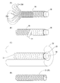
- a blended yarn 20A in which continuous reinforcing fibers and a thermoplastic resin component are blended is knitted into a cylindrical shape along the outer peripheral surface of the mandrel 30 to form a cylindrical intermediate body. 20 (intermediate production process).
- the mixed fiber 20A is incorporated into a braiding device (not shown).
- the braiding device is a known device, and a plurality of bobbins (FIG. 1) are wound around and held around a mandrel 30 that is long in one direction and has a circular outer shape, and a mixed yarn 20A that is a braid. Not shown).
- Each of these spools is arranged side by side in the circumferential direction of the outer surface of the mandrel 30 so as to surround the outer surface of the mandrel 30 with a predetermined distance from the outer surface of the mandrel 30 (not shown).
- This braiding apparatus can manufacture the intermediate body 20 which is a cylindrical braid by weaving the mixed yarn 20A along the outer peripheral surface of the mandrel 30 using the mixed yarn 20A wound around each of the plurality of spools. (See FIG. 3A.) That is, the intermediate body 20 which is a cylindrical body is one in which carbon fibers are knitted into a cylindrical braid.
- a covering material 31 having a thermal conductivity higher than that of the intermediate body 20 is brought into close contact with the outer peripheral surface of the intermediate body 20 to cover the intermediate body 20 (covering step).
- a covering material 31 is wound around the outer peripheral surface of the intermediate body 20 knitted along the outer peripheral surface of the mandrel 30.
- the covering material 31 has a predetermined width and has a strip shape extending in one direction.
- the covering material 31 is made of a metal such as stainless steel. At this time, the covering material 31 is spirally wound around the outer peripheral surface of the intermediate body 20.
- covers the outer peripheral surface of the intermediate body 20 so that a clearance gap may not generate
- the coating process is completed.
- the outer peripheral surface of the intermediate body 20 knitted along the outer peripheral surface of the mandrel is covered with a pair of covering materials having a shape obtained by dividing the cylinder in the axial direction. May be compressed.
- the intermediate body 20 covered with the covering material 31 is heated to melt and cool the thermoplastic resin component to obtain the solidified intermediate body 21 (solidification step).
- the intermediate body 20 which is knitted in a cylindrical shape on the outer peripheral surface of the mandrel 30 and the covering material 31 is wound around the outer peripheral surface, is put into a heater 32.
- the heater 32 is long in one direction, and the cross-sectional shape in the direction perpendicular to the longitudinal direction is an arc.
- the heater 32 has an arc-shaped inner diameter larger than the outer diameter of the covering material 31 wound around the outer peripheral surface of the intermediate body 20.
- the intermediate body 20 which is knitted in a cylindrical shape on the outer peripheral surface of the mandrel 30 in the heater 32 and has the covering material 31 wound around the outer peripheral surface, is introduced along the longitudinal direction of the heater 32. Then, the thermoplastic resin component of the intermediate 20 put in the heater 32 is melted, and the melted thermoplastic resin component is impregnated into the carbon fiber of the intermediate 20 without protruding from the coating material 31 to the outside. Then, after a predetermined time, the intermediate body 20 knitted in a cylindrical shape on the outer peripheral surface of the mandrel 30 and the covering material 31 is wound around the outer peripheral surface is taken out from the heater 32 and cooled. Thereby, the thermoplastic resin component melted and impregnated in the carbon fibers of the intermediate 20 is solidified again. Thus, the solidification process is completed.
- the covering material 31 wound around the outer peripheral surface of the intermediate body 20 is wound off from the outer peripheral surface of the intermediate body 20 and removed, and the mandrel 30 is extracted from the intermediate body 20.
- the solidified intermediate 21 which is the intermediate 20 solidified while maintaining the cylindrical shape can be obtained.
- the covering material 31 and the mandrel 30 removed from the solidified intermediate 21 can be used repeatedly.
- the solidified intermediate 21, the first metal fitting 10D, and the second metal fitting 10E obtained in this way are arranged in the molding space 41 in the mold 40.
- the mold 40 is opened, and the first metal fitting 10D and the solidified intermediate 21 are inserted into a cylindrical core pin 40A provided in the molding space 41 in the mold 40. And place it.
- one end of the solidified intermediate 21 and the other end of the first metal fitting 10D are in contact with each other.
- the inner diameter of the first metal fitting 10D and the outer diameter of the core pin 40A are substantially the same. That is, the inner peripheral surface of the first metal fitting 10D is in contact with the outer peripheral surface of the core pin 40A.
- the solidified intermediate 21 has a slightly larger inner diameter than the outer diameter of the core pin 40A. Thereby, the solidification intermediate body 21 can be arrange
- thermoplastic resin is injected into the molding space 41 in the mold 40 in which the solidified intermediate 21, the first metal fitting 10 ⁇ / b> D, and the second metal fitting 10 ⁇ / b> E are arranged, and the solidified intermediate is integrated with the solidified intermediate 21.
- An outer case main body 10A that forms irregularities on the outside of the body 21 is formed (injection molding step).
- the thermoplastic resin is injected into the molding space 41 in the mold 40 in which the solidified intermediate body 21, the first metal fitting 10D, and the second metal fitting 10E are arranged.
- the thermoplastic resin injected into the molding space 41 in the mold 40 covers the entire outer peripheral surface and inner peripheral surface of the solidified intermediate 21.
- thermoplastic resin component of the solidified intermediate 21 is melted again by the heat of the thermoplastic resin injected into the molding space 41 in the mold 40. That is, the thermoplastic resin component of the solidified intermediate 21 is heated and melted by the heat of the thermoplastic resin injected into the molding space 41 in the mold 40. Then, the thermoplastic resin component in the vicinity of the outer peripheral surface and inner peripheral surface of the solidified intermediate 21 is fused with the thermoplastic resin injected into the molding space 41 in the mold 40. In addition, when there is a region in which the thermoplastic resin component is not impregnated in the solidified intermediate 21, the thermoplastic resin injected into the molding space 41 in the mold 40 is impregnated with the thermoplastic resin component of the solidified intermediate 21.
- Impregnate no area After the injected thermoplastic resin is filled to every corner of the molding space 41 in the mold 40, pressure holding and cooling are performed, the mold 40 is opened, and the outer case 10 is molded in the mold 40. Remove from space 41. Thus, the injection molding process is completed.
- the thermoplastic resin components near the outer peripheral surface and the inner peripheral surface of the solidified intermediate body 21 are fused with the thermoplastic resin injected into the molding space 41 in the mold 40. And the thermoplastic resin injected into the molding space 41 in the mold 40 are difficult to peel off.
- the outer cylinder for the hydraulic shock absorber is molded by impregnating continuous reinforcing fibers with a thermoplastic resin that has been heated and dissolved.
- the thermoplastic resin heated and dissolved can be solidified in a short time by cooling.
- the thermoplastic resin does not require heat compression (pressing) and can be injected and molded into the molding space 41 in the mold 40, so that a desired shape can be easily obtained. For this reason, this outer cylinder for hydraulic shock absorbers can be easily provided with complex irregularities by using a thermoplastic resin.
- the outer cylinder for a hydraulic shock absorber according to the present invention has good productivity.
- this tubular body is knitted with braided continuous reinforcing fibers.
- a braid is produced by crossing braids (fiber bundles) with each other. The crossing angle of the braid can be arbitrarily changed. That is, this cylindrical body can change the mechanical characteristics of the cylindrical body itself by changing the assembly structure in various ways.
- the molding method of the outer cylinder for the hydraulic shock absorber includes an intermediate forming process and an injection molding process.
- a mixed fiber 20A in which continuous reinforcing fibers and a thermoplastic resin component are mixed is knitted in a cylindrical shape along the outer peripheral surface of the mandrel 30 to form a cylindrical intermediate body 20.
- a thermoplastic resin is injected into the molding space 41 of the mold 40 in which the intermediate body 20 is disposed in the molding space 41, and the outer case body is formed integrally with the intermediate body 20 while forming irregularities on the outer side of the intermediate body 20. 10A is formed.
- the intermediate body 20 formed in advance with a desired outer diameter can be arranged in the molding space 41 in the mold 40.
- the molding method of the outer cylinder for the hydraulic shock absorber can easily adjust the position where the intermediate body 20 is arranged in the molding space 41 in the mold 40.
- the outer cylinder for the hydraulic shock absorber can be molded by impregnating continuous reinforcing fibers with a thermoplastic resin that has been heated and dissolved. The thermoplastic resin heated and dissolved can be solidified in a short time by cooling.
- this method of forming the outer cylinder for a hydraulic shock absorber can easily form the outer cylinder for a hydraulic shock absorber having desired mechanical characteristics, and has good productivity.
- thermoplastic resin component of the intermediate 20 is heated and melted by the heat of the thermoplastic resin injected into the molding space 41 in the mold 40.
- the thermoplastic resin component when the thermoplastic resin component is melted, it is fused with the thermoplastic resin injected into the molding space 41 in the mold 40 while impregnating the continuous reinforcing fiber of the intermediate body. can do.
- the hydraulic shock absorber outer cylinder can form a hydraulic shock absorber outer cylinder with better mechanical characteristics.
- this molding method of the outer cylinder for the hydraulic shock absorber includes a solidification step between the intermediate forming step and the injection molding step.
- the intermediate 20 is heated to melt and cool the thermoplastic resin component to obtain a solidified intermediate 21.
- the molding method of the outer cylinder for hydraulic shock absorbers can melt the thermoplastic resin component of the intermediate in advance, it is possible to satisfactorily impregnate the molten thermoplastic resin component into the continuous reinforcing fibers.
- this method for forming the outer cylinder for a hydraulic shock absorber can form an outer cylinder for a hydraulic shock absorber having better mechanical characteristics.
- this method of forming the outer cylinder for a hydraulic shock absorber includes a coating step between the intermediate formation step and the solidification step.
- the covering step the covering member 31 having a thermal conductivity higher than that of the intermediate body 20 is brought into close contact with the outer peripheral surface of the intermediate body 20 to cover the intermediate body 20.
- a covering process can stick the gap between the continuous reinforcing fiber bundles of the intermediate body 20 by tightly covering the outer peripheral surface of the intermediate body 20 while applying tension to the covering material 31, and internal defects and Therefore, the mechanical properties can be improved.
- the intermediate body 20 with the covering material 31 it is possible to prevent the thermoplastic resin component from being melted out of the intermediate body 20 during heating.
- this coating material 31 has a higher thermal conductivity than the intermediate body 20, heat can be uniformly applied throughout the intermediate body 20 in the solidification step, and the thermoplastic resin component of the intermediate body 20 can be melted without unevenness.
- the molten thermoplastic resin component can be more satisfactorily impregnated between the continuous reinforcing fiber bundles, and an outer cylinder for a hydraulic shock absorber having better mechanical properties can be formed.
- the outer case of the shock absorber is disclosed as a cylindrical body.
- the present invention is not limited thereto, and any type may be used as long as it is a cylindrical member.
- a mixed yarn in which carbon fibers and a thermoplastic resin component are mixed is knitted into a braided shape, but the present invention is not limited to this, and the mixed yarn is entangled in a nonwoven fabric shape to form a cylinder.
- a shaped body may be formed.
- a cylindrical body may be formed by assembling, weaving, or knitting a mixed yarn.
- thermoplastic resin and the thermoplastic resin component are used for the thermoplastic resin and the thermoplastic resin component.
- thermoplastic resins may be used for the thermoplastic resin and the thermoplastic resin component. These resins may be used in combination.
- stainless steel is used for the covering material, but the present invention is not limited to this, and other metals may be used for the covering material.
- carbon fibers are used as the continuous reinforcing fibers, but the present invention is not limited thereto, and other fibers such as glass fibers and aramid fibers may be used as the continuous reinforcing fibers. These fibers may be used in combination.
- the present invention is not limited to this, and the first metal fitting may not be provided, and a space in which the first metal fitting is provided is filled with a thermoplastic resin, continuous reinforcing fiber, or the like. May be formed.
- the spring receiving portion provided in the circumferential direction of the cylindrical body and the knuckle bracket are exemplified as the irregularities, but the irregularities are not limited to the circumferential direction, and the irregularities are formed in the axial direction of the cylindrical body. May be.
- the mounting eye may be formed as irregularities provided in the axial direction of the cylindrical body.
- 10A outer case body (molded body), 20: intermediate body (tubular body), 30 ... mandrel, 31 ... covering material, 21 ... solidified intermediate body (intermediate body)
Landscapes
- Engineering & Computer Science (AREA)
- Manufacturing & Machinery (AREA)
- Mechanical Engineering (AREA)
- Injection Moulding Of Plastics Or The Like (AREA)
- Fluid-Damping Devices (AREA)
- Moulds For Moulding Plastics Or The Like (AREA)
- Moulding By Coating Moulds (AREA)
Abstract
生産性が良好な、油圧緩衝器用外筒、及びこの油圧緩衝器用外筒の成形方法を提供する。 油圧緩衝器用外筒は中間体(20)及びアウターケース本体(10A)を備えている。中間体(20)は連続強化繊維を筒状に編み込んだ(テキスタイル加工した)ものである。アウターケース本体(10A)は中間体(20)に含浸させつつ、中間体(20)の外側に凹凸を形成する熱可塑性樹脂であるポリアミド樹脂で成形されている。テキスタイル加工とは、繊維を組んだり、織ったり、編んだりして、平坦あるいは筒状の布や紐等を製造する加工である。
Description
本発明は油圧緩衝器用外筒、及びこの油圧緩衝器用外筒の成形方法に関するものである。
特許文献1は、炭素繊維強化プラスティック(plastic)で形成した回転軸を有するモータ(motor)が開示されている。このモータの回転軸は、回転軸を形成する炭素繊維繊布の炭素繊維の伸びる方向を回転軸が伸びる方向に対して所定の角度に傾けている。これにより、このモータは炭素繊維強化プラスティックで形成した回転軸のねじれ破断トルクを所望の強度にすることができる。これにより、このモータは金属製の回転軸に替えて炭素繊維強化プラスティックにすることができるため、金属製の回転軸を用いる場合に比べて重量を軽量にすることができる。
このモータの回転軸は、モールド(mold)用樹脂に浸された炭素繊維繊布を加熱圧縮(プレス(press))して成形している。つまり、このモータの回転軸は熱硬化性樹脂を用いて成形されている。熱硬化性樹脂を用いて炭素繊維繊布を固化する場合、真空中で長時間かけて加熱圧縮(プレス)する必要がある。このため、このモータの回転軸は生産性が良好でない。また、熱硬化性樹脂を外側に複雑な凹凸を有する油圧緩衝器用外筒の成形に用いる場合、複雑な凹凸に合わせて加熱圧縮(プレス)することが難しい。このため、熱硬化性樹脂を油圧緩衝器用外筒の成形に用いることは難しい。
本発明は上記のような事情に基づいて完成されたものであって、生産性が良好な、油圧緩衝器用外筒、及びこの油圧緩衝器用外筒の成形方法を提供することを目的とする。
本発明の油圧緩衝器用外筒は筒状体及び成形体を備えている。筒状体は連続強化繊維を筒状にテキスタイル(textile)加工したものである。成形体は筒状体に含浸させつつ、筒状体の外側に凹凸を形成する熱可塑性樹脂で成形されている。
なお、テキスタイル加工とは、繊維を組んだり、織ったり、編んだりして、平坦あるいは筒状の布や紐等を製造する加工である。
本発明の筒状体は連続強化繊維をテキスタイル加工され得る。
本発明の油圧緩衝器用外筒の成形方法は、中間体形成工程、及び射出成形工程を備え得る。中間体形成工程は連続強化繊維と熱可塑性樹脂成分とを混繊した混繊糸をマンドレル(mandrel)の外周面に沿って筒状に編み込み、筒状をなした中間体を形成する。射出成形工程は中間体を内部に配置した金型に熱可塑性樹脂を射出し、中間体と一体化しつつ、中間体の外側に凹凸を形成する成形体を形成する。
本発明の射出成形工程は、金型に射出された熱可塑性樹脂が有する熱によって中間体の熱可塑性樹脂成分が加熱されて融解し得る。
本発明の油圧緩衝器用外筒の成形方法は中間体形成工程と射出成形工程との間に固化工程を備え得る。固化工程は中間体を加熱して熱可塑性樹脂成分を融解して冷却し固化中間体を得る。
本発明の油圧緩衝器用外筒の成形方法は、中間体形成工程と固化工程との間に、被覆工程を備え得る。被覆工程は中間体より熱伝導率の大きい被覆材を中間体の外周面に密着して中間体を覆う。
<実施形態>
油圧緩衝器用外筒であるアウターケース10は、図1に示すように、アウターケース本体10A、ばね受け部10B、ナックルブラケット(knuckle bracket)10Cを備えている。このアウターケース10は車両(図示せず)と車両の車輪(図示せず)との間に介装される緩衝装置50であるストラット(strut)式サスペンション(suspension)のアウターケース10として用いることができる(図2参照。)。
油圧緩衝器用外筒であるアウターケース10は、図1に示すように、アウターケース本体10A、ばね受け部10B、ナックルブラケット(knuckle bracket)10Cを備えている。このアウターケース10は車両(図示せず)と車両の車輪(図示せず)との間に介装される緩衝装置50であるストラット(strut)式サスペンション(suspension)のアウターケース10として用いることができる(図2参照。)。
成形体であるアウターケース本体10Aは円筒状をなして一方向に伸びている。アウターケース本体10Aはポリアミド(polyamide)等の熱可塑性樹脂を射出成形して形成する。アウターケース本体10Aは一端が開口し他端が閉鎖されている。また、アウターケース本体10Aは開口した一端に金属製の第1金具10Dが設けられている。第1金具10Dはインサート(insert)成形、あるいは、アウトサート(outsert)成形、又は、その他の接合締結方法によってアウターケース本体10Aに連結されている。第1金具10Dは円筒状をなしており、一端と他端とが開口して連通している。また、第1金具10Dは他端部の外径が一端部の外径より小さい。第1金具10Dは他端部の外周がアウターケース本体10Aの一端部の内周に当接して、アウターケース本体10Aの一端に連通して設けられている。
また、アウターケース本体10Aは筒状体である中間体20が設けられている。ここで中間体20とは、連続強化繊維である炭素繊維と熱可塑性樹脂成分とを含んだ混繊糸20Aを一端と他端とが連通して開口した円筒状に編み込み(テキスタイル加工して)形成されたものである。つまり、筒状体である中間体20は炭素繊維を筒状に編み込んだものである。熱可塑性樹脂成分はポリアミド等の熱可塑性樹脂を繊維状に成形したものである。熱可塑性樹脂成分はアウターケース本体10Aを形成する熱可塑性樹脂と同様の材質である。中間体20は内径が円筒状のアウターケース本体10Aの内径より僅かに大きい。また、中間体20は外径が円筒状のアウターケース本体10Aの外径より僅かに小さい。また、中間体20は長手方向の寸法が円筒状のアウターケース本体10Aの長手方向の寸法より僅かに小さい。中間体20はインサート成形によってアウターケース本体10A内に設けられている。中間体20はアウターケース本体10Aを形成する熱可塑性樹脂によって周りを覆われている。これにより、このアウターケース10は、中間体20を設けない場合に比べて剛性等の力学的性質を良好にすることができる。
ばね受け部10Bはアウターケース本体10Aの長手方向の中間部の外周面から外方向に鍔状に突出して設けられている。ばね受け部10Bはポリアミド等の熱可塑性樹脂を用いて射出成形で形成されており、アウターケース本体10Aと一体的に形成されている。
ナックルブラケット10Cはアウターケース本体10Aの他端部に一対が設けられている。ナックルブラケット10Cはポリアミド等の熱可塑性樹脂を用いて射出成形で形成されており、アウターケース本体10Aと一体的に形成されている。これらナックルブラケット10Cは互いに平面状に形成され対向した平面部10Fを有している。これらナックルブラケット10Cは平面状の平面部10Fが伸びる方向がアウターケース本体10Aの長手方向に平行である。こうして、アウターケース本体10Aは中間体20の外側にばね受け部10Bやナックルブラケット10Cを形成する熱可塑性樹脂で成形されている。なお、ばね受け部10B、及びナックルブラケット10Cは凹凸を例示するものである。
また、これらナックルブラケット10Cはそれぞれに2つずつ第2金具10Eが設けられている。これら第2金具10Eはインサート成形によってナックルブラケット10Cに設けられている。第2金具10Eは円筒状をなしており一端と他端とが開口して連通している。これら第2金具10Eは円筒状の中心軸が伸びる方向をナックルブラケット10Cの平面状の平面部10Fに対して垂直方向に向けて、一対のナックルブラケット10Cのそれぞれに設けられている。また、一対のナックルブラケット10Cはそれぞれに設けられた2つの第2金具10Eの円筒状の中心軸が互いに一直線上に配置されている。また、これら第2金具10Eは円筒状の内側に熱可塑性樹脂が充填されておらず、一端と他端とが開口して連通している。こうして、このアウターケース10が形成されている。
図2にこのアウターケース10を用いた緩衝装置50の一例を示す。この緩衝装置50はアウターケース10、ピストンロッド(piston rod)11、及び懸架ばね12を有している。ピストンロッド11は円柱状をなして、アウターケース本体10Aに対して伸縮自在にアウターケース本体10Aの開口した一端からアウターケース本体10A内に挿入されている。また、ピストンロッド11はアウターケース本体10Aの開口した一端から突出した先端にアッパーマウント(upper mount)(図示せず)が設けられている。アッパーマウントはアウターケースの鍔状をなしたばね受け部10Bに対向したばね受け面(図示せず)が設けられている。
懸架ばね12は圧縮コイルばねである。懸架ばね12はピストンロッド11、及びアウターケース本体10Aに挿通されて設けられている。懸架ばね12はアウターケース10のばね受け部10Bとアッパーマウントのばね受け面とに挟まれて設けられている。こうしてこのアウターケース10を用いた緩衝装置50が構成されている。
この緩衝装置50はアッパーマウントを車両側に連結し、アウターケース10の一対のナックルブラケット10Cの対向した平面部10Fの間に車両の車輪に設けられたナックル(knuckle)(図示せず)を配置し連結して、車両と車両の車輪との間に介装することができる。
次に、アウターケース10の形成方法を、図3(A)~(D)、及び図4を参照しつつ説明する。
先ず、図3(A)に示すように、連続強化繊維と熱可塑性樹脂成分とを混繊した混繊糸20Aをマンドレル30の外周面に沿って筒状に編み込み、筒状をなした中間体20を形成する(中間体製造工程。)。
先ず、混繊糸20Aをブレイディング(braiding)装置(図示せず)に組み込む。ここで、ブレイディング装置とは公知の装置であり、一方向に長く形成され、外形が円形状をなしたマンドレル30、及び組糸である混繊糸20Aを巻き付けて保持する複数の糸巻き(図示せず)を有している。これら糸巻きはそれぞれがマンドレル30の外周面に対して所定の距離を設けて、マンドレル30の外周面を囲むようにマンドレル30の外周面の周方向に並んで配置されている(図示せず)。このブレイディング装置は複数の糸巻きのそれぞれに巻き付けられた混繊糸20Aを用いてマンドレル30の外周面に沿って混繊糸20Aを編み込み、筒状の組紐である中間体20を製造することができる(図3(A)参照。)。つまり、筒状体である中間体20は炭素繊維を筒状の組紐状に編み込んだものである。
次に、中間体形成工程と後述する固化工程との間に、中間体20より熱伝導率の大きい被覆材31を中間体20の外周面に密着して中間体20を覆う(被覆工程。)。詳しくは、図3(B)に示すように、マンドレル30の外周面に沿って編み込まれた中間体20の外周面に被覆材31を巻き付ける。被覆材31は所定の幅を有し、一方向に長く伸びた帯状をなしている。被覆材31はステンレス(stainless steel)等の金属で形成されている。このとき、被覆材31は中間体20の外周面に螺旋状に巻き付ける。また、被覆材31は螺旋状に隣り合う間に隙間が発生しないように、中間体20の外周面を被覆する。こうして被覆工程を終了する。また、帯状の被覆材31に代えて、円筒を軸方向で半割した形状をなした一対の被覆材でマンドレルの外周面に沿って編み込まれた中間体20の外周面を覆い、中間体20を圧縮しても良い。
次に、被覆材31に覆われた中間体20を加熱して熱可塑性樹脂成分を融解して冷却して固化中間体21を得る(固化工程。)。図3(C)に示すように、マンドレル30の外周面に円筒状に編みこまれ、外周面に被覆材31が巻きつけられた中間体20をヒーター(heater)32に投入する。詳しくは、このヒーター32は一方向に長く形成され、長手方向に対する直角方向の断面形状が円弧状をなしている。このヒーター32は円弧状の内径が中間体20の外周面に巻きつけられた被覆材31の外径より大きい。このヒーター32内にマンドレル30の外周面に円筒状に編みこまれ、外周面に被覆材31が巻きつけられた中間体20をヒーター32の長手方向に沿って投入する。すると、ヒーター32内に投入された中間体20の熱可塑性樹脂成分が融解し、融解した熱可塑性樹脂成分が被覆材31から外側に食み出すことなく中間体20の炭素繊維に含浸する。そして、所定の時間を経た後、マンドレル30の外周面に円筒状に編みこまれ、外周面に被覆材31が巻きつけられた中間体20をヒーター32から取り出して冷却する。これにより、融解して中間体20の炭素繊維に含浸した熱可塑性樹脂成分が再び固化する。こうして固化工程を終了する。
そして、中間体20の外周面に巻きつけられた被覆材31を中間体20の外周面から巻き取って取り外し、マンドレル30を中間体20から抜き取る。こうして、円筒状の形を保ちつつ固化した中間体20である固化中間体21を得ることができる。なお、固化中間体21から取り外した被覆材31、及びマンドレル30は繰り返し使用することができる。
そして、こうして得られた固化中間体21、第1金具10D、及び第2金具10Eを金型40内の成形空間41に配置する。詳しくは、図4に示すように、金型40を開き、金型40内の成形空間41に設けられた円柱状のコアピン(core pin)40Aに第1金具10D、及び固化中間体21を挿通して配置する。このとき、固化中間体21の一端と第1金具10Dの他端とが互いに当接している。また、第1金具10Dの内径とコアピン40Aの外径とはほぼ同一である。つまり、第1金具10Dは内周面がコアピン40Aの外周面に当接している。また、固化中間体21は内径がコアピン40Aの外径より僅かに大きい。これにより、固化中間体21は内周面がコアピン40Aの外周面に接触しないように配置することができる。そして、金型40内の成形空間41に第2金具10Eを配置して、金型40を閉める。このとき、固化中間体21は外周面が金型40内の成形空間41を形成する壁面に接触しないように金型40内の成形空間41に配置されている。
次に、固化中間体21、第1金具10D、及び第2金具10Eを内部に配置した金型40内の成形空間41に熱可塑性樹脂を射出し、固化中間体21と一体化しつつ、固化中間体21の外側に凹凸を形成するアウターケース本体10Aを形成する(射出成形工程。)。詳しくは、固化中間体21、第1金具10D、及び第2金具10Eを内部に配置した金型40内の成形空間41に熱可塑性樹脂を射出する。そして、金型40内の成形空間41に射出された熱可塑性樹脂は、固化中間体21の外周面及び内周面の全体を覆う。
このとき、固化中間体21の熱可塑性樹脂成分が金型40内の成形空間41に射出された熱可塑性樹脂の熱によって再び融解する。つまり、金型40内の成形空間41に射出された熱可塑性樹脂が有する熱によって固化中間体21の熱可塑性樹脂成分が加熱されて融解する。すると、固化中間体21の外周面及び内周面付近の熱可塑性樹脂成分が、金型40内の成形空間41に射出された熱可塑性樹脂と融着する。また、固化中間体21に熱可塑性樹脂成分が含浸していない領域がある場合、金型40内の成形空間41に射出された熱可塑性樹脂は固化中間体21の熱可塑性樹脂成分が含浸していない領域に含浸する。そして、射出した熱可塑性樹脂が金型40内の成形空間41の隅々まで充填された後、保圧、冷却を実行して、金型40を開き、アウターケース10を金型40内の成形空間41から取り出す。こうして射出成形工程を終了する。このアウターケース10は固化中間体21の外周面及び内周面付近の熱可塑性樹脂成分が金型40内の成形空間41に射出された熱可塑性樹脂と融着しているため、固化中間体21と金型40内の成形空間41に射出された熱可塑性樹脂とが剥離し難い。
このように、この油圧緩衝器用外筒は加熱されて溶解した熱可塑性樹脂が連続強化繊維に含浸して成形されている。加熱されて溶解した熱可塑性樹脂は冷却することによって短時間で固化することができる。また、熱可塑性樹脂は加熱圧縮(プレス)が不要であり、金型40内の成形空間41に射出して成形することができるため、所望の形状を容易に得ることができる。このため、この油圧緩衝器用外筒は熱可塑性樹脂を用いることによって、複雑な凹凸を容易に設けることができる。
したがって、本発明の油圧緩衝器用外筒は生産性が良好である。
また、この筒状体は連続強化繊維を組紐状に編み込んでいる。組物は組糸(繊維束)を互いに交差させることにより作製される。組糸の交差角度は任意に変更することができる。つまり、この筒状体は、組物構造を様々に変更することによって、筒状体自体の力学的特性を変更することができる。
また、この油圧緩衝器用外筒の成形方法は、中間体形成工程、及び射出成形工程を備えている。中間体形成工程は連続強化繊維と熱可塑性樹脂成分とを混繊した混繊糸20Aをマンドレル30の外周面に沿って筒状に編み込み、筒状をなした中間体20を形成する。射出成形工程は中間体20を成形空間41に配置した金型40の成形空間41に熱可塑性樹脂を射出し、中間体20と一体化しつつ、中間体20の外側に凹凸を形成するアウターケース本体10Aを形成する。このため、この油圧緩衝器用外筒の成形方法は予め所望の外径に形成した中間体20を金型40内の成形空間41に配置することができる。これにより、この油圧緩衝器用外筒の成形方法は金型40内の成形空間41において、中間体20が配置される位置を容易に調節することができる。また、この油圧緩衝器用外筒の成形方法は加熱されて溶解した熱可塑性樹脂が連続強化繊維に含浸して成形することができる。加熱されて溶解した熱可塑性樹脂は冷却することによって短時間で固化することができる。
したがって、この油圧緩衝器用外筒の成形方法は容易に所望の機械的特性を有した油圧緩衝器用外筒を成形することができ、生産性が良好である。
また、この射出成形工程は、金型40内の成形空間41に射出された熱可塑性樹脂が有する熱によって中間体20の熱可塑性樹脂成分が加熱されて融解する。このため、この油圧緩衝器用外筒の成形方法は熱可塑性樹脂成分が融解すると、中間体の連続強化繊維に含浸しつつ、金型40内の成形空間41に射出された熱可塑性樹脂と融着することができる。これにより、この油圧緩衝器用外筒の成形方法は力学的特性がより良好な油圧緩衝器用外筒を成形することができる。
また、この油圧緩衝器用外筒の成形方法は中間体形成工程と射出成形工程との間に固化工程を備えている。固化工程は中間体20を加熱して熱可塑性樹脂成分を融解して冷却し固化中間体21を得る。このため、この油圧緩衝器用外筒の成形方法は予め中間体の熱可塑性樹脂成分を融解させることができるため、連続強化繊維に融解した熱可塑性樹脂成分を良好に含浸させることができる。このため、この油圧緩衝器用外筒の成形方法は、力学的特性がより良好な油圧緩衝器用外筒を成形することができる。
また、この油圧緩衝器用外筒の成形方法は、中間体形成工程と固化工程との間に、被覆工程を備えている。被覆工程は中間体20より熱伝導率の大きい被覆材31を中間体20の外周面に密着して中間体20を覆う。このため、被覆工程は被覆材31に張力を付与しながら中間体20の外周面に密着させて覆うことによって、中間体20の連続強化繊維束間の隙間を密着させることができ、内部欠陥となる空隙を抑えることができるため、力学的性質をより良好にすることができる。また、被覆材31で中間体20を被覆することで、加熱する際に中間体20から溶け出した熱可塑性樹脂成分の欠落を防ぐことができる。さらに、この被覆材31は中間体20より熱伝導率が大きいため、固化工程において中間体20の全体にわたり熱を均一に加えることができ、中間体20の熱可塑性樹脂成分を斑なく融解でき、融解した熱可塑性樹脂成分が連続強化繊維束間中により良好に含浸させることができ、力学的特性がより良好な油圧緩衝器用外筒を成形することができる。
<他の実施形態>
以下、上記実施形態から変更可能な他の実施形態を簡単に説明する。
(1)実施形態では、筒状体として緩衝装置のアウターケースを開示しているが、これに限らず、筒状をなした部材であれば種類を問わない。
(2)実施形態では、炭素繊維と熱可塑性樹脂成分とを混繊した混繊糸を組紐状に編み込んで形成しているが、これに限らず、混繊糸を不織布状に絡み合わせて筒状体を形成しても良い。また、混繊糸を組んだり、織ったり、編んだりして筒状体を形成しても良い。
(3)実施形態では、熱可塑性樹脂、及び熱可塑性樹脂成分にポリアミド樹脂を用いているが、これに限らず、熱可塑性樹脂、及び熱可塑性樹脂成分に他の熱可塑性樹脂を用いても良く、これら樹脂を複合的に用いても良い。
(4)実施形態では、被覆材にステンレスを用いているが、これに限らず、被覆材に他の金属を用いても良い。
(5)実施形態では、連続強化繊維に炭素繊維を用いているが、これに限らず、連続強化繊維にガラス(glass)繊維やアラミド(aramid)繊維等の他の繊維を用いても良く、これら繊維を複合的に用いても良い。
(6)実施形態では、第1金具を設けているが、これに限らず、第1金具を設けなくても良く、第1金具が設けられる空間に熱可塑性樹脂や連続強化繊維等を充填して形成しても良い。
(7)実施形態では、筒状体の周方向に設けられるばね受け部、及びナックルブラケットを凹凸の例示としてあげているが、周方向に限らず、筒状体の軸方向に凹凸を形成してもよい。筒状体の軸方向に設けられる凹凸として取り付けアイを形成してもよい。
以下、上記実施形態から変更可能な他の実施形態を簡単に説明する。
(1)実施形態では、筒状体として緩衝装置のアウターケースを開示しているが、これに限らず、筒状をなした部材であれば種類を問わない。
(2)実施形態では、炭素繊維と熱可塑性樹脂成分とを混繊した混繊糸を組紐状に編み込んで形成しているが、これに限らず、混繊糸を不織布状に絡み合わせて筒状体を形成しても良い。また、混繊糸を組んだり、織ったり、編んだりして筒状体を形成しても良い。
(3)実施形態では、熱可塑性樹脂、及び熱可塑性樹脂成分にポリアミド樹脂を用いているが、これに限らず、熱可塑性樹脂、及び熱可塑性樹脂成分に他の熱可塑性樹脂を用いても良く、これら樹脂を複合的に用いても良い。
(4)実施形態では、被覆材にステンレスを用いているが、これに限らず、被覆材に他の金属を用いても良い。
(5)実施形態では、連続強化繊維に炭素繊維を用いているが、これに限らず、連続強化繊維にガラス(glass)繊維やアラミド(aramid)繊維等の他の繊維を用いても良く、これら繊維を複合的に用いても良い。
(6)実施形態では、第1金具を設けているが、これに限らず、第1金具を設けなくても良く、第1金具が設けられる空間に熱可塑性樹脂や連続強化繊維等を充填して形成しても良い。
(7)実施形態では、筒状体の周方向に設けられるばね受け部、及びナックルブラケットを凹凸の例示としてあげているが、周方向に限らず、筒状体の軸方向に凹凸を形成してもよい。筒状体の軸方向に設けられる凹凸として取り付けアイを形成してもよい。
10A…アウターケース本体(成形体)、20…中間体(筒状体)、30…マンドレル、31…被覆材、21…固化中間体(中間体)
Claims (8)
- 連続強化繊維を筒状にテキスタイル加工した筒状体と、
前記筒状体に含浸させつつ、前記筒状体の外側に凹凸を形成する熱可塑性樹脂で成形された成形体と、
を備えていることを特徴とする油圧緩衝器用外筒。 - 前記筒状体は連続強化繊維を組紐状にテキスタイル加工したことを特徴とする請求項1記載の油圧緩衝器用外筒。
- 連続強化繊維と熱可塑性樹脂成分とを混繊した混繊糸をマンドレルの外周面に沿って筒状に編み込み、筒状をなした中間体を形成する中間体形成工程と、
前記中間体を内部に配置した金型に熱可塑性樹脂を射出し、前記中間体と一体化しつつ、前記中間体の外側に凹凸を形成する成形体を形成する射出成形工程と、
を備えていることを特徴とする油圧緩衝器用外筒の成形方法。 - 前記射出成形工程は、
前記金型に射出された熱可塑性樹脂が有する熱によって前記中間体の熱可塑性樹脂成分が加熱されて融解することを特徴とする請求項3に記載の油圧緩衝器用外筒の成形方法。 - 前記中間体形成工程と前記射出成形工程との間に、
前記中間体を加熱して熱可塑性樹脂成分を融解して冷却し固化中間体を得る固化工程を備えていることを特徴とする請求項4に記載の油圧緩衝器用外筒の成形方法。 - 前記中間体形成工程と前記固化工程との間に、
前記中間体より熱伝導率の大きい被覆材を前記中間体の外周面に密着して前記中間体を覆う被覆工程を備えていることを特徴とする請求項5に記載の油圧緩衝器用外筒の成形方法。 - 前記中間体形成工程と前記射出成形工程との間に、
前記中間体を加熱して熱可塑性樹脂成分を融解して冷却し固化中間体を得る固化工程を備えていることを特徴とする請求項3に記載の油圧緩衝器用外筒の成形方法。 - 前記中間体形成工程と前記固化工程との間に、
前記中間体より熱伝導率の大きい被覆材を前記中間体の外周面に密着して前記中間体を覆う被覆工程を備えていることを特徴とする請求項7に記載の油圧緩衝器用外筒の成形方法。
Priority Applications (4)
| Application Number | Priority Date | Filing Date | Title |
|---|---|---|---|
| JP2019506954A JP6748778B2 (ja) | 2017-03-23 | 2018-03-22 | 油圧緩衝器用外筒、及びこの油圧緩衝器用外筒の成形方法 |
| US16/495,534 US20200094455A1 (en) | 2017-03-23 | 2018-03-22 | Outer cylinder for hydraulic shock absorber and method of molding the outer cylinder for the hydraulic shock absorber |
| DE112018001557.2T DE112018001557T5 (de) | 2017-03-23 | 2018-03-22 | Aussenzylinder für hydraulischen Stossdämpfer und Verfahren zum Formen des Aussenzylinders für den hydraulischen Stossdämpfer |
| CN201880019943.5A CN110446591A (zh) | 2017-03-23 | 2018-03-22 | 液压缓冲器用外筒以及该液压缓冲器用外筒的成型方法 |
Applications Claiming Priority (2)
| Application Number | Priority Date | Filing Date | Title |
|---|---|---|---|
| JP2017057168 | 2017-03-23 | ||
| JP2017-057168 | 2017-03-23 |
Publications (1)
| Publication Number | Publication Date |
|---|---|
| WO2018174130A1 true WO2018174130A1 (ja) | 2018-09-27 |
Family
ID=63585863
Family Applications (1)
| Application Number | Title | Priority Date | Filing Date |
|---|---|---|---|
| PCT/JP2018/011297 Ceased WO2018174130A1 (ja) | 2017-03-23 | 2018-03-22 | 油圧緩衝器用外筒、及びこの油圧緩衝器用外筒の成形方法 |
Country Status (5)
| Country | Link |
|---|---|
| US (1) | US20200094455A1 (ja) |
| JP (1) | JP6748778B2 (ja) |
| CN (1) | CN110446591A (ja) |
| DE (1) | DE112018001557T5 (ja) |
| WO (1) | WO2018174130A1 (ja) |
Families Citing this family (2)
| Publication number | Priority date | Publication date | Assignee | Title |
|---|---|---|---|---|
| WO2022065179A1 (ja) * | 2020-09-24 | 2022-03-31 | 日立Astemo株式会社 | 繊維強化樹脂管体の製造方法 |
| TWI847661B (zh) * | 2023-02-14 | 2024-07-01 | 滙歐科技開發股份有限公司 | 連續纖維複合材料架構的製作方法 |
Citations (5)
| Publication number | Priority date | Publication date | Assignee | Title |
|---|---|---|---|---|
| JPH06344450A (ja) * | 1993-06-11 | 1994-12-20 | Sekisui Chem Co Ltd | 繊維強化樹脂管状体の製造方法 |
| JPH08174704A (ja) * | 1994-12-21 | 1996-07-09 | Sekisui Chem Co Ltd | 繊維強化熱可塑性樹脂複合管の製造方法 |
| JP2009180292A (ja) * | 2008-01-30 | 2009-08-13 | Showa Corp | フロントフォーク用アウタチューブ |
| JP2012180924A (ja) * | 2011-03-03 | 2012-09-20 | Kyb Co Ltd | サスペンション |
| JP2012257413A (ja) * | 2011-06-10 | 2012-12-27 | Seiko Epson Corp | 電気機械装置、ロボット、移動体及び電気機械装置の製造方法 |
Family Cites Families (4)
| Publication number | Priority date | Publication date | Assignee | Title |
|---|---|---|---|---|
| JP5161530B2 (ja) * | 2007-10-11 | 2013-03-13 | ダンロップスポーツ株式会社 | 管状体の製造方法及び管状体 |
| DE102008046602A1 (de) * | 2008-09-10 | 2010-03-11 | Daimler Ag | Verfahren zur Herstellung eines Bauteils mit einem Hohlprofil |
| DE102011106865A1 (de) * | 2011-07-07 | 2013-01-10 | Yordan Kyosev | Faserverstärkte Kunststoffprofile |
| DE102011119226A1 (de) * | 2011-11-22 | 2013-05-23 | Daimler Ag | Verfahren zum Herstellen eines Hohlprofilssowie Hohlprofilbauteil |
-
2018
- 2018-03-22 US US16/495,534 patent/US20200094455A1/en not_active Abandoned
- 2018-03-22 WO PCT/JP2018/011297 patent/WO2018174130A1/ja not_active Ceased
- 2018-03-22 DE DE112018001557.2T patent/DE112018001557T5/de not_active Ceased
- 2018-03-22 CN CN201880019943.5A patent/CN110446591A/zh active Pending
- 2018-03-22 JP JP2019506954A patent/JP6748778B2/ja active Active
Patent Citations (5)
| Publication number | Priority date | Publication date | Assignee | Title |
|---|---|---|---|---|
| JPH06344450A (ja) * | 1993-06-11 | 1994-12-20 | Sekisui Chem Co Ltd | 繊維強化樹脂管状体の製造方法 |
| JPH08174704A (ja) * | 1994-12-21 | 1996-07-09 | Sekisui Chem Co Ltd | 繊維強化熱可塑性樹脂複合管の製造方法 |
| JP2009180292A (ja) * | 2008-01-30 | 2009-08-13 | Showa Corp | フロントフォーク用アウタチューブ |
| JP2012180924A (ja) * | 2011-03-03 | 2012-09-20 | Kyb Co Ltd | サスペンション |
| JP2012257413A (ja) * | 2011-06-10 | 2012-12-27 | Seiko Epson Corp | 電気機械装置、ロボット、移動体及び電気機械装置の製造方法 |
Also Published As
| Publication number | Publication date |
|---|---|
| JP6748778B2 (ja) | 2020-09-02 |
| CN110446591A (zh) | 2019-11-12 |
| JPWO2018174130A1 (ja) | 2019-12-19 |
| US20200094455A1 (en) | 2020-03-26 |
| DE112018001557T5 (de) | 2019-12-05 |
Similar Documents
| Publication | Publication Date | Title |
|---|---|---|
| US8617336B2 (en) | Method for molding continuous fiber prepreg part | |
| US4857124A (en) | Fiber-reinforced plastic strut connecting link | |
| TWI624599B (zh) | 編織預成形體總成及製造編織預成形體之方法 | |
| US9797500B2 (en) | Method for manufacturing rack housing and rack housing | |
| US7008580B2 (en) | Method of producing textile preforms for fiber reinforced composite products from textile semi-finished articles | |
| KR102503377B1 (ko) | 복잡한 형상을 갖는 복합 부품 제조를 위한 장치 및 방법 | |
| KR100684091B1 (ko) | 복합재 압력 용기의 제조 방법 및 그 방법에 의해 제조된제품 | |
| JP6233048B2 (ja) | ラックハウジングの製造方法、およびラックハウジング | |
| JP2022546613A (ja) | テンション-コンプレッションロッドのためのポジティブ・ロック式の荷重負荷を引き起こすための方法、およびテンション-コンプレッションロッド | |
| CN104540721A (zh) | 纤维复合材料的轻量转向柱 | |
| JP6748778B2 (ja) | 油圧緩衝器用外筒、及びこの油圧緩衝器用外筒の成形方法 | |
| JP2016519745A (ja) | ハイブリッド型ばね装置 | |
| JP2024032819A (ja) | 光学機器、筒状体の製造方法、光学機器を製造する製造方法 | |
| US10654227B2 (en) | Method of manufacturing resin molded article and resin molded article | |
| CN111664348A (zh) | 罐的制造方法 | |
| TWI744547B (zh) | 自行車曲柄的製造方法 | |
| JP2015131423A (ja) | バー状部品の製造方法 | |
| JP6526495B2 (ja) | パイプ成形品の製造方法 | |
| JP2015175433A (ja) | 繊維強化樹脂製コイルバネ、及び繊維強化樹脂製コイルバネの製造方法 | |
| RU2819679C1 (ru) | Способ создания приложения нагрузки с принудительной блокировкой для стержня растяжения-сжатия и соответствующий стержень | |
| KR102391001B1 (ko) | 복합재 코일 스프링 및 그 제조방법 | |
| JP2004167776A (ja) | フレーム構造 | |
| JP2003300256A (ja) | Frpスプリングおよびその製造方法 | |
| JP6175531B1 (ja) | 繊維強化複合体の製造方法 | |
| JP2015139930A (ja) | バー状部品の製造方法およびバー状部品 |
Legal Events
| Date | Code | Title | Description |
|---|---|---|---|
| 121 | Ep: the epo has been informed by wipo that ep was designated in this application |
Ref document number: 18770306 Country of ref document: EP Kind code of ref document: A1 |
|
| ENP | Entry into the national phase |
Ref document number: 2019506954 Country of ref document: JP Kind code of ref document: A |
|
| 122 | Ep: pct application non-entry in european phase |
Ref document number: 18770306 Country of ref document: EP Kind code of ref document: A1 |