WO2018173658A1 - コネクタ - Google Patents
コネクタ Download PDFInfo
- Publication number
- WO2018173658A1 WO2018173658A1 PCT/JP2018/007385 JP2018007385W WO2018173658A1 WO 2018173658 A1 WO2018173658 A1 WO 2018173658A1 JP 2018007385 W JP2018007385 W JP 2018007385W WO 2018173658 A1 WO2018173658 A1 WO 2018173658A1
- Authority
- WO
- WIPO (PCT)
- Prior art keywords
- male
- male terminal
- connector
- covering
- female
- Prior art date
- Legal status (The legal status is an assumption and is not a legal conclusion. Google has not performed a legal analysis and makes no representation as to the accuracy of the status listed.)
- Ceased
Links
Images


Classifications
-
- H—ELECTRICITY
- H01—ELECTRIC ELEMENTS
- H01R—ELECTRICALLY-CONDUCTIVE CONNECTIONS; STRUCTURAL ASSOCIATIONS OF A PLURALITY OF MUTUALLY-INSULATED ELECTRICAL CONNECTING ELEMENTS; COUPLING DEVICES; CURRENT COLLECTORS
- H01R13/00—Details of coupling devices of the kinds covered by groups H01R12/70 or H01R24/00 - H01R33/00
- H01R13/44—Means for preventing access to live contacts
- H01R13/447—Shutter or cover plate
- H01R13/453—Shutter or cover plate opened by engagement of counterpart
- H01R13/4538—Covers sliding or withdrawing in the direction of engagement
-
- H—ELECTRICITY
- H01—ELECTRIC ELEMENTS
- H01R—ELECTRICALLY-CONDUCTIVE CONNECTIONS; STRUCTURAL ASSOCIATIONS OF A PLURALITY OF MUTUALLY-INSULATED ELECTRICAL CONNECTING ELEMENTS; COUPLING DEVICES; CURRENT COLLECTORS
- H01R13/00—Details of coupling devices of the kinds covered by groups H01R12/70 or H01R24/00 - H01R33/00
- H01R13/46—Bases; Cases
- H01R13/502—Bases; Cases composed of different pieces
-
- H—ELECTRICITY
- H01—ELECTRIC ELEMENTS
- H01R—ELECTRICALLY-CONDUCTIVE CONNECTIONS; STRUCTURAL ASSOCIATIONS OF A PLURALITY OF MUTUALLY-INSULATED ELECTRICAL CONNECTING ELEMENTS; COUPLING DEVICES; CURRENT COLLECTORS
- H01R13/00—Details of coupling devices of the kinds covered by groups H01R12/70 or H01R24/00 - H01R33/00
- H01R13/44—Means for preventing access to live contacts
-
- H—ELECTRICITY
- H01—ELECTRIC ELEMENTS
- H01R—ELECTRICALLY-CONDUCTIVE CONNECTIONS; STRUCTURAL ASSOCIATIONS OF A PLURALITY OF MUTUALLY-INSULATED ELECTRICAL CONNECTING ELEMENTS; COUPLING DEVICES; CURRENT COLLECTORS
- H01R13/00—Details of coupling devices of the kinds covered by groups H01R12/70 or H01R24/00 - H01R33/00
- H01R13/62—Means for facilitating engagement or disengagement of coupling parts or for holding them in engagement
- H01R13/629—Additional means for facilitating engagement or disengagement of coupling parts, e.g. aligning or guiding means, levers, gas pressure electrical locking indicators, manufacturing tolerances
- H01R13/631—Additional means for facilitating engagement or disengagement of coupling parts, e.g. aligning or guiding means, levers, gas pressure electrical locking indicators, manufacturing tolerances for engagement only
-
- H—ELECTRICITY
- H01—ELECTRIC ELEMENTS
- H01R—ELECTRICALLY-CONDUCTIVE CONNECTIONS; STRUCTURAL ASSOCIATIONS OF A PLURALITY OF MUTUALLY-INSULATED ELECTRICAL CONNECTING ELEMENTS; COUPLING DEVICES; CURRENT COLLECTORS
- H01R2103/00—Two poles
-
- H—ELECTRICITY
- H01—ELECTRIC ELEMENTS
- H01R—ELECTRICALLY-CONDUCTIVE CONNECTIONS; STRUCTURAL ASSOCIATIONS OF A PLURALITY OF MUTUALLY-INSULATED ELECTRICAL CONNECTING ELEMENTS; COUPLING DEVICES; CURRENT COLLECTORS
- H01R24/00—Two-part coupling devices, or either of their cooperating parts, characterised by their overall structure
- H01R24/20—Coupling parts carrying sockets, clips or analogous contacts and secured only to wire or cable
-
- H—ELECTRICITY
- H01—ELECTRIC ELEMENTS
- H01R—ELECTRICALLY-CONDUCTIVE CONNECTIONS; STRUCTURAL ASSOCIATIONS OF A PLURALITY OF MUTUALLY-INSULATED ELECTRICAL CONNECTING ELEMENTS; COUPLING DEVICES; CURRENT COLLECTORS
- H01R24/00—Two-part coupling devices, or either of their cooperating parts, characterised by their overall structure
- H01R24/28—Coupling parts carrying pins, blades or analogous contacts and secured only to wire or cable
Definitions
- the present invention relates to a connector.
- Patent Document 1 discloses a connector including a female connector and a male connector.
- the male connector includes a terminal support that supports a male terminal, and a main body that houses the terminal support.
- the male terminal has a form in which a male tab protrudes forward.
- the female connector includes a housing provided with a cavity for accommodating a female terminal. When the female connector and the male connector are fitted to each other, the male tab of the male terminal is received by the female terminal and is electrically connected.
- the male tab may interfere with the outer wall of the main body and break or break.
- the terminal cover when the terminal cover is assembled to the terminal support and the terminal support is accommodated in the main body, the terminal cover is positioned at a protective position for protecting the male tab, and the female connector and the male connector are fitted.
- the terminal cover body When performing the joint operation, the terminal cover body is configured to be slidable relative to the terminal support body between the protection position and the exposure position so that the terminal cover body is positioned at the exposed position where the male tab is exposed. It is possible to do.
- the present invention has been completed based on the above circumstances, and an object thereof is to provide a connector capable of improving workability.
- the present invention includes a male connector and a female connector that can be fitted to each other, and the male connector includes a male terminal support body and a male terminal cover body that are slidable relative to each other, and the male terminal support body and the male terminal cover body.
- a male housing having a main body portion supported by the male terminal support and a male tab protruding from the main body portion, wherein the male terminal covering body has a covering portion which is the male portion.
- the relative position is slidable between a protection position that covers a tab and an exposure position that exposes the male tab, and the male housing accommodates the male terminal support and the male terminal cover in the protection position.
- a hood portion surrounding the covering portion of the male terminal covering body, and the female connector has a female terminal fitting fitted into the hood portion and connected to the male tab when fitted. And the hood Characterized in place have to press the coated part in a process which is fitted to portion pressing surface to displace toward the terminal cover member to said exposed position.
- the male tab When the male terminal cover is in the protected position, the male tab is protected by the covering portion of the male terminal cover, so that the male tab can be prevented from being broken or damaged.
- the covering part When the female connector and the male connector are fitted, the covering part is retracted to the exposed position, and the female terminal fitting and the male terminal fitting can be connected.
- the covering portion is displaced toward the exposed position by being pressed by the pressing surface of the female connector during the process of fitting the female connector into the hood portion. Therefore, the displacement operation of the male terminal support to the exposed position is linked to the fitting operation of the female connector and the male connector, and a special work or jig for displacing the male terminal support to the exposed position is omitted. It is possible to improve workability.
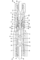
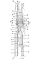
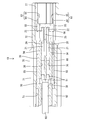
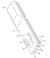
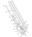
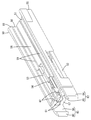
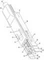
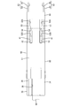
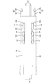
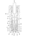
- Example 1 of this invention it is a perspective view which shows the state by which the female connector and the male connector were normally fitted. It is sectional drawing which shows the state by which the female connector and the male connector were normally fitted. It is sectional drawing which shows the state of the fitting process or detachment
- the male terminal cover is provided with an engaging portion, and the female connector is engaged with the engaging portion in a direction away from the hood portion, and the male terminal is moved away from the hood portion. It is preferable that an engaged portion that displaces the covering toward the protection position is provided.
- the male terminal cover and the male terminal cover are taken out from the male housing after the female connector and the male connector are detached, if the male terminal cover is left in the exposed position, the male tab is There are concerns about interference. Moreover, there is also a problem that the work load is heavy when the operation of displacing the male terminal support to the protected position is performed after the male terminal support and the male terminal covering are taken out.
- the engaged portion engaged with the engaging portion by the detaching operation of the female connector from the hood portion protects the male terminal covering body.
- the male terminal cover can automatically return to the protected position, and the male terminal cover is displaced to the protected position. Special work and jigs can be omitted, and the male tab can be protected quickly.
- One of the male terminal support body and the male terminal cover body is provided with a semi-lock portion that can be bent and deformed, and on the other side, is engaged with the interference portion of the semi-lock portion at the exposed position, and the male terminal cover body It is preferable that a restricting portion for restricting relative displacement to the protection position is provided, and the restricting portion is arranged to be separated from the interference portion when the male terminal covering body is at the protection position.
- the male terminal support and the male terminal cover can be prevented from inadvertently sliding relative to each other.
- the restricting portion is disposed away from the interference portion. Therefore, when the male terminal cover slides relative to the male terminal cover, the male terminal cover is positioned between the male terminal support and the male terminal cover. It is possible to avoid an excessive increase in the frictional resistance and to ensure the smoothness of the relative slide.
- the first embodiment exemplifies a connector constituting a communication system mounted on an automobile, and includes a female connector 100 and a male connector 10 that can be fitted to each other as shown in FIG.
- the male connector 10 includes a male terminal fitting 20, a male terminal support 30, a male terminal covering 50, and a male housing 70.
- the male terminal fitting 20 is supported by the male terminal support 30.
- the male terminal support body 30 and the male terminal covering body 50 are assembled so as to be relatively slidable in the front-rear direction.
- the assembled male terminal support 30 and male terminal cover 50 are inserted into the male housing 70 and accommodated along the front-rear direction.
- the male terminal fitting 20 is integrally formed by bending a conductive metal material or the like, and has a male tab 22 that protrudes from the cylindrical main body portion 21 to the front, as shown in FIG. Is connected to the terminal portion of the cable 90 at the rear of the cable.
- the cable 90 is configured as a twisted pair wire in which two electric wires 91 are twisted in pairs. The two electric wires 91 are twisted back at the portion where the covering 92 is removed, and the male terminal fitting 20 is connected to the portion where the twisting is reversed.
- the male terminal support 30 is a dielectric made of a synthetic resin, and has a rectangular plate-shaped support body 31 that is long in the front-rear direction, as shown in FIGS. As shown in FIG. 7, a housing lock portion 32 protrudes from the front portion of the upper surface of the support main body 31, and a pair of forward restricting portions 33 protrude from the left and right sides of the housing lock portion 32 and rearward.
- standard of the up-down direction in description is based on the state of FIG. 6 in which the male terminal support body 30 and the male terminal covering body 50 were accommodated in the male housing 70.
- a pair of rail portions 34 are provided to extend in the front-rear direction at both left and right end portions, and a partition portion 35 is provided to extend in the front-rear direction at the center portion on the left and right. ing.
- a pair of left and right male terminal insertion spaces 36 are defined between the rail portions 34, the partition portions 35, and the support body 31.
- the male terminal fitting 20 is inserted and accommodated in each male terminal insertion space 36 of the male terminal support 30.
- a terminal retaining portion 37 for preventing the main body portion 21 of the male terminal fitting 20 accommodated in each male terminal insertion space 36 is provided on the lower surface of the support main body 31 .
- a support piece 38 that can support the male tab 22 of the terminal fitting 20 is provided in a projecting manner.
- one cable end insertion space 39 is defined between the support body 31 and each rail part 34 and behind the partition part 35.
- the cable end insertion space 39 accommodates the end portion of the covering 92 of the cable 90. Since each male terminal insertion space 36 is located immediately in front of the cable end insertion space 39, the length of the untwisted portion from the end of the covering 92 of the cable 90 to the connection to the male terminal fitting 20 is shortened. The communication performance can be improved.
- the male terminal fitting 20 inserted into each male terminal insertion space 36 is substantially fixed to the male terminal support 30 and behaves integrally with the male terminal support 30.
- a pair of rectangular plate-like restricting portions 41 are provided protruding downward from the lower end front portion of each rail portion 34. Further, a guide groove 42 having a concave section is provided on the left and right outer surfaces of each rail portion 34 so as to extend in the front-rear direction.
- the male terminal cover 50 is a dielectric made of a synthetic resin, and has a rectangular plate-shaped cover main body 51 that is long in the front-rear direction, as shown in FIGS. As shown in FIG. 9, a pair of through grooves 52 extending in the front-rear direction are provided through the left and right ends of the covering main body 51 so as to penetrate therethrough. The left and right outer ends of each through groove 52 are partitioned by a pair of semi-lock portions 53 in the covering body 51. Each semi-lock portion 53 has a doubly-supported beam shape elongated in the front-rear direction, and has an interference portion 54 that protrudes so as to narrow the width of the through groove 52 at a position near the front end. Each semi-lock portion 53 is bent and deformed outwardly like a bow when the restricting portion 41 interferes with the interference portion 54, and allows relative displacement of the restricting portion 41 in the through groove 52.
- each interference part 54 is tapered in the front-rear direction, and the rear surface of each interference part 54 is disposed substantially at right angles to the front-rear direction.
- the front groove portion 52A has a sufficiently shorter front and rear length than the rear groove portion 52B, and has an opening length substantially the same as the front and rear length of the interference portion 54. Formed (see FIG. 14).
- a pair of side wall portions 55 are provided to extend in the front-rear direction at both left and right end portions, and a partition wall portion 56 is provided to extend in the front-rear direction at the left-right center portion.
- the front wall part 57 connected to each front end of each side wall part 55 and the partition part 56 is provided in the front end part so that it may extend in the left-right direction.
- Each side wall portion 55 is cut out at a portion corresponding to each semi-lock portion 53 and is located outside each semi-lock portion 53 in the left-right direction.
- Each semi-lock portion 53 can be bent and deformed into a space reserved inward from the outer surface of each side wall portion 55.
- a guide portion 58 is provided on the upper end portion of each side wall portion 55 so as to protrude inward. As shown in FIG. 4, each guide portion 58 enters each guide groove 42 and is slidable in each guide groove 42, thereby enabling relative sliding of the male terminal support body 30 and the male terminal covering body 50. .
- the male terminal covering body 50 has a pair of left and right covering spaces 59 defined between the side wall portions 55, the partition wall portions 56, the front wall portion 57, and the covering body 51.
- each covering space 59 the male terminal fitting 20 is disposed so as to be covered.
- the front wall portion 57 is provided with a pair of left and right tab insertion openings 61 through which the male tabs 22 of the male terminal fittings 20 can penetrate.
- Each tab insertion opening 61 communicates with a slit groove 62 that extends in the vertical direction and opens at the upper end of the front wall portion 57.
- Each slit groove 62 serves as a passage when the male tab 22 of each male terminal fitting 20 is introduced into each tab insertion opening 61, and as shown in FIG. 15, each support piece of the male terminal support 30 is provided inside. 38 enters.
- a pair of engaging portions 63 are provided at the left and right ends of the front wall portion 57 so as to extend forward.
- Each engagement portion 63 is connected to the front surface of the front wall portion 57 over substantially the entire length in the vertical direction, and extends in the vertical direction of the front wall portion 57 (also the vertical size of each side wall portion 55).
- 64 and a claw-shaped latching portion 65 projecting inward from the front end portion of the arm portion 64.
- the front outer surface of each arm portion 64 is inclined inwardly in a tapered shape.
- each latching portion 65 are inclined in a taper shape with respect to the front-rear direction.
- the front slope of each latching portion 65 is formed with a smaller angle of inclination with respect to the front-rear direction and longer in the front-rear direction than the rear slope of each latching portion 65.
- the upper and lower portions of the front end of each engaging portion 63 are notched in a tapered shape.
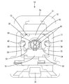
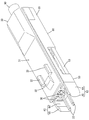
- the male housing 70 is made of a synthetic resin, and as shown in FIGS. 5 and 6, the male housing 70 has a cylindrical shape penetrating in the front-rear direction as a whole.
- the housing 71 is connected to the housing 71 and protrudes forward. And a hood portion 72.
- the housing part 71 has a male unit housing space 73 that penetrates in the front-rear direction.
- a lance 74 that can be flexibly deformed is provided on the inner wall upper surface of the accommodating portion 71 (the inner wall upper surface of the male unit accommodating space 73) so as to protrude forward in a cantilever shape.
- a claw-like locking projection 75 is provided at the front end of the lance 74 so as to protrude downward.
- An attachment portion 76 for attaching to a bracket on the vehicle body side (not shown) is provided on the lower surface side of the housing portion 71.
- the hood part 72 has a fitting space 77 that is shorter in the front-rear direction than the housing part 71 and is slightly larger in the radial direction and penetrates in the front-rear direction and communicates with the male unit housing space 73.
- a claw-shaped lock portion 78 is provided on the front end portion of the inner surface of the upper wall of the hood portion 72 so as to protrude downward.
- the female connector 100 includes a female terminal fitting 120, a female terminal support 130, a female terminal covering 150, and a female housing 170. Similar to the male terminal fitting 20, the female terminal fitting 120 is connected in a pair to the end of the electric wire 91 formed of the twisted pair wire of the cable 190.
- the female terminal fitting 120 has a cylindrical portion 121 that receives the male tab 22 of the male terminal fitting 20, and has a contact portion 122 that elastically contacts the male tab 22 inside the cylindrical portion 121.
- the female terminal support 130 and the female terminal cover 150 are dielectrics made of synthetic resin, and the basic structure is the same as that of the male terminal support 30 and the male terminal cover 50 described above.
- the female terminal support 130 supports each female terminal fitting 120, and the female terminal covering 150 is assembled to the female terminal support 130 from above so as to cover each female terminal fitting 120.
- the female terminal support 130 and the female terminal cover 150 are not configured to slide relative to each other.
- the female terminal support 130 has a front wall 131 capable of pre-stopping each female terminal fitting 120.
- the front wall 131 is provided with a pair of tab through holes 132 through which the male tabs 22 of the male terminal fittings 20 penetrate.
- the front surface of the front wall 131 is disposed along the vertical direction at substantially the same longitudinal position as the front end of the female housing 170 in a state where the female terminal support 130 is accommodated in a female unit accommodating space 171 described later, as shown in FIG.
- the pressing surface 133 is configured to press the male terminal covering body 50 in the fitting process of the female connector 100 and the male connector 10.
- the female terminal covering 150 has an upper plate portion 151 that covers the upper portion of the female terminal support 130 and a pair of side plate portions 152 that cover both sides of the female terminal support 130. .
- Each side plate 152 is provided with a pair of engaged portions 153.
- Each engaged portion 153 has a notch groove shape extending in the vertical direction and opening upward at the front portion of each side plate portion 152, and is configured to penetrate each side plate portion 152 in the plate thickness direction.
- each engaged portion 153 has a cross-sectional shape that expands in a substantially tapered shape from the inner surface to the outer surface of each side plate portion 152, and the inclination angle of the rear slope with respect to the front-rear direction is smaller than that of the front slope. The rear slope is longer than the front slope.
- each engaged portion 153 has a cross-sectional shape corresponding to each latching portion 65 (see FIGS. 2 and 3).
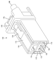
- the female housing 170 is made of a synthetic resin, and as shown in FIG. 17, a female unit housing space 171 capable of housing the female terminal support 130 and the female terminal covering body 150 is provided through the inside in the front-rear direction. ing.
- a pair of recesses 172 are provided on both side surfaces of the inner wall of the female housing 170 (both side surfaces of the inner wall of the female unit housing space 171).
- the inside of each concave portion 172 is a space that allows the bending operation of each engaging portion 63 in the process of fitting and releasing the female connector 100 and the male connector 10 described later.
- the female housing 170 is provided with a deformable lock arm 173 extending rearward from the front end portion of the outer surface of the upper wall.
- the lock arm 173 is provided with a lock protrusion 174 that protrudes upward, and a release operation portion 176 that is provided one step higher behind the lock protrusion 174.
- the female housing 170 is provided with an arch portion 175 that surrounds the periphery of the release operation portion 176.
- the male terminal fitting 20 is accommodated and held in each male terminal insertion space 36 of the male terminal support 30.
- the male terminal covering 50 is put on the male terminal support 30.
- the guide portions 58 of the side wall portions 55 of the male terminal cover 50 elastically enter the guide grooves 42 of the rail portions 34 of the male terminal support 30, so that the male terminal support 30 and the male terminal cover 50 are It is designed to be kept in a withdrawal restriction state.
- each restricting portion 41 of the male terminal support 30 enters the rear end side of the rear groove portion 52 ⁇ / b> B of each through groove 52 of the male terminal covering body 50, and each restricting portion 41 passes through each through portion. Due to the frictional resistance with the groove surface of the groove 52, it is arranged in a movement restricted state in the front-rear direction.
- the male tab 22 of each male terminal fitting 20 protrudes forward of the male terminal support 30, but the lower, both sides and front of each male tab 22 are male terminal covering bodies.
- 50 is covered with a covering main body 51, both side wall portions 55 and a front wall portion 57 (hereinafter referred to as a covering portion 66).
- the male terminal covering 50 is retained in a protected position that protects the male tab 22 against the male terminal support 30.
- the male tab 22 of each male terminal fitting 20 is protected from external foreign matter by the covering portion 66.
- male unit 80 the assembled male terminal support body 30 and male terminal covering body 50 (hereinafter referred to as male unit 80) are inserted into the male unit housing space 73 of the housing portion 71 of the male housing 70.
- the male unit 80 may be pushed into the male unit accommodating space 73 of the accommodating portion 71 while holding the cable 90 extending rearward from the male terminal support 30. Since the male tab 22 of each male terminal fitting 20 is covered with the covering portion 66 of the male terminal covering 50 in the protected position, the wall surface of the male housing 70 does not directly interfere with each male tab 22, Each male tab 22 is prevented from being broken or broken.
- the housing lock portion 32 of the male terminal support 30 presses and deforms the lance 74, and the male terminal support 30 further enters the male unit accommodation space 73.
- the lance 74 is elastically restored, and the locking projection 75 is arranged to be locked to the housing lock portion 32 as shown in FIG.
- the forward restricting portions 33 of the male terminal support 30 abut against stoppers (not shown) provided on the male housing 70, so that the transition of the male terminal support 30 toward the hood 72 is restricted.
- the male terminal support 30 is held in the movement restricted state in the front-rear direction in the male unit housing space 73.
- the covering portion 66 of the male terminal covering 50 is disposed so as to protrude into the fitting space 77 of the hood portion 72. Accordingly, the male tabs 22 that similarly project into the fitting space 77 are also protected in the fitting space 77 by the covering portion 66.
- the male terminal cover 50 is disposed so as to be slidable relative to the male terminal support 30 in the male unit housing space 73 and the fitting space 77.
- a female terminal cover 150 is placed on a female terminal support 130 that supports a female terminal fitting 120, and the female terminal support 130 and the female terminal cover 150 (hereinafter referred to as a female unit 180). 16 is inserted and held in the female unit accommodating space 171 of the female housing 170, thereby assembling the female connector 100 shown in FIG.
- the female housing 170 of the female connector 100 is inserted into the fitting space 77 of the hood portion 72 of the male connector 10.
- the front wall portion 57 contacts the front wall portion 57 in a face-to-face state.
- the latching portion 65 of each engaging portion 63 is elastically fitted into each engaged portion 153, and each engaged portion 153 holds the covering portion 66 so that each engaged portion 63 holds the covering portion 66.
- Engage with As a result, the female unit 180 and the male terminal covering 50 are substantially connected.
- each restricting portion 41 of the male terminal support 30 is displaced toward the front groove portion 52 ⁇ / b> A of each through groove 52 of the male terminal covering body 50.
- each restricting portion 41 elastically crosses each interference portion 54 and is inserted into the front groove portion 52A of each through groove 52 in a fitted state.
- the male terminal covering body 50 reaches the exposed position with respect to the male terminal support body 30 (see FIG. 14).
- Each restricting portion 41 is arranged in a movement restricting state in the front-rear direction between each through groove 52 and each interference portion 54 at the exposed position.
- the pressing surface 133 of the female unit 180 abuts on the male unit 80 including the male terminal support 30 in a face-to-face state.
- the male tab 22 of each male terminal fitting 20 enters the female unit 180 from each tab insertion opening 61 through each tab through-opening 132 and is inserted and connected to the cylindrical portion 121 of each female terminal fitting 120.
- the release operation portion 176 is pressed from above, and the lock arm 173 is bent and deformed in the unlocking direction. Be made.
- the female connector 100 and the male connector 10 are pulled apart from each other in a state where the lock arm 173 and the lock portion 78 are unlocked.
- each restricting portion 41 gets over each interfering portion 54, the engaged state between each engaging portion 63 and each engaged portion 153 is maintained, and the male terminal covering 50 follows the female connector 100 to be protected. Displace towards the position. During this time, each restricting portion 41 is smoothly displaced toward the rear end side of the rear groove portion 52B of each through groove 52 without interfering with each interference portion 54.
- each restricting portion 41 reaches a position where it abuts on the rear end of the rear groove portion 52B of each through groove 52, the follower displacement of the male terminal covering 50 is further increased. Is regulated (see FIG. 12). Accordingly, each engaging portion 63 is bent and deformed in a direction away from each engaged portion 153, and the connection state between the female connector 100 and the male terminal covering body 50 is released.
- the male terminal covering body 50 is disposed in the male housing 70 in a state where the male terminal covering body 50 is returned to the protected position with respect to the male terminal support body 30 again.
- the lance 74 is bent and deformed in the direction to release the engagement with the housing lock portion 32, and in this state, the cable 90 connected to the male terminal fitting 20 is pulled rearward, whereby the male terminal covering body.
- the male unit 80 having 50 in the protected position is taken out from the hood portion 72. Therefore, when the male unit 80 is taken out from the hood portion 72, the male tab 22 is prevented from interfering with the male housing 70 and the like to be broken or damaged. Moreover, after taking out the male unit 80 from the food
- the male tab 22 is protected by the covering portion 66 of the male terminal covering 50 when the male terminal covering 50 is in the protected position. Breakage and damage can be prevented.
- the covering portion 66 of the male terminal covering body 50 is retracted to the exposed position so that the female terminal fitting 120 and the male terminal fitting 20 can be connected.
- the covering portion 66 of the male terminal covering 50 is pressed to the exposed position by being pressed by the pressing surface 133 of the female connector 100 in the process in which the female connector 100 is fitted into the fitting space 77 of the hood portion 72. It is displaced towards. Accordingly, the displacement operation of the male terminal support 30 to the exposed position is linked to the fitting operation of the female connector 100 and the male connector 10, and a special operation for displacing the male terminal support 30 to the exposed position is performed.
- tool can be abbreviate
- the male terminal cover 50 is provided with an engaging portion 63
- the female connector 100 is provided with an engaged portion 153 that engages with the engaging portion 63 in a direction away from the hood portion 72.
- the engaged portion 153 engaged with the engaging portion 63 is displaced toward the protected position by the detachment operation of the female connector 100 from the hood portion 72. Can be made.
- the male terminal covering 50 can automatically return to the protected position, and the special operation or treatment for displacing the male terminal covering 50 to the protected position is possible.
- the tool can be omitted and the male tab 22 can be protected quickly.
- the male terminal cover 50 is provided with a semi-lock part 53 that can be bent and deformed.
- the male terminal cover 50 is locked to the interference part 54 of the semi-lock part 53 at the exposed position, and the male terminal cover 50 is moved to the protected position. Since the restricting portion 41 that restricts the relative displacement is provided, the male terminal support body 30 and the male terminal cover body 50 are prevented from accidentally sliding relative to each other when the male terminal cover body 50 is in the exposed position. be able to.
- the restricting portion 41 is disposed away from the interference portion 54 when the male terminal covering 50 is in the protected position, when the male terminal covering 50 is slid relative to the male terminal covering 50, It is possible to avoid excessive frictional resistance generated between the terminal covering body 50 and the smoothness of the relative slide can be ensured.
- the male terminal support body is disposed on the upper side and the male terminal covering body is disposed on the lower side with respect to the male housing.
- the male terminal support body is disposed on the male housing. May be arranged on the lower side and the male terminal cover on the upper side. Further, the male terminal support and the male terminal covering may be arranged on both the left and right sides with respect to the male housing. The same applies to the female housing, the female terminal support and the female terminal covering.
- the pressing surface should just be arrange
- the semi-lock portion is provided on the male terminal cover and the restricting portion is provided on the male terminal support. On the contrary, the semi-lock portion is provided on the male terminal support. The restricting portion may be provided on the male terminal cover.
- the engaging portion of the terminal cover body has a deformable shape having an arm portion.
- the engaged portion of the female connector has an arm portion. You may be in the form which can be bent.
- the engaged portion only needs to be disposed at a position that can be engaged with the engaging portion of the terminal covering body, and may be provided, for example, on the female terminal support or the female housing depending on the structure. .
Landscapes
- Connector Housings Or Holding Contact Members (AREA)
Priority Applications (3)
| Application Number | Priority Date | Filing Date | Title |
|---|---|---|---|
| US16/495,252 US10714863B2 (en) | 2017-03-21 | 2018-02-28 | Connector |
| DE112018001490.8T DE112018001490B4 (de) | 2017-03-21 | 2018-02-28 | Verbinder |
| CN201880019185.7A CN110462940B (zh) | 2017-03-21 | 2018-02-28 | 连接器 |
Applications Claiming Priority (2)
| Application Number | Priority Date | Filing Date | Title |
|---|---|---|---|
| JP2017-053950 | 2017-03-21 | ||
| JP2017053950A JP6829816B2 (ja) | 2017-03-21 | 2017-03-21 | コネクタ |
Publications (1)
| Publication Number | Publication Date |
|---|---|
| WO2018173658A1 true WO2018173658A1 (ja) | 2018-09-27 |
Family
ID=63585216
Family Applications (1)
| Application Number | Title | Priority Date | Filing Date |
|---|---|---|---|
| PCT/JP2018/007385 Ceased WO2018173658A1 (ja) | 2017-03-21 | 2018-02-28 | コネクタ |
Country Status (5)
| Country | Link |
|---|---|
| US (1) | US10714863B2 (enExample) |
| JP (1) | JP6829816B2 (enExample) |
| CN (1) | CN110462940B (enExample) |
| DE (1) | DE112018001490B4 (enExample) |
| WO (1) | WO2018173658A1 (enExample) |
Families Citing this family (4)
| Publication number | Priority date | Publication date | Assignee | Title |
|---|---|---|---|---|
| JP6575546B2 (ja) * | 2017-03-15 | 2019-09-18 | 株式会社オートネットワーク技術研究所 | コネクタ |
| JP7303985B2 (ja) * | 2019-12-02 | 2023-07-06 | 株式会社オートネットワーク技術研究所 | コネクタ |
| JP7359058B2 (ja) * | 2020-03-27 | 2023-10-11 | 住友電装株式会社 | 端子カバー |
| JP7480718B2 (ja) * | 2021-01-25 | 2024-05-10 | 住友電装株式会社 | コネクタ |
Citations (2)
| Publication number | Priority date | Publication date | Assignee | Title |
|---|---|---|---|---|
| JPS52119090U (enExample) * | 1976-03-08 | 1977-09-09 | ||
| JP2015090786A (ja) * | 2013-11-06 | 2015-05-11 | タイコエレクトロニクスジャパン合同会社 | 端子金具、及び、それを備える電気コネクタ |
Family Cites Families (15)
| Publication number | Priority date | Publication date | Assignee | Title |
|---|---|---|---|---|
| NL7203081A (enExample) * | 1971-12-21 | 1973-06-25 | ||
| JPS49138392U (enExample) * | 1973-03-29 | 1974-11-28 | ||
| JPS5811080B2 (ja) | 1976-03-31 | 1983-03-01 | 株式会社島津製作所 | X線装置の管電圧調整装置 |
| CN2049411U (zh) * | 1988-12-22 | 1989-12-13 | 张毅 | 安全电插头 |
| JPH06333629A (ja) | 1993-05-25 | 1994-12-02 | Yazaki Corp | シールド線用コネクタ |
| JP3804524B2 (ja) * | 2001-12-07 | 2006-08-02 | 住友電装株式会社 | コネクタ |
| JP2004355969A (ja) * | 2003-05-29 | 2004-12-16 | Sumitomo Wiring Syst Ltd | コネクタ |
| CN2724242Y (zh) * | 2004-08-09 | 2005-09-07 | 刘景霞 | 直入式防触防脱安全插座 |
| JP4517940B2 (ja) * | 2005-05-27 | 2010-08-04 | 住友電装株式会社 | コネクタ |
| CN200959407Y (zh) * | 2006-04-01 | 2007-10-10 | 胡志荣 | 二极无接地固定扁形防触电电源插头 |
| TWM302066U (en) * | 2006-06-22 | 2006-12-01 | Quanta Comp Inc | Length changeable dummy card |
| JP2008130244A (ja) * | 2006-11-16 | 2008-06-05 | Sumitomo Wiring Syst Ltd | コネクタ |
| FR2982710A1 (fr) * | 2011-11-15 | 2013-05-17 | Schneider Electric Ind Sas | Ensemble de prises electriques |
| US9520669B2 (en) * | 2014-05-19 | 2016-12-13 | Yazaki North America, Inc. | Connector assembly with male terminal protector |
| JP6570553B2 (ja) | 2017-01-13 | 2019-09-04 | 株式会社オートネットワーク技術研究所 | コネクタ |
-
2017
- 2017-03-21 JP JP2017053950A patent/JP6829816B2/ja active Active
-
2018
- 2018-02-28 CN CN201880019185.7A patent/CN110462940B/zh active Active
- 2018-02-28 DE DE112018001490.8T patent/DE112018001490B4/de active Active
- 2018-02-28 US US16/495,252 patent/US10714863B2/en active Active
- 2018-02-28 WO PCT/JP2018/007385 patent/WO2018173658A1/ja not_active Ceased
Patent Citations (2)
| Publication number | Priority date | Publication date | Assignee | Title |
|---|---|---|---|---|
| JPS52119090U (enExample) * | 1976-03-08 | 1977-09-09 | ||
| JP2015090786A (ja) * | 2013-11-06 | 2015-05-11 | タイコエレクトロニクスジャパン合同会社 | 端子金具、及び、それを備える電気コネクタ |
Also Published As
| Publication number | Publication date |
|---|---|
| US20200091648A1 (en) | 2020-03-19 |
| CN110462940A (zh) | 2019-11-15 |
| US10714863B2 (en) | 2020-07-14 |
| DE112018001490B4 (de) | 2024-08-14 |
| JP6829816B2 (ja) | 2021-02-17 |
| DE112018001490T5 (de) | 2019-12-12 |
| CN110462940B (zh) | 2021-01-26 |
| JP2018156877A (ja) | 2018-10-04 |
Similar Documents
| Publication | Publication Date | Title |
|---|---|---|
| JP6480898B2 (ja) | コネクタ | |
| JP6475669B2 (ja) | コネクタ | |
| JP6760147B2 (ja) | シールド端子及びシールドコネクタ | |
| CN110235317B (zh) | 屏蔽端子 | |
| KR101520585B1 (ko) | 통합 가동 단자 안정기를 구비하는 전기 커넥터 | |
| US20150144396A1 (en) | Connector | |
| WO2018173658A1 (ja) | コネクタ | |
| US9819120B2 (en) | Connector | |
| JP6393301B2 (ja) | コネクタ | |
| CN110235319A (zh) | 屏蔽端子 | |
| JP7207233B2 (ja) | コネクタ | |
| CN110911891A (zh) | 连接器结构 | |
| JP6575546B2 (ja) | コネクタ | |
| WO2021153194A1 (ja) | コネクタ | |
| WO2023153217A1 (ja) | コネクタ | |
| JP7088263B2 (ja) | コネクタ | |
| JP6930561B2 (ja) | コネクタ | |
| JP4768641B2 (ja) | 防水コネクタ | |
| JP2025050229A (ja) | コネクタ | |
| JP2008198392A (ja) | ジョイントコネクタ | |
| JP2017130371A (ja) | コネクタ | |
| JP2005085615A (ja) | リテーナ付き端子収容部材、及び治具 | |
| JP7374564B2 (ja) | コネクタ | |
| JP5104746B2 (ja) | コネクタ | |
| JP6222068B2 (ja) | コネクタ |
Legal Events
| Date | Code | Title | Description |
|---|---|---|---|
| 121 | Ep: the epo has been informed by wipo that ep was designated in this application |
Ref document number: 18770525 Country of ref document: EP Kind code of ref document: A1 |
|
| 122 | Ep: pct application non-entry in european phase |
Ref document number: 18770525 Country of ref document: EP Kind code of ref document: A1 |