WO2018173643A1 - 転倒防止装置 - Google Patents
転倒防止装置 Download PDFInfo
- Publication number
- WO2018173643A1 WO2018173643A1 PCT/JP2018/007096 JP2018007096W WO2018173643A1 WO 2018173643 A1 WO2018173643 A1 WO 2018173643A1 JP 2018007096 W JP2018007096 W JP 2018007096W WO 2018173643 A1 WO2018173643 A1 WO 2018173643A1
- Authority
- WO
- WIPO (PCT)
- Prior art keywords
- damper
- insertion piece
- base
- prevention device
- base portion
- Prior art date
- Legal status (The legal status is an assumption and is not a legal conclusion. Google has not performed a legal analysis and makes no representation as to the accuracy of the status listed.)
- Ceased
Links
Images



Definitions
- the present invention relates to a fall prevention device.
- Patent Document 1 discloses a conventional fall prevention device.
- This overturn prevention device includes a damper and a pair of bases.
- the damper is attached between the upper surface of the furniture installed on the floor and the ceiling.
- the pair of base portions pivotally support both end portions of the damper so as to be rotatable around a rotation axis.
- One base part contacts the upper surface of the furniture, and the other base part contacts the ceiling.
- this overturn prevention device has a jig (angle restriction part) for setting the inclination angle of the damper to an optimum angle.
- This fall prevention device is placed with one damper in contact with the upper surface of the furniture with the damper upright. Then, the jig is placed on the upper surface of the furniture in accordance with the base portion that is in contact with the upper surface of the furniture. Thereafter, the damper is tilted according to the jig so that the damper is at an optimum angle, and the other base portion is brought into contact with the ceiling. Thereafter, the jig is removed from the upper surface of the furniture.
- this fall prevention apparatus can make the damping force of a damper act on furniture, can suppress the inclination of furniture, and can prevent the fall of furniture.
- Patent Document 1 since the overturn prevention device of Patent Document 1 is only provided with a jig, the position of the jig relative to the base portion may be shifted. In other words, it is difficult to mount the fall prevention device between the upper surface of the furniture and the ceiling with an appropriate inclination angle.
- the present invention has been made in view of the above-described conventional situation, and when attaching the fall prevention device, the damper can be easily set to an appropriate inclination angle, and can be easily attached and detached as desired. Providing an overturn prevention device provided with an angle restricting portion is an issue to be solved.
- the fall prevention device of the present invention includes a damper, a first base portion, a second base portion, and an angle restricting portion.
- the damper is attached in a state where the axis is inclined between the upper surface of the article installed on the installation surface and the ceiling.
- the first base portion has a first connection portion that rotatably connects one end portion of the damper around the rotation axis, and abuts on the upper surface of the article.
- the second base portion has a second connecting portion that rotatably connects the other end portion of the damper around the rotation axis, and abuts the ceiling.
- the angle restricting portion is attached to the first base portion and restricts the inclination angle of the damper.
- the first base portion has an insertion hole formed on a side where the damper is inclined with respect to the first coupling portion, and the angle regulating portion is a first insertion piece inserted on the coupling portion side of the insertion hole. And a second insertion piece provided at a predetermined interval with respect to the first insertion piece and inserted on the side away from the first coupling portion of the insertion hole. A claw portion that protrudes toward the connecting portion and engages with the insertion hole is provided.
- the first base portion of the fall prevention device of the present invention may have a wall portion.
- the wall portion may be provided with a locking portion depending from the opening edge of the insertion hole and locked by the claw portion.
- the second insertion piece of the fall prevention device of the present invention has an inclined surface inclined in a direction approaching the first insertion piece toward the tip at the tip in the direction opposite to the protruding direction of the claw of the first insertion piece. Can be provided.
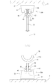
- At least one or more fall prevention devices of the embodiment are attached between the upper surface of the furniture F and the ceiling C.
- the furniture F is installed on the floor surface with the back surface facing a wall surface W extending vertically from a floor surface (not shown).
- the furniture F has a rectangular parallelepiped shape, and has a door, a drawer, etc. (not shown) on the front (right side in FIG. 1), and can store clothes, accessories, and the like inside.
- the furniture F has a rectangular shape in which the horizontal cross-sectional shape is long in the left-right direction (the depth direction in FIG. 1).
- the furniture F may be tilted forward (rightward in FIG. 1) due to shaking such as an earthquake.
- the overturn prevention device includes a damper 10, a pair of base portions 30 ⁇ / b> A and 30 ⁇ / b> B, and an angle restricting portion 70.
- the damper 10 includes a cylinder 11, a rod guide (not shown), a piston (not shown), a rod 13, and two joints 15 provided at both ends. ing.
- the cylinder 11 has a bottomed cylindrical shape.
- the rod guide seals the opening of the cylinder 11.
- the piston is slidably inserted into the cylinder 11.
- the rod 13 has a base end connected to the piston. Further, the rod 13 is inserted through the rod guide, and the tip side protrudes to the outside of the cylinder 11.
- the cylinder 11 encloses hydraulic oil and compressed gas.
- each joint portion 15 is formed by bending a flat metal fitting.
- Each joint portion 15 is connected to the bottom of the cylinder 11 and the tip of the rod 13.
- Each joint portion 15 is formed with a through hole 15A penetrating in a direction perpendicular to the axis of the damper 10 (see FIG. 3).
- the damper 10 is a pressure damper in which the damping force generated during the contraction operation is larger than the damping force generated during the extension operation.
- the extension operation of the damper 10 means an operation in which the length of the rod 13 protruding from the cylinder 11 (the entire length of the damper 10) becomes longer.
- the contraction operation of the damper 10 means an operation in which the length of the rod 13 protruding from the cylinder 11 (the entire length of the damper 10) is shortened.
- the expansion force of the compressed gas sealed in the cylinder 11 acts on the damper 10 in the extending direction. That is, the damper 10 generates a biasing force in the extending direction.
- the mechanism (mechanism) in which the damping force of the damper 10 is generated is a well-known structure, and will not be described.
- the cylinder 11 is partitioned into a rod-side pressure chamber in which the base end portion of the rod 13 is housed and an anti-rod-side pressure chamber by a piston inside.
- the piston is formed with an orifice which is a throttle valve for communicating between the two pressure chambers.
- the orifice functions as a damping force generator that generates a damping force by applying resistance to the flow of hydraulic oil between the rod-side pressure chamber and the non-rod-side pressure chamber accompanying the expansion / contraction operation of the damper 10.
- the piston is formed with a communication passage that communicates between the pressure chambers via a check valve.
- the check valve allows the flow of hydraulic oil from the rod side pressure chamber to the anti rod side pressure chamber, and prevents the reverse flow. For this reason, when the damper 10 is extended, the flow path of the hydraulic oil from the rod-side pressure chamber to the non-rod-side pressure chamber is a path between the orifice and the communication path. On the other hand, during the contraction operation of the damper 10, the flow path of the hydraulic oil from the non-rod side pressure chamber to the rod side pressure chamber is only the orifice. For this reason, the damping force generated during the extension operation of the damper 10 is smaller than the damping force generated during the contraction operation.
- the pair of base portions 30 ⁇ / b> A and 30 ⁇ / b> B is a first base that is one end portion of the damper 10 and that connects a joint portion 15 that is a first connecting portion connected to the bottom of the cylinder 11. It is a part 30 ⁇ / b> A, which is the second base part 30 ⁇ / b> B, which is the other end part of the damper 10 and is connected to the joint part 15, which is a second connecting part connected to the tip part of the rod 13.
- the first base portion 30A is placed in contact with the upper surface of the furniture F, and the second base portion 30B is in contact with the ceiling C.
- the first base portion 30A and the second base portion 30B have the same form and structure.
- each of the base portions 30A and 30B includes a base portion main body 31, a bolt 45 and a nut 47 that are rotating shaft members, a bush 35, and an anti-slip member.
- a portion 37 is provided.
- the base portion main body 31 In a plan view when the first base portion 30A is viewed from above in a state of being placed in contact with the upper surface of the furniture F, the base portion main body 31 has a rectangular outer shape (hereinafter, the base portion main body 31 in the plan view).
- the direction in which the long side extends in the outer shape is referred to as “long side direction”, and the direction in which the short side extends is referred to as “short side direction”.
- the lower end edge of the base body 31 is linearly parallel to the upper surface of the furniture F.
- the upper end edge has an arcuate outer shape that swells upward from both sides of the lower end edge (see FIG. 1).
- the base body 31 has a substantially trapezoidal outer shape in which the upper edge is shorter than the lower edge when the first base 30A is viewed in the long side direction while being placed in contact with the upper surface of the furniture F. (See FIGS. 2 and 3).
- the base portion main body 31 has a long side direction (the left-right direction in FIG. 1 and the depth direction in FIGS. 2 and 3) on the upper surface.
- An elongated groove 41 is formed.
- the groove portion 41 has a bottom surface 41A extending on a horizontal plane, and an inner wall surface 41B rising substantially vertically on both sides of the bottom surface 41A.
- the bottom surface 41 ⁇ / b> A of the groove portion 41 extends substantially at the center in the vertical direction of the base portion main body 31.
- the bottom surface 41A of the groove portion 41 is formed to have a constant width except for a portion where a pair of convex portions 43, 43 described later is formed.
- the groove portion 41 is formed with a pair of convex portions 43 and 43 protruding from the bottom surface 41 ⁇ / b> A of the groove portion 41 and the inner wall surfaces 41 ⁇ / b> B and 41 ⁇ / b> B at the center in the long side direction.
- a space in which the joint portion 15 of the damper 10 and a bush 35 described later are fitted is formed between the convex portions 43 and 43. This space communicates with the groove 41.
- the distance between the inner wall surfaces 43A, 43A of the pair of convex portions 43, 43 (the length in the short side direction of the space) is slightly larger than the length of the bush 35 described later.
- the pair of convex portions 43, 43 has an insertion hole 43B through which a shaft portion 45B of a bolt 45 (described later) is inserted in the upper center in the short side direction.
- the groove 41 is formed with an insertion hole 49 provided through the bottom surface 41A.
- the insertion hole 49 is formed at a predetermined distance from the convex portion 43. The predetermined distance between the insertion hole 49 and the convex portion 43 can be changed as desired.
- the insertion hole 49 has a rectangular shape extending in the width direction of the groove 41 in a plan view from above. In the insertion hole 49, a first insertion piece 72 and a second insertion piece 77 provided in an angle restricting portion 70 described later are inserted.
- the insertion hole 49 is provided with a pair of wall portions 49A. These wall portions 49A are suspended from the opening edge 49C of the insertion hole 49 (see FIG. 5). Specifically, these wall portions 49A are provided to hang down from a pair of opposite sides of the insertion hole 49 opposed in the long side direction. Further, a guide surface 49D is formed on the opposite sides of the wall portions 49A. Further, the opposite sides of the guide surfaces 49D of the wall portions 49A are formed so as to approach the guide surfaces 49D as they go downward from the opening edge 49C of the insertion hole 49. A first inclined surface 49B is formed at the opening edge 49C of the rectangular insertion hole 49 so as to spread upward (see FIG. 5). Further, a tip end surface 49E extending in the horizontal direction is formed at the lower end of the wall portion 49A.
- the base portion main body 31 is a central portion in the long side direction and on both sides of the groove portion 41.
- a recess 42 is formed.
- the recess 42 is open outward in the upward direction and the short side direction.
- an insertion hole 43 ⁇ / b> B penetrating the convex portion 43 is opened in the side surface of the hollow portion 42.
- a head 45A of a bolt 45 described later and a nut 47 screwed into the bolt 45 are arranged in the recess 42.
- this hollow part 42 is formed so that it may expand in a long side direction as it goes upwards. Thereby, it is easy to fit the tool to the head 45A of the bolt 45 and the nut 47 from above.
- the base part main body 31 is a cavity as shown in FIGS.
- the base portion main body 31 opens downward in the first base portion 30A in a state where it is placed in contact with the upper surface of the furniture F.
- the rotating shaft member is composed of a bolt 45 inserted from one of the insertion holes 43B of the base body 31 and a nut 47 screwed into the shaft 45B of the bolt 45. ing.
- the central axis of the bolt 45 becomes the rotation axis of the damper 10 in each base portion 30A, 30B.
- a configuration may be adopted in which a cylindrical pin (pin) is used instead of the bolt 45 and a push nut is used instead of the nut 47.
- the bush 35 is substantially cylindrical as shown in FIG.
- the bush 35 is an elastic body.
- the length of the bush 35 is slightly smaller than the interval between the inner wall surfaces 43A and 43A of the pair of convex portions 43 and 43 provided on the base portion main body 31.
- the bush 35 is formed with a recess 35 ⁇ / b> A that goes around the outer peripheral surface of the central portion.
- the outer diameter of the recess 35 ⁇ / b> A is slightly smaller than the inner diameter of the through hole 15 ⁇ / b> A formed in the joint portion 15 of the damper 10.
- the outer diameter of the portion rising from both ends of the recess 35 ⁇ / b> A of the bush 35 is larger than the inner diameter of the through hole 15 ⁇ / b> A formed in the joint portion 15 of the damper 10. Moreover, the outer peripheral surface 35B of the both ends of the bush 35 is reduced in diameter outward. For this reason, the bush 35 is inserted into the through hole 15 ⁇ / b> A formed in the joint portion 15 of the damper 10 while being elastically deformed. The bush 35 is attached to the joint portion 15 of the damper 10 with the recess 35A fitted in the through hole 15A.
- the inner diameter of the bush 35 is slightly larger than the outer diameter of the shaft part 45B of the bolt 45. Further, the bush 35 has inner peripheral surfaces 35C at both ends that are expanded in the outward direction. For this reason, the bush 35 is rotatable around the shaft portion 45 ⁇ / b> B of the bolt 45. Further, the bush 35 can be inclined with respect to the shaft portion 45B of the bolt 45 as long as the inner peripheral surfaces 35C of both end portions whose diameters have been expanded come into contact with the outer peripheral surface of the shaft portion 45B of the bolt 45. That is, the damper 10 having the bush 35 attached to the joint portion 15 is rotatable around the shaft portion 45B of the bolt 45 and is swingable in a direction crossing the rotation direction. Specifically, the rocking occurs due to the dimensional allowance and the diameter increase of the inner peripheral surface 35C. Furthermore, the elastic deformation of the bush 35 allows the damper 10 to swing more greatly in the direction crossing the rotational direction.
- the anti-slip portion 37 has a similar (rectangular) outer shape slightly larger than the outer shape of the base portion main body 31.
- the anti-slip portion 37 is made of rubber, flexible thermoplastic resin, or the like. Further, the anti-slip portion 37 is fitted into the lower end opening of the base portion main body 31 in the first base portion 30 ⁇ / b> A in a state of being placed in contact with the upper surface of the furniture F.
- skid part 37 is a substantially flat plate. Specifically, the anti-slip portion 37 is formed such that the upper surface of the furniture F or the surface that contacts the ceiling C is flat.
- bushes 35 are fitted into the through holes 15A formed in the two joint portions 15 provided at both ends of the damper 10, and the bushes 35 are attached to the joint portions 15 of the damper 10.
- one of the joint portions 15 of the damper 10 to which the bush 35 is attached is inserted between the pair of convex portions 43 and 43 formed on the base portion main body 31.
- the shaft portion 45B of the bolt 45 is inserted into the insertion hole 43B and the bush 35 of the base portion main body 31, and the nut 47 is screwed into the shaft portion 45B of the bolt 45.
- the base portion main body 31 is connected to one of the joint portions 15 of the damper 10.
- the base portion main body 31 is connected to the other joint portion 15 of the damper 10.
- the head 45 ⁇ / b> A and the nut 47 (both ends of the rotating shaft member) of the bolt 45 are positioned symmetrically with respect to the central axis of the damper 10 in the recess 42 of the base body 31.
- skid part 37 is fitted to each base part main body 31 connected with the both ends of the damper 10, and the assembly
- the damper 10 and the base portions 30 ⁇ / b> A and 30 ⁇ / b> B assembled in this way have a bush 35 that can rotate with respect to the shaft portion 45 ⁇ / b> B of the bolt 45.
- each base part 30A, 30B has the joint part 15, and has connected each of the both ends of the damper 10 so that rotation around the rotating shaft is possible.
- the bush 35 has inner peripheral surfaces 35C at both end portions that are expanded in the outward direction. For this reason, the bush 35 can be tilted with respect to the rotation shaft in a range in which the inner peripheral surfaces 35C of both end portions of the bush 35 whose diameters are expanded are in contact with the outer peripheral surface of the shaft portion 45B of the bolt 45.
- the rocking occurs due to the dimensional allowance and the diameter increase of the inner peripheral surface 35C.
- the bush 35 is an elastic body, and the damper 10 can swing more greatly in the direction intersecting the rotation direction by being elastically deformed.
- the damper 10 connected to each of the base portions 30A and 30B can swing in a direction crossing the rotation direction.
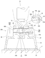
- the angle restricting portion 70 is detachably attached to the first base portion 30A as shown in FIGS. For this reason, this fall prevention device can be prevented from becoming bulky by removing the angle restricting portion 70 from the first base portion 30A during packaging or the like.
- the angle restricting portion 70 is attached to the first base portion 30A, and is provided with a restricting portion 71 that extends substantially in the vertical direction, and a support portion 73 that is provided at the lower end of the restricting portion 71 and prevents the restricting portion 71 from tilting.
- the first insert piece 72 and the second insert piece 77 are inserted into the insertion hole 49 of the first base portion 30A and the angle restricting portion 70 is attached to the first base portion 30A.
- the regulating part 71 has a columnar shape and extends in the vertical direction. In the state where the angle restricting portion 70 is attached to the first base portion 30A, the restricting portion 71 is formed such that the dimension in the long side direction of the base portion 30A is gradually increased from the upper end toward the lower end.
- the restricting portion 71 is provided with a receiving portion 71A at the upper end in a state where the angle restricting portion 70 is attached to the first base portion 30A placed in contact with the upper surface of the furniture F.
- the receiving portion 71A has a semi-annular shape.
- the receiving portion 71 ⁇ / b> A connects the semicircular annular central portion to the upper end portion of the restricting portion 71.
- the receiving portion 71A extends from the upper end portion of the restricting portion 71 toward the short side direction of the first base portion 30A. However, it extends toward the cylinder 11 of the damper 10.
- 71 A of receiving parts are arrange
- the restricting portion 71 places the damper 10 in a predetermined inclined posture by the cylinder 11 of the damper 10 coming into contact with the receiving portion 71A, and restricts the inclination angle so that the damper 10 does not fall down from the inclined posture.
- the inclination angle of the damper 10 is preferably 15 ° to 25 °. Since the receiving portion 71A does not hold the cylinder 11 firmly, the receiving portion 71A does not restrain the movement of the damper 10 that occurs when the furniture F tilts or shakes due to shaking such as an earthquake.
- the damper 10 when the furniture F is shaken or tilted due to a shake such as an earthquake, the damper 10 is rotatable around the rotation axis with respect to the base portions 30A and 30B. It can swing in a direction that intersects the direction.
- the support portion 73 has a flat plate shape and extends in one direction.
- the direction extending in a flat plate shape is substantially orthogonal to the direction in which the restriction portion 71 extends.
- the support portion 73 is connected to the restricting portion 71 with a flat plate-like one surface coming into contact with the lower end of the restricting portion 71.
- the direction in which the support portion 73 extends is the long side direction in the base portion 30A.
- the first insertion piece 72 and the second insertion piece 77 each have a flat plate shape as shown in FIG.
- the second insertion piece 77 is provided with a predetermined distance from the first insertion piece 72 and hangs down from the other surface of the support portion 73.
- the first insertion piece 72 and the second insertion piece 77 have a flat plate thickness direction oriented in a direction in which the support portion 73 extends in one direction.
- the first insertion piece 72 and the second insertion piece 77 are located on the damper 10 side in a state in which the angle restricting portion 70 is attached to the first base portion 30 ⁇ / b> A, and the second insertion piece 77. Is disposed at a position farther from the damper 10 than the first insertion piece 72.
- the 2nd insertion piece 77 is located in the damper 10 side slightly from the center of the support part 73 extended in one direction. Further, the base end of the first insertion piece 72 with respect to the dimension between the pair of convex portions 43 of the first base portion 30A and the insertion hole 49 in a state where the angle restricting portion 70 is attached to the first base portion 30A. From the base end of the second insertion piece 77 to the other end of the support portion 73 extending in the other direction (right direction in FIG. 5) from the base end of the support portion 73 extending in one direction (left direction in FIG. 5) is small. Is large (see FIG. 5).
- a claw portion 74 is provided at the distal end portion of the first insertion piece 72 depending from the other surface of the support portion 73. Specifically, the claw portion 74 is provided over the entire flat front end edge of the first insertion piece 72 with the angle restricting portion 70 attached to the first base portion 30 ⁇ / b> A. It protrudes toward the joint part 15 side.
- a flat surface 78 that is substantially parallel to the support portion 73 is formed on the flat base end side of the first insertion piece 72.
- the claw portion 74 is formed with a second inclined surface 75 that is inclined so as to approach the flat surface 78 toward the damper 10 side.
- the claw portion 74 is not provided on the second insertion piece 77.
- a third inclined surface 76 that is an inclined surface is formed at the tip of the second insertion piece 77 depending from the other surface of the support portion 73. Specifically, the third inclined surface 76 is provided over the entire front end portion of the surface of the second insertion piece 77 opposite to the direction in which the claw portion 74 protrudes. Further, the third inclined surface 76 is inclined in a direction approaching the first insertion piece 72 toward the tip of the second insertion piece 77. Further, the predetermined interval provided between the first insertion piece 72 and the second insertion piece 77 is larger than the dimension in which the claw portion 74 protrudes from the first insertion piece 72 toward the damper 10.
- the semicircular receiving portion 71A of the restricting portion 71 surrounds a part of the outer periphery of the cylinder 11 of the damper 10, and the other surface of the support portion 73 faces the bottom surface 41A of the groove portion 41 of the first base portion 30A.
- the first insertion piece 72 and the second insertion piece 77 are inserted into the insertion hole 49.
- the second inclined surface 75 of the claw portion 74 of the first insertion piece 72 and the third inclined surface 76 of the second insertion piece 77 abut on the first inclined surface 49B of the insertion hole 49, thereby causing the insertion hole 49.
- the first insertion piece 72 and the second insertion piece 77 are guided.
- the distal end portion of the first insertion piece 72 becomes the second insertion piece 77.
- Side in the right direction in FIG. 5
- the first insertion piece 72 and the second insertion piece are made while the tips of the claw portions 74 protruding from the first insertion piece 72 toward the damper 10 abut against the guide surface 49D of the wall portion 49A located on the damper 10 side. 77 is inserted into the insertion hole 49.
- the first insertion piece 72 that has been bent toward the second insertion piece 77 is restored to the position before being bent. Then, the flat surface 78 of the claw portion 74 faces (or abuts) the tip surface 49E. At this time, since the first insertion piece 72 and the second insertion piece 77 are arranged along the guide surfaces 49D of the pair of wall portions 49A, the angle restricting portion 70 tilts with respect to the first base portion 30A. Suppress. Thus, the first insertion piece 72 is locked by the distal end surface 49E of the insertion hole 49 and the claw portion 74.
- the front end surface 49E of the wall portion 49A is a locking portion that the claw portion 74 locks.
- the 1st insertion piece 72 and the 2nd insertion piece 77 can be adjusted to desired bending ease by changing each plate
- the dimension from the first insertion piece 72 to one end of the support part 73 extending in one direction is smaller than the dimension between the pair of convex portions 43 of the first base portion 30A and the insertion hole 49, and the second insertion The dimension from the piece 77 to the other end of the support part 73 extending in one direction is large.
- the angle restricting portion 70 can be attached to the first base portion 30A in a predetermined direction.
- the angle restricting portion 70 attached to the first base portion 30A is configured such that, for example, when the receiving portion 71A is pushed away from the damper 10, the claw portion 74 of the first insertion piece 72 becomes the tip surface 49E of the wall portion 49A. Since it is locked to the first base portion 30A, it is difficult to come off. On the other hand, when the receiving portion 71A is pushed in the direction approaching the damper 10, the second insertion piece 77 is not locked to the wall portion 49A, so that the angle restricting portion 70 is easily detached from the first base portion 30A. .
- deviates from 30 A of 1st bases can be adjusted.
- the predetermined interval provided between the first insertion piece 72 and the second insertion piece 77 is also adjusted according to the size of the claw portion 74 protruding from the first insertion piece 72 toward the damper 10.
- the first insertion piece 72 and the second insertion piece 77 of the angle restricting portion 70 are inserted into the insertion hole 49 formed in the base portion main body 31 of the first base portion 30A, and the angle restricting portion is inserted into the first base portion 30A. 70 is attached.
- the first base portion 30A to which the angle restricting portion 70 is attached is placed with the anti-slip portion 37 in contact with the upper surface of the furniture F on the wall surface W side.
- the angle restricting portion 70 is arranged on the front side of the furniture F from the damper 10.
- the shaft portion 45B (rotating shaft) of the bolt 45 of the first base portion 30A is in a direction in which the furniture F is inclined due to shaking such as an earthquake. It extends in the direction perpendicular to. That is, when the furniture F is tilted forward (rightward in FIG. 1) due to shaking such as an earthquake, the first base portion 30A can be kept in contact with the upper surface of the furniture F.
- the base portion 30A is placed on the upper surface of the furniture F.
- the damper 10 of the fall prevention device is compressed.
- the fall prevention device compresses the damper 10 to such an extent that a gap is provided between the second base portion 30B and the ceiling C.
- the damper 10 is inclined so that the cylinder 11 of the damper 10 contacts the receiving portion 71A of the angle restricting portion 70.
- the damper 10 sets the inclination angle to an appropriate angle between 15 ° and 25 ° with respect to the vertical direction.
- the insertion hole 49 is formed on the side where the damper 10 is inclined with respect to the joint portion 15 of the first base portion 30 when the damper 10 is attached with the axis line inclined between the upper surface of the furniture F and the ceiling C. Will be.
- the second base portion 30B is arranged such that the shaft portion 45B (rotation shaft) of the bolt 45 of the second base portion 30B is parallel to the shaft portion 45B (rotation shaft) of the bolt 45 of the first base portion 30A. Correct the direction of. In this state, when the compression of the damper 10 is stopped, the damper 10 is extended by the urging force, and the second base portion 30B comes into contact with the ceiling C (see FIGS. 1 and 2). That is, the base portions 30A and 30B are in contact with the upper surface of the furniture F and the ceiling C, respectively.
- the fall prevention device can attach the damper 10 between the upper surface of the furniture F installed on the installation surface and the ceiling C so that the expansion and contraction direction forms a predetermined angle with respect to the vertical direction. That is, the damper 10 is in a state in which the inclination angle is restricted by the angle restriction part 70 attached to the first base part 30A, and the axis is inclined between the upper surface of the furniture F installed on the installation surface and the ceiling C. Attached to. In addition, after completing the attaching operation, the angle restricting portion 70 may be removed from the first base portion 30A or may be left attached.
- this fall prevention device can incline the damper 10 at an appropriate inclination angle if the first base portion 30A to which the angle restricting portion 70 is attached is placed on the upper surface of the furniture F.
- the fall prevention device can be appropriately attached between the upper surface of the furniture F and the ceiling C only by maintaining the angle and bringing the second base portion 30B into contact with the ceiling C.
- the axis of the damper 10 extending from the ceiling C side to the upper surface side of the furniture F is inclined downward, and an earthquake or the like in a plan view viewed from above.
- the damper 10 is attached in a state in which the axis of the damper 10 extends in parallel with the direction in which the furniture F is tilted by the shaking (right direction in FIG. 1). For this reason, when the furniture F tilts forward (rightward in FIG. 1) due to shaking such as an earthquake and the upper surface of the furniture F approaches the ceiling C, the damper 10 reliably contracts and generates a damping force. Thereby, this fall prevention device can make the damping force which generate
- the angle restricting portion 70 attached to the first base portion 30A placed on the upper surface of the furniture F restricts the inclination angle of the damper 10.
- this fall prevention device can incline the damper 10 at an appropriate inclination angle if the first base portion 30A to which the angle restricting portion 70 is attached is placed on the upper surface of the furniture F.
- the fall prevention device can be appropriately attached between the upper surface of the furniture F and the ceiling C only by maintaining the angle and bringing the second base portion 30B into contact with the ceiling C.
- this overturn prevention device inserts the first insertion piece 72 and the second insertion piece 77 of the angle restricting portion 70 into the insertion hole 49 of the first base portion 30A, and inserts the claw portion 74 of the first insertion piece 72. Locks into the hole 49. Since a predetermined interval is provided between the first insertion piece 72 and the second insertion piece 77, the first insertion piece 72 is inserted when the claw portion 74 of the first insertion piece 72 is inserted into the insertion hole 49. Is inserted into the insertion hole 49 while being bent in a direction approaching the second insertion piece 77. For this reason, this fall prevention device can easily attach the angle restricting portion 70 to the first base portion 30A.
- the insertion hole 49 is formed on the side where the damper 10 is inclined, and the angle restricting portion 70 has the first insertion piece 72 inserted in the insertion hole 49 on the joint portion 15 side. That is, the claw portion 74 is locked in the insertion hole 49 on the joint portion 15 side.
- the damper 10 comes into contact with the angle restricting portion 70 and is inserted when the angle restricting portion 70 is pushed away from the joint portion 15 by the damper 10.
- the claw portions 74 locked in the holes 49 can prevent the angle restricting portion 70 from being unintentionally detached from the first base portion 30A.
- the angle restricting portion 70 is removed from the first base portion 30A, it can be easily removed by inclining the angle restricting portion 70 toward the joint portion 15 side.
- the fall prevention device can easily make the fall prevention device at an appropriate inclination angle, and the angle restricting portion 70 can be easily attached and detached as desired.
- the first base portion 30A of the fall prevention device has a wall portion 49A.
- the wall portion 49 ⁇ / b> A has a distal end surface 49 ⁇ / b> E that hangs down from the opening edge 49 ⁇ / b> C of the insertion hole 49 and that the claw portion 74 engages with.
- this fall prevention device can guide the 1st insertion piece 72 and the 2nd insertion piece 77 by wall part 49A. Thereby, this fall prevention device can regulate the direction of angle regulation part 70 to the 1st base part 30A to a predetermined direction.
- this fall prevention device can latch the claw part 74 of the 1st insertion piece 72 to the front end surface 49E provided in wall part 49A. Thereby, this fall prevention apparatus can change easily the position and shape of the front end surface 49E with the nail
- the second insertion piece 77 of the overturn prevention device is arranged in a direction approaching the first insertion piece 72 toward the tip at the tip of the first insertion piece 72 in the direction opposite to the protruding direction of the claw 74.
- An inclined third inclined surface 76 is provided.
- the fall prevention device inserts the second insertion piece 77 into the insertion hole 49 by the third inclined surface 76 of the second insertion piece 77 when the second insertion piece 77 is inserted into the insertion hole 49 of the first base portion 30A. Good guidance. Thereby, this fall prevention device can attach the angle control part 70 to 30 A of 1st bases easily.
- the fall prevention device is attached to the furniture, but may be attached to an article such as a bookcase or a refrigerator that may fall over due to shaking such as an earthquake.
- the fall prevention device is attached to the furniture placed on the floor with the back face facing the wall, but the furniture placed on the floor without being adjacent to the wall May be attached to.
- each base portion is connected to both ends of the damper so as to be rotatable around the rotation axis and swingable in a direction crossing the rotation direction. It is not necessary to connect, and it is not necessary to connect so that rocking is possible.
- a pressure-effective damper is used.
- a dual-effect damper may be used as long as it exhibits a predetermined damping force during a contracting operation.
- a damper in which hydraulic oil and compressed gas are sealed in a cylinder is used.
- a liquid pressure damper in which another liquid is sealed is used as long as it generates a predetermined damping force during a contracting operation.
- other types of dampers may be used.
- the compressed gas is sealed in the cylinder so that the expansion force of the compressed gas acts in the extension direction.
- the force acting in the extension direction is generated by another method such as a coil spring. May be.
- each base part is not limited to the form of the embodiment.
- the claw portion is provided on the first insertion piece, and the claw portion is locked to the front end surface of the wall portion.
- the penetration that penetrates the front end portion of the first insertion piece in the thickness direction A hole or a depression is provided, and a claw is provided on the wall. And you may latch this nail
Landscapes
- Vibration Prevention Devices (AREA)
- Fluid-Damping Devices (AREA)
Abstract
適切な傾斜角度に容易に取り付けでき、所望に応じて容易に着脱できる角度規制部を備えた転倒防止装置を提供する。 転倒防止装置は、ダンパ(10)が家具(F)の上面と天井(C)との間に軸線が傾斜し、第1ベース部(30A)がダンパ(10)の一端のジョイント部(15)に連結し家具(F)の上面に当接し、第2ベース部(30B)がダンパ(10)の他端のジョイント部(15)に連結し天井(C)に当接し、角度規制部(70)がダンパ(10)の傾斜角度を規制する。第1ベース部(30A)はジョイント部(15)よりダンパ(10)が傾斜する側に挿入孔(49)を有し、角度規制部(70)は挿入孔(49)のジョイント部(15)側に挿入されジョイント部(15)側に突出して挿入孔(49)に係止する爪部(74)を具備する第1挿入片(72)、第1挿入片(72)と所定の間隔を有し挿入孔(49)に挿入される第2挿入片(77)を具備する。
Description
本発明は転倒防止装置に関するものである。
特許文献1は従来の転倒防止装置を開示している。この転倒防止装置はダンパ(damper)と一対のベース(base)部とを備えている。ダンパは床面上に設置された家具の上面と天井との間に取り付けられている。一対のベース部はダンパの両端部のそれぞれを回動軸周りに回動自在に軸支している。一方のベース部は家具の上面に当接し、他方のベース部は天井に当接している。また、この転倒防止装置はダンパの傾斜角度を最適な角度に設定する治具(角度規制部)を有している。
この転倒防止装置はダンパを直立させた状態で家具の上面に一方のベース部を当接させて載置する。そして、治具を家具の上面に当接させたベース部に合わせて家具の上面に載置する。その後、ダンパを治具に合わせて傾けて、ダンパを最適な角度にして、他方のベース部を天井に当接させる。その後、治具を家具の上面から取り外す。
このようにして、家具の上面と天井との間に取り付けられた転倒防止装置は、地震等の揺れによってダンパの回動方向と平行な方向に家具が傾くと、各ベース部に対してダンパが回動軸周りに回動して各ベース部が家具の上面と天井とに当接した状態を維持することができる。よって、この転倒防止装置は、ダンパの減衰力を家具に作用させることができ、家具の傾きを抑制して家具の転倒を防止することができる。
しかし、特許文献1の転倒防止装置は、治具が載置されているのみであるため、ベース部に対する治具の位置がずれるおそれがある。つまり、この転倒防止装置は、ダンパを適切な傾斜角度にして家具の上面と天井との間に取り付けることが難しい。
本発明は、上記従来の実情に鑑みてなされたものであって、転倒防止装置を取り付ける際に、ダンパを適切な傾斜角度に容易することができ、所望に応じて容易に着脱することができる角度規制部を備えた転倒防止装置を提供することを解決すべき課題としている。
本発明の転倒防止装置は、ダンパ、第1ベース部、第2ベース部、及び角度規制部を備えている。ダンパは設置面上に設置された物品の上面と天井との間に軸線が傾斜した状態に取り付けられる。第1ベース部はダンパの一端部を回動軸周りに回動自在に連結する第1連結部を有し物品の上面に当接する。第2ベース部はダンパの他端部を回動軸周りに回動自在に連結する第2連結部を有し、天井に当接する。角度規制部は第1ベース部に取り付けられ、ダンパの傾斜角度を規制する。また、第1ベース部は、第1連結部に対してダンパが傾斜する側に形成される挿入孔を有し、角度規制部は、挿入孔の連結部側に挿入される第1挿入片と、第1挿入片に対して所定の間隔を有して設けられ、挿入孔の第1連結部から離れた側に挿入される第2挿入片とを具備し、第1挿入片は、第1連結部側に突出して挿入孔に係止する爪部を具備している。
本発明の転倒防止装置の第1ベース部は、壁部を有し得る。壁部は挿入孔の開口縁から垂下し、爪部が係止する係止部を具備し得る。
本発明の転倒防止装置の第2挿入片は、第1挿入片の爪部の突出方向とは反対側の方向の先端部に、先端に向かうに従い第1挿入片に近づく方向に傾斜した傾斜面を具備し得る。
本発明の転倒防止装置を具体化した実施形態について、図面を参照しつつ説明する。
<実施形態>
実施形態の転倒防止装置は、図1に示すように、家具Fの上面と天井Cとの間に少なくとも1個以上が取り付けられる。この家具Fは、床面(図示せず)から鉛直方向に伸びた壁面Wに背面を対向させて床面上に設置されている。また、この家具Fは、直方体形状であり、正面(図1における右側面)に図示しない扉や引き出し等を有し、内部に衣類や装身具等を収納することができる。家具Fは、水平断面形状が左右方向(図1において奥行き方向)に長い長方形状である。この家具Fは、転倒防止装置が取り付けられていない場合、地震等の揺れによって、前方向(図1において右方向)に傾いて転倒するおそれがある。
実施形態の転倒防止装置は、図1に示すように、家具Fの上面と天井Cとの間に少なくとも1個以上が取り付けられる。この家具Fは、床面(図示せず)から鉛直方向に伸びた壁面Wに背面を対向させて床面上に設置されている。また、この家具Fは、直方体形状であり、正面(図1における右側面)に図示しない扉や引き出し等を有し、内部に衣類や装身具等を収納することができる。家具Fは、水平断面形状が左右方向(図1において奥行き方向)に長い長方形状である。この家具Fは、転倒防止装置が取り付けられていない場合、地震等の揺れによって、前方向(図1において右方向)に傾いて転倒するおそれがある。
転倒防止装置は、図1及び図2に示すように、ダンパ10、一対のベース部30A,30B、及び角度規制部70を備えている。
ダンパ10は、シリンダ(cylinder)11、図示しないロッドガイド(rod guide)、図示しないピストン(piston)、ロッド(rod)13、及び両端に設けられた2個のジョイント(joint)部15を有している。シリンダ11は有底筒状である。ロッドガイドはシリンダ11の開口部を封鎖している。ピストンはシリンダ11内に摺動自在に挿入されている。ロッド13は基端部がピストンに連結されている。また、ロッド13はロッドガイドを挿通して先端側がシリンダ11の外部へ突出している。シリンダ11は作動油及び圧縮ガスを封入している。各ジョイント部15は、図1~図3に示すように、平板状の金具を折り曲げて形成されている。また、各ジョイント部15はシリンダ11の底部とロッド13の先端部に接続されている。各ジョイント部15はダンパ10の軸線に直交する方向に貫通した貫通孔15Aが形成されている(図3参照。)。
ダンパ10は収縮動作時に発生する減衰力が伸長動作時に発生する減衰力よりも大きい圧効きダンパである。ここで、ダンパ10の伸長動作とは、シリンダ11からロッド13の突出する長さ(ダンパ10の全長)が長くなっていく動作を意味する。また、ダンパ10の収縮動作とは、シリンダ11からロッド13の突出する長さ(ダンパ10の全長)が短くなっていく動作を意味する。また、ダンパ10にはシリンダ11に封入した圧縮ガスの膨張力が伸長方向に働いている。つまり、ダンパ10は伸長方向に付勢力を発生する。
ダンパ10の減衰力が発生するメカニズム(mechanism)は、周知の構造であるため、図示を省略して説明する。シリンダ11は、内部がピストンによって、ロッド13の基端部が収納されているロッド側圧力室と、反ロッド側圧力室とに仕切られている。ピストンには両圧力室間を連通させる絞り弁であるオリフィス(orifice)が形成されている。オリフィスは、ダンパ10の伸縮動作に伴うロッド側圧力室と反ロッド側圧力室との間の作動油の流れに抵抗を付与して減衰力を発生する減衰力発生部として機能する。また、ピストンには逆止弁を介して両圧力室間を連通する連通路が形成されている。逆止弁は、ロッド側圧力室から反ロッド側圧力室への作動油の流れを許容し、その逆の流れを阻止する。このため、ダンパ10の伸長動作時は、ロッド側圧力室から反ロッド側圧力室への作動油の流路経路が、オリフィスと連通路の経路になる。一方、ダンパ10の収縮動作時は、反ロッド側圧力室からロッド側圧力室への作動油の流路経路がオリフィスのみとなる。このため、ダンパ10の伸長動作時に発生する減衰力は、収縮動作時に発生する減衰力よりも小さくなる。
一対のベース部30A,30Bは、図1及び図2に示すように、ダンパ10の一端部であり、シリンダ11の底部に接続された第1連結部であるジョイント部15を連結した第1ベース部30Aであり、ダンパ10の他端部であり、ロッド13の先端部に接続された第2連結部であるジョイント部15を連結した第2ベース部30Bである。第1ベース部30Aは家具Fの上面に当接して載置され、第2ベース部30Bは天井Cに当接する。第1ベース部30A及び第2ベース部30Bは同じ形態及び構造である。各ベース部30A,30Bは、図1~図4に示すように、ベース部本体31、回動軸部材であるボルト(bolt)45及びナット(nut)47、ブッシュ(bush)35、及び滑り止め部37を有している。
家具Fの上面に当接して載置された状態で第1ベース部30Aを上方から見た平面視において、ベース部本体31は長方形状の外形である(以下、この平面視におけるベース部本体31の外形において長辺が延びている方向を「長辺方向」と言い、短辺が延びている方向を「短辺方向」と言う。)。また、家具Fの上面に当接して載置された状態で第1ベース部30Aを短辺方向に見た側面視において、ベース部本体31は、下端縁が家具Fの上面に平行に直線状に伸びており、上端縁が下端縁の両側から上方に膨らんだ円弧状の外形である(図1参照)。また、家具Fの上面に当接して載置された状態で第1ベース部30Aを長辺方向に見た側面視において、ベース部本体31は下端縁よりも上端縁が短いほぼ台形状の外形である(図2、3参照)。
家具Fの上面に当接して載置された状態の第1ベース部30Aにおいて、ベース部本体31には上面に長辺方向(図1における左右方向であり、図2、3における奥行き方向)に伸びた溝部41が形成されている。溝部41は、底面41Aが水平面上に広がり、内壁面41Bが底面41Aの両側にほぼ鉛直方向に立ち上がっている。溝部41の底面41Aはベース部本体31の上下方向のほぼ中央に伸びている。また、溝部41の底面41Aは、後述する一対の凸部43,43が形成されている部分を除き、幅が一定に形成されている。
溝部41には、図4に示すように、長辺方向の中央部に溝部41の底面41A及び両内壁面41B,41Bから突出した一対の凸部43,43が形成されている。これら凸部43,43には、図2、3に示すように、その間にダンパ10のジョイント部15及び後述するブッシュ35が嵌まり込む空間が形成されている。この空間は溝部41に連通している。一対の凸部43,43の内壁面43A,43A同士の間隔(空間の短辺方向の長さ)は後述するブッシュ35の長さよりも僅かに大きい。また、一対の凸部43,43は上部中央に後述するボルト45の軸部45Bが挿通する挿通孔43Bが短辺方向に貫通している。
溝部41は、図4に示すように、底面41Aに貫通して設けられた挿入孔49が形成されている。挿入孔49は凸部43から所定の距離を設けて形成されている。挿入孔49と凸部43との所定の距離は所望に応じて変更自在である。挿入孔49は上方からの平面視において、溝部41の幅方向に伸びた長方形状である。挿入孔49は後述する角度規制部70に設けられた第1挿入片72及び第2挿入片77が挿入される。
また、図1、5に示すように、挿入孔49には一対の壁部49Aが設けられている。これら壁部49Aは挿入孔49の開口縁49Cから垂下している(図5参照。)。具体的には、これら壁部49Aは長辺方向に対向した挿入孔49の対向する一対の辺から垂下して設けられている。また、これら壁部49Aの互いに対向する側には案内面49Dが形成されている。また、これら壁部49Aのそれぞれの案内面49Dの反対側は、挿入孔49の開口縁49Cから下方向に向かうにつれて、それぞれの案内面49Dに近づくように形成されている。また、長方形状をなした挿入孔49の開口縁49Cには、上方向に広がるように第1傾斜面49Bが形成されている(図5参照。)。また、これら壁部49Aの下端は水平方向に伸びる先端面49Eが形成されている。
図4に示すように、家具Fの上面に当接して載置された状態の第1ベース部30Aにおいて、ベース部本体31には、長辺方向の中央部であって、溝部41の両側に窪み部42が形成されている。この窪み部42には上方向と短辺方向の外方向に開口している。また、この窪み部42には凸部43を貫通した挿通孔43Bが側面に開口している。また、この窪み部42は後述するボルト45の頭部45Aと、このボルト45にねじ込まれたナット47のそれぞれが配置される。また、この窪み部42は、上方に向かうにつれて長辺方向に拡がるように形成されている。これにより、ボルト45の頭部45A、及びナット47のそれぞれに上方から工具を嵌合させ易い。
ベース部本体31は、図1、3、5に示すように、空洞である。また、このベース部本体31は、家具Fの上面に当接して載置された状態の第1ベース部30Aにおいて、下方に開口している。
回動軸部材は、図2~4に示すように、ベース部本体31の挿通孔43Bの一方から挿入されたボルト45と、このボルト45の軸部45Bにねじ込まれたナット47とから構成されている。ボルト45の中心軸が各ベース部30A,30Bにおけるダンパ10の回動軸になる。また、ボルト45に替えて円柱状のピン(pin)とし、ナット47に替えてプッシュナット(push nut)とする構成であってもよい。
ブッシュ35は、図3に示すように、ほぼ円筒状である。ブッシュ35は弾性体である。ブッシュ35の長さはベース部本体31に設けられた一対の凸部43,43の内壁面43A,43A同士の間隔よりも僅かに小さい。ブッシュ35には中央部の外周面を一周した凹部35Aが形成されている。この凹部35Aの外径はダンパ10のジョイント部15に形成された貫通孔15Aの内径よりも僅かに小さい。ブッシュ35の凹部35Aの両端から立ち上がった部分の外径はダンパ10のジョイント部15に形成された貫通孔15Aの内径よりも大きい。また、ブッシュ35の両端部の外周面35Bは外方向に縮径している。このため、ブッシュ35はダンパ10のジョイント部15に形成された貫通孔15Aに弾性変形させながら挿入される。そして、ブッシュ35は、貫通孔15Aに凹部35Aが嵌まり込んで、ダンパ10のジョイント部15に取り付けられる。
ブッシュ35は中央部の内径がボルト45の軸部45Bの外径よりも僅かに大きい。また、ブッシュ35は両端部の内周面35Cが外方向に拡径している。このため、このブッシュ35はボルト45の軸部45B周りに回動自在である。また、このブッシュ35は、拡径した両端部の内周面35Cがボルト45の軸部45Bの外周面に当接する範囲で、ボルト45の軸部45Bに対して傾くことができる。つまり、ブッシュ35をジョイント部15に取り付けたダンパ10は、ボルト45の軸部45B周りに回動自在であり、回動方向に交差する方向に揺動自在である。具体的には、寸法上の余裕と内周面35Cの拡径によって揺動する。さらに、ブッシュ35が弾性変形することによって、ダンパ10は回動方向に交差する方向に、より大きく揺動することができる。
滑り止め部37は、図1~図4に示すように、ベース部本体31の外形に対して僅かに大きい相似形(長方形状)の外形である。滑り止め部37はゴム(rubber)や可撓性を有した熱可塑性樹脂等で形成されている。また、滑り止め部37は、家具Fの上面に当接して載置された状態の第1ベース部30Aにおいて、ベース部本体31の下端開口に嵌合される。また、滑り止め部37はほぼ平板である。詳しくは、滑り止め部37は、家具Fの上面又は天井Cに当接する面が平坦に形成されている。
ここで、ダンパ10と各ベース部30A,30Bとの組み付け工程について説明する。
まず、ダンパ10の両端に設けられた2個のジョイント部15に形成された各貫通孔15Aにブッシュ35を嵌め込み、ブッシュ35をダンパ10のジョイント部15に取り付ける。次に、ブッシュ35を取り付けたダンパ10のジョイント部15の一方をベース部本体31に形成された一対の凸部43,43の間に挿入する。そして、ボルト45の軸部45Bをベース部本体31の挿通孔43B及びブッシュ35に挿通させ、ボルト45の軸部45Bにナット47をねじ込む。このようにして、ダンパ10のジョイント部15の一方にベース部本体31を連結する。ダンパ10のジョイント部15の他方も同様にベース部本体31を連結する。この状態で、図3に示すように、ボルト45の頭部45Aとナット47(回動軸部材の両端部)はダンパ10の中心軸に対称な位置でベース部本体31の窪み部42内で露出している。そして、ダンパ10の両端部に連結されたそれぞれのベース部本体31に滑り止め部37を嵌合させて、ダンパ10と各ベース部30A,30Bとの組み付け工程を終了する。
このように組み付けられたダンパ10と各ベース部30A,30Bは、図3に示すように、ボルト45の軸部45Bに対してブッシュ35が回動自在である。このため、各ベース部30A,30Bはジョイント部15を有し、ダンパ10の両端部のそれぞれを回動軸周りに回動自在に連結している。また、ブッシュ35は、両端部の内周面35Cが外方向に拡径している。このため、ブッシュ35の拡径した両端部の内周面35Cがボルト45の軸部45Bの外周面に当接する範囲で、ブッシュ35が回動軸に対して傾くことができる。具体的には、寸法上の余裕と内周面35Cの拡径によって揺動する。さらに、ブッシュ35は、弾性体であり、弾性変形することによって、ダンパ10は回動方向に交差する方向に、より大きく揺動することができる。このように、各ベース部30A,30Bに連結されたダンパ10は回動方向と交差する方向に揺動することができる。
角度規制部70は、図1、2、5に示すように、第1ベース部30Aに着脱自在に取り付けられる。このため、この転倒防止装置は梱包時等に角度規制部70を第1ベース部30Aから取り外すことによって、嵩張らないようにすることができる。角度規制部70は、第1ベース部30Aに取り付けられた状態で、ほぼ鉛直方向に伸びた規制部71と、規制部71の下端に設けられ、規制部71の傾倒を防止する支持部73と、第1ベース部30Aの挿入孔49に挿入し、角度規制部70を第1ベース部30Aに取り付ける第1挿入片72及び第2挿入片77とを有している。
規制部71は、柱状をなして上下方向に伸びている。規制部71は、第1ベース部30Aに角度規制部70を取り付けた状態で、上端から下端に向かうにつれてベース部30Aにおける長辺方向の寸法が徐々に大きく形成されている。規制部71は、家具Fの上面に当接して載置された第1ベース部30Aに角度規制部70を取り付けた状態において、上端部に受け部71Aが設けられている。受け部71Aは半円環状をなしている。受け部71Aは半円環状の中央部を規制部71の上端部に連結している。受け部71Aは、第1ベース部30Aに角度規制部70を取り付けた状態で、半円環状の両端部のそれぞれが規制部71の上端部から第1ベース部30Aにおける短辺方向に向けて伸びつつ、ダンパ10のシリンダ11の方向に向けて伸びている。受け部71Aは、第1ベース部30Aに角度規制部70を取り付けた状態で、半円環状の内側がダンパ10のシリンダ11の外周の一部を囲むように配置される。
規制部71は、ダンパ10のシリンダ11が受け部71Aに当接することによって、ダンパ10を所定の傾斜姿勢にして、ダンパ10がその傾斜姿勢より倒れないように傾斜角度を規制する。ダンパ10の傾斜角度は15°~25°が好ましい。受け部71Aは、シリンダ11をしっかりと保持しないため、地震等の揺れによって家具Fが傾いたり揺れたりした際に生じるダンパ10の動きを拘束しない。つまり、この転倒防止装置は、地震等の揺れによって家具Fが揺れたり、傾いたりした際に、各ベース部30A,30Bに対してダンパ10が回動軸周りに回動自在であり、回動方向に交差する方向に揺動自在である。
支持部73は平板状をなして一方向に伸びている。支持部73は規制部71が伸びる方向に対して平板状に伸びる方向がほぼ直交している。支持部73は規制部71の下端に平板状の一方の面を当接して規制部71に連結されている。支持部73が伸びる方向はベース部30Aにおける長辺方向である。支持部73は、後述する第1挿入片72、及び第2挿入片77が第1ベース部30Aの挿入孔49に挿入されると、ベース部本体31に形成された溝部41の底面41Aに他方の面が当接する。
第1挿入片72及び第2挿入片77は、図5に示すように、それぞれ平板状をなしている。また、第2挿入片77は第1挿入片72に対して所定の間隔を有して設けて、支持部73の他方の面から垂下している。これら第1挿入片72及び第2挿入片77は平板状の板厚方向を支持部73が一方向に伸びる方向に向けている。また、これら第1挿入片72及び第2挿入片77は、第1ベース部30Aに角度規制部70を取り付けた状態で、第1挿入片72がダンパ10側に位置し、第2挿入片77が第1挿入片72よりもダンパ10から離れた位置に配置されている。そして、第2挿入片77は一方向に伸びる支持部73の中央より僅かにダンパ10側に位置している。また、第1ベース部30Aに角度規制部70を取り付けた状態で、第1ベース部30Aの一対の凸部43と挿入孔49との間の寸法に対して、第1挿入片72の基端から一方向(図5において左方向)に伸びる支持部73の一端までの寸法は小さく、第2挿入片77の基端から他方向(図5において右方向)に伸びる支持部73の他端までの寸法は大きい(図5参照。)。
また、支持部73の他方の面から垂下した第1挿入片72の先端部には爪部74が設けられている。具体的には、爪部74は、第1ベース部30Aに角度規制部70を取り付けた状態で、第1挿入片72の平板状の先端縁の全体に亘り設けられ、ダンパ10のシリンダ11のジョイント部15側に向けて突出している。爪部74において、第1挿入片72の平板状の基端側に、支持部73に対してほぼ平行をなした平面78が形成されている。また、爪部74はダンパ10側に向かうに従い平面78に近づくように傾斜した第2傾斜面75が形成されている。爪部74は第2挿入片77には設けられていない。また、支持部73の他方の面から垂下した第2挿入片77の先端部には傾斜面である第3傾斜面76が形成されている。具体的には、第3傾斜面76は、爪部74の突出する方向とは反対側の第2挿入片77の面の先端部の全体に亘り設けられている。また、第3傾斜面76は、第2挿入片77の先端に向かうに従い第1挿入片72に近づく方向に傾斜している。また、第1挿入片72と第2挿入片77との間に設けられた所定の間隔は、第1挿入片72からダンパ10側に爪部74が突出する寸法より大きい。
次に、こうして形成された角度規制部70を第1ベース部30Aに取り付ける取付け方法を説明する。
先ず、規制部71の半円環状の受け部71Aをダンパ10のシリンダ11の外周の一部を囲むようにし、支持部73の他方の面を第1ベース部30Aの溝部41の底面41Aに対向させる。そして、第1挿入片72、及び第2挿入片77を挿入孔49に挿入する。このとき、第1挿入片72の爪部74の第2傾斜面75、及び第2挿入片77の第3傾斜面76が挿入孔49の第1傾斜面49Bに当接することによって、挿入孔49に第1挿入片72、及び第2挿入片77を案内する。
そして、挿入孔49に対して第1挿入片72、及び第2挿入片77を挿入する方向(図5において下方向)に押し込むと、第1挿入片72の先端部が、第2挿入片77側(図5において右方向)に撓み、第1挿入片72及び第2挿入片77の先端部の互いの間の間隔が狭くなる。そして、第1挿入片72からダンパ10側に向けて突出する爪部74の先端がダンパ10側に位置する壁部49Aの案内面49Dに当接しつつ、第1挿入片72及び第2挿入片77が挿入孔49に挿入される。つまり、角度規制部70は、挿入孔49に挿入した際、挿入孔49のジョイント部15側に挿入される第1挿入片72と、挿入孔49のジョイント部15から離れた側に挿入される第2挿入片77とを具備している。
そして、爪部74の平面78の位置が壁部49Aの先端面49Eの位置より下側に到達すると、第2挿入片77側に撓んでいた第1挿入片72が撓む前の位置に復元し、爪部74の平面78が先端面49Eに対向する(又は当接する。)。このとき、第1挿入片72及び第2挿入片77は一対の壁部49Aの案内面49Dに沿うように配置されているため、第1ベース部30Aに対して角度規制部70が傾倒することを抑える。こうして、第1挿入片72は、挿入孔49の先端面49Eと爪部74によって係止する。つまり、壁部49Aの先端面49Eは爪部74が係止する係止部である。なお、第1挿入片72及び第2挿入片77はそれぞれの板厚を変更することによって、所望の撓み易さに調節自在である。
なお、第1ベース部30Aの一対の凸部43と挿入孔49との間の寸法に対して、第1挿入片72から一方向に伸びる支持部73の一端までの寸法は小さく、第2挿入片77から一方向に伸びる支持部73の他端までの寸法は大きい。これにより、第1ベース部30Aに対して一方向に伸びる支持部73の向きを反転させて、角度規制部70を第1ベース部30Aに取り付けようとしても、第1ベース部30Aの一対の凸部43と挿入孔49との間の寸法に対して、第2挿入片77から一方向に伸びる支持部73の他端までの寸法が大きいため、取り付けることができない。これにより、第1ベース部30Aに対する角度規制部70の向きを所定の向きにして取り付けることができる。
こうして第1ベース部30Aに取り付けられた角度規制部70は、例えば、受け部71Aがダンパ10から離れる方向に押された場合、第1挿入片72の爪部74が壁部49Aの先端面49Eに係止しているため、第1ベース部30Aから外れ難い。これに対して、受け部71Aがダンパ10に近づく方向に押された場合、第2挿入片77が壁部49Aに係止していないため、角度規制部70は第1ベース部30Aから外れ易い。なお、爪部74が第1挿入片72からダンパ10側に突出する寸法を調節することによって、角度規制部70の第1ベース部30Aからの外れ易さを調節することができる。この場合、第1挿入片72と第2挿入片77との間に設けられた所定の間隔も、爪部74が第1挿入片72からダンパ10側に突出した寸法に応じて調節する。
次に、この転倒防止装置を壁面Wに背面を対向させて床面上に設置された家具Fの上面と天井Cとの間に取り付ける取付け方法について説明する。
先ず、第1ベース部30Aのベース部本体31に形成された挿入孔49に角度規制部70の第1挿入片72、及び第2挿入片77を挿入し、第1ベース部30Aに角度規制部70を取り付ける。
次に、角度規制部70が取り付けられた第1ベース部30Aを、家具Fの壁面W側の上面に滑り止め部37を当接させて載置する。この際、角度規制部70はダンパ10より家具Fの正面側に配置する。また、第1ベース部30Aを家具Fの上面に載置した状態で、第1ベース部30Aのボルト45の軸部45B(回動軸)は、家具Fが地震等の揺れによって傾く方向に対して直交する方向に伸びている。つまり、地震等の揺れによって家具Fが前方(図1において右方向)に傾いた際に、第1ベース部30Aが家具Fの上面に当接した状態を維持することができるように、第1ベース部30Aは家具Fの上面に載置される。
次に、転倒防止装置のダンパ10を圧縮する。このとき、この転倒防止装置はダンパ10を第2ベース部30Bと天井Cとの間に隙間が設けられる程度圧縮する。そして、ダンパ10のシリンダ11が角度規制部70の受け部71Aに当接するようにダンパ10を傾斜させる。この状態で、ダンパ10は傾斜角度を鉛直方向に対して15°~25°の間の適正な角度に設定する。つまり、挿入孔49はダンパ10を家具Fの上面と天井Cとの間に軸線が傾斜した状態に取り付けた際、第1ベース部30のジョイント部15に対してダンパ10が傾斜する側に形成されていることになる。そして、第2ベース部30Bのボルト45の軸部45B(回動軸)が、第1ベース部30Aのボルト45の軸部45B(回動軸)と平行になるように、第2ベース部30Bの向きを正す。この状態で、ダンパ10の圧縮を止めるとダンパ10が付勢力により伸長し、第2ベース部30Bが天井Cに当接する(図1、2参照。)。つまり、各ベース部30A,30Bは家具Fの上面と天井Cとにそれぞれが当接する。こうして、この転倒防止装置はダンパ10を設置面上に設置された家具Fの上面と天井Cとの間に鉛直方向に対して伸縮方向が所定の角度をなして取り付けることができる。つまり、ダンパ10は、第1ベース部30Aに取り付けられた角度規制部70によって傾斜角度が規制されて、設置面上に設置された家具Fの上面と天井Cとの間に軸線が傾斜した状態に取り付けられる。なお、取り付け作業を完了した後、第1ベース部30Aから角度規制部70を取り外しても良く、取り付けたままにしても良い。
こうして、この転倒防止装置は、角度規制部70が取り付けられた第1ベース部30Aを家具Fの上面に載置すれば、適切な傾斜角度にダンパ10を傾斜させることができ、ダンパ10の傾斜角度を維持して第2ベース部30Bを天井Cに当接させるのみで転倒防止装置を家具Fの上面と天井Cとの間に適切に取り付けることができる。
家具Fの上面と天井Cとの間に取り付けられた転倒防止装置は、天井C側から家具Fの上面側に伸びたダンパ10の軸線が下り傾斜し、かつ上方から見た平面視において地震等の揺れによって家具Fが傾く方向(図1において右方向)と平行にダンパ10の軸線が伸びた状態にダンパ10が取り付けられる。このため、地震等の揺れによって家具Fが前方(図1において右方向)に傾いて、家具Fの上面が天井Cに近づくと、ダンパ10が確実に収縮動作して減衰力を発生する。これにより、この転倒防止装置はダンパ10で発生した減衰力を家具Fに作用させることができる。
このように、この転倒防止装置は、家具Fの上面に載置した第1ベース部30Aに取り付けられた角度規制部70がダンパ10の傾斜角度を規制する。このように、この転倒防止装置は、角度規制部70が取り付けられた第1ベース部30Aを家具Fの上面に載置すれば、適切な傾斜角度にダンパ10を傾斜させることができ、その傾斜角度を維持して第2ベース部30Bを天井Cに当接させるのみで転倒防止装置を家具Fの上面と天井Cとの間に適切に取り付けることができる。
また、この転倒防止装置は角度規制部70の第1挿入片72と第2挿入片77とを第1ベース部30Aの挿入孔49に挿入して、第1挿入片72の爪部74を挿入孔49に係止する。第1挿入片72と第2挿入片77との間に所定の間隔が設けられているため、第1挿入片72の爪部74が挿入孔49に挿入される際に、第1挿入片72が第2挿入片77に近づく方向に撓みつつ挿入孔49に挿入される。このため、この転倒防止装置は角度規制部70を第1ベース部30Aに容易に取り付けることができる。
また、挿入孔49はダンパ10が傾斜する側に形成されており、角度規制部70はジョイント部15側の挿入孔49に第1挿入片72が挿入されている。すなわち、爪部74はジョイント部15側の挿入孔49に係止している。これにより、角度規制部70を第1ベース部30Aに取り付けた後、ダンパ10が角度規制部70に当接し、ダンパ10によって角度規制部70がジョイント部15から離れる方向に押された場合、挿入孔49に係止した爪部74によって、角度規制部70が第1ベース部30Aから意図せずに外れることを防止することができる。これに対して、角度規制部70を第1ベース部30Aから取り外す場合、角度規制部70をジョイント部15側に傾けることによって容易に取り外すことができる。
したがって、この転倒防止装置は当該転倒防止装置を適切な傾斜角度に容易にすることができ、所望に応じて角度規制部70を容易に着脱することができる。
また、この転倒防止装置の第1ベース部30Aは、壁部49Aを有している。壁部49Aは挿入孔49の開口縁49Cから垂下し、爪部74が係止する先端面49Eを具備している。このため、この転倒防止装置は、壁部49Aによって、第1挿入片72及び第2挿入片77を案内することができる。これにより、この転倒防止装置は、第1ベース部30Aに対する角度規制部70の向きを所定の向きに規制することができる。また、この転倒防止装置は壁部49Aに設けられた先端面49Eに第1挿入片72の爪部74を係止することができる。これにより、この転倒防止装置は、第1挿入片72の爪部74と共に先端面49Eの位置や形状を所望に応じて容易に変更することができる。
また、この転倒防止装置の第2挿入片77は、第1挿入片72の爪部74の突出方向とは反対側の方向の先端部に、先端に向かうに従い第1挿入片72に近づく方向に傾斜した第3傾斜面76を具備している。このため、この転倒防止装置は第2挿入片77を第1ベース部30Aの挿入孔49に挿入する際、第2挿入片77の第3傾斜面76によって第2挿入片77を挿入孔49に良好に案内することができる。これにより、この転倒防止装置は角度規制部70を第1ベース部30Aに容易に取り付けることができる。
本発明は上記記述及び図面によって説明した実施形態に限定されるものではなく、例えば次のような実施形態も本発明の技術的範囲に含まれる。
(1)実施形態では、転倒防止装置を家具に対して取り付けたが、地震等の揺れによって転倒するおそれのある、書棚、冷蔵庫等の物品に対して取り付けてもよい。
(2)実施形態では、転倒防止装置を壁面に背面を対向させて床面上に載置された家具に対して取り付けたが、壁面に隣接させずに床面上に載置された家具等に対して取り付けてもよい。
(3)実施形態では、各ベース部がダンパの両端部のそれぞれを回動軸周りに回動自在、かつ回動方向に交差する方向に揺動自在に連結していたが、回動自在に連結しなくてもよいし、揺動自在に連結しなくてもよい。
(4)実施形態では、圧効きダンパを利用したが、収縮動作時に所定の減衰力を発揮するものであれば、両効きダンパであってもよい。
(5)実施形態では、シリンダ内に作動油及び圧縮ガスを封入したダンパを利用したが、収縮動作時に所定の減衰力を発生させるものであれば、他の液体を封入した液体圧ダンパであっても、他の形式のダンパであってもよい。
(6)実施形態では、シリンダ内に圧縮ガスを封入して伸張方向に圧縮ガスの膨張力が働くようにしたが、コイル(coil)ばね等の他の方式で伸張方向に働く力を発生させてもよい。また、圧縮ガス等を封入せず、伸張方向に力を働かせなくてもよい。
(7)各ベース部の形態は実施形態の形態に限らない。
(8)実施形態では、第1挿入片に爪部を設け、爪部を壁部の先端面に係止しているが、例えば、第1挿入片の先端部に板厚方向に貫通した貫通孔、又は窪みを設け、壁部に爪部を設ける。そして、この爪部を第1挿入片の貫通孔、又は窪みに係止してもよい。
(1)実施形態では、転倒防止装置を家具に対して取り付けたが、地震等の揺れによって転倒するおそれのある、書棚、冷蔵庫等の物品に対して取り付けてもよい。
(2)実施形態では、転倒防止装置を壁面に背面を対向させて床面上に載置された家具に対して取り付けたが、壁面に隣接させずに床面上に載置された家具等に対して取り付けてもよい。
(3)実施形態では、各ベース部がダンパの両端部のそれぞれを回動軸周りに回動自在、かつ回動方向に交差する方向に揺動自在に連結していたが、回動自在に連結しなくてもよいし、揺動自在に連結しなくてもよい。
(4)実施形態では、圧効きダンパを利用したが、収縮動作時に所定の減衰力を発揮するものであれば、両効きダンパであってもよい。
(5)実施形態では、シリンダ内に作動油及び圧縮ガスを封入したダンパを利用したが、収縮動作時に所定の減衰力を発生させるものであれば、他の液体を封入した液体圧ダンパであっても、他の形式のダンパであってもよい。
(6)実施形態では、シリンダ内に圧縮ガスを封入して伸張方向に圧縮ガスの膨張力が働くようにしたが、コイル(coil)ばね等の他の方式で伸張方向に働く力を発生させてもよい。また、圧縮ガス等を封入せず、伸張方向に力を働かせなくてもよい。
(7)各ベース部の形態は実施形態の形態に限らない。
(8)実施形態では、第1挿入片に爪部を設け、爪部を壁部の先端面に係止しているが、例えば、第1挿入片の先端部に板厚方向に貫通した貫通孔、又は窪みを設け、壁部に爪部を設ける。そして、この爪部を第1挿入片の貫通孔、又は窪みに係止してもよい。
C…天井、F…家具(物品)、10…ダンパ、15A…ジョイント部(第1連結部)、15A…ジョイント部(第2連結部)、30A,30B…ベース部(30A…第1ベース部、30B…第2ベース部)、45…ボルト(回動軸)、49…挿入孔、49A…壁部、49C…開口縁、51…連結部、53…垂下部、70…角度規制部、72…第1挿入片、74…爪部、76…第3傾斜面(傾斜面)、77…第2挿入片
Claims (4)
- 設置面上に設置された物品の上面と天井との間に軸線が傾斜した状態に取り付けられるダンパと、
前記ダンパの一端部を回動軸周りに回動自在に連結する第1連結部を有し、前記物品の上面に当接する第1ベース部と、
前記ダンパの他端部を回動軸周りに回動自在に連結する第2連結部を有し、前記天井に当接する第2ベース部と、
前記第1ベース部に取り付けられ、前記ダンパの傾斜角度を規制する角度規制部と、
を備え、
前記第1ベース部は、前記第1連結部に対して前記ダンパが傾斜する側に形成される挿入孔を有し、
前記角度規制部は、前記挿入孔の前記第1連結部側に挿入される第1挿入片と、前記第1挿入片に対して所定の間隔を有して設けられて、前記挿入孔の前記第1連結部から離れた側に挿入される第2挿入片とを具備し、
前記第1挿入片は、前記第1連結部側に突出して前記挿入孔に係止する爪部を具備していることを特徴とする転倒防止装置。 - 前記第1ベース部は、前記挿入孔の開口縁から垂下し、前記爪部が係止する係止部を具備した壁部を有していることを特徴とする請求項1記載の転倒防止装置。
- 前記第2挿入片は、前記第1挿入片の前記爪部の突出方向とは反対側の方向の面の先端部に、先端に向かうに従い前記第1挿入片に近づく方向に傾斜した傾斜面を具備していることを特徴とする請求項2記載の転倒防止装置。
- 前記第2挿入片は、前記第1挿入片の前記爪部の突出方向とは反対側の方向の面の先端部に、先端に向かうに従い前記第1挿入片に近づく方向に傾斜した傾斜面を具備していることを特徴とする請求項1記載の転倒防止装置。
Applications Claiming Priority (2)
| Application Number | Priority Date | Filing Date | Title |
|---|---|---|---|
| JP2017-055473 | 2017-03-22 | ||
| JP2017055473A JP6383828B1 (ja) | 2017-03-22 | 2017-03-22 | 転倒防止装置 |
Publications (1)
| Publication Number | Publication Date |
|---|---|
| WO2018173643A1 true WO2018173643A1 (ja) | 2018-09-27 |
Family
ID=63354796
Family Applications (1)
| Application Number | Title | Priority Date | Filing Date |
|---|---|---|---|
| PCT/JP2018/007096 Ceased WO2018173643A1 (ja) | 2017-03-22 | 2018-02-27 | 転倒防止装置 |
Country Status (3)
| Country | Link |
|---|---|
| JP (1) | JP6383828B1 (ja) |
| TW (1) | TW201838556A (ja) |
| WO (1) | WO2018173643A1 (ja) |
Citations (4)
| Publication number | Priority date | Publication date | Assignee | Title |
|---|---|---|---|---|
| JPS6041906A (ja) * | 1983-08-17 | 1985-03-05 | 松浦 祐 | 家具類の転倒防止装置 |
| JP2014045920A (ja) * | 2012-08-31 | 2014-03-17 | Otsuka Kagu Ltd | 家具転倒防止装置 |
| JP2015006330A (ja) * | 2013-05-29 | 2015-01-15 | カヤバ工業株式会社 | 転倒防止装置 |
| WO2017043182A1 (ja) * | 2015-09-11 | 2017-03-16 | Kyb株式会社 | 転倒防止装置 |
-
2017
- 2017-03-22 JP JP2017055473A patent/JP6383828B1/ja not_active Expired - Fee Related
-
2018
- 2018-02-27 WO PCT/JP2018/007096 patent/WO2018173643A1/ja not_active Ceased
- 2018-03-16 TW TW107109108A patent/TW201838556A/zh unknown
Patent Citations (5)
| Publication number | Priority date | Publication date | Assignee | Title |
|---|---|---|---|---|
| JPS6041906A (ja) * | 1983-08-17 | 1985-03-05 | 松浦 祐 | 家具類の転倒防止装置 |
| JP2014045920A (ja) * | 2012-08-31 | 2014-03-17 | Otsuka Kagu Ltd | 家具転倒防止装置 |
| JP2015006330A (ja) * | 2013-05-29 | 2015-01-15 | カヤバ工業株式会社 | 転倒防止装置 |
| JP2016047482A (ja) * | 2013-05-29 | 2016-04-07 | Kyb株式会社 | 転倒防止装置 |
| WO2017043182A1 (ja) * | 2015-09-11 | 2017-03-16 | Kyb株式会社 | 転倒防止装置 |
Also Published As
| Publication number | Publication date |
|---|---|
| TW201838556A (zh) | 2018-11-01 |
| JP2018157878A (ja) | 2018-10-11 |
| JP6383828B1 (ja) | 2018-08-29 |
Similar Documents
| Publication | Publication Date | Title |
|---|---|---|
| CN106604662A (zh) | 翻倒防止装置及其安装方法 | |
| JP5864069B1 (ja) | 転倒防止装置 | |
| WO2017150260A1 (ja) | 転倒防止装置 | |
| JP6109289B2 (ja) | 転倒防止装置 | |
| JP6095876B1 (ja) | 転倒防止装置 | |
| JP6383828B1 (ja) | 転倒防止装置 | |
| JP6060234B1 (ja) | 転倒防止装置 | |
| WO2017141563A1 (ja) | ダンパ及びこのダンパを備えた転倒防止装置 | |
| WO2017163779A1 (ja) | ダンパ装置、及び転倒防止装置 | |
| JP6060286B1 (ja) | 転倒防止装置 | |
| WO2018173642A1 (ja) | 転倒防止装置 | |
| JP6678025B2 (ja) | 転倒防止装置 | |
| WO2017043268A1 (ja) | 転倒防止装置 | |
| JP6446589B1 (ja) | 転倒防止装置 | |
| JP2017169854A (ja) | 連結部材及び転倒防止装置 | |
| WO2019017110A1 (ja) | 転倒防止装置 | |
| JP2017176218A (ja) | 転倒防止装置 | |
| JP2017169853A (ja) | 転倒防止装置 | |
| CN108135358A (zh) | 防倾翻装置 | |
| JP2018050657A (ja) | 転倒防止装置 | |
| WO2017043402A1 (ja) | 転倒防止装置 |
Legal Events
| Date | Code | Title | Description |
|---|---|---|---|
| 121 | Ep: the epo has been informed by wipo that ep was designated in this application |
Ref document number: 18772575 Country of ref document: EP Kind code of ref document: A1 |
|
| NENP | Non-entry into the national phase |
Ref country code: DE |
|
| 122 | Ep: pct application non-entry in european phase |
Ref document number: 18772575 Country of ref document: EP Kind code of ref document: A1 |