WO2018168993A1 - 照明装置及び方法、露光装置及び方法、並びにデバイス製造方法 - Google Patents
照明装置及び方法、露光装置及び方法、並びにデバイス製造方法 Download PDFInfo
- Publication number
- WO2018168993A1 WO2018168993A1 PCT/JP2018/010204 JP2018010204W WO2018168993A1 WO 2018168993 A1 WO2018168993 A1 WO 2018168993A1 JP 2018010204 W JP2018010204 W JP 2018010204W WO 2018168993 A1 WO2018168993 A1 WO 2018168993A1
- Authority
- WO
- WIPO (PCT)
- Prior art keywords
- illumination
- light
- illumination light
- optical system
- mask
- Prior art date
- Legal status (The legal status is an assumption and is not a legal conclusion. Google has not performed a legal analysis and makes no representation as to the accuracy of the status listed.)
- Ceased
Links
Images


Classifications
-
- G—PHYSICS
- G03—PHOTOGRAPHY; CINEMATOGRAPHY; ANALOGOUS TECHNIQUES USING WAVES OTHER THAN OPTICAL WAVES; ELECTROGRAPHY; HOLOGRAPHY
- G03F—PHOTOMECHANICAL PRODUCTION OF TEXTURED OR PATTERNED SURFACES, e.g. FOR PRINTING, FOR PROCESSING OF SEMICONDUCTOR DEVICES; MATERIALS THEREFOR; ORIGINALS THEREFOR; APPARATUS SPECIALLY ADAPTED THEREFOR
- G03F7/00—Photomechanical, e.g. photolithographic, production of textured or patterned surfaces, e.g. printing surfaces; Materials therefor, e.g. comprising photoresists; Apparatus specially adapted therefor
- G03F7/70—Microphotolithographic exposure; Apparatus therefor
- G03F7/70058—Mask illumination systems
- G03F7/70141—Illumination system adjustment, e.g. adjustments during exposure or alignment during assembly of illumination system
-
- G—PHYSICS
- G02—OPTICS
- G02B—OPTICAL ELEMENTS, SYSTEMS OR APPARATUS
- G02B19/00—Condensers, e.g. light collectors or similar non-imaging optics
-
- G—PHYSICS
- G03—PHOTOGRAPHY; CINEMATOGRAPHY; ANALOGOUS TECHNIQUES USING WAVES OTHER THAN OPTICAL WAVES; ELECTROGRAPHY; HOLOGRAPHY
- G03F—PHOTOMECHANICAL PRODUCTION OF TEXTURED OR PATTERNED SURFACES, e.g. FOR PRINTING, FOR PROCESSING OF SEMICONDUCTOR DEVICES; MATERIALS THEREFOR; ORIGINALS THEREFOR; APPARATUS SPECIALLY ADAPTED THEREFOR
- G03F7/00—Photomechanical, e.g. photolithographic, production of textured or patterned surfaces, e.g. printing surfaces; Materials therefor, e.g. comprising photoresists; Apparatus specially adapted therefor
- G03F7/20—Exposure; Apparatus therefor
-
- G—PHYSICS
- G03—PHOTOGRAPHY; CINEMATOGRAPHY; ANALOGOUS TECHNIQUES USING WAVES OTHER THAN OPTICAL WAVES; ELECTROGRAPHY; HOLOGRAPHY
- G03F—PHOTOMECHANICAL PRODUCTION OF TEXTURED OR PATTERNED SURFACES, e.g. FOR PRINTING, FOR PROCESSING OF SEMICONDUCTOR DEVICES; MATERIALS THEREFOR; ORIGINALS THEREFOR; APPARATUS SPECIALLY ADAPTED THEREFOR
- G03F7/00—Photomechanical, e.g. photolithographic, production of textured or patterned surfaces, e.g. printing surfaces; Materials therefor, e.g. comprising photoresists; Apparatus specially adapted therefor
- G03F7/70—Microphotolithographic exposure; Apparatus therefor
- G03F7/70058—Mask illumination systems
- G03F7/70091—Illumination settings, i.e. intensity distribution in the pupil plane or angular distribution in the field plane; On-axis or off-axis settings, e.g. annular, dipole or quadrupole settings; Partial coherence control, i.e. sigma or numerical aperture [NA]
- G03F7/701—Off-axis setting using an aperture
-
- G—PHYSICS
- G03—PHOTOGRAPHY; CINEMATOGRAPHY; ANALOGOUS TECHNIQUES USING WAVES OTHER THAN OPTICAL WAVES; ELECTROGRAPHY; HOLOGRAPHY
- G03F—PHOTOMECHANICAL PRODUCTION OF TEXTURED OR PATTERNED SURFACES, e.g. FOR PRINTING, FOR PROCESSING OF SEMICONDUCTOR DEVICES; MATERIALS THEREFOR; ORIGINALS THEREFOR; APPARATUS SPECIALLY ADAPTED THEREFOR
- G03F7/00—Photomechanical, e.g. photolithographic, production of textured or patterned surfaces, e.g. printing surfaces; Materials therefor, e.g. comprising photoresists; Apparatus specially adapted therefor
- G03F7/70—Microphotolithographic exposure; Apparatus therefor
- G03F7/70058—Mask illumination systems
- G03F7/7015—Details of optical elements
Definitions
- the present invention relates to an illumination technique for illuminating an object with illumination light, an exposure technique using the illumination technique, and a device manufacturing technique using the exposure technique.
- a mask pattern illuminated by an illuminator is applied to a photosensitive agent such as a photoresist via a projection optical system.
- An exposure apparatus is used for transferring to a substrate such as a coated plate.
- an optical system comprising a plurality of conical or pyramid-shaped optical members for controlling the cross-sectional shape of an illumination light beam from a mercury lamp is provided, and the use efficiency of illumination light is improved when performing annular illumination. Therefore, an illuminating device that uses the optical system to control the cross-sectional shape of the illumination light beam according to the shape of the annular illumination light source is used (see, for example, Patent Document 1).
- illumination methods other than annular illumination are also used. Even in such a case, it is desired to consider increasing the utilization efficiency of illumination light.
- an illuminating device that illuminates a mask, a light source that generates illumination light, an optical system that adjusts an inclination angle of the illumination light, and the illumination light that is collected via the optical system.
- a first condensing optical system that emits light, an optical member that emits the illumination light via the optical system to the first condensing optical system while maintaining the tilt angle of the illumination light, and the first collection
- An illumination device is provided that includes an aperture stop that adjusts the numerical aperture of the illumination light emitted from the optical optical system, and a second condensing optical system that guides the illumination light with the adjusted numerical aperture to the mask.
- an exposure apparatus that exposes a mask pattern onto a substrate, the illumination apparatus according to the first aspect, and a projection that forms an image of the mask pattern illuminated by the illumination apparatus on the substrate.
- An exposure apparatus comprising an optical system.
- an illumination method for illuminating a mask comprising: adjusting an inclination angle of illumination light generated from a light source; and adjusting the illumination light having the adjusted inclination angle with respect to the illumination light. Ejecting through the optical member that maintains the tilt angle, condensing the emitted illumination light, adjusting the numerical aperture of the illumination light, and the illumination light with the adjusted numerical aperture Is provided to the mask.
- an exposure method for exposing a mask pattern onto a substrate wherein the mask is illuminated using the illumination method of the third aspect, and an image of the illuminated mask pattern is obtained. Forming an exposure method on the substrate.
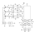
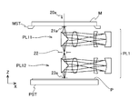
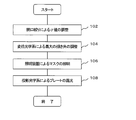
- FIG. 1 It is a perspective view which shows schematic structure of the exposure apparatus which concerns on one Embodiment. It is a figure which shows the structure of the illuminating device which concerns on one Embodiment. It is a figure which shows the structure of the partial projection optical system and stage system which concern on one Embodiment. It is a flowchart which shows an example of the illumination method and the exposure method.
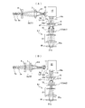
- A is a figure which shows the principal part of an illuminating device when (sigma) value of illumination light is large
- (B) is a figure which shows the principal part of an illuminating device when (sigma) value of illumination light is small.
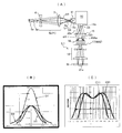
- FIG. (A) is a figure which shows the principal part of the illuminating device of a comparative example
- (B) is a figure which shows the light intensity distribution in the incident end of a light guide fiber
- (C) shows the light intensity distribution in the incident end of a fly eye lens.
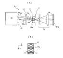
- FIG. (A) is a figure which shows a partial illumination optical system
- (B) is an enlarged view which shows the injection
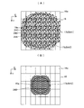
- (A) is a diagram illustrating an example of an aperture stop aperture during annular illumination
- (B) is a diagram illustrating an example aperture aperture aperture during large ⁇ illumination
- (C) is an aperture stop aperture during small ⁇ illumination. It is a figure which shows an example of opening.
- (A) And (B) is a conceptual diagram which shows the injection
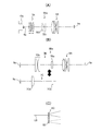
- (A) is a diagram showing a configuration example of a variable power optical system
- (B) is a diagram showing a configuration example of a switching optical system
- (C) is a diagram showing an example of an optical member that controls the tilt angle of a laser beam. It is. It is a flowchart which shows an example of the electronic device manufacturing method.
- FIG. 1 is a perspective view showing an exposure apparatus EX according to this embodiment.
- the exposure apparatus EX synchronously moves a mask M and a flat plate P as a substrate coated with a photosensitive agent with respect to a projection optical system PL having a plurality of catadioptric partial projection optical systems.
- the exposure apparatus employs a step-and-scan method for transferring an image of a pattern formed on the mask M to the plate P.
- the X axis and the Y axis are taken so as to be orthogonal to each other in a plane parallel to the plate P, and the Z axis is taken perpendicular to the plane (XY plane).
- the XY plane is set to a plane parallel to the horizontal plane
- the Z axis is set to be parallel to the vertical line.
- the scanning direction which is the direction in which the mask M and the plate P are moved synchronously, is set to a direction parallel to the X axis (X direction).
- the non-scanning direction orthogonal to the scanning direction is a direction parallel to the Y axis (Y direction).
- the exposure apparatus EX includes an illumination apparatus ILA for illuminating a pattern surface (hereinafter also referred to as a mask surface) of the mask M supported by the mask stage MST (see FIG. 3) with illumination light having a uniform illuminance distribution, and projection optics.
- a system PL and a control unit 30 including a computer for controlling the operation of the entire apparatus are provided.
- the illumination device ILA includes a plurality of (four in this case) illumination areas 21a, 21c, 21e, and 21g arranged in the Y direction (non-scanning direction) on the mask surface, and an illumination area in the first row.
- the illumination device ILA illuminates seven illumination areas on the mask surface, but the arrangement and number of illumination areas are arbitrary.
- the illumination regions 21a to 21g may have a shape slightly larger than the image on the mask surface of the field stop.
- the illuminating device ILA includes three light sources 2a, 2b, and 2c made of ultra high pressure mercury lamps.
- the illumination lights 3a, 3b, 3c emitted from the light sources 2a, 2b, 2c are condensed by elliptic mirrors 4a, 4b, 4c, respectively.
- the light sources 2a to 2c are arranged at the first focal positions of the elliptical mirrors 4a to 4c, and the light source images 5a, 5b, and 5c of the light sources 2a, 2b, and 2c are arranged at the second focal positions of the elliptical mirrors 4a, 4b, and 4c. Is formed.
- the illumination light 3a, 3b, 3c is shielded by a shutter (not shown) disposed near the second focal point of the elliptical mirrors 4a, 4b, 4c.
- the number of the light sources 2a, 2b, and 2c is arbitrary, and one light source (for example, only the light source 2a) may be sufficient.
- Illumination lights 3a, 3b, 3c emitted as divergent light from the light source images 5a, 5b, 5c are condensed on the incident ends 12a, 12b, 12c of the light guide fiber 10 by the variable magnification optical systems 8a, 8b, 8c, respectively.
- the variable magnification optical systems 8a, 8b, and 8c form images (hereinafter, referred to as light source images) 9a, 9b, and 9c with variable magnifications of the light source images 5a, 5b, and 5c on the incident surfaces of the incident ends 12a, 12b, and 12c, respectively. To do.
- the zoom optical systems 8a to 8c include a front group lens system 6 that can be moved along the optical axis by the drive unit 6a, and a rear group lens system 7 that can be moved along the optical axis by the drive unit 7a.
- This is a lens (zoom optical system).
- the control unit 30 can control the magnifications of the variable magnification optical systems 8a to 8c by controlling the positions of the front group lens system 6 and the rear group lens system 7 via the drive units 6a and 7a.
- the height (image height) of the light source image 9a when the variable magnification optical system 8a is at the minimum magnification is y1, and the maximum inclination angle with respect to the optical axis of the illumination light 3a forming the light source image 9a at this time is ⁇ 1.
- the height of the light source image 9a when the magnification of the variable magnification optical system 8a is a maximum magnification higher than the magnification is y2, and the maximum inclination angle with respect to the optical axis of the illumination light 3a at this time is ⁇ 2.
- the maximum inclination angle is also a half of the so-called cone angle.
- the height of the light source image 9a is, for example, about 10% to 50% of the maximum intensity of the light intensity distribution. It is also possible to regard the position as an interval, or an interval between positions where the position is approximately 30%, for example. Assuming that the variable magnification optical system 8a satisfies the sine condition, the following relationship is established.
- variable magnification optical systems 8a to 8c are optical systems that can control or adjust the maximum tilt angle of the illumination light incident on the incident ends 12a to 12c by forming light source images 9a to 9c with variable magnification. is there. In the present embodiment, the variable magnification optical systems 8a to 8c are controlled to have the same magnification.
- the light guide fiber 10 as an optical transmission member is a fiber bundle formed by randomly bundling a large number of optical fiber wires 11 (see FIG. 5A), and includes three incident ends 12a, 12b, and 12c. , And a plurality of (here, seven) emission ends (only the emission ends 14a and 14B are shown in FIG. 2) corresponding to a plurality (here, seven) illumination regions, and the incidence ends 12a to 12c.
- the illumination lights 3a to 3c received from are distributed to the plurality of exit ends. Accordingly, at least a part of each of the illumination lights 3a to 3c is emitted from the plurality of emission ends, and the illumination device ILA can emit the illumination lights emitted from the plurality of light sources 2a to 2c, respectively. it can.
- the light guide fiber 10 is configured to distribute and emit each illumination light received from the incident ends 12a to 12c to a plurality of emission ends with a substantially equal light amount ratio.
- the optical fiber 11 is emitted while maintaining the inclination angle of the incident light beam so that the maximum inclination angle of the incident light beam and the maximum inclination angle of the emitted light beam are substantially equal. It is. For this reason, the maximum inclination angle of the illumination lights 3a to 3c incident on the incident ends 12a to 12c of the light guide fiber 10 is substantially equal to the maximum inclination angle of the illumination light emitted from the plurality of emission ends.
- illumination light emitted from the variable magnification optical systems 8a to 8c is incident on the corresponding incident ends 12a to 12c in a state where the principal ray is parallel to the optical axis, that is, in a so-called telecentric state. .
- the illumination light can be uniformly incident within the range of the incident angle at which each optical fiber 11 of the light guide fiber 10 can be transmitted.
- the maximum tilt angle of the illumination light emitted from the variable magnification optical systems 8a to 8c is controlled in a range smaller than the maximum incident angle (tilt angle) that can be transmitted by the optical fiber 11.
- Each of the illumination lights 20a, 20c, etc. emitted from the plurality of exit ends 14a, 14b, etc. of the light guide fiber 10 illuminates the partial illumination areas 21a, 21c, etc. of the mask M (seven here).
- the light beams are incident on partial illumination optical systems IL1 to IL7 having the same configuration (however, partial illumination optical systems IL2 and IL4 to IL7 are not shown).
- the partial illumination optical systems IL1 to IL7 are respectively associated with partial projection optical systems PL1 to PL7 described later, and are arranged in a staggered pattern along the non-scanning direction (Y direction) orthogonal to the scanning direction.
- the illumination light 20a. 20c is condensed by the input lens 15 that is a collimating lens and converted into a parallel light beam, and then enters the fly-eye lens 16 that is an optical integrator.
- the illumination lights 20a and 20c incident on the fly-eye lens 16 are wavefront-divided by a number of lens elements constituting the fly-eye lens 16, and a plurality of illumination lights 20a and 20c are formed on the rear focal plane in the vicinity of the exit plane (exit pupil plane of the illumination optical system).
- a secondary light source (surface light source) is formed from the light source images.
- An aperture stop 17 is disposed on the rear focal plane.
- the control unit 30 controls the size and shape of the aperture of the aperture stop 17 via the drive unit 17a.
- the numerical aperture NA of the illumination light that illuminates the mask M by the partial illumination optical systems IL1 and IL3 can be controlled.
- the numerical aperture NA of illumination light is expressed using a ⁇ value that is a coherence factor (a value obtained by dividing the numerical aperture of illumination light that illuminates the mask by the numerical aperture on the mask side of the projection optical system).
- the aperture stop 17 can also be called a ⁇ stop.
- the aperture stop 17 may be replaced with an annular illumination aperture stop (not shown) having an annular-shaped variable aperture.
- the illumination lights 20a and 20c emitted from the aperture of the aperture stop 17 illuminate the corresponding illumination areas 21a and 21c on the mask M with a substantially uniform illuminance distribution via the condenser lens 18.
- the configuration of the partial illumination optical systems IL2, IL4 to IL7 (not shown) is the same as that of the partial illumination optical system IL1, and each of the partial illumination optical systems IL2, IL4 to IL7 on the mask M is similar to the partial illumination optical system IL1.
- the corresponding illumination area is illuminated with a substantially uniform illumination distribution.
- FIG. 3 is a diagram showing a configuration of the partial projection optical system PL1.
- the partial projection optical system PL ⁇ b> 1 includes a first catadioptric optical system PL ⁇ b> 11 that forms an intermediate image of a pattern provided in the corresponding illumination area 21 a on the mask surface at the opening of the field stop 22.
- the second catadioptric optical system forms an image of the pattern of the mask M as an equal-magnification erect image on the exposure region 23a of the plate P supported by the plate stage PST.
- the partial projection optical systems PL2 to PL7 have the same configuration as the partial projection optical system PL1, and form an image of the pattern formed in the corresponding illumination area on the mask surface on the plate P. .
- the partial projection optical systems PL1 to PL7 are arranged in a staggered pattern along the non-scanning direction.
- a power supply device 32 that supplies power to the light sources 2a to 2c is connected to the control unit 30.
- the control unit 30 turns on the light sources 2a to 2c via the power supply device 32 when performing exposure of the plate P or calibration of the illumination device ILA.
- the required exposure amount is small, it is possible to turn on only at least one of the light sources 2a to 2c.
- the control unit 30 sets illumination conditions including the ⁇ value of illumination light and the magnification of the variable magnification optical systems 8a to 8c (details will be described later), and turns on the light sources 2a to 2c.
- the mask M is illuminated by the illumination device ILA
- the mask stage MST that supports the mask M and the plate stage PST that supports the plate P are driven, and the mask M and the plate P are moved to the partial projection optical systems PL1 to PL7.
- the pattern formed on the mask M by the step-and-scan method by repeating the movement in the scanning direction (scanning exposure) and the movement of the plate P in the non-scanning direction or the scanning direction (step movement). Are exposed to a plurality of exposed areas of the plate P.
- illuminance sensors (not shown) are arranged at a plurality of positions in the illumination areas 21a to 21g. Then, when the light sources 2a to 2c are turned on to change the ⁇ value and the magnification of the variable magnification optical systems 8a to 8c is changed, the illuminance distribution measured by the illuminance sensor is a target. By adjusting the variable magnification optical systems 8a to 8c and the partial illumination optical systems IL1 to IL7 so as to be within a predetermined allowable range with respect to the distribution, the illuminance distribution becomes uniform.
- the operation is controlled by the control unit 30.
- the partial illumination optical systems IL1 to IL7 of the illumination device ILA are changed according to the pattern type and fineness of the mask M to be exposed.
- the aperture stop 17 the ⁇ value of the illumination light is controlled.
- the aperture stop 17 may be replaced with an aperture stop (not shown) for annular illumination.
- the diameter of the circular aperture of the aperture stop 17 is set to the maximum value, and the ⁇ value is set to the maximum value NA1 (for example, about 0.8 to 0.9).
- NA1 for example, about 0.8 to 0.9.
- a large ⁇ illumination is assumed.
- the illumination light emitted from the exit end 14a of the light guide fiber 10 becomes a parallel light beam via the input lens 15 and has the widest range of the entrance surface of the fly-eye lens 16 (aperture stop 17). A range slightly wider than the area facing the largest aperture of the light source). For this reason, it is necessary to set the maximum inclination angle of the illumination light emitted from the emission end 14a to a maximum value within an adjustable range.
- step 104 the magnifications of the variable magnification optical systems 8a to 8c and, consequently, the light source images 9a to 9c formed on the incident ends 12a to 12c of the light guide fiber 10 according to the ⁇ value set by the aperture stop 17 are obtained.
- the maximum inclination angle of the illumination lights 3a to 3c to be formed is adjusted.
- a ⁇ value determined by the outer diameter of the annular aperture may be used as the ⁇ value.
- NA1 the magnification of the variable magnification optical systems 8a to 8c is set to the minimum value within the variable range, and the maximum inclination angle of the illumination lights 3a to 3c is adjusted.
- the maximum value ⁇ 1 is set within a possible range.
- the focal length of the variable magnification optical system 8a is set to f1
- the height of the light source image 9a is set to the minimum value y1 within the adjustable range.
- the maximum inclination angle of the incident light beam and the maximum inclination angle of the outgoing light beam are substantially equal. For this reason, when the aperture diameter of the aperture stop 17 is maximized, the illumination light 20a emitted from the exit end 14a of the light guide fiber 10 is able to illuminate the maximum aperture via the input lens 15. Is incident on the area of the incident surface.
- the light intensity distribution (illuminance distribution) D1 of the light source image 9a formed at the incident end 12a has a substantially axially symmetric normal distribution shape, with a strong central portion and a sharp decrease toward the peripheral portion.
- the light intensity distribution D1 has a portion of about 10% or less with respect to the maximum value spreading outside the incident surface of the incident end 12a.
- a portion (more precisely, a light beam obtained by randomly combining incident illumination lights 3a to 3c) is emitted from the exit end 14a or the like.
- the light intensity distribution C31 of the illumination light 20a emitted from the exit end 14a on the entrance surface of the fly-eye lens 16 is a substantially axisymmetric distribution that becomes slightly stronger as it goes away from the optical axis and rapidly decreases outside the optical axis.
- the light intensity distribution C31 can be regarded as a substantially uniform value in a region facing the aperture of the aperture stop 17, and illumination with a maximum inclination angle of approximately ⁇ 1 is emitted from the exit end 14a to the aperture of the aperture stop 17. Most of the light 20a is incident.
- the utilization efficiency of the illumination light (hereinafter referred to as the ratio of the illumination light 20a incident on the mask M through the condenser lens 18 through the aperture of the aperture stop 17 to the illumination light 3a incident on the light guide fiber 10) (Also called lighting efficiency) is high.
- step 106 the light sources 2a to 2c are turned on, and the illuminating device ILA emits the light beams 3a to 3c from the light sources 2a to 2c to change the magnification optical systems 8a to 8c, the light guide fiber 10, the partial illumination optical systems IL1 to
- the mask M is illuminated via the input lens 15 of IL8, the fly-eye lens 16, the aperture stop 17, and the condenser lens 18.
- step 108 the plate P is exposed by synchronously moving the mask M and the plate P with respect to the projection optical system PL while exposing the plate P with the pattern image of the mask M by the projection optical system PL. .
- the mask M can be illuminated with high illumination efficiency using the illumination light having the maximum ⁇ value, the pattern formed on the mask M can be exposed to the plate P with high throughput (productivity) with high light accuracy.
- the diameter of the circular aperture of the aperture stop 17 is set to a minimum value, and the ⁇ value is set to a minimum value NA2 (for example, about 0.05 to 0.1).
- NA2 for example, about 0.05 to 0.1.
- the illumination light emitted from the exit end 14a becomes a parallel light beam via the input lens 15, and is the smallest area on the entrance surface of the fly-eye lens 16 (more than the area facing the smallest opening of the aperture stop 17).
- the maximum inclination angle of the illumination light emitted from the emission end 14a may be set to the minimum value ⁇ 2 within the adjustable range. Therefore, in step 104, the magnification of the variable magnification optical systems 8a to 8c is set to the maximum value within the range where the magnification can be changed, and the maximum inclination angle of the illumination lights 3a to 3c is set to the minimum value ⁇ 2.
- the focal length of the variable magnification optical system 8a is set to f2
- the height of the light source image 9a is set to the maximum value y2.
- the light intensity distribution D2 of the light source image 9a formed at the incident end 12a is a substantially axially symmetric normal distribution obtained by enlarging the light intensity distribution D1 of FIG. 5A with the magnification ratio y2 / y1.
- a portion of about 35% or less with respect to the maximum value spreads outside the incident surface of the incident end 12a, and about 60% of the incident illumination lights 3a to 3c, for example, the emission end 14a and the like. Is injected from.
- the height y2 of the light source image 9a is the interval of the portion where the light intensity is approximately 30% of the maximum value
- the light source image 9a having the height y2 is slightly larger than the width of the incident end 12a.
- the maximum inclination angle of the illumination light 20a emitted from the emission end 14a is almost the minimum value ⁇ 2, and most of the illumination light 20a is incident on the fly-eye lens 16 via the input lens 15. In the surface, the light enters the region facing the smallest aperture of the aperture stop 17.
- the light intensity distribution C11 of the illumination light 20a emitted from the emission end 14a on the incident surface of the fly-eye lens 16 is substantially axially symmetric as if the light intensity distribution C31 in FIG. Distribution.
- the light intensity distribution C11 can be regarded as a substantially uniform value in a region facing the smallest aperture of the aperture stop 17, and the aperture of the aperture stop 17 is emitted from the exit end 14a with a maximum inclination angle of approximately ⁇ 2. Most of the illumination light 20a is incident. For this reason, even if a certain amount of light loss of the illumination light 3a incident on the incident end 12a occurs to some extent, the illumination light 3a of the illumination light 20a that passes through the minimum aperture of the aperture stop 17 and enters the mask M via the condenser lens 18 The utilization efficiency for is increasing. Thereafter, by performing Steps 106 and 108, for example, a pattern including an isolated pattern can be exposed on the plate P with high throughput and high accuracy.
- the magnification of the variable magnification optical system 8a is set to the minimum as in the case of FIG. 5A (the maximum inclination angle of the illumination light 3a is maximized).
- the ⁇ value is set to the minimum value NA2 at the aperture stop 17 (set to the value ⁇ 1).
- the light intensity distribution C31 of the illumination light 20a emitted from the exit end 14a on the entrance surface of the fly-eye lens 16 is considerably large even in the region 16Aa outside the region facing the smallest aperture of the aperture stop 17. It is getting stronger. For this reason, about 45% of the illumination light 20a emitted from the emission end 14a can pass through the opening of the aperture stop 17 for example.
- the three light sources 2a to 2c are used.
- the illumination efficiency is improved by 30%, for example, it is possible to perform the exposure by lighting only the two light sources 2a and 2b. Therefore, the lifetime of the light sources 2a to 2c can be extended.
- FIG. 6B shows the light intensity distributions D1 and D2 of the illumination light 3a at the incident end 12a in FIGS. 5A and 5B in terms of relative light intensity.
- the abscissa represents the distance from the center as a relative value with the center position of the incident end 12a being zero.
- the position where the value of the horizontal axis is 50 is, for example, the position of the edge portion of the incident end 12a.
- the light intensity distribution D3 in FIG. 6B shows the light amount of the illumination light that has passed through the aperture of the aperture stop 17 and the illumination light that is incident on the fly-eye lens 16 in the case of the comparative example in FIG. This is a distribution obtained by compressing the light intensity distribution D1 by the ratio.
- the amount of light obtained by integrating the light intensity distribution D2 inside the position ⁇ 50 is the amount of light obtained in this embodiment, and the amount of light obtained by integrating the light intensity distribution D3 is the amount of light obtained in the comparative example. From the results, it can be seen that the illumination efficiency is improved by this embodiment.
- FIG. 6C shows the light intensity distributions C31 and C11 of the illumination light 20a on the incident surface of the fly-eye lens 16 shown in FIGS. 5A and 5B in terms of relative light intensity.
- the horizontal axis of 6 (C) represents the distance from the center as a ⁇ value with the center position of the incident surface being zero.
- the relative intensities of the light intensity distributions C31 and C11 are adjusted so that the ⁇ values are equal to 0.88 and 0.65. In this case, if the values of the light intensity distributions C31 and C11 at the position where the ⁇ value is 0.5 are the average light intensity or the average illuminance, the average illuminances of the light intensity distributions C31 and C11 are almost equal.
- step 102 when the ⁇ value is set to an arbitrary value NA3 between the maximum value NA1 and the minimum value NA2 using the aperture stop 17, in step 104, the variable magnification optical systems 8a to 8c are set.
- the magnification may be set to a value ⁇ 3 between the minimum value (referred to as ⁇ 1) in the case of FIG. 5A and the maximum value (referred to as ⁇ 2) in the case of FIG.
- ⁇ 3 is gradually set larger as the ⁇ value NA3 is gradually reduced as represented by the following equation, and the maximum inclination angle of the illumination light incident on the light guide fiber 10 is gradually reduced. .
- ⁇ 3 ⁇ 1 + (NA1-NA3) ( ⁇ 2- ⁇ 1) / (NA1-NA2) (2)
- the mask M can be illuminated with high illumination efficiency in accordance with the ⁇ value (illumination condition) regardless of the ⁇ value, and the pattern of the mask M can be applied to the plate P with high throughput and high accuracy. Can be exposed.
- FIG. 7A is an enlarged view showing the partial illumination optical system IL1 of FIG. 5A
- FIG. 7B is an enlarged view of the exit end 14a of the light guide fiber 10 of FIG. 7A viewed from the front.
- FIG. 7A a part of the lens elements 16a having the same shape and constituting the fly-eye lens 16 are shown enlarged.
- the exit end 14a is configured by regularly bundling a large number of optical fiber strands 11.
- the exit end 14a is imaged by the input lens 15 and the lens element 16a on the exit surface of the lens element 16a (a so-called pupil plane on which the aperture stop 17 is disposed).
- the illumination area 21a is an exposure field (an area conjugate with the aperture of the field stop 22 in FIG. 3).
- the shape of each lens element 16a of the fly-eye lens 16 is determined so as to be slightly larger than ().
- the light intensity distribution at the incident end 12a of the light guide fiber 10 is changed by the variable magnification optical system 8a.
- the light emitted from the optical fiber 11 on which light having a light intensity of up to about 10% of the maximum light intensity at the time of large ⁇ illumination enters is transmitted through the input lens 15 and the fly-eye lens 16.
- the light source image formed on the arrangement surface of the aperture stop 17 is regarded as an effective light source image contributing to illumination.
- light emitted from all the optical fiber strands 11 at the exit end 14a forms an effective light source image, it is formed on the exit surface of the lens element 16a of the fly-eye lens 16 in the range where the light enters.
- the number n1 of effective light source images to be performed is the same as the number n2 of the optical fiber strands 11 constituting the emission end 14a.
- This is referred to as a filling factor ⁇ of illumination light from the optical fiber 11.
- the magnification of the variable magnification optical system 8a (the maximum inclination angle of illumination light incident on the incident end 12a) is adjusted so that the filling factor ⁇ is maintained at 1 (100%).
- annular illumination, large ⁇ illumination, or small ⁇ illumination the exit surface of the lens element 16a of the fly-eye lens 16 in the aperture stop 17 is shown in FIG.
- an effective light source image 24 is formed with the same maximum density distribution (a distribution corresponding to the density distribution of the optical fiber 11 in FIG. 7B). Is done.
- the aperture of the aperture stop 17 is set as a ring-shaped aperture 17c.
- the maximum inclination angle of illumination light incident on the incident ends 12a to 12c of the light guide fiber 10 from the variable magnification optical systems 8a to 8c is larger than that when small ⁇ illumination is performed. It is set large.
- each lens element 16a of the fly-eye lens 16 is actually closer to the openings 17b and 17c. Is also greatly represented.
- the illumination light filling rate ⁇ from the optical fiber 11 in the case of performing annular illumination, large ⁇ illumination, or small ⁇ illumination is within a range where the common ratio is 1, and the variable power optical The magnification of the system 8a is adjusted.
- the filling rate ⁇ may be approximately 1 (for example, 0.9 to 1).
- the light intensity of the illumination light incident on the incident ends 12a to 12c of the light guide fiber 10 is maximum at the central portion, and decreases toward the periphery. Therefore, among the many optical fiber strands 11 constituting the incident end 12a, for example, light intensity of about 70% or more, 70 to 40%, and 40 to 10% with respect to the maximum value at the time of large ⁇ illumination.
- the light source images formed by the illumination light from the optical fiber 11 on which the illumination light 3a enters are referred to as light source images 24A, 24B, and 24C, respectively. At this time, as shown in FIG.
- the exit surface of the fly-eye lens 16 on the exit surface of the lens element 16a in the aperture 17b of the aperture stop 17 is not shown.
- the light source images 24A, 24B, and 24C are formed in a random arrangement.
- the illumination light emitted from the exit end 14a of the light guide fiber 10 is incident on the plurality of lens elements 16a (optical elements) of the fly-eye lens 16 (at portions of the plurality of lens elements 16a in the large opening 17b). It is distributed over a wider area than the size of the incident surface.
- the exit surface of the fly-eye lens 16 has an exit surface of the lens element 16a in the aperture 17b of the aperture stop 17.
- light source images 24B having a substantially medium light intensity are formed in a regular arrangement.
- the illumination light emitted from the exit end 14a of the light guide fiber 10 is distributed in a region wider than the size of the entrance of the plurality of lens elements 16a of the fly-eye lens 16 in the portion of the small opening 17b. .
- the light intensity of the light source image 24B formed on the exit surface of each lens element 16a of the fly-eye lens 16 is more uniform than in the case of FIG. Will be.
- the illuminating device ILA that illuminates the mask M of the present embodiment includes the light source 2a that generates the illumination light, the variable magnification optical system 8a that adjusts the maximum inclination angle of the illumination light in Step 104, and Step 106.
- the input lens 15 (hereinafter also referred to as a first condensing optical system) for condensing the illumination light via the variable magnification optical system 8a into a parallel light beam, and in step 106, illumination via the variable magnification optical system 8a.
- a light guide fiber 10 (hereinafter also referred to as an optical member) that emits light to the input lens 15 while maintaining the maximum inclination angle of the illumination light, and in step 102, the numerical aperture ( ⁇ value) of the illumination light is set.
- An aperture stop 17 to be adjusted, and a condenser lens 18 (hereinafter also referred to as a second condensing optical system) for guiding the illumination light whose numerical aperture is controlled in Step 106 to the mask M. It is provided.
- the aperture stop 17 is reduced by reducing the maximum inclination angle of the illumination light by the variable magnification optical system 8a.
- the ratio of the illumination light incident on the aperture of the light can be increased, and the utilization efficiency of the illumination light can be increased.
- the mask M can be illuminated with higher illuminance.
- the life of the light source 2a can be extended, and when a plurality of light sources 2a to 2c are used, the number of light sources to be used can be reduced and the illumination device ILA can be reduced in size. Cost reduction can be achieved.
- the light guide fiber 10 since the light guide fiber 10 is used, the light source 2a and the mask M can be separated, and the thermal expansion of the mask M can be suppressed.
- the exposure apparatus EX that exposes the pattern of the mask M of the present embodiment onto the plate P includes an illumination apparatus ILA that illuminates the mask M in steps 102 to 106, and a mask M that is illuminated by the illumination apparatus ILA in step 108.
- a projection optical system PL that forms an image of the pattern on the plate P.
- the light guide fiber 10 includes a plurality of incident ends 12a to 12c and a plurality of exit ends 14a and 14b, etc.
- the illumination light from the plurality of light sources 2a to 2c is randomly mixed to produce a plurality of partial illuminations. It can be easily branched into light beams for the optical systems IL1 to IL7.
- the fly-eye lens 16 including the plurality of lens elements 16a is provided, the illuminance distribution of the illumination light in the illumination area of the mask M can be made more uniform.
- variable magnification optical system 8a of the above-described embodiment includes a front group lens system 6A composed of three lenses and a rear group lens system 7A composed of three lenses.
- a variable power optical system 8Aa that adjusts the position of the rear lens group system 7A can be used.
- variable magnification optical system 8a an optical system of a type that forms an intermediate image of the light source image on the optical path between the light source image 5a and the light source image 9a can be used.
- the variable magnification optical system 8a is used to control the maximum tilt angle of the illumination light.
- a relay optical system 8Ba that switches the magnification by partially replacing the optical system may be used.
- the relay optical system 8Ba includes a front group lens system 6A, a first rear group lens system 7B composed of a lens group 7Bb having a lens 7Ba and two lenses, and a second rear group lens system composed of lenses 7Ca and 7Cb.
- the light source image 9a is formed using the front group lens system 6A and the first rear group lens system 7B.
- the first rear group lens system 7B is used instead of the first rear group lens system 7B.
- a light source image 9a is formed by using the second rear group lens system 7C. In this way, when the replaceable relay optical system 8Ba is used, an optical system for controlling the tilt angle can be manufactured at low cost.
- an optical system composed of two conical prism-shaped optical members 7B1 and 7B2 may be provided.
- the two optical members 7B1 and 7B2 are brought into close contact with each other, and when performing annular illumination, the distance between the two optical members 7B1 and 7B2 is adjusted, and the front group
- the cross-sectional shape of the illumination light 3a passing between the lens system 6 and the rear group lens system 7 may be a ring-shaped shape having a variable size.
- the illumination light 20 a emitted from the emission end 14 a of the light guide fiber 10 enters the ring-shaped region on the incident surface of the fly-eye lens 16 via the input lens 15.
- use of illumination light when performing annular illumination is performed by adjusting the distance between the two optical members 7B1 and 7B2 according to the size of the annular aperture of the aperture stop. Efficiency can be further improved.
- the fly-eye lens 16 is used as the optical integrator.
- a micro-lens array, a rod integrator, or the like may be used instead of the fly-eye lens 16.
- ultra high pressure mercury lamps are used as the light sources 2a to 2c, but lamps such as other arbitrary discharge lamps can be used as the light sources 2a to 2c.
- a light emitting diode (LED) or the like can be used as the light sources 2a to 2c.
- laser light sources such as solid lasers, gas lasers, or semiconductor lasers may be used. It is also possible to use harmonics of laser light as illumination light.
- a laser light source is used as the light source and the maximum tilt angle of the illumination light is set large, as an example, as shown in FIG. 10C, parallel light beams generated from a laser light source (not shown)
- a diffraction grating 8C On the optical path of the laser beam LB, a diffraction grating 8C on which concentric (zone plate-like) phase-type irregularities with a finer pitch is formed is disposed.
- the minimum pitch of the diffraction grating 8C is defined according to the maximum tilt angle.
- a diffraction grating 8D having a minimum pitch larger than the diffraction grating 8C is disposed.
- illumination light with a maximum maximum tilt angle can be generated
- illumination light with a maximum maximum tilt angle can be generated.
- the multi-lens scanning exposure apparatus has been described as an example.
- the pattern of the mask M is exposed while the mask M and the plate P are stationary.
- the above-described embodiment can also be applied to a step-and-repeat type exposure apparatus that sequentially moves the plate P stepwise.
- the illuminating device may be provided with one, two, or four or more light sources.
- the light guide fiber has seven exit ends. However, the number of exit ends of the light guide fiber is not limited as long as it is one or more.
- the illumination light from the plurality of light sources 2a to 2c is branched into the light beams for the plurality of partial illumination optical systems IL1 to IL7.
- the mask M may be illuminated via the illumination optical system IL1, and the pattern of the mask M may be transferred to the plate P via one imaging optical system (for example, an optical system similar to the partial projection optical system PL1).
- the illumination light 3 a from the variable magnification optical system 8 a may be directly incident on the fly-eye lens 16 via the input lens 15 without providing the light guide fiber 10.
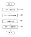
- FIG. 11 is a flowchart showing a manufacturing process of a liquid crystal device such as a liquid crystal display element.
- a pattern formation process step 200
- a color filter formation process step 202
- a cell assembly process step 204
- a module assembly process step 206
- a predetermined pattern such as a circuit pattern and an electrode pattern is formed on a glass substrate coated with a photoresist as a plate using the above-described exposure apparatus or exposure method.
- an exposure process in which the pattern is transferred to the photoresist layer using the exposure apparatus or exposure method of the above-described embodiment, and development of the plate to which the pattern has been transferred, and a photo of the shape corresponding to the pattern is performed.
- a development step for generating the resist layer as a mask layer and a processing step for processing the surface of the glass substrate through the developed photoresist layer are included.
- a large number of sets of three dots corresponding to R (red), G (green), and B (blue) are arranged in a matrix, or three of R, G, and B are arranged.
- a color filter is formed by arranging a plurality of stripe filter sets in the horizontal scanning direction.
- a liquid crystal panel liquid crystal cell
- a liquid crystal panel is formed by injecting liquid crystal between a glass substrate and a color filter.
- step 206 various components such as an electric circuit and a backlight for performing the display operation of the liquid crystal panel are attached to the liquid crystal panel assembled in step 204.
- a predetermined pattern is formed on the glass substrate using the exposure apparatus EX or the exposure method of the above-described embodiment, and the glass substrate is inserted through the predetermined pattern. And processing.
- the exposure apparatus EX or the exposure method of this embodiment since exposure can be performed with high illumination efficiency, an electronic device can be manufactured with high throughput and high accuracy.
- the exposure apparatus EX or the exposure method of the above-described embodiment can also be applied when manufacturing a semiconductor device.
- the above-described embodiment is not limited to application to an exposure apparatus for manufacturing a semiconductor device or a liquid crystal device.
- an exposure apparatus for a display device such as a plasma display or an imaging element (CCD or the like)
- the present invention can also be widely applied to exposure apparatuses for manufacturing various devices such as micromachines, thin film magnetic heads, and DNA chips.
- the above-described embodiment can also be applied to an exposure apparatus for manufacturing a mask (photomask, reticle, etc.) used for manufacturing various devices using a photolithography process.
Landscapes
- Physics & Mathematics (AREA)
- General Physics & Mathematics (AREA)
- Optics & Photonics (AREA)
- Exposure And Positioning Against Photoresist Photosensitive Materials (AREA)
- Microscoopes, Condenser (AREA)
Abstract
Description
従来の照明装置として、水銀ランプからの照明光束の断面形状を制御するための複数の円錐又は角錐状の光学部材からなる光学系を備え、輪帯照明を行う場合に照明光の利用効率を高めるために、輪帯状の照明光源の形状に応じて、その光学系を用いて照明光束の断面形状を制御する照明装置が使用されている(例えば特許文献1参照)。
第3の態様によれば、マスクを照明する照明方法であって、光源から発生された照明光の傾き角を調整することと、その傾き角が調整されたその照明光を、その照明光のその傾き角を維持する光学部材を介して射出することと、射出されたその照明光を集光することと、その照明光の開口数を調整することと、開口数が調整されたその照明光をそのマスクに導くことと、を含む照明方法が提供される。
ここでは高さy2が高さy1より高いため、式(1)より、傾き角α2は傾き角α1よりも小さくなる。このことから、変倍光学系8a~8cは、倍率可変の光源像9a~9cを形成することによって、入射端12a~12cに入射する照明光の最大の傾き角を制御又は調整できる光学系でもある。本実施形態では、変倍光学系8a~8cは互いに同じ倍率になるように制御される。
まず、光源2a~2cを点灯させていない状態で、図4のステップ102において、露光対象のマスクMのパターンの種類及び微細度等に応じて、照明装置ILAの部分照明光学系IL1~IL7の開口絞り17を用いて、照明光のσ値を制御する。なお、輪帯照明を行う場合には、開口絞り17を輪帯照明用の開口絞り(不図示)と交換してもよい。ここでは、図5(A)に示すように、開口絞り17の例えば円形の開口の直径を最大値にして、σ値を最大値NA1(例えば0.8~0.9程度)に設定し、大σ照明を行うものとする。大σ照明を行う場合には、ライトガイドファイバ10の射出端14aから射出される照明光がインプットレンズ15を介して平行光束となってフライアイレンズ16の入射面の最も広い範囲(開口絞り17の最大の開口に対向する領域よりもわずかに広い範囲)を照明する必要がある。このため、射出端14aから射出される照明光の最大の傾き角を調整可能な範囲内の最大値に設定する必要がある。
これによって、どのようなσ値で照明を行う場合でも、σ値(照明条件)に応じて高い照明効率でマスクMを照明することができ、マスクMのパターンを高いスループットで高精度にプレートPに露光できる。
このとき、輪帯照明、大σ照明、又は小σ照明を行う場合に、開口絞り17の開口内にあるフライアイレンズ16のレンズエレメント16aの射出面には、それぞれ図8(A)、図8(B)、又は図8(C)に示すように、互いに同じ最大の密度分布(図7(B)の光ファイバ素線11の密度分布に対応する分布)で有効な光源像24が形成される。なお、図8(A)では、開口絞り17の開口が輪帯状の開口17cに設定されている。輪帯照明又は大σ照明を行う場合、変倍光学系8a~8cからライトガイドファイバ10の入射端12a~12cに入射する照明光の最大の傾き角は、小σ照明を行う場合に比べて大きく設定される。
このように、本実施形態では、輪帯照明、大σ照明、又は小σ照明を行う場合の光ファイバ素線11からの照明光の充填率γは共通に1となる範囲で、変倍光学系8aの倍率が調整されている。この場合、開口絞り17の開口内の有効な光源像14の数が最大であるため、マスクMにおける照度分布の均一性が良好である。なお、充填率γはほぼ1(例えば0.9~1)でもよい。
これに対して、図5(B)に示すように、σ値を小さく設定する場合には、フライアイレンズ16の射出面において、開口絞り17の開口17b内のレンズエレメント16aの射出面には、図9(B)に示すように、ほぼ中程度の光強度の光源像24Bが規則的な配置で形成される。また、ライトガイドファイバ10の射出端14aから射出される照明光は、小さい開口17b内にある部分のフライアイレンズ16の複数のレンズエレメント16aの入射口の大きさよりも広い領域に分布している。このため、小σ照明ではフライアイレンズ16の各レンズエレメント16aの射出面に形成される光源像24Bの光強度が図9(A)の場合より均一であるため、照度分布がより均一化されることになる。
また、複数のレンズエレメント16aを含むフライアイレンズ16を備えているため、マスクMの照明領域における照明光の照度分布をより均一にできる。
上述の実施形態の変倍光学系8aとしては、図10(A)に示すように、3枚のレンズよりなる前群レンズ系6Aと、3枚のレンズよりなる後群レンズ系7Aとを有し、倍率調整時には、例えば後群レンズ系7Aの位置を調整する変倍光学系8Aaを使用することができる。
また、上述の実施形態では、照明光の最大の傾き角を制御するために変倍光学系8aが使用されているが、変倍光学系8aの代わりに、図10(B)に示すように、光学系を部分的に交換して倍率を切り換える方式のリレー光学系8Baを使用してもよい。リレー光学系8Baは、前群レンズ系6Aと、レンズ7Ba及び2枚のレンズを有するレンズ群7Bbよりなる第1の後群レンズ系7Bと、レンズ7Ca及び7Cbよりなる第2の後群レンズ系7Cとを有する。そして、倍率が低いときには、前群レンズ系6Aと第1の後群レンズ系7Bとを用いて、光源像9aを形成し、倍率が高いときには、第1の後群レンズ系7Bの代わりに第2の後群レンズ系7Cを用いて光源像9aを形成する。このように交換式のリレー光学系8Baを使用する場合には、傾き角を制御するための光学系を安価に製造できる。
上述の実施形態では、光源2a~2cとして超高圧水銀ランプが使用されているが、光源2a~2cとしては、他の任意の放電ランプ等のランプを使用できる。また、光源2a~2cとして、発光ダイオード(LED)等を使用することも可能である。また、光源2a~2cとして、固体レーザ、気体レーザ、又は半導体レーザ等のレーザ光源を使用してもよい。また、照明光としてレーザ光の高調波等を使用することも可能である。
ステップ204のセル組立工程では、ステップ200によって所定パターンが形成されたガラス基板と、ステップ202によって形成されたカラーフィルタとを用いて液晶パネル(液晶セル)を組み立てる。具体的には、例えばガラス基板とカラーフィルタとの間に液晶を注入することで液晶パネルを形成する。
Claims (29)
- マスクを照明する照明装置であって、
照明光を発生する光源と、
前記照明光の傾き角を調整する光学系と、
前記光学系を介した前記照明光を集光する第1集光光学系と、
前記光学系を介した前記照明光を、前記照明光の前記傾き角を維持して前記第1集光光学系に射出する光学部材と、
前記第1集光光学系から射出した前記照明光の開口数を調整する開口絞りと、
開口数が調整された前記照明光を前記マスクに導く第2集光光学系と、
を備える照明装置。 - 前記第1集光光学系は、前記照明光の照度分布を均一化する複数の光学要素を含んだ光学要素群を有し、
前記光学部材を通過した前記照明光は、前記第1集光光学系の複数の前記光学要素の入射口の大きさよりも広い領域に分布する、請求項1に記載の照明装置。 - 前記開口絞りの開口数に基づいて、前記光学系は、前記照明光の前記傾き角を調整する、請求項1又は2に記載の照明装置。
- 前記開口絞りで開口数を小さくするときに、前記光学系は、前記照明光の前記傾き角を小さくする、請求項3に記載の照明装置。
- 前記開口絞りで開口数を大きくするか、又は前記開口絞りの開口を輪帯形状にするときに、前記光学系は、前記照明光の前記傾き角を大きくする、請求項3に記載の照明装置。
- 前記光学系は、前記光源の倍率可変の像を形成する変倍光学系である、請求項1~5のいずれか一項に記載の照明装置。
- 前記開口絞りで開口数を小さくするときに、前記変倍光学系は、前記光源の像の倍率を大きくする、請求項6に記載の照明装置。
- 前記開口絞りで開口数を大きくするか、又は前記開口絞りの開口を輪帯形状にするときに、前記変倍光学系は、前記光源の像の倍率を小さくする、請求項6に記載の照明装置。
- 前記光学部材は、前記光学系を介した前記照明光を、前記照明光の前記傾き角を維持して複数の光束に分岐し、
前記第1集光光学系、前記開口絞り、及び前記第2集光光学系を、前記光学部材で分岐される前記複数の光束に対応して複数組備え、
前記マスクの複数の照明領域を照明する、請求項1~8のいずれか一項に記載の照明装置。 - 前記光学部材は、複数の入射端を有し、
前記光源及び前記光学系を、前記光学部材の前記複数の入射端に対応して複数組備える、請求項9に記載の照明装置。 - 前記光源の像の照度分布は正規分布状である、請求項1~10のいずれか一項に記載の照明装置。
- 前記光学部材は複数の光ファイバ素線を束ねて構成され、
前記光学部材の射出端を構成する前記光ファイバ素線の数と、前記光学要素群の複数の前記光学要素のそれぞれの射出端に形成される光源像の数とがほぼ等しい範囲で、前記開口絞りで前記照明光の開口数を調整する、請求項2に記載の照明装置。 - マスクのパターンを基板に露光する露光装置であって、
請求項1~12のいずれか一項に記載の照明装置と、
前記照明装置で照明された前記マスクのパターンの像を基板に形成する投影光学系と、を備える露光装置。 - 前記照明装置は前記マスクの複数の照明領域を照明し、
前記投影光学系を、前記複数の照明領域に対応して複数備え、
前記複数の照明領域の配列方向に交差する方向に、前記マスクと前記基板とを相対的に走査するステージ装置を備える請求項13に記載の露光装置。 - マスクを照明する照明方法であって、
光源から発生された照明光の傾き角を調整することと、
前記傾き角が調整された前記照明光を、前記照明光の前記傾き角を維持する光学部材を介して射出することと、
射出された前記照明光を集光することと、
前記照明光の開口数を調整することと、
開口数が調整された前記照明光を前記マスクに導くことと、
を含む照明方法。 - 前記照明光を集光することは、複数の光学要素を含んだ光学要素群を用いて前記照明光の照度分布を均一化することを含み、
前記光学部材を通過した前記照明光は、複数の前記光学要素の入射口の大きさよりも広い領域に分布する、請求項15に記載の照明方法。 - 前記照明光の前記傾き角を調整することは、前記照明光の開口数に基づいて前記照明光の前記傾き角を調整することを含む、請求項15又は16に記載の照明方法。
- 前記照明光の開口数を小さくするときに、前記照明光の前記傾き角を小さくする、請求項17に記載の照明方法。
- 前記照明光の開口数を調整することは、前記照明光を用いて輪帯照明を行うことを含み、
前記照明光の開口数を大きくするか、又は前記照明光を用いて輪帯照明を行うときに、前記照明光の前記傾き角を大きくする、請求項17に記載の照明方法。 - 前記照明光の前記傾き角を調整することは、前記光源の倍率可変の像を形成することを含む、請求項15~19のいずれか一項に記載の照明方法。
- 前記照明光の開口数を小さくするときに、前記光源の像の倍率を大きくする、請求項20に記載の照明方法。
- 前記照明光の開口数を調整することは、前記照明光を用いて輪帯照明を行うことを含み、
前記照明光の開口数を大きくするか、又は前記照明光を用いて輪帯照明を行うときに、前記光源の像の倍率を小さくする、請求項20に記載の照明方法。 - 前記光学部材を用いて、前記傾き角が調整された前記照明光を複数の光束に分岐することを含み、
前記複数の光束を用いて、前記マスクの複数の照明領域を照明する、請求項15~22のいずれか一項に記載の照明方法。 - 前記光学部材は、複数の入射端を有し、
複数の前記光源からの前記照明光をそれぞれ前記傾き角を調整して前記複数の入射端に入射させることを含む、請求項23に記載の照明方法。 - 前記光学部材は複数の光ファイバ素線を束ねて構成され、
前記光学部材の射出端を構成する前記光ファイバ素線の数と、前記光学要素群の複数の前記光学要素のそれぞれの射出端に形成される光源像の数とがほぼ等しい範囲で、前記照明光の開口数を調整する、請求項16に記載の照明方法。 - マスクのパターンを基板に露光する露光方法であって、
請求項15~25のいずれか一項に記載の照明方法を用いて前記マスクを照明することと、
照明された前記マスクのパターンの像を基板に形成することと、
を含む露光方法。 - 前記照明方法は前記マスクの複数の照明領域を照明することを含み、
前記複数の照明領域の前記マスクのパターンの像をそれぞれ前記基板に形成することと、
前記複数の照明領域の配列方向に交差する方向に、前記マスクと前記基板とを相対的に走査することとを含む、請求項26に記載の露光方法。 - 請求項13又は14に記載の露光装置を用いて、所定のパターンを基板に形成することと、
前記所定のパターンを介して前記基板を加工することと、を含むデバイス製造方法。 - 請求項26又は27に記載の露光方法を用いて、所定のパターンを基板に形成することと、
前記所定のパターンを介して前記基板を加工することと、を含むデバイス製造方法。
Priority Applications (3)
| Application Number | Priority Date | Filing Date | Title |
|---|---|---|---|
| CN201880018873.1A CN110431487B (zh) | 2017-03-17 | 2018-03-15 | 照明装置及方法、曝光装置及方法、以及元件制造方法 |
| KR1020197026788A KR102315115B1 (ko) | 2017-03-17 | 2018-03-15 | 조명 장치 및 방법, 노광 장치 및 방법, 및 디바이스 제조 방법 |
| JP2019506258A JP6806236B2 (ja) | 2017-03-17 | 2018-03-15 | 照明装置及び方法、露光装置及び方法、並びにデバイス製造方法 |
Applications Claiming Priority (2)
| Application Number | Priority Date | Filing Date | Title |
|---|---|---|---|
| JP2017-052365 | 2017-03-17 | ||
| JP2017052365 | 2017-03-17 |
Publications (1)
| Publication Number | Publication Date |
|---|---|
| WO2018168993A1 true WO2018168993A1 (ja) | 2018-09-20 |
Family
ID=63523155
Family Applications (1)
| Application Number | Title | Priority Date | Filing Date |
|---|---|---|---|
| PCT/JP2018/010204 Ceased WO2018168993A1 (ja) | 2017-03-17 | 2018-03-15 | 照明装置及び方法、露光装置及び方法、並びにデバイス製造方法 |
Country Status (4)
| Country | Link |
|---|---|
| JP (2) | JP6806236B2 (ja) |
| KR (1) | KR102315115B1 (ja) |
| CN (1) | CN110431487B (ja) |
| WO (1) | WO2018168993A1 (ja) |
Cited By (2)
| Publication number | Priority date | Publication date | Assignee | Title |
|---|---|---|---|---|
| CN110501868A (zh) * | 2019-08-16 | 2019-11-26 | 银月光学(苏州)有限公司 | 投影系统、曝光设备 |
| JP2022059920A (ja) * | 2020-10-02 | 2022-04-14 | レーザーテック株式会社 | 照明光学系、照明方法、及び検査装置 |
Families Citing this family (2)
| Publication number | Priority date | Publication date | Assignee | Title |
|---|---|---|---|---|
| CN110431487B (zh) * | 2017-03-17 | 2021-08-10 | 株式会社尼康 | 照明装置及方法、曝光装置及方法、以及元件制造方法 |
| JP7550559B2 (ja) * | 2020-07-27 | 2024-09-13 | キヤノン株式会社 | 走査露光装置、走査露光方法および物品製造方法 |
Citations (6)
| Publication number | Priority date | Publication date | Assignee | Title |
|---|---|---|---|---|
| JPH04225214A (ja) * | 1990-12-27 | 1992-08-14 | Nikon Corp | 照明光学装置および投影露光装置並びに露光方法および素子製造方法 |
| JP2000182933A (ja) * | 1998-12-17 | 2000-06-30 | Nikon Corp | 照明光学装置および該照明光学装置を備えた露光装置 |
| JP2000208396A (ja) * | 1999-01-13 | 2000-07-28 | Nikon Corp | 視野絞り投影光学系及び投影露光装置 |
| JP2001155993A (ja) * | 1999-09-13 | 2001-06-08 | Nikon Corp | 照明光学装置及び該装置を備える投影露光装置 |
| JP2001166497A (ja) * | 1999-10-01 | 2001-06-22 | Nikon Corp | 露光方法及び露光装置 |
| US6392742B1 (en) * | 1999-06-01 | 2002-05-21 | Canon Kabushiki Kaisha | Illumination system and projection exposure apparatus |
Family Cites Families (9)
| Publication number | Priority date | Publication date | Assignee | Title |
|---|---|---|---|---|
| US5719704A (en) | 1991-09-11 | 1998-02-17 | Nikon Corporation | Projection exposure apparatus |
| JP3005203B2 (ja) * | 1997-03-24 | 2000-01-31 | キヤノン株式会社 | 照明装置、露光装置及びデバイス製造方法 |
| EP1014196A3 (en) * | 1998-12-17 | 2002-05-29 | Nikon Corporation | Method and system of illumination for a projection optical apparatus |
| JP3605064B2 (ja) * | 2001-10-15 | 2004-12-22 | 株式会社ルネサステクノロジ | フォーカスモニタ用フォトマスク、フォーカスモニタ方法、フォーカスモニタ用装置および装置の製造方法 |
| JP3826047B2 (ja) | 2002-02-13 | 2006-09-27 | キヤノン株式会社 | 露光装置、露光方法、及びそれを用いたデバイス製造方法 |
| KR100629209B1 (ko) * | 2002-05-23 | 2006-09-27 | 후지 샤신 필름 가부시기가이샤 | 레이저장치, 노광헤드, 노광장치 및 광섬유의 접속방법 |
| KR101386353B1 (ko) | 2008-05-09 | 2014-04-16 | 칼 짜이스 에스엠티 게엠베하 | 푸리에 광학 시스템을 포함하는 조명 시스템 |
| JP2014134591A (ja) | 2013-01-08 | 2014-07-24 | Nikon Corp | 照明装置、露光装置、照明方法及びデバイス製造方法 |
| CN110431487B (zh) | 2017-03-17 | 2021-08-10 | 株式会社尼康 | 照明装置及方法、曝光装置及方法、以及元件制造方法 |
-
2018
- 2018-03-15 CN CN201880018873.1A patent/CN110431487B/zh active Active
- 2018-03-15 KR KR1020197026788A patent/KR102315115B1/ko active Active
- 2018-03-15 JP JP2019506258A patent/JP6806236B2/ja active Active
- 2018-03-15 WO PCT/JP2018/010204 patent/WO2018168993A1/ja not_active Ceased
-
2020
- 2020-12-04 JP JP2020201771A patent/JP7116368B2/ja active Active
Patent Citations (6)
| Publication number | Priority date | Publication date | Assignee | Title |
|---|---|---|---|---|
| JPH04225214A (ja) * | 1990-12-27 | 1992-08-14 | Nikon Corp | 照明光学装置および投影露光装置並びに露光方法および素子製造方法 |
| JP2000182933A (ja) * | 1998-12-17 | 2000-06-30 | Nikon Corp | 照明光学装置および該照明光学装置を備えた露光装置 |
| JP2000208396A (ja) * | 1999-01-13 | 2000-07-28 | Nikon Corp | 視野絞り投影光学系及び投影露光装置 |
| US6392742B1 (en) * | 1999-06-01 | 2002-05-21 | Canon Kabushiki Kaisha | Illumination system and projection exposure apparatus |
| JP2001155993A (ja) * | 1999-09-13 | 2001-06-08 | Nikon Corp | 照明光学装置及び該装置を備える投影露光装置 |
| JP2001166497A (ja) * | 1999-10-01 | 2001-06-22 | Nikon Corp | 露光方法及び露光装置 |
Cited By (3)
| Publication number | Priority date | Publication date | Assignee | Title |
|---|---|---|---|---|
| CN110501868A (zh) * | 2019-08-16 | 2019-11-26 | 银月光学(苏州)有限公司 | 投影系统、曝光设备 |
| JP2022059920A (ja) * | 2020-10-02 | 2022-04-14 | レーザーテック株式会社 | 照明光学系、照明方法、及び検査装置 |
| JP7506571B2 (ja) | 2020-10-02 | 2024-06-26 | レーザーテック株式会社 | 照明光学系、照明方法、及び検査装置 |
Also Published As
| Publication number | Publication date |
|---|---|
| CN110431487A (zh) | 2019-11-08 |
| JP7116368B2 (ja) | 2022-08-10 |
| JP2021047444A (ja) | 2021-03-25 |
| CN110431487B (zh) | 2021-08-10 |
| KR102315115B1 (ko) | 2021-10-21 |
| JP6806236B2 (ja) | 2021-01-06 |
| JPWO2018168993A1 (ja) | 2019-12-19 |
| KR20190117642A (ko) | 2019-10-16 |
Similar Documents
| Publication | Publication Date | Title |
|---|---|---|
| US8508717B2 (en) | Illumination optical system, exposure apparatus, and device manufacturing method | |
| JP4077619B2 (ja) | 照明の設定が変更可能な照明系、該照明系を用いて照明を調整する方法、euv投影露光装置、及び、マイクロエレクトロニクス部品の製造方法 | |
| JP7116368B2 (ja) | 照明装置及び方法、露光装置及び方法、並びにデバイス製造方法 | |
| CN101681125B (zh) | 照明光学系统、曝光装置以及元件制造方法 | |
| US7551261B2 (en) | Illumination system for a microlithography projection exposure installation | |
| EP1646073A1 (en) | Illuminating method, exposing method, and device for therefor | |
| JP2009093175A (ja) | 空間光変調ユニット、照明装置、露光装置、及びデバイスの製造方法 | |
| US8330938B2 (en) | Solid-state array for lithography illumination | |
| TW202023069A (zh) | 光源裝置、照明裝置、曝光裝置及製造物件之方法 | |
| KR101493536B1 (ko) | 광학 적분기 시스템, 조명 광학 장치, 노광 장치, 및 디바이스 제조 방법 | |
| TWI430046B (zh) | Exposure charting device | |
| US9063406B2 (en) | Exposure apparatus and a method of manufacturing a device that conduct exposure using a set light source shape | |
| WO2006043458A1 (ja) | 照明光学装置、露光装置、および露光方法 | |
| KR101506748B1 (ko) | 광학 적분기, 조명 광학 장치, 노광 장치, 및 디바이스 제조 방법 | |
| KR102144863B1 (ko) | 조명장치, 노광장치, 노광방법 및 디바이스 제조방법 | |
| JP5182588B2 (ja) | オプティカルインテグレータ、照明光学系、露光装置、およびデバイス製造方法 | |
| US10459343B2 (en) | Illumination device | |
| JP2004047786A (ja) | 照明光学装置,露光装置および露光方法 | |
| JPH08162402A (ja) | 照明光学装置 | |
| JP2012059848A (ja) | 偏光変換ユニット、照明光学系、露光装置、およびデバイス製造方法 | |
| HK1141334A (en) | Spatial light modulation unit, illumination apparatus, exposure apparatus, and device manufacturing method |
Legal Events
| Date | Code | Title | Description |
|---|---|---|---|
| 121 | Ep: the epo has been informed by wipo that ep was designated in this application |
Ref document number: 18766886 Country of ref document: EP Kind code of ref document: A1 |
|
| ENP | Entry into the national phase |
Ref document number: 2019506258 Country of ref document: JP Kind code of ref document: A |
|
| ENP | Entry into the national phase |
Ref document number: 20197026788 Country of ref document: KR Kind code of ref document: A |
|
| NENP | Non-entry into the national phase |
Ref country code: DE |
|
| 122 | Ep: pct application non-entry in european phase |
Ref document number: 18766886 Country of ref document: EP Kind code of ref document: A1 |