WO2018168872A1 - 流体制御機器 - Google Patents
流体制御機器 Download PDFInfo
- Publication number
- WO2018168872A1 WO2018168872A1 PCT/JP2018/009792 JP2018009792W WO2018168872A1 WO 2018168872 A1 WO2018168872 A1 WO 2018168872A1 JP 2018009792 W JP2018009792 W JP 2018009792W WO 2018168872 A1 WO2018168872 A1 WO 2018168872A1
- Authority
- WO
- WIPO (PCT)
- Prior art keywords
- fluid control
- control device
- abnormality
- information
- casing
- Prior art date
- Legal status (The legal status is an assumption and is not a legal conclusion. Google has not performed a legal analysis and makes no representation as to the accuracy of the status listed.)
- Ceased
Links
Images








Classifications
-
- F—MECHANICAL ENGINEERING; LIGHTING; HEATING; WEAPONS; BLASTING
- F16—ENGINEERING ELEMENTS AND UNITS; GENERAL MEASURES FOR PRODUCING AND MAINTAINING EFFECTIVE FUNCTIONING OF MACHINES OR INSTALLATIONS; THERMAL INSULATION IN GENERAL
- F16K—VALVES; TAPS; COCKS; ACTUATING-FLOATS; DEVICES FOR VENTING OR AERATING
- F16K31/00—Actuating devices; Operating means; Releasing devices
- F16K31/12—Actuating devices; Operating means; Releasing devices actuated by fluid
- F16K31/122—Actuating devices; Operating means; Releasing devices actuated by fluid the fluid acting on a piston
- F16K31/1221—Actuating devices; Operating means; Releasing devices actuated by fluid the fluid acting on a piston one side of the piston being spring-loaded
-
- F—MECHANICAL ENGINEERING; LIGHTING; HEATING; WEAPONS; BLASTING
- F16—ENGINEERING ELEMENTS AND UNITS; GENERAL MEASURES FOR PRODUCING AND MAINTAINING EFFECTIVE FUNCTIONING OF MACHINES OR INSTALLATIONS; THERMAL INSULATION IN GENERAL
- F16K—VALVES; TAPS; COCKS; ACTUATING-FLOATS; DEVICES FOR VENTING OR AERATING
- F16K31/00—Actuating devices; Operating means; Releasing devices
- F16K31/12—Actuating devices; Operating means; Releasing devices actuated by fluid
- F16K31/122—Actuating devices; Operating means; Releasing devices actuated by fluid the fluid acting on a piston
-
- F—MECHANICAL ENGINEERING; LIGHTING; HEATING; WEAPONS; BLASTING
- F16—ENGINEERING ELEMENTS AND UNITS; GENERAL MEASURES FOR PRODUCING AND MAINTAINING EFFECTIVE FUNCTIONING OF MACHINES OR INSTALLATIONS; THERMAL INSULATION IN GENERAL
- F16K—VALVES; TAPS; COCKS; ACTUATING-FLOATS; DEVICES FOR VENTING OR AERATING
- F16K27/00—Construction of housing; Use of materials therefor
-
- F—MECHANICAL ENGINEERING; LIGHTING; HEATING; WEAPONS; BLASTING
- F16—ENGINEERING ELEMENTS AND UNITS; GENERAL MEASURES FOR PRODUCING AND MAINTAINING EFFECTIVE FUNCTIONING OF MACHINES OR INSTALLATIONS; THERMAL INSULATION IN GENERAL
- F16K—VALVES; TAPS; COCKS; ACTUATING-FLOATS; DEVICES FOR VENTING OR AERATING
- F16K27/00—Construction of housing; Use of materials therefor
- F16K27/02—Construction of housing; Use of materials therefor of lift valves
- F16K27/0236—Diaphragm cut-off apparatus
-
- F—MECHANICAL ENGINEERING; LIGHTING; HEATING; WEAPONS; BLASTING
- F16—ENGINEERING ELEMENTS AND UNITS; GENERAL MEASURES FOR PRODUCING AND MAINTAINING EFFECTIVE FUNCTIONING OF MACHINES OR INSTALLATIONS; THERMAL INSULATION IN GENERAL
- F16K—VALVES; TAPS; COCKS; ACTUATING-FLOATS; DEVICES FOR VENTING OR AERATING
- F16K31/00—Actuating devices; Operating means; Releasing devices
- F16K31/12—Actuating devices; Operating means; Releasing devices actuated by fluid
- F16K31/122—Actuating devices; Operating means; Releasing devices actuated by fluid the fluid acting on a piston
- F16K31/1226—Actuating devices; Operating means; Releasing devices actuated by fluid the fluid acting on a piston the fluid circulating through the piston
-
- F—MECHANICAL ENGINEERING; LIGHTING; HEATING; WEAPONS; BLASTING
- F16—ENGINEERING ELEMENTS AND UNITS; GENERAL MEASURES FOR PRODUCING AND MAINTAINING EFFECTIVE FUNCTIONING OF MACHINES OR INSTALLATIONS; THERMAL INSULATION IN GENERAL
- F16K—VALVES; TAPS; COCKS; ACTUATING-FLOATS; DEVICES FOR VENTING OR AERATING
- F16K37/00—Special means in or on valves or other cut-off apparatus for indicating or recording operation thereof, or for enabling an alarm to be given
-
- F—MECHANICAL ENGINEERING; LIGHTING; HEATING; WEAPONS; BLASTING
- F16—ENGINEERING ELEMENTS AND UNITS; GENERAL MEASURES FOR PRODUCING AND MAINTAINING EFFECTIVE FUNCTIONING OF MACHINES OR INSTALLATIONS; THERMAL INSULATION IN GENERAL
- F16K—VALVES; TAPS; COCKS; ACTUATING-FLOATS; DEVICES FOR VENTING OR AERATING
- F16K37/00—Special means in or on valves or other cut-off apparatus for indicating or recording operation thereof, or for enabling an alarm to be given
- F16K37/0025—Electrical or magnetic means
- F16K37/0041—Electrical or magnetic means for measuring valve parameters
-
- F—MECHANICAL ENGINEERING; LIGHTING; HEATING; WEAPONS; BLASTING
- F16—ENGINEERING ELEMENTS AND UNITS; GENERAL MEASURES FOR PRODUCING AND MAINTAINING EFFECTIVE FUNCTIONING OF MACHINES OR INSTALLATIONS; THERMAL INSULATION IN GENERAL
- F16K—VALVES; TAPS; COCKS; ACTUATING-FLOATS; DEVICES FOR VENTING OR AERATING
- F16K37/00—Special means in or on valves or other cut-off apparatus for indicating or recording operation thereof, or for enabling an alarm to be given
- F16K37/0025—Electrical or magnetic means
- F16K37/005—Electrical or magnetic means for measuring fluid parameters
-
- F—MECHANICAL ENGINEERING; LIGHTING; HEATING; WEAPONS; BLASTING
- F16—ENGINEERING ELEMENTS AND UNITS; GENERAL MEASURES FOR PRODUCING AND MAINTAINING EFFECTIVE FUNCTIONING OF MACHINES OR INSTALLATIONS; THERMAL INSULATION IN GENERAL
- F16K—VALVES; TAPS; COCKS; ACTUATING-FLOATS; DEVICES FOR VENTING OR AERATING
- F16K37/00—Special means in or on valves or other cut-off apparatus for indicating or recording operation thereof, or for enabling an alarm to be given
- F16K37/0058—Optical means, e.g. light transmission, observation ports
-
- F—MECHANICAL ENGINEERING; LIGHTING; HEATING; WEAPONS; BLASTING
- F16—ENGINEERING ELEMENTS AND UNITS; GENERAL MEASURES FOR PRODUCING AND MAINTAINING EFFECTIVE FUNCTIONING OF MACHINES OR INSTALLATIONS; THERMAL INSULATION IN GENERAL
- F16K—VALVES; TAPS; COCKS; ACTUATING-FLOATS; DEVICES FOR VENTING OR AERATING
- F16K7/00—Diaphragm valves or cut-off apparatus, e.g. with a member deformed, but not moved bodily, to close the passage ; Pinch valves
- F16K7/12—Diaphragm valves or cut-off apparatus, e.g. with a member deformed, but not moved bodily, to close the passage ; Pinch valves with flat, dished, or bowl-shaped diaphragm
- F16K7/14—Diaphragm valves or cut-off apparatus, e.g. with a member deformed, but not moved bodily, to close the passage ; Pinch valves with flat, dished, or bowl-shaped diaphragm arranged to be deformed against a flat seat
- F16K7/17—Diaphragm valves or cut-off apparatus, e.g. with a member deformed, but not moved bodily, to close the passage ; Pinch valves with flat, dished, or bowl-shaped diaphragm arranged to be deformed against a flat seat the diaphragm being actuated by fluid pressure
Definitions
- the present invention relates to a fluid control apparatus in which an information processing module that executes processing based on a sensor and data obtained by the sensor is stored.
- ALD Advanced Deposition
- leakage not only can leakage be detected easily, but also various environments that affect fluid control device abnormalities such as leakage, such as the frequency of use, temperature, humidity, and vibration of fluid control devices, which were not considered in the past.
- fluid control devices and information collection methods that can collect factor information, analyze correlations with abnormalities, and help predict the occurrence of abnormalities.
- highly reactive and highly toxic gases are used in the semiconductor manufacturing process, it is important to be able to detect leaks remotely.
- the pipe connection distance between the fluid control device and the process chamber is important. That is, it is important to further reduce the size of the fluid control device and to place it in the immediate vicinity of the process chamber in order to further control the process gas.
- Patent Document 1 discloses a seal breakage detection mechanism including a hole formed on the outer surface of a controller that controls the flow rate of fluid and a leak detection member attached to the hole.
- the leak detection member is composed of a cylindrical body attached to the hole and a movable member provided in the cylindrical body, and the movable member fills the gap in the controller. It has been proposed to be movable outwardly of the cylindrical body by the pressure of.
- Patent Document 2 a controller with a seal portion breakage detection mechanism comprising a hole formed on the outer surface of a controller for controlling the flow rate of fluid and a leak detection member attached to the hole, the hole is controlled.
- Patent Document 3 is a leak detection device that detects a fluid leak, and includes a sensor holding body, a leak port that is provided on the leak detection target member and communicates between a sealed portion in the leak detection target member and the outside.
- a device having a circuit has been proposed.
- any of the devices described in Patent Documents 1, 2, and 3 is configured such that a mechanism for detecting an abnormality is attached to the outside of the fluid control device.
- the fluid control devices are made compact by closely adjoining each other, and therefore, a member for detecting an abnormality is provided outside the fluid control device. Is not preferred.
- the fluid control device itself may malfunction due to entanglement of the wires or a short circuit. It can also be a cause.
- movable members that require accurate operation are housed inside the fluid control device, these members are movable when a member for detecting an abnormality of the fluid control device is accommodated in the fluid control device. There should be no interference with the movement of the member.
- the fluid control device becomes large in order to accommodate a member or the like for detecting an abnormality of the fluid control device inside, and as a result, the fluid control device becomes large. Even in a structure in which a member for detecting an abnormality of the fluid control device is housed, it is preferable that the abnormality detection result can be easily confirmed outside the fluid control device.
- the sensor data changes only after the occurrence of an abnormality in any of the above devices, the occurrence of a failure cannot be expected.
- an object of the present invention is to provide a fluid control device that realizes miniaturization while accommodating a member for detecting an abnormality of the fluid control device. Another object is to make it possible to easily confirm the result of detecting an abnormality of the fluid control device outside.
- a fluid control device includes an information processing module provided in the device, a valve body provided with a flow path, an actuator body fixed to the valve body, and the actuator body.
- a hollow casing having a through-hole formed in a side surface, a piston provided in the actuator body and having a driving pressure introduction path communicating with the driving pressure introduction chamber therein, and a driving pressure is introduced.
- a pipe having one end inserted into the drive pressure introduction path and the other end led to the outside from the through hole of the casing.
- an information display panel through hole into which the information display panel connected to the information processing module is fitted may be formed on the upper surface of the casing.
- the senor further includes a sensor, and a screw that is screwed to a screw formed on the inner peripheral surface of the valve body and the casing is formed on the outer peripheral surface of the actuator body.
- a wiring groove for passing a wire led out from the sensor is formed in a portion screwed with the body and the casing, and the wire led out from the sensor is drawn into the casing through the wiring groove. It is good also as what is.
- the information processing module is held in a space provided in the casing and formed above the introduction pipe in the casing, and a through hole is provided for allowing the wiring led out from the sensor to pass therethrough.
- the holding member may be further included.
- a fluid control device may be configured using the fluid control device.
- the present invention it is possible to reduce the size of the fluid control device while accommodating a member for detecting an abnormality of the fluid control device in the fluid control device.
- the result of detecting the abnormality of the fluid control device can be easily confirmed outside.
- only dynamic sensor measurement values at the time of valve operation can be used for learning, and the calculation cost can be reduced by reducing the amount of learning without reducing accuracy.
- the fluid control device 1 incorporates a sensor that detects an abnormality of the fluid control device 1, particularly a fluid leak, a module related to driving the sensor, and the like, and is in an upward operation state. And a take-out port for extracting information related to the operation status.
- the fluid control device 1 As shown in FIG. 2, the fluid control device 1 according to the present embodiment is disposed at the valve body 11, the substantially cylindrical actuator body 12 disposed at the upper end of the valve body 11, and the upper end of the actuator body 12.
- the casing 13 is constituted.
- an inflow path 111a through which a fluid flows in, an outflow path 111b through which the fluid flows out, and a valve chamber 111c communicating with the inflow path 111a and the outflow path 111b are provided.
- the inflow path 111a, the outflow path 111b, and the valve chamber 111c integrally form a flow path 111 through which fluid flows.
- annular seat 112 is provided at the periphery of the portion where the inflow passage 111a and the valve chamber 111c communicate with each other. Further, a diaphragm 113 is provided on the sheet 112 to circulate a fluid from the inflow path 111a to the outflow path 111b or to block the flow by coming into contact with and separating from the sheet 112.
- the diaphragm 113 is a disk-shaped member made of a metal such as stainless steel or NiCo-based alloy or a fluorine-based resin, and functions as an isolation member that separates the flow path 111 and the space S1.
- the diaphragm 113 is supplied with air as a driving pressure and is released from being pressed by the disk 124, the center portion is displaced in a direction away from the sheet 112 due to its own restoring force or the pressure in the flow path 111. Separate from 112.
- the valve chamber 111c is opened, and the inflow path 111a and the outflow path 111b communicate with each other.
- a leak port LP configured as a through hole that communicates the space S ⁇ b> 1 and the outside is provided on the side surface of the valve body 11.
- the leak port LP may be closed when detecting the pressure in the space S1 by a pressure sensor 41 described later in order to detect an abnormality of the fluid control device 1, and when the leak port LP is closed, the space S1 is closed. Airtight state.
- the leak port LP also functions as a test port for inspecting the airtightness of the flow path 111 in the finished product inspection of the fluid control device 1. This finished product inspection is performed by circulating an inert helium gas (He) or the like through the flow path 111.
- He inert helium gas
- a bellows is used as the isolation member in addition to the diaphragm 113 of this example.
- the bellows can take a large stroke (flow range), but the volume change in the actuator body becomes large, so it is necessary to open the breathing port (corresponding to the leak port LP in this example) when opening and closing the fluid control device.
- the direct diaphragm structure as in this example that is, in the structure in which the diaphragm 113 contacts and separates from the sheet 112, the fluid flows from the inflow path 111a to the outflow path 111b, or the flow is blocked. There is little volume change in 12.
- the fluid control device 1 in order to detect an abnormality of the fluid control device 1, when a pressure sensor 41 (described later) is attached in the actuator body 12 to detect a pressure change, the fluid control device 1 can be opened and closed without any problem even if the leak port LP is blocked. It can be performed.
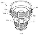
- the actuator body 12 includes a screwing part 121 screwed to the valve body 11, an exposed part 122 exposed to the outside, and a screwing part 123 screwed to the cap body 131 of the casing 13. .
- a screw is cut on the outer peripheral surface of the screw part 121 and is screwed with a screw cut on the inner peripheral surface of the valve body 11. Further, a screw is also cut on the outer peripheral surface of the screwing portion 123, and screwed with a screw cut on the inner peripheral surface of the cap body 131.
- wiring grooves 121a, 122a, and 123a through which wiring can be passed are formed along the axial direction.
- the groove bottoms of the wiring grooves 121a and 123a provided on the outer peripheral surfaces of the screwing portions 121 and 123 are deeper than the screw grooves cut on the outer peripheral surfaces. Therefore, the valve body 11 and the cap body 131 can be screwed into the screwing portions 121 and 123, respectively, without disconnecting the wiring in a state where the wiring is passed through the wiring grooves 121a and 123a.
- a screw hole 122b for attaching the cover 1221 is provided beside the wiring groove 122a provided on the outer peripheral surface of the exposed portion 122.
- the cover 1221 is a member that covers the wiring groove 122 a and includes a through hole 1221 a corresponding to the screw hole 122 b of the actuator body 12.
- the wiring is passed through the wiring groove 122a of the actuator body 12 by passing the wiring through the wiring groove 122a of the actuator body 12 and screwing the screw 122c into the screw hole 122b of the actuator body 12 through the through hole 1221a of the cover 1221. Is covered with a cover 1221.
- a disk 124 that presses the diaphragm 113, a presser adapter 125 that presses the periphery of the diaphragm 113, a piston 126 that slides up and down, and an outer peripheral surface of the piston 126 are wound, and the piston 126 is attached downward.
- An energizing spring 127 is provided.
- the presser adapter 125 presses the periphery of the diaphragm 113 from above to prevent the fluid flowing in the flow path 111 from leaking into the actuator body 12 from the vicinity of the periphery of the diaphragm 113.
- the piston 126 causes the diaphragm 113 to contact and separate from the sheet 112 via the disk 124.
- the substantially central portion of the piston 126 in the axial direction is enlarged in a disc shape, and the portion constitutes an enlarged diameter portion 1261.
- the piston 126 receives a biasing force of the spring 127 on the upper surface side of the enlarged diameter portion 1261.
- a drive pressure introduction chamber S ⁇ b> 2 is formed between the lower end side of the enlarged diameter portion 1261 and the upper end surface of the actuator body 12.
- a driving pressure introduction path 126b for communicating the opening 126a formed on the upper end surface with the driving pressure introduction chamber S2 formed on the lower end side of the enlarged diameter portion 1261.
- An introduction pipe 21 for introducing a driving pressure from the outside is connected to the opening 126 a of the piston 126.
- a small-diameter holding portion is provided on the outer peripheral surface of the enlarged diameter portion 1261 of the piston 126, and an O-ring 1262 is held by the holding portion.
- the O-ring 1262 seals between the outer peripheral surface of the piston 126 and the inner peripheral surface of the actuator body 12.
- a holding portion having a small diameter is also provided on the lower end side of the piston 126, and an O-ring 1263 is held by the holding portion.
- the O-ring 1263 seals between the outer peripheral surface of the piston 126 and the inner peripheral surface of the actuator body 12.
- a space S ⁇ b> 1 partitioned by the diaphragm 113 and the O-ring 1263 is formed in a portion where the disk 124 in the actuator body 12 moves up and down.
- a through hole 12 a is formed in the screwing portion 121 of the actuator body 12, and the space S 1 communicates with the outside through the leak port LP provided in the valve body 11 by the through hole 12 a.
- the leak port LP is blocked, the leak port LP is blocked from the outside and becomes airtight.
- a space formed by the O-ring 1262 and the O-ring 1263 forms a driving pressure introduction chamber S2 that communicates with the driving pressure introduction passage 126b in the piston 126.
- Air is introduced into the drive pressure introduction chamber S2 from the introduction pipe 21 via the drive pressure introduction path 126b in the piston 126.
- the piston 126 is pushed upward against the biasing force of the spring 127.
- the diaphragm 113 is separated from the seat 112 and opened, and the fluid flows.
- the piston 126 is pushed downward according to the urging force of the spring 127.
- the diaphragm 113 comes into contact with the seat 112 and closes, and the fluid flow is blocked.
- the casing 13 is a substantially cylindrical member with one end closed, and is disposed at the upper end of the actuator body 12 to process data obtained from the pressure sensor 41, the temperature sensor 42, and the limit switch 43.
- Module 5 is housed inside.
- the casing 13 in this example is composed of three members, that is, a cap body 131, an actuator cap 132, and a cap top 133.
- the cap body 131 is a substantially cylindrical member, and is disposed at the upper end of the actuator body 12.
- the outer peripheral surface of the upper end portion of the actuator body 12 and the inner peripheral surface of the lower end portion of the cap body 131 are threaded corresponding to each other. By screwing together, the cap body 131 is placed on the actuator body 12. Is fixed.
- a fixing member 1311 is attached to the inner peripheral surface of the cap body 131.
- the fixing member 1311 is a member for fixing a limit switch 43 described later, and has a substantially rectangular parallelepiped shape.
- the fixing member 1311 is provided with a screw hole 1311a for attaching the fixing member 1311 to the inner peripheral surface of the cap body 131.
- the cap body 131 is provided with a through hole 131a.
- the screw 1311b is screwed into the through hole 131a of the cap body 131 from the outside, and the screw 1311b is screwed into the screw hole 1311a of the fixing member 1311 disposed on the inner peripheral surface of the cap body 131. Fixed.
- the fixing member 1311 is provided with a wiring groove 1311 c for routing a wiring derived from a limit switch 43 described later, and the wiring can be accommodated in the wiring groove 1311 c. .
- the actuator cap 132 is a substantially disk-shaped member disposed at the upper end of the cap body 131, and partitions the casing 13 up and down.
- the actuator cap 132 holds the spring 127 and the upper surface of the enlarged diameter portion 1261 of the piston 126 on the lower surface side.
- a substantially cylindrical through hole 132a extending toward the piston 126 is provided at a position corresponding to the opening 126a of the piston 126 in the center of the actuator cap 132.
- One end of the introduction tube 21 is inserted into the through hole 132a.
- a through hole 132 b for passing wiring is provided outside the through hole 132 a.
- the cap top 133 is a substantially cap-shaped member disposed at the upper end of the actuator cap 132, and the information processing module 5 can be accommodated in the hollow interior.
- Through holes 133 a and 133 b are provided on the top surface of the cap top 133.
- a liquid crystal panel or the like for displaying data acquired by the pressure sensor 41, the temperature sensor 42, and the limit switch 43, a processing result based on the data, and the like are fitted in the through hole 133a.
- a warning light such as a lamp is fitted.
- a through hole 133 c is provided on the side surface of the cap top 133.
- the through-hole 133c is provided with a connector for connecting to an external device in order to take out data acquired by the temperature sensor 42 and the limit switch 43, a processing result based on the data, and the like.
- a through hole 133d is provided at a position away from the upper surface of the cap top 133 on the side surface of the cap top 133 and in the vicinity of the opening on the actuator cap 132 side.
- the introduction pipe 21 is inserted through the through hole 133d.
- the introduction pipe 21 is a pipe for introducing air as a driving pressure into the fluid control device 1 from the outside, and is constituted by a nylon tube or the like and has flexibility.
- One end of the introduction pipe 21 is inserted into the driving pressure introduction path 126b from the opening 126a of the piston 126.
- An O-ring 24 is held between the outer peripheral surface at the tip of the introduction pipe 21 inserted into the drive pressure introduction path 126b and the inner peripheral surface of the drive pressure introduction path 126b.
- the O-ring 24 seals between the inner peripheral surface of the driving pressure introduction passage 126b and the outer peripheral surface of the introduction pipe 21 inserted into the driving pressure introduction passage 126b.
- a fixing member 23 for fixing the introduction tube 21 is fitted in the through hole 132a of the actuator cap 132.
- the fixing member 23 is a substantially cylindrical member, and has a through hole having an inner diameter substantially the same as the outer diameter of the introduction tube 21, and the introduction tube 21 is inserted into the through hole. Further, the periphery of the fixing member 23 on the opening 126a side is pointed like a claw, so that the introduction tube 21 inserted through the fixing member 23 is fixed so as not to come out.
- the holding member 3 is held near the opening on the actuator cap 132 side of the cap top 133.
- the holding member 3 is a substantially ring-shaped member having flexibility made of resin, and the information processing module 5 is capped by supporting the information processing module 5 upward from the lower surface side. Hold in top 133.
- the holding member 3 is formed with through holes 3a and 3b penetrating in the vertical direction. In the through holes 3a and 3b, a pressure sensor 41, a temperature sensor 42, a limit switch 43, and the information processing module 5 are formed. Can be passed through the wiring to connect.
- a protruding portion 31 is formed on the outer peripheral edge of the holding member 3 so as to protrude outward in a claw shape.
- the holding member 3 including the protruding portion 31 has an outer diameter that is substantially the same as or slightly larger than the inner diameter of the hollow portion of the cap top 133. Accordingly, as shown in FIG. 7, when the holding member 3 is attached to the inner peripheral surface of the cap top 133, the holding member 3 is held in a state of being stretched on the inner peripheral surface of the cap top 133 by the protruding portion 31. Is done.
- the holding member 3 is held near the opening of the cap top 133 on the actuator cap 132 side and above the position where the through hole 133d is provided. Thereby, the information processing module 5 is held on the holding member 3 so that the introduction tube 21 is not crushed by the information processing module 5.
- the diameter of the through hole 3a is increased and the holding member 3 is formed in a substantially ring shape so that the holding member 3 can be easily bent and attached to the inner peripheral surface of the cap top 133.
- the holding member 3 can be formed into a substantially disk shape in which only a small hole for passing wiring is provided, or the holding member 3 is a member formed integrally with the cap top 133. It can also be.
- the holding member 3 is configured integrally with the cap top 133, it is preferable that the entire upper surface of the cap top 133 is openable and closable so that the information processing module 5 can be accommodated from the upper surface.
- a pressure sensor 41, a temperature sensor 42, and a limit switch 43 are attached at predetermined locations, and data detected by the pressure sensor 41, the temperature sensor 42, and the limit switch 43 is stored.
- the information processing module 5 to be processed is stored.
- a pressure sensor 41 for detecting the pressure in the space S1 and a temperature sensor 42 for measuring the temperature of the fluid are attached to the space S1.
- the pressure sensor 41 includes a pressure-sensitive element that detects a pressure change in the space S1, a conversion element that converts a detected pressure value detected by the pressure-sensitive element into an electrical signal, and the like.
- the pressure sensor 41 detects a change in pressure in the space S1 to detect an abnormality of the fluid control device 1 due to fluid leakage or the like.
- a condenser microphone unit is used as the pressure sensor 41.
- the condenser microphone unit has a diaphragm that vibrates in response to sound waves, and a counter electrode that is disposed to face the diaphragm, and changes the electrostatic capacitance between the diaphragm and the counter electrode. It can be converted into a change into an audio signal.
- the condenser microphone unit becomes non-directional (omnidirectional) by closing an air chamber provided on the back side of the diaphragm. In the case of omnidirectionality, the condenser microphone unit operates by detecting changes in sound pressure due to sound waves from all directions, and thus can be used as the pressure sensor 41.
- the temperature sensor 42 measures the temperature of the installation location. Since the installation location is in the vicinity of the flow path 111, the temperature of the installation location can be regarded as the temperature of the fluid flowing through the flow path 111.
- a limit switch 43 is attached inside the cap body 131 of the casing 13.
- the limit switch 43 is fixed in the cap body 131 by a fixing member 1311 attached to the inner peripheral surface of the cap body 131.
- the limit switch 43 is fixed above the enlarged diameter portion 1261 of the piston 126, and the switch is switched according to the vertical movement of the piston 126. That is, when the piston 126 is pushed upward when the valve is opened, the limit switch 43 is pressed by the diameter-enlarged portion 1261 of the piston 126. On the other hand, when the piston 126 is pushed downward when the valve is closed, the limit switch 43 is released from a state where the limit switch 43 is pushed down by the enlarged diameter portion 1261 of the piston 126.
- the opening / closing frequency and opening / closing frequency of the fluid control device 1 can be detected in response to pressing of the limit switch 43 accompanying the vertical movement of the piston 126. Further, by providing a plurality of limit switches 43, the opening / closing speed of the fluid control device 1 can be detected.
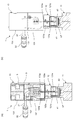
- the wiring of the pressure sensor 41, the temperature sensor 42, the limit switch 43 and the information processing module 5 will be described with reference to FIGS. 8 and 9.
- the wiring led out from the pressure sensor 41 and the temperature sensor 42 is drawn into the cap body 131 through the wiring grooves 121a, 122a, 123a formed on the outer peripheral surface of the actuator body 12. Since the wiring grooves 121a, 122a, 123a are respectively covered with the valve body 11, the cover 1221, and the cap body 131, the wiring routed from the pressure sensor 41 and the temperature sensor 42 into the cap body 131 is exposed to the outside. There is nothing. Further, the wiring led out from the limit switch 43 is fitted into the wiring groove 1311c of the fixing member 1311 shown in FIG. 5 and then drawn into the cap body 131.
- the wires of the pressure sensor 41, the temperature sensor 42, and the limit switch 43 drawn into the cap body 131 are drawn into the cap top 133 through the through hole 132b provided in the actuator cap 132, and the information processing module Connect to 5.
- the wiring is routed without exposing the wiring to the outside and without contacting the movable member such as the piston 126 in the fluid control device 1. Disconnection due to contact or the like can be prevented.
- the information processing module 5 includes an LSI (Large-Scale Integration) or the like for processing data detected by the pressure sensor 41, the temperature sensor 42, and the limit switch 43.
- the information processing module 5 may include a driving power source such as a button battery that supplies power necessary for driving the pressure sensor 41, the temperature sensor 42, and the limit switch 43.
- a plurality of fluid control devices 1 having the above configuration are usually integrated to constitute a fluid control device 10.
- the fluid control devices 1 are densely arranged, so that a panel for displaying data in each fluid control device 10 and information
- a port for connecting an external device such as a USB memory is provided on the upper surface, at least above.
- a panel for displaying data is difficult to view unless viewed from above.
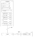
- the information processing module 5 includes a determination processing unit 51, a correction processing unit 52, an information display unit 53, a warning display unit 54, and an information supply unit 55, as shown in FIG.
- the discrimination processing unit 51 is a functional unit that executes processing for discriminating whether there is an abnormality in the fluid control device 1 based on data acquired by the pressure sensor 41, the temperature sensor 42, and the limit switch 43.
- the discrimination processing unit 51 compares the predetermined threshold value held in the reference table with the detected value of the pressure detected by the pressure sensor 41, so that the fluid caused by the fluid leakage into the space S1 or the like
- a process for determining an abnormality of the control device 1 can be executed. That is, during normal use, the limit value of the pressure in the space S1 assumed when the valve of the fluid control device 1 is opened and closed is set as a predetermined threshold value.
- the detected value of the pressure in the space S1 exceeds the threshold value, it is determined that an abnormality has occurred in the fluid control device 1.
- the rationality of such determination is that the pressure in the space S1 has decreased as a result of the fluid leaking into the space S1 due to the breakage of the diaphragm 113 and the like, or the pressure in the space S1 has increased, or due to the reduced pressure in the channel 111.
- the detected pressure value in the space S1 can be regarded as exceeding the threshold value.
- the correction processing unit 52 corrects a predetermined threshold that the discrimination processing unit 51 refers to in order to discriminate the leakage of the fluid into the space S1, according to the temperature of the fluid measured by the temperature sensor 42.
- the discrimination processing unit 51 compares the corrected threshold value with the detected pressure value detected by the pressure sensor 41.
- determines abnormality of the fluid control apparatus 1 resulting from the fluid leakage to S1, etc. is performed.
- the information display unit 53 includes information relating to the pressure in the space S1 acquired by the pressure sensor 41, the temperature sensor 42, and the limit switch 43, the temperature of the fluid, the open / close state and the number of times of the fluid control device 1, and the discrimination processing. It is a function part which displays the information which concerns on the result of the discrimination
- the information display unit 53 is realized by a liquid crystal panel or the like, and is fitted into the through hole 133 a of the cap top 133. Thereby, the condition of the fluid control device 1 can be easily grasped from the outside.
- the information display unit 53 is disposed on the upper surface side where each fluid control device 1 is most easily identified, so that the displayed information can be easily confirmed.
- the warning display unit 54 is a functional unit that emits light when an abnormality occurs in the fluid control device 1 in response to the result of the discrimination processing by the discrimination processing unit 51.
- the warning display unit 54 is realized by a light emitter such as an LED, and is fitted into the through hole 133b of the cap top 133. Thereby, when an abnormality occurs in the fluid control device 1, the warning display unit 54 issues a warning, and the abnormality can be easily recognized.
- the information supply unit 55 is a functional unit for supplying data acquired by the pressure sensor 41, the temperature sensor 42, and the limit switch 43 and information related to the determination result by the determination processing unit 51 to the outside. This function unit is used by connecting to an external computer with a USB cable, and the USB connector is inserted and removed through a through hole 133 c on the side surface of the cap top 133.
- the fluid control device 1 configured as described above, based on a comparison between the pressure in the space S1 detected by the pressure sensor 41 and a predetermined threshold value, the fluid control device 1 caused by fluid leakage into the space S1 or the like. Can be detected. Furthermore, since the fluid control device 1 detects the pressure in the space S1 and detects an abnormality of the fluid control device 1 by comparing a predetermined threshold value with a detection value, the inside of the closed space S becomes a negative pressure. Even if an abnormality occurs, this can be detected.
- the pressure in the space S1 changes due to the temperature change of the fluid, this is distinguished from the change in the pressure in the space S1 caused by an abnormality of the fluid control device 1 such as fluid leakage.
- the abnormality of the fluid control device 1 can be detected.
- the space partitioned by the diaphragm 113 and the O-ring 1262 is defined as the space S1, and the abnormality of the fluid control device 1 is detected by detecting the pressure inside the space S1, but the fluid control device separated by the diaphragm 113 is detected. If it is a space within 1, the pressure of the space S1 is detected to detect the pressure, so that an abnormality of the fluid control device 1 such as a breakage of the diaphragm 113 can be detected.
- a driving pressure sensor that detects the driving pressure of the fluid control device 1 is provided, thereby opening / closing the fluid control device 1. Can also be detected.
- a pressure change in the space S1 due to fluid leakage or the like it is possible to determine a pressure change in the space S1 due to fluid leakage or the like. That is, it is possible to correct a transient pressure change in the space S1 at the moment when the piston 126 is moving by experimentally obtaining an appropriate transfer function for converting the driving pressure into a necessary correction value.
- the detected value of the pressure sensor 41 does not increase even though a pressure increase in the space S1 is expected from the detected value of the driving pressure sensor, it is possible to determine whether the piston 126 or the pressure sensor 41 has failed. it can.
- the information display panel is fitted in the through hole 133a on the upper surface of the cap top 133.
- an information outlet such as a USB connector can be provided in the through hole 133a.
- an abnormality of the fluid control device 1 is detected by the discrimination processing unit 51 and the correction processing unit 52 included in the built-in information processing module 5, and the information is displayed as an information display unit 53 and warning display.
- the information is provided to the outside via the unit 54 or the information supply unit 55, the information can be provided to a server configured to be communicable via a network.
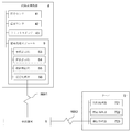
- FIG. 12 shows an example in which the fluid control device 1 and the server 71 can communicate with each other via the networks NW1 and NW2.
- the information processing module 5 includes a communication processing unit 56 so that the fluid control device 1 can transmit and receive data to and from the server 71.
- the communication processing unit 56 transmits the determination result of the determination processing unit 51 to the server 71, and transmits data acquired by the pressure sensor 41, the temperature sensor 42, and the limit switch 43 as necessary.
- the relay device 6 is provided between the fluid control device 1 and the server 71, and information from the fluid control device 1 is provided to the server 71 via the relay device 6.
- data transmitted by the communication processing unit 56 is temporarily transmitted to the relay device 6 via the network NW1 realized by wireless communication such as Bluetooth (registered trademark), infrared communication, or Zigbee (registered trademark). Then, the data is transmitted from the relay device 6 to the server 71 via the network NW2 realized by a wireless or wired LAN or the like.
- the communication processing unit 56 can transmit the determination result by the determination processing unit 51 at a predetermined cycle arbitrarily set such as one hour or one day. Thus, when information is transmitted at a predetermined cycle, power consumption can be suppressed.
- the communication processing unit 56 included in the information processing module 5 of each fluid control device 1 is connected to the server 71.
- the discrimination result by the discrimination processing unit 51 can be transmitted for each fluid control device 1 at different timings.
- any of the plurality of fluid control devices 1 constituting the fluid control device 10 is abnormal because the self-identification information capable of individually identifying the fluid control devices 1 is transmitted to the server 71. Can be determined. Further, the determination result is transmitted to the server 71 at different timings for each fluid control device 1, so that the problem of packet collision can be avoided, and it is temporary compared to the case where the determination result is transmitted all at once. Processing overload can also be prevented. In addition, unlike the case where data are transmitted all at once, there is no need to change the wireless channel used for data transmission for each fluid control device 1, and thus it is not necessary to prepare many channels. In particular, when the network NW1 is configured by Bluetooth (registered trademark), the number of simultaneously connected devices is limited (usually 7), so the number of fluid control devices 1 exceeding the number of simultaneously connected devices can be used by changing the transmission timing. Can do.
- the server 71 includes a CPU (Central Processing Unit), a computer program executed by the CPU, a RAM (Random Access Memory) and ROM (Read Only Memory) for storing the computer program and predetermined data, and an external storage device such as a hard disk drive. It consists of hardware resources.
- the server 71 includes a communication processing unit 711 for receiving the determination result of fluid leakage in the space S1 of the fluid control device 1 via the relay device 6. Information received from the fluid control device 1 by the server 71 is appropriately provided to a terminal used by the monitor or the like in response to a request from a terminal used by the monitor or the like of the fluid control device 1.
- the relay device 6 receives data from the fluid control device 1 via the network NW1, and transmits the received data to the server 71 via the network NW2.
- the relay device 6 is interposed between the fluid control device 1 and the server 71.
- the fluid control device 1 and the server 71 may be configured to be capable of direct data communication.
- information related to the abnormality of the fluid control device 1 is collected in the server 71, so that a monitor of the fluid control device 1 can monitor the operation status of the fluid control device 1 without burden.
- FIG. 13 shows an example in which the fluid control device 8 and the server 72 are configured to communicate with each other via a network.
- the fluid control device 8 has the same structure as that of the fluid control device 1, and unless otherwise specified, members and functions having the same numbers (symbols) as those in the above example are used.
- the units and the like have the same functions as the above-described members and functional units, or perform processing, and thus description thereof will be omitted.
- the server 72 includes a discrimination processing unit 721 and a correction processing unit 722 having the same functions as the discrimination processing unit 51 and the correction processing unit 52 provided in the information processing module 5 of the fluid control device 1 described above. Abnormality of the fluid control device 8 caused by fluid leakage into the space S1 is determined on the server 72 side.
- the fluid control device 8 transmits data obtained by the pressure sensor 41, the temperature sensor 42, and the limit switch 43 to the server 72 by the communication processing unit 56 of the information processing module 9.
- the server 72 includes a CPU, a computer program executed by the CPU, RAM and ROM for storing the computer program and predetermined data, and hardware resources such as an external storage device such as a hard disk drive.
- a functional unit including the unit 722 and the communication processing unit 723 is configured.
- the discrimination processing unit 721 compares the predetermined threshold value held in the reference table or the like with the detected pressure value detected by the pressure sensor 41, so that the space S1 is stored. A process of determining an abnormality of the fluid control device 8 due to fluid leakage or the like is executed. In addition, when the predetermined threshold is corrected by the correction processing unit 722, a process of determining an abnormality of the fluid control device 8 is executed based on the corrected threshold.
- the correction processing unit 722 is operated by the discrimination processing unit 51 in accordance with the open / close state of the fluid control device 8 detected by the limit switch 43 and the temperature of the fluid measured by the temperature sensor 42.
- a predetermined threshold value that is referred to in order to determine the leakage of fluid into the space S1 is corrected.
- the information on the open / close state of the fluid control device 8 and the fluid temperature measured by the temperature sensor 42 is supplied from the fluid control device 8 to the server 72 via the networks NW1 and NW2. Is.
- the communication processing unit 723 receives information regarding the open / close state of the fluid control device 8 and the temperature of the fluid measured by the temperature sensor 42 from the fluid control device 8 via the relay device 6.
- the configuration of the information processing module 9 mounted on the fluid control device 8 can be simplified. Maintenance such as debugging of programs executed by the processing unit 721 and the correction processing unit 722 is facilitated.
- the abnormality occurrence information is The information may be transmitted to the control device 8 so that the information display unit 53 and the warning display unit 54 of the fluid control device 8 display an abnormality or warn.
- the fluid control device 8 and the server 72 are configured to communicate with each other via the networks NW1 and NW2, information acquired by the pressure sensor 41, the temperature sensor 42, and the limit switch 43 provided in the fluid control device 8. Therefore, data mining can be performed based on the aggregated information.
- a system for analyzing the operation of the fluid control device 8 will be described as a modification of the above-described embodiment in which the fluid control device 8 and the server 72 are configured to be communicable.
- the fluid control device 8 includes a pressure sensor 41, a temperature sensor 42, and a limit switch 43 as an operation information acquisition mechanism for acquiring operation information of the fluid control device 8.
- the fluid control device 8 acquires the operation information of the fluid control device 8 such as the pressure in the space S1, the temperature of the fluid, the number of opening and closing of the fluid control device 8 and the opening and closing frequency (the opening and closing speed can be detected by a plurality of limit switches). can do.
- the fluid control device 8 in order to analyze the operation of the fluid control device 8, it is also effective to acquire other types of operation information by providing a predetermined operation information acquisition mechanism. Specifically, the usage period of the fluid control device 8, the temperature and humidity of the external environment of the fluid control device 8, the thrust of the piston 126, the average moving speed of the piston 126, vibration, and the internal stress of the members constituting the fluid control device 8 And hardness.
- FIG. 14 shows the configuration of an operation analysis system for a fluid control device according to this example.
- the server 72 is an information processing apparatus that performs data mining based on information acquired from the fluid control device 8, and in addition to the above-described discrimination processing unit 721, correction processing unit 722, and communication processing unit 723.
- the information collection unit 724 uses the communication processing unit 723 to request the fluid control device 8 to transmit operation information, and collects the information.
- the information collection unit 724 requests the supply of information related to the abnormality determination result of the fluid control device 8 from the abnormality determination processing unit 721 and collects information related to the abnormality determination result.
- the operation information in the fluid control device 8 may be collected not only from the fluid control device 8 but also from other devices. For example, it may be collected from a terminal that measures the temperature and humidity of a place where the fluid control device 8 is installed, or information input by an administrator terminal of the administrator of the fluid control device 8 may be collected. Also good.
- the information storage unit 725 is a storage unit that stores operation information collected from the fluid control device 8 and a determination result of abnormality of the fluid control device 8.
- the information extraction unit 726 refers to the information storage unit 725 and selectively extracts, for each fluid control device 8, information related to the determination result and other operation information having the same predetermined operation information as the analysis target. .
- information related to the operation time at the same valve opening / closing frequency for example, 10 million times
- the abnormality determination result in the operation time is extracted.
- the data at a predetermined time before and after the switching of the open / close state of the fluid control device 8 detected from the change of the limit switch 43 and the pressure sensor 41 is cut out and input data. And This reflects the fact that measuring changes in the dynamic sensor readings during valve operation is effective in anticipation of abnormalities.
- the predetermined time is defined as the time required for opening and closing the fluid control device 8 (the time from when the drive pressure is introduced until the fluid control device 8 is fully opened. The time between the two dotted lines in FIG. By setting the time to 1 to 5 times the time (which corresponds to this time), the necessary range of data can be extracted without waste. Further, by transmitting the data transmitted from the fluid control device 8 in advance within the range of this time, the amount of communication data can be reduced, and the power consumption in the fluid control device 8 can be suppressed.
- the correlation analysis unit 727 analyzes the correlation between the predetermined operation of the fluid control device 8 and the occurrence of abnormality by comparing the information extracted by the information extraction unit 726.
- the fluid in which the abnormality has occurred Based on past operation information of the control device 8, input data for a predetermined period before the occurrence of an abnormality (hereinafter referred to as the period immediately before the failure), input data after the occurrence of the abnormality, and previous normal operation Perform supervised learning to classify input data.
- This learning is performed by, for example, a stochastic gradient descent (SGD) method using a backpropagation method for a neural network model.
- SGD stochastic gradient descent
- the discriminating performance of the learned model varies depending on the setting of the length of the period immediately before the failure, and the length of the predetermined period is a hyperparameter that should be adjusted in the same manner as the hyperparameters such as the number of layers and the number of nodes of the neural network. Adjustment of these hyper parameters is selected by, for example, an optimization algorithm, and a value with high discrimination capability can be selected.
- the operation time required to open and close the valve 10 million times and the same 10 million valve opening / closing times based on the determination result of abnormality in the operation time Even so, it is possible to analyze whether or not the occurrence probability of the abnormality differs depending on whether it is the number of times counted in three months or the number of times counted in three years.
- unsupervised learning using an auto encoder is performed in order to detect in advance a special abnormality with a small number of data.
- the auto encoder inputs the input data when the valve is operating normally to the model configured by the neural network, and performs learning so that the same data is output. Learning the auto encoder that can reproduce the original data appropriately only for the pattern of the input data during normal operation by setting the dimension of the hidden layer of this neural network smaller than the dimension of the input data and output data Can be made.
- the abnormality prediction unit 728 calculates the abnormality occurrence probability of the fluid control device 8 with reference to the operation information of the fluid control device 8 stored in the information storage unit 725 based on the analysis result by the correlation analysis unit 727. Thus, an abnormality of the fluid control device 8 is expected.
- the probability that the valve is in the period immediately before the failure can be calculated by classifying the learned model obtained by the first learning with the measured value of the current sensor data as an input (first abnormality prediction means 7281). ). This probability is a probability of occurrence of an abnormality that breaks within a predetermined period when the reading is changed.
- the input data obtained from the current sensor is passed through the auto encoder obtained by the second learning, the output is compared with the original input, the distance between the input and output is calculated using the L2 norm, etc. Compare (second abnormality expecting means 7282).
- the auto encoder is configured so that the original data can be restored if the data is in normal operation.However, since the original data cannot be restored correctly in abnormal operation, the difference between input and output becomes large. If it exceeds, an abnormality of the fluid control device 8 can be detected.
- the fluid control device 8 is often placed in a completely different operating environment due to modification of a device on which the fluid control device 8 is mounted, and can be used as index data indicating whether or not re-learning should be performed.
- the information is notified to an administrator terminal used by the administrator of the fluid control device 8, or the information is notified to the fluid control device 8, and the warning display unit 54 May be displayed.
- the server 72 includes the discrimination processing unit 721 and the correction processing unit 722 has been described.
- the fluid control device 8 includes a functional unit similar to the discrimination processing unit 721 and the correction processing unit 722.
- the information collection unit 724 collects the abnormality determination result from the fluid control device 8.
- Correlation between frequency of opening and closing of fluid control device 8 and occurrence of abnormality For example, the probability of occurrence of abnormality is expected to differ between 10 million valve opening / closing in 3 years and 10 million valve opening / closing in 3 months Is done.
- Correlation between environmental temperature and occurrence of abnormality For example, it is expected that the occurrence probability of abnormality is different between use in an environment of 20 ° C and use at 80 ° C.
- Correlation between distortion of members constituting fluid control device 8 and occurrence of abnormality For example, it is expected that the probability of occurrence of abnormality differs depending on the internal stress of each member.
- Correlation between humidity and occurrence of abnormality For example, the probability of occurrence of abnormality is different between humidity and each member, in particular, the O-rings 1262, 1263, and 24.
- Correlation between initial hardness and hardness change and occurrence of abnormality For example, it is expected that the probability of occurrence of abnormality differs depending on the initial hardness of each member in the initial stage of use of fluid control device 8.
- the probability of occurrence of abnormality is expected to vary depending on the hardness change rate.
- processing equivalent to extraction of a predetermined frequency component, calculation of cross-correlation between multiple sensor data, matching with a predetermined pattern, integration, differentiation, etc. may be included for each sensor measurement value. May be a model.
- which member is abnormal such as damage to the diaphragm 113 (for example, damage to the diaphragm 113, damage to the O-rings 1262, 1263, 24, piston 126) It is also possible to grasp which member is likely to be affected by a change in valve opening / closing speed, a change in flow rate, a stationary piston, etc. it can.
- the occurrence of an abnormality may be expected by the above data mining, and the comparison information may be compared and analyzed for the presence or absence of an abnormality that has actually occurred to improve the accuracy of the correlation analysis.
Landscapes
- Engineering & Computer Science (AREA)
- General Engineering & Computer Science (AREA)
- Mechanical Engineering (AREA)
- Physics & Mathematics (AREA)
- Fluid Mechanics (AREA)
- Fluid-Pressure Circuits (AREA)
- Fluid-Driven Valves (AREA)
- Valve Housings (AREA)
- Indication Of The Valve Opening Or Closing Status (AREA)
Abstract
Description
しかし、そのような薄膜の微細化は流体制御機器に今まで以上の高頻度な開閉動作を要求しており、その負荷により流体の漏出等を惹き起こしやすくなる場合がある。そのため、流体制御機器における流体の漏出を容易に検知できる技術への要求が高まっている。
また、漏出を容易に検知できるだけでなく、従来は考慮していなかった流体制御機器の使用頻度、温度、湿度、及び振動等、上記漏出を始めとして流体制御機器の異常に影響を及ぼす様々な環境要因情報を収集し、異常との相関を分析し、異常発生の予期に役立てることが可能な流体制御機器、及び情報収集方法の要求が高まっている。
また、半導体製造プロセスにおいては反応性が高く極めて毒性の高いガスが使われるため、遠隔的に漏出を検知できることが重要である。
また、上述のALDを実現するためには流体制御機器とプロセスチャンバの配管接続距離が重要になっている。即ち、プロセスガスの制御をより高速化するために、流体制御機器をさらに小型化しプロセスチャンバの直近に配置することが重要になっている。
また、特許文献2では、流体の流量を制御する制御器の外面に形成された孔とこの孔に取付けられる漏洩検知部材とからなるシール部破損検知機構付制御器であって、前記孔は制御器内の空隙に連通し、前記漏洩検知部材は特定の流体の存在によって感応するものが提案されている。
さらに、特許文献3では、流体の漏れを検出する漏れ検出装置であって、センサ保持体と、漏れ検出対象部材に設けられて漏れ検出対象部材内の密封部分と外部とを連通するリークポートに対向するようにセンサ保持体に保持された超音波センサと、超音波センサのセンサ面とリークポートとの間に設けられた超音波通路と、超音波センサで得られた超音波を処理する処理回路とを備えているものが提案されている。
また、流体制御機器の異常を検知する部材同士を接続する配線が外側に露出している場合、配線同士の絡まりが生じたり、ショートが引き起こされたりして、流体制御機器そのものに不具合を生じさせる原因ともなりかねない。
また、流体制御機器の異常を検知するための部材等が内部に収容された構造においても、異常の検知結果は、流体制御機器の外部において容易に確認できることが好ましい。
また、上記装置はいずれも異常の発生後にしかセンサデータの変化が発生しないため、故障の発生を予期する事ができない。
なお、以下の説明では、便宜的に図面上での方向によって部材等の方向を上下左右と指称することがあるが、これらは本発明の実施あるいは使用の際の部材等の方向を限定するものではない。
図1に示されるように、本実施形態に係る流体制御機器1は、流体制御機器1の異常、特に流体の漏出を検知するセンサやセンサの駆動に関わるモジュール等を内蔵し、上方に動作状況を表示するパネルや動作状況に関わる情報を取り出すための取出口を備えたものである。
一方、駆動圧としてのエアの供給が止まってダイヤフラム113がディスク124に押圧されると、シート112に対してダイヤフラム113の中央部がシート112に当接する方向に変位してシート112に当接する。その結果、弁室111cが遮断され、流入路111aと流出路111bが遮断された状態となる。
一方、本例のようなダイレクトダイヤフラム構造、即ち、ダイヤフラム113がシート112に当接離反することによって流入路111aから流出路111bへ流体を流通させたり、流通を遮断させたりする構造では、アクチュエータボディ12内の体積変化が少ない。そのため、流体制御機器1の異常を検知するべく、アクチュエータボディ12内に後述する圧力センサ41を取り付けて圧力変化を検出する場合に、リークポートLPを塞いでも、流体制御機器1は問題なく開閉動作を行うことができる。
螺合部121の外周面にはネジが切られており、バルブボディ11の内周面に切られたネジと螺合する。
また、螺合部123の外周面にもネジが切られており、キャップボディ131の内周面に切られたネジと螺合する。
ここで、図4に示されるように、カバー1221は配線溝122aを覆う部材であって、アクチュエータボディ12のネジ穴122bに対応した貫通孔1221aを備えている。アクチュエータボディ12の配線溝122aに配線を通し、カバー1221の貫通孔1221aを介して、アクチュエータボディ12のネジ穴122bにネジ122cを螺合させることにより、アクチュエータボディ12の配線溝122aに通した配線がカバー1221で覆われる。
このピストン126の軸心方向略中央は円盤状に拡径しており、当該箇所は拡径部1261を構成している。ピストン126は、拡径部1261の上面側においてバネ127の付勢力を受ける。また、拡径部1261の下端側においては、アクチュエータボディ12の上端面との間に駆動圧導入室S2を形成する。
ピストン126の開口部126aには、外部から駆動圧を導入するための導入管21が接続される。
ここで、アクチュエータボディ12の螺合部121には貫通孔12aが形成されており、この貫通孔12aによって空間S1は、バルブボディ11に設けられたリークポートLPを介して外部と連通しているが、リークポートLPが塞がれると、外部と遮断されて気密状態となる。
この駆動圧導入室S2には、ピストン126内の駆動圧導入路126bを介して、導入管21からエアが導入される。エアが駆動圧導入室S2に導入されると、ピストン126がバネ127の付勢力に抗して上方に押し上げられる。これにより、ダイヤフラム113がシート112から離反して開弁した状態となり、流体が流通する。
一方、駆動圧導入室S2にエアが導入されなくなると、ピストン126がバネ127の付勢力に従って下方に押し下げられる。これにより、ダイヤフラム113がシート112に当接して閉弁した状態となって、流体の流通が遮断される。
本例におけるケーシング13は、キャップボディ131、アクチュエータキャップ132、キャップトップ133の3つの部材によって構成されている。
固定部材1311は、後述するリミットスイッチ43を固定するための部材であって、略直方体状からなる。この固定部材1311には、固定部材1311をキャップボディ131の内周面に取り付けるためのネジ穴1311aが設けられている。
これに対応して、キャップボディ131には貫通孔131aが設けられている。キャップボディ131の貫通孔131aに外側からネジを貫挿させ、キャップボディ131の内周面上に配設された固定部材1311のネジ穴1311aにネジ1311bを螺合させることにより、固定部材1311が固定される。
このアクチュエータキャップ132は、下面側において、ピストン126の拡径部1261の上面とバネ127を挟持している。
さらに、貫通孔132aの外側には、図6に示されるように、配線を通すための貫通孔132bが設けられている。
貫通孔133aには、圧力センサ41、温度センサ42、及びリミットスイッチ43によって取得されたデータや当該データに基づく処理結果等を表示するための液晶パネル等が嵌め込まれている。
貫通孔133bには、圧力センサ41、温度センサ42、及びリミットスイッチ43によって取得されたデータに基づいた処理の結果、流体制御機器1に異常が発生した場合に、当該異常を報知するためのLEDランプ等の警告灯が嵌め込まれている。
この導入管21は、一端がピストン126の開口部126aから駆動圧導入路126b内へ挿し込まれている。駆動圧導入路126b内へ挿し込まれた導入管21の先端の外周面と、駆動圧導入路126bの内周面の間には、Oリング24が保持されている。このOリング24は、駆動圧導入路126bの内周面と、駆動圧導入路126bに挿し込まれた導入管21の外周面の間をシールしている。これにより、導入管21から導入されるエアが漏れなく、ピストン126内の駆動圧導入路126bを介して、駆動圧導入室S2へ導入される。
この保持部材3は図6に示されるように、樹脂製の可撓性を有する略リング状の部材であり、情報処理モジュール5を下面側から上方に支持することにより、情報処理モジュール5をキャップトップ133内に保持する。
この保持部材3には、上下方向に貫通した貫通孔3a、3bが形成されており、この貫通孔3a、3b内には、圧力センサ41、温度センサ42、及びリミットスイッチ43と情報処理モジュール5とを接続する配線を通すことができる。
これにより、情報処理モジュール5は保持部材3上に保持され、導入管21が情報処理モジュール5によって潰されないようになっている。
他方、別の実施例では、保持部材3を、配線を通すための小孔のみが設けられた略円盤状とすることもできるし、保持部材3をキャップトップ133と一体的に構成された部材とすることもできる。なお、保持部材3をキャップトップ133と一体的に構成した場合には、キャップトップ133の上面全体を開閉自在とし、上面から情報処理モジュール5を内部へ収納させられるようにするとよい。
この圧力センサ41は、空間S1内の圧力変化を検出する感圧素子や、感圧素子によって検出された圧力の検出値を電気信号に変換する変換素子等によって構成される。
リミットスイッチ43は、キャップボディ131の内周面に取り付けられた固定部材1311により、キャップボディ131内に固定されている。
ピストン126の上下動に伴うリミットスイッチ43の押下に応じて、流体制御機器1の開閉回数や開閉頻度を検知することができる。また、リミットスイッチ43を複数設けることで、流体制御機器1の開閉速度を検知することができる。
まず、圧力センサ41と温度センサ42から導出された配線は、アクチュエータボディ12の外周面に形成された配線溝121a、122a、123aを介して、キャップボディ131内へ引き込まれている。
なお、配線溝121a、122a、123aは夫々、バルブボディ11、カバー1221、キャップボディ131によって覆われるため、圧力センサ41と温度センサ42からキャップボディ131内へ引き回された配線が外部に露出することがない。
また、リミットスイッチ43から導出された配線は、図5に示される固定部材1311の配線溝1311c内に嵌め込まれた上、キャップボディ131内へ引き込まれている。
このように、複数の流体制御機器1によって流体制御装置10を構成する場合、流体制御機器1は密集して配設されるため、各流体制御装置10におけるデータを表示するためのパネルや、情報処理モジュール5から情報を取り出すべく、USBメモリ等の外部機器を接続するためのポートは上面、少なくとも上方に設けられるのが好適である。特に、データを表示するためのパネルは、上面からでなければ視認しにくい。
この判別処理部51は、参照用テーブル等に保持された所定の閾値と、圧力センサ41によって検出された圧力の検出値とを比較することにより、空間S1への流体の漏出等に起因した流体制御機器1の異常を判別する処理を実行することができる。即ち、通常使用時において、流体制御機器1の弁の開閉で想定される空間S1内の圧力の限界値を所定の閾値としておく。そして、空間S1内の圧力の検出値が当該閾値を超えた場合に、流体制御機器1に異常が生じたものと判別する。このような判別の合理性は、ダイヤフラム113の破損等によって空間S1へ流体が漏出して空間S1内の圧力が上昇した結果として、あるいは流路111内の減圧によって空間S1内の圧力が減少した結果として空間S1内の圧力の検出値が閾値を超えたとみなせることによる。
これにより、流体制御機器1の状況を外部から容易に把握することができる。特に、流体制御機器1が集積した流体制御装置10においては、各流体制御機器1を最も識別し易い上面側に情報表示部53が配設されるため、表示された情報を確認し易い。
これにより、流体制御機器1に異常が発生した場合に警告表示部54が警告を発し、容易に異常を認識することができる。
さらに、流体制御機器1は、空間S1内の圧力を検出した上、所定の閾値と検出値とを比較することによって流体制御機器1の異常を検知するため、閉空間S内が負圧となる異常を来した場合でも、これを検知することができる。
この場合には、流体制御機器1の開閉動作中であっても、流体の漏出等に起因した空間S1内の圧力変化を判別することができる。即ち、駆動圧から必要な補正値へと変換する適当な伝達関数を実験的に求めることで、ピストン126が移動している瞬間の空間S1内の過渡的な圧力変化を補正することもできる。
同時に、駆動圧センサの検出値から空間S1内の圧力上昇が予期されるにも関わらず、圧力センサ41の検出値が上昇しない場合には、ピストン126若しくは圧力センサ41の故障を判断することができる。
この例では、流体制御機器1がサーバ71とデータの送受信を行えるよう、情報処理モジュール5に通信処理部56を備えさせている。この通信処理部56は、サーバ71に対し、判別処理部51による判別結果を送信したり、必要に応じて圧力センサ41、温度センサ42、及びリミットスイッチ43によって取得されたデータを送信したりする。この例では、流体制御機器1とサーバ71との間に中継装置6が設けられており、当該中継装置6を介して、流体制御機器1からの情報がサーバ71に提供される。
また、サーバ71に対して、流体制御機器1ごとに異なるタイミングで判別結果が送信されることで、パケット衝突の問題を回避することができるし、一斉に送信される場合と比べて一時的な処理の過負荷を防ぐこともできる。さらに、一斉に送信される場合と違い、データ送信に利用される無線のチャンネルを流体制御機器1ごとに変える必要がないため、多くのチャンネルを用意する必要がない。特にネットワークNW1をBluetooth(登録商標)によって構成する場合には、同時接続台数が限られるため(通常7台)、送信のタイミングを変えることで同時接続台数を超える数の流体制御機器1を用いることができる。
このサーバ71は、中継装置6を介して、流体制御機器1の空間S1における流体の漏出の判別結果を受信するための通信処理部711を有している。サーバ71が流体制御機器1から受信した情報は適宜、流体制御機器1の監視者等が利用する端末からの求めに応じて、当該監視者等が利用する端末に提供される。
なお、本実施形態では、流体制御機器1とサーバ71の間に中継装置6を介在させたが、流体制御機器1とサーバ71とが直接、データ通信可能となるように構成することもできる。
なお、本例の説明において、流体制御機器8は流体制御機器1と同様の構造を有しており、特段の言及がない限り、上述の例と同じ番号(符号)の付された部材や機能部等は、上述の部材や機能部等と同じ機能を保持あるいは処理を実行するものであるため、説明を省略する。
以下、流体制御機器8とサーバ72が通信可能に構成された上述の実施例の変形例として、流体制御機器8の動作を分析するシステムについて説明する。
この動作分析システムにおいて、サーバ72は流体制御機器8から取得した情報に基づいてデータマイニングを実行する情報処理装置であり、前述の判別処理部721、補正処理部722、及び通信処理部723に加え、情報収集部724、情報記憶部725、情報抽出部726、相関関係分析部727、及び異常予期部728を備える。
なお、流体制御機器8における動作情報は、流体制御機器8からのみならず、他の機器から収集されることがあってもよい。例えば、流体制御機器8が設置されている場所の温度や湿度を計測する端末から収集したり、流体制御機器8の管理者の管理者端末によって入力された情報を収集したりすることがあってもよい。
例えば、複数の流体制御機器8の動作情報について、同一の弁開閉回数(例:1000万回)における動作時間と当該動作時間における異常の判別結果に係る情報を抽出する。
特に、流体制御機器8の動作情報データのうち、リミットスイッチ43や圧力センサ41の変化から検出される、流体制御機器8の開閉状態の切り替わる前、及び後の所定時間におけるデータを切り出して入力データとする。これは、バルブの動作時の動的なセンサ測定値の変化を測定することが異常予期に置いて有効であることを反映したものであり、入力データの次元数を削減して後述の学習の計算コストを減らすことができる。所定時間は、流体制御機器8の開閉にかかる時間(駆動圧を導入し始めてから、流体制御機器8が完全開になるまでの時間、と定義する。図15の2本の点線の間の時間がこの時間に相当する)の1倍~5倍の時間とすることで、必要な範囲のデータを無駄なく抽出することができる。また、流体制御機器8から送信するデータを予めこの時間の範囲内に限定して送信することで、通信のデータ量を削減することができ、流体制御機器8での消費電力を抑制できる。
第一の学習では、異常が発生した流体制御機器8の過去の動作情報を元に、異常が発生する前の所定の期間(以下、故障直前期間 とする)の入力データと、異常発生後の入力データと、それ以前の正常動作時の入力データとを分類する教師あり学習を行う。この学習は、例えばニューラルネットワークのモデルに対して誤差逆伝搬法(Backpropagation)を用いた確率的勾配降下法(SGD:Stochastic Gradient Descent)によって行われる。
故障直前期間の長さの設定によって、学習済みモデルの判別性能が異なり、ニューラルネットワークの層数やノード数などのハイパーパラメータと同様に、所定の期間の長さも調整すべきハイパーパラメータとなる。これらのハイパーパラメータの調整は例えば最適化アルゴリズムによって選定され、判別能力の高くなる値を選定することができる。一方、バルブユーザーの用途によっては別の故障直前期間の値を知りたい場合に対応し、故障直前期間として2種類以上の期間を用意してクラスタリングを行っても良い。また、故障の種類ごとに異なる分類を作成してもよく、所定期間内にどの故障が発生するか予期することができる。
分析により、例えば、複数の流体制御機器8の動作情報について、弁を1000万回、開閉するのに要した動作時間と、当該動作時間における異常の判別結果により、同じ1000万回の弁開閉回数であっても、それが3カ月でカウントされた回数であるか、3年でカウントされた回数であるかによって、異常の発生確率が異なるのかどうかを分析することができる。
第二の学習では、データ数が少ない特殊な異常を事前検知するために、オートエンコーダを用いた教師なし学習を行う。オートエンコーダは、ニューラルネットワークで構成したモデルに対し、バルブが正常動作していた時の入力データを入力し、同じデータが出力されるように学習を行う。このニューラルネットワークの隠れ層の次元数を入力データや出力データの次元数よりも小さく設定することで、通常動作時の入力データのパターンに対してのみ適切に元のデータを再現できるオートエンコーダを学習させることができる。
現在のセンサデータの測定値を入力として第一の学習により得られた学習済みモデルに分類を行わせることで、バルブが故障直前期間に入っている確率を算出できる(第一の異常予期手段7281)。この確率は読み方を変えると、所定の期間内に壊れるという異常発生確率である。
また、第二の学習により得られたオートエンコーダに、現在のセンサから得られた入力データを通し、出力を元の入力と比較してL2ノルム等で入出力間距離を算出し所定の閾値と比較する(第二の異常予期手段7282)。オートエンコーダは正常動作時のデータであれば元のデータを復元できるように構成されているが、異常動作時には正しく元のデータを復元できないため入力と出力の間に差が大きくなるため、閾値を超えていた場合には流体制御機器8の異常を検知できる。この手法を前記の教師あり学習と併用することで、教師データとして用意されない明らかな外れ値の異常状態(例えば、センサの故障、作動温度の極端な変化など)を予め検出することができ、前述の故障直前期間の判定の信頼性を高めることができる。つまり、第一の学習における教師あり学習が、教師データのない領域に対してどのような挙動を示すか保証されないという問題に対してある程度の対処を行うことができる。流体制御機器8はしばしばそれが搭載される装置の改造により、以前と全く異なる動作環境に置かれることがしばしばあり、再学習を行うべきかどうかの指標データとして用いることもできる。
(1)流体制御機器8の同一使用期間における開閉回数と異常発生の相関
例えば、3年で1000万回の弁開閉と、3カ月で1000万回の弁開閉では異常発生確率が異なることが予想される。
(2)環境温度と異常発生の相関
例えば、20℃の環境下での使用と、80℃での使用では異常発生確率が異なることが予想される。
(3)ピストン126の推力と異常発生の相関
例えば、ピストン126の推力(駆動圧の大小に依存)の大小で、ダイヤフラム113への負荷に影響が出ることが予想される。
(4)流体制御機器8の開閉速度と異常発生の相関
例えば、ピストン126の平均移動速度の大小で異常発生確率が異なることが予想される。
(5)振動と異常発生の相関
例えば、環境(振動)の大小によって異常発生確率が異なることが予想される。
(6)流体制御機器8を構成する部材の歪みと異常発生の相関
例えば、各部材の内部応力の大小で異常発生確率が異なることが予想される。
(7)湿度と異常発生の相関
例えば、湿度と各部材、特にOリング1262、1263、24等の異常発生確率が異なる。
(8)初期硬度、及び硬度変化と異常発生の相関
例えば、流体制御機器8の使用初期の各部材の初期硬度の大小で異常発生確率が異なることが予想される。また、硬度変化速度の大小で異常発生確率が異なることも予想される。
モデルの学習の結果によっては、各センサの測定値に対して、所定の周波数成分抽出・複数のセンサデータ間の相互相関計算・所定のパターンとのマッチング・積分・微分などと同等の処理を含むモデルとなる場合がある。
11 バルブボディ
111 流路
112 シート
113 ダイヤフラム
LP リークポート
S1 空間
12 アクチュエータボディ
121 螺合部
122 露出部
1221 カバー
123 螺合部
124 ディスク
125 押えアダプタ
126 ピストン
127 バネ
13 ケーシング
131 キャップボディ
132 アクチュエータキャップ
1321 固定部材
133 キャップトップ
21 導入管
22 ワンタッチ継手
23 固定部材
24 Oリング
3 保持部材
31 突出部
3a 貫通孔
3b 貫通孔
41 圧力センサ
42 温度センサ
43 リミットスイッチ
NW1、NW2 ネットワーク
Claims (5)
- 機器内に備えられた情報処理モジュールと、
流路を備えたバルブボディと、
前記バルブボディに固定されたアクチュエータボディと、
前記アクチュエータボディに固定され、側面に貫通孔が形成された中空のケーシングと、
前記アクチュエータボディ内に設けられ、内部に駆動圧導入室へ連通する駆動圧導入路が形成されたピストンと、
駆動圧を導入する管であって、一端が前記駆動圧導入路に挿し込まれ、他端が前記ケーシングの貫通孔から外部へ導出された導入管と、を有する、
流体制御機器。 - 前記ケーシングの上面に、上記情報処理モジュールと接続された情報表示用パネルが嵌め込まれる情報表示パネル用貫通孔が形成されている、
請求項1記載の流体制御機器。 - 機器内に備えられたセンサ、をさらに有し、
前記アクチュエータボディの外周面には、前記バルブボディ及び前記ケーシングの内周面に形成されたネジと螺合するネジが形成され、前記バルブボディ及び前記ケーシングと螺合する部分に、前記センサから導出された配線を通すための配線溝が形成されており、
前記センサから導出された配線が、前記配線溝を介して前記ケーシング内へ引き込まれている、
請求項1又は2記載の流体制御機器。 - 前記ケーシング内に設けられ、前記ケーシング内の導入管の上方に形成されるスペースに前記情報処理モジュールを保持すると共に、前記センサから導出された配線を貫通させるための貫通孔が設けられている保持部材、をさらに有する、
請求項3記載の流体制御機器。 - 請求項1乃至4いずれかの項に記載の流体制御機器を用いた流体制御装置。
Priority Applications (5)
| Application Number | Priority Date | Filing Date | Title |
|---|---|---|---|
| KR1020197026842A KR102229131B1 (ko) | 2017-03-17 | 2018-03-13 | 유체 제어 기기 |
| US16/494,651 US11162606B2 (en) | 2017-03-17 | 2018-03-13 | Fluid control device |
| JP2019506055A JPWO2018168872A1 (ja) | 2017-03-17 | 2018-03-13 | 流体制御機器 |
| CN201880015079.1A CN110382934B (zh) | 2017-03-17 | 2018-03-13 | 流体控制设备 |
| JP2021189831A JP7226847B2 (ja) | 2017-03-17 | 2021-11-24 | 流体制御機器 |
Applications Claiming Priority (2)
| Application Number | Priority Date | Filing Date | Title |
|---|---|---|---|
| JP2017053707 | 2017-03-17 | ||
| JP2017-053707 | 2017-03-17 |
Publications (1)
| Publication Number | Publication Date |
|---|---|
| WO2018168872A1 true WO2018168872A1 (ja) | 2018-09-20 |
Family
ID=63522267
Family Applications (1)
| Application Number | Title | Priority Date | Filing Date |
|---|---|---|---|
| PCT/JP2018/009792 Ceased WO2018168872A1 (ja) | 2017-03-17 | 2018-03-13 | 流体制御機器 |
Country Status (6)
| Country | Link |
|---|---|
| US (1) | US11162606B2 (ja) |
| JP (2) | JPWO2018168872A1 (ja) |
| KR (1) | KR102229131B1 (ja) |
| CN (1) | CN110382934B (ja) |
| TW (1) | TWI669493B (ja) |
| WO (1) | WO2018168872A1 (ja) |
Cited By (3)
| Publication number | Priority date | Publication date | Assignee | Title |
|---|---|---|---|---|
| JP7030374B1 (ja) * | 2020-11-30 | 2022-03-08 | 株式会社フジキン | 流体制御機器 |
| WO2022113514A1 (ja) * | 2020-11-30 | 2022-06-02 | 株式会社フジキン | 流体制御機器 |
| US12510179B2 (en) | 2022-11-30 | 2025-12-30 | Fujikin Incorporated | Valve control apparatus, valve control system, valve control method, and valve control program |
Families Citing this family (3)
| Publication number | Priority date | Publication date | Assignee | Title |
|---|---|---|---|---|
| FR3138179B1 (fr) * | 2022-07-21 | 2024-08-09 | Air Liquide | Dispositif de détection d’une anomalie d’une vanne |
| KR20240073678A (ko) | 2022-11-18 | 2024-05-27 | 삼성전자주식회사 | 유체 제어 장치 및 이를 포함하는 기판 처리 장치 |
| US12455017B2 (en) * | 2023-11-20 | 2025-10-28 | DAOZ International Holding Limited | Valves with leakage detector |
Citations (2)
| Publication number | Priority date | Publication date | Assignee | Title |
|---|---|---|---|---|
| JP2001271961A (ja) * | 2000-03-27 | 2001-10-05 | Fujikura Rubber Ltd | 開閉弁の動作状態視認装置 |
| JP2016517943A (ja) * | 2013-05-10 | 2016-06-20 | ヘルビガー アウトマティジールングステヒニーク ホールディング ゲゼルシャフト ミット ベシュレンクテル ハフツング | 駆動ユニット |
Family Cites Families (17)
| Publication number | Priority date | Publication date | Assignee | Title |
|---|---|---|---|---|
| JPH0493736A (ja) | 1990-08-08 | 1992-03-26 | Kiyohara Masako | 制御器のシール部破損検知機構 |
| JP3142304B2 (ja) | 1991-04-26 | 2001-03-07 | 清原 まさ子 | シール部破損検知機構付制御器 |
| US5223822A (en) * | 1992-04-24 | 1993-06-29 | Stonel Corporation | Valve position indicator |
| US6805158B2 (en) | 2000-03-27 | 2004-10-19 | Fujikura Rubber Ltd. | Apparatus for visually checking the operational status of a stop valve, and a manual opening apparatus for a normally-closed valve |
| JP2007525622A (ja) | 2003-10-03 | 2007-09-06 | スワゲロック カンパニー | 流れ制御デバイスのためのダイヤフラムモニタリング |
| DK176974B1 (da) * | 2008-12-11 | 2010-08-16 | Alfa Laval Kolding As | Ventilaktuator |
| DE102008064359A1 (de) * | 2008-12-22 | 2010-07-01 | Abb Technology Ag | Verfahren zur positionsabhängigen elektronischen Verschleißzustandsermittlung einer Ventilmechanik sowie pneumatisches Ventil |
| US8321059B2 (en) * | 2009-08-28 | 2012-11-27 | Fisher Controls International, Llc | Apparatus, methods and articles of manufacture to calibrate valve-mounted instruments |
| JP5613420B2 (ja) * | 2010-02-05 | 2014-10-22 | 株式会社フジキン | 流体制御器 |
| US9885425B2 (en) * | 2011-03-17 | 2018-02-06 | T&D Corporation | Valve system |
| JP5978038B2 (ja) | 2012-07-23 | 2016-08-24 | 株式会社フジキン | 漏れ検出装置およびこれを有する流体制御器 |
| EP2914884A4 (en) * | 2012-11-01 | 2016-09-14 | Bray Int Inc | ILLUMINATED VALVE DISPLAY INDICATOR |
| DE102013001379A1 (de) * | 2013-01-28 | 2014-07-31 | City GmbH | Berührungslos arbeitende elektromotorische Mischbatterie für Kalt- und Warmwasser |
| WO2014130919A1 (en) | 2013-02-25 | 2014-08-28 | Rave N.P., Inc. | Smart valve |
| US9477237B2 (en) * | 2013-06-03 | 2016-10-25 | Tescom Corporation | Pilot operated gas regulator with diaphragm protection |
| JP6336345B2 (ja) | 2014-06-30 | 2018-06-06 | 株式会社フジキン | ダイヤフラム弁、流体制御装置、半導体製造装置および半導体製造方法 |
| CN205226508U (zh) * | 2015-12-07 | 2016-05-11 | 天津市索伦环保科技发展有限公司 | 减压阀 |
-
2018
- 2018-03-13 WO PCT/JP2018/009792 patent/WO2018168872A1/ja not_active Ceased
- 2018-03-13 JP JP2019506055A patent/JPWO2018168872A1/ja active Pending
- 2018-03-13 US US16/494,651 patent/US11162606B2/en active Active
- 2018-03-13 CN CN201880015079.1A patent/CN110382934B/zh not_active Expired - Fee Related
- 2018-03-13 KR KR1020197026842A patent/KR102229131B1/ko active Active
- 2018-03-16 TW TW107109081A patent/TWI669493B/zh active
-
2021
- 2021-11-24 JP JP2021189831A patent/JP7226847B2/ja active Active
Patent Citations (2)
| Publication number | Priority date | Publication date | Assignee | Title |
|---|---|---|---|---|
| JP2001271961A (ja) * | 2000-03-27 | 2001-10-05 | Fujikura Rubber Ltd | 開閉弁の動作状態視認装置 |
| JP2016517943A (ja) * | 2013-05-10 | 2016-06-20 | ヘルビガー アウトマティジールングステヒニーク ホールディング ゲゼルシャフト ミット ベシュレンクテル ハフツング | 駆動ユニット |
Cited By (4)
| Publication number | Priority date | Publication date | Assignee | Title |
|---|---|---|---|---|
| JP7030374B1 (ja) * | 2020-11-30 | 2022-03-08 | 株式会社フジキン | 流体制御機器 |
| WO2022113514A1 (ja) * | 2020-11-30 | 2022-06-02 | 株式会社フジキン | 流体制御機器 |
| US12135097B2 (en) | 2020-11-30 | 2024-11-05 | Fujikin Incorporated | Fluid control device |
| US12510179B2 (en) | 2022-11-30 | 2025-12-30 | Fujikin Incorporated | Valve control apparatus, valve control system, valve control method, and valve control program |
Also Published As
| Publication number | Publication date |
|---|---|
| US11162606B2 (en) | 2021-11-02 |
| TWI669493B (zh) | 2019-08-21 |
| TW201840960A (zh) | 2018-11-16 |
| CN110382934A (zh) | 2019-10-25 |
| JP2022016571A (ja) | 2022-01-21 |
| KR102229131B1 (ko) | 2021-03-17 |
| JP7226847B2 (ja) | 2023-02-21 |
| US20210116047A1 (en) | 2021-04-22 |
| JPWO2018168872A1 (ja) | 2020-01-30 |
| KR20190120252A (ko) | 2019-10-23 |
| CN110382934B (zh) | 2021-09-10 |
Similar Documents
| Publication | Publication Date | Title |
|---|---|---|
| JP7008938B2 (ja) | 流体制御機器の動作分析システム、方法、及びコンピュータプログラム | |
| JP7226847B2 (ja) | 流体制御機器 | |
| US11988302B2 (en) | Fluid control device, abnormality detection method of fluid control device, abnormality detection device, and abnormality detection system | |
| KR102230283B1 (ko) | 유체 제어기의 이상 검지 장치, 이상 검지 시스템, 이상 검지 방법 및 유체 제어기 유닛 | |
| JP7526499B2 (ja) | 流体制御機器の動作情報収集システム、流体制御機器、流体制御機器の動作情報収集方法、及びコンピュータプログラム | |
| JP7265251B2 (ja) | 流体制御機器の動作分析システム、流体制御機器の動作分析方法、及びコンピュータプログラム | |
| JP2021134876A (ja) | 流体制御機器の選定システム、流体制御機器の選定方法、およびコンピュータプログラム | |
| JP7325112B2 (ja) | 情報提供装置、流体制御機器、情報提供方法、及びコンピュータプログラム | |
| JP2021135864A (ja) | インセンティブ付与システム、インセンティブ付与方法、及びコンピュータプログラム |
Legal Events
| Date | Code | Title | Description |
|---|---|---|---|
| 121 | Ep: the epo has been informed by wipo that ep was designated in this application |
Ref document number: 18766627 Country of ref document: EP Kind code of ref document: A1 |
|
| ENP | Entry into the national phase |
Ref document number: 2019506055 Country of ref document: JP Kind code of ref document: A |
|
| ENP | Entry into the national phase |
Ref document number: 20197026842 Country of ref document: KR Kind code of ref document: A |
|
| NENP | Non-entry into the national phase |
Ref country code: DE |
|
| 122 | Ep: pct application non-entry in european phase |
Ref document number: 18766627 Country of ref document: EP Kind code of ref document: A1 |