WO2018168485A1 - 導電部材の固定構造 - Google Patents
導電部材の固定構造 Download PDFInfo
- Publication number
- WO2018168485A1 WO2018168485A1 PCT/JP2018/007714 JP2018007714W WO2018168485A1 WO 2018168485 A1 WO2018168485 A1 WO 2018168485A1 JP 2018007714 W JP2018007714 W JP 2018007714W WO 2018168485 A1 WO2018168485 A1 WO 2018168485A1
- Authority
- WO
- WIPO (PCT)
- Prior art keywords
- clip
- conductive member
- opening
- clips
- bracket
- Prior art date
- Legal status (The legal status is an assumption and is not a legal conclusion. Google has not performed a legal analysis and makes no representation as to the accuracy of the status listed.)
- Ceased
Links
Images



Classifications
-
- B—PERFORMING OPERATIONS; TRANSPORTING
- B60—VEHICLES IN GENERAL
- B60R—VEHICLES, VEHICLE FITTINGS, OR VEHICLE PARTS, NOT OTHERWISE PROVIDED FOR
- B60R16/00—Electric or fluid circuits specially adapted for vehicles and not otherwise provided for; Arrangement of elements of electric or fluid circuits specially adapted for vehicles and not otherwise provided for
- B60R16/02—Electric or fluid circuits specially adapted for vehicles and not otherwise provided for; Arrangement of elements of electric or fluid circuits specially adapted for vehicles and not otherwise provided for electric constitutive elements
-
- F—MECHANICAL ENGINEERING; LIGHTING; HEATING; WEAPONS; BLASTING
- F16—ENGINEERING ELEMENTS AND UNITS; GENERAL MEASURES FOR PRODUCING AND MAINTAINING EFFECTIVE FUNCTIONING OF MACHINES OR INSTALLATIONS; THERMAL INSULATION IN GENERAL
- F16B—DEVICES FOR FASTENING OR SECURING CONSTRUCTIONAL ELEMENTS OR MACHINE PARTS TOGETHER, e.g. NAILS, BOLTS, CIRCLIPS, CLAMPS, CLIPS OR WEDGES; JOINTS OR JOINTING
- F16B2/00—Friction-grip releasable fastenings
- F16B2/20—Clips, i.e. with gripping action effected solely by the inherent resistance to deformation of the material of the fastening
- F16B2/22—Clips, i.e. with gripping action effected solely by the inherent resistance to deformation of the material of the fastening of resilient material, e.g. rubbery material
-
- F—MECHANICAL ENGINEERING; LIGHTING; HEATING; WEAPONS; BLASTING
- F16—ENGINEERING ELEMENTS AND UNITS; GENERAL MEASURES FOR PRODUCING AND MAINTAINING EFFECTIVE FUNCTIONING OF MACHINES OR INSTALLATIONS; THERMAL INSULATION IN GENERAL
- F16B—DEVICES FOR FASTENING OR SECURING CONSTRUCTIONAL ELEMENTS OR MACHINE PARTS TOGETHER, e.g. NAILS, BOLTS, CIRCLIPS, CLAMPS, CLIPS OR WEDGES; JOINTS OR JOINTING
- F16B5/00—Joining sheets or plates, e.g. panels, to one another or to strips or bars parallel to them
- F16B5/12—Fastening strips or bars to sheets or plates, e.g. rubber strips, decorative strips for motor vehicles, by means of clips
-
- F—MECHANICAL ENGINEERING; LIGHTING; HEATING; WEAPONS; BLASTING
- F16—ENGINEERING ELEMENTS AND UNITS; GENERAL MEASURES FOR PRODUCING AND MAINTAINING EFFECTIVE FUNCTIONING OF MACHINES OR INSTALLATIONS; THERMAL INSULATION IN GENERAL
- F16L—PIPES; JOINTS OR FITTINGS FOR PIPES; SUPPORTS FOR PIPES, CABLES OR PROTECTIVE TUBING; MEANS FOR THERMAL INSULATION IN GENERAL
- F16L3/00—Supports for pipes, cables or protective tubing, e.g. hangers, holders, clamps, cleats, clips, brackets
- F16L3/08—Supports for pipes, cables or protective tubing, e.g. hangers, holders, clamps, cleats, clips, brackets substantially surrounding the pipe, cable or protective tubing
- F16L3/12—Supports for pipes, cables or protective tubing, e.g. hangers, holders, clamps, cleats, clips, brackets substantially surrounding the pipe, cable or protective tubing comprising a member substantially surrounding the pipe, cable or protective tubing
- F16L3/13—Supports for pipes, cables or protective tubing, e.g. hangers, holders, clamps, cleats, clips, brackets substantially surrounding the pipe, cable or protective tubing comprising a member substantially surrounding the pipe, cable or protective tubing and engaging it by snap action
-
- H—ELECTRICITY
- H02—GENERATION; CONVERSION OR DISTRIBUTION OF ELECTRIC POWER
- H02G—INSTALLATION OF ELECTRIC CABLES OR LINES, OR OF COMBINED OPTICAL AND ELECTRIC CABLES OR LINES
- H02G3/00—Installations of electric cables or lines or protective tubing therefor in or on buildings, equivalent structures or vehicles
- H02G3/30—Installations of cables or lines on walls, floors or ceilings
Definitions
- the technology disclosed in this specification relates to a fixing structure of a conductive member.
- Patent Document 1 the structure described in Patent Document 1 is known as a structure for fixing a conductive member such as a wire harness.
- a conductive member such as a wire harness.
- This is made of a metal plate with a spring property, and a wire harness is externally fitted at an arc portion connecting one end of both side flat plate portions, and a bolt hole is provided at the tip side of the both side flat plate portions, protruding from a fixed material.
- the above-mentioned both side flat plate portions are mounted on the bracket, and these bolt holes are connected to the bolt holes provided in the bracket and fastened with bolts and nuts, and the wire harness is arranged along the fixed material.
- a wire harness fixing clip for fixing a rope wherein either one of the flat plate portions on both sides is bent to provide a flat plate-shaped stopper portion, and the stopper portion is brought into contact with the fixing material to thereby tighten the bolt / nut. It is set as the structure which prevents rotation at the time of fastening.
- the clip When the above clip is used in a place where the clip may corrode, such as outside the vehicle, the clip is coated with anticorrosion.
- the clip for fixing the wire harness made of a metal plate having a spring property is bent along the wire harness. For this reason, when an inexpensive paint is used, there is a concern that the coating film may be peeled off when the clip is deformed.
- the technology disclosed in the present specification has been completed based on the above-described circumstances, and an object thereof is to provide a conductive member fixing structure with reduced manufacturing costs.
- the technology disclosed in the present specification is a conductive member fixing structure, which includes at least one electric wire, and has a conductive member fixed in a bent shape, and a grip having an opening into which the conductive member can be inserted.
- a plurality of clips the gripping part being externally fitted to the conductive member, and an attachment member attached in a state where the relative positions of the plurality of clips are fixed.
- the clip is attached to the attachment portion in a state in which the opening direction of the opening portion faces the direction intersecting with the direction in which the restoring force of the bent conductive member acts.
- the bent conductive member tends to return and deform, a restoring force acts on the grip portion of the clip from the conductive member.
- the opening direction of the gripping portion faces the direction intersecting with the direction in which the restoring force of the conductive member acts, the restoring force of the conductive member can be reliably received by the gripping portion.
- the conductive member can be fixed in a bent state by the clip made of the synthetic resin material.
- it is not necessary to plastically deform the metal member it is not necessary to perform a special surface treatment on the metal member. As a result, the manufacturing cost can be reduced.
- the conductive member may be a multi-core cable in which a plurality of electric wires are surrounded by a sheath.
- Multi-core cables tend to have greater restoring force because they contain multiple wires. For this reason, by applying the technique described in this specification, the multicore cable can be reliably fixed in a bent state.
- the mounting member may be a metal bracket.
- the relative positions of the plurality of clips can be reliably held.
- One of the clip and the attachment member is provided with a detent portion that prevents the clip and the attachment member from rotating relative to each other by contacting the other of the clip and the attachment member.
- a detent portion that prevents the clip and the attachment member from rotating relative to each other by contacting the other of the clip and the attachment member.
- it is.
- the relative rotation of the clip and the attachment member is suppressed. Therefore, since it can suppress that the opening direction of the opening part of a clip changes, a conductive member can be reliably hold
- an angle formed by an opening direction of an opening of one clip and an opening direction of an opening of another clip is 180 °.
- the restoring force of the conductive member can be reliably received by the grip portion, so that the conductive member can be reliably fixed in a bent state.
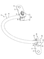
- FIG. Plan view showing the fixing structure of the multi-core cable
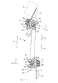
- Bottom view showing multi-core cable fixing structure
- FIG. 1 which shows the fixation structure of a multi-core cable Sectional view taken along line VV in FIG.
- Front view showing clip Side view showing the penetration part in a state of penetrating into the long hole of the bracket
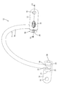
- the front view which shows the fixation structure of the multi-core cable which concerns on Embodiment 2.
- the present embodiment is a fixing structure 12 for a multicore cable 11 for fixing a multicore cable 11 (an example of a conductive member) to a vehicle body 10 of a vehicle.
- the fixing structure 12 of the multi-core cable 11 according to the present embodiment can be used when the multi-core cable 11 is bent in a narrow space, for example, inside a tire house of a vehicle. .
- Bracket 13 As shown in FIG. 3, a bracket 13 is fixed to the vehicle body 10 by bolts 14.
- the bracket 13 is formed by pressing a metal plate material into a predetermined shape.
- the bracket 13 has a horizontally long track shape.
- a round hole 15 is formed in a position near one end of the bracket 13, and a long hole 16 extending in the same direction as the direction in which the bracket 13 extends is formed in a position near the other end. Yes.
- a bolt 14 is inserted into the round hole 15 and is screwed into a bolt hole (not shown) provided in the vehicle body 10. Thereby, the bracket 13 is fixed to the vehicle body 10. On the other hand, a penetration portion 17 to be described later is inserted into the long hole 16.
- the multi-core cable 11 is formed by surrounding the outer periphery of a plurality (four in this embodiment) of electric wires 18 with a sheath 19.
- the four electric wires 18 include two power lines 18A having a relatively large diameter and two signal lines 18B having a diameter smaller than that of the power line 18A.
- the power line 18 ⁇ / b> A and the signal line 18 ⁇ / b> B are described together, they are described as the electric wires 18.
- the sheath 19 is made of an insulating synthetic resin and has a cylindrical shape. Paper, synthetic resin films, natural fibers, synthetic fibers, synthetic resin inclusions, or the like may be disposed between the sheath 19 and the electric wires 18, or nothing is disposed. It is good also as a structure. In the present embodiment, nothing is arranged between the sheath 19 and the electric wire 18.
- Clip 20 A clip 20 is fitted on the outer surface of the sheath 19.
- the clip 20 is made of an insulating synthetic resin.
- the clip 20 includes a grip portion 21 that grips the multicore cable 11 and a penetration portion 17 that penetrates into the long hole 16 of the bracket 13.
- the grip portion 21 includes a base portion 22 and two arm portions 23 extending from the base portion 22.
- the gripping part 21 is substantially C-shaped when viewed from the side.
- An opening 32 is provided between the two arm portions 23.
- a plurality of lightening portions 24 are formed in the grip portion 21 so as to be recessed from the surface of the grip portion 21. These thinned portions 24 reduce the mass of the clip 20 and suppress the deformation of the clip 20 after molding.
- the two arm portions 23 are elastically deformable in the expanding direction.
- One of the two arm portions 23 is formed with an elastic piece 25 that is folded back and extends from the tip toward the base portion 22.
- the elastic piece 25 has a thin plate shape and is formed to be more easily elastically deformed than the arm portion 23.
- the elastic piece 25 can be elastically deformed in the same direction as the arm portion 23 is elastically deformed.
- an abutting portion 26 that abuts on the outer surface of the sheath 19 of the multicore cable 11 is formed.
- the distal end surface of the contact portion 26 has a shape that follows the outer surface of the sheath 19 and forms a part of an arc.
- the accommodating space 27 is formed in a shape that follows the outer shape of the sheath 19 of the multicore cable 11 and constitutes a part of an arc.
- the outer surface of the arm portion 23 provided with the elastic piece 25 is brought into contact with the bracket 13 to prevent the clip 20 from rotating relative to the bracket 13.
- a rotation stopper 28 is formed.
- the anti-rotation portion 28 protrudes in an L-shaped shape from the outer surface of the arm portion 23 when viewed from the side.
- the distal end portion of the rotation preventing portion 28 extends along the direction from the grip portion 21 toward the penetration portion 17 and extends to the penetration portion 17 side from the base portion 22.
- the penetrating portion 17 has a shaft portion 29 protruding from the base portion 22 and a plurality (six in this embodiment) retaining portions 30 extending so as to be folded back from the tip of the shaft portion 29.
- the outer shape of the shaft portion 29 is formed smaller than the hole edge of the long hole 16 of the bracket 13 and is formed so as to be able to penetrate into the long hole 16.
- the retaining portion 30 has a plate shape extending from the distal end of the shaft portion 29 toward the base portion 22 side.
- the retaining portion 30 is formed to be elastically deformable in the radial direction of the long hole 16.
- a locking projection 31 that protrudes outward in the radial direction of the long hole 16 is formed at the tip of the retaining portion 30. The locking projection 31 is locked to the edge of the long hole 16 so that the clip 20 is prevented from coming off the bracket 13.
- the multicore cable 11 is bent.
- the multi-core cable 11 bent in this way tends to return and deform.
- the restoring force of the multicore cable 11 acts on the clip 20.
- the direction of the restoring force is a direction in which the bent multicore cable 11 expands as shown by an arrow A in FIGS. 2 and 3. For this reason, if the opening direction of the opening 32 of the clip 20 faces the direction indicated by the arrow A, the multi-core cable 11 may be disconnected from between the two arm portions 23.
- the opening directions of the opening portions 32 of the two clips 20 are each directed in a direction intersecting with the direction in which the restoring force of the multicore cable 11 acts. Thereby, one of the two arm portions 23 receives the force that the cable is restored and tries to expand. Thereby, the multi-core cable 11 is fixed by the two clips 20.
- the fixing method of the multicore cable 11 is not limited to the following procedure.
- the penetration part 17 of the clip 20 is penetrated into the long hole 16 of the bracket 13. Then, the retaining portion 30 comes into contact with the edge of the long hole 16 and is elastically deformed in the direction of diameter reduction. Further, when the penetrating portion 17 is inserted into the long hole 16, the retaining portion 30 is restored and deformed, and the locking projection 31 abuts against the edge of the long hole 16, so that the clip 20 is retained from the bracket 13. Fixed in state.
- the clip 20 is fixed to the bracket 13 in a state of being prevented from rotating by the rotation preventing portion 28 of the clip 20 coming into contact with the side edge of the bracket 13.
- the bolt 13 is inserted into the round hole 15 of the bracket 13 and screwed into the bolt hole of the vehicle body 10, thereby fixing the bracket 13 to the vehicle body 10.
- the multi-core cable 11 is fitted into the opening 32 of the grip portion 21 of the clip 20.
- the two arm portions 23 are elastically deformed in the expanding direction by contacting the sheath 19 of the multicore cable 11.
- the elastic piece 25 is elastically deformed.
- the multi-core cable 11 is accommodated in a storage space 27 formed inside the grip portion 21.
- the elastic piece 25 is restored and deformed, and comes into contact with the sheath 19 of the multicore cable 11 from the outside in the radial direction of the multicore cable 11. Thereby, it is suppressed that the multi-core cable 11 comes off from the opening part 32 of the holding part 21.
- the fixing structure 12 of the multicore cable 11 includes at least one electric wire 18 and has a multicore cable 11 fixed in a bent shape and an opening 32 into which the multicore cable 11 can be inserted.
- a plurality of clips 20 provided with a gripping portion 21, the gripping portion 21 being externally fitted to the multicore cable 11, and a bracket 13 attached in a state where the relative positions of the plurality of clips 20 are fixed.
- the plurality of clips 20 are attached to the bracket 13 in a state in which the opening direction of the opening 32 faces the direction intersecting the direction in which the restoring force of the bent multicore cable 11 acts.
- the gripping portion 21 can reliably receive the restoring force of the multicore cable 11. .
- the multi-core cable 11 can be fixed in a bent state by the clip 20 made of a synthetic resin material.
- the clip 20 made of a synthetic resin material.
- the conductive member according to the present embodiment is the multi-core cable 11 in which the periphery of the plurality of electric wires 18 is surrounded by the sheath 19.
- the multi-core cable 11 includes a plurality of electric wires 18, the restoring force tends to increase. For this reason, the technique disclosed in this specification can be suitably applied to the multicore cable 11 and can be reliably fixed in a state in which the multicore cable 11 is bent.
- the clip 20 is attached to the metal bracket 13. Thereby, the relative position of several clips 20 can be hold
- one of the clip 20 and the bracket 13 is prevented from rotating relative to the clip 20 and the bracket 13 by abutting against the other of the clip 20 and the bracket 13.
- a portion 28 is provided.
- the multicore cable 11 is fixed by three clips 40A and 40B40C while being bent in an S shape.
- the portion bent in a convex shape located on the left side in FIG. 8 applies a restoring force in the direction indicated by the arrow P.
- the downwardly bent portion located on the right side in FIG. 12 applies a restoring force in the direction indicated by the arrow Q.
- the grip portion 21 of the clip 40A located at the left end is opened on the front side in the direction penetrating the paper surface.
- the grip portion 21 of the clip 40B located at the center is also opened on the near side in the direction penetrating the paper surface.
- the gripping portion 21 of the clip 40C located at the right end is open on the far side in the direction penetrating the paper surface.
- the opening portions 32 of the grip portion 21 of the clip 40A at the left end of FIG. 8 and the grip portion 21 of the clip 40B at the center are opened in the same direction.
- the angle formed by the opening direction of the opening 32 of one clip 40B and the opening direction of the opening 32 of the other clip 40C is 180 °. It is.
- the restoring force of the multicore cable 11 can be reliably received by the grip portion 21, so that the multicore cable 11 can be reliably fixed in a bent state.
- the technology disclosed in the present specification is not limited to the embodiments described with reference to the above description and drawings, and for example, the following embodiments are also included in the technical scope of the technology disclosed in the present specification.
- the angle formed by the opening direction of the opening 32 of one clip 20 and the opening direction of the opening 32 of the other clip 20 may be a direction that intersects the direction in which the restoring force of the bent conductive member acts. For example, an arbitrary angle may be formed.
- the conductive member according to the present embodiment is the multicore cable 11 in which the periphery of the plurality of electric wires 18 is surrounded by the sheath 19, but is not limited thereto, and the electric wire is formed by covering the periphery of the core wire with an insulating coating. It is good.
- the core wire may be a stranded wire in which a plurality of fine metal wires are twisted together, or may be a so-called single core wire made of a rod-shaped metal.
- the multi-core cable 11 has the four electric wires 18, but the multi-core cable 11 is not limited to this, and the multi-core cable 11 has two, three, or a plurality of five or more. It is good also as a structure which has the electric wire 18.
- the attachment member is the metal bracket 13, but is not limited thereto, and the attachment member may be the vehicle body 10 of the vehicle. That is, the clip 20 may be directly attached to the vehicle body 10 of the vehicle.
- the bracket 13 may be made of a synthetic resin, and an arbitrary material can be appropriately selected as necessary.
- the anti-rotation portion 28 is configured to be provided on the clip 20, but the present invention is not limited thereto, and the anti-rotation portion 28 may be configured to be provided on the bracket 13 or the clip. It is good also as a structure provided in both 20 and the bracket 13. FIG. Further, the rotation stopper 28 may be omitted.
- Multi-core cable 12 Fixing structure of multi-core cable 13: Bracket 18: Electric wire 18A: Power line 18B: Signal line 19: Sheath 20: Clip 21: Holding part 28: Non-rotating part
Landscapes
- Engineering & Computer Science (AREA)
- General Engineering & Computer Science (AREA)
- Mechanical Engineering (AREA)
- Architecture (AREA)
- Civil Engineering (AREA)
- Structural Engineering (AREA)
- Clamps And Clips (AREA)
- Supports For Pipes And Cables (AREA)
- Connection Of Plates (AREA)
- Installation Of Indoor Wiring (AREA)
Abstract
多芯ケーブル11の固定構造12は、少なくとも1つの電線18を含むと共に、屈曲した形状で固定された多芯ケーブル11と、多芯ケーブル11が挿入可能な開口部32を有する把持部21を備え、把持部21が多芯ケーブル11に外嵌されている複数のクリップ20と、複数のクリップ20同士の相対的位置が固定された状態で取り付けられているブラケット13と、を備え、複数のクリップ20は、開口部32の開口方向Cが、屈曲した多芯ケーブル11の復元力が作用する方向と交差する方向を向いた状態で、ブラケット13に取り付けられている。
Description
本明細書に開示された技術は、導電部材の固定構造に関する。
従来、ワイヤーハーネス等の導電部材を固定する構造として、特許文献1に記載のものが知られている。このものは、バネ性を有する金属板からなり、両側平板部の一端を連結する円弧部でワイヤハーネスを外嵌し、上記両側平板部の先端側にボルト穴を備え、被固定材から突設させたブラケット上に上記両側平板部を重ねて搭載し、これらのボルト穴と上記ブラケットに設けたボルト穴とを連通させてボルトとナットとで締結してワイヤハーネスを被固定材に沿って配索固定するワイヤハーネス固定用クリップであって、上記両側平板部のいずれか一方の先端を屈曲させて平板形状のストッパー部を設け、該ストッパー部を上記固定材に当接させて上記ボルト・ナットの締結時に回り止めされる構成としている。
上記のクリップが、車両の外部等、クリップが腐食する恐れがある箇所で使用される場合には、クリップには防食用の塗装が施される。
しかしながら、上記の構成によると、バネ性を有する金属板により構成されたワイヤーハーネス固定用のクリップは、ワイヤーハーネスにそって曲げ加工されるようになっている。このため、安価な塗料を用いた場合には、クリップを変形させたときに塗膜が剥がれることが懸念される。
塗膜が剥がれることを抑制しようとすると、高価な塗料を用いる必要があるため、製造コストが上昇するという問題があった。
本明細書に開示された技術は上記のような事情に基づいて完成されたものであって、製造コストが低減された、導電部材の固定構造を提供することを目的とする。
本明細書に開示された技術は、導電部材の固定構造であって、少なくとも1つの電線を含むと共に、屈曲した形状で固定された導電部材と、前記導電部材が挿入可能な開口部を有する把持部を備え、前記把持部が前記導電部材に外嵌されている複数のクリップと、前記複数のクリップ同士の相対的位置が固定された状態で取り付けられている取り付け部材と、を備え、前記複数のクリップは、前記開口部の開口方向が、屈曲した前記導電部材の復元力が作用する方向と交差する方向を向いた状態で、前記取り付け部に取り付けられている。
上記の構成によれば、屈曲した導電部材は復帰変形しようとするので、クリップの把持部に対して、導電部材から復元力が作用する。その際、把持部の開口方向は、導電部材の復元力の作用する方向と交差する方向を向いているので、把持部によって導電部材の復元力を確実に受けることができる。これにより、合成樹脂材からなるクリップによって、導電部材を屈曲した状態で固定することができる。この結果、金属部材を塑性変形させる必要がないので、金属部材に特殊な表面処理を施す必要がなくなる。この結果、製造コストを低減させることができる。
本明細書に開示された技術の実施態様としては以下の態様が好ましい。
前記導電部材は、複数の電線の周囲がシースによって包囲された多芯ケーブルであってもよい。
多芯ケーブルは複数の電線を含むので、復元力が大きくなる傾向にある。このため、本明細書に記載された技術を適用することにより、多芯ケーブルを屈曲した状態で、確実に固定することができる。
取り付け部材は金属製のブラケットであってもよい。
上記の構成によれば、複数のクリップ同士の相対的位置を確実に保持することができる。
前記クリップ及び前記取り付け部材の一方には、前記クリップ及び前記取り付け部材の他方と当接することにより、前記クリップと前記取り付け部材とが相対的に回転することが抑制される回り止め部が設けられていることが好ましい。
上記の構成によれば、クリップと取り付け部材とが相対的に回転することが抑制される。これにより、クリップの開口部の開口方向が変化することを抑制することができるので、クリップによって導電部材を確実に保持することができる。
前記複数のクリップのうち、一のクリップの開口部の開口方向と、他のクリップの開口部の開口方向と、のなす角度が180°であることが好ましい。
上記の構成によれば、導電部材の復元力を把持部によって確実に受けることができるので、導電部材を、屈曲した状態で確実に固定することができる。
本明細書に開示された技術によれば、製造コストが低減された、導電部材の固定構造を得ることができる。
<実施形態1>
本明細書に開示された技術の実施形態1を、図1ないし図7を参照しつつ説明する。本実施形態は、車両の車体10に、多芯ケーブル11(導電部材の一例)を固定するための、多芯ケーブル11の固定構造12である。本実施形態に係る多芯ケーブル11の固定構造12は、例えば、車両のタイヤハウスの内側のように、狭い空間内に多芯ケーブル11を屈曲させた状態で配索する場合に用いることができる。
本明細書に開示された技術の実施形態1を、図1ないし図7を参照しつつ説明する。本実施形態は、車両の車体10に、多芯ケーブル11(導電部材の一例)を固定するための、多芯ケーブル11の固定構造12である。本実施形態に係る多芯ケーブル11の固定構造12は、例えば、車両のタイヤハウスの内側のように、狭い空間内に多芯ケーブル11を屈曲させた状態で配索する場合に用いることができる。
1.ブラケット13
図3に示すように、車体10には、ブラケット13が、ボルト14により固定されるようになっている。ブラケット13は金属板材を所定の形状にプレス加工してなる。本実施形態では、ブラケット13は横長のトラック形状をなしている。ブラケット13の一方の端部寄りの位置には丸孔15が貫通形成されており、他方の端部寄りの位置には、ブラケット13が細長く延びる方向と同じ方向に延びる長孔16が形成されている。
図3に示すように、車体10には、ブラケット13が、ボルト14により固定されるようになっている。ブラケット13は金属板材を所定の形状にプレス加工してなる。本実施形態では、ブラケット13は横長のトラック形状をなしている。ブラケット13の一方の端部寄りの位置には丸孔15が貫通形成されており、他方の端部寄りの位置には、ブラケット13が細長く延びる方向と同じ方向に延びる長孔16が形成されている。
丸孔15には、ボルト14が挿通されて、車体10に設けられたボルト孔(図示せず)に螺合されるようになっている。これにより、ブラケット13が車体10に固定されるようになっている。一方、長孔16には、後述する貫入部17が貫入されるようになっている。
2.多芯ケーブル11
多芯ケーブル11は、複数(本実施形態では4つ)の電線18の外周をシース19で包囲してなる。4つの電線18は、比較的に直径の大きな2つの電力線18Aと、電力線18Aに比べて直径の小さな2つの信号線18Bと、からなる。以下の説明において、電力線18Aと信号線18Bとをまとめて説明する際には、電線18として説明する。
多芯ケーブル11は、複数(本実施形態では4つ)の電線18の外周をシース19で包囲してなる。4つの電線18は、比較的に直径の大きな2つの電力線18Aと、電力線18Aに比べて直径の小さな2つの信号線18Bと、からなる。以下の説明において、電力線18Aと信号線18Bとをまとめて説明する際には、電線18として説明する。
シース19は絶縁性の合成樹脂からなり、筒状をなしている。シース19と、電線18との間には、紙、合成樹脂製のフィルム、天然繊維、合成繊維、合成樹脂製の介在物等が配されていてもよいし、また、何も配されていない構成としてもよい。本実施形態では、シース19と電線18との間には何も配されていない。
3.クリップ20
シース19の外面には、クリップ20が外嵌されている。クリップ20は、絶縁性の合成樹脂からなる。クリップ20は、多芯ケーブル11を把持する把持部21と、ブラケット13の長孔16に貫入される貫入部17と、を備える。
シース19の外面には、クリップ20が外嵌されている。クリップ20は、絶縁性の合成樹脂からなる。クリップ20は、多芯ケーブル11を把持する把持部21と、ブラケット13の長孔16に貫入される貫入部17と、を備える。
把持部21は、基部22と、基部22から延びる2本のアーム部23と、を備える。把持部21は、側方から見て、略C字状をなしている。2本のアーム部23の間は開口部32とされる。把持部21には、複数の肉抜き部24が、把持部21の表面から陥没して形成されている。これらの肉抜き部24により、クリップ20の質量が軽減されるとともに、成型後にクリップ20が変形することが抑制されるようになっている。
2本のアーム部23は拡開方向に弾性変形可能になっている。2本のアーム部23のうち、一方がアーム部23には、先端から基部22に向かって折り返して延びる、弾性片25が形成されている。弾性片25は、薄い板状をなしており、アーム部23よりも弾性変形しやすいように形成されている。弾性片25は、アーム部23が弾性変形する方向と同じ方向に弾性変形可能とされている。
弾性片25の先端には、多芯ケーブル11のシース19の外面と当接する当接部26が形成されている。当接部26の先端面は、シース19の外面に倣った形状であって、円弧の一部を構成している。
2本のアーム部23と基部22との間には、多芯ケーブル11が収容される収容空間27が設けられている。収容空間27は、多芯ケーブル11のシース19の外形状に倣った形状に形成されており、円弧の一部を構成している。
2本のアーム部23のうち、弾性片25が設けられたアーム部23の外面には、ブラケット13と当接することにより、クリップ20がブラケット13に対して相対的に回動することを抑制する、回り止め部28が形成されている。
回り止め部28は、側方から見て、アーム部23の外面からL字状に曲がった形状で突出している。回り止め部28の先端部は、把持部21から貫入部17に向かう方向に沿って延びており、基部22よりも貫入部17側に延出されている。
貫入部17は、基部22から突出する軸部29と、軸部29の先端から折り返すように延びる複数(本実施形態では6つ)の抜け止め部30と、を有する。軸部29の外形状は、ブラケット13の長孔16の孔縁よりも小さく形成されており、長孔16に貫入可能に形成されている。
抜け止め部30は、軸部29の先端から基部22側に向かって延びる板状をなしている。抜け止め部30は、長孔16の径方向に弾性変形可能に形成されている。抜け止め部30の先端には、長孔16の径方向の外方に突出する係止突起31が形成されている。この係止突起31が、長孔16の口縁部に係止することにより、クリップ20がブラケット13から抜けることが抑制されるようになっている。
クリップ20の貫入部17が、ブラケット13の長孔16に貫入された状態で、クリップ20の回り止め部28の先端部は、ブラケット13の側縁の近傍に位置するようになっている。これにより、クリップ20の貫入部17がブラケット13の長孔16内で回転しようとしても、回り止め部28の先端部が、ブラケット13の側縁と当接することにより、クリップ20がブラケット13に対して相対的に回転することが抑制されるようになっている。回り止め部28の先端部と、ブラケット13の側縁とは面接触するようになっている。これにより、クリップ20とブラケット13とは確実に回り止めされるようになっている。
4.多芯ケーブル11の固定構造
図1に示すように、多芯ケーブル11は略U字状に屈曲した状態で固定されている。多芯ケーブル11のシース19には2つのクリップ20が外嵌されている。多芯ケーブル11のうち、クリップ20よりも下方に延びる部分については省略している。
図1に示すように、多芯ケーブル11は略U字状に屈曲した状態で固定されている。多芯ケーブル11のシース19には2つのクリップ20が外嵌されている。多芯ケーブル11のうち、クリップ20よりも下方に延びる部分については省略している。
図2及び図3に示すように、多芯ケーブル11は屈曲されている。このように屈曲された多芯ケーブル11は、復帰変形しようとする。これにより、クリップ20に対しては、多芯ケーブル11の復元力が作用する。復元力の方向は、図2及び図3において、矢線Aで示すように、屈曲された多芯ケーブル11が拡開する方向となっている。このため、仮に、クリップ20の開口部32の開口方向が矢線Aで示す方向を向いていた場合、2本のアーム部23の間から、多芯ケーブル11が外れてしまうおそれがある。
一方、仮に、クリップ20の開口部32の開口方向が、矢線Bで示すように、内向きであった場合、今度は、多芯ケーブル11のシース19が2本のアーム部23の間を、下方に滑り落ちてしまうおそれがある。
本実施形態においては、2つのクリップ20の開口部32の開口方向は、それぞれ、多芯ケーブル11の復元力の作用する方向と交差する方向を向いている。これにより、ケーブルが復帰して拡開しようとする力を、2つのアーム部23の一方が、確実に受けるようになっている。これにより、2つのクリップ20によって、多芯ケーブル11が固定されるようになっている。
5.多芯ケーブル11の固定方法
続いて、多芯ケーブル11の固定方法の一例について以下に説明する。多芯ケーブル11の固定方法は下記の手順に限定されない。
続いて、多芯ケーブル11の固定方法の一例について以下に説明する。多芯ケーブル11の固定方法は下記の手順に限定されない。
まず、クリップ20の貫入部17を、ブラケット13の長孔16に貫入させる。すると、抜け止め部30が長孔16の口縁部に当接することにより、縮径方向に弾性変形する。更に貫入部17を長孔16内に挿入すると、抜け止め部30が復帰変形し、係止突起31が長孔16の口縁部に当接することにより、クリップ20がブラケット13から抜け止めされた状態で固定される。
更に、クリップ20の回り止め部28がブラケット13の側縁に当接することにより、クリップ20は、ブラケット13に対して、回り止めされた状態で固定される。
続いて、ブラケット13の丸孔15内に、ボルト14を挿通し、車体10のボルト孔に螺合することにより、ブラケット13を車体10に固定する。
続いて、多芯ケーブル11を、クリップ20の把持部21の開口部32内に嵌め入れる。2つのアーム部23は、多芯ケーブル11のシース19と当接することにより、拡開方向に弾性変形する。更に多芯ケーブル11を把持部21の奥方に押し込むと、弾性片25が弾性変形する。更に多芯ケーブル11を把持部21の奥方に押し込むと、把持部21の内側に形成された収容空間27内に多芯ケーブル11が収容される。すると、弾性片25が復帰変形し、多芯ケーブル11のシース19に、多芯ケーブル11の径方向の外側から当接する。これにより、多芯ケーブル11が把持部21の開口部32から外れることが抑制される。
6.実施形態の作用、効果
続いて、本実施形態の作用、効果について説明する。本実施形態に係る多芯ケーブル11の固定構造12は、少なくとも1つの電線18を含むと共に、屈曲した形状で固定された多芯ケーブル11と、多芯ケーブル11が挿入可能な開口部32を有する把持部21を備え、把持部21が多芯ケーブル11に外嵌されている複数のクリップ20と、複数のクリップ20同士の相対的位置が固定された状態で取り付けられているブラケット13と、を備え、複数のクリップ20は、開口部32の開口する方向が、屈曲した多芯ケーブル11の復元力が作用する方向と交差する方向を向いた状態で、ブラケット13に取り付けられている。
続いて、本実施形態の作用、効果について説明する。本実施形態に係る多芯ケーブル11の固定構造12は、少なくとも1つの電線18を含むと共に、屈曲した形状で固定された多芯ケーブル11と、多芯ケーブル11が挿入可能な開口部32を有する把持部21を備え、把持部21が多芯ケーブル11に外嵌されている複数のクリップ20と、複数のクリップ20同士の相対的位置が固定された状態で取り付けられているブラケット13と、を備え、複数のクリップ20は、開口部32の開口する方向が、屈曲した多芯ケーブル11の復元力が作用する方向と交差する方向を向いた状態で、ブラケット13に取り付けられている。
上記の構成によれば、屈曲した多芯ケーブル11は復帰変形しようとするので、クリップ20の把持部21に対して、多芯ケーブル11から復元力が作用する。その際、把持部21の開口方向は、多芯ケーブル11の復元力の作用する方向と交差する方向を向いているので、把持部21によって多芯ケーブル11の復元力を確実に受けることができる。これにより、合成樹脂材からなるクリップ20によって、多芯ケーブル11を屈曲した状態で固定することができる。この結果、金属部材を塑性変形させる必要がないので、金属部材に特殊な表面処理を施す必要がなくなる。この結果、製造コストを低減させることができる。
また、本実施形態に係る導電部材は、複数の電線18の周囲がシース19によって包囲された多芯ケーブル11である。
多芯ケーブル11は複数の電線18を含むので、復元力が大きくなる傾向にある。このため、本明細書に開示された技術は多芯ケーブル11に好適に適用することが可能であって、多芯ケーブル11を屈曲した状態で、確実に固定することができる。
また、本実施形態においては、クリップ20は金属製のブラケット13に取り付けられている。これにより、複数のクリップ20同士の相対的位置を確実に保持することができる。
また、本実施形態においては、クリップ20及びブラケット13の一方には、クリップ20及びブラケット13の他方と当接することにより、クリップ20とブラケット13とが相対的に回転することが抑制される回り止め部28が設けられている。
上記の構成によれば、クリップ20とブラケット13とが相対的に回転することが抑制される。これにより、クリップ20の把持部21の開口部32の開口方向が変化することを抑制することができるので、クリップ20によって多芯ケーブル11を確実に保持することができる。
<実施形態2>
次に、本明細書に開示された技術の実施形態2を図8を参照しつつ説明する。本実施形態に係る多芯ケーブル11の固定構造41においては、多芯ケーブル11は、S字状に屈曲した状態で、3つのクリップ40A,40B40Cによって固定されている。図8において左側に位置する、上方に凸状に屈曲した部分は、矢線Pで示す方向に復元力を作用させる。一方、図12において右側に位置する、下方に屈曲した部分は、矢線Qで示す方向に復元力を作用させる。
次に、本明細書に開示された技術の実施形態2を図8を参照しつつ説明する。本実施形態に係る多芯ケーブル11の固定構造41においては、多芯ケーブル11は、S字状に屈曲した状態で、3つのクリップ40A,40B40Cによって固定されている。図8において左側に位置する、上方に凸状に屈曲した部分は、矢線Pで示す方向に復元力を作用させる。一方、図12において右側に位置する、下方に屈曲した部分は、矢線Qで示す方向に復元力を作用させる。
3つのクリップ40A,40B,40Cのうち、左端に位置するクリップ40Aの把持部21は、紙面を貫通する方向の手前側に開口している。また、中央に位置するクリップ40Bの把持部21も、紙面を貫通する方向の手前側に開口している。一方、右端部に位置するクリップ40Cの把持部21は、紙面を貫通する方向の奥側に開口している。
本実施形態においては、図8の中央のクリップ40Bの把持部21と、右端部のクリップ40Cの把持部21とは、それぞれの開口部32の開口方向のなす角度が180°に設定されている。
また、本実施形態においては、図8の左端のクリップ40Aの把持部21と、中央のクリップ40Bの把持部21とは、それぞれの開口部32は同じ方向に開口している。
上記以外の構成については、実施形態1と略同様なので、同一部材については同一符号を付し、重複する説明を省略する。
本実施形態によれば、複数のクリップ40A,40B,40Cのうち、一のクリップ40Bの開口部32の開口方向と、他のクリップ40Cの開口部32の開口方向と、のなす角度が180°である。
上記の構成によれば、多芯ケーブル11の復元力を把持部21によって確実に受けることができるので、多芯ケーブル11を、屈曲した状態で確実に固定することができる。
<他の実施形態>
本明細書に開示された技術は上記記述及び図面によって説明した実施形態に限定されるものではなく、例えば次のような実施形態も本明細書に開示された技術の技術的範囲に含まれる。
(1)一のクリップ20の開口部32の開口方向と、他のクリップ20の開口部32の開口方向とのなす角度は、屈曲した導電部材の復元力が作用する方向と交差する方向であれば、任意の角度をなしていてもよい。
本明細書に開示された技術は上記記述及び図面によって説明した実施形態に限定されるものではなく、例えば次のような実施形態も本明細書に開示された技術の技術的範囲に含まれる。
(1)一のクリップ20の開口部32の開口方向と、他のクリップ20の開口部32の開口方向とのなす角度は、屈曲した導電部材の復元力が作用する方向と交差する方向であれば、任意の角度をなしていてもよい。
(2)本実施形態に係る導電部材は、複数の電線18の周囲がシース19によって包囲された多芯ケーブル11であったが、これに限られず、芯線の周囲を絶縁被覆で覆ってなる電線としてもよい。この芯線は、複数の金属細線が撚り合わされた撚り線でもよく、また、棒状の金属からなる、いわゆる単芯線でもよい。
(3)本実施形態によれば、多芯ケーブル11は4つの電線18を有する構成としたが、これに限られず、多芯ケーブル11は、2つ、3つ、又は5つ以上の複数の電線18を有する構成としてもよい。
(4)本実施形態によれば、取り付け部材は金属製のブラケット13であったが、これに限られず、取り付け部材は、車両の車体10であってもよい。つまり、クリップ20は車両の車体10に直接取り付けてもよい。また、ブラケット13は合成樹脂製であってもよく、必要に応じて任意の材料を適宜に選択することができる。
(5)本実施形態においては、回り止め部28は、クリップ20に設けられる構成としたが、これに限られず、回り止め部28は、ブラケット13に設けられる構成としてもよいし、また、クリップ20とブラケット13の双方に設けられる構成としてもよい。また、回り止め部28は省略してもよい。
11:多芯ケーブル
12:多芯ケーブルの固定構造
13:ブラケット
18:電線
18A:電力線
18B:信号線
19:シース
20:クリップ
21:把持部
28:回り止め部
12:多芯ケーブルの固定構造
13:ブラケット
18:電線
18A:電力線
18B:信号線
19:シース
20:クリップ
21:把持部
28:回り止め部
Claims (5)
- 少なくとも1つの電線を含むと共に、屈曲した形状で固定された導電部材と、
前記導電部材が挿入可能な開口部を有する把持部を備え、前記把持部が前記導電部材に外嵌されている複数のクリップと、
前記複数のクリップ同士の相対的位置が固定された状態で取り付けられている取り付け部材と、を備え、
前記複数のクリップは、前記開口部の開口方向が、屈曲した前記導電部材の復元力が作用する方向と交差する方向を向いた状態で、前記取り付け部に取り付けられている、導電部材の固定構造。 - 前記導電部材は、複数の電線の周囲がシースによって包囲された多芯ケーブルである、請求項1に記載の導電部材の固定構造。
- 取り付け部材は金属製のブラケットである、請求項1または請求項2に記載の導電部材の固定構造。
- 前記クリップ及び前記取り付け部材の一方には、前記クリップ及び前記取り付け部材の他方と当接することにより、前記クリップと前記取り付け部材とが相対的に回転することが抑制される回り止め部が設けられている、請求項1から請求項3のいずれか一項に記載の導電部材の固定構造。
- 前記複数のクリップのうち、一のクリップの開口部の開口方向と、他のクリップの開口部の開口方向と、のなす角度が180°である、請求項1から請求項4のいずれか一項に記載の導電部材の固定構造。
Applications Claiming Priority (2)
| Application Number | Priority Date | Filing Date | Title |
|---|---|---|---|
| JP2017052291A JP2018157681A (ja) | 2017-03-17 | 2017-03-17 | 導電部材の固定構造 |
| JP2017-052291 | 2017-03-17 |
Publications (1)
| Publication Number | Publication Date |
|---|---|
| WO2018168485A1 true WO2018168485A1 (ja) | 2018-09-20 |
Family
ID=63522089
Family Applications (1)
| Application Number | Title | Priority Date | Filing Date |
|---|---|---|---|
| PCT/JP2018/007714 Ceased WO2018168485A1 (ja) | 2017-03-17 | 2018-03-01 | 導電部材の固定構造 |
Country Status (2)
| Country | Link |
|---|---|
| JP (1) | JP2018157681A (ja) |
| WO (1) | WO2018168485A1 (ja) |
Cited By (2)
| Publication number | Priority date | Publication date | Assignee | Title |
|---|---|---|---|---|
| DE102022134198A1 (de) * | 2022-12-20 | 2024-06-20 | Karl Storz Se & Co. Kg | Ablenksteuerungsmechanismus für eine medizinische Vorrichtung, medizinische Vorrichtung, Wartungsverfahren und Verfahren zur Montage eines Ablenksteuerungsmechanismus oder einer medizinischen Vorrichtung |
| JP7552809B1 (ja) | 2023-07-31 | 2024-09-18 | いすゞ自動車株式会社 | ワイヤハーネス固定構造 |
Families Citing this family (1)
| Publication number | Priority date | Publication date | Assignee | Title |
|---|---|---|---|---|
| JP7295667B2 (ja) * | 2019-03-20 | 2023-06-21 | 古河電気工業株式会社 | 保持具及び保護カバー |
Citations (3)
| Publication number | Priority date | Publication date | Assignee | Title |
|---|---|---|---|---|
| JPS58127513A (ja) * | 1982-01-20 | 1983-07-29 | 沖電気工業株式会社 | ケ−ブルクランプ |
| JP2003259535A (ja) * | 2002-03-07 | 2003-09-12 | Yazaki Corp | フラット回路体の配索構造 |
| JP2004340309A (ja) * | 2003-05-16 | 2004-12-02 | Piolax Inc | 管・線状物固定用クリップ |
Family Cites Families (3)
| Publication number | Priority date | Publication date | Assignee | Title |
|---|---|---|---|---|
| JPS5543160U (ja) * | 1978-09-14 | 1980-03-21 | ||
| JPH01131391A (ja) * | 1987-11-17 | 1989-05-24 | Mirai Ind Co Ltd | 管又は線の固定装置 |
| JP2005188578A (ja) * | 2003-12-25 | 2005-07-14 | Nippon Pop Rivets & Fasteners Ltd | パイプ等の長尺物のクランプ |
-
2017
- 2017-03-17 JP JP2017052291A patent/JP2018157681A/ja active Pending
-
2018
- 2018-03-01 WO PCT/JP2018/007714 patent/WO2018168485A1/ja not_active Ceased
Patent Citations (3)
| Publication number | Priority date | Publication date | Assignee | Title |
|---|---|---|---|---|
| JPS58127513A (ja) * | 1982-01-20 | 1983-07-29 | 沖電気工業株式会社 | ケ−ブルクランプ |
| JP2003259535A (ja) * | 2002-03-07 | 2003-09-12 | Yazaki Corp | フラット回路体の配索構造 |
| JP2004340309A (ja) * | 2003-05-16 | 2004-12-02 | Piolax Inc | 管・線状物固定用クリップ |
Cited By (3)
| Publication number | Priority date | Publication date | Assignee | Title |
|---|---|---|---|---|
| DE102022134198A1 (de) * | 2022-12-20 | 2024-06-20 | Karl Storz Se & Co. Kg | Ablenksteuerungsmechanismus für eine medizinische Vorrichtung, medizinische Vorrichtung, Wartungsverfahren und Verfahren zur Montage eines Ablenksteuerungsmechanismus oder einer medizinischen Vorrichtung |
| JP7552809B1 (ja) | 2023-07-31 | 2024-09-18 | いすゞ自動車株式会社 | ワイヤハーネス固定構造 |
| JP2025021017A (ja) * | 2023-07-31 | 2025-02-13 | いすゞ自動車株式会社 | ワイヤハーネス固定構造 |
Also Published As
| Publication number | Publication date |
|---|---|
| JP2018157681A (ja) | 2018-10-04 |
Similar Documents
| Publication | Publication Date | Title |
|---|---|---|
| WO2018168485A1 (ja) | 導電部材の固定構造 | |
| US6244517B1 (en) | System for fixing an electric terminal connector | |
| JP2019007620A (ja) | ロボットによる設置のためのケーブルアセンブリ | |
| JP2017111873A (ja) | ワイヤハーネス | |
| EP2684258B1 (en) | An electric connector accessory and its method of assembly | |
| JP2002286014A (ja) | ネジ保持アッセンブリ,ネジ保持装置及びネジ保持方法 | |
| CA2853492C (en) | Terminal device for grounding direct current electrical component | |
| JP2015103494A (ja) | アース端子 | |
| US7955131B2 (en) | Accessory of the backshell type for connector | |
| US9306299B2 (en) | Connection terminal having superimposed flat plate shaped attaching parts | |
| JP3832114B2 (ja) | 碍子、中心導体及びそれらを使用した口出部の接続構造体 | |
| US5634827A (en) | Electrical connection device for conducting cable shields and methods of employing it | |
| WO2019176539A1 (ja) | 接続端子及び端子接続体 | |
| CN110962767A (zh) | 配线构件 | |
| JP2016149278A (ja) | ワイヤーハーネス | |
| US20220158369A1 (en) | Grounding clamp with lateral anti-twist protection | |
| JP7798349B2 (ja) | 固定具 | |
| WO2024247562A1 (ja) | ケーブル固定装置 | |
| JP6156265B2 (ja) | アース端子 | |
| JP2025018142A (ja) | クリップの回転抑制部材 | |
| JP6078293B2 (ja) | 電線の接続端子 | |
| JP6332085B2 (ja) | 金属製結束バンドを用いたアース接続構造 | |
| JP3296662B2 (ja) | 仮止め機構付回転コネクタ | |
| JP2017139862A (ja) | ワイヤハーネス | |
| US8517778B2 (en) | Cable terminal having a fixing element with a locking teeth engaging a locking edge to prevent a release of the fixing element |
Legal Events
| Date | Code | Title | Description |
|---|---|---|---|
| 121 | Ep: the epo has been informed by wipo that ep was designated in this application |
Ref document number: 18767033 Country of ref document: EP Kind code of ref document: A1 |
|
| NENP | Non-entry into the national phase |
Ref country code: DE |
|
| 122 | Ep: pct application non-entry in european phase |
Ref document number: 18767033 Country of ref document: EP Kind code of ref document: A1 |