WO2018168147A1 - トラクタ - Google Patents
トラクタ Download PDFInfo
- Publication number
- WO2018168147A1 WO2018168147A1 PCT/JP2017/046137 JP2017046137W WO2018168147A1 WO 2018168147 A1 WO2018168147 A1 WO 2018168147A1 JP 2017046137 W JP2017046137 W JP 2017046137W WO 2018168147 A1 WO2018168147 A1 WO 2018168147A1
- Authority
- WO
- WIPO (PCT)
- Prior art keywords
- swing
- load detection
- load
- detection member
- swinging
- Prior art date
- Legal status (The legal status is an assumption and is not a legal conclusion. Google has not performed a legal analysis and makes no representation as to the accuracy of the status listed.)
- Ceased
Links
Images







Classifications
-
- A—HUMAN NECESSITIES
- A01—AGRICULTURE; FORESTRY; ANIMAL HUSBANDRY; HUNTING; TRAPPING; FISHING
- A01B—SOIL WORKING IN AGRICULTURE OR FORESTRY; PARTS, DETAILS, OR ACCESSORIES OF AGRICULTURAL MACHINES OR IMPLEMENTS, IN GENERAL
- A01B63/00—Lifting or adjusting devices or arrangements for agricultural machines or implements
- A01B63/02—Lifting or adjusting devices or arrangements for agricultural machines or implements for implements mounted on tractors
- A01B63/10—Lifting or adjusting devices or arrangements for agricultural machines or implements for implements mounted on tractors operated by hydraulic or pneumatic means
- A01B63/111—Lifting or adjusting devices or arrangements for agricultural machines or implements for implements mounted on tractors operated by hydraulic or pneumatic means regulating working depth of implements
- A01B63/112—Lifting or adjusting devices or arrangements for agricultural machines or implements for implements mounted on tractors operated by hydraulic or pneumatic means regulating working depth of implements to control draught load, i.e. tractive force
Definitions
- the present invention includes a three-point link mechanism that is connected to a rear portion of a vehicle body so as to be able to swing up and down and that can be attached to a working device including a tilling device, and a hydraulic lift drive that drives the three-point link mechanism up and down A unit and a mechanical linkage unit for automatic raising / lowering that converts a change amount of the traction load into a raising / lowering operation amount and transmits it to the raising / lowering driving unit during a tilling operation in which the tilling device is attached to the three-point link mechanism.
- a three-point link mechanism that is connected to a rear portion of a vehicle body so as to be able to swing up and down and that can be attached to a working device including a tilling device
- a hydraulic lift drive that drives the three-point link mechanism up and down
- a unit and a mechanical linkage unit for automatic raising / lowering that converts a change amount of the traction load into a raising / lowering operation amount and transmits it to
- the tractor capable of draft control includes a draft adjustment lever for setting tillage depth, a link mechanism (such as a cylinder shaft and arm) that links the spool of the control valve to the draft adjustment lever, and a load detection that swings back and forth according to the traction load.
- a link mechanism such as a cylinder shaft and arm
- a load detection that swings back and forth according to the traction load.
- the tillage device increases at a standard speed based on the increase of the traction load.
- the increase in the traction load cannot be suitably suppressed, and there is a risk of causing an engine stall due to the increase in the traction load.
- the tillage device By switching to, the tillage device can be raised and lowered according to the traction load at a high speed suitable for this field. As a result, it is possible to avoid an engine stall due to an increase in the traction load in both the field where the traction load is difficult to change rapidly and the field where the traction load easily changes rapidly.
- JP 2006-109802 A Japanese Patent Application No. 2016-182005
- a load detecting member that swings back and forth in accordance with a traction load transmitted through a top link of a three-point link mechanism to a mechanical linkage unit including a change amount conversion mechanism, a load detection member A swinging member supported so as to be swingable, a holding mechanism that biases the swinging member to a predetermined position with respect to the load detection member, a receiving member that can be repositioned between an operating position and a retracted position with respect to the swinging member, and And a link mechanism for interlockingly connecting the swinging member and the elevating drive unit.
- the load detecting member and the swinging member swing together by the action of the holding mechanism because the receiving member is located at the retracted position.
- the amount of change in the traction load is not amplified and transmitted to the lifting drive unit as the lifting operation amount, and as a result, the tillage device moves up and down at a standard speed.
- the receiving member is positioned at the operating position, so that the load detecting member swings in the upward direction of the traction load so that the holding mechanism resists the action.
- the load detection member and the swing member are relatively swung relative to each other.
- the amount of change in the traction load is amplified and transmitted to the lift drive unit as the lift operation amount, and as a result, the tillage device moves up and down at a high speed.
- a tractor according to the present invention is connected to a rear portion of a vehicle body so as to be able to swing up and down, and allows a work device including a tilling device to be attached, and a hydraulic type that drives the three-point link mechanism up and down.
- Elevating drive unit and a mechanical linkage unit for automatic elevating when converting the change amount of the traction load into the elevating operation amount and transmitting it to the elevating drive unit at the time of tilling work where the tillage device is attached to the three-point link mechanism
- the mechanical linkage unit includes a load detection member that swings back and forth in accordance with a traction load transmitted through the top link of the three-point link mechanism, and an urging force that oscillates the load detection member in the direction of decreasing the traction load.
- An urging mechanism a swinging member supported by the load detection member so as to be swingable, a regulation mechanism for restricting swinging of the swinging member with respect to the load detection member, the swinging member, and the elevating drive unit,
- a link mechanism that interlocks and The restriction mechanism includes a receiving member that swings integrally with the load detection member, and a biasing unit that swings and biases the swinging member in a direction in which the swinging member is pressed against the receiving member.
- the catcher swings integrally with the load detection member, and the swing member is attached. It is held in a state of being pressed against the receiving member by the action of the biasing unit.
- the urging unit includes a first urging mechanism that is installed from the load detection member to the oscillating member or the link mechanism and suppresses oscillating of the oscillating member relative to the load detecting member, and a vehicle body fixing member.
- a second urging mechanism that is installed on the swing member or the link mechanism and suppresses the swing of the load detection member and the swing member in the direction of increasing the traction load.
- the first biasing mechanism swings relative to the load detection member regardless of whether the load detection member swings back and forth according to the traction load.
- the force for suppressing the swing of the member is constant.
- the first biasing mechanism is configured such that the swing of the swing member with respect to the load detection member increases as the swing member swings with respect to the load detection member. The power to suppress movement is increased.
- the second urging mechanism is configured so that the load detection member and the swing member swing together and the load detection member and the swing member swing relative to each other.
- the force for suppressing the swinging of the load detection member and the oscillating member in the traction load increasing direction increases.
- the second biasing mechanism swings relative to the load detection member as the load detection member swings greatly in the upward direction of the traction load. The greater the swing of the moving member, the greater the force that prevents the load detection member and the swing member from swinging in the direction of increasing the traction load.
- the second biasing mechanism is more effective when the load detection member and the swing member swing relative to each other than when the load detection member and the swing member swing together.
- fluctuation to the traction load raising direction of a moving member becomes large.
- the second urging mechanism is configured so that the load detection member is a traction load regardless of whether the load detection member and the swing member swing together or the load detection member and the swing member swing relative to each other.
- the greater the swing in the upward direction the greater the force that suppresses the swing of the load detection member and the swing member in the direction of increasing the traction load. It functions as a damper that attenuates the movement.
- the first urging mechanism includes a first tension spring installed from the load detection member to the swing member or the link mechanism, and a second tension spring having a smaller diameter than the first tension spring.
- the second tension spring extends from the load detection member to the swing member or the link mechanism through the inside of the first tension spring.
- the outer diameter of the first urging mechanism can be made smaller than when the first urging mechanism is constituted by a single tension spring.
- high tension necessary for the first urging mechanism can be ensured without increasing the size of the first urging mechanism, and it is easy to avoid the disadvantage that the first urging mechanism interferes with the peripheral members.
- the second urging mechanism includes a rod that is inserted and supported so as to be able to move in and out of the fixing member, and is linked to the swinging member, and a compression spring that is externally fitted to the rod.
- One end of the compression spring is applied to the fixing member, and the other end of the compression spring is supported by the rod, The support position of the other end on the rod is changeable.
- the second urging mechanism uses a compression spring
- the spring is more selective than the one using a tension spring, and the spring can be freely adjusted according to the field characteristics and regional characteristics. Easy to choose.
- biasing mechanism can be adjusted by changing the support position of the other end part of a compression spring. Therefore, for example, the urging force of the second urging mechanism is changed in accordance with the hardness of the soil in different fields depending on the region, and the possibility of chattering occurring more reliably and suitably regardless of the soil hardness of the field. Can be suppressed. Further, when the compression spring deteriorates and the restoring force decreases, it is possible to adjust the spring force to an appropriate value and prolong the use period of the compression spring.
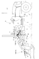
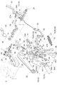
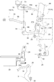
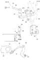
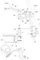
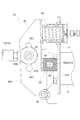
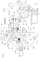
- FIG. 6 is a sectional view taken along line XI-XI in FIG. 4. It is a vertical right side view of the principal part showing the operating state of the mechanical linkage unit and the lift drive unit when the traction load does not exceed the set value in the standard conversion state of the change amount conversion mechanism. It is a vertical right side view of the principal part showing the operating state of the mechanical linkage unit and the lifting drive unit when the traction load exceeds the set value in the standard conversion state of the change amount conversion mechanism.
- the direction indicated by the arrow F in FIGS. 1 and 2 is the front side of the tractor, and the direction indicated by the arrow U is the upper side of the tractor.
- the tractor exemplified in this embodiment includes a front frame 1 disposed at the front of the vehicle body, an engine 2 connected to the rear of the front frame 1, and a lower rear end of the engine 2.
- the clutch housing 3 connected to the clutch housing 3, the intermediate frame 4 connected to the rear end portion of the clutch housing 3, and the rear frame transmission case connected to the rear end portion of the intermediate frame 4 (hereinafter referred to as a T / M case).
- a T / M case the rear frame transmission case connected to the rear end portion of the intermediate frame 4
- left and right front wheels 6 arranged on the left and right of the front frame 1
- left and right rear wheels 7 arranged on the left and right of the T / M case
- left and right rear fenders 8 covering the left and right rear wheels 7, and
- a boarding type driving unit 9 disposed at the rear is provided.
- the power from the engine 2 is supplied from the main clutch built in the clutch housing 3 and the transmission shaft covered by the intermediate frame 4 to the main power built in the T / M case 5. It is transmitted to the transmission. Then, the power after the shift by the main transmission is transmitted to the left and right front wheels 6 and the left and right rear wheels 7 via an auxiliary transmission built in the T / M case 5 or the like.
- the driving unit 9 includes a steering wheel 10 for front wheel steering, a driving seat 11 disposed between the left and right rear fenders 8, and the like.
- a three-point link mechanism 12 that enables attachment of the working device is connected to the rear portion of the T / M case 5 so as to be swingable up and down.
- the three-point link mechanism 12 includes a single top link 13 and left and right lower links 14. Thereby, when performing tilling work with this tractor, tow type tilling device 15 which is an example of a working device can be attached to three-point link mechanism 12.
- a plow 15A which is an example of a towed tiller 15 is attached to the three-point link mechanism 12 (see FIG. 1), and a rotary tiller, which is an example of a towed tiller 15.
- the state in which the device 15B is attached to the three-point link mechanism 12 (see FIG. 2) is illustrated, but the three-point link mechanism 12 includes a tractor-type tiller such as a disk harrow, a cultivator, and a subsoiler.
- a device 15 can be attached.
- the three-point link mechanism 12 can be attached with a working device such as a mower or a seeder in addition to the towing type tillage device.
- the tractor includes a mechanically linked hydraulic lifting device 16.
- the hydraulic lifting device 16 includes a hydraulic lifting drive unit 17 that drives the tilling device 15 up and down together with the three-point link mechanism 12, and a traction load during the tilling work in which the tilling device 15 is attached to the three-point link mechanism 12.
- a mechanical linkage unit 18 for automatic raising / lowering that selectively converts any one of the change amount and the change amount of the tilling depth into the raising / lowering operation amount and transmits it to the raising / lowering drive unit 17.
- the elevating drive unit 17 includes left and right lift arms 20 that suspend and support the left and right lower links 14 via left and right support members 19, a hydraulic cylinder 21 that drives the left and right lift arms 20 to swing up and down, and a hydraulic cylinder 21.
- a control valve 22 that controls the operation of the tiller 15, a height setting lever 23 that sets the control target height of the tilling device 15, a friction-type holding mechanism 24 that holds the height setting lever 23 at an arbitrary operation position,
- a first link mechanism 25 that links the spool 22A to the height setting lever 23, a feedback link mechanism 26 that links the spool 22A to the left and right lift arms 20, and the like are provided.
- the control valve 22 includes an urging means (not shown) for urging the spool 22A to return to the lowered position on the front side of the vehicle body.
- the first link mechanism 25 contacts the first swing arm 27 that contacts the linkage portion 23A of the height setting lever 23 from the rear side of the vehicle body (the high position setting side of the height setting lever 23) and the spool 22A of the control valve 22.
- the balance arm 28 is supported so as to be able to swing back and forth, and the first crankshaft 29 extends from the swing center of the first swing arm 27 to the upper end of the balance arm 28.
- the spool 22A of the control valve 22 is neutralized by the action of the biasing means in conjunction with the operation. Allow movement from position to lowered position.
- the feedback link mechanism 26 includes a linkage rod 30 extending from the right lift arm 20 to the front side of the vehicle body, a second swing arm 31 interlocking with the left and right lift arms 20 via the linkage rod 30, and a second swing arm.
- a second crankshaft 32 extending from the swing center of 31 to the lower end of the balance arm 28, and the like.
- the first link mechanism 25 pulls the spool 22 ⁇ / b> A of the control valve 22 along with this operation. Move from the neutral position to the raised position (see FIG. 7). Thereby, the tillage device 15 rises together with the left and right lift arms 20.
- the feedback link mechanism 26 moves the spool 22A of the control valve 22 from the raised position to the neutral position (see FIG. 8). As a result, the tilling device 15 stops rising together with the left and right lift arms 20.
- the first link mechanism 25 moves from the neutral position of the spool 22A to the lowered position along with this operation.
- the movement is allowed, and the spool 22A moves from the neutral position to the lowered position by the action of the urging means.
- the tilling device 15 descends together with the left and right lift arms 20.
- the feedback link mechanism 26 moves the spool 22A of the control valve 22 from the lowered position to the neutral position in conjunction with this.
- the tilling device 15 stops descending together with the left and right lift arms 20.
- the position control for moving the tillage device 15 up and down to an arbitrary control target height set by the operation of the height setting lever 23 is favorably performed. Can do. And by this position control, the tilling depth at the time of tillage work can be set to an arbitrary depth.
- the mechanical linkage unit 18 includes a change amount conversion mechanism 33 and a change amount conversion mechanism 33 that can be switched between a first conversion state and a second conversion state.
- An operation tool 35 for switching between the first conversion state and the second conversion state is provided.
- the change amount conversion mechanism 33 urges the load detection member 36 that swings back and forth in accordance with the traction load transmitted through the top link 13, and urges the load detection member 36 to swing backward in the vehicle body, which is the direction in which the traction load decreases.
- the swing member 38 swings according to the tilling depth of the tilling device 15 when interlocked with the grounding body 37 (see FIGS. 2 and 16 to 17) that detects the tilling depth of the tilling device 15.
- the swinging of the swinging member 38 with respect to the load detection member 36 is caused by the restriction mechanism 52 in a state in which the load detection member 36 is allowed to swing back and forth according to the traction load. It is regulated.
- the swing of the swing member 38 with respect to the load detection member 36 is controlled by the restriction mechanism 52 in a state where the load detection member 36 is prevented from swinging back and forth according to the traction load. It is regulated.
- the plow 15 ⁇ / b> A (see FIG. 1), the subsoiler, and the like do not include the grounding body 37.
- the rotary tiller 15B (see FIG. 2) includes a rear cover that functions as a grounding body 37 so as to be swingable up and down. Therefore, for example, in the tilling work in which the plow 15A is attached to the three-point link mechanism 12, the mechanical linkage unit 18 is in the first linkage state in which the interlocking connection between the swing member 38 and the grounding body 37 is released. (See FIGS. 1, 3-5, and 9-15).
- the mechanical linkage unit 18 includes the swinging member 38 and the grounding body 37 linked to each other via the third link mechanism 39.
- the second linkage state is entered (see FIGS. 2 and 16 to 17).
- the change amount conversion mechanism 33 In the first linkage state of the mechanical linkage unit 18, when the change amount conversion mechanism 33 is switched to the first conversion state described above, the load detection member 36 is allowed to swing back and forth according to the traction load, and the restriction mechanism 52 As a result, the load detecting member 36 and the swinging member 38 can swing together. As a result, the change amount conversion mechanism 33 can convert the change amount of the traction load obtained by swinging the load detection member 36 back and forth into the lift operation amount (FIGS. 1, 3 to 5, and 9 to 9). 15).
- the change amount conversion mechanism 33 When the change amount conversion mechanism 33 is switched to the second conversion state described above in the second linkage state of the mechanical linkage unit 18, the load detection member 36 is prevented from swinging back and forth according to the traction load, and the restriction mechanism 52 The swing member 38 can be swung with respect to the load detecting member 36 against the action. Thereby, the change amount conversion mechanism 33 can convert the change amount of the tilling depth obtained by the swinging of the swinging member 38 interlocked with the grounding body 37 into the raising / lowering operation amount (FIGS. 2, 16 to). 17).
- the plow 15A when plowing with the plow 15A is performed in this tractor, the plow 15A is attached to the three-point link mechanism 12, thereby bringing the mechanical linkage unit 18 into the first linkage state.
- the operator operates the operation tool 35 to switch the change amount conversion mechanism 33 to the first conversion state, so that the plow 15A is automatically set according to the traction load during the tilling work. Draft control that moves up and down can be performed. As a result, it is possible to avoid the occurrence of engine stall due to an increase in traction load.
- the rotary tiller 15B when performing a tilling operation with the rotary tiller 15B in this tractor, the rotary tiller 15B is attached to the three-point link mechanism 12, and the swing member 38 and the grounding body 37 connect the third link mechanism 39 to the tractor.
- the mechanical linkage unit 18 enters the second linkage state.
- the operator operates the operation tool 35 to switch the change amount conversion mechanism 33 to the second conversion state, so that the grounding body (rear cover) according to the tilling depth can be obtained during the tilling work.
- Automatic tilling control in which the rotary tiller 15B automatically moves up and down in conjunction with the vertical swing of 37 can be performed. As a result, it is possible to perform a highly accurate tilling work in which the tilling depth is maintained constant.
- the working device such as the mower and the seeding machine does not include the grounding body 37 for detecting the tilling depth, so that the mechanical linkage unit 18 enters the first linkage state.
- the operator operates the operation tool 35 to switch the change amount conversion mechanism 33 to the second conversion state, whereby the load detection member 36 swings back and forth according to the traction load. Is blocked.
- the mower or the sowing machine automatically moves up and down according to the traction load.
- the operation tool 35 is in contact with the load detection member 36 to prevent the load detection member 36 from swinging back and forth, and the load detection member There is provided a plate-like contact member 40 that moves over a retracted position that allows the load detection member 36 to swing back and forth without contacting the load detection member 36.
- the contact member 40 is in the retracted position, the load detection member 36 is allowed to swing back and forth in accordance with the traction load, and the load detection member 36 and the swing member 38 can swing together by the action of the restriction mechanism 52.
- the amount of change in the traction load is transmitted to the lift drive unit 17 as the lift operation amount.
- the load detecting member 36 is prevented from swinging back and forth according to the traction load, and the swinging member 38 can swing relative to the load detecting member 36 against the action of the regulating mechanism 52.
- the amount of change in tilling depth is transmitted to the lift drive unit 17 as the lift operation amount.
- the grounding body 37 of the rotary tiller 15B is spring-biased in the descending direction (grounding direction).
- the third link mechanism 39 includes a reversing arm 41 supported by the rotary tiller 15B, a linkage rod 42 extending between the grounding body 37 and the reversing arm 41, a control cable 43 extending between the reversing arm 41 and the swinging member 38, and the like. I have. Then, one end of the control cable 43 is detachably pin-connected to a portion above the swing fulcrum in the swing member 38.
- connection holes 38A for the control cable are formed on the upper side of the swing member 38.
- the connection position of the control cable 43 with respect to the swing member 38 can be changed, and by this change, the swing displacement amount of the swing member 38 with respect to the swing displacement amount of the grounding body 37 can be changed.
- the automatic tilling control it is possible to adjust the responsiveness when the rotary tiller 15B moves up and down in conjunction with the vertical swing of the grounding body 37 according to the tilling depth.
- the three-point link mechanism 12 to which the plow 15 ⁇ / b> A is attached has the front end portion of the top link 13 connected to the load detection member 36 via the first connection pin 44. It is connected. Further, the front end portions of the left and right lower links 14 are connected to the left and right brackets 45 provided at the rear end portion of the T / M case 5 via left and right second connection pins 46. With this connection structure, the traction load during the tilling work acts on the load detection member 36 via the top link 13.
- the load detection member 36 swings in the front-rear direction via the first support shaft 48 to the support bracket 47 fixed to the rear end of the T / M case 5. It is supported so that it can be displaced.
- the mechanical linkage unit 18 includes a limiting mechanism 50 that limits the range of forward and backward swing of the load detection member 36.
- the load detecting member 36 is held in a reference posture extending vertically upward from the first support shaft 48 by the action of the biasing mechanism 49 and the limiting mechanism 50 described above.
- the load detection member 36 swings and displaces from the reference posture to the front side of the vehicle body against the action of the urging mechanism 49 in conjunction with the increase of the traction load, and In conjunction with the decrease in the traction load, the urging mechanism 49 swings and displaces to the rear side of the vehicle body to return to the reference posture.
- the free end of the load detection member 36 is provided with a second support shaft 51 that supports the swing member 38 so as to be swingable.
- the swing member 38 is held in a predetermined posture with respect to the load detection member 36 by the action of the restriction mechanism 52.
- the rocking member 38 is linked to the grounding body 37, the rocking member 38 is connected and set so that the predetermined posture of the rocking member 38 corresponds to the lowest position of the grounding body 37.
- the above-described second link mechanism 34 is pin-connected to a portion below the swing support point (second support shaft 51) of the swing member 38.
- the second link mechanism 34 includes an operation arm 53 supported by the linkage portion 27A of the first swing arm 27 so as to be able to swing back and forth, a reversing arm 54 for reversing the operation direction, and one end of the operation arm 53 and the reversing arm 54. And a second linkage member 56 extending between the other end of the reversing arm 54 and the swinging member 38.
- the linkage portion 27A of the first swing arm 27 is formed in a U shape in plan view.
- the operation arm 53 swings in the rear direction of the vehicle body (the high position setting direction of the height setting lever 23), so that the linkage portion 27A of the first rocking arm 27 from the front side of the vehicle body (the low position setting side of the height setting lever 23). To touch.
- the regulation mechanism 52 operates in conjunction with the increase.
- the load detection member 36 and the swing member 38 swing integrally with the vehicle body front side.
- the load detecting member 36 and the swing member 38 swing integrally with the rear side of the vehicle body by the action of the restriction mechanism 52 in conjunction with the decrease.
- the operation arm 53 swings in the rear direction of the vehicle in conjunction with this integral swing.
- the linkage portion 27A of the first swing arm 27 is pressed backward in the vehicle body.
- the first swing arm 27 swings backward in the vehicle body, and the spool 22A of the control valve 22 linked to the first swing arm 27 rises from the neutral position against the action of the biasing means. (See FIG. 13).
- the plow 15A rises together with the left and right lift arms 20.
- the operation arm 53 swings in the front direction of the vehicle body in conjunction with the integral swing, and this swing causes the operation arm 53 to swing. Is separated from the linkage portion 27A of the first swing arm 27 in the front direction of the vehicle body.
- the first swing arm 27 is allowed to swing forward in the vehicle body, and the spool 22A of the control valve 22 is moved from the neutral position to the lowered position by the action of the biasing means.
- the plow 15A is lowered together with the left and right lift arms 20.
- the operation arm 53 swings in the front direction of the vehicle body in conjunction with the independent swing, and this swing causes the operation arm 53 to move to the first swing arm. It leaves
- the first swing arm 27 is allowed to swing forward in the vehicle body, and the spool 22A of the control valve 22 is moved from the neutral position to the lowered position by the action of the biasing means.
- the rotary tiller 15B is lowered together with the left and right lift arms 20.
- the feedback link mechanism 26 stops when the integral swinging of the load detecting member 36 and the swinging member 38 according to the traction load is stopped by the raising or lowering of the plow 15A.
- the spool 22A of the control valve 22 is moved from the raised position or the lowered position to the neutral position.
- the plow 15 ⁇ / b> A stops ascending or descending together with the left and right lift arms 20.
- the feedback link mechanism 26 stops this swinging when the independent swinging of the swinging member 38 according to the tilling depth is stopped by the raising or lowering of the rotary tiller 15B.
- the spool 22A of the control valve 22 is moved from the raised position or the lowered position to the neutral position.
- the rotary tiller 15 ⁇ / b> B stops moving up or down together with the left and right lift arms 20.
- the tractor includes the mechanical linkage unit 18 having the above-described configuration, so that the above-described draft control can be performed satisfactorily when performing the tilling work using the plow 15A. Further, when performing the tilling work by the rotary tiller 15B, the above-described automatic tilling control can be favorably performed.
- the change amount conversion mechanism 33 has a standard conversion state (see FIGS. 12 to 13) and an amplification conversion state (FIGS. 14 to 15) as the first conversion state. Reference).
- the change amount conversion mechanism 33 is switched between the standard conversion state and the amplification conversion state by the operation of the operation tool 35 described above.
- the load detection member 36 and the swing member 38 swing integrally with each other by the action of the restriction mechanism 52, and the load detection member 36 swings back and forth by this integral swing.
- the amount of change in the traction load obtained in (1) is not amplified and is transmitted to the lift drive unit 17 as a lift operation amount (see FIGS. 12 to 13).
- the change amount conversion mechanism 33 when the change amount conversion mechanism 33 is in the amplification conversion state, the load detection member 36 and the swing member 38 that resist the action of the restriction mechanism 52 are allowed to swing relative to each other.
- the amount of change in the traction load obtained by swinging back and forth is amplified and transmitted to the lift drive unit 17 as a lift operation amount (see FIGS. 14 to 15).
- the operator operates the operation tool 35.
- the change amount conversion mechanism 33 By switching the change amount conversion mechanism 33 to the standard conversion state, the plow 15A can be moved up and down according to the traction load at a standard speed suitable for this field. As a result, it is possible to avoid an engine stall due to an increase in the traction load while performing draft control with a gentle change in tilling depth.
- the operator operates the operation tool 35 to convert the change amount.
- the plow 15A can be lifted and lowered according to the traction load at a high speed suitable for this field. As a result, it is possible to avoid an engine stall due to a sudden increase in the traction load.
- the operation tool 35 includes a roller 60 as a receiving member that moves between a retracted position and an operating position.
- the load detecting member 36 and the swing member 38 swing integrally with each other by the action of the restriction mechanism 52 because the roller 60 is out of the swing region of the swing member 38.
- the roller 60 enters the swing region of the swing member 38.
- the load detection member 36 and the swing member 38 swing integrally with each other by the action of the restriction mechanism 52.
- the load detection member 36 and the swing member 38 relatively swing against the action of the restriction mechanism 52.
- the operation tool 35 by providing the operation tool 35 with the roller 60, when the roller 60 is in the retracted position, the standard conversion state of the change amount conversion mechanism 33 in which the load detection member 36 and the swing member 38 swing together can be obtained. it can. Further, when the roller 60 is in the operating position, it is possible to obtain an amplification conversion state of the change amount conversion mechanism 33 in which the relative swing between the load detection member 36 and the swing member 38 is allowed.
- the plow 15A is standardized according to the traction load even if the change amount conversion mechanism 33 is in the amplification conversion state. Driven up and down at speed. As a result, even in a work situation in which the traction load slightly exceeds the set value, it is possible to avoid the possibility that the durability of the elevating drive unit 17 is lowered due to the plow 15A being moved up and down at a high speed according to the traction load. can do.
- the operation arm 53 swings in the rear direction of the vehicle body in conjunction with this relative swinging.
- the operation arm 53 presses the linkage portion 27A of the first swing arm 27 in the rear direction of the vehicle body.
- the first swing arm 27 swings backward in the vehicle body, and the spool 22A of the control valve 22 linked to the first swing arm 27 rises from the neutral position against the action of the biasing means.
- the plow 15A rises together with the left and right lift arms 20.
- the operation arm 53 swings forward of the vehicle body in conjunction with the relative swing, With this swing, the operation arm 53 is separated from the linkage portion 27A of the first swing arm 27 in the front direction of the vehicle body.
- the first swing arm 27 is allowed to swing forward in the vehicle body, and the spool 22A of the control valve 22 is moved from the neutral position to the lowered position by the action of the biasing means.
- the plow 15A is lowered together with the left and right lift arms 20.
- the feedback link mechanism 26 In conjunction with the swing stop, the spool 22A of the control valve 22 is operated from the raised position or the lowered position to the neutral position.
- the plow 15 ⁇ / b> A stops ascending or descending together with the left and right lift arms 20.
- the tractor includes the mechanical linkage unit 18 having the above-described configuration, so that it is possible to select draft control in consideration of soil hardness and the like that differ from field to field.
- the plowing work by the plow 15A can be performed satisfactorily regardless of the soil hardness and the like which differ from field to field.
- the change amount conversion mechanism 33 is disposed adjacent to the driver seat 11 at a location behind the driver seat 11 in the vehicle body.
- the operator can easily confirm the conversion state of the change amount conversion mechanism 33 by visually observing the rear portion of the driver seat 11 while being seated on the driver seat 11.
- the rear portion of the driver seat 11 is not covered with a cover or the like, so that the change amount conversion mechanism 33 can be easily maintained.
- the operating tool 35 is disposed adjacent to the driver seat 11 at a location behind the driver seat 11 in the vehicle body. As a result, the operator can operate the operation tool 35 by extending his / her hand toward the rear portion of the driver seat 11 while sitting on the driver seat 11, and the change amount conversion mechanism 33 is converted into the standard conversion. The state, the amplification conversion state, and the second conversion state can be easily switched.
- the operating tool 35 includes a swing plate 61 that is supported on the support bracket 47 so as to swing in the left-right direction, and a swing plate.
- An operation handle 62 extending forward from 61 is provided.
- the contact member 40 described above extends rearward from the left side portion of the swing plate 61.
- left and right support members 59 that support the roller 60 described above extend rearward from the right side portion of the swing plate 61.
- the operation tool 35 swings in the left-right direction around the axis X extending in the front-rear direction.
- the operation tool 35 is alternatively held at one of the first operation position, the second operation position, and the third operation position by a detent mechanism 63 provided across the support bracket 47 and the swing plate 61. .
- the contact member 40 When the operation tool 35 is held at the second operation position between the left and right, the contact member 40 is positioned at the retracted position, and the roller 60 is positioned at the operating position. As a result, the change amount conversion mechanism 33 enters the amplification conversion state in the first conversion state for draft control.
- the operator switches the operation position of the operation tool 35 to change the change amount conversion mechanism 33 into the standard conversion state for draft control, the amplification conversion state for draft control, and the second for automatic tilling control. It is possible to easily switch to the conversion state.
- the load detection member 36 includes left and right side wall portions 36A having through holes 36a facing each other.
- the support bracket 47 includes a vertical wall portion 47A connected to the rear portion of the vehicle body, and a U-shaped link portion 47B extending rearward from the vertical wall portion 47A and entering between the left and right side wall portions 36A. ing.
- left and right elongated holes 47a that are long in the front-rear direction are formed at locations facing the through holes 36a of the side wall portions 36A.
- the limiting mechanism 50 described above is formed by the through holes 36a of the load detection member 36, the long holes 47a of the support bracket 47, the linkage pins 64 inserted into the through holes 36a and the long holes 47a, and the like. It is configured. That is, the range of forward and backward swing of the load detection member 36 is limited and set by the longitudinal length of each long hole 47 a formed in the support bracket 47.
- the restriction mechanism 50 includes a rubber block 65 that is fitted into a space between the vertical wall portion 47A of the support bracket 47 and the linkage portion 47B.
- a long hole 65 a having a front and rear length shorter than that of the long hole 47 a of the support bracket 47 is formed at a position facing the long hole 47 a of the support bracket 47.
- the linkage pin 64 is inserted in this long hole 65a.
- the mechanical linkage unit 18 includes a sensitivity adjustment mechanism 66 that adjusts the operation sensitivity when the elevating drive unit 17 is interlocked with the swing member 38.
- the sensitivity adjustment mechanism 66 includes a sensitivity adjustment lever 67 disposed so as to be held at an arbitrary operation position in the operation unit 9, a linkage member 69 extending from the sensitivity adjustment lever 67 to the support shaft 68 of the reversing arm 54, and the reversing arm 54.
- a support member 70 that supports the support shaft 68 so as to be displaceable in the front-rear direction is provided.
- the sensitivity adjustment mechanism 66 When the support position of the support shaft 68 by the support member 70 is changed in the front-rear direction by the swinging operation of the sensitivity adjustment lever 67 in the front-rear direction, the sensitivity adjustment mechanism 66 performs the first swing in conjunction with this change.
- the gap 71 between the linkage portion 27A of the arm 27 and the operation arm 53 is changed.
- the sensitivity adjustment mechanism 66 is more sensitive to the operation sensitivity when the lifting drive unit 17 is interlocked with the swing member 38 as the gap 71 described above becomes smaller, and when the traction load exceeds the set value and the plow 15A rises. Responsiveness is improved.
- the sensitivity adjustment mechanism 66 As the gap 71 is increased, the operation sensitivity when the elevating drive unit 17 is interlocked with the swinging member 38 becomes insensitive, and when the traction load exceeds the set value and the plow 15A rises. Responsiveness deteriorates.
- the plow 15A frequently moves up and down and hunts by making the above-mentioned operation sensitivity insensitive as the change in the traction load becomes more intense due to the field conditions such as intense field undulations.
- the fall of the plowing work precision which originated can be prevented.
- the support member 70 is fixed to the lower right portion of the seat support member 73 attached to the rear end portion of the T / M case 5.
- the support member 70 has a recess 70A that is long in the front-rear direction from the front end of the support member 70 to the rear, thereby supporting the support shaft 68 of the reversing arm 54 so that its position can be changed in the front-rear direction.
- the regulating mechanism 52 includes a receiving device 57 that swings integrally with the load detection member 36, and a swinging member 38 as the receiving device 57.
- a biasing unit 58 that swings and biases in the pressing direction is provided.
- the urging unit 58 is installed from the load detection member 36 to the second linkage member 56 of the second link mechanism 34 and swings with respect to the load detection member 36.
- the first urging mechanism 74 that suppresses the swing of the member 38 and the seat support member 73 that is a fixing member of the vehicle body are installed on the second linkage member 56 to increase the traction load of the load detection member 36 and the swing member 38.
- a second urging mechanism 75 that suppresses swinging to the right.
- the first biasing mechanism 74 detects the load regardless of whether the load detection member 36 swings back and forth according to the traction load.
- the force for suppressing the swing of the swing member 38 relative to the member 36 is constant.
- the first biasing mechanism 74 causes the swing member 38 to swing greatly with respect to the load detection member 36 as the traction load increases. The greater the force, the greater the force that suppresses the swing of the swing member 38 relative to the load detection member 36 in the traction load increasing direction.
- the second urging mechanism 75 is either in the case where the load detection member 36 and the swinging member 38 swing together, or in the case where the load detection member 36 and the swinging member 38 swing relative to each other.
- the load detection member 36 is greatly swung in the traction load increasing direction, and the force for suppressing the swing of the load detection member 36 and the oscillating member 38 in the traction load increasing direction is increased.
- the second biasing mechanism 75 is configured so that the load detecting member 36 swings greatly in the upward direction of the traction load.
- the second biasing mechanism 75 is more effective when the load detection member 36 and the swing member 38 swing relative to each other than when the load detection member 36 and the swing member 38 swing integrally. The force that suppresses the swing of the load detection member 36 and the swing member 38 in the traction load increasing direction is increased.
- the second urging mechanism 75 does not depend on whether the load detection member 36 and the swinging member 38 swing together or whether the load detection member 36 and the swinging member 38 swing relative to each other. The more the detection member 36 swings in the upward direction of the traction load, the greater the force to suppress the load detection member 36 and the swing member 38 from swinging in the direction of increasing the traction load. It functions as a damper that attenuates the swing of the member 38 in the direction of increasing the traction load.
- the second biasing mechanism 75 can more effectively suppress the excessive swing and operation delay of the swing member 38 relative to the load detection member 36. it can.
- the load detecting member 36 and the swinging member 38 swing relative to each other, if the fluctuation of the traction load becomes intense and the load detecting member 36 and the swinging member 38 swings relative to each other, the first appendix is attached. Due to the action of the urging mechanism 74 and the second urging mechanism 75, it is possible to more effectively suppress the excessive oscillating and oscillating delay of the oscillating member 38 with respect to the load detecting member 36.
- the load detection member can be obtained by taking the measures only with the action of the first urging mechanism 74.
- the occurrence of inconvenience that the swing member 38 is difficult to swing with respect to 36 can be avoided.
- the chattering in the mechanical linkage unit is caused by the excessive swing and swing delay of the swing member 38 with respect to the load detection member 36. Can be made more reliably and preferably less likely to occur. Thereby, it is possible to more reliably prevent a reduction in control accuracy in the draft control due to chattering.
- the first urging mechanism 74 includes a first tension spring 76 installed from the load detection member 36 to the second linkage member 56, A second tension spring 77 having a smaller diameter than the first tension spring 76 is provided. The second tension spring 77 extends from the load detection member 36 to the second linkage member 56 through the inside of the first tension spring 76.
- the outer diameter of the first biasing mechanism 74 can be made smaller than when the first biasing mechanism 74 is configured by a single tension spring. Thereby, the high tension required for the first urging mechanism 74 can be ensured without increasing the size of the first urging mechanism 74, and the first urging mechanism 74 may interfere with the peripheral members. Easier to avoid.
- the second urging mechanism 75 is supported by the first boss member 78 fixed to the seat support member 73 and the second linkage member 56 so as to be able to swing back and forth.
- the first boss member 78 slidably supports the front side of the rod 80 and receives the front end of the compression spring 81.
- the rear end portion of the rod 80 is pin-connected to the second boss member 79.
- three through holes 80 a that allow the attachment position of the positioning pin 83 to the rod 80 to be changed are formed.
- the second urging mechanism 75 can change the position of the spring support 82 in three stages, so that, for example, according to the hardness of the soil in different fields, the second attachment mechanism The urging force of the urging mechanism 75 can be changed in three stages.
- the load detection member 36 has a long top link 13 ⁇ / b> A (see FIGS. 1, 3, 5, 9, and 11 to 15).
- a first connecting portion 36B to be connected and a second connecting portion 36C to which a bracket 72 (see FIGS. 2 and 16 to 17) for supporting the short top link 13B is connected are provided.
- the specification of the three-point link mechanism 12 is changed to the standard link specification including the long top link 13A and the left and right lower links 14, the short top link 13B and the left and right
- the special link specification including the lower link 14 can be easily changed.
- the up / down drive amount of the rotary tiller 15B with respect to the up / down operation amount of the up / down drive unit 17 is increased, and the maximum of the rotary tiller 15B is increased.
- the ascending position becomes higher.
- the specification of the three-point link mechanism 12 is changed from the standard link specification to the special link specification, thereby exceeding the hail. It becomes easy to avoid the possibility that the rotary tiller 15B comes into contact with a high ridge when performing traveling, side turning, or the like.
- the load detecting member 36 includes a single connecting hole that enables pin connection of the long top link 13A as the first connecting portion 36B. Further, the load detection member 36 includes two upper and lower connecting holes that enable pin connection of the bracket 72 as the second connecting portion 36C.
- the tractor may be configured in a semi-crawler specification including left and right crawlers instead of the left and right rear wheels 7.
- the tractor may be configured in a full crawler specification including left and right crawlers instead of the left and right front wheels 6 and the left and right rear wheels 7.
- the tractor may be configured to have an electric specification including an electric motor instead of the engine 2.
- the tractor may be configured in a hybrid specification including the engine 2 and an electric motor.
- the configuration of the lifting drive unit 17 can be variously changed.
- the elevating drive unit 17 may be configured to include a hydraulic motor or the like instead of the hydraulic cylinder 21.
- the elevating drive unit 17 may be configured to include an urging unit that urges the spool 22 ⁇ / b> A of the control valve 22 to return to the lowered position outside the control valve 22.
- the mechanical linkage unit 18 includes, as the swing member 38, a draft control swing member 38 swingably supported by the load detection member 36, and an automatic tiller supported by the support bracket 47 swingably.
- a link mechanism 34 for automatic tilling control that interlocks and connects the swing member 38 to the lift drive unit 17, and the load detecting member 36 and the swing control member 38 for draft control are integrated by operating the operation tool 35.
- a standard conversion state of the first conversion state that swings and prevents swinging of the swinging member 38 for automatic tilling control, and the load detecting member 36 and the swinging member 38 for draft control are relatively swung. Both the amplification conversion state of the first conversion state that prevents the swinging member 38 for automatic tilling depth control from swinging, the swinging of the load detecting member 36 and the swinging member 38 for draft control, and the automatic tilling depth are prevented. You may be comprised so that it may switch to the 2nd conversion state which rocks the rocking member 38 for control.
- the mechanical linkage unit 18 is configured such that the change amount conversion mechanism 33 can be switched between the standard conversion state and the amplification conversion state, and the change amount conversion mechanism 33 cannot be switched to the second conversion state. It may be.
- the mechanical linkage unit 18 amplifies the amount of change in the traction load obtained by the forward / backward swing of the load detection member 36 by the relative swing of the load detection member 36 and the swing member 38 and converts it into a lift operation amount. It may be configured to transmit to the elevating drive unit 17 only in the state that has been performed.
- the load detecting member 36 can be variously modified.
- the load detection member 36 may be configured such that the upper end portion thereof is supported by the support bracket 47 via the first support shaft 48.
- the load detection member 36 may be configured to be supported by the support bracket 47 so as to be able to swing back and forth via a first support shaft 48 that is vertically long.
- the configuration of the regulating mechanism 52 can be variously changed.
- the first urging mechanism 74 of the urging unit 58 may be constructed from the load detection member 36 to the swing member 38.
- the first urging mechanism 74 of the urging unit 58 may be configured by a single tension spring installed from the load detection member 36 to the link mechanism 34.
- the first urging mechanism 74 of the urging unit 58 includes a tension spring erected from the load detection member 36 to the link mechanism 34 and a torsion erected from the load detection member 36 to the swing member 38.
- a spring may be provided.
- the second urging mechanism 75 of the urging unit 58 may be installed on the swinging member 38 from the fixing member 73 of the vehicle body.
- the restriction mechanism 52 may be configured by a gas damper in which the second urging mechanism 75 of the urging unit 58 is installed on the swing member 38 or the link mechanism 34 from the fixing member 73 of the vehicle body.
- the vehicle body fixing member 73 on which the second urging mechanism 75 is erected includes, for example, the rear end portion of the T / M case 5 for erection of the second urging mechanism 75 in addition to the seat support member 73. It may be a dedicated member attached to.
- the present invention includes a three-point link mechanism that is connected to a rear portion of a vehicle body so as to be able to swing up and down and that can be attached to a working device including a tilling device, and a hydraulic lift drive that drives the three-point link mechanism up and down A unit and a mechanical linkage unit for automatic raising / lowering that converts a change amount of the traction load into a raising / lowering operation amount and transmits it to the raising / lowering driving unit during a tilling operation in which the tilling device is attached to the three-point link mechanism.
Landscapes
- Life Sciences & Earth Sciences (AREA)
- Engineering & Computer Science (AREA)
- Mechanical Engineering (AREA)
- Soil Sciences (AREA)
- Environmental Sciences (AREA)
- Lifting Devices For Agricultural Implements (AREA)
- Agricultural Machines (AREA)
Abstract
トラクタは、耕耘装置を昇降駆動する油圧式の昇降駆動ユニット17と、耕耘作業時に牽引負荷の変化量を昇降操作量に変換して昇降駆動ユニット17に伝える自動昇降用の機械式連係ユニット18とを備え、機械式連係ユニット18は、牽引負荷に応じて前後揺動する負荷検出部材36と、負荷検出部材36を牽引負荷の低下方向に揺動付勢する付勢機構49と、負荷検出部材36に揺動可能に支持された揺動部材38と、負荷検出部材36に対する揺動部材38の揺動を規制する規制機構52と、揺動部材38と昇降駆動ユニット17とを連動連結するリンク機構34とを備え、規制機構52は、負荷検出部材36と一体揺動する受止具57と、揺動部材38を受止具57に押し当てる方向に揺動付勢する付勢ユニット58とを備えている。
Description
本発明は、車体の後部に上下揺動可能に連結され、かつ、耕耘装置を含む作業装置の取り付けを可能にする3点リンク機構と、前記3点リンク機構を昇降駆動する油圧式の昇降駆動ユニットと、前記3点リンク機構に前記耕耘装置が取り付けられた耕耘作業時に、牽引負荷の変化量を昇降操作量に変換して前記昇降駆動ユニットに伝える自動昇降用の機械式連係ユニットとを備えたトラクタに関する。
上記のようなトラクタは、自動昇降用の機械式連係ユニットを備えることにより、耕耘作業時に、牽引負荷に応じて耕耘装置を自動的に昇降させて牽引負荷を一定に維持するドラフト制御を行えるように構成されている。
ドラフト制御が可能なトラクタとしては、耕深設定用のドラフト調整レバー、制御バルブのスプールをドラフト調整レバーに連動させるリンク機構(筒軸及びアームなど)、牽引負荷に応じて前後揺動する負荷検出部材(トップリンクヒンジ)、及び、制御バルブのスプールを負荷検出部材に連動させるリンク機構(ドラフトフィードバックリンク機構)、などを備えることにより、牽引負荷をドラフト調整レバーの耕深設定で決まる設定値に維持するように構成されたものがある(例えば特許文献1参照)。
特許文献1に記載のトラクタにおいては、例えば、土の硬さなどから牽引負荷が大きくなり難く牽引負荷の変動が激しくなり難い標準的な圃場においてドラフト制御を使用した耕耘作業を行う場合と、土の硬さなどから牽引負荷が大きくなり易く牽引負荷の変動が激しくなり易い圃場においてドラフト制御を使用した耕耘作業を行う場合とに関係なく、プラウやサブソイラなどの耕耘装置を、牽引負荷に応じて標準的な速度で昇降させるように構成されている。
そのため、牽引負荷が急激に上昇する場合であっても、牽引負荷の上昇に基づいて耕耘装置が標準的な速度で上昇することになる。その結果、牽引負荷が急激に上昇する場合は、牽引負荷の上昇を好適に抑制することができず、牽引負荷の上昇に起因したエンジンストールを招く虞がある。
そこで、牽引負荷の急激な上昇に起因したエンジンストールを回避するために、前述した自動昇降用の機械式連係ユニットを備えたトラクタにおいて、標準変換状態と増幅変換状態とに切り換え可能な変化量変換機構を機械式連係ユニットに備えることが本出願人によって提案されている(例えば特許文献2参照)。
特許文献2に記載の発明は、例えば、土の硬さなどから牽引負荷が大きくなり難く牽引負荷の変動が激しくなり難い標準的な圃場においてドラフト制御を使用した耕耘作業を行う場合は、作業者が、変化量変換機構を標準変換状態に切り換えておくことにより、耕耘装置を、この圃場に適した標準的な速度で牽引負荷に応じて昇降させることができる。又、例えば、土の硬さなどから牽引負荷が大きくなり易く牽引負荷の変動が激しくなり易い圃場においてドラフト制御を使用した耕耘作業を行う場合は、作業者が、変化量変換機構を増幅変換状態に切り換えておくことにより、耕耘装置を、この圃場に適した速い速度で牽引負荷に応じて昇降させることができる。その結果、牽引負荷が急激に変化し難い圃場と、牽引負荷が急激に変化し易い圃場とのいずれにおいても、牽引負荷の上昇に起因したエンジンストールを回避することができる。
特許文献2に記載の発明においては、変化量変換機構を含む機械式連係ユニットに、3点リンク機構のトップリンクを介して伝わる牽引負荷に応じて前後揺動する負荷検出部材、負荷検出部材に揺動可能に支持された揺動部材、負荷検出部材に対して揺動部材を所定姿勢に付勢する保持機構、揺動部材に対する作用位置と退避位置とに位置変更可能な受止部材、及び、揺動部材と昇降駆動ユニットとを連動連結するリンク機構、などが備えられている。そして、変化量変換機構が標準変換状態のときは、受止部材が退避位置に位置することにより、保持機構の作用によって負荷検出部材と揺動部材とが一体揺動する。これにより、牽引負荷の変化量が増幅されずに昇降操作量として昇降駆動ユニットに伝えられ、結果、耕耘装置が標準的な速度で昇降する。又、変化量変換機構が増幅変換状態のときは、受止部材が作用位置に位置することにより、負荷検出部材が牽引負荷の上昇方向に大きく揺動するほど、保持機構の作用に抗して負荷検出部材と揺動部材とが大きく相対揺動する。これにより、牽引負荷の変化量が増幅されて昇降操作量として昇降駆動ユニットに伝えられ、結果、耕耘装置が速い速度で昇降する。
しかしながら、特許文献2に記載の発明においては、ドラフト制御を使用した耕耘作業時に牽引負荷の変動が激しくなると、このときの牽引負荷の変動に伴って負荷検出部材が前後方向に激しく揺動する。すると、その影響を受けて、負荷検出部材が牽引負荷の上昇方向に揺動するときは、負荷検出部材の揺動に対して揺動部材が過剰に揺動し易くなる。
又、負荷検出部材が牽引負荷の低下方向に揺動するときは、負荷検出部材の揺動に対して揺動部材の揺動が遅れ易くなる。そして、このような負荷検出部材に対する揺動部材の過剰揺動及び揺動遅れが生じると、この過剰揺動及び揺動遅れに起因して、機械式連係ユニットにおいてチャタリングが生じることがあり、チャタリングが生じた場合は、牽引負荷に応じた精度の高いドラフト制御が行われ難くなる。
又、負荷検出部材が牽引負荷の低下方向に揺動するときは、負荷検出部材の揺動に対して揺動部材の揺動が遅れ易くなる。そして、このような負荷検出部材に対する揺動部材の過剰揺動及び揺動遅れが生じると、この過剰揺動及び揺動遅れに起因して、機械式連係ユニットにおいてチャタリングが生じることがあり、チャタリングが生じた場合は、牽引負荷に応じた精度の高いドラフト制御が行われ難くなる。
つまり、ドラフト制御を使用した耕耘作業時に、機械式連係ユニットにおいてチャタリングを生じ難くして、チャタリングに起因したドラフト制御における制御精度の低下を防止することが望まれている。
上記の課題を解決するための手段として、
本発明に係るトラクタは、車体の後部に上下揺動可能に連結され、かつ、耕耘装置を含む作業装置の取り付けを可能にする3点リンク機構と、前記3点リンク機構を昇降駆動する油圧式の昇降駆動ユニットと、前記3点リンク機構に前記耕耘装置が取り付けられた耕耘作業時に、牽引負荷の変化量を昇降操作量に変換して前記昇降駆動ユニットに伝える自動昇降用の機械式連係ユニットとを備え、
前記機械式連係ユニットは、前記3点リンク機構のトップリンクを介して伝わる牽引負荷に応じて前後揺動する負荷検出部材と、前記負荷検出部材を牽引負荷の低下方向に揺動付勢する付勢機構と、前記負荷検出部材に揺動可能に支持された揺動部材と、前記負荷検出部材に対する前記揺動部材の揺動を規制する規制機構と、前記揺動部材と前記昇降駆動ユニットとを連動連結するリンク機構とを備え、
前記規制機構は、前記負荷検出部材と一体揺動する受止具と、前記揺動部材を前記受止具に押し当てる方向に揺動付勢する付勢ユニットとを備えている。
本発明に係るトラクタは、車体の後部に上下揺動可能に連結され、かつ、耕耘装置を含む作業装置の取り付けを可能にする3点リンク機構と、前記3点リンク機構を昇降駆動する油圧式の昇降駆動ユニットと、前記3点リンク機構に前記耕耘装置が取り付けられた耕耘作業時に、牽引負荷の変化量を昇降操作量に変換して前記昇降駆動ユニットに伝える自動昇降用の機械式連係ユニットとを備え、
前記機械式連係ユニットは、前記3点リンク機構のトップリンクを介して伝わる牽引負荷に応じて前後揺動する負荷検出部材と、前記負荷検出部材を牽引負荷の低下方向に揺動付勢する付勢機構と、前記負荷検出部材に揺動可能に支持された揺動部材と、前記負荷検出部材に対する前記揺動部材の揺動を規制する規制機構と、前記揺動部材と前記昇降駆動ユニットとを連動連結するリンク機構とを備え、
前記規制機構は、前記負荷検出部材と一体揺動する受止具と、前記揺動部材を前記受止具に押し当てる方向に揺動付勢する付勢ユニットとを備えている。
この手段によると、ドラフト制御を使用した耕耘作業時において、負荷検出部材が牽引負荷に応じて前後揺動すると、受止具が負荷検出部材と一体揺動し、かつ、揺動部材が、付勢ユニットの作用によって受止具に押し当てられた状態に保持される。これにより、例えば、耕耘作業時において、牽引負荷の変動が激しくなって負荷検出部材が激しく前後揺動するようになったとしても、付勢ユニットの作用により、負荷検出部材に対する揺動部材の過剰揺動及び揺動遅れ、などを抑制することができる。
これにより、ドラフト制御を使用した耕耘作業時に牽引負荷の変動が激しくなったとしても、機械式連係ユニットにおいて、負荷検出部材に対する揺動部材の過剰揺動及び揺動遅れなどに起因したチャタリングを生じ難くすることができる。その結果、チャタリングに起因したドラフト制御における制御精度の低下を防止することができる。
本発明をより好適にするための手段の一つとして、
前記付勢ユニットは、前記負荷検出部材から前記揺動部材又は前記リンク機構に架設されて前記負荷検出部材に対する前記揺動部材の揺動を抑制する第1付勢機構と、車体の固定部材から前記揺動部材又は前記リンク機構に架設されて前記負荷検出部材及び前記揺動部材の牽引負荷上昇方向への揺動を抑制する第2付勢機構とを備えている。
前記付勢ユニットは、前記負荷検出部材から前記揺動部材又は前記リンク機構に架設されて前記負荷検出部材に対する前記揺動部材の揺動を抑制する第1付勢機構と、車体の固定部材から前記揺動部材又は前記リンク機構に架設されて前記負荷検出部材及び前記揺動部材の牽引負荷上昇方向への揺動を抑制する第2付勢機構とを備えている。
この手段によると、第1付勢機構は、負荷検出部材と揺動部材とが一体揺動する場合は、牽引負荷に応じた負荷検出部材の前後揺動にかかわらず、負荷検出部材に対する揺動部材の揺動を抑制する力が一定になる。又、第1付勢機構は、負荷検出部材と揺動部材とが相対揺動する場合は、負荷検出部材に対して揺動部材が大きく揺動するほど、負荷検出部材に対する揺動部材の揺動を抑制する力が大きくなる。
これに対し、第2付勢機構は、負荷検出部材と揺動部材とが一体揺動する場合と、負荷検出部材と揺動部材とが相対揺動する場合とのいずれにおいても、負荷検出部材が牽引負荷の上昇方向に大きく揺動するほど、負荷検出部材及び揺動部材の牽引負荷上昇方向への揺動を抑制する力が大きくなる。又、第2付勢機構は、負荷検出部材と揺動部材とが相対揺動する場合は、負荷検出部材が牽引負荷の上昇方向に大きく揺動するのに伴って負荷検出部材に対して揺動部材が大きく揺動するほど、負荷検出部材及び揺動部材の牽引負荷上昇方向への揺動を抑制する力が大きくなる。これにより、第2付勢機構は、負荷検出部材と揺動部材とが一体揺動する場合よりも、負荷検出部材と揺動部材とが相対揺動する場合の方が、負荷検出部材及び揺動部材の牽引負荷上昇方向への揺動を抑制する力が大きくなる。
つまり、第2付勢機構は、負荷検出部材と揺動部材とが一体揺動する場合と、負荷検出部材と揺動部材とが相対揺動する場合とにかかわらず、負荷検出部材が牽引負荷の上昇方向に大きく揺動するほど、負荷検出部材及び揺動部材の牽引負荷上昇方向への揺動を抑制する力が大きくなって、負荷検出部材及び揺動部材の牽引負荷上昇方向への揺動を減衰させるダンパとして機能する。
これにより、負荷検出部材と揺動部材とが一体揺動する場合と、負荷検出部材と揺動部材とが相対揺動する場合とにかかわらず、牽引負荷の変動が激しくなって負荷検出部材が激しく前後揺動するときは、第2付勢機構の作用により、負荷検出部材に対する揺動部材の過剰揺動及び揺動遅れ、などをより効果的に抑制することができる。
又、負荷検出部材と揺動部材とが相対揺動する場合において、牽引負荷の変動が激しくなって負荷検出部材と揺動部材とが激しく相対揺動するときは、第1付勢機構及び第2付勢機構の作用により、負荷検出部材に対する揺動部材の過剰揺動及び揺動遅れ、などをより効果的に抑制することができる。
そして、牽引負荷の変動が激しくなったときの対策を第1付勢機構の作用だけで行う必要がないことから、その対策を第1付勢機構の作用だけで行うことによって負荷検出部材に対して揺動部材が揺動し難くなる不都合の発生を回避することができる。
その結果、ドラフト制御を使用した耕耘作業時に牽引負荷の変動が激しくなったとしても、負荷検出部材に対する揺動部材の過剰揺動及び揺動遅れなどに起因した機械式連係ユニットでのチャタリングを、より確実かつ好適に生じ難くすることができる。これにより、チャタリングに起因したドラフト制御における制御精度の低下をより確実に防止することができる。
本発明をより好適にするための手段の一つとして、
前記第1付勢機構は、前記負荷検出部材から前記揺動部材又は前記リンク機構に架設された第1引っ張りバネと、前記第1引っ張りバネよりも小径の第2引っ張りバネとを備え、
前記第2引っ張りバネは、前記第1引っ張りバネの内部を通って前記負荷検出部材から前記揺動部材又は前記リンク機構に架設されている。
前記第1付勢機構は、前記負荷検出部材から前記揺動部材又は前記リンク機構に架設された第1引っ張りバネと、前記第1引っ張りバネよりも小径の第2引っ張りバネとを備え、
前記第2引っ張りバネは、前記第1引っ張りバネの内部を通って前記負荷検出部材から前記揺動部材又は前記リンク機構に架設されている。
この手段によると、第1付勢機構を単一の引っ張りバネによって構成する場合よりも、第1付勢機構の外形を小径にすることができる。これにより、第1付勢機構の大型化を招くことなく、第1付勢機構として必要な高い張力を確保することができ、第1付勢機構が周辺部材に干渉する不都合などを回避し易くなる。
本発明をより好適にするための手段の一つとして、
前記第2付勢機構は、前記固定部材に出退可能に挿入支持され、前記揺動部材に連動連結されたロッドと、前記ロッドに外嵌された圧縮バネと、を備え、
前記圧縮バネの一端部は前記固定部材に当て付けられ、前記圧縮バネの他端部は前記ロッドに支持され、
前記他端部の前記ロッドへの支持位置を変更可能に構成されている。
前記第2付勢機構は、前記固定部材に出退可能に挿入支持され、前記揺動部材に連動連結されたロッドと、前記ロッドに外嵌された圧縮バネと、を備え、
前記圧縮バネの一端部は前記固定部材に当て付けられ、前記圧縮バネの他端部は前記ロッドに支持され、
前記他端部の前記ロッドへの支持位置を変更可能に構成されている。
この手段によれば、第2付勢機構は圧縮バネを用いるものであるため、引張バネを用いる物に比べて、バネの選択性が多く、圃場特性、地域特性に合わせて、バネを自由に選択しやすい。また、圧縮バネの他端部の支持位置を変更することで、第2付勢機構の付勢力を調整することができる。したがって、例えば、地域によって異なる圃場における土の硬さに応じて、第2付勢機構の付勢力を変更して、圃場の土の硬さにかかわらず、チャタリングが生じる虞をより確実かつ好適に抑制することができる。また、圧縮バネが劣化して復元力が低下したような場合に、バネ力を適当な値に調整して、圧縮バネの使用期間を長引かせたりすることも可能である。
以下、本発明を実施するための形態の一例を図面に基づいて説明する。
尚、図1~2に記載された符号Fの矢印が指し示す方向がトラクタの前側であり、符号Uの矢印が指し示す方向がトラクタの上側である。
尚、図1~2に記載された符号Fの矢印が指し示す方向がトラクタの前側であり、符号Uの矢印が指し示す方向がトラクタの上側である。
図1~2に示すように、本実施形態で例示するトラクタは、車体の前部に配置された前部フレーム1、前部フレーム1の後部に連結されたエンジン2、エンジン2の後端下部に連結されたクラッチハウジング3、クラッチハウジング3の後端部に連結された中間フレーム4、中間フレーム4の後端部に連結された後部フレーム兼用のトランスミッションケース(以下、T/Mケースと称する)5、前部フレーム1の左右に配置された左右の前輪6、T/Mケース5の左右に配置された左右の後輪7、左右の後輪7を覆う左右のリアフェンダ8、及び、車体の後部に配置された搭乗式の運転部9、などを備えている。
図示は省略するが、エンジン2からの動力は、クラッチハウジング3に内蔵された主クラッチ、及び、中間フレーム4で覆われた伝動軸、などを介して、T/Mケース5に内蔵された主変速装置に伝達される。そして、主変速装置による変速後の動力が、T/Mケース5に内蔵された副変速装置などを介して、左右の前輪6及び左右の後輪7に伝達される。
図1~2に示すように、運転部9は、前輪操舵用のステアリングホイール10、及び、左右のリアフェンダ8の間に配置された運転座席11、などを備えている。
T/Mケース5の後部には、作業装置の取り付けを可能にする3点リンク機構12が上下揺動可能に連結されている。3点リンク機構12は、単一のトップリンク13、及び、左右のロアリンク14、などを備えている。これにより、このトラクタによって耕耘作業を行う場合は、3点リンク機構12に作業装置の一例である牽引式の耕耘装置15を取り付けることができる。
尚、この実施形態においては、牽引式の耕耘装置15の一例であるプラウ15Aが3点リンク機構12に取り付けられた状態(図1参照)と、牽引式の耕耘装置15の一例であるロータリ耕耘装置15Bが3点リンク機構12に取り付けられた状態(図2参照)とが例示されているが、3点リンク機構12には、ディスクハロー、カルチベータ、及び、サブソイラ、などの牽引式の耕耘装置15を取り付けることができる。又、3点リンク機構12には、牽引式の耕耘装置以外に、モーア又は播種機などの作業装置を取り付けることができる。
図1~8に示すように、トラクタは、機械連係式の油圧式昇降装置16を備えている。
油圧式昇降装置16は、3点リンク機構12とともに耕耘装置15を昇降駆動する油圧式の昇降駆動ユニット17、及び、3点リンク機構12に耕耘装置15が取り付けられた耕耘作業時に、牽引負荷の変化量と耕深の変化量とのいずれか一方を選択的に昇降操作量に変換して昇降駆動ユニット17に伝える自動昇降用の機械式連係ユニット18、を備えている。
油圧式昇降装置16は、3点リンク機構12とともに耕耘装置15を昇降駆動する油圧式の昇降駆動ユニット17、及び、3点リンク機構12に耕耘装置15が取り付けられた耕耘作業時に、牽引負荷の変化量と耕深の変化量とのいずれか一方を選択的に昇降操作量に変換して昇降駆動ユニット17に伝える自動昇降用の機械式連係ユニット18、を備えている。
昇降駆動ユニット17は、左右の支持部材19を介して左右のロアリンク14を吊り下げ支持する左右のリフトアーム20、左右のリフトアーム20を上下方向に揺動駆動する油圧シリンダ21、油圧シリンダ21の作動を制御する制御バルブ22、耕耘装置15の制御目標高さを設定する高さ設定レバー23、高さ設定レバー23を任意の操作位置に保持する摩擦式の保持機構24、制御バルブ22のスプール22Aを高さ設定レバー23に連動させる第1リンク機構25、及び、スプール22Aを左右のリフトアーム20に連動させるフィードバックリンク機構26、などを備えている。制御バルブ22は、スプール22Aを車体前方側の下降位置に復帰付勢する付勢手段(図示せず)を内部に備えている。
第1リンク機構25は、高さ設定レバー23の連係部23Aに対して車体後側(高さ設定レバー23の高位設定側)から接触する第1揺動アーム27、制御バルブ22のスプール22Aに前後揺動可能に支持された天秤アーム28、及び、第1揺動アーム27の揺動中心から天秤アーム28の上端部にわたる第1クランク軸29、などを備えている。第1リンク機構25は、高さ設定レバー23が高位設定方向(車体後方向)に揺動操作されると、その操作に連動して、制御バルブ22のスプール22Aを、付勢手段の作用に抗して中立位置から上昇位置に移動させる。第1リンク機構25は、高さ設定レバー23が低位設定方向(車体前方向)に揺動操作されると、その操作に連動して、制御バルブ22のスプール22Aが付勢手段の作用によって中立位置から下降位置に移動することを許容する。
フィードバックリンク機構26は、右側のリフトアーム20から車体前側に延出する連係ロッド30、連係ロッド30を介して左右のリフトアーム20と連動する第2揺動アーム31、及び、第2揺動アーム31の揺動中心から天秤アーム28の下端部にわたる第2クランク軸32、などを備えている。フィードバックリンク機構26は、耕耘装置15が制御目標高さに到達すると、その到達に連動して、制御バルブ22のスプール22Aを上昇位置又は下降位置から中立位置に移動させる。
上記の構成により、作業者が、高さ設定レバー23を操作して耕耘装置15の制御目標高さを高くすると、この操作に伴って、第1リンク機構25が、制御バルブ22のスプール22Aを中立位置から上昇位置に移動させる(図7参照)。これにより、左右のリフトアーム20とともに耕耘装置15が上昇する。そして、この上昇で耕耘装置15が制御目標高さに到達すると、これに連動して、フィードバックリンク機構26が制御バルブ22のスプール22Aを上昇位置から中立位置に移動させる(図8参照)。これにより、左右のリフトアーム20とともに耕耘装置15が上昇を停止する。
又、作業者が、高さ設定レバー23を操作して耕耘装置15の制御目標高さを低くすると、この操作に伴って、第1リンク機構25が、スプール22Aの中立位置から下降位置への移動を許容し、スプール22Aが付勢手段の作用によって中立位置から下降位置に移動する。これにより、左右のリフトアーム20とともに耕耘装置15が下降する。そして、この下降で耕耘装置15が制御目標高さに到達すると、これに連動して、フィードバックリンク機構26が制御バルブ22のスプール22Aを下降位置から中立位置に移動させる。これにより、左右のリフトアーム20とともに耕耘装置15が下降を停止する。
つまり、このトラクタにおいては、前述した昇降駆動ユニット17を備えることにより、高さ設定レバー23の操作によって設定される任意の制御目標高さに耕耘装置15を昇降変位させるポジション制御を良好に行うことができる。そして、このポジション制御により、耕耘作業時の耕深を任意の深さに設定することができる。
図1~5、図9~17に示すように、機械式連係ユニット18は、第1変換状態と第2変換状態とに切り換え可能な変化量変換機構33、及び、変化量変換機構33を第1変換状態と第2変換状態とに切り換える操作具35、などを備えている。変化量変換機構33は、トップリンク13を介して伝わる牽引負荷に応じて前後揺動する負荷検出部材36、負荷検出部材36を牽引負荷の低下方向となる車体後方向に揺動付勢する付勢機構49、負荷検出部材36に揺動可能に支持された揺動部材38、負荷検出部材36に対する揺動部材38の揺動を規制する規制機構52、及び、揺動部材38と昇降駆動ユニット17とを連動連結する第2リンク機構34、などを備えている。揺動部材38は、耕耘装置15の耕深を検出する接地体37(図2、図16~17参照)に連動連結された場合に耕耘装置15の耕深に応じて揺動する。
変化量変換機構33の第1変換状態においては、牽引負荷に応じた負荷検出部材36の前後揺動が許容された状態で、負荷検出部材36に対する揺動部材38の揺動が規制機構52によって規制されている。変化量変換機構33の第2変換状態においては、牽引負荷に応じた負荷検出部材36の前後揺動が阻止された状態で、負荷検出部材36に対する揺動部材38の揺動が規制機構52によって規制されている。
各種の耕耘装置15のうち、プラウ15A(図1参照)やサブソイラなどは接地体37を備えていない。ロータリ耕耘装置15B(図2参照)は、接地体37として機能する後部カバーを上下揺動可能に備えている。そのため、例えば、3点リンク機構12にプラウ15Aが取り付けられた耕耘作業においては、機械式連係ユニット18は、揺動部材38と接地体37との連動連結が解除された第1連係状態になる(図1、図3~5、図9~15参照)。又、3点リンク機構12にロータリ耕耘装置15Bが取り付けられた耕耘作業においては、機械式連係ユニット18は、揺動部材38と接地体37とが第3リンク機構39を介して連動連結された第2連係状態になる(図2、図16~17参照)。
機械式連係ユニット18の第1連係状態において、変化量変換機構33が前述した第1変換状態に切り換えられると、牽引負荷に応じた負荷検出部材36の前後揺動が許容され、規制機構52の作用による負荷検出部材36と揺動部材38との一体揺動が可能になる。これにより、変化量変換機構33は、負荷検出部材36の前後揺動によって得られる牽引負荷の変化量を昇降操作量に変換することが可能になる(図1、図3~5、図9~15参照)。
機械式連係ユニット18の第2連係状態において、変化量変換機構33が前述した第2変換状態に切り換えられると、牽引負荷に応じた負荷検出部材36の前後揺動が阻止され、規制機構52の作用に抗した負荷検出部材36に対する揺動部材38の揺動が可能になる。これにより、変化量変換機構33は、接地体37と連動する揺動部材38の揺動によって得られる耕深の変化量を昇降操作量に変換することが可能になる(図2、図16~17参照)。
上記の構成により、このトラクタにおいてプラウ15Aによる耕耘作業を行う場合は、3点リンク機構12にプラウ15Aが取り付けられることにより、機械式連係ユニット18が第1連係状態になる。そして、この第1連係状態においては、作業者が、操作具35を操作して変化量変換機構33を第1変換状態に切り換えることにより、耕耘作業時に、牽引負荷に応じてプラウ15Aが自動的に昇降するドラフト制御を行える。その結果、牽引負荷の上昇に起因したエンジンストールの発生を回避することができる。
又、このトラクタにおいてロータリ耕耘装置15Bによる耕耘作業を行う場合は、3点リンク機構12にロータリ耕耘装置15Bが取り付けられ、かつ、揺動部材38と接地体37とが、第3リンク機構39を介して連動連結されることにより、機械式連係ユニット18が第2連係状態になる。そして、この第2連係状態においては、作業者が、操作具35を操作して変化量変換機構33を第2変換状態に切り換えることにより、耕耘作業時に、耕深に応じた接地体(後部カバー)37の上下揺動に連動してロータリ耕耘装置15Bが自動的に昇降する自動耕深制御を行える。その結果、耕深が一定に維持された精度の高い耕耘作業を行える。
つまり、このトラクタにおいては、前述した構成の機械式連係ユニット18を備えることにより、プラウ15Aによる耕耘作業を行う場合は、プラウ15Aによる耕耘作業に適したドラフト制御を行うことができる。又、ロータリ耕耘装置15Bによる耕耘作業を行う場合は、ロータリ耕耘装置15Bによる耕耘作業に適した自動耕深制御を行うことができる。
図示は省略するが、このトラクタにおいて、耕耘作業以外の作業として、例えば、3点リンク機構12にモーアが取り付けられた草刈り作業、又は、3点リンク機構12に播種機が取り付けられた播種作業、などを行う場合は、モーア及び播種機などの作業装置が耕深検出用の接地体37を備えていないことにより、機械式連係ユニット18が第1連係状態になる。そして、草刈り作業又は播種作業などにおいては、作業者が、操作具35を操作して変化量変換機構33を第2変換状態に切り換えることにより、牽引負荷に応じた負荷検出部材36の前後揺動が阻止される。その結果、草刈り作業中又は播種作業中などにおいて、牽引負荷に応じてモーア又は播種機などが自動的に昇降する虞を回避することができる。
図3~5、図9~10、図12~17に示すように、操作具35は、負荷検出部材36に接触して負荷検出部材36の前後揺動を阻止する作用位置と、負荷検出部材36に接触せずに負荷検出部材36の前後揺動を許容する退避位置とにわたって移動する板状の接触部材40を備えている。そして、接触部材40が退避位置のとき、牽引負荷に応じた負荷検出部材36の前後揺動が許容され、規制機構52の作用による負荷検出部材36と揺動部材38との一体揺動が可能になることにより、牽引負荷の変化量が昇降操作量として昇降駆動ユニット17に伝えられる。又、接触部材40が作用位置のとき、牽引負荷に応じた負荷検出部材36の前後揺動が阻止され、規制機構52の作用に抗した負荷検出部材36に対する揺動部材38の揺動が可能になることにより、耕深の変化量が昇降操作量として昇降駆動ユニット17に伝えられる。
つまり、接触部材40が退避位置のときに、変化量変換機構33が前述した第1変換状態になり、接触部材40が作用位置のときに、変化量変換機構33が前述した第2変換状態になる。
図2、図16~17に示すように、ロータリ耕耘装置15Bの接地体37は、下降方向(接地方向)にバネ付勢されている。第3リンク機構39は、ロータリ耕耘装置15Bに支持された反転アーム41、接地体37と反転アーム41とにわたる連係ロッド42、及び、反転アーム41と揺動部材38とにわたるコントロールケーブル43、などを備えている。そして、コントロールケーブル43の一端部が、揺動部材38における揺動支点よりも上側の部位に着脱可能にピン連結される。
図3、図5、図9、図12~17に示すように、揺動部材38の上部側には、コントロールケーブル用の複数の連結孔38Aが形成されている。これにより、揺動部材38に対するコントロールケーブル43の連結位置を変更することができ、この変更により、接地体37の揺動変位量に対する揺動部材38の揺動変位量を変更することができる。その結果、自動耕深制御において、耕深に応じた接地体37の上下揺動に連動してロータリ耕耘装置15Bが昇降するときの応答性を調節することができる。
尚、本実施形態においては、複数の連結孔38Aとして2つの連結孔38Aが揺動部材38に形成された形態を例示しているが、3つ以上の連結孔38Aが揺動部材38に形成されていてもよい。
図1、図3~5、図10~15に示すように、プラウ15Aが取り付けられる3点リンク機構12は、トップリンク13の前端部が、負荷検出部材36に第1連結ピン44を介して連結されている。又、左右のロアリンク14の前端部が、T/Mケース5の後端部に備えた左右のブラケット45に左右の第2連結ピン46を介して連結されている。この連結構造により、耕耘作業時の牽引負荷は、トップリンク13を介して負荷検出部材36に作用する。
図3~5、図9~17に示すように、負荷検出部材36は、T/Mケース5の後端に固定された支持ブラケット47に、第1支軸48を介して前後方向に揺動変位可能に支持されている。機械式連係ユニット18は、負荷検出部材36の前後揺動範囲を制限する制限機構50、を備えている。負荷検出部材36は、前述した付勢機構49及び制限機構50の作用により、第1支軸48から上方に垂直に延びる基準姿勢で保持されている。そして、負荷検出部材36は、牽引負荷が設定値を超えた場合に、牽引負荷の上昇に連動して、付勢機構49の作用に抗して基準姿勢から車体前側に揺動変位し、かつ、牽引負荷の低下に連動して、付勢機構49の作用で車体後側に揺動変位して基準姿勢に復帰する。負荷検出部材36の遊端部には、揺動部材38を揺動可能に支持する第2支軸51が備えられている。
図3~10、図12~17に示すように、揺動部材38は、規制機構52の作用によって負荷検出部材36に対する所定姿勢に保持されている。揺動部材38は、接地体37に連動連結された状態では、揺動部材38の所定姿勢が接地体37の最下降位置に対応するように連結設定されている。揺動部材38は、揺動部材38の揺動支点(第2支軸51)よりも下側の部位に前述した第2リンク機構34がピン連結されている。第2リンク機構34は、第1揺動アーム27の連係部27Aに前後揺動可能に支持された操作アーム53、操作方向を反転させる反転アーム54、操作アーム53と反転アーム54の一端部とにわたる第1連係部材55、及び、反転アーム54の他端部と揺動部材38とにわたる第2連係部材56、などを備えている。第1揺動アーム27の連係部27Aは平面視U字状に形成されている。操作アーム53は、車体後方向(高さ設定レバー23の高位設定方向)に揺動することにより、車体前側(高さ設定レバー23の低位設定側)から第1揺動アーム27の連係部27Aに接触する。
この構成により、機械式連係ユニット18の第1連係状態において変化量変換機構33が第1変換状態に切り換えられた場合、牽引負荷が上昇すると、この上昇に連動して、規制機構52の作用によって負荷検出部材36と揺動部材38とが車体前側に一体揺動する。又、牽引負荷が低下すると、この低下に連動して、規制機構52の作用によって負荷検出部材36と揺動部材38とが車体後側に一体揺動する。
そして、負荷検出部材36と揺動部材38とが車体前側に一体揺動した場合、この一体揺動に連動して操作アーム53が車体後方向に揺動し、この揺動で操作アーム53が第1揺動アーム27の連係部27Aを車体後方向に押圧する。これにより、第1揺動アーム27が車体後方向に揺動し、第1揺動アーム27に連係された制御バルブ22のスプール22Aが、付勢手段の作用に抗して中立位置から上昇位置に移動する(図13参照)。その結果、左右のリフトアーム20とともにプラウ15Aが上昇する。
又、負荷検出部材36と揺動部材38とが車体後側に一体揺動した場合、その一体揺動に連動して操作アーム53が車体前方向に揺動し、この揺動で操作アーム53が第1揺動アーム27の連係部27Aから車体前方向に離れる。これにより、第1揺動アーム27の車体前方向への揺動が許容され、制御バルブ22のスプール22Aが、付勢手段の作用によって中立位置から下降位置に移動する。その結果、左右のリフトアーム20とともにプラウ15Aが下降する。
一方、機械式連係ユニット18の第2連係状態において変化量変換機構33が第2変換状態に切り換えられた場合、耕深が深くなって接地体37が上昇すると、この上昇に連動して、揺動部材38が、規制機構52の作用に抗して、負荷検出部材36に対して後傾方向に独立揺動する。又、耕深が浅くなって接地体37が下降すると、この下降に連動して、揺動部材38が、規制機構52の作用によって、負荷検出部材36に対して前傾方向に独立揺動する。
そして、揺動部材38が後傾方向に独立揺動した場合、この独立揺動に連動して操作アーム53が車体後方向に揺動し、この揺動で操作アーム53が第1揺動アーム27の連係部27Aを車体後方向に押圧する。これにより、第1揺動アーム27が車体後方向に揺動し、第1揺動アーム27に連係された制御バルブ22のスプール22Aが、付勢手段の作用に抗して中立位置から上昇位置に移動する(図17参照)。その結果、左右のリフトアーム20とともにロータリ耕耘装置15Bが上昇する。
又、揺動部材38が前傾方向に独立揺動した場合、この独立揺動に連動して操作アーム53が車体前方向に揺動し、この揺動で操作アーム53が第1揺動アーム27の連係部27Aから車体前方向に離れる。これにより、第1揺動アーム27の車体前方向への揺動が許容され、制御バルブ22のスプール22Aが、付勢手段の作用によって中立位置から下降位置に移動する。その結果、左右のリフトアーム20とともにロータリ耕耘装置15Bが下降する。
フィードバックリンク機構26は、前述した機械式連係ユニット18の第1連係状態において、プラウ15Aの上昇又は下降によって牽引負荷に応じた負荷検出部材36と揺動部材38との一体揺動が停止すると、この揺動停止に連動して、制御バルブ22のスプール22Aを上昇位置又は下降位置から中立位置に移動させる。これにより、左右のリフトアーム20とともにプラウ15Aが上昇又は下降を停止する。
フィードバックリンク機構26は、前述した機械式連係ユニット18の第2連係状態において、ロータリ耕耘装置15Bの上昇又は下降によって耕深に応じた揺動部材38の独立揺動が停止すると、この揺動停止に連動して、制御バルブ22のスプール22Aを上昇位置又は下降位置から中立位置に移動させる。これにより、左右のリフトアーム20とともにロータリ耕耘装置15Bが上昇又は下降を停止する。
上記の構成により、このトラクタにおいては、前述した構成の機械式連係ユニット18を備えることにより、プラウ15Aによる耕耘作業を行う場合は前述したドラフト制御を良好に行うことができる。又、ロータリ耕耘装置15Bによる耕耘作業を行う場合は前述した自動耕深制御を良好に行うことができる。
図3~5、図9~10、図12~15に示すように、変化量変換機構33は、第1変換状態として標準変換状態(図12~13参照)と増幅変換状態(図14~15参照)とを備えている。変化量変換機構33は、前述した操作具35の操作によって標準変換状態と増幅変換状態とに切り換わる。そして、変化量変換機構33が標準変換状態のとき、規制機構52の作用によって負荷検出部材36と揺動部材38とが一体揺動し、この一体揺動により、負荷検出部材36の前後揺動で得られる牽引負荷の変化量が増幅されずに昇降操作量として昇降駆動ユニット17に伝えられる(図12~13参照)。又、変化量変換機構33が増幅変換状態のとき、規制機構52の作用に抗した負荷検出部材36と揺動部材38との相対揺動が許容され、この相対揺動により、負荷検出部材36の前後揺動で得られる牽引負荷の変化量が増幅されて昇降操作量として昇降駆動ユニット17に伝えられる(図14~15参照)。
これにより、例えば、土の硬さなどから牽引負荷が大きくなり難く牽引負荷の変動が激しくなり難い標準的な圃場においてプラウ15Aによる耕耘作業を行う場合、作業者が、操作具35を操作して、変化量変換機構33を標準変換状態に切り換えておくことにより、プラウ15Aを、この圃場に適した標準的な速度で牽引負荷に応じて昇降させることができる。その結果、耕深の変化が穏やかなドラフト制御を行いながら、牽引負荷の上昇に起因したエンジンストールを回避することができる。
又、例えば、土の硬さなどから牽引負荷が大きくなり易く牽引負荷の変動が激しくなり易い圃場においてプラウ15Aによる耕耘作業を行う場合、作業者は、操作具35を操作して、変化量変換機構33を増幅変換状態に切り換えておくことにより、プラウ15Aを、この圃場に適した速い速度で牽引負荷に応じて昇降させることができる。その結果、牽引負荷の急激な上昇に起因したエンジンストールを回避することができる。
図3~5、図9~10、図12~17に示すように、操作具35は、退避位置と作用位置とにわたって移動する受止部材としてのローラ60を備えている。そして、ローラ60が退避位置に位置するとき、ローラ60が揺動部材38の揺動領域から外れることにより、規制機構52の作用によって負荷検出部材36と揺動部材38とが一体揺動する。又、ローラ60が作用位置に位置するとき、ローラ60が揺動部材38の揺動領域に入り込む。そして、揺動部材38がローラ60によって受け止められるまでの間は、規制機構52の作用によって負荷検出部材36と揺動部材38とが一体揺動する。又、揺動部材38がローラ60によって受け止められている間は、規制機構52の作用に抗して負荷検出部材36と揺動部材38とが相対揺動する。
つまり、操作具35にローラ60を備えることにより、ローラ60が退避位置のときは、負荷検出部材36と揺動部材38とが一体揺動する変化量変換機構33の標準変換状態を得ることができる。又、ローラ60が作用位置のときは、負荷検出部材36と揺動部材38との相対揺動が許容された変化量変換機構33の増幅変換状態を得ることができる。
図14に示すように、変化量変換機構33の増幅変換状態において、負荷検出部材36が前述した基準姿勢のときは、揺動部材38とローラ60との間に隙間が確保されている。そのため、牽引負荷に基づく負荷検出部材36の基準姿勢からの揺動変位量が、揺動部材38がローラ60に接触する所定量に達するまでの間は、ローラ60が揺動部材38を受け止めないことによって負荷検出部材36と揺動部材38とが一体揺動する。そして、負荷検出部材36の基準姿勢からの揺動変位量が所定量以上になると、ローラ60が揺動部材38を受け止めることによって負荷検出部材36と揺動部材38とが相対揺動する。
これにより、牽引負荷が設定値を少し上回るだけでエンジンストールを招く虞がない作業状況においては、変化量変換機構33が増幅変換状態であっても、プラウ15Aは牽引負荷に応じて標準的な速度で昇降駆動される。その結果、牽引負荷が設定値を少しだけ上回るような作業状況においてもプラウ15Aを牽引負荷に応じて速い速度で昇降させることに起因して、昇降駆動ユニット17の耐久性が低下する虞を回避することができる。
図15に示すように、変化量変換機構33の増幅変換状態において、揺動部材38がローラ60に接触しているときは、牽引負荷が上昇すると、この上昇に連動して、負荷検出部材36が車体前側に揺動するとともに、揺動部材38が、規制機構52の作用に抗して後傾方向に相対揺動する。又、牽引負荷が低下すると、この低下に連動して、負荷検出部材36が車体後側に揺動するとともに、揺動部材38が、規制機構52の作用によって前傾方向に相対揺動する。
そして、負荷検出部材36が車体前側に揺動するとともに揺動部材38が後傾方向に相対揺動した場合、この相対揺動に連動して操作アーム53が車体後方向に揺動し、この揺動で操作アーム53が第1揺動アーム27の連係部27Aを車体後方向に押圧する。これにより、第1揺動アーム27が車体後方向に揺動し、第1揺動アーム27に連係された制御バルブ22のスプール22Aが、付勢手段の作用に抗して中立位置から上昇位置に移動する。その結果、左右のリフトアーム20とともにプラウ15Aが上昇する。
又、負荷検出部材36が車体後側に揺動するとともに揺動部材38が前傾方向に相対揺動した場合、この相対揺動に連動して操作アーム53が車体前方向に揺動し、この揺動で操作アーム53が第1揺動アーム27の連係部27Aから車体前方向に離れる。これにより、第1揺動アーム27の車体前方向への揺動が許容され、制御バルブ22のスプール22Aが、付勢手段の作用によって中立位置から下降位置に移動する。その結果、左右のリフトアーム20とともにプラウ15Aが下降する。
フィードバックリンク機構26は、前述した変化量変換機構33の増幅変換状態において、プラウ15Aの上昇又は下降によって牽引負荷に応じた負荷検出部材36と揺動部材38との相対揺動が停止すると、この揺動停止に連動して、制御バルブ22のスプール22Aを上昇位置又は下降位置から中立位置に操作する。これにより、左右のリフトアーム20とともにプラウ15Aが上昇又は下降を停止する。
上記の構成により、このトラクタにおいては、前述した構成の機械式連係ユニット18を備えることにより、圃場ごとに異なる土の硬さなどを考慮したドラフト制御を選択することができる。その結果、圃場ごとに異なる土の硬さなどにかかわらず、プラウ15Aによる耕耘作業を良好に行うことができる。
図1~2、図4に示すように、変化量変換機構33は、車体における運転座席11の後方箇所に運転座席11に隣接して配置されている。これにより、作業者は、運転座席11に着座した状態のまま、運転座席11の後方箇所を目視することにより、変化量変換機構33の変換状態を容易に確認することができる。又、運転座席11の後方箇所は、その上方がカバーなどで覆われていないことから、変化量変換機構33に対するメンテナンスが行い易くなる。
操作具35は、車体における運転座席11の後方箇所に運転座席11に隣接して配置されている。これにより、作業者は、運転座席11に着座した状態のまま、運転座席11の後方箇所に向けて手を伸ばすことにより、操作具35の操作が可能になり、変化量変換機構33を標準変換状態と増幅変換状態と第2変換状態とに容易に切り換えることができる。
図3~5、図9~10、図12~17に示すように、操作具35は、前述した支持ブラケット47に左右方向に揺動可能に支持された揺動板61、及び、揺動板61から前方に延出する操作ハンドル62、を備えている。そして、前述した接触部材40が、揺動板61の左側部位から後方に延出している。又、前述したローラ60を支持する左右の支持部材59が、揺動板61の右側部位から後方に延出している。操作具35は、前後方向に延びる軸心Xまわりに左右方向に揺動する。操作具35は、支持ブラケット47と揺動板61とにわたって備えられたデテント機構63により、第1操作位置と第2操作位置と第3操作位置とのいずれかに択一的に位置保持される。
操作具35は、右側の第1操作位置に位置保持されたときに、接触部材40とローラ60とが退避位置に位置する。これにより、変化量変換機構33は、ドラフト制御用の第1変換状態のうちの標準変換状態になる。
操作具35は、左右中間の第2操作位置に位置保持されたときに、接触部材40が退避位置に位置し、ローラ60が作用位置に位置する。これにより、変化量変換機構33は、ドラフト制御用の第1変換状態のうちの増幅変換状態になる。
操作具35は、左側の第3操作位置に位置保持されたときに、接触部材40が作用位置に位置し、ローラ60が退避位置に位置する。これにより、変化量変換機構33は、自動耕深制御用の第2変換状態になる。
つまり、作業者は、操作具35の操作位置を切り換えることにより、変化量変換機構33を、ドラフト制御用の標準変換状態と、ドラフト制御用の増幅変換状態と、自動耕深制御用の第2変換状態とに簡単に切り換えることができる。
図3~5、図9~10、図12~17に示すように、ローラ60は、作用位置に位置するときに、ローラ60の回転軸心が揺動部材38の揺動軸心と平行になるように設定されている。この設定により、変化量変換機構33の増幅変換状態において、負荷検出部材36と揺動部材38との相対揺動に伴って揺動部材38がローラ60に対してスライド移動するときは、そのスライド移動に伴ってローラ60が揺動部材38のスライド方向に回転する。これにより、ローラ60に対して揺動部材38が円滑にスライド移動し、負荷検出部材36と揺動部材38とが円滑に相対揺動するようになる。その結果、変化量変換機構33の増幅変換状態でのドラフト制御を円滑に行わせることができる。
図3、図5、図9~17に示すように、負荷検出部材36は、対向する貫通孔36aを有する左右の側壁部36Aを備えている。支持ブラケット47は、車体の後部に連結される縦壁部47A、及び、縦壁部47Aから後方に延出して左右の側壁部36Aの間に入り込む平面視U字状の連係部47B、を備えている。連係部47Bは、各側壁部36Aの貫通孔36aとの対向箇所に、前後方向に長い左右の長孔47aが形成されている。そして、前述した制限機構50は、負荷検出部材36の各貫通孔36a、支持ブラケット47の各長孔47a、及び、各貫通孔36aと各長孔47aとに挿入される連係ピン64、などによって構成されている。つまり、負荷検出部材36の前後揺動範囲は、支持ブラケット47に形成された各長孔47aの前後長さによって制限設定されている。
制限機構50は、支持ブラケット47の縦壁部47Aと連係部47Bとの間の空間に嵌め込まれるゴムブロック65を備えている。ゴムブロック65は、支持ブラケット47の長孔47aとの対向箇所に、支持ブラケット47の長孔47aよりも前後長さが短い長孔65aが形成されている。そして、この長孔65aに連係ピン64が挿入されている。
これにより、制限機構50が負荷検出部材36の前後揺動を制限するときは、制限機構50の連係ピン64がゴムブロック65に衝突することから、連係ピン64が支持ブラケット47の連係部47Bに衝突することによる騒音の発生を防止することができる。
図3~6、図12~17に示すように、機械式連係ユニット18は、昇降駆動ユニット17が揺動部材38と連動するときの作動感度を調節する感度調節機構66を備えている。感度調節機構66は、運転部9において任意の操作位置に位置保持可能に配置された感度調節レバー67、感度調節レバー67から反転アーム54の支軸68にわたる連係部材69、及び、反転アーム54の支軸68を前後方向に変位可能に支持する支持部材70、などを備えている。感度調節機構66は、感度調節レバー67の前後方向への揺動操作によって、支持部材70による支軸68の支持位置が前後方向に変更されると、この変更に連動して、第1揺動アーム27の連係部27Aと操作アーム53との隙間71が変更される。これにより、昇降駆動ユニット17が揺動部材38と連動するときの作動感度を調節することができる。
感度調節機構66は、前述した隙間71が小さくなるほど、昇降駆動ユニット17が揺動部材38と連動するときの作動感度が敏感になり、牽引負荷が設定値を超えてプラウ15Aが上昇するときの応答性が良くなる。
感度調節機構66は、前述した隙間71が大きくなるほど、昇降駆動ユニット17が揺動部材38と連動するときの作動感度が鈍感になり、牽引負荷が設定値を超えてプラウ15Aが上昇するときの応答性が悪くなる。
その結果、例えば、圃場の起伏が激しいなどの圃場条件に起因して、牽引負荷の変化が激しくなるほど、前述した作動感度を鈍感にすることにより、プラウ15Aが頻繁に昇降してハンチングすることに起因した耕耘作業精度の低下を防止することができる。
図3~4、図6、図12~17に示すように、支持部材70は、T/Mケース5の後端部に取り付けられた座席支持部材73の右側下部に固定されている。支持部材70は、支持部材70の前端から後方に向かう前後方向に長い凹部70Aを有することで、反転アーム54の支軸68を前後方向に位置変更可能に支持している。
図3~5、図9~10、図12~17に示すように、規制機構52は、負荷検出部材36と一体揺動する受止具57、及び、揺動部材38を受止具57に押し当てる方向に揺動付勢する付勢ユニット58、を備えている。
上記の構成により、ドラフト制御を使用した耕耘作業時において、負荷検出部材36が牽引負荷に応じて前後揺動すると、受止具57が負荷検出部材36と一体揺動し、かつ、揺動部材38が、付勢ユニット58の作用によって受止具57に押し当てられた状態に保持される。これにより、例えば、耕耘作業時において、牽引負荷の変動が激しくなって負荷検出部材36が激しく前後揺動するようになったとしても、付勢ユニット58の作用により、負荷検出部材36に対する揺動部材38の過剰揺動及び揺動遅れ、などを抑制することができる。
これにより、ドラフト制御を使用した耕耘作業時に牽引負荷の変動が激しくなったとしても、機械式連係ユニット18において、負荷検出部材36に対する揺動部材38の過剰揺動及び揺動遅れなどに起因したチャタリングを生じ難くすることができる。その結果、チャタリングに起因したドラフト制御における制御精度の低下を防止することができる。
図3~5、図10、図12~17に示すように、付勢ユニット58は、負荷検出部材36から第2リンク機構34の第2連係部材56に架設されて負荷検出部材36に対する揺動部材38の揺動を抑制する第1付勢機構74と、車体の固定部材である座席支持部材73から第2連係部材56に架設されて負荷検出部材36及び揺動部材38の牽引負荷上昇方向への揺動を抑制する第2付勢機構75とを備えている。
上記の構成により、第1付勢機構74は、負荷検出部材36と揺動部材38とが一体揺動する場合は、牽引負荷に応じた負荷検出部材36の前後揺動にかかわらず、負荷検出部材36に対する揺動部材38の揺動を抑制する力が一定になる。又、第1付勢機構74は、負荷検出部材36と揺動部材38とが相対揺動する場合は、牽引負荷の上昇に伴って負荷検出部材36に対して揺動部材38が大きく揺動するほど、負荷検出部材36に対する揺動部材38の牽引負荷上昇方向への揺動を抑制する力が大きくなる。
これに対し、第2付勢機構75は、負荷検出部材36と揺動部材38とが一体揺動する場合と、負荷検出部材36と揺動部材38とが相対揺動する場合とのいずれにおいても、牽引負荷の上昇に伴って負荷検出部材36が牽引負荷の上昇方向に大きく揺動するほど、負荷検出部材36及び揺動部材38の牽引負荷上昇方向への揺動を抑制する力が大きくなる。又、第2付勢機構75は、負荷検出部材36と揺動部材38とが相対揺動する場合は、負荷検出部材36が牽引負荷の上昇方向に大きく揺動するのに伴って負荷検出部材36に対して揺動部材38が大きく揺動するほど、負荷検出部材36及び揺動部材38の牽引負荷上昇方向への揺動を抑制する力が大きくなる。これにより、第2付勢機構75は、負荷検出部材36と揺動部材38とが一体揺動する場合よりも、負荷検出部材36と揺動部材38とが相対揺動する場合の方が、負荷検出部材36及び揺動部材38の牽引負荷上昇方向への揺動を抑制する力が大きくなる。
つまり、第2付勢機構75は、負荷検出部材36と揺動部材38とが一体揺動する場合と、負荷検出部材36と揺動部材38とが相対揺動する場合とにかかわらず、負荷検出部材36が牽引負荷の上昇方向に大きく揺動するほど、負荷検出部材36及び揺動部材38の牽引負荷上昇方向への揺動を抑制する力が大きくなって、負荷検出部材36及び揺動部材38の牽引負荷上昇方向への揺動を減衰させるダンパとして機能する。
これにより、負荷検出部材36と揺動部材38とが一体揺動する場合と、負荷検出部材36と揺動部材38とが相対揺動する場合とにかかわらず、牽引負荷の変動が激しくなって負荷検出部材36が激しく前後揺動するときは、第2付勢機構75の作用により、負荷検出部材36に対する揺動部材38の過剰揺動及び動作遅れ、などをより効果的に抑制することができる。
又、負荷検出部材36と揺動部材38とが相対揺動する場合において、牽引負荷の変動が激しくなって負荷検出部材36と揺動部材38とが激しく相対揺動するときは、第1付勢機構74及び第2付勢機構75の作用により、負荷検出部材36に対する揺動部材38の過剰揺動及び揺動遅れ、などをより効果的に抑制することができる。
そして、牽引負荷の変動が激しくなったときの対策を第1付勢機構74の作用だけで行う必要がないことから、その対策を第1付勢機構74の作用だけで行うことによって負荷検出部材36に対して揺動部材38が揺動し難くなる不都合の発生を回避することができる。
その結果、ドラフト制御を使用した耕耘作業時に牽引負荷の変動が激しくなったとしても、負荷検出部材36に対する揺動部材38の過剰揺動及び揺動遅れなどに起因した機械式連係ユニットでのチャタリングを、より確実かつ好適に生じ難くすることができる。これにより、チャタリングに起因したドラフト制御における制御精度の低下をより確実に防止することができる。
図3、図5、図9~10、図12~17に示すように、第1付勢機構74は、負荷検出部材36から第2連係部材56に架設された第1引っ張りバネ76と、第1引っ張りバネ76よりも小径の第2引っ張りバネ77とを備えている。第2引っ張りバネ77は、第1引っ張りバネ76の内部を通って負荷検出部材36から第2連係部材56に架設されている。
この構成により、第1付勢機構74を単一の引っ張りバネによって構成する場合よりも、第1付勢機構74の外形を小径にすることができる。これにより、第1付勢機構74の大型化を招くことなく、第1付勢機構74として必要な高い張力を確保することができ、第1付勢機構74が周辺部材に干渉する不都合などを回避し易くなる。
図3~5、図12~17に示すように、第2付勢機構75は、座席支持部材73に固定された第1ボス部材78、第2連係部材56に前後揺動可能に支持された第2ボス部材79、第1ボス部材78と第2ボス部材79とに架設されたロッド80、ロッド80に外嵌された圧縮バネ81、圧縮バネ81の後端を受け止めるバネ受け具82、及び、ロッド80に対してバネ受け具82を位置決めする位置決めピン83、などを備えている。第1ボス部材78は、ロッド80の前部側をスライド可能に支持するとともに、圧縮バネ81の前端を受け止めている。第2ボス部材79には、ロッド80の後端部がピン連結されている。ロッド80の後端側には、ロッド80に対する位置決めピン83の取り付け位置の変更を可能にする3つの貫通孔80aが形成されている。
上記の構成により、第2付勢機構75は、バネ受け具82の位置を3段階に変更することができ、これにより、例えば、地域によって異なる圃場における土の硬さに応じて、第2付勢機構75の付勢力を3段階に変更することができる。
その結果、地域によって異なる圃場の土の硬さにかかわらず、ドラフト制御を使用した耕耘作業に機械式連係ユニット18においてチャタリングが生じる虞を、より確実かつ好適に抑制することができる。
図1~3、図5、図9、図11~17に示すように、負荷検出部材36は、長いトップリンク13A(図1、図3、図5、図9、図11~15参照)が連結される第1連結部36B、及び、短いトップリンク13Bを支持するブラケット72(図2、図16~17参照)が連結される第2連結部36C、を備えている。
これにより、例えば、ロータリ耕耘装置15Bによる耕耘作業を行う場合、3点リンク機構12の仕様を、長いトップリンク13Aと左右のロアリンク14とを備える標準リンク仕様と、短いトップリンク13Bと左右のロアリンク14とを備える特殊リンク仕様とに簡単に変更することができる。
そして、3点リンク機構12の仕様が標準リンク仕様から特殊リンク仕様に変更された場合、昇降駆動ユニット17の昇降操作量に対するロータリ耕耘装置15Bの昇降駆動量が大きくなり、ロータリ耕耘装置15Bの最上昇位置が高くなる。
その結果、例えば、高い畦を備える作業地においてロータリ耕耘装置15Bによる耕耘作業を行う場合は、3点リンク機構12の仕様を、標準リンク仕様から特殊リンク仕様に変更しておくことにより、畦越え走行や畦際旋回などを行うときに、ロータリ耕耘装置15Bが高い畦に接触する虞を回避し易くなる。
負荷検出部材36は、第1連結部36Bとして、長いトップリンク13Aのピン連結を可能にする単一の連結孔を備えている。又、負荷検出部材36は、第2連結部36Cとして、ブラケット72のピン連結を可能にする上下2つの連結孔を備えている。
〔別実施形態〕
本発明は、上記の実施形態に例示された構成に限定されるものではなく、以下、本発明に関する代表的な別実施形態を例示する。
本発明は、上記の実施形態に例示された構成に限定されるものではなく、以下、本発明に関する代表的な別実施形態を例示する。
〔1〕トラクタは、以下に例示する構成が採用されていてもよい。
例えば、トラクタは、左右の後輪7に代えて左右のクローラを備えるセミクローラ仕様に構成されていてもよい。
例えば、トラクタは、左右の前輪6及び左右の後輪7に代えて左右のクローラを備えるフルクローラ仕様に構成されていてもよい。
例えば、トラクタは、エンジン2の代わりに電動モータを備える電動仕様に構成されていてもよい。
例えば、トラクタは、エンジン2と電動モータとを備えるハイブリッド仕様に構成されていてもよい。
例えば、トラクタは、左右の後輪7に代えて左右のクローラを備えるセミクローラ仕様に構成されていてもよい。
例えば、トラクタは、左右の前輪6及び左右の後輪7に代えて左右のクローラを備えるフルクローラ仕様に構成されていてもよい。
例えば、トラクタは、エンジン2の代わりに電動モータを備える電動仕様に構成されていてもよい。
例えば、トラクタは、エンジン2と電動モータとを備えるハイブリッド仕様に構成されていてもよい。
〔2〕昇降駆動ユニット17の構成は種々の変更が可能である。
例えば、昇降駆動ユニット17は、油圧シリンダ21の代わりに油圧モータなどを備える構成であってもよい。
例えば、昇降駆動ユニット17は、制御バルブ22のスプール22Aを下降位置に復帰付勢する付勢手段を、制御バルブ22の外部に備える構成であってもよい。
例えば、昇降駆動ユニット17は、油圧シリンダ21の代わりに油圧モータなどを備える構成であってもよい。
例えば、昇降駆動ユニット17は、制御バルブ22のスプール22Aを下降位置に復帰付勢する付勢手段を、制御バルブ22の外部に備える構成であってもよい。
〔3〕機械式連係ユニット18の構成は種々の変更が可能である。
例えば、機械式連係ユニット18は、揺動部材38として、負荷検出部材36に揺動可能に支持されたドラフト制御用の揺動部材38と、支持ブラケット47に揺動可能に支持された自動耕深制御用の揺動部材38とを備え、又、リンク機構34として、ドラフト制御用の揺動部材38を昇降駆動ユニット17に連動連結するドラフト制御用のリンク機構34と、自動耕深制御用の揺動部材38を昇降駆動ユニット17に連動連結する自動耕深制御用のリンク機構34とを備え、操作具35の操作によって、負荷検出部材36とドラフト制御用の揺動部材38とを一体揺動させるとともに自動耕深制御用の揺動部材38の揺動を阻止する第1変換状態の標準変換状態と、負荷検出部材36とドラフト制御用の揺動部材38とを相対揺動させるとともに自動耕深制御用の揺動部材38の揺動を阻止する第1変換状態の増幅変換状態と、負荷検出部材36及びドラフト制御用の揺動部材38の揺動を阻止するとともに自動耕深制御用の揺動部材38を揺動させる第2変換状態とに切り換わるように構成されていてもよい。
例えば、機械式連係ユニット18は、変化量変換機構33の標準変換状態と増幅変換状態との切り換えが可能で、変化量変換機構33の第2変換状態への切り換えが不能となるように構成されていてもよい。
例えば、機械式連係ユニット18は、負荷検出部材36の前後揺動で得られる牽引負荷の変化量を、負荷検出部材36と揺動部材38との相対揺動によって増幅して昇降操作量に変換した状態でのみ、昇降駆動ユニット17に伝えるように構成されていてもよい。
例えば、機械式連係ユニット18は、揺動部材38として、負荷検出部材36に揺動可能に支持されたドラフト制御用の揺動部材38と、支持ブラケット47に揺動可能に支持された自動耕深制御用の揺動部材38とを備え、又、リンク機構34として、ドラフト制御用の揺動部材38を昇降駆動ユニット17に連動連結するドラフト制御用のリンク機構34と、自動耕深制御用の揺動部材38を昇降駆動ユニット17に連動連結する自動耕深制御用のリンク機構34とを備え、操作具35の操作によって、負荷検出部材36とドラフト制御用の揺動部材38とを一体揺動させるとともに自動耕深制御用の揺動部材38の揺動を阻止する第1変換状態の標準変換状態と、負荷検出部材36とドラフト制御用の揺動部材38とを相対揺動させるとともに自動耕深制御用の揺動部材38の揺動を阻止する第1変換状態の増幅変換状態と、負荷検出部材36及びドラフト制御用の揺動部材38の揺動を阻止するとともに自動耕深制御用の揺動部材38を揺動させる第2変換状態とに切り換わるように構成されていてもよい。
例えば、機械式連係ユニット18は、変化量変換機構33の標準変換状態と増幅変換状態との切り換えが可能で、変化量変換機構33の第2変換状態への切り換えが不能となるように構成されていてもよい。
例えば、機械式連係ユニット18は、負荷検出部材36の前後揺動で得られる牽引負荷の変化量を、負荷検出部材36と揺動部材38との相対揺動によって増幅して昇降操作量に変換した状態でのみ、昇降駆動ユニット17に伝えるように構成されていてもよい。
〔4〕負荷検出部材36の構成は種々の変更が可能である。
例えば、負荷検出部材36は、その上端部が第1支軸48を介して支持ブラケット47に支持された構成であってもよい。
例えば、負荷検出部材36は、上下に長い第1支軸48を介して支持ブラケット47に前後揺動可能に支持された構成であってもよい。
例えば、負荷検出部材36は、その上端部が第1支軸48を介して支持ブラケット47に支持された構成であってもよい。
例えば、負荷検出部材36は、上下に長い第1支軸48を介して支持ブラケット47に前後揺動可能に支持された構成であってもよい。
〔5〕規制機構52の構成は種々の変更が可能である。
例えば、規制機構52は、付勢ユニット58の第1付勢機構74が、負荷検出部材36から揺動部材38に架設されていてもよい。
例えば、規制機構52は、付勢ユニット58の第1付勢機構74が、負荷検出部材36からリンク機構34に架設された単一の引っ張りバネによって構成されていてもよい。
例えば、規制機構52は、付勢ユニット58の第1付勢機構74が、負荷検出部材36からリンク機構34に架設された引っ張りバネと、負荷検出部材36から揺動部材38に架設されたねじりバネとを備えていてもよい。
例えば、規制機構52は、付勢ユニット58の第2付勢機構75が、車体の固定部材73から揺動部材38に架設されていてもよい。
例えば、規制機構52は、付勢ユニット58の第2付勢機構75が、車体の固定部材73から揺動部材38又はリンク機構34に架設されたガスダンパによって構成されていてもよい。
例えば、規制機構52は、付勢ユニット58の第1付勢機構74が、負荷検出部材36から揺動部材38に架設されていてもよい。
例えば、規制機構52は、付勢ユニット58の第1付勢機構74が、負荷検出部材36からリンク機構34に架設された単一の引っ張りバネによって構成されていてもよい。
例えば、規制機構52は、付勢ユニット58の第1付勢機構74が、負荷検出部材36からリンク機構34に架設された引っ張りバネと、負荷検出部材36から揺動部材38に架設されたねじりバネとを備えていてもよい。
例えば、規制機構52は、付勢ユニット58の第2付勢機構75が、車体の固定部材73から揺動部材38に架設されていてもよい。
例えば、規制機構52は、付勢ユニット58の第2付勢機構75が、車体の固定部材73から揺動部材38又はリンク機構34に架設されたガスダンパによって構成されていてもよい。
〔6〕第2付勢機構75が架設される車体の固定部材73は、座席支持部材73の他に、例えば、第2付勢機構75の架設のためにT/Mケース5の後端部に取り付けられた専用部材、などであってもよい。
本発明は、車体の後部に上下揺動可能に連結され、かつ、耕耘装置を含む作業装置の取り付けを可能にする3点リンク機構と、前記3点リンク機構を昇降駆動する油圧式の昇降駆動ユニットと、前記3点リンク機構に前記耕耘装置が取り付けられた耕耘作業時に、牽引負荷の変化量を昇降操作量に変換して前記昇降駆動ユニットに伝える自動昇降用の機械式連係ユニットとを備えたトラクタに適用することができる。
12 3点リンク機構
13 トップリンク
15 耕耘装置
17 昇降駆動ユニット
18 機械式連係ユニット
34 第2リンク機構(リンク機構)
36 負荷検出部材
38 揺動部材
49 付勢機構
52 規制機構
57 受止具
58 付勢ユニット
73 固定部材
74 第1付勢機構
75 第2付勢機構
76 第1引っ張りバネ
77 第2引っ張りバネ
13 トップリンク
15 耕耘装置
17 昇降駆動ユニット
18 機械式連係ユニット
34 第2リンク機構(リンク機構)
36 負荷検出部材
38 揺動部材
49 付勢機構
52 規制機構
57 受止具
58 付勢ユニット
73 固定部材
74 第1付勢機構
75 第2付勢機構
76 第1引っ張りバネ
77 第2引っ張りバネ
Claims (4)
- 車体の後部に上下揺動可能に連結され、かつ、耕耘装置を含む作業装置の取り付けを可能にする3点リンク機構と、前記3点リンク機構を昇降駆動する油圧式の昇降駆動ユニットと、前記3点リンク機構に前記耕耘装置が取り付けられた耕耘作業時に、牽引負荷の変化量を昇降操作量に変換して前記昇降駆動ユニットに伝える自動昇降用の機械式連係ユニットとを備え、
前記機械式連係ユニットは、前記3点リンク機構のトップリンクを介して伝わる牽引負荷に応じて前後揺動する負荷検出部材と、前記負荷検出部材を牽引負荷の低下方向に揺動付勢する付勢機構と、前記負荷検出部材に揺動可能に支持された揺動部材と、前記負荷検出部材に対する前記揺動部材の揺動を規制する規制機構と、前記揺動部材と前記昇降駆動ユニットとを連動連結するリンク機構とを備え、
前記規制機構は、前記負荷検出部材と一体揺動する受止具と、前記揺動部材を前記受止具に押し当てる方向に揺動付勢する付勢ユニットとを備えているトラクタ。 - 前記付勢ユニットは、前記負荷検出部材から前記揺動部材又は前記リンク機構に架設されて前記負荷検出部材に対する前記揺動部材の揺動を抑制する第1付勢機構と、車体の固定部材から前記揺動部材又は前記リンク機構に架設されて前記負荷検出部材及び前記揺動部材の牽引負荷上昇方向への揺動を抑制する第2付勢機構とを備えている請求項1に記載のトラクタ。
- 前記第1付勢機構は、前記負荷検出部材から前記揺動部材又は前記リンク機構に架設された第1引っ張りバネと、前記第1引っ張りバネよりも小径の第2引っ張りバネとを備え、
前記第2引っ張りバネは、前記第1引っ張りバネの内部を通って前記負荷検出部材から前記揺動部材又は前記リンク機構に架設されている請求項2に記載のトラクタ。 - 前記第2付勢機構は、前記固定部材に出退可能に挿入支持され、前記揺動部材に連動連結されたロッドと、前記ロッドに外嵌された圧縮バネと、を備え、
前記圧縮バネの一端部は前記固定部材に当て付けられ、前記圧縮バネの他端部は前記ロッドに支持され、
前記他端部の前記ロッドへの支持位置を変更可能に構成されている請求項2または3に記載のトラクタ。
Priority Applications (1)
| Application Number | Priority Date | Filing Date | Title |
|---|---|---|---|
| PH1/2018/501187A PH12018501187B1 (en) | 2017-03-16 | 2017-12-22 | Tractor |
Applications Claiming Priority (2)
| Application Number | Priority Date | Filing Date | Title |
|---|---|---|---|
| JP2017-051661 | 2017-03-16 | ||
| JP2017051661A JP6742938B2 (ja) | 2017-03-16 | 2017-03-16 | トラクタ |
Publications (1)
| Publication Number | Publication Date |
|---|---|
| WO2018168147A1 true WO2018168147A1 (ja) | 2018-09-20 |
Family
ID=63523074
Family Applications (1)
| Application Number | Title | Priority Date | Filing Date |
|---|---|---|---|
| PCT/JP2017/046137 Ceased WO2018168147A1 (ja) | 2017-03-16 | 2017-12-22 | トラクタ |
Country Status (3)
| Country | Link |
|---|---|
| JP (1) | JP6742938B2 (ja) |
| PH (1) | PH12018501187B1 (ja) |
| WO (1) | WO2018168147A1 (ja) |
Cited By (3)
| Publication number | Priority date | Publication date | Assignee | Title |
|---|---|---|---|---|
| CN113891650A (zh) * | 2019-05-29 | 2022-01-04 | 株式会社久保田 | 拖拉机 |
| EP4082312A4 (en) * | 2019-12-27 | 2024-01-10 | Kubota Corporation | TRACTOR |
| US20240155962A1 (en) * | 2021-07-30 | 2024-05-16 | Kubota Corporation | Tractor |
Citations (5)
| Publication number | Priority date | Publication date | Assignee | Title |
|---|---|---|---|---|
| US3422906A (en) * | 1965-08-23 | 1969-01-21 | Massey Ferguson Inc | Mixed draft and position control |
| JPS5543929Y2 (ja) * | 1977-06-20 | 1980-10-16 | ||
| JPS55157807U (ja) * | 1979-04-28 | 1980-11-13 | ||
| JPH066005B2 (ja) * | 1984-10-22 | 1994-01-26 | 株式会社クボタ | 農用トラクタの耕深制御装置 |
| JP2003219708A (ja) * | 2002-01-29 | 2003-08-05 | Yanmar Agricult Equip Co Ltd | トラクタのドラフトコントロール装置 |
-
2017
- 2017-03-16 JP JP2017051661A patent/JP6742938B2/ja active Active
- 2017-12-22 PH PH1/2018/501187A patent/PH12018501187B1/en unknown
- 2017-12-22 WO PCT/JP2017/046137 patent/WO2018168147A1/ja not_active Ceased
Patent Citations (5)
| Publication number | Priority date | Publication date | Assignee | Title |
|---|---|---|---|---|
| US3422906A (en) * | 1965-08-23 | 1969-01-21 | Massey Ferguson Inc | Mixed draft and position control |
| JPS5543929Y2 (ja) * | 1977-06-20 | 1980-10-16 | ||
| JPS55157807U (ja) * | 1979-04-28 | 1980-11-13 | ||
| JPH066005B2 (ja) * | 1984-10-22 | 1994-01-26 | 株式会社クボタ | 農用トラクタの耕深制御装置 |
| JP2003219708A (ja) * | 2002-01-29 | 2003-08-05 | Yanmar Agricult Equip Co Ltd | トラクタのドラフトコントロール装置 |
Cited By (4)
| Publication number | Priority date | Publication date | Assignee | Title |
|---|---|---|---|---|
| CN113891650A (zh) * | 2019-05-29 | 2022-01-04 | 株式会社久保田 | 拖拉机 |
| EP4082312A4 (en) * | 2019-12-27 | 2024-01-10 | Kubota Corporation | TRACTOR |
| US20240155962A1 (en) * | 2021-07-30 | 2024-05-16 | Kubota Corporation | Tractor |
| EP4378289A4 (en) * | 2021-07-30 | 2025-12-24 | Kubota Kk | TRACTOR |
Also Published As
| Publication number | Publication date |
|---|---|
| PH12018501187A1 (en) | 2019-01-21 |
| JP2018153118A (ja) | 2018-10-04 |
| JP6742938B2 (ja) | 2020-08-19 |
| PH12018501187B1 (en) | 2023-06-07 |
Similar Documents
| Publication | Publication Date | Title |
|---|---|---|
| WO2015019942A1 (ja) | 作業機の姿勢制御装置 | |
| US12419205B2 (en) | Tractor having mechanical linkage for selective draft control or depth control | |
| JP4884997B2 (ja) | 作業車両 | |
| JP6742938B2 (ja) | トラクタ | |
| KR20170058168A (ko) | 트랙터의 견인 제어 장치 및 이를 포함하는 트랙터 | |
| WO2018052056A1 (ja) | トラクタ | |
| US3422906A (en) | Mixed draft and position control | |
| JP6637861B2 (ja) | トラクタ | |
| JP6861122B2 (ja) | トラクタ | |
| JP7219162B2 (ja) | トラクタ | |
| JP6325210B2 (ja) | 作業機の姿勢制御装置 | |
| JPH066005B2 (ja) | 農用トラクタの耕深制御装置 | |
| JP7728118B2 (ja) | トラクタ | |
| JP7728119B2 (ja) | トラクタ | |
| US12295274B2 (en) | Tractor | |
| JP4349897B2 (ja) | トラクタの操作装置 | |
| JP7788811B2 (ja) | トラクタ | |
| JP7289726B2 (ja) | トラクタ | |
| JP4033831B2 (ja) | トラクタの操作装置 | |
| JP3672515B2 (ja) | トラクタの昇降制御装置 | |
| WO2023007842A1 (ja) | トラクタ | |
| JP6632460B2 (ja) | トラクタ | |
| JP2023167872A (ja) | 移植機 | |
| JPS6255801B2 (ja) | ||
| JP2008206456A (ja) | 作業車両 |
Legal Events
| Date | Code | Title | Description |
|---|---|---|---|
| WWE | Wipo information: entry into national phase |
Ref document number: 12018501187 Country of ref document: PH |
|
| 121 | Ep: the epo has been informed by wipo that ep was designated in this application |
Ref document number: 17901223 Country of ref document: EP Kind code of ref document: A1 |
|
| NENP | Non-entry into the national phase |
Ref country code: DE |
|
| 122 | Ep: pct application non-entry in european phase |
Ref document number: 17901223 Country of ref document: EP Kind code of ref document: A1 |