WO2018168092A1 - 高調波検出システム - Google Patents
高調波検出システム Download PDFInfo
- Publication number
- WO2018168092A1 WO2018168092A1 PCT/JP2017/042187 JP2017042187W WO2018168092A1 WO 2018168092 A1 WO2018168092 A1 WO 2018168092A1 JP 2017042187 W JP2017042187 W JP 2017042187W WO 2018168092 A1 WO2018168092 A1 WO 2018168092A1
- Authority
- WO
- WIPO (PCT)
- Prior art keywords
- harmonic
- unit
- detection
- data
- power
- Prior art date
- Legal status (The legal status is an assumption and is not a legal conclusion. Google has not performed a legal analysis and makes no representation as to the accuracy of the status listed.)
- Ceased
Links
Images







Classifications
-
- H—ELECTRICITY
- H02—GENERATION; CONVERSION OR DISTRIBUTION OF ELECTRIC POWER
- H02J—ELECTRIC POWER NETWORKS; CIRCUIT ARRANGEMENTS OR SYSTEMS FOR SUPPLYING OR DISTRIBUTING ELECTRIC POWER; SYSTEMS FOR STORING ELECTRIC ENERGY
- H02J13/00—Circuit arrangements for providing remote monitoring or remote control of equipment in a power distribution network
- H02J13/18—Circuit arrangements for providing remote monitoring or remote control of equipment in a power distribution network characterised by the remotely-controlled equipment, e.g. converters or transformers
- H02J13/333—Circuit arrangements for providing remote monitoring or remote control of equipment in a power distribution network characterised by the remotely-controlled equipment, e.g. converters or transformers the equipment forming part of substations
-
- G—PHYSICS
- G01—MEASURING; TESTING
- G01R—MEASURING ELECTRIC VARIABLES; MEASURING MAGNETIC VARIABLES
- G01R11/00—Electromechanical arrangements for measuring time integral of electric power or current, e.g. of consumption
-
- G—PHYSICS
- G01—MEASURING; TESTING
- G01R—MEASURING ELECTRIC VARIABLES; MEASURING MAGNETIC VARIABLES
- G01R15/00—Details of measuring arrangements of the types provided for in groups G01R17/00 - G01R29/00, G01R33/00 - G01R33/26 or G01R35/00
- G01R15/14—Adaptations providing voltage or current isolation, e.g. for high-voltage or high-current networks
- G01R15/142—Arrangements for simultaneous measurements of several parameters employing techniques covered by groups G01R15/14 - G01R15/26
-
- G—PHYSICS
- G01—MEASURING; TESTING
- G01R—MEASURING ELECTRIC VARIABLES; MEASURING MAGNETIC VARIABLES
- G01R15/00—Details of measuring arrangements of the types provided for in groups G01R17/00 - G01R29/00, G01R33/00 - G01R33/26 or G01R35/00
- G01R15/14—Adaptations providing voltage or current isolation, e.g. for high-voltage or high-current networks
- G01R15/26—Adaptations providing voltage or current isolation, e.g. for high-voltage or high-current networks using modulation of waves other than light, e.g. radio or acoustic waves
-
- G—PHYSICS
- G01—MEASURING; TESTING
- G01R—MEASURING ELECTRIC VARIABLES; MEASURING MAGNETIC VARIABLES
- G01R19/00—Arrangements for measuring currents or voltages or for indicating presence or sign thereof
- G01R19/0092—Measuring current only
-
- G—PHYSICS
- G01—MEASURING; TESTING
- G01R—MEASURING ELECTRIC VARIABLES; MEASURING MAGNETIC VARIABLES
- G01R19/00—Arrangements for measuring currents or voltages or for indicating presence or sign thereof
- G01R19/25—Arrangements for measuring currents or voltages or for indicating presence or sign thereof using digital measurement techniques
- G01R19/2513—Arrangements for monitoring electric power systems, e.g. power lines or loads; Logging
-
- G—PHYSICS
- G01—MEASURING; TESTING
- G01R—MEASURING ELECTRIC VARIABLES; MEASURING MAGNETIC VARIABLES
- G01R21/00—Arrangements for measuring electric power or power factor
-
- G—PHYSICS
- G01—MEASURING; TESTING
- G01R—MEASURING ELECTRIC VARIABLES; MEASURING MAGNETIC VARIABLES
- G01R23/00—Arrangements for measuring frequencies; Arrangements for analysing frequency spectra
- G01R23/16—Spectrum analysis; Fourier analysis
-
- G—PHYSICS
- G01—MEASURING; TESTING
- G01R—MEASURING ELECTRIC VARIABLES; MEASURING MAGNETIC VARIABLES
- G01R23/00—Arrangements for measuring frequencies; Arrangements for analysing frequency spectra
- G01R23/16—Spectrum analysis; Fourier analysis
- G01R23/177—Analysis of very low frequencies
-
- G—PHYSICS
- G01—MEASURING; TESTING
- G01R—MEASURING ELECTRIC VARIABLES; MEASURING MAGNETIC VARIABLES
- G01R23/00—Arrangements for measuring frequencies; Arrangements for analysing frequency spectra
- G01R23/16—Spectrum analysis; Fourier analysis
- G01R23/18—Spectrum analysis; Fourier analysis with provision for recording frequency spectrum
-
- G—PHYSICS
- G01—MEASURING; TESTING
- G01R—MEASURING ELECTRIC VARIABLES; MEASURING MAGNETIC VARIABLES
- G01R23/00—Arrangements for measuring frequencies; Arrangements for analysing frequency spectra
- G01R23/16—Spectrum analysis; Fourier analysis
- G01R23/20—Measurement of non-linear distortion
-
- G—PHYSICS
- G05—CONTROLLING; REGULATING
- G05B—CONTROL OR REGULATING SYSTEMS IN GENERAL; FUNCTIONAL ELEMENTS OF SUCH SYSTEMS; MONITORING OR TESTING ARRANGEMENTS FOR SUCH SYSTEMS OR ELEMENTS
- G05B23/00—Testing or monitoring of control systems or parts thereof
- G05B23/02—Electric testing or monitoring
- G05B23/0205—Electric testing or monitoring by means of a monitoring system capable of detecting and responding to faults
-
- H—ELECTRICITY
- H02—GENERATION; CONVERSION OR DISTRIBUTION OF ELECTRIC POWER
- H02J—ELECTRIC POWER NETWORKS; CIRCUIT ARRANGEMENTS OR SYSTEMS FOR SUPPLYING OR DISTRIBUTING ELECTRIC POWER; SYSTEMS FOR STORING ELECTRIC ENERGY
- H02J13/00—Circuit arrangements for providing remote monitoring or remote control of equipment in a power distribution network
-
- H—ELECTRICITY
- H02—GENERATION; CONVERSION OR DISTRIBUTION OF ELECTRIC POWER
- H02J—ELECTRIC POWER NETWORKS; CIRCUIT ARRANGEMENTS OR SYSTEMS FOR SUPPLYING OR DISTRIBUTING ELECTRIC POWER; SYSTEMS FOR STORING ELECTRIC ENERGY
- H02J13/00—Circuit arrangements for providing remote monitoring or remote control of equipment in a power distribution network
- H02J13/12—Monitoring network conditions, e.g. electrical magnitudes or operational status
-
- H—ELECTRICITY
- H02—GENERATION; CONVERSION OR DISTRIBUTION OF ELECTRIC POWER
- H02J—ELECTRIC POWER NETWORKS; CIRCUIT ARRANGEMENTS OR SYSTEMS FOR SUPPLYING OR DISTRIBUTING ELECTRIC POWER; SYSTEMS FOR STORING ELECTRIC ENERGY
- H02J13/00—Circuit arrangements for providing remote monitoring or remote control of equipment in a power distribution network
- H02J13/13—Circuit arrangements for providing remote monitoring or remote control of equipment in a power distribution network characterised by the transmission of data to equipment in the power network
- H02J13/1311—Circuit arrangements for providing remote monitoring or remote control of equipment in a power distribution network characterised by the transmission of data to equipment in the power network using the power network as support for the transmission
-
- H—ELECTRICITY
- H02—GENERATION; CONVERSION OR DISTRIBUTION OF ELECTRIC POWER
- H02J—ELECTRIC POWER NETWORKS; CIRCUIT ARRANGEMENTS OR SYSTEMS FOR SUPPLYING OR DISTRIBUTING ELECTRIC POWER; SYSTEMS FOR STORING ELECTRIC ENERGY
- H02J13/00—Circuit arrangements for providing remote monitoring or remote control of equipment in a power distribution network
- H02J13/13—Circuit arrangements for providing remote monitoring or remote control of equipment in a power distribution network characterised by the transmission of data to equipment in the power network
- H02J13/1331—Circuit arrangements for providing remote monitoring or remote control of equipment in a power distribution network characterised by the transmission of data to equipment in the power network using wireless data transmission
-
- H—ELECTRICITY
- H02—GENERATION; CONVERSION OR DISTRIBUTION OF ELECTRIC POWER
- H02J—ELECTRIC POWER NETWORKS; CIRCUIT ARRANGEMENTS OR SYSTEMS FOR SUPPLYING OR DISTRIBUTING ELECTRIC POWER; SYSTEMS FOR STORING ELECTRIC ENERGY
- H02J3/00—Circuit arrangements for AC mains or AC distribution networks
- H02J3/001—Arrangements for handling faults or abnormalities, e.g. emergencies or contingencies
- H02J3/0012—Arrangements for handling faults or abnormalities, e.g. emergencies or contingencies characterised by the contingency detection means in AC networks, e.g. using phasor measurement units [PMU], synchrophasors or contingency analysis
-
- H—ELECTRICITY
- H04—ELECTRIC COMMUNICATION TECHNIQUE
- H04B—TRANSMISSION
- H04B3/00—Line transmission systems
- H04B3/54—Systems for transmission via power distribution lines
-
- H—ELECTRICITY
- H04—ELECTRIC COMMUNICATION TECHNIQUE
- H04B—TRANSMISSION
- H04B2203/00—Indexing scheme relating to line transmission systems
- H04B2203/54—Aspects of powerline communications not already covered by H04B3/54 and its subgroups
- H04B2203/5404—Methods of transmitting or receiving signals via power distribution lines
-
- Y—GENERAL TAGGING OF NEW TECHNOLOGICAL DEVELOPMENTS; GENERAL TAGGING OF CROSS-SECTIONAL TECHNOLOGIES SPANNING OVER SEVERAL SECTIONS OF THE IPC; TECHNICAL SUBJECTS COVERED BY FORMER USPC CROSS-REFERENCE ART COLLECTIONS [XRACs] AND DIGESTS
- Y02—TECHNOLOGIES OR APPLICATIONS FOR MITIGATION OR ADAPTATION AGAINST CLIMATE CHANGE
- Y02E—REDUCTION OF GREENHOUSE GAS [GHG] EMISSIONS, RELATED TO ENERGY GENERATION, TRANSMISSION OR DISTRIBUTION
- Y02E60/00—Enabling technologies; Technologies with a potential or indirect contribution to GHG emissions mitigation
-
- Y—GENERAL TAGGING OF NEW TECHNOLOGICAL DEVELOPMENTS; GENERAL TAGGING OF CROSS-SECTIONAL TECHNOLOGIES SPANNING OVER SEVERAL SECTIONS OF THE IPC; TECHNICAL SUBJECTS COVERED BY FORMER USPC CROSS-REFERENCE ART COLLECTIONS [XRACs] AND DIGESTS
- Y04—INFORMATION OR COMMUNICATION TECHNOLOGIES HAVING AN IMPACT ON OTHER TECHNOLOGY AREAS
- Y04S—SYSTEMS INTEGRATING TECHNOLOGIES RELATED TO POWER NETWORK OPERATION, COMMUNICATION OR INFORMATION TECHNOLOGIES FOR IMPROVING THE ELECTRICAL POWER GENERATION, TRANSMISSION, DISTRIBUTION, MANAGEMENT OR USAGE, i.e. SMART GRIDS
- Y04S10/00—Systems supporting electrical power generation, transmission or distribution
- Y04S10/30—State monitoring, e.g. fault, temperature monitoring, insulator monitoring, corona discharge
-
- Y—GENERAL TAGGING OF NEW TECHNOLOGICAL DEVELOPMENTS; GENERAL TAGGING OF CROSS-SECTIONAL TECHNOLOGIES SPANNING OVER SEVERAL SECTIONS OF THE IPC; TECHNICAL SUBJECTS COVERED BY FORMER USPC CROSS-REFERENCE ART COLLECTIONS [XRACs] AND DIGESTS
- Y04—INFORMATION OR COMMUNICATION TECHNOLOGIES HAVING AN IMPACT ON OTHER TECHNOLOGY AREAS
- Y04S—SYSTEMS INTEGRATING TECHNOLOGIES RELATED TO POWER NETWORK OPERATION, COMMUNICATION OR INFORMATION TECHNOLOGIES FOR IMPROVING THE ELECTRICAL POWER GENERATION, TRANSMISSION, DISTRIBUTION, MANAGEMENT OR USAGE, i.e. SMART GRIDS
- Y04S40/00—Systems for electrical power generation, transmission, distribution or end-user application management characterised by the use of communication or information technologies, or communication or information technology specific aspects supporting them
- Y04S40/12—Systems for electrical power generation, transmission, distribution or end-user application management characterised by the use of communication or information technologies, or communication or information technology specific aspects supporting them characterised by data transport means between the monitoring, controlling or managing units and monitored, controlled or operated electrical equipment
- Y04S40/121—Systems for electrical power generation, transmission, distribution or end-user application management characterised by the use of communication or information technologies, or communication or information technology specific aspects supporting them characterised by data transport means between the monitoring, controlling or managing units and monitored, controlled or operated electrical equipment using the power network as support for the transmission
-
- Y—GENERAL TAGGING OF NEW TECHNOLOGICAL DEVELOPMENTS; GENERAL TAGGING OF CROSS-SECTIONAL TECHNOLOGIES SPANNING OVER SEVERAL SECTIONS OF THE IPC; TECHNICAL SUBJECTS COVERED BY FORMER USPC CROSS-REFERENCE ART COLLECTIONS [XRACs] AND DIGESTS
- Y04—INFORMATION OR COMMUNICATION TECHNOLOGIES HAVING AN IMPACT ON OTHER TECHNOLOGY AREAS
- Y04S—SYSTEMS INTEGRATING TECHNOLOGIES RELATED TO POWER NETWORK OPERATION, COMMUNICATION OR INFORMATION TECHNOLOGIES FOR IMPROVING THE ELECTRICAL POWER GENERATION, TRANSMISSION, DISTRIBUTION, MANAGEMENT OR USAGE, i.e. SMART GRIDS
- Y04S40/00—Systems for electrical power generation, transmission, distribution or end-user application management characterised by the use of communication or information technologies, or communication or information technology specific aspects supporting them
- Y04S40/12—Systems for electrical power generation, transmission, distribution or end-user application management characterised by the use of communication or information technologies, or communication or information technology specific aspects supporting them characterised by data transport means between the monitoring, controlling or managing units and monitored, controlled or operated electrical equipment
- Y04S40/126—Systems for electrical power generation, transmission, distribution or end-user application management characterised by the use of communication or information technologies, or communication or information technology specific aspects supporting them characterised by data transport means between the monitoring, controlling or managing units and monitored, controlled or operated electrical equipment using wireless data transmission
Definitions
- the present invention relates to a harmonic detection system for detecting harmonics.
- the subject of this invention is providing the harmonic detection system which can detect a harmonic rapidly at low cost.
- the harmonic detection system according to the first invention includes a measurement unit, a harmonic detection unit, and a notification device.
- a measurement part is installed in the predetermined position of the power line which comprises a power distribution network, and measures the data regarding the electric current of a power line.
- the harmonic detection unit detects abnormality related to harmonics using all or part of the data related to current as detection data.
- the notification device is owned by a user of the power supplied by the power line, and notifies the user that an abnormality has occurred in the power line when a harmonic is detected.
- the abnormality regarding a harmonic can be detected and the detection result can be notified to the user by a notification device owned by the user. For this reason, the user can recognize the detection of the abnormality, and the operator does not have to periodically visit and perform monitoring, and the cost can be reduced.
- the measurement unit can be always installed on the power line, the current of the power line can be measured at a desired timing, and an abnormality in the distribution network can be detected quickly.
- a harmonic detection system is the harmonic detection system according to the first invention, and further includes a first transmitter.
- the first transmission unit transmits information related to the detection of the harmonic to the communication device when there is a registration of a user of the power supplied by the power line.
- a harmonic detection system is the harmonic detection system according to the first or second aspect of the present invention, further comprising a measuring instrument and a management device.
- the measuring instrument has a measuring unit and transmits detection data.
- the management device has a harmonic detection unit and receives detection data.
- a harmonic detection system is the harmonic detection system according to the third aspect of the present invention, and the measuring instrument is installed in each of the plurality of power lines.
- the harmonic detection system further includes a repeater. The repeater receives the detection data transmitted from the plurality of measuring devices and transmits it to the management device.
- a harmonic detection system is the harmonic detection system according to the first or second aspect of the present invention, further comprising a measuring instrument, a repeater, and a management device.
- the measuring instrument has a measuring unit and transmits detection data.
- the repeater has a harmonic detection unit, receives detection data, and transmits detection result data related to a detection result by the harmonic detection unit.
- the management device receives the detection result data.
- abnormality detection is performed in the repeater, and the abnormality detection result can be transmitted to the upper management apparatus. For this reason, the amount of data transmitted to the upper management apparatus can be reduced, and the power consumption used for data transmission can be suppressed.
- data processing in a host system such as a management device can be simplified.
- a harmonic detection system is the harmonic detection system according to the first or second aspect of the present invention, further comprising a measuring instrument and a management device.
- the measuring instrument has a measurement unit and a harmonic detection unit, and transmits detection result data relating to the detection result of the harmonics by the harmonic detection unit.
- the management device receives the detection result data. Thereby, in a measuring device, abnormality detection is performed and the abnormality detection result can be transmitted to a management apparatus. For this reason, the amount of data transmitted to the management apparatus can be reduced, and the power consumption used for data transmission can be suppressed.
- a harmonic detection system is the harmonic detection system according to the second aspect of the present invention, further comprising a second transmission unit.
- a 2nd transmission part transmits the detection result data regarding the detection result by a harmonic detection part to the maintenance apparatus which maintains an electric power line, when a harmonic detection part detects a harmonic.
- the first transmission unit is provided in the maintenance device.
- a harmonic detection system is the harmonic detection system according to any one of the first to seventh inventions, wherein the detection data includes information on a fundamental wave of the current of the power line and harmonics relative to the fundamental wave. including.
- a harmonic detection system is the harmonic detection system according to the eighth aspect of the present invention, wherein the information on the fundamental wave and the harmonics is a power spectrum of the fundamental wave and the harmonics.
- a harmonic detection part determines with the harmonic being contained in the fundamental wave, when the ratio of the harmonic with respect to a fundamental wave is more than the preset threshold value.
- a harmonic detection system is the harmonic detection system according to the ninth aspect of the present invention, wherein a plurality of threshold values are set so that the value increases stepwise.
- the harmonic detection unit determines that the degree of abnormality due to harmonics is greater as the threshold value is exceeded.
- a harmonic detection system is the harmonic detection system according to the eighth aspect of the invention, wherein the harmonic information with respect to the fundamental wave includes information on the third and fifth harmonics with respect to the fundamental wave. Including at least.
- a harmonic detection system is the harmonic detection system according to the first aspect of the present invention, further comprising a storage unit.
- the storage unit stores the measurement unit and a notification device that is a notification transmission destination in association with each other.
- a harmonic detection system is the harmonic detection system according to the twelfth aspect of the present invention, further comprising a smart meter.
- the smart meter detects the amount of power supplied to the power line.
- the storage unit stores the identification information of the measurement unit and the identification information of the smart meter that measures the power of the power line on which the measurement unit is installed, and stores the identification information unique to the smart meter and the use of the smart meter. Is stored in association with the notification device of the person.
- a harmonic detection system is the harmonic detection system according to the fourth invention, and a plurality of repeaters are provided.
- the plurality of measuring instruments are divided into a plurality of groups.
- Each repeater receives measurement device identification information and detection data from a plurality of measurement devices belonging to each group, and transmits the measurement device identification information and detection data together with the repeater identification information to the management device.
- the management device has a storage unit. The storage unit stores the detection data in association with the identification information of the measuring instrument and the identification information of the repeater.
- a repeater can be in charge of a plurality of measuring devices for each group, and further, by which measuring device an abnormality is detected can be specified via the identification information of the repeater. Further, the detection data of the measuring instruments of the group not in charge can be excluded as unnecessary data.
- the harmonic detection system is the harmonic detection system according to the fifth aspect of the present invention, and a plurality of measuring instruments are provided.
- a plurality of repeaters are provided.
- the plurality of measuring instruments are divided into a plurality of groups.
- Each repeater receives measurement device identification information and detection data from a plurality of measurement devices belonging to each group, and transmits the measurement device identification information and detection result data together with the repeater identification information to the management device.
- the management device has a storage unit.
- the storage unit stores the detection result data in association with the identification information of the measuring instrument and the identification information of the repeater.
- a repeater can be in charge of a plurality of measuring devices for each group, and further, by which measuring device an abnormality is detected can be specified via the identification information of the repeater. Further, the detection result data of the measuring instrument of the group not in charge can be excluded as unnecessary data.
- a harmonic detection system is the harmonic detection system according to the sixth aspect of the present invention, wherein the management device has a storage unit.
- the storage unit stores the identification information of the measuring instrument in association with the detection result data. Thereby, it can be specified by which measuring instrument the abnormality is detected.
- a harmonic detection system is the harmonic detection system according to the first aspect of the present invention, further comprising a storage unit.
- the storage unit stores detection result data or detection result data related to a detection result by the harmonic detection unit in association with time information.
- a harmonic detection system includes a measurement unit, a harmonic detection unit, and a transmission unit.
- a measurement part is installed in the predetermined position of the power line which comprises a power distribution network, and measures the data regarding the electric current of a power line.
- the harmonic detection unit detects harmonics using all or part of the data regarding the current as detection data.
- a transmission part transmits the detection result data regarding the detection result by a harmonic detection part to the maintenance apparatus which maintains an electric power line, when a harmonic detection part detects a harmonic.
- the harmonic detection system which can detect abnormality rapidly at low cost can be provided.
- the figure which shows the installation place in the power distribution network of the data collection repeater and CT sensor of FIG. It is a block diagram which shows the structure of the data collection repeater and CT sensor of FIG.
- movement of the smart meter of FIG. The flowchart which shows operation
- stored in management DB of the power management apparatus of FIG. The figure which shows the measurement information table memorize
- FIG. 11 is a flowchart showing a harmonic abnormality determination process in the abnormality determination process of FIG. 10.
- movement of the maintenance management apparatus of FIG. The figure which shows the state by which the warning message is displayed on the smart phone of FIG.
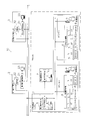
- FIG. 1 is a block diagram showing a configuration of a power distribution network system 10 according to an embodiment of the present invention.
- the harmonic detection system 1 in the embodiment according to the present invention is provided in a distribution network system 10.
- the harmonic detection system 1 detects a harmonic by monitoring the distribution network using a plurality of CT (Current Transformer) sensors 7 installed at predetermined positions of the distribution lines constituting the distribution network.
- CT Current Transformer
- a first power management center 2 and a second power management center 3 are provided in the power distribution network system 10 of the present embodiment.
- the first power management center 2 manages the distribution network in the block A.
- the first power management center 2 is not limited to the block A, and may manage a plurality of blocks.
- the second power management center 3 also manages the distribution network in one or a plurality of blocks.
- the first power management center 2 and the second power management center 3 are management centers provided in, for example, Kansai Electric Power and Chubu Electric Power.
- a block A indicates a prefecture or prefecture in charge of Kansai Electric Power, such as Osaka Prefecture or Nara Prefecture, and a block managed by the second power management center 3 indicates a prefecture in charge of central power such as Aichi Prefecture.
- the distribution network system 10 of the present embodiment includes a harmonic detection system 1 and a maintenance management center 4 in each block.
- the harmonic detection system 1 detects harmonics generated in the distribution network in each block.
- the maintenance management center 4 performs maintenance management of each block based on the detection result of the harmonic detection system 1.
- the harmonic detection system 1 includes a power management center 5, a plurality of data collection repeaters 6, a plurality of CT sensors 7, a smart meter 8, and a smartphone 9.
- the power management center 5 manages power in each block and detects an abnormality in the distribution network in the block.
- the data collection repeater 6 collects data from the plurality of CT sensors 7.
- a plurality of CT sensors 7 are installed for each electrical area flowing through the distribution line, and measure the current of the distribution line.
- the current of the distribution line is measured by the CT sensor 7, and data is sent from the CT sensor 7 to the power management center 5 via the data collection repeater 6, and harmonics are generated by the power management center 5 based on the data. Is detected.
- harmonics are detected, a warning message is transmitted to the smartphone 9 based on the registration information of the smart meter 8, and a warning is notified to the user G.
- the area indicates, for example, an area transmitted from a predetermined substation in a block or an area of a municipality such as a city or a town.
- one data collection repeater 6 is provided for each of a plurality of areas A-1,..., An, and data of a plurality of CT sensors 7 installed in one area is stored as one.
- two data collection repeaters 6 are collecting, the present invention is not limited to this.
- a plurality of data collection repeaters 6 may be provided in one area, and a plurality of data collection repeaters 6 may separately collect data from a plurality of CT sensors 7 installed in one area.
- the plurality of CT sensors 7 are divided into groups for which the data collection repeater 6 takes charge, and each data collection repeater 6 collects data of the plurality of CT sensors 7 belonging to the group.
- block A it can be said that one area that one data collection repeater 6 is in charge of constitutes one group.
- only one data collection repeater 6 may be provided in the area, or a plurality of data collection repeaters 6 may be provided.
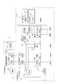
- FIG. 2 is a diagram showing the installation locations of the data collection repeater 6 and the CT sensor 7 in the power distribution network 100.
- a power pole 101 on the upstream side in the power transmission direction and a power pole 102 on the downstream side are shown, and the distribution lines 103, 104, and 105 are provided as three main lines constituting three phases of RST between the power pole 101 and the power pole 102. Is over. Electricity flows in the direction from the utility pole 101 to the utility pole 102.
- the distribution line 103 is an R-phase distribution line
- the distribution line 104 is an S-phase distribution line
- the distribution line 105 is a T-phase distribution line.
- the distribution lines 106, 107, and 108 branch from the distribution line 105 as branch lines, and are connected to the electrical facilities in the houses 109 and 110 and the factory 111.
- the data collection repeater 6 is installed in each of the utility pole 101 and the utility pole 102.
- the CT sensor 7 is a clamp type and is detachably installed on a distribution line (an example of a power line).
- the CT sensor 7 is installed in each of the distribution lines 103, 104, 105, 106, 107, 108.
- Distribution lines 106 and 107 are drawn into houses 109 and 110 via smart meter 8, respectively.
- the distribution line 108 is drawn into the factory 111 via the smart meter 8.
- one smart meter 8 is provided corresponding to one CT sensor 7.
- a unique ID is assigned to each of the CT sensor 7 and the smart meter 8, and the correspondence relationship between the CT sensor 7 and the smart meter 8 is specified by a setting information table 203 in the management DB 54 described later.
- the setting information table 203 in the management DB 54 described later indicates that the corresponding smart meter 8 does not exist in the CT sensor 7 installed in the distribution lines 103, 104, and 105.
- the data of the CT sensor 7 installed on the distribution lines 106 and 107 is transmitted to the data collection repeater 6 installed on the utility pole 102 and installed on the distribution lines 103, 104, 105 and 108.
- the data of the CT sensor 7 is transmitted to the data collection repeater 6 installed on the utility pole 101. Communication between the CT sensor 7 and the data collection repeater 6 is performed wirelessly.
- FIG. 3 is a block diagram showing the configuration of the data collection repeater 6 and the CT sensor 7.
- the customer D is provided with a CT sensor 7, a smart meter 8, and a smartphone 9.
- the consumer D indicates one of the house 109, the house 110, or the factory 111 in FIG. That is, a CT sensor 7, a smart meter 8, and a smartphone 9 are provided in each of the houses 109 and 110 and the factory 111.
- the CT sensor 7 includes a measurement unit 71, a power feeding unit 72, a transmission unit 73, a setting unit 74, an RTC (real time clock) 75, and an RTC control unit 76. It can be detachably attached to the distribution line.
- the measurement unit 71 measures the trend of the current flowing through the distribution line by the power supply from the power supply unit 72.
- the measuring unit 71 includes a coil unit that is detachably attached to the periphery of the distribution line, a shunt resistor for measuring a current flowing through the coil unit, and the like. By measuring the voltage across the shunt resistor, the current flowing through the distribution line can be detected.
- the measurement unit 71 is provided with a calculation unit (not shown), and the power spectrum values (dB) of the fundamental wave, the third harmonic, and the fifth harmonic of the current from the detected current waveform. ) Is calculated.
- the power supply unit 72 stores electricity generated in the coil unit and supplies power to the measurement unit 71.
- the structure which switches the direction of the electric current which arises in a coil part to the shunt resistance side or the electric power feeding part 72 side is provided, and the electric current which arises in a coil part when it accumulates in the electric power feeding part 72 is not supplied to a shunt resistance, The power is supplied to the power feeding unit 72. Further, when the current is measured by the measuring unit 71, no electricity flows to the power feeding unit 72 side.
- the setting unit 74 sets a sensor ID for identifying the CT sensor 7 (an example of measurement device identification information, an example of measurement unit identification information).
- the RTC control unit 76 acquires time information of timing at which the measurement unit 71 measures the current waveform from the RTC 75 and transmits the time information to the transmission unit 73.
- the transmission unit 73 wirelessly transmits the data (fundamental current, third harmonic, and fifth harmonic power spectrum values (dB)) measured and calculated by the measurement unit 71 to the data collection repeater 6. To do. These data are detection data used for detecting harmonics in the power management apparatus 51.
- the transmission unit 73 sends the sensor ID set by the setting unit 74 and the time information acquired by the RTC control unit 76 as measurement information in association with the detection data in addition to the detection data.
- the time information indicates the time when the current waveform is measured.
- the time information may be transmitted from the RTC control unit 76 to the measurement unit 71, and the time information may be added to the detection data in the measurement unit 71, or the measurement data may be transmitted from the measurement unit 71 to the RTC control unit 76. In the RTC control unit 76, time information may be given to the detection data.
- the CT sensor 7 periodically transmits the sensor ID, time information, and detection data to the data collection repeater 6 at intervals of 6 minutes, for example.
- the smart meter 8 includes a power measurement unit 81, a setting unit 82, and a transmission unit 83.
- the power measurement unit 81 measures the amount of power supplied to the customer D.
- the setting unit 82 sets a unique ID for the smart meter 8.
- the transmission unit 83 transmits the power used by the customer D measured by the power measurement unit 81 to the reception unit 57 a of the power management device 51. In addition, the transmission unit 83 transmits its own ID to the power management apparatus 51.
- the smartphone 9 includes a reception unit 91, a display unit 92, a usage fee confirmation input unit 93, and a transmission unit 94.
- the reception unit 91 receives a warning message based on the detection of harmonics from the transmission unit 44 of the maintenance management device 41.
- the receiving unit 91 receives a power usage fee from the transmission unit 58 b of the power management apparatus 51.
- the display unit 92 displays a warning message based on the abnormality notification.
- the usage fee confirmation input unit 93 is input by the user G to inquire about the power usage fee.
- the transmission unit 94 transmits a power usage inquiry to the reception unit 58 a of the power management apparatus 51.
- the data collection repeater 6 includes a communication unit 61, a management DB 62, and a communication unit 63.
- the communication unit 61 communicates with a plurality of CT sensors 7.
- the communication unit 61 includes a reception unit 61a and receives measurement information (sensor ID, time information, and detection data) transmitted from the plurality of CT sensors 7 by radio.
- the management DB 62 stores and manages setting information (see setting information table 201 in FIG. 7 described later) and measurement information data (see measurement information table 202 in FIG. 8 described later) transmitted from the plurality of CT sensors 7 as a table. To do.
- the communication unit 63 communicates with the power management device 51.
- the communication unit 63 includes a reception unit 63a and a transmission unit 63b.
- the receiving unit 63a receives a setting request and a data acquisition request from the power management apparatus 51 of the power management center 5.
- the data acquisition request is transmitted from the power management center 5 periodically (for example, at intervals of 60 minutes).
- the setting request requests setting of the management code of the data collection repeater 6.
- the transmitter 63b transmits the sensor ID, time information, detection data, and relay management code (an example of relay identification information) to the power management center 5.
- the power management center 5 includes a power management device 51 and a display unit 52.
- the power management device 51 uses the detection data received from the data collection repeater 6 to detect an abnormality in the distribution network.
- FIG. 4 is a block diagram showing configurations of the first power management center 2 and the power management center 5.
- the power management apparatus 51 includes a communication unit 53, a management DB 54, a communication unit 55, an abnormality determination unit 56, a communication unit 57, and a communication unit 58.
- the communication unit 53 communicates with the data collection repeater 6.
- the communication unit 53 includes a reception unit 53a and a transmission unit 53b. As shown in FIG. 1, the receiving unit 53a receives the sensor ID, time information, detection data, and relay management code transmitted from the transmission unit 63b of the plurality of data collection relays 6.
- the transmission unit 53b transmits a setting request and a data acquisition request to each data collection repeater 6.
- the management DB 54 stores the relay management code and sensor ID, time information, and detection data received via the receiving unit 53a. As described above, since the detection data is transmitted from the CT sensor 7 to the data collection repeater 6 every 6 minutes, the data collection relay is performed when the data acquisition request is transmitted to the data collection repeater 6 every 60 minutes. The detector 6 transmits the detection data for 10 times at a time to the power management apparatus 51. The management DB 54 uses these detection data (current spectrum, third harmonic, and fifth harmonic power spectrum values (dB)), sensor ID, time information, repeater management code, and area code. And store it as a table.
- detection data current spectrum, third harmonic, and fifth harmonic power spectrum values (dB)
- dB fifth harmonic power spectrum values
- the management DB 54 also stores a threshold for detecting an abnormality and detected detection result data (the presence / absence of abnormality and the degree of abnormality).
- the management DB 54 also stores and updates the setting information received from the first power management center 2.
- the communication unit 55 communicates with the first power management center 2.
- the communication unit 55 includes a reception unit 55a and a transmission unit 55b.
- the receiving unit 55a receives setting information from the first power management center 2.
- the transmission unit 55 b transmits detection result data to the first power management center 2.
- the abnormality determination unit 56 detects harmonics in the distribution network based on the detection data stored in the management DB 54.
- the abnormality determination unit 56 includes a harmonic abnormality determination unit 561, an abnormality registration unit 562, and an abnormality notification unit 563.
- the harmonic abnormality determining unit 561 detects whether or not a harmonic component is included in the current supplied from the distribution line.
- the harmonic abnormality determining unit 561 uses the power spectrum values (dB) of the current fundamental wave, the third harmonic wave, and the fifth harmonic wave of the detection data, and uses the third harmonic wave or the fifth harmonic wave as the fundamental wave. Detect whether a wave is included.
- the abnormality of the harmonic can be determined from the power spectrum value (dB) of each of the fundamental wave, the third harmonic, and the fifth harmonic of each current of the CT sensor 7 shown in FIG.
- the abnormality registration unit 562 registers the detection result data (the presence / absence of abnormality and the degree of abnormality) determined by the harmonic abnormality determination unit 561 in the management DB 54 together with the relay management code and the sensor ID.
- the abnormality notifying unit 563 notifies the detection result data registered by the abnormality registering unit 562 to the maintenance management center 4.
- the communication unit 57 communicates with the smart meter 8.
- the communication unit 57 includes a reception unit 57 a that receives a meter ID or an electric energy from the transmission unit 83 of the smart meter 8.
- the communication unit 58 communicates with the smartphone 9.
- the communication unit 58 includes a reception unit 58a and a transmission unit 58b.
- the receiving unit 58a receives an inquiry about a power usage fee transmitted from the transmitting unit 94 of the smartphone 9.
- the transmission unit 58b transmits a warning message or a power usage fee based on the detection result to the smartphone 9.
- the maintenance management center 4 performs maintenance management of the power distribution network 100 based on the notification of the abnormality detection result data from the power management center 5. That is, management is performed such as dispatching an operator to actually confirm the installation location of the CT sensor 7 that has transmitted the detection data in which the abnormality is detected.
- the maintenance management center 4 includes a maintenance management device 41 and a display unit 42 as shown in FIG. As shown in FIG. 2, the maintenance management device 41 includes an abnormality reception unit 43 and a transmission unit 44.
- the abnormality receiving unit 43 receives the detection result data transmitted from the abnormality notification unit 563 of the power management apparatus 51.
- the display unit 42 displays the detection result data, and the manager takes measures such as dispatching an operator to the site if necessary.
- the transmission unit 44 transmits the registration information of the user to the transmission destination. As a warning message.
- the first power management center 2 includes a first power management device 21, a management DB (Data base) 22, and a display unit 23.
- the first power management apparatus 21 has a communication unit 24 provided with a reception unit 24a and a transmission unit 24b, and communicates with the power management center 5 provided in each of the blocks. Do.
- the first power management device 21 receives the detection result data detected by each power management device 51 by the communication unit 24 and stores it in the management DB 22.
- the detection result data includes the presence / absence of abnormality and an attention level of abnormality
- the power management apparatus 51 includes the ID and position of the CT sensor 7 that measured the measurement data in which the abnormality was detected in the detection result data, the data collection relay 6
- the management code, the ID of the smart meter 8, the registration information of the user, the measurement time of the measurement data in which the abnormality is detected, and the like are added and transmitted to the first power management apparatus 21.
- the second power management center 3 has the same configuration as the first power management center 2, and as shown in FIG. 1, the second power management center 3 includes a second power management device 31 having a communication unit provided with a transmission unit and a reception unit.
- the management DB 32 and the display unit 33 are included.
- the second power management center 3 communicates with the power management center 5 provided in another block, and stores detection result data detected by the power management center 5.
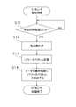
- FIG. 5 is a flowchart showing the operation of the CT sensor 7 of the harmonic detection system 1 of the present embodiment.
- step S11 When the process starts, when a predetermined charging time elapses in step S11, power is supplied from the power supply unit 72 and the measurement unit 71 measures the current of the distribution line in step S12.
- the predetermined charging time can be set to 6 minutes, for example, and in that case, a current is measured every 6 minutes.
- step S ⁇ b> 13 the measurement unit 71 calculates a power spectrum. The power spectrum values of the fundamental wave, the third harmonic, and the fifth harmonic of the current are obtained.
- FIG. 6 is a flowchart showing the operation of the data collection repeater 6 of the harmonic detection system 1 of the present embodiment.
- step S21 the data collection repeater 6 determines whether or not there is reception of data from the power management apparatus 51 via the communication unit 63. If no data is received from the power management apparatus 51, it is determined in step S22 whether data is received from the CT sensor 7 or not. If data is received, in step S23, the data collection relay device 6 stores the received measurement information in the management DB 62, and the processing of the data collection relay device 6 ends.
- step S24 determines whether a setting request is received.
- the received setting request is stored in the management DB 62, and the processing of the data collection relay device 6 is terminated.
- the data collection repeater 6 acquires the measurement information from the management DB 62.
- step S27 the data collection repeater 6 transmits the measurement information to the power management apparatus 51, and the processing of the data collection repeater 6 ends.
- sensor IDs, measurement times, and detection data are transmitted from the plurality of CT sensors 7 to the data collection repeater 6 at intervals of 6 minutes.
- the relay management code of the data collection relay 6, the sensor ID of the CT sensor 7, the time information, and the detection data are stored in association with each other as a database.
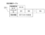
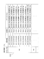
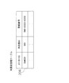
- FIG. 7 is a diagram showing the setting information table 201 stored in the management DB 62
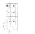
- FIG. 8 is a diagram showing the measurement information table 202 stored in the management DB 62.
- the management code (A01_01) of the data collection repeater 6, the ID (001, 002 to 00n) of the CT sensor 7, and time information are recorded.
- the setting information table 201 is updated by storing the setting information received from the power management apparatus 51.
- the measurement information table 202 includes an ID (01, 002 to 00n) of each CT sensor 7, a measurement time, and detection data (basic wave of current) of each CT sensor 7. , Third harmonic and fifth harmonic power spectrum values (dB)) are stored in association with each other.
- the management DB 62 stores the detection data and the time when the data was measured for each CT sensor 7.
- the measurement information table 202 is updated when detection data is received from the CT sensor 7.
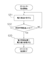
- FIG. 9 is a flowchart showing the operation of the smart meter 8.
- the smart meter 8 measures the amount of power in step S31, and the measurement of the amount of power is repeated until it is determined in step S32 that the predetermined time has elapsed. That is, the amount of power is measured until a predetermined time has elapsed.
- the predetermined time can be set to 24 hours, for example.
- step S32 when a predetermined time has elapsed, in step S33, the transmission unit 83 transmits the amount of power to the reception unit 57a of the power management apparatus 51.
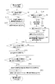
- FIG. 10 is a flowchart showing the operation of the power management apparatus 51 of the harmonic detection system 1 of the present embodiment.
- step S41 the power management apparatus 51 determines whether or not the data acquisition time has elapsed.
- the data acquisition time is set, for example, every 60 minutes.
- step S42 the power management apparatus 51 transmits a data acquisition request from the transmission unit 53b to the data collection repeater 6.
- the data collection relay device 6 wirelessly receives a data acquisition request from the power management device 51, the data collection relay device 6 transmits the measurement information stored in the management DB 62 to the power management device 51 via the transmission unit 53b.
- the power management apparatus 51 stores the measurement information in the management DB 54 in step S43.
- a table stored in the management DB 54 will be described.
- FIG. 11 is a diagram showing the setting information table 203 stored in the management DB 54
- FIG. 12 is a diagram showing the measurement information table 204 stored in the management DB 54
- FIG. 13 is a diagram showing the position information management table 205 stored in the management DB 54
- FIG. 14 is a diagram showing a user management table 206 stored in the management DB.
- the setting information table 203 includes an area code (for example, areas A-1, A-2, etc. in FIG. 1), a management code (A01_01) of the data collection repeater 6, a group ID, and a classification. ID, ID (001, 002 to 00n) of CT sensor 7, meter ID, and time information are recorded.
- the area code identifies each area.
- the repeater management code identifies the data collection repeater 6.
- the group ID indicates the type of the trunk line on which the CT sensor 7 is installed, and indicates whether the distribution line is installed on the R-phase, S-phase, or T-phase.
- the classification ID indicates whether the CT sensor 7 is installed on a trunk line or a branch line, BR00 indicates that it is installed on a trunk line, and BR01 indicates that it is installed on a branch line.
- the meter ID is given when there is a user registration, and one meter ID does not correspond to the sensor IDs of the plurality of CT sensors 7 but corresponds to the sensor ID of one CT sensor 7. When there is no user registration, no meter ID is given.
- the case where the meter ID is not given is a case where the CT sensor 7 is arranged on a distribution line (for example, distribution lines 103, 104, 105 which are trunk lines) where a specific user G does not exist.
- the distribution network 100 shown in FIG. 2 is provided in the area A01, the management code of the data collection repeater 6 installed in the utility pole 101 is A01_01, and the management code of the data collection repeater 6 installed in the utility pole 102 Is A01_02.
- the sensor ID of the CT sensor 7 installed in the distribution line 106 is 003
- the distribution line 106 is a branch line from the T-phase distribution line 105, so the group ID is set to R, and the classification ID is , BR01.
- the meter ID (sm000) indicates the ID of the smart meter 8 provided in the house 109 into which the distribution line 106 is drawn.
- the measurement information table 204 includes an area code, a relay management code, the ID (01, 002 to 00n) of each CT sensor 7, time information indicating the measurement time, and each CT sensor 7. Are stored in association with each other (detection value (dB) of the power spectrum of the fundamental wave, the third harmonic, and the fifth harmonic of the current).
- the position information management table 205 manages the position information of the CT sensor 7 installed in the area code.
- an area code, a relay management code, a CT sensor ID, and a position code are stored in association with each other. The location of the corresponding CT sensor 7 can be confirmed from the position code.
- the contact information of the smartphone 9 owned by the user G is registered as registration information.
- the meter ID indicates identification information of the smart meter 8 as described above, and the user ID is identification information of the user G in the customer D whose electric energy is measured by the smart meter 8.
- the registration number is a contact information of the smartphone 9 owned by the user G, and for example, a telephone number or an e-mail address is registered.
- the sensor ID of the CT sensor 7 and the meter ID of the smart meter 8 correspond one-to-one, the distribution line in which the current is measured by the CT sensor 7 and the CT sensor 7
- the contact information of the user in the customer who is being drawn in is linked. Thereby, when a harmonic is detected by the predetermined CT sensor 7, the contact information of the user corresponding to the CT sensor 7 is known.
- the setting information table 203 is updated by storing the setting information set by the power management apparatus 51.
- the measurement information table 204 is updated when measurement information is received from the data collection repeater 6.
- the position information management table 205 is updated when a new CT sensor 7 is installed or when the installation location of the CT sensor 7 is changed.
- the user management table 206 is updated when a user is changed or a smart meter 8 is newly installed.
- step S44 If the data acquisition time has not elapsed in step S41 described above, the power management apparatus 51 checks in step S44 whether or not the abnormality check time has elapsed. As an interval of this abnormality check, for example, an interval of 60 minutes can be set. If the abnormality check time has elapsed, harmonic abnormality determination processing is performed in step S45. The distribution line abnormality determination process will be described in detail later. If the abnormality check time has not elapsed, the process returns to step S41.
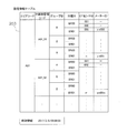
- FIG. 15 is a diagram showing an abnormality management table 207 that is an abnormality log recorded in the management DB.
- an area code (A01), a relay management code (A01_01 to A01_0n, A02_01%), A CT sensor ID (001%), A state, and a harmonic level are recorded.
- the state indicates normality or abnormality
- the harmonic level indicates the attention level in the case of abnormality in three stages.
- step S49 the power management apparatus 51 determines whether or not the reception unit 57a has received the amount of power from the smart meter 8. When the power amount is received in step S49, the power management apparatus 51 stores the received power amount in the management DB 54 in step S50.
- step S51 the power management apparatus 51 determines whether or not the reception unit 58a has received a power usage fee inquiry from the smartphone 9. If an inquiry about the power usage fee is received in step S51, in step S52, the power management apparatus 51 acquires the power usage fee of the corresponding user from the management DB.
- step S53 the power management apparatus 51 transmits a power usage fee to the smartphone 9 of the corresponding user G.
- the distribution line abnormality determination process in step S45 will be described below. (Harmonic judgment processing)
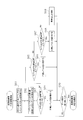
- FIG. 16 is a flowchart showing harmonic determination processing in step S45 in FIG.
- step S61 the harmonic abnormality determination unit 561 of the abnormality determination unit 56 acquires the power spectrum of the corresponding CT sensor 7 from the management DB 54.
- the harmonic abnormality determination power spectra of all CT sensors 7 are acquired.
- the power spectrum is calculated from the current waveform in the measurement unit 71 of the CT sensor 7, and the harmonic abnormality determination unit 561 acquires the power spectrum of the fundamental wave, the third harmonic, and the fifth harmonic.
- FIG. 17 is a diagram showing a power spectrum.
- the harmonic abnormality determining unit 561 calculates a distortion rate (also referred to as a harmonic content rate) due to the nth harmonic from the power spectrum.
- the harmonic abnormality determining unit 561 uses the fundamental wave, the third harmonic wave, and the fifth harmonic power spectrum [dB] to determine the harmonic content for each frequency (the fundamental wave of the harmonic power spectrum of a predetermined order). The ratio to the power spectrum is calculated.
- the distortion rate (distortion_rate). ) Can be obtained by the following equation (1).
- step S63 the harmonic abnormality determining unit 561 determines whether or not the calculated two distortion rates exceed a third threshold set for each.
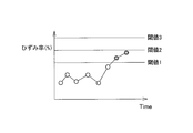
- the management DB 54 stores a first threshold value, a second threshold value, and a third threshold value that are set in advance for each of the third harmonic and the fifth harmonic. The values are set to increase in the order of the first threshold value, the second threshold value, and the third threshold value, and the attention level increases in order.
- step S63 when the harmonic abnormality determination unit 561 determines that any one of the two calculated distortion rates exceeds the third threshold, the abnormality registration unit 562 is at attention level 3 in step S64.
- the harmonic abnormality determination unit 561 sets the second threshold value for which two distortion factors are set for each in step S65. Determine if it has exceeded.
- step S65 when it is determined by the harmonic abnormality determination unit 561 that either one of the two calculated distortion rates exceeds the second threshold value, the abnormality registration unit 562 is at attention level 2 in step S66.
- the harmonic abnormality determination unit 561 first sets the two distortion rates for each in step S68. It is determined whether or not the threshold value is exceeded.
- step S67 when it is determined by the harmonic abnormality determination unit 561 that either one of the two calculated distortion rates exceeds the first threshold, the abnormality registration unit 562 is at attention level 1 in step S68.
- the harmonic abnormality determining unit 561 determines in step S69 that there is no abnormality.
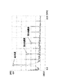
- FIG. 18 is a figure which shows the graph of the time change of a distortion factor. Since the data indicated by the double circles in the figure exists between the first threshold value and the second threshold value, it can be seen that the attention level is 1.
- step S47 the abnormality registration unit 562 stores an abnormality log in the management DB 54 using the abnormality management table 207 shown in FIG. Remember. (Operation of maintenance management device) Next, the operation of the maintenance management apparatus 41 will be described.
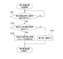
- FIG. 19 is a flowchart showing the operation of the maintenance management device 41.
- step S81 the maintenance management device 41 determines whether or not there is an abnormality notification from the power management device 51. If there is an abnormality notification, it is determined in step S82 whether or not the corresponding user is registered.
- the power management device 51 sends the area code, the relay management code, the sensor ID, the state, the harmonic level (see the abnormality management table 207), and the meter ID (setting) corresponding to the sensor ID to the maintenance management device 41.
- a user ID corresponding to the meter ID, a registration number (user management table 206), and a position code (position information management table 205) are transmitted. If no user registration is made, the meter ID is not given to the setting information table 203, so the maintenance management apparatus 41 can determine that there is no user registration.
- step S82 If no corresponding user registration exists in step S82, the maintenance staff is notified in step S83. As a result, the maintenance staff can visit the installation location (specified by the position code) of the CT sensor 7 that has detected the harmonics, and can investigate and deal with the cause of the high frequency.
- step S84 the maintenance management device 41 transmits a warning message (an example of notification) with the user registration number as the transmission destination.
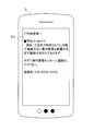
- FIG. 20 shows a state in which a warning message is displayed on the display unit 92 of the smartphone 9 owned by the user.
- a warning message (an example of notification) is displayed on a smartphone 9 as an example of a notification device.
- the present invention is not limited to the smartphone 9, and may be a television, a personal computer, or the like.
- the warning message is notified from the transmission unit 44 as an example of the first transmission unit to the smartphone 9, but the present invention is not limited to this, and the warning message is notified from the power management device 51 to the smartphone 9. May be.
- a warning message can be displayed on the smartphone 9 from the transmission unit 58b (an example of the first transmission unit) of the power management apparatus 51, and the transmission unit 58b corresponds to an example of the first transmission unit.
- the contact information of the CT sensor 7 and the user G is linked via the meter ID of the smart meter 8.
- the contact information of G may also be set in the management DB 54. In short, when a harmonic is detected, it is only necessary to be able to guide the contact person of the user G of the power of the distribution line in which the CT sensor 7 is installed from the CT sensor 7 that has detected the harmonic.
- the said power management apparatus 51 demonstrated that it was provided in units, such as a prefecture, for example, it is not restricted to this,
- the area or city transmitted from the predetermined substation It may be provided in units of municipal areas such as towns and towns. Further, the power management device 51 may be provided in a cubicle, for example.
- the measurement information of the CT sensor 7 is once collected by the data collection repeater 6 and then transmitted to the power management device 51.
- the present invention is not limited to this.
- the data collection repeater 6 may not be provided in the harmonic detection system 1, and in this case, measurement information is directly transmitted from the CT sensor 7 to the power management apparatus 51 via radio.
- the power spectrum is calculated by the CT sensor 7 and the harmonic management is detected from the power spectrum by the power management device 51.
- the present invention is not limited to this.
- a power spectrum may be calculated by the CT sensor 7 and a harmonic abnormality detection process may be performed by the data collection repeater 6. Further, the CT sensor 7 may perform processing up to detecting a harmonic abnormality.
- all or part of the current waveform data detected by the CT sensor 7 may be transmitted to the data collection repeater 6, and the power spectrum of the current may be calculated in the data collection repeater 6. Furthermore, in the data collection repeater 6, a power spectrum may be calculated, and harmonic abnormality detection processing may be performed from the power spectrum. Furthermore, the power spectrum of the current may not be calculated in the CT sensor 7 and the data collection repeater 6, and the power spectrum may be calculated in the power management apparatus 51, and a harmonic abnormality detection process may be performed from the power spectrum.
- the harmonic abnormality determination unit 561 may calculate the harmonic content of the seventh harmonic or higher and detect the harmonic.
- the distortion rate is calculated using (Equation 1), and it is determined that harmonics are included when the distortion rate exceeds a predetermined threshold.
- the present invention is not limited to this. It is only necessary to detect that the fundamental wave includes harmonics.
- the power management device 51 is provided with the abnormality determination unit 56 and the power management device 51 determines the abnormality.
- the present invention is not limited to this.
- the data collection repeater 6 ′ is provided with an abnormality determination unit 56 ′ having a harmonic abnormality determination unit 561 and an abnormality registration unit 562, and the data collection repeater 6 determines abnormality. It may be broken. It should be noted that only the abnormality detection result data detected by the data collection repeater 6 ′ may be transmitted from the data collection repeater 6 ′ to the power management apparatus 51.
- This abnormality detection result data is, for example, data indicating a state (abnormality presence / absence, abnormality level) as shown in FIG.
- the power management apparatus 51 stores abnormality detection result data in the management DB 54 in association with a relay management code (an example of relay identification information) and a sensor ID (an example of measuring device identification information).
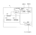
- the CT sensor 7 may be provided with a harmonic abnormality determining unit 561, and the CT sensor 7 may determine abnormality.
- a CT sensor 7 ′ having such a configuration is shown in FIG. 22.
- the CT sensor 7 ′ is provided with an abnormality determination unit 56 ′′ having a harmonic abnormality determination unit 561 and an abnormality registration unit 562, and a management DB 77.
- the abnormality determination unit 56 determines abnormality, and the abnormality detection result data is stored in the management DB 77 together with time information. Then, the data collection repeater 6 and the power management apparatus 51 store the detection result in association with the sensor ID and time information.
- the RTC 75 and the RTC control unit 76 are provided in the CT sensor 7, but the RTC 75 and the RTC control unit 76 are not provided in the CT sensor 7, and the RTC 75 and the RTC control are provided in the data collection relay 6. A portion 76 may be provided. That is, in the above embodiment, the time information is transmitted from the CT sensor 7 to the data collection repeater 6.
- FIG. 23 is a block diagram showing a CT sensor 7 ′′ not provided with the RTC 75 and the RTC control unit 76, and a data collection repeater 6 ′′ provided with the RTC 75 and the RTC control unit 76.
- the CT sensor 7 ′′ shown in FIG. 23 performs measurement by the measuring unit 71, it transmits measurement data (power spectrums of the fundamental wave, the third harmonic, and the fifth harmonic) to the data collection repeater 6 ′′.
- the RTC control unit 76 transmits the time information acquired from the RTC 75 to the management DB 62, and the management DB 62 adds the time information to the measurement data transmitted from the CT sensor 7 ′′.
- Store see measurement information table 202 in FIG. 8).
- the transmission unit 63 b of the data collection repeater 6 ′′ transmits the relay management code, sensor ID, item information, and detection data to the power management apparatus 51.
- the power management device 51 has the abnormality notification unit 563 as an example of the second transmission unit, and the power management device 51 reports the abnormality, but the above (H-1)
- the data collection relay device 6 may include the abnormality notification unit 563.
- the CT sensor 7 may include the abnormality notification unit 563.
- the abnormality notification is not limited to notifying the maintenance management center 4 but may emit light or sound.
- the control method and the abnormality detection method are performed according to the flowcharts shown in FIGS. 5, 6, 9, 10, 16, and 19 as the harmonic detection system control method and the harmonic detection method. Although an example of carrying out has been described, the present invention is not limited to this.
- harmonic detection program for causing a computer to execute all or part of the harmonic detection method implemented in accordance with the flowcharts shown in FIGS. 5, 6, 9, 10, 16, and 19, the present invention is described. It may be realized. Further, one usage form of the harmonic detection program may be an aspect in which the program is recorded on a recording medium such as a ROM readable by a computer and operates in cooperation with the computer.
- one usage form of the harmonic detection program is an aspect in which it is transmitted through a transmission medium such as the Internet or a transmission medium such as light, radio wave, or sound wave, read by a computer, and operated in cooperation with the computer. May be.
- the computer described above is not limited to hardware such as a CPU, and may include firmware, an OS, and peripheral devices.
- harmonic detection may be realized by software or hardware.
- the harmonic detection system of the present invention has the effect of being able to quickly detect anomalies at a low cost. For example, monitoring of harmonics in a distribution network in a country where power infrastructure is underdeveloped, such as India and ASEAN countries. Widely applicable to etc.
- Harmonic detection system 2 First power management center 3: Second power management center 4: Maintenance management center 5: Power management center 6: Data collection relay (an example of a relay) 6 ': Data collection repeater (an example of a repeater) 6 ′′: Data collection repeater (an example of a repeater) 7: CT sensor (an example of a measuring instrument) 7 ': CT sensor (an example of a measuring instrument) 7 ′′: CT sensor (an example of a measuring instrument) 8: Smart meter 9: Smartphone (an example of a notification device) 10: Distribution network system 21: First power management device 22: Management DB 23: Display unit 24: Communication unit 24a: Reception unit 24b: Transmission unit 31: Second power management device 32: Management DB 33: Display unit 41: Maintenance management device (an example of a maintenance device) 42: Display unit 43: Abnormal reception unit 44: Transmission unit (an example of a first transmission unit) 51: Power management device (an example of a management device) 52: Display unit 53: Communication unit 53a: Reception unit 53b: Transmission
Landscapes
- Physics & Mathematics (AREA)
- Engineering & Computer Science (AREA)
- Power Engineering (AREA)
- General Physics & Mathematics (AREA)
- Mathematical Physics (AREA)
- Computer Networks & Wireless Communication (AREA)
- Signal Processing (AREA)
- Acoustics & Sound (AREA)
- Automation & Control Theory (AREA)
- Nonlinear Science (AREA)
- Remote Monitoring And Control Of Power-Distribution Networks (AREA)
- Locating Faults (AREA)
Abstract
高調波検出システム(1)は、計測部(71)と、高調波異常判定部(561)と、スマートフォン(9)とを、備える。計測部(71)は、配電網(100)を構成する配電線の所定位置に設置され、配電線の電流に関するデータの測定を行う。高調波異常判定部(561)は、電流に関するデータの全部または一部のデータを検出用データとして用いて、高調波に関する異常の検出を行う。スマートフォン(9)は、利用者(G)によって所有され、高調波が検出された際に、配電線に異常が生じていることを利用者に通知する。
Description
本発明は、高調波を検出する高調波検出システムに関する。
従来、配電網におけるハーモニック(高調波)の監視は、作業者による定期的な巡回によって行われている。作業者は、巡回の際に、所定位置または所定位置の間において電力線上で電気的な計測を行い、高調波に関する異常を検出する。
このような巡回において電気的な計測を行う際には、電力線に対して取り付けられ、CT(Current Transformer)によって電力線を流れる電流の波形を計測する計測装置が用いられる(例えば、特許文献1参照。)。
このような巡回において電気的な計測を行う際には、電力線に対して取り付けられ、CT(Current Transformer)によって電力線を流れる電流の波形を計測する計測装置が用いられる(例えば、特許文献1参照。)。
しかしながら、上記のような高調波の監視では、巡回の際に計測場所まで複数の作業者が訪れる必要があるため、計測に時間を要し、計測にかかるコストが大きくなる。また、定期的な巡回の間の期間における異常検出ができないため、突発的な異常の迅速な発見が困難である。
本発明の課題は、低コストで迅速に高調波を検出することが可能な高調波検出システムを提供することにある。
(課題を解決するための手段)
第1の発明にかかる高調波検出システムは、測定部と、高調波検出部と、通知装置とを、備える。測定部は、配電網を構成する電力線の所定位置に設置され、電力線の電流に関するデータの測定を行う。高調波検出部は、電流に関するデータの全部または一部のデータを検出用データとして用いて、高調波に関する異常の検出を行う。通知装置は、電力線によって供給される電力の利用者によって所有され、高調波が検出された際に、電力線に異常が生じていることを利用者に通知する。
本発明の課題は、低コストで迅速に高調波を検出することが可能な高調波検出システムを提供することにある。
(課題を解決するための手段)
第1の発明にかかる高調波検出システムは、測定部と、高調波検出部と、通知装置とを、備える。測定部は、配電網を構成する電力線の所定位置に設置され、電力線の電流に関するデータの測定を行う。高調波検出部は、電流に関するデータの全部または一部のデータを検出用データとして用いて、高調波に関する異常の検出を行う。通知装置は、電力線によって供給される電力の利用者によって所有され、高調波が検出された際に、電力線に異常が生じていることを利用者に通知する。
このように、高調波に関する異常の検出ができ、その検出結果を利用者が所有する通知装置によって利用者に通知することができる。
このため、異常の検出を利用者が認識することができ、作業者が定期的に巡回して監視を行わなくてもよくなり、コストを下げることが可能となる。
また、測定部を常時電力線に設置することが可能なため、電力線の電流の測定を所望のタイミングで行うことができ、配電網の異常を迅速に検出することができる。
このため、異常の検出を利用者が認識することができ、作業者が定期的に巡回して監視を行わなくてもよくなり、コストを下げることが可能となる。
また、測定部を常時電力線に設置することが可能なため、電力線の電流の測定を所望のタイミングで行うことができ、配電網の異常を迅速に検出することができる。
また、利用者が、自身が利用する電力線に高調波に関する異常が発生していることを認識できため、利用者内の電気設備を確認することによって、利用者が異常に対処することができる場合もある。
第2の発明にかかる高調波検出システムは、第1の発明にかかる高調波検出システムであって、第1送信部を更に備える。第1送信部は、高調波が検出された場合に、電力線によって供給される電力の利用者の登録が存在するとき、通信装置に高調波の検出に関する情報を送信する。
第2の発明にかかる高調波検出システムは、第1の発明にかかる高調波検出システムであって、第1送信部を更に備える。第1送信部は、高調波が検出された場合に、電力線によって供給される電力の利用者の登録が存在するとき、通信装置に高調波の検出に関する情報を送信する。
これにより、通知装置が例えば利用者が所有する携帯端末などに、高調波が検出されたことを利用者の携帯端末に送信することができるため、利用者に迅速に知らせることが可能となる。
第3の発明にかかる高調波検出システムは、第1または2の発明にかかる高調波検出システムであって、測定器と、管理装置とを更に備える。測定器は、測定部を有し、検出用データを送信する。管理装置は、高調波検出部を有し、検出用データを受信する。
第3の発明にかかる高調波検出システムは、第1または2の発明にかかる高調波検出システムであって、測定器と、管理装置とを更に備える。測定器は、測定部を有し、検出用データを送信する。管理装置は、高調波検出部を有し、検出用データを受信する。
これにより、管理装置において自動で高調波の異常の検出を行うことが可能となる。
第4の発明にかかる高調波検出システムは、第3の発明にかかる高調波検出システムであって、測定器は、複数の電力線の各々に設置されている。高調波検出システムは、中継器を更に備える。中継器は、複数の測定器から送信された検出用データを受信し、管理装置に送信する。
第4の発明にかかる高調波検出システムは、第3の発明にかかる高調波検出システムであって、測定器は、複数の電力線の各々に設置されている。高調波検出システムは、中継器を更に備える。中継器は、複数の測定器から送信された検出用データを受信し、管理装置に送信する。
これにより、中継器によって、複数の測定器の検出用データを一旦収集してから、管理装置へと送信することができる。
第5の発明にかかる高調波検出システムは、第1または2の発明にかかる高調波検出システムであって、測定器と、中継器と、管理装置とを更に備える。測定器は、測定部を有し、検出用データを送信する。中継器は、高調波検出部を有し、検出用データを受信し、高調波検出部による検出結果に関する検出結果データを送信する。管理装置は、検出結果データを受信する。
第5の発明にかかる高調波検出システムは、第1または2の発明にかかる高調波検出システムであって、測定器と、中継器と、管理装置とを更に備える。測定器は、測定部を有し、検出用データを送信する。中継器は、高調波検出部を有し、検出用データを受信し、高調波検出部による検出結果に関する検出結果データを送信する。管理装置は、検出結果データを受信する。
これにより、中継器において異常の検出が行われ、異常検出結果を上位の管理装置に送信することができる。このため、上位の管理装置に送信されるデータ量を減らすことができ、データ送信に使用する消費電力を抑制することができる。
また、管理装置等の上位システムにおけるデータ処理を簡素化することができる。合わせて、送信データの縮小により管理装置に接続する中継器の接続数を増やすことが可能となる。
また、管理装置等の上位システムにおけるデータ処理を簡素化することができる。合わせて、送信データの縮小により管理装置に接続する中継器の接続数を増やすことが可能となる。
第6の発明にかかる高調波検出システムは、第1または2の発明にかかる高調波検出システムであって、測定器と、管理装置とを更に備える。測定器は、測定部と、高調波検出部と、を有し、高調波検出部による高調波の検出結果に関する検出結果データを送信する。管理装置は、検出結果データを受信する。
これにより、測定器において、異常の検出が行われ、その異常検出結果を管理装置に送信することができる。このため、管理装置に送信されるデータ量を減らすことができ、データ送信に使用する消費電力を抑制することができる。
これにより、測定器において、異常の検出が行われ、その異常検出結果を管理装置に送信することができる。このため、管理装置に送信されるデータ量を減らすことができ、データ送信に使用する消費電力を抑制することができる。
また、管理装置等の上位システムにおけるデータ処理を簡素化することができる。合わせて、送信データの縮小により管理装置に接続する測定器の接続数を増やすことが可能となる。
なお、測定器と管理装置の間に中継器が設けられていてもよい。
第7の発明にかかる高調波検出システムは、第2の発明にかかる高調波検出システムであって、第2送信部を更に備える。第2送信部は、高調波検出部が高調波を検出した場合に、電力線を保守する保守装置に、高調波検出部による検出結果に関する検出結果データを送信する。第1送信部は、保守装置に設けられている。
なお、測定器と管理装置の間に中継器が設けられていてもよい。
第7の発明にかかる高調波検出システムは、第2の発明にかかる高調波検出システムであって、第2送信部を更に備える。第2送信部は、高調波検出部が高調波を検出した場合に、電力線を保守する保守装置に、高調波検出部による検出結果に関する検出結果データを送信する。第1送信部は、保守装置に設けられている。
これにより、高調波が検知された電力線を含む配電網を保守する保守装置に、高調波の検出を知らせ、保守装置から通知装置に高調波の検出に関する情報を送信することができる。
第8の発明にかかる高調波検出システムは、第1~7のいずれかの発明にかかる高調波検出システムであって、検出用データは、電力線の電流の基本波および基本波に対する高調波の情報を含む。
第8の発明にかかる高調波検出システムは、第1~7のいずれかの発明にかかる高調波検出システムであって、検出用データは、電力線の電流の基本波および基本波に対する高調波の情報を含む。
このように、電力線の電流の波形から基本波および高調波を求めることにより、高調波に関する異常を検出することが出来る。
第9の発明にかかる高調波検出システムは、第8の発明にかかる高調波検出システムであって、基本波および高調波に関する情報は、基本波および高調波のパワースペクトルである。高調波検出部は、基本波に対する高調波の比率が予め設定された閾値以上の場合、基本波に高調波が含まれていると判定する。
第9の発明にかかる高調波検出システムは、第8の発明にかかる高調波検出システムであって、基本波および高調波に関する情報は、基本波および高調波のパワースペクトルである。高調波検出部は、基本波に対する高調波の比率が予め設定された閾値以上の場合、基本波に高調波が含まれていると判定する。
このように、基本波および高調波についてパワースペクトル値を算出することにより、高調波の異常を算出することができるため、高調波の発生を迅速に検出でき、対処することが可能となる。
第10の発明にかかる高調波検出システムは、第9の発明にかかる高調波検出システムであって、閾値は、段階的に値が大きくなるように複数設定されている。高調波検出部は、大きい閾値を超える程、高調波による異常の程度が大きいと判定する。
第10の発明にかかる高調波検出システムは、第9の発明にかかる高調波検出システムであって、閾値は、段階的に値が大きくなるように複数設定されている。高調波検出部は、大きい閾値を超える程、高調波による異常の程度が大きいと判定する。
このように異常の程度を判別することができるため、程度が大きい異常になるほど迅速に対処することができる。
例えば、閾値を、注意レベルの値、要対処レベルの値、および緊急対処レベルの値に設定し、対処の優先順位を決定することができる。
第11の発明にかかる高調波検出システムは、第8の発明にかかる高調波検出システムであって、基本波に対する高調波の情報は、基本波に対する3次高調波と5次高調波の情報を少なくとも含む。
例えば、閾値を、注意レベルの値、要対処レベルの値、および緊急対処レベルの値に設定し、対処の優先順位を決定することができる。
第11の発明にかかる高調波検出システムは、第8の発明にかかる高調波検出システムであって、基本波に対する高調波の情報は、基本波に対する3次高調波と5次高調波の情報を少なくとも含む。
次数が小さいほど基本波に含まれる比率が大きくなるため、少なくとも3次高調波と5次高調波まで確認することによって、高調波に関する異常が発生しているか否かを判定することができる。
第12の発明にかかる高調波検出システムは、第1の発明にかかる高調波検出システムであって、記憶部を更に備える。記憶部は、測定部と、通知の送信先である通知装置とを関連付けて記憶する。
第12の発明にかかる高調波検出システムは、第1の発明にかかる高調波検出システムであって、記憶部を更に備える。記憶部は、測定部と、通知の送信先である通知装置とを関連付けて記憶する。
これによって、測定部によって測定した結果を、その測定部が測定した電力線を利用する利用者に対して知らせることができる。
第13の発明にかかる高調波検出システムは、第12の発明にかかる高調波検出システムであって、スマートメータを更に備える。スマートメータは、電力線に供給された電力量を検出する。記憶部は、測定部の識別情報と、測定部が設置された電力線の電力を測定するスマートメータの識別情報とを関連付けて記憶し、スマートメータに固有の識別情報と、スマートメータを所有する利用者の通知装置とを関連付けて記憶する。
第13の発明にかかる高調波検出システムは、第12の発明にかかる高調波検出システムであって、スマートメータを更に備える。スマートメータは、電力線に供給された電力量を検出する。記憶部は、測定部の識別情報と、測定部が設置された電力線の電力を測定するスマートメータの識別情報とを関連付けて記憶し、スマートメータに固有の識別情報と、スマートメータを所有する利用者の通知装置とを関連付けて記憶する。
スマートメータを設置する際には、スマートメータが設置される利用者の連絡先(ここでは、通知装置)が登録される。このスマートメータの識別情報を介して、測定部と利用者の連絡先が紐付けられるため、測定部によって測定した結果を、対応する利用者に知らせることができる。
第14の発明にかかる高調波検出システムは、第4の発明にかかる高調波検出システムであって、中継器は、複数設けられている。複数の測定器は、複数のグループに分けられている。各々の中継器は、各々のグループに属する複数の測定器から測定器の識別情報と検出用データを受信し、測定器の識別情報と検出用データとともに、中継器の識別情報を管理装置に送信する。管理装置は、記憶部を有する。記憶部は、検出用データを測定器の識別情報および中継器の識別情報と関連付けて記憶する。
第14の発明にかかる高調波検出システムは、第4の発明にかかる高調波検出システムであって、中継器は、複数設けられている。複数の測定器は、複数のグループに分けられている。各々の中継器は、各々のグループに属する複数の測定器から測定器の識別情報と検出用データを受信し、測定器の識別情報と検出用データとともに、中継器の識別情報を管理装置に送信する。管理装置は、記憶部を有する。記憶部は、検出用データを測定器の識別情報および中継器の識別情報と関連付けて記憶する。
これにより、グループごとに複数の測定器を中継器が担当することができ、さらに中継器の識別情報を介して、どの測定器によって異常が検出されたかを特定することができる。
また、担当していないグループの測定器の検出用データについては、不要データとして除外することができる。
また、担当していないグループの測定器の検出用データについては、不要データとして除外することができる。
第15の発明にかかる高調波検出システムは、第5の発明にかかる高調波検出システムであって、測定器は、複数設けられている。中継器は、複数設けられている。複数の測定器は、複数のグループに分けられている。各々の中継器は、各々のグループに属する複数の測定器から測定器の識別情報と検出用データを受信し、測定器の識別情報と検出結果データとともに、中継器の識別情報を管理装置に送信する。管理装置は、記憶部を有する。記憶部は、検出結果データを測定器の識別情報および中継器の識別情報と関連付けて記憶する。
これにより、グループごとに複数の測定器を中継器が担当することができ、さらに中継器の識別情報を介して、どの測定器によって異常が検出されたかを特定することができる。
また、担当していないグループの測定器の検出結果データについては、不要データとして除外することができる。
また、担当していないグループの測定器の検出結果データについては、不要データとして除外することができる。
第16の発明にかかる高調波検出システムは、第6の発明にかかる高調波検出システムであって、管理装置は、記憶部を有する。記憶部は、測定器の識別情報と検出結果データと関連付けて記憶する。
これにより、どの測定器によって異常が検出されたかを特定することができる。
第17の発明にかかる高調波検出システムは、第1の発明にかかる高調波検出システムであって、記憶部を更に備える。記憶部は、検出用データまたは高調波検出部による検出結果に関する検出結果データを時刻情報と関連付けて記憶する。
これにより、どの測定器によって異常が検出されたかを特定することができる。
第17の発明にかかる高調波検出システムは、第1の発明にかかる高調波検出システムであって、記憶部を更に備える。記憶部は、検出用データまたは高調波検出部による検出結果に関する検出結果データを時刻情報と関連付けて記憶する。
これにより、異常が検出された時刻または検出用データが測定された時刻を管理することができる。このため、例えば、特定の時刻に高調波が検出されることが確認された場合、その高調波は、特定の時刻に稼働している施設や機器などから発生されていると推定することが可能となる。
第18の発明にかかる高調波検出システムは、測定部と、高調波検出部と、送信部とを備える。測定部は、配電網を構成する電力線の所定位置に設置され、電力線の電流に関するデータの測定を行う。高調波検出部は、電流に関するデータの全部または一部のデータを検出用データとして用いて、高調波の検出を行う。送信部は、高調波検出部が高調波を検出した場合に、電力線を保守する保守装置に、高調波検出部による検出結果に関する検出結果データを送信する。
第18の発明にかかる高調波検出システムは、測定部と、高調波検出部と、送信部とを備える。測定部は、配電網を構成する電力線の所定位置に設置され、電力線の電流に関するデータの測定を行う。高調波検出部は、電流に関するデータの全部または一部のデータを検出用データとして用いて、高調波の検出を行う。送信部は、高調波検出部が高調波を検出した場合に、電力線を保守する保守装置に、高調波検出部による検出結果に関する検出結果データを送信する。
これにより、高調波が検知された電力線を含む配電網を保守する保守装置に、高調波の検出を知らせ、保守装置から通知装置に高調波の検出に関する情報を送信することができる。
(発明の効果)
本発明によれば、低コストで迅速に異常を検出することが可能な高調波検出システムを提供することが出来る。
(発明の効果)
本発明によれば、低コストで迅速に異常を検出することが可能な高調波検出システムを提供することが出来る。
以下に、本発明の実施の形態に係る高調波検出システムについて図面に基づいて説明する。
<構成>
(配電網システム10の概要)
図1は、本発明に係る実施の形態における配電網システム10の構成を示すブロック図である。
<構成>
(配電網システム10の概要)
図1は、本発明に係る実施の形態における配電網システム10の構成を示すブロック図である。
本発明に係る実施の形態における高調波検出システム1は、配電網システム10に設けられている。高調波検出システム1は、配電網を構成する配電線の所定の位置に設置された複数のCT(Current Transformer)センサ7を用いて配電網の監視を行い高調波の検出を行う。
本実施の形態の配電網システム10には、第1電力管理センタ2および第2電力管理センタ3が設けられている。第1電力管理センタ2は、ブロックAにおける配電網の管理を行っている。第1電力管理センタ2は、ブロックAだけに限らず、複数のブロックの管理を行ってもよい。第2電力管理センタ3も、第1電力管理センタ2と同様に、1つまたは複数のブロックにおける配電網の管理を行う。
本実施の形態の配電網システム10には、第1電力管理センタ2および第2電力管理センタ3が設けられている。第1電力管理センタ2は、ブロックAにおける配電網の管理を行っている。第1電力管理センタ2は、ブロックAだけに限らず、複数のブロックの管理を行ってもよい。第2電力管理センタ3も、第1電力管理センタ2と同様に、1つまたは複数のブロックにおける配電網の管理を行う。
ここで、第1電力管理センタ2および第2電力管理センタ3は、例えば、関西電力、中部電力などに設けられている管理センタである。また、ブロックAは、例えば大阪府、奈良県等の関西電力が担当する府または県を示し、第2電力管理センタ3が管理するブロックは、愛知県等の中部電力が担当する県を示す。
本実施の形態の配電網システム10は、各ブロックに、高調波検出システム1と、保守管理センタ4とを備える。高調波検出システム1は、各ブロックにおける配電網に生じる高調波の検出を行う。保守管理センタ4は、高調波検出システム1の検出結果に基づいて各ブロックの保守管理を行う。
本実施の形態の配電網システム10は、各ブロックに、高調波検出システム1と、保守管理センタ4とを備える。高調波検出システム1は、各ブロックにおける配電網に生じる高調波の検出を行う。保守管理センタ4は、高調波検出システム1の検出結果に基づいて各ブロックの保守管理を行う。
高調波検出システム1は、電力管理センタ5と、複数のデータ収集中継器6と、複数のCTセンサ7と、スマートメータ8と、スマートフォン9と、を有する。電力管理センタ5は、各ブロックにおける電力の管理を行い、ブロック内の配電網の異常を検出する。データ収集中継器6は、複数のCTセンサ7からデータを収集する。CTセンサ7は、配電線を流れる電気的なエリアごとに複数設置されており、配電線の電流の測定を行う。
配電線の電流がCTセンサ7によって測定されており、CTセンサ7からデータがデータ収集中継器6を経由して電力管理センタ5に送られ、そのデータに基づいて、電力管理センタ5によって高調波の検出が行われる。高調波が検出された場合には、スマートメータ8の登録情報に基づいて、スマートフォン9に警告メッセージが送信され、利用者Gに警告が通知される。
ここで、エリアとは、例えば、ブロック内において所定の変電所から送信されている区域若しくは、市や町などの市町村の区域を示す。
ブロックAでは、複数のエリアA-1・・・A-nのエリア毎に1つのデータ収集中継器6が設けられており、1つのエリアに設置されている複数のCTセンサ7のデータを1つのデータ収集中継器6が収集しているが、これに限らなくてもよい。1つのエリアに複数のデータ収集中継器6が設けられており、複数のデータ収集中継器6が1つのエリアに設置されている複数のCTセンサ7のデータを分けて収集してもよい。このような場合、複数のCTセンサ7はデータ収集中継器6が担当するグループに分けられており、各々のデータ収集中継器6は、グループに所属する複数のCTセンサ7のデータを収集する。ブロックAでは、1つのデータ収集中継器6が担当する1つのエリアが1つのグループを構成しているともいえる。このように、データ収集中継器6は、エリアに1つだけ設けられていてもよいし、複数設けられていてもよい。
ブロックAでは、複数のエリアA-1・・・A-nのエリア毎に1つのデータ収集中継器6が設けられており、1つのエリアに設置されている複数のCTセンサ7のデータを1つのデータ収集中継器6が収集しているが、これに限らなくてもよい。1つのエリアに複数のデータ収集中継器6が設けられており、複数のデータ収集中継器6が1つのエリアに設置されている複数のCTセンサ7のデータを分けて収集してもよい。このような場合、複数のCTセンサ7はデータ収集中継器6が担当するグループに分けられており、各々のデータ収集中継器6は、グループに所属する複数のCTセンサ7のデータを収集する。ブロックAでは、1つのデータ収集中継器6が担当する1つのエリアが1つのグループを構成しているともいえる。このように、データ収集中継器6は、エリアに1つだけ設けられていてもよいし、複数設けられていてもよい。
(データ収集中継器およびCTセンサの設置)
図2は、配電網100におけるデータ収集中継器6およびCTセンサ7の設置場所を示す図である。図2では、送電方向上流側の電柱101と下流側の電柱102が示されており、電柱101と電柱102の間にRSTの3相を構成する3本の幹線として配電線103、104、105が掛け渡されている。電柱101から電柱102の方向に電気が流れる。配電線103がR相の配電線である、配電線104がS相の配電線であり、配電線105がT相の配電線である。また、配電線105からは支線として配電線106、107、108が分岐し、家屋109、110、工場111内の電気設備に繋がっている。
図2は、配電網100におけるデータ収集中継器6およびCTセンサ7の設置場所を示す図である。図2では、送電方向上流側の電柱101と下流側の電柱102が示されており、電柱101と電柱102の間にRSTの3相を構成する3本の幹線として配電線103、104、105が掛け渡されている。電柱101から電柱102の方向に電気が流れる。配電線103がR相の配電線である、配電線104がS相の配電線であり、配電線105がT相の配電線である。また、配電線105からは支線として配電線106、107、108が分岐し、家屋109、110、工場111内の電気設備に繋がっている。
データ収集中継器6は、電柱101および電柱102の各々に設置されている。
CTセンサ7は、クランプ型であり、配電線(電力線の一例)に着脱可能に設置される。CTセンサ7は、配電線103、104、105、106、107、108のそれぞれに設置されている。配電線106、107は、それぞれスマートメータ8を介して家屋109、110に引き込まれている。配電線108は、スマートメータ8を介して工場111に引き込まれている。家屋109、110、および工場111において、1つのCTセンサ7に対して、1つのスマートメータ8が対応して設けられている。CTセンサ7およびスマートメータ8にはそれぞれ固有のIDが割り当てられ、後述する管理DB54内の設定情報テーブル203によって、CTセンサ7とスマートメータ8の対応関係が特定されている。
CTセンサ7は、クランプ型であり、配電線(電力線の一例)に着脱可能に設置される。CTセンサ7は、配電線103、104、105、106、107、108のそれぞれに設置されている。配電線106、107は、それぞれスマートメータ8を介して家屋109、110に引き込まれている。配電線108は、スマートメータ8を介して工場111に引き込まれている。家屋109、110、および工場111において、1つのCTセンサ7に対して、1つのスマートメータ8が対応して設けられている。CTセンサ7およびスマートメータ8にはそれぞれ固有のIDが割り当てられ、後述する管理DB54内の設定情報テーブル203によって、CTセンサ7とスマートメータ8の対応関係が特定されている。
また、幹線である配電線103、104、105は特定の電気設備に直接引き込まれていないため、対応するスマートメータ8が設けられていない。そのため、後述する管理DB54内の設定情報テーブル203では、配電線103、104、105に設置されているCTセンサ7には、対応するスマートメータ8が存在しない旨が示されている。
図2では、配電線106、107に設置されているCTセンサ7のデータは、電柱102に設置されているデータ収集中継器6に送信され、配電線103、104、105、108に設置されているCTセンサ7のデータは、電柱101に設置されているデータ収集中継器6に送信される。CTセンサ7とデータ収集中継器6との間の通信は、無線によって行われる。
図2では、配電線106、107に設置されているCTセンサ7のデータは、電柱102に設置されているデータ収集中継器6に送信され、配電線103、104、105、108に設置されているCTセンサ7のデータは、電柱101に設置されているデータ収集中継器6に送信される。CTセンサ7とデータ収集中継器6との間の通信は、無線によって行われる。
図3は、データ収集中継器6およびCTセンサ7の構成を示すブロック図である。図3には、需要家DにCTセンサ7、スマートメータ8およびスマートフォン9が設けられている。需要家Dは、図2における家屋109、家屋110、または工場111のいずれかを示す。すなわち、家屋109、110、工場111のそれぞれに、CTセンサ7、スマートメータ8およびスマートフォン9が設けられている。
(CTセンサ)
CTセンサ7は、図3に示すように、計測部71と、給電部72と、送信部73と、設定部74と、RTC(real time clock)75と、RTC制御部76とを有し、配電線に着脱可能に取り付けることができる。計測部71は、給電部72からの給電により配電線を流れる電流のトレンドを計測する。詳細には、計測部71は、配電線の周囲に着脱可能に取り付けられるコイル部およびコイル部を流れる電流を測定するためのシャント抵抗などを有している。このシャント抵抗の両端の電圧を測定することにより、配電線を流れる電流を検出することができる。
CTセンサ7は、図3に示すように、計測部71と、給電部72と、送信部73と、設定部74と、RTC(real time clock)75と、RTC制御部76とを有し、配電線に着脱可能に取り付けることができる。計測部71は、給電部72からの給電により配電線を流れる電流のトレンドを計測する。詳細には、計測部71は、配電線の周囲に着脱可能に取り付けられるコイル部およびコイル部を流れる電流を測定するためのシャント抵抗などを有している。このシャント抵抗の両端の電圧を測定することにより、配電線を流れる電流を検出することができる。
また、計測部71には、演算部(図示せず)が設けられており、検出した電流の波形から、電流の基本波、第3高調波、および第5高調波のパワースペクトルの値(dB)を演算する。
給電部72は、コイル部に発生する電気を蓄えて、計測部71に給電する。なお、コイル部に生じる電流の方向をシャント抵抗側もしくは給電部72側に切り替える構成が設けられており、給電部72に蓄電される際にはコイル部に生じる電流はシャント抵抗に供給されず、給電部72に供給される。また、計測部71によって電流の計測を行う際には、給電部72側には電気が流れない。
給電部72は、コイル部に発生する電気を蓄えて、計測部71に給電する。なお、コイル部に生じる電流の方向をシャント抵抗側もしくは給電部72側に切り替える構成が設けられており、給電部72に蓄電される際にはコイル部に生じる電流はシャント抵抗に供給されず、給電部72に供給される。また、計測部71によって電流の計測を行う際には、給電部72側には電気が流れない。
設定部74は、CTセンサ7を識別するためのセンサID(測定器の識別情報の一例、測定部の識別情報の一例)を設定する。
RTC制御部76は、計測部71が電流波形を計測したタイミングの時刻情報をRTC75から取得し、送信部73へと送信する。
送信部73は、計測部71によって計測され演算されたデータ(電流の基本波、第3高調波、および第5高調波のパワースペクトルの値(dB))をデータ収集中継器6に無線で送信する。これらのデータは、電力管理装置51において高調波の検出に用いられる検出用データである。
RTC制御部76は、計測部71が電流波形を計測したタイミングの時刻情報をRTC75から取得し、送信部73へと送信する。
送信部73は、計測部71によって計測され演算されたデータ(電流の基本波、第3高調波、および第5高調波のパワースペクトルの値(dB))をデータ収集中継器6に無線で送信する。これらのデータは、電力管理装置51において高調波の検出に用いられる検出用データである。
送信部73は、検出用データに加えて、設定部74で設定されたセンサIDおよびRTC制御部76が取得した時刻情報も検出用データに関連付けて測定情報として送付する。時刻情報は、電流波形を計測したときの時刻を示す。なお、RTC制御部76から時刻情報が計測部71に送信され、計測部71において検出用データに時刻情報が付与されてもよいし、計測部71から計測用データがRTC制御部76に送信されて、RTC制御部76において、検出用データに時刻情報が付与されてもよい。
また、CTセンサ7は、例えば、6分間隔などで定期的にデータ収集中継器6にセンサID、時刻情報、および検出用データを送信する。
(スマートメータ)
スマートメータ8は、図3に示すように、電力計測部81と、設定部82と、送信部83とを有する、電力計測部81は、需要家Dに供給される電力量を計測する。設定部82は、スマートメータ8に固有のIDを設定する。送信部83は、電力計測部81によって計測された需要家Dにおける利用電力を、電力管理装置51の受信部57aに送信する。また、送信部83は、電力管理装置51に自身のIDを送信する。
(スマートメータ)
スマートメータ8は、図3に示すように、電力計測部81と、設定部82と、送信部83とを有する、電力計測部81は、需要家Dに供給される電力量を計測する。設定部82は、スマートメータ8に固有のIDを設定する。送信部83は、電力計測部81によって計測された需要家Dにおける利用電力を、電力管理装置51の受信部57aに送信する。また、送信部83は、電力管理装置51に自身のIDを送信する。
(スマートフォン)
スマートフォン9は、図3に示すように、受信部91と、表示部92と、利用料確認入力部93と、送信部94と、を有する。受信部91は、保守管理装置41の送信部44から高調波を検出したことに基づく警告メッセージを受信する。また、受信部91は、電力管理装置51の送信部58bから電力の利用料を受信する。表示部92は、異常通知に基づいて警告メッセージを表示する。利用料確認入力部93は、利用者Gによって電力利用料の問い合わせを行う旨の入力が行われる。送信部94は、電力利用の問い合わせを電力管理装置51の受信部58aに送信する。
スマートフォン9は、図3に示すように、受信部91と、表示部92と、利用料確認入力部93と、送信部94と、を有する。受信部91は、保守管理装置41の送信部44から高調波を検出したことに基づく警告メッセージを受信する。また、受信部91は、電力管理装置51の送信部58bから電力の利用料を受信する。表示部92は、異常通知に基づいて警告メッセージを表示する。利用料確認入力部93は、利用者Gによって電力利用料の問い合わせを行う旨の入力が行われる。送信部94は、電力利用の問い合わせを電力管理装置51の受信部58aに送信する。
(データ収集中継器)
図3に示すように、データ収集中継器6は、通信部61と、管理DB62と、通信部63と、を有する。
通信部61は、複数のCTセンサ7と通信を行う。通信部61は、受信部61aを有し、複数のCTセンサ7から無線によって送信されてくる測定情報(センサID、時刻情報、および検出用データ)の受信を行う。
図3に示すように、データ収集中継器6は、通信部61と、管理DB62と、通信部63と、を有する。
通信部61は、複数のCTセンサ7と通信を行う。通信部61は、受信部61aを有し、複数のCTセンサ7から無線によって送信されてくる測定情報(センサID、時刻情報、および検出用データ)の受信を行う。
管理DB62は、複数のCTセンサ7から送信される設定情報(後述する図7の設定情報テーブル201参照)と測定情報データ(後述する図8の測定情報テーブル202参照)をテーブルとして記憶して管理する。
通信部63は、電力管理装置51と通信を行う。通信部63は、受信部63aおよび送信部63bを有する。受信部63aは、電力管理センタ5の電力管理装置51からの設定要求およびデータ取得要求を受信する。データ取得要求は、定期的(例えば、60分間隔)に電力管理センタ5から送信される。設定要求は、データ収集中継器6の管理コードの設定を要求する。送信部63bは、センサID、時刻情報、検出用データ、および中継器管理コード(中継器の識別情報の一例)を電力管理センタ5に送信する。
通信部63は、電力管理装置51と通信を行う。通信部63は、受信部63aおよび送信部63bを有する。受信部63aは、電力管理センタ5の電力管理装置51からの設定要求およびデータ取得要求を受信する。データ取得要求は、定期的(例えば、60分間隔)に電力管理センタ5から送信される。設定要求は、データ収集中継器6の管理コードの設定を要求する。送信部63bは、センサID、時刻情報、検出用データ、および中継器管理コード(中継器の識別情報の一例)を電力管理センタ5に送信する。
(電力管理センタ)
電力管理センタ5は、図1に示すように、電力管理装置51と、表示部52とを有する。電力管理装置51は、データ収集中継器6から受信した検出用データを用いて配電網における異常の検出を行う。
図4は、第1電力管理センタ2と電力管理センタ5の構成を示すブロック図である。図4に示すように、電力管理装置51は、通信部53と、管理DB54と、通信部55と、異常判定部56と、通信部57と、通信部58と、を有する。
電力管理センタ5は、図1に示すように、電力管理装置51と、表示部52とを有する。電力管理装置51は、データ収集中継器6から受信した検出用データを用いて配電網における異常の検出を行う。
図4は、第1電力管理センタ2と電力管理センタ5の構成を示すブロック図である。図4に示すように、電力管理装置51は、通信部53と、管理DB54と、通信部55と、異常判定部56と、通信部57と、通信部58と、を有する。
通信部53は、データ収集中継器6と通信を行う。通信部53は、受信部53aと、送信部53bとを有する。受信部53aは、図1に示すように、複数のデータ収集中継器6の送信部63bから送信されるセンサID、時刻情報、検出用データ、および中継器管理コードを受信する。送信部53bは、各々のデータ収集中継器6に設定要求およびデータ取得要求を送信する。
管理DB54は、受信部53aを介して受信した中継器管理コードおよびセンサID、時刻情報、および検出用データを記憶する。上述したように、CTセンサ7から6分ごとに検出用データがデータ収集中継器6に送信されるため、データ収集中継器6にデータ取得要求が60分ごとに送信されると、データ収集中継器6から電力管理装置51には、1度に10回分の検出用データが送信されることになる。管理DB54は、これらの検出用データ(電流の基本波、第3高調波、および第5高調波のパワースペクトルの値(dB))を、センサID、時刻情報、中継器管理コード、およびエリアコードとともにテーブルとして記憶する。
また、管理DB54は、異常を検出する際の閾値、および検出された検出結果データ(異常の有無、異常の程度)も記憶する。なお、管理DB54は、第1電力管理センタ2から受信した設定情報も記憶し、更新する。
通信部55は、第1電力管理センタ2と通信を行う。通信部55は、受信部55aと、送信部55bを有する。受信部55aは、第1電力管理センタ2から設定情報を受信する。送信部55bは、第1電力管理センタ2に検出結果データを送信する。
通信部55は、第1電力管理センタ2と通信を行う。通信部55は、受信部55aと、送信部55bを有する。受信部55aは、第1電力管理センタ2から設定情報を受信する。送信部55bは、第1電力管理センタ2に検出結果データを送信する。
異常判定部56は、管理DB54に記憶された検出用データに基づいて配電網における高調波を検出する。異常判定部56は、高調波異常判定部561と、異常登録部562と、異常通知部563とを有する。
高調波異常判定部561は、配電線で供給される電流に高調波成分が含まれているか否かを検出する。高調波異常判定部561は、検出用データの電流の基本波、第3高調波、および第5高調波のパワースペクトルの値(dB)を用いて、基本波に第3高調波若しくは第5高調波が含まれているか否かを検出する。図2に示すCTセンサ7の各々の電流の基本波、第3高調波、および第5高調波のパワースペクトルの値(dB)から高調波の異常を判定することができる。
高調波異常判定部561は、配電線で供給される電流に高調波成分が含まれているか否かを検出する。高調波異常判定部561は、検出用データの電流の基本波、第3高調波、および第5高調波のパワースペクトルの値(dB)を用いて、基本波に第3高調波若しくは第5高調波が含まれているか否かを検出する。図2に示すCTセンサ7の各々の電流の基本波、第3高調波、および第5高調波のパワースペクトルの値(dB)から高調波の異常を判定することができる。
異常登録部562は、高調波異常判定部561によって判定された検出結果データ(異常の有無および異常の程度)を中継器管理コードおよびセンサIDとともに管理DB54に登録する。
異常通知部563は、保守管理センタ4に異常登録部562によって登録された検出結果データを通知する。
異常通知部563は、保守管理センタ4に異常登録部562によって登録された検出結果データを通知する。
通信部57は、スマートメータ8と通信を行う。通信部57は、スマートメータ8の送信部83からメータIDまたは電力量を受信する受信部57aを有する。
通信部58は、スマートフォン9と通信を行う。通信部58は、受信部58aと、送信部58bと、を有する。受信部58aは、スマートフォン9の送信部94から送信された、電力の利用料の問い合わせを受信する。送信部58bは、スマートフォン9に、検出結果に基づいた警告メッセージまたは電力の利用料を送信する。
通信部58は、スマートフォン9と通信を行う。通信部58は、受信部58aと、送信部58bと、を有する。受信部58aは、スマートフォン9の送信部94から送信された、電力の利用料の問い合わせを受信する。送信部58bは、スマートフォン9に、検出結果に基づいた警告メッセージまたは電力の利用料を送信する。
(保守管理センタ)
保守管理センタ4は、電力管理センタ5からの異常検出結果データの通知に基づいて、配電網100の保守管理を行う。すなわち、異常が検出された検出用データを送信したCTセンサ7の設置場所に実際に確認するために作業者を派遣するなどの管理を行う。保守管理センタ4は、図1に示すように、保守管理装置41および表示部42と、を有する。保守管理装置41は、図2に示すように、異常受信部43と送信部44とを有する。異常受信部43は、電力管理装置51の異常通知部563から送信されている検出結果データを受信する。表示部42は、検出結果データを表示し、管理者は、必要な場合には作業者を現場に派遣するなどの対処を行う。送信部44は、異常受信部43が検出結果データを受信し、高調波を検出したCTセンサ7に対応するスマートメータ8に利用者登録がある場合には、その利用者の登録情報を送信先として警告メッセージを送信する。
保守管理センタ4は、電力管理センタ5からの異常検出結果データの通知に基づいて、配電網100の保守管理を行う。すなわち、異常が検出された検出用データを送信したCTセンサ7の設置場所に実際に確認するために作業者を派遣するなどの管理を行う。保守管理センタ4は、図1に示すように、保守管理装置41および表示部42と、を有する。保守管理装置41は、図2に示すように、異常受信部43と送信部44とを有する。異常受信部43は、電力管理装置51の異常通知部563から送信されている検出結果データを受信する。表示部42は、検出結果データを表示し、管理者は、必要な場合には作業者を現場に派遣するなどの対処を行う。送信部44は、異常受信部43が検出結果データを受信し、高調波を検出したCTセンサ7に対応するスマートメータ8に利用者登録がある場合には、その利用者の登録情報を送信先として警告メッセージを送信する。
(第1電力管理センタおよび第2電力管理センタ)
図1に示すように、第1電力管理センタ2は、第1電力管理装置21と、管理DB(Data base)22と、表示部23とを有する。第1電力管理装置21は、図4に示すように、受信部24aおよび送信部24bが設けられた通信部24を有しており、ブロックの各々に設けられている電力管理センタ5と通信を行う。第1電力管理装置21は、各々の電力管理装置51によって検出された検出結果データを通信部24によって受信し、管理DB22に記憶する。
図1に示すように、第1電力管理センタ2は、第1電力管理装置21と、管理DB(Data base)22と、表示部23とを有する。第1電力管理装置21は、図4に示すように、受信部24aおよび送信部24bが設けられた通信部24を有しており、ブロックの各々に設けられている電力管理センタ5と通信を行う。第1電力管理装置21は、各々の電力管理装置51によって検出された検出結果データを通信部24によって受信し、管理DB22に記憶する。
検出結果データは、異常の有無、異常の注意レベルを含み、電力管理装置51は、検出結果データに、異常が検出された測定データを測定したCTセンサ7のIDおよび位置、データ収集中継器6の管理コード、スマートメータ8のID、利用者の登録情報ならびに異常が検出された測定データの測定時刻等を付加して、第1電力管理装置21に送信する。
このように、管理DB22に異常検出の記録を残すことによって、最上位の電力管理センタ2、3によって対策を講じることが可能となる。
なお、第2電力管理センタ3は、第1電力管理センタ2と同様の構成であり、図1に示すように、送信部および受信部が設けられた通信部を有する第2電力管理装置31と、管理DB32と、表示部33と、を有する。第2電力管理センタ3は、他のブロックに設けられた電力管理センタ5と通信を行い、電力管理センタ5によって検出された検出結果データを記憶する。
なお、第2電力管理センタ3は、第1電力管理センタ2と同様の構成であり、図1に示すように、送信部および受信部が設けられた通信部を有する第2電力管理装置31と、管理DB32と、表示部33と、を有する。第2電力管理センタ3は、他のブロックに設けられた電力管理センタ5と通信を行い、電力管理センタ5によって検出された検出結果データを記憶する。
<動作>
本発明に係る実施の形態における高調波検出システム1の動作について以下に説明する。
(CTセンサの動作)
図5は、本実施の形態の高調波検出システム1のCTセンサ7の動作を示すフロー図である。
本発明に係る実施の形態における高調波検出システム1の動作について以下に説明する。
(CTセンサの動作)
図5は、本実施の形態の高調波検出システム1のCTセンサ7の動作を示すフロー図である。
処理が開始すると、ステップS11において、所定の充電時間が経過すると、ステップS12において、給電部72から給電されて計測部71が配電線の電流の計測を行う。所定の充電時間は、例えば6分に設定することができ、その場合、6分ごとに電流の測定が行われる。
次に、ステップS13において、計測部71において、パワースペクトルの計算が行われる。電流の基本波、第3高調波および第5高調波のパワースペクトルの値が求められる。
次に、ステップS13において、計測部71において、パワースペクトルの計算が行われる。電流の基本波、第3高調波および第5高調波のパワースペクトルの値が求められる。
次に、ステップS14において、算出された電流の基本波、第3高調波および第5高調波のパワースペクトルの値、測定時刻、ならびにセンサIDが、送信部73からデータ収集中継器6に送信され、CTセンサ7の処理が終了する。
(データ中継器の動作)
図6は、本実施の形態の高調波検出システム1のデータ収集中継器6の動作を示すフロー図である。
(データ中継器の動作)
図6は、本実施の形態の高調波検出システム1のデータ収集中継器6の動作を示すフロー図である。
処理が開始すると、ステップS21において、データ収集中継器6は、通信部63を介して電力管理装置51からのデータの受信があるか否か判定する。
電力管理装置51からデータの受信がない場合、ステップS22において、CTセンサ7からデータの受信があるか否かの判断が行われる。そして、データの受信がある場合、ステップS23において、データ収集中継器6は、受信した測定情報を管理DB62に記憶し、データ収集中継器6の処理が終了する。
電力管理装置51からデータの受信がない場合、ステップS22において、CTセンサ7からデータの受信があるか否かの判断が行われる。そして、データの受信がある場合、ステップS23において、データ収集中継器6は、受信した測定情報を管理DB62に記憶し、データ収集中継器6の処理が終了する。
一方、ステップS21において、電力管理装置51からデータの受信が有る場合、ステップS24において、設定要求の受信か否かの判定が行われる。
設定要求の受信の場合、ステップS25において、受信した設定要求が管理DB62に記憶され、データ収集中継器6の処理が終了する。
一方、ステップS24において設定要求の受信ではない場合、電力管理装置51からデータ取得要求が送信されているため、データ収集中継器6は管理DB62から測定情報を取得する。そして、ステップS27において、データ収集中継器6は、測定情報を電力管理装置51に送信し、データ収集中継器6の処理が終了する。
設定要求の受信の場合、ステップS25において、受信した設定要求が管理DB62に記憶され、データ収集中継器6の処理が終了する。
一方、ステップS24において設定要求の受信ではない場合、電力管理装置51からデータ取得要求が送信されているため、データ収集中継器6は管理DB62から測定情報を取得する。そして、ステップS27において、データ収集中継器6は、測定情報を電力管理装置51に送信し、データ収集中継器6の処理が終了する。
ここで、データ収集中継器6には、例えば、6分間隔で複数のCTセンサ7からセンサID、測定時刻、および検出用データが送信されており、データ収集中継器6の管理DB62には、データ収集中継器6の中継器管理コード、CTセンサ7のセンサID、時刻情報、および検出用データが相互に関連付けられてデータベースとして記憶されている。
図7は、管理DB62に記憶されている設定情報テーブル201を示す図であり、図8は、管理DB62に記憶されている測定情報テーブル202を示す図である。図7に示すように、設定情報テーブル201には、データ収集中継器6の管理コード(A01_01)、CTセンサ7のID(001, 002~00n)、および時刻情報が記録されている。設定情報テーブル201は、電力管理装置51から受信した設定情報を記憶して更新される。また、図8に示すように、測定情報テーブル202には、各々のCTセンサ7のID(01, 002~00n)と、測定時刻と、各々のCTセンサ7の検出用データ(電流の基本波、第3高調波、および第5高調波のパワースペクトルの値(dB))とが関連付けて記憶されている。このように、管理DB62は、CTセンサ7ごとに、検出用データおよびそのデータを測定した時刻を記憶する。測定情報テーブル202は、CTセンサ7から検出用データを受信すると更新される。
図7は、管理DB62に記憶されている設定情報テーブル201を示す図であり、図8は、管理DB62に記憶されている測定情報テーブル202を示す図である。図7に示すように、設定情報テーブル201には、データ収集中継器6の管理コード(A01_01)、CTセンサ7のID(001, 002~00n)、および時刻情報が記録されている。設定情報テーブル201は、電力管理装置51から受信した設定情報を記憶して更新される。また、図8に示すように、測定情報テーブル202には、各々のCTセンサ7のID(01, 002~00n)と、測定時刻と、各々のCTセンサ7の検出用データ(電流の基本波、第3高調波、および第5高調波のパワースペクトルの値(dB))とが関連付けて記憶されている。このように、管理DB62は、CTセンサ7ごとに、検出用データおよびそのデータを測定した時刻を記憶する。測定情報テーブル202は、CTセンサ7から検出用データを受信すると更新される。
(スマートメータの動作)
図9は、スマートメータ8の動作を示すフロー図である。
スマートメータ8は、ステップS31において、電力量を計測し、ステップS32において、所定時間したと判定されるまで、電力量の計測が繰り返される。すなわち、所定時間が経過するまで、電力量の計測が行われる。ここで、所定時間は、例えば24時間にすることができる。
図9は、スマートメータ8の動作を示すフロー図である。
スマートメータ8は、ステップS31において、電力量を計測し、ステップS32において、所定時間したと判定されるまで、電力量の計測が繰り返される。すなわち、所定時間が経過するまで、電力量の計測が行われる。ここで、所定時間は、例えば24時間にすることができる。
ステップS32において、所定時間を経過すると、ステップS33において、送信部83が、電力管理装置51の受信部57aへ電力量を送信する。
(電力管理装置の動作)
図10は、本実施の形態の高調波検出システム1の電力管理装置51の動作を示すフロー図である。
(電力管理装置の動作)
図10は、本実施の形態の高調波検出システム1の電力管理装置51の動作を示すフロー図である。
ステップS41において、電力管理装置51は、データ取得時間を経過したか否かを判定する。ここで、本実施の形態では、データ取得時間は、例えば60分ごとに設定されている。
60分を経過している場合にデータ収集中継器6から測定情報を取得するため、ステップS42において、電力管理装置51は、データ取得要求を送信部53bからデータ収集中継器6に送信する。
60分を経過している場合にデータ収集中継器6から測定情報を取得するため、ステップS42において、電力管理装置51は、データ取得要求を送信部53bからデータ収集中継器6に送信する。
データ収集中継器6は、電力管理装置51からデータ取得要求を無線で受信すると、管理DB62に記憶されている測定情報を、送信部53bを介して電力管理装置51へ送信する。
電力管理装置51は、データ収集中継器6から測定情報を受信すると、ステップS43において、測定情報を管理DB54に記憶する。ここで、管理DB54に記憶されているテーブルについて説明する。
電力管理装置51は、データ収集中継器6から測定情報を受信すると、ステップS43において、測定情報を管理DB54に記憶する。ここで、管理DB54に記憶されているテーブルについて説明する。
図11は、管理DB54に記憶されている設定情報テーブル203を示す図であり、図12は、管理DB54に記憶されている測定情報テーブル204を示す図である。図13は、管理DB54に記憶されている位置情報管理テーブル205を示す図である。図14は、管理DBに記憶されている利用者管理テーブル206を示す図である。
図11に示すように、設定情報テーブル203には、エリアコード(例えば、図1のエリアA-1, A-2,等)、データ収集中継器6の管理コード(A01_01)、グループID,分類ID、CTセンサ7のID(001, 002~00n)、メータIDおよび時刻情報が記録されている。ここで、エリアコードは、各エリアを識別する。中継器管理コードは、データ収集中継器6を識別する。グループIDとは、CTセンサ7が設置されている幹線の種別を示しており、R相、S相、およびT相のいずれの配電線に設置されているかを示す。分類IDは、CTセンサ7が幹線か支線のいずれに設置されているかを示しており、BR00は幹線に設置されていることを示し、BR01は支線に設置されていることを示す。メータIDは、利用者の登録がある場合に付与されており、1つのメータIDは、複数のCTセンサ7のセンサIDには対応せず、1つのCTセンサ7のセンサIDに対応する。なお、利用者の登録がない場合には、メータIDが付与されていない。メータIDが付与されていない場合とは、CTセンサ7が、特定の利用者Gが存在しない配電線(例えば、幹線である配電線103、104、105)に配置されている場合等である。
図11に示すように、設定情報テーブル203には、エリアコード(例えば、図1のエリアA-1, A-2,等)、データ収集中継器6の管理コード(A01_01)、グループID,分類ID、CTセンサ7のID(001, 002~00n)、メータIDおよび時刻情報が記録されている。ここで、エリアコードは、各エリアを識別する。中継器管理コードは、データ収集中継器6を識別する。グループIDとは、CTセンサ7が設置されている幹線の種別を示しており、R相、S相、およびT相のいずれの配電線に設置されているかを示す。分類IDは、CTセンサ7が幹線か支線のいずれに設置されているかを示しており、BR00は幹線に設置されていることを示し、BR01は支線に設置されていることを示す。メータIDは、利用者の登録がある場合に付与されており、1つのメータIDは、複数のCTセンサ7のセンサIDには対応せず、1つのCTセンサ7のセンサIDに対応する。なお、利用者の登録がない場合には、メータIDが付与されていない。メータIDが付与されていない場合とは、CTセンサ7が、特定の利用者Gが存在しない配電線(例えば、幹線である配電線103、104、105)に配置されている場合等である。
図2に示す配電網100を例に挙げて説明する。図2に示す配電網100がエリアA01に設けられており、電柱101に設置されているデータ収集中継器6の管理コードをA01_01とし、電柱102に設置されているデータ収集中継器6の管理コードをA01_02とする。この場合、配電線106に設置されているCTセンサ7のセンサIDを003とすると、配電線106はT相の配電線105からの支線であるため、グループIDがRに設定され、分類IDは、BR01に設定される。また、メータID(sm000)は、配電線106が引き込まれている家屋109に設けられたスマートメータ8のIDを示す。
図12に示すように、測定情報テーブル204は、エリアコード、中継器管理コード、各々のCTセンサ7のID(01, 002~00n)と、測定時刻を示す時刻情報と、各々のCTセンサ7の検出用データ(電流の基本波、第3高調波、および第5高調波のパワースペクトルの値(dB))とが関連付けて記憶されている。
図13に示すように、位置情報管理テーブル205には、エリアコード内に設置されたCTセンサ7の位置情報が管理されている。位置情報管理テーブル205には、エリアコードと、中継器管理コードと、CTセンサIDと、および位置コードが関連付けられて記憶されている。位置コードにより、対応するCTセンサ7がどの場所に設置されているかを確認することができる。
図13に示すように、位置情報管理テーブル205には、エリアコード内に設置されたCTセンサ7の位置情報が管理されている。位置情報管理テーブル205には、エリアコードと、中継器管理コードと、CTセンサIDと、および位置コードが関連付けられて記憶されている。位置コードにより、対応するCTセンサ7がどの場所に設置されているかを確認することができる。
図14に示すように、利用者管理テーブル206には、利用者Gの所有するスマートフォン9の連絡先が登録情報として登録されている。メータIDは、上述したようにスマートメータ8の識別情報を示し、利用者IDは、スマートメータ8によって電力量が測定されている需要家Dにおける利用者Gの識別情報である。登録番号は、利用者Gの所有するスマートフォン9の連絡先であり、例えば電話番号やメールアドレスが登録されている。この利用者管理テーブル206によって、スマートメータ8と、スマートメータ8が設置されている家屋、工場などの需要家における利用者と、利用者の連絡先を関連付けることができる。
すなわち、図11に示すように、CTセンサ7のセンサIDとスマートメータ8のメータIDが一対一に対応しているため、CTセンサ7と、CTセンサ7によって電流が計測されている配電線が引き込まれている需要家における利用者の連絡先が紐付けられている。これにより、所定のCTセンサ7で高調波が検出された際に、そのCTセンサ7に対応する利用者の連絡先がわかる。
なお、設定情報テーブル203は、電力管理装置51で設定した設定情報を記憶して更新される。また、測定情報テーブル204は、データ収集中継器6から測定情報を受信すると更新される。位置情報管理テーブル205は、新たなCTセンサ7が設置された場合や、CTセンサ7の設置場所が変更された場合に更新される。利用者管理テーブル206は、利用者の変更や、新たにスマートメータ8を設置した場合等に更新される。
上述したステップS41において、データ取得時間を経過していない場合には、ステップS44において電力管理装置51が異常チェック時間を経過したか否かを確認する。この異常チェックの間隔としては、例えば60分間隔に設定することができる。
異常チェック時間が経過している場合、ステップS45において、高調波異常の判定処理が行われる。配電線の異常判定処理については後述にて詳細に説明する。なお、異常チェック時間が経過していない場合、処理はステップS41へと戻る。
異常チェック時間が経過している場合、ステップS45において、高調波異常の判定処理が行われる。配電線の異常判定処理については後述にて詳細に説明する。なお、異常チェック時間が経過していない場合、処理はステップS41へと戻る。
次に、ステップS46において、異常の有無が判定される。異常が有る場合には、ステップS47において、異常ログが管理DB54に記録される。続いて、ステップS48において、異常通知部563から保守管理装置41に高調波の異常が通知される。
図15は、管理DBに記録された異常ログである異常管理テーブル207を示す図である。異常管理テーブル207には、エリアコード(A01)と、中継器管理コード(A01_01~A01_0n, A02_01…)、CTセンサID(001…)、状態、および高調波のレベルが記録されている。状態は、正常または異常を示し、高調波のレベルは、異常の場合の注意レベルが3段階で示されている。
図15は、管理DBに記録された異常ログである異常管理テーブル207を示す図である。異常管理テーブル207には、エリアコード(A01)と、中継器管理コード(A01_01~A01_0n, A02_01…)、CTセンサID(001…)、状態、および高調波のレベルが記録されている。状態は、正常または異常を示し、高調波のレベルは、異常の場合の注意レベルが3段階で示されている。
図10に示すように、ステップS43の後、ステップS48の後、若しくはステップS46において異常が検出されない場合、制御はステップS49へと進む。
ステップS49において、電力管理装置51は、受信部57aにおいてスマートメータ8から電力量を受信したか否かを判定する。ステップS49において電力量を受信している場合には、ステップS50において、電力管理装置51は、受信した電力量を管理DB54に記憶する。
ステップS49において、電力管理装置51は、受信部57aにおいてスマートメータ8から電力量を受信したか否かを判定する。ステップS49において電力量を受信している場合には、ステップS50において、電力管理装置51は、受信した電力量を管理DB54に記憶する。
次に、ステップS51において、電力管理装置51は、受信部58aにおいてスマートフォン9から電力利用料の問い合わせを受信したか否かを判定する。
ステップS51において、電力利用料の問い合わせを受信している場合には、ステップS52において、電力管理装置51は、該当する利用者の電力利用料を管理DB54から取得する。
ステップS51において、電力利用料の問い合わせを受信している場合には、ステップS52において、電力管理装置51は、該当する利用者の電力利用料を管理DB54から取得する。
次に、ステップS53において、電力管理装置51は、該当する利用者Gのスマートフォン9へ電力利用料を送信する。
以下に、ステップS45における配電線の異常判定処理について説明する。
(高調波判定処理)
図16は、図10におけるステップS45の高調波の判定処理を示すフロー図である。
以下に、ステップS45における配電線の異常判定処理について説明する。
(高調波判定処理)
図16は、図10におけるステップS45の高調波の判定処理を示すフロー図である。
ステップS61において、異常判定部56の高調波異常判定部561は、管理DB54から該当するCTセンサ7のパワースペクトルを取得する。高調波異常判定では、全てのCTセンサ7のパワースペクトルを取得する。パワースペクトルは、CTセンサ7の計測部71において電流波形から演算されており、高調波異常判定部561は、基本波と、第3高調波と、第5高調波のパワースペクトルを取得する。図17は、パワースペクトルを示す図である。
次に、ステップS62において、高調波異常判定部561は、パワースペクトルから第n高調波によるひずみ率(高調波含有率ともいう)を算出する。高調波異常判定部561は、基本波、第3高調波、および第5高調波のパワースペクトル[dB]を用いて、周波数毎の高調波含有率(所定の次数の高調波パワースペクトルの基本波パワースペクトルに対する割合)を算出する。基本波のパワースペクトルをa[dB]とし、第n高調波のパワースペクトルをbn[dB](第3高調波ではb3となり、第5高調波ではb5となる。)とすると、ひずみ率(distortion_rate)は次の式(1)で求めることができる。
(式1) distortion_rate=10((bn/a)/20)×100(%) n=3, 5
これによって、第3高調波によるひずみ率および第5高調波によるひずみ率が算出される。
次に、ステップS63において、高調波異常判定部561は、算出した2つのひずみ率が各々に対して設定された第3閾値を超えているか否かを判定する。ここで、管理DB54には、第3高調波および第5高調波の夫々に対して予め設定されている第1閾値、第2閾値、および第3閾値が記憶されている。第1閾値、第2閾値および第3閾値の順に値が大きくなるように設定されており、順に注意レベルが上がる。
これによって、第3高調波によるひずみ率および第5高調波によるひずみ率が算出される。
次に、ステップS63において、高調波異常判定部561は、算出した2つのひずみ率が各々に対して設定された第3閾値を超えているか否かを判定する。ここで、管理DB54には、第3高調波および第5高調波の夫々に対して予め設定されている第1閾値、第2閾値、および第3閾値が記憶されている。第1閾値、第2閾値および第3閾値の順に値が大きくなるように設定されており、順に注意レベルが上がる。
ステップS63において、高調波異常判定部561が、算出した2つのひずみ率のいずれか一方でも第3閾値を超えていると判定した場合、ステップS64において、異常登録部562は、注意レベル3であることを記憶する。
また、ステップS63において、ひずみ率がいずれも第3閾値を超えていない場合には、高調波異常判定部561は、ステップS65において、2つのひずみ率が各々に対して設定された第2閾値を超えているか否かを判定する。
また、ステップS63において、ひずみ率がいずれも第3閾値を超えていない場合には、高調波異常判定部561は、ステップS65において、2つのひずみ率が各々に対して設定された第2閾値を超えているか否かを判定する。
ステップS65において、算出した2つのひずみ率のいずれか一方でも第2閾値を超えていると高調波異常判定部561によって判定された場合、ステップS66において、異常登録部562は、注意レベル2であることを記憶する。
また、ステップS65において、2つのひずみ率のいずれも第2閾値を超えていない場合には、高調波異常判定部561は、ステップS68において、2つのひずみ率が各々に対して設定された第1閾値を超えているか否かを判定する。
また、ステップS65において、2つのひずみ率のいずれも第2閾値を超えていない場合には、高調波異常判定部561は、ステップS68において、2つのひずみ率が各々に対して設定された第1閾値を超えているか否かを判定する。
ステップS67において、算出した2つのひずみ率のいずれか一方でも第1閾値を超えていると高調波異常判定部561によって判定された場合、ステップS68において、異常登録部562は、注意レベル1であることを記憶する。
また、ステップS67において、2つのひずみ率のいずれも第1閾値を超えていない場合には、ステップS69において、高調波異常判定部561は、異常なしと判定する。
また、ステップS67において、2つのひずみ率のいずれも第1閾値を超えていない場合には、ステップS69において、高調波異常判定部561は、異常なしと判定する。
上記ステップS64、S66、S68、およびS69の後に、処理は、ステップS70へと進み。高調波異常を判定するために取得した全てのデータについて異常の判定を行うまで、ステップS61~S69が繰り返される。
また、図18は、ひずみ率の時間変化のグラフを示す図である。図の2重丸で示されているデータは、第1閾値と第2閾値の間に存在するため注意レベル1であることがわかる。
また、図18は、ひずみ率の時間変化のグラフを示す図である。図の2重丸で示されているデータは、第1閾値と第2閾値の間に存在するため注意レベル1であることがわかる。
以上のように高調波の検出が行われ、高調波が存在する場合(ステップS46)には、ステップS47において、異常登録部562は、図15に示す異常管理テーブル207によって異常ログを管理DB54に記憶させる。
(保守管理装置の動作)
次に、保守管理装置41の動作について説明する。図19は、保守管理装置41の動作を示すフロー図である。
(保守管理装置の動作)
次に、保守管理装置41の動作について説明する。図19は、保守管理装置41の動作を示すフロー図である。
保守管理装置41は、ステップS81において、電力管理装置51からの異常通知が有るか否かを判定する。異常通知が有る場合には、ステップS82において、該当する利用者の登録があるか否かを判定する。
ここで、電力管理装置51は保守管理装置41に、エリアコード、中継器管理コード、センサID、状態、および高調波のレベル(異常管理テーブル207参照)と、センサIDに対応するメータID(設定情報テーブル203参照)とメータIDに対応する利用者IDおよび登録番号(利用者管理テーブル206)と位置コード(位置情報管理テーブル205)とを送信する。なお、利用者登録がされていない場合には、設定情報テーブル203にメータIDが付与されていないため、保守管理装置41は、利用者の登録がないと判断できる。
ここで、電力管理装置51は保守管理装置41に、エリアコード、中継器管理コード、センサID、状態、および高調波のレベル(異常管理テーブル207参照)と、センサIDに対応するメータID(設定情報テーブル203参照)とメータIDに対応する利用者IDおよび登録番号(利用者管理テーブル206)と位置コード(位置情報管理テーブル205)とを送信する。なお、利用者登録がされていない場合には、設定情報テーブル203にメータIDが付与されていないため、保守管理装置41は、利用者の登録がないと判断できる。
ステップS82において該当する利用者の登録が存在しない場合には、ステップS83において保守員に連絡される。これにより、高調波を検出したCTセンサ7の設置場所(位置コードにより特定)に保守員が訪問し、高周波の発生原因を検討し対処することができる。
一方、ステップS82において、該当する利用者の登録が存在する場合には、ステップS84において、保守管理装置41は、利用者の登録番号を送信先として警告メッセージ(通知の一例)を送信する。図20は、利用者が所有するスマートフォン9の表示部92に警告メッセージが表示さえた状態を示す。
一方、ステップS82において、該当する利用者の登録が存在する場合には、ステップS84において、保守管理装置41は、利用者の登録番号を送信先として警告メッセージ(通知の一例)を送信する。図20は、利用者が所有するスマートフォン9の表示部92に警告メッセージが表示さえた状態を示す。
これにより、利用者Gが警告メッセージを確認し対処することができる。
[他の実施形態]
以上、本発明の一実施形態について説明したが、本発明は上記実施形態に限定されるものではなく、発明の要旨を逸脱しない範囲で種々の変更が可能である。
(A)
上記実施の形態では、通知装置の一例としてのスマートフォン9に警告メッセージ(通知の一例)を表示させているが、スマートフォン9に限らなくても良く、テレビ、パーソナルコンピュータ等であってもよい。
[他の実施形態]
以上、本発明の一実施形態について説明したが、本発明は上記実施形態に限定されるものではなく、発明の要旨を逸脱しない範囲で種々の変更が可能である。
(A)
上記実施の形態では、通知装置の一例としてのスマートフォン9に警告メッセージ(通知の一例)を表示させているが、スマートフォン9に限らなくても良く、テレビ、パーソナルコンピュータ等であってもよい。
(B)
上記実施の形態では、第1送信部の一例としての送信部44からスマートフォン9に警告メッセージが通知されているが、これに限らなくても良く、電力管理装置51からスマートフォン9に警告メッセージが通知されてもよい。この場合、電力管理装置51の送信部58b(第1送信部の一例)からスマートフォン9に警告メッセージを表示することができ、送信部58bが第1送信部の一例に対応する。
上記実施の形態では、第1送信部の一例としての送信部44からスマートフォン9に警告メッセージが通知されているが、これに限らなくても良く、電力管理装置51からスマートフォン9に警告メッセージが通知されてもよい。この場合、電力管理装置51の送信部58b(第1送信部の一例)からスマートフォン9に警告メッセージを表示することができ、送信部58bが第1送信部の一例に対応する。
(C)
上記実施の形態では、高調波が検出された場合、警告メッセージを利用者Gに通知することによって、配電線に異常が生じていることを利用者に通知しているが、警告メッセージに限らなくても良く、例えば、音、光などであってもよく、要するに、異常が生じていることが利用者Gに通知されればよい。
上記実施の形態では、高調波が検出された場合、警告メッセージを利用者Gに通知することによって、配電線に異常が生じていることを利用者に通知しているが、警告メッセージに限らなくても良く、例えば、音、光などであってもよく、要するに、異常が生じていることが利用者Gに通知されればよい。
(D)
上記実施の形態では、スマートメータ8のメータIDを介して、CTセンサ7と利用者Gの連絡先が紐付けられているが、これに限らなくても良く、CTセンサ7の設置時に利用者Gの連絡先も管理DB54に設定するようにしてもよい。要するに、高調波が検出された場合に、高調波を検出したCTセンサ7から、そのCTセンサ7が設置されている配電線の電力の利用者Gの連絡先を導くことができればよい。
上記実施の形態では、スマートメータ8のメータIDを介して、CTセンサ7と利用者Gの連絡先が紐付けられているが、これに限らなくても良く、CTセンサ7の設置時に利用者Gの連絡先も管理DB54に設定するようにしてもよい。要するに、高調波が検出された場合に、高調波を検出したCTセンサ7から、そのCTセンサ7が設置されている配電線の電力の利用者Gの連絡先を導くことができればよい。
(E)
上記実施の形態では、上記電力管理装置51は、例えば、県などの単位で設けられていると説明したが、これに限られるものではなく、所定の変電所から送信されている区域若しくは、市や町などの市町村の区域の単位で設けられていてもよい。また、電力管理装置51は、例えばキュービクルに設けられていてもよい。
上記実施の形態では、上記電力管理装置51は、例えば、県などの単位で設けられていると説明したが、これに限られるものではなく、所定の変電所から送信されている区域若しくは、市や町などの市町村の区域の単位で設けられていてもよい。また、電力管理装置51は、例えばキュービクルに設けられていてもよい。
(F)
上記実施の形態の高調波検出システム1では、CTセンサ7の測定情報がデータ収集中継器6に一旦収集されてから、電力管理装置51に送信されているが、これに限らなくても良い。
例えば、高調波検出システム1にデータ収集中継器6が設けられていなくてもよく、この場合、CTセンサ7から電力管理装置51に無線を介して直接的に測定情報が送信される。
上記実施の形態の高調波検出システム1では、CTセンサ7の測定情報がデータ収集中継器6に一旦収集されてから、電力管理装置51に送信されているが、これに限らなくても良い。
例えば、高調波検出システム1にデータ収集中継器6が設けられていなくてもよく、この場合、CTセンサ7から電力管理装置51に無線を介して直接的に測定情報が送信される。
(G)
上記実施の形態の高調波検出システム1では、CTセンサ7でパワースペクトルが算出され、電力管理装置51でパワースペクトルから高調波異常の検出処理が行われているが、これに限らなくても良い。
例えば、CTセンサ7でパワースペクトルが算出され、データ収集中継器6で高調波異常の検出処理が行われてもよい。また、CTセンサ7で高調波異常の検出処理まで行われてもよい。
上記実施の形態の高調波検出システム1では、CTセンサ7でパワースペクトルが算出され、電力管理装置51でパワースペクトルから高調波異常の検出処理が行われているが、これに限らなくても良い。
例えば、CTセンサ7でパワースペクトルが算出され、データ収集中継器6で高調波異常の検出処理が行われてもよい。また、CTセンサ7で高調波異常の検出処理まで行われてもよい。
また、例えば、CTセンサ7で検出した電流波形データの全部または一部がデータ収集中継器6に送信され、データ収集中継器6において、電流のパワースペクトルが算出されてもよい。さらにデータ収集中継器6において、パワースペクトルが算出され、パワースペクトルから高調波異常の検出処理が行われてもよい。
さらに、CTセンサ7およびデータ収集中継器6において電流のパワースペクトルが算出されず、電力管理装置51において、パワースペクトルが算出され、パワースペクトルから高調波異常の検出処理が行われてもよい。
さらに、CTセンサ7およびデータ収集中継器6において電流のパワースペクトルが算出されず、電力管理装置51において、パワースペクトルが算出され、パワースペクトルから高調波異常の検出処理が行われてもよい。
(H)
上記実施の形態では、第3高調波および第5高調波の基本波に対する含有率を算出しているが、どちらか一方だけでもよい。更に、高調波異常判定部561は、第7高調波以上の高調波の含有率を算出して、高調波の検出を行ってもよい。
(I)
上記実施の形態では、(式1)を用いてひずみ率を算出し、ひずみ率が所定の閾値を超えている場合に高調波が含まれていると判定しているが、これに限らなくてもよく、基本波に高調波が含まれていることが検出できさえすればよい。
上記実施の形態では、第3高調波および第5高調波の基本波に対する含有率を算出しているが、どちらか一方だけでもよい。更に、高調波異常判定部561は、第7高調波以上の高調波の含有率を算出して、高調波の検出を行ってもよい。
(I)
上記実施の形態では、(式1)を用いてひずみ率を算出し、ひずみ率が所定の閾値を超えている場合に高調波が含まれていると判定しているが、これに限らなくてもよく、基本波に高調波が含まれていることが検出できさえすればよい。
たとえば、第n高調波(n=3、5、7等)のパワースペクトル値(dB)が予め設定された所定閾値以上の場合に第n高調波が含まれていると判定してもよい。
また、n次の高調波の実効値の基本波の実効値に対する割合が予め設定された所定閾値以上の場合に第n高調波が含まれていると判定してもよい。
(J)
上記実施の形態では、電力管理装置51に異常判定部56が設けられており、電力管理装置51で異常の判定が行われているが、これに限らなくても良い。
また、n次の高調波の実効値の基本波の実効値に対する割合が予め設定された所定閾値以上の場合に第n高調波が含まれていると判定してもよい。
(J)
上記実施の形態では、電力管理装置51に異常判定部56が設けられており、電力管理装置51で異常の判定が行われているが、これに限らなくても良い。
(J-1)
例えば、図21に示すように、データ収集中継器6´に、高調波異常判定部561および異常登録部562を有する異常判定部56´が設けられ、データ収集中継器6で異常の判定が行われてもよい。
なお、データ収集中継器6´から電力管理装置51には、データ収集中継器6´で検出された異常の検出結果データだけが送信されてもよい。この異常の検出結果データは、例えば、図15に示すような状態(異常の有無、異常のレベル)を示すデータである。電力管理装置51は、異常の検出結果データを、中継器管理コード(中継器の識別情報の一例)およびセンサID(測定器の識別情報の一例)と関連付けて管理DB54に記憶する。
例えば、図21に示すように、データ収集中継器6´に、高調波異常判定部561および異常登録部562を有する異常判定部56´が設けられ、データ収集中継器6で異常の判定が行われてもよい。
なお、データ収集中継器6´から電力管理装置51には、データ収集中継器6´で検出された異常の検出結果データだけが送信されてもよい。この異常の検出結果データは、例えば、図15に示すような状態(異常の有無、異常のレベル)を示すデータである。電力管理装置51は、異常の検出結果データを、中継器管理コード(中継器の識別情報の一例)およびセンサID(測定器の識別情報の一例)と関連付けて管理DB54に記憶する。
(J-2)
また、CTセンサ7に、高調波異常判定部561が設けられ、CTセンサ7で異常の判定が行われてもよい。このような構成のCTセンサ7´が図22に示されている。CTセンサ7´には、高調波異常判定部561および異常登録部562を有する異常判定部56´´と、管理DB77とが設けられている。
また、CTセンサ7に、高調波異常判定部561が設けられ、CTセンサ7で異常の判定が行われてもよい。このような構成のCTセンサ7´が図22に示されている。CTセンサ7´には、高調波異常判定部561および異常登録部562を有する異常判定部56´´と、管理DB77とが設けられている。
異常判定部56´によって異常の判定が行われ、その異常の検出結果データが時刻情報とともに管理DB77に記憶される。
そして、データ収集中継器6および電力管理装置51は、検出結果をセンサIDおよび時刻情報と関連付けて記憶する。
(K)
上記実施の形態では、CTセンサ7にRTC75およびRTC制御部76が設けられているが、RTC75およびRTC制御部76がCTセンサ7に設けられておらず、データ収集中継器6にRTC75およびRTC制御部76が設けられていてもよい。すなわち、上記実施の形態では、CTセンサ7から時刻情報がデータ収集中継器6に送信されているが、これに限らず、データ収集中継器6がCTセンサ7からデータを受信した際にデータに時刻情報を付与してもよい。
図23は、RTC75およびRTC制御部76が設けられていないCTセンサ7´´と、RTC75およびRTC制御部76が設けられたデータ収集中継器6´´を示すブロック図である。
そして、データ収集中継器6および電力管理装置51は、検出結果をセンサIDおよび時刻情報と関連付けて記憶する。
(K)
上記実施の形態では、CTセンサ7にRTC75およびRTC制御部76が設けられているが、RTC75およびRTC制御部76がCTセンサ7に設けられておらず、データ収集中継器6にRTC75およびRTC制御部76が設けられていてもよい。すなわち、上記実施の形態では、CTセンサ7から時刻情報がデータ収集中継器6に送信されているが、これに限らず、データ収集中継器6がCTセンサ7からデータを受信した際にデータに時刻情報を付与してもよい。
図23は、RTC75およびRTC制御部76が設けられていないCTセンサ7´´と、RTC75およびRTC制御部76が設けられたデータ収集中継器6´´を示すブロック図である。
図23に示すCTセンサ7´´は、計測部71によって計測するごとに測定データ(基本波、第3高調波および第5高調波のパワースペクトル)をデータ収集中継器6´´に送信する。データ収集中継器6´´では、RTC制御部76が、RTC75から取得した時刻情報を管理DB62に送信し、管理DB62は、CTセンサ7´´から送信された測定データに時刻情報を付与して記憶する(図8の測定情報テーブル202参照)。
また、データ収集中継器6´´の送信部63bは、中継器管理コード、センサID、事項情報、および検出用データを電力管理装置51に送信する。
(L)
上記実施の形態では、電力管理装置51が、第2送信部の一例としての異常通知部563を有しており、電力管理装置51が異常の報知を行っているが、上記(H-1)で述べたように、データ収集中継器6において異常の判定を行う場合には、データ収集中継器6が異常通知部563を有していても良い。また、上記(H-2)で述べたように、CTセンサ7において異常の判定を行う場合には、CTセンサ7が異常通知部563を有していてもよい。
(L)
上記実施の形態では、電力管理装置51が、第2送信部の一例としての異常通知部563を有しており、電力管理装置51が異常の報知を行っているが、上記(H-1)で述べたように、データ収集中継器6において異常の判定を行う場合には、データ収集中継器6が異常通知部563を有していても良い。また、上記(H-2)で述べたように、CTセンサ7において異常の判定を行う場合には、CTセンサ7が異常通知部563を有していてもよい。
なお、異常の報知としては、保守管理センタ4に通報するだけに限らず、光や音を発しても良い。
(M)
上記実施の形態では、高調波検出システムの制御方法および高調波検出方法として、図5、図6、図9、図10、図16、および図19に示すフローチャートに従って、制御方法および異常検出方法を実施する例を挙げて説明したが、これに限定されるものではない。
(M)
上記実施の形態では、高調波検出システムの制御方法および高調波検出方法として、図5、図6、図9、図10、図16、および図19に示すフローチャートに従って、制御方法および異常検出方法を実施する例を挙げて説明したが、これに限定されるものではない。
例えば、図5、図6、図9、図10、図16、および図19に示すフローチャートに従って実施される高調波検出方法の全部または一部をコンピュータに実行させる高調波検出プログラムとして、本発明を実現しても良い。
また、高調波検出プログラムの一つの利用形態は、コンピュータにより読取可能な、ROM等の記録媒体に記録され、コンピュータと協働して動作する態様であってもよい。
また、高調波検出プログラムの一つの利用形態は、コンピュータにより読取可能な、ROM等の記録媒体に記録され、コンピュータと協働して動作する態様であってもよい。
また、高調波検出プログラムの一つの利用形態は、インターネット等の伝送媒体、光・電波・音波などの伝送媒体中を伝送し、コンピュータにより読みとられ、コンピュータと協働して動作する態様であってもよい。
また、上述したコンピュータは、CPU等のハードウェアに限らずファームウェアや、OS、更に周辺機器を含むものであってもよい。
また、上述したコンピュータは、CPU等のハードウェアに限らずファームウェアや、OS、更に周辺機器を含むものであってもよい。
なお、以上説明したように、高調波検出はソフトウェア的に実現してもよいし、ハードウェア的に実現しても良い。
本発明の高調波検出システムは、低コストで迅速に異常を検出することが可能な効果を有し、例えば、インドやASEAN諸国等の電力インフラが未発達な国の配電網の高調波の監視等に広く適用可能である。
1 :高調波検出システム
2 :第1電力管理センタ
3 :第2電力管理センタ
4 :保守管理センタ
5 :電力管理センタ
6 :データ収集中継器(中継器の一例)
6´ :データ収集中継器(中継器の一例)
6´´ :データ収集中継器(中継器の一例)
7 :CTセンサ(測定器の一例)
7´ :CTセンサ(測定器の一例)
7´´ :CTセンサ(測定器の一例)
8 :スマートメータ
9 :スマートフォン(通知装置の一例)
10 :配電網システム
21 :第1電力管理装置
22 :管理DB
23 :表示部
24 :通信部
24a :受信部
24b :送信部
31 :第2電力管理装置
32 :管理DB
33 :表示部
41 :保守管理装置(保守装置の一例)
42 :表示部
43 :異常受信部
44 :送信部(第1送信部の一例)
51 :電力管理装置(管理装置の一例)
52 :表示部
53 :通信部
53a :受信部
53b :送信部
54 :管理DB(記憶部の一例)
55 :通信部
55b :送信部
56 :異常判定部
56´ :異常判定部
56´´ :異常判定部
57 :通信部
57a :受信部
58 :通信部
58a :受信部
58b :送信部
61 :通信部
61a :受信部
62 :管理DB
63 :通信部
63a :受信部
63b :送信部
71 :計測部(測定部の一例)
72 :給電部
73 :送信部
74 :設定部
75 :RTC
76 :RTC制御部
77 :管理DB
81 :電力計測部
82 :設定部
83 :送信部
91 :受信部
92 :表示部
93 :利用料確認入力部
94 :送信部
100 :配電網
101 :電柱
102 :電柱
103 :配電線(電力線の一例)
104 :配電線(電力線の一例)
105 :配電線(電力線の一例)
106 :配電線(電力線の一例)
107 :配電線(電力線の一例)
108 :配電線(電力線の一例)
109 :家屋
110 :家屋
111 :工場
201 :設定情報テーブル
202 :測定情報テーブル
203 :設定情報テーブル
204 :測定情報テーブル
205 :位置情報管理テーブル
206 :利用者管理テーブル
207 :異常管理テーブル
561 :高調波異常判定部(高調波検出部の一例)
562 :異常登録部
563 :異常通知部(第2送信部の一例、送信部の一例)
2 :第1電力管理センタ
3 :第2電力管理センタ
4 :保守管理センタ
5 :電力管理センタ
6 :データ収集中継器(中継器の一例)
6´ :データ収集中継器(中継器の一例)
6´´ :データ収集中継器(中継器の一例)
7 :CTセンサ(測定器の一例)
7´ :CTセンサ(測定器の一例)
7´´ :CTセンサ(測定器の一例)
8 :スマートメータ
9 :スマートフォン(通知装置の一例)
10 :配電網システム
21 :第1電力管理装置
22 :管理DB
23 :表示部
24 :通信部
24a :受信部
24b :送信部
31 :第2電力管理装置
32 :管理DB
33 :表示部
41 :保守管理装置(保守装置の一例)
42 :表示部
43 :異常受信部
44 :送信部(第1送信部の一例)
51 :電力管理装置(管理装置の一例)
52 :表示部
53 :通信部
53a :受信部
53b :送信部
54 :管理DB(記憶部の一例)
55 :通信部
55b :送信部
56 :異常判定部
56´ :異常判定部
56´´ :異常判定部
57 :通信部
57a :受信部
58 :通信部
58a :受信部
58b :送信部
61 :通信部
61a :受信部
62 :管理DB
63 :通信部
63a :受信部
63b :送信部
71 :計測部(測定部の一例)
72 :給電部
73 :送信部
74 :設定部
75 :RTC
76 :RTC制御部
77 :管理DB
81 :電力計測部
82 :設定部
83 :送信部
91 :受信部
92 :表示部
93 :利用料確認入力部
94 :送信部
100 :配電網
101 :電柱
102 :電柱
103 :配電線(電力線の一例)
104 :配電線(電力線の一例)
105 :配電線(電力線の一例)
106 :配電線(電力線の一例)
107 :配電線(電力線の一例)
108 :配電線(電力線の一例)
109 :家屋
110 :家屋
111 :工場
201 :設定情報テーブル
202 :測定情報テーブル
203 :設定情報テーブル
204 :測定情報テーブル
205 :位置情報管理テーブル
206 :利用者管理テーブル
207 :異常管理テーブル
561 :高調波異常判定部(高調波検出部の一例)
562 :異常登録部
563 :異常通知部(第2送信部の一例、送信部の一例)
Claims (18)
- 配電網を構成する電力線の所定位置に設置され、前記電力線の電流に関するデータの測定を行う測定部と、
前記電流に関するデータの全部または一部のデータを検出用データとして用いて、高調波の検出を行う高調波検出部と、
前記電力線によって供給される電力の利用者によって所有され、前記高調波が検出された際に、前記電力線に異常が生じていることを前記利用者に通知する通知装置と、を備えた、
高調波検出システム。 - 前記高調波が検出された場合に、前記電力線によって供給される電力の利用者の登録が存在するとき、前記通知装置に前記高調波の検出に関する情報を送信する第1送信部を更に備えた、
請求項1に記載の高調波検出システム。 - 前記測定部を有し、前記検出用データを送信する測定器と、
前記高調波検出部を有し、前記検出用データを受信する管理装置と、を更に備えた、
請求項1または2に記載の高調波検出システム。 - 前記測定器は、複数の電力線の各々に設置されており、
前記複数の前記測定器から送信された前記検出用データを受信し、前記管理装置に送信する中継器を更に備えた、
請求項3に記載の高調波検出システム。 - 前記測定部を有し、前記検出用データを送信する測定器と、
前記高調波検出部を有し、前記検出用データを受信し、前記高調波検出部による検出結果に関する検出結果データを送信する中継器と、
前記検出結果データを受信する管理装置と、を備えた、
請求項1または2に記載の高調波検出システム。 - 前記測定部と、前記高調波検出部と、を有し、前記高調波検出部による高調波の検出結果に関する検出結果データを送信する測定器と、
前記検出結果データを受信する管理装置と、を更に備えた、
請求項1または2に記載の高調波検出システム。 - 前記高調波検出部が前記高調波を検出した場合に、前記電力線を保守する保守装置に、前記高調波検出部による検出結果に関する検出結果データを送信する第2送信部を更に備え、
前記第1送信部は、前記保守装置に設けられている、
請求項2に記載の高調波検出システム。 - 前記検出用データは、前記電力線の電流の基本波および前記基本波に対する高調波の情報を含む、
請求項1~7のいずれかに記載の高調波検出システム。 - 前記基本波および前記高調波に関する情報は、前記基本波および前記高調波のパワースペクトルであり、
前記高調波検出部は、前記基本波に対する前記高調波の比率が予め設定された閾値以上の場合、前記基本波に前記高調波が含まれていると判定する、
請求項8に記載の高調波検出システム。 - 前記閾値は、段階的に値が大きくなるように複数設定されており、
前記高調波検出部は、大きい閾値を超える程、前記高調波による異常の程度が大きいと判定する、
請求項9に記載の高調波検出システム。 - 前記基本波に対する高調波の情報は、前記基本波に対する3次高調波と5次高調波の情報を少なくとも含む、
請求項8に記載の高調波検出システム。 - 前記測定部と、前記通知の送信先である前記通知装置とを関連付けて記憶する記憶部を更に備えた、
請求項1に記載の高調波検出システム。 - 前記電力線に供給された電力量を検出するスマートメータを更に備え、
前記記憶部は、
前記測定部の前記識別情報と、前記測定部が設置された前記電力線の電力を測定する前記スマートメータの識別情報とを関連付けて記憶し、
前記スマートメータに固有の識別情報と、前記スマートメータを所有する前記利用者の前記通知装置とを関連付けて記憶する、
請求項12に記載の高調波検出システム。 - 前記中継器は、複数設けられており、
複数の前記測定器は、複数のグループに分けられ、
各々の前記中継器は、各々の前記グループに属する複数の前記測定器から前記測定器の識別情報と前記検出用データを受信し、前記測定器の識別情報と前記検出用データとともに、前記中継器の識別情報を前記管理装置に送信し、
前記管理装置は、前記検出用データを前記測定器の識別情報および前記中継器の識別情報と関連付けて記憶する記憶部を有する、
請求項4に記載の高調波検出システム。 - 前記測定器は、複数設けられており、
前記中継器は、複数設けられており、
複数の前記測定器は、複数のグループに分けられ、
各々の前記中継器は、各々の前記グループに属する複数の前記測定器から前記測定器の識別情報と前記検出用データを受信し、前記測定器の識別情報と前記検出結果データとともに、前記中継器の識別情報を前記管理装置に送信し、
前記管理装置は、前記検出結果データを前記測定器の識別情報および前記中継器の識別情報と関連付けて記憶する記憶部を有する、
請求項5に記載の高調波検出システム。 - 前記管理装置は、前記測定器の識別情報と前記検出結果データと関連付けて記憶する記憶部を有する、
請求項6に記載の高調波検出システム。 - 前記検出用データまたは前記高調波検出部による検出結果に関する検出結果データを時刻情報と関連付けて記憶する記憶部を更に備えた、
請求項1に記載の高調波検出システム。 - 配電網を構成する電力線の所定位置に設置され、前記電力線の電流に関するデータの測定を行う測定部と、
前記電流に関するデータの全部または一部のデータを検出用データとして用いて、高調波の検出を行う高調波検出部と、
前記高調波検出部が前記高調波を検出した場合に、前記電力線を保守する保守装置に、前記高調波検出部による検出結果に関する検出結果データを送信する送信部と、を備えた、
高調波検出システム。
Priority Applications (3)
| Application Number | Priority Date | Filing Date | Title |
|---|---|---|---|
| MYPI2019004127A MY196146A (en) | 2017-03-15 | 2017-11-24 | Harmonic Detection System |
| US16/481,142 US10951059B2 (en) | 2017-03-15 | 2017-11-24 | Harmonic detection system |
| PH12019501718A PH12019501718A1 (en) | 2017-03-15 | 2019-07-25 | Harmonic detection system |
Applications Claiming Priority (2)
| Application Number | Priority Date | Filing Date | Title |
|---|---|---|---|
| JP2017-050406 | 2017-03-15 | ||
| JP2017050406A JP6677197B2 (ja) | 2017-03-15 | 2017-03-15 | 高調波検出システム |
Publications (1)
| Publication Number | Publication Date |
|---|---|
| WO2018168092A1 true WO2018168092A1 (ja) | 2018-09-20 |
Family
ID=63521950
Family Applications (1)
| Application Number | Title | Priority Date | Filing Date |
|---|---|---|---|
| PCT/JP2017/042187 Ceased WO2018168092A1 (ja) | 2017-03-15 | 2017-11-24 | 高調波検出システム |
Country Status (5)
| Country | Link |
|---|---|
| US (1) | US10951059B2 (ja) |
| JP (1) | JP6677197B2 (ja) |
| MY (1) | MY196146A (ja) |
| PH (1) | PH12019501718A1 (ja) |
| WO (1) | WO2018168092A1 (ja) |
Cited By (1)
| Publication number | Priority date | Publication date | Assignee | Title |
|---|---|---|---|---|
| WO2019171768A1 (ja) * | 2018-03-07 | 2019-09-12 | オムロン株式会社 | 配電網モニタリングシステム |
Families Citing this family (2)
| Publication number | Priority date | Publication date | Assignee | Title |
|---|---|---|---|---|
| JP6903963B2 (ja) * | 2017-03-15 | 2021-07-14 | オムロン株式会社 | 配電網モニタリングシステムおよび配電網モニタリング装置 |
| CN115684717A (zh) * | 2022-08-26 | 2023-02-03 | 国网浙江省电力有限公司海盐县供电公司 | 一种基于电场耦合的高压线路谐波检测装置及方法 |
Citations (5)
| Publication number | Priority date | Publication date | Assignee | Title |
|---|---|---|---|---|
| JP2005024469A (ja) * | 2003-07-04 | 2005-01-27 | Sharp Corp | 高調波監視システム、および高調波監視方法 |
| JP2006109545A (ja) * | 2004-09-30 | 2006-04-20 | Toshiba Corp | 電力システム用広域計測サービス提供サーバとシステム、方法、およびプログラム |
| JP2007244098A (ja) * | 2006-03-08 | 2007-09-20 | Chugoku Electric Power Co Inc:The | 電力品質監視装置 |
| JP2009207321A (ja) * | 2008-02-29 | 2009-09-10 | Kitashiba Electric Co Ltd | 高調波抑制装置 |
| JP2017034752A (ja) * | 2015-07-29 | 2017-02-09 | 東京電力ホールディングス株式会社 | 監視制御システム |
Family Cites Families (13)
| Publication number | Priority date | Publication date | Assignee | Title |
|---|---|---|---|---|
| US4689752A (en) | 1983-04-13 | 1987-08-25 | Niagara Mohawk Power Corporation | System and apparatus for monitoring and control of a bulk electric power delivery system |
| JP3352411B2 (ja) | 1998-03-05 | 2002-12-03 | 株式会社東芝 | 制御システム、電力系統保護制御システムおよびプログラムを記憶した記憶媒体 |
| US7436321B2 (en) * | 2002-12-10 | 2008-10-14 | Current Technologies, Llc | Power line communication system with automated meter reading |
| PL1820034T3 (pl) * | 2004-11-18 | 2010-03-31 | Powersense As | Kompensacja prostych czujników światłowodowych wykorzystujących zjawisko Faradaya |
| JP4751278B2 (ja) | 2006-09-01 | 2011-08-17 | 株式会社東芝 | 電力品質監視システムと方法 |
| JP2013223359A (ja) | 2012-04-17 | 2013-10-28 | Chugoku Electric Power Co Inc:The | 架空電線の異常監視システム |
| JP6171429B2 (ja) | 2013-03-15 | 2017-08-02 | オムロン株式会社 | 計測装置および計測方法 |
| US9847639B2 (en) * | 2013-03-15 | 2017-12-19 | Dominion Energy, Inc. | Electric power system control with measurement of energy demand and energy efficiency |
| JP5754750B2 (ja) | 2013-10-08 | 2015-07-29 | 国立研究開発法人産業技術総合研究所 | 無線センサ端末 |
| JP2015184179A (ja) | 2014-03-25 | 2015-10-22 | 株式会社Nttファシリティーズ | 電流計測システム、電流計測装置、及び電流計測方法 |
| JP6517494B2 (ja) * | 2014-10-30 | 2019-05-22 | 株式会社東芝 | 電力変換装置、制御方法およびコンピュータプログラム |
| WO2016194814A1 (ja) | 2015-05-29 | 2016-12-08 | 東京電力ホールディングス株式会社 | 配電系統監視システム、配電系統監視装置、配電系統監視方法、及びプログラム |
| JP7003922B2 (ja) * | 2016-08-22 | 2022-01-21 | 日本電気株式会社 | 状態変化検知装置、方法及びプログラム |
-
2017
- 2017-03-15 JP JP2017050406A patent/JP6677197B2/ja active Active
- 2017-11-24 MY MYPI2019004127A patent/MY196146A/en unknown
- 2017-11-24 US US16/481,142 patent/US10951059B2/en active Active
- 2017-11-24 WO PCT/JP2017/042187 patent/WO2018168092A1/ja not_active Ceased
-
2019
- 2019-07-25 PH PH12019501718A patent/PH12019501718A1/en unknown
Patent Citations (5)
| Publication number | Priority date | Publication date | Assignee | Title |
|---|---|---|---|---|
| JP2005024469A (ja) * | 2003-07-04 | 2005-01-27 | Sharp Corp | 高調波監視システム、および高調波監視方法 |
| JP2006109545A (ja) * | 2004-09-30 | 2006-04-20 | Toshiba Corp | 電力システム用広域計測サービス提供サーバとシステム、方法、およびプログラム |
| JP2007244098A (ja) * | 2006-03-08 | 2007-09-20 | Chugoku Electric Power Co Inc:The | 電力品質監視装置 |
| JP2009207321A (ja) * | 2008-02-29 | 2009-09-10 | Kitashiba Electric Co Ltd | 高調波抑制装置 |
| JP2017034752A (ja) * | 2015-07-29 | 2017-02-09 | 東京電力ホールディングス株式会社 | 監視制御システム |
Cited By (1)
| Publication number | Priority date | Publication date | Assignee | Title |
|---|---|---|---|---|
| WO2019171768A1 (ja) * | 2018-03-07 | 2019-09-12 | オムロン株式会社 | 配電網モニタリングシステム |
Also Published As
| Publication number | Publication date |
|---|---|
| US10951059B2 (en) | 2021-03-16 |
| JP2018157628A (ja) | 2018-10-04 |
| MY196146A (en) | 2023-03-16 |
| PH12019501718A1 (en) | 2020-03-16 |
| JP6677197B2 (ja) | 2020-04-08 |
| US20190363575A1 (en) | 2019-11-28 |
Similar Documents
| Publication | Publication Date | Title |
|---|---|---|
| US11156641B2 (en) | Power distribution network monitoring system for detecting abnormalities | |
| JP5952127B2 (ja) | 配電系統の断線事故検出方法および配電設備管理システム | |
| US11499994B2 (en) | Power distribution network monitoring system and power distribution network monitoring device | |
| US20110078093A1 (en) | Telemetry system | |
| US11125798B2 (en) | Power distribution network monitoring system and power distribution network monitoring device | |
| CN103852744A (zh) | 电能计量装置分布式在线监测系统及其方法 | |
| JP5197690B2 (ja) | 停電復旧支援システム及び停電復旧支援方法 | |
| CN100499314C (zh) | 电力系统用广域计测服务提供服务器和系统以及方法 | |
| JP6677197B2 (ja) | 高調波検出システム | |
| JP2009033811A (ja) | 計測・監視システム、その電力品質計測装置、プログラム | |
| JP2009118541A (ja) | 給電状態収集システム | |
| KR101473845B1 (ko) | 계량기 관리 방법 및 그 장치 | |
| WO2019171768A1 (ja) | 配電網モニタリングシステム | |
| RU95153U1 (ru) | Система технического диагностирования и мониторинга | |
| WO2019176313A1 (ja) | 配電網モニタリングシステム | |
| CN108521171A (zh) | 一种用于轨道交通车站的电能管理系统及方法 | |
| KR20050087569A (ko) | 원격계측용 무선단말기를 이용한 구조물 감시와 관리방법및 그 시스템 | |
| CN104991222A (zh) | 计量自动化终端质量评价系统 | |
| CN103675490B (zh) | 一种用电负荷监测装置、系统及其监测方法 | |
| WO2019176312A1 (ja) | 配電網モニタリングシステム | |
| JP2020036407A (ja) | 設備管理システム | |
| CN109253749A (zh) | 一种用于计量设备时钟错误事件的等级确定方法 | |
| CN106814285A (zh) | 一种配电网故障的快速定位方法 | |
| TWI558117B (zh) | Source obstacles neighborhood deduction analysis method and system | |
| JP2002312425A (ja) | 仮設電源設備の設置・運用支援システム、及びそれに用いられるサーバ装置、仮設電源設備、並びに仮設電源設備の運用支援方法 |
Legal Events
| Date | Code | Title | Description |
|---|---|---|---|
| 121 | Ep: the epo has been informed by wipo that ep was designated in this application |
Ref document number: 17900633 Country of ref document: EP Kind code of ref document: A1 |
|
| NENP | Non-entry into the national phase |
Ref country code: DE |
|
| 122 | Ep: pct application non-entry in european phase |
Ref document number: 17900633 Country of ref document: EP Kind code of ref document: A1 |