WO2018164151A1 - 車輪駆動装置及び車輪駆動装置のシリーズ - Google Patents
車輪駆動装置及び車輪駆動装置のシリーズ Download PDFInfo
- Publication number
- WO2018164151A1 WO2018164151A1 PCT/JP2018/008651 JP2018008651W WO2018164151A1 WO 2018164151 A1 WO2018164151 A1 WO 2018164151A1 JP 2018008651 W JP2018008651 W JP 2018008651W WO 2018164151 A1 WO2018164151 A1 WO 2018164151A1
- Authority
- WO
- WIPO (PCT)
- Prior art keywords
- wheel drive
- output member
- drive device
- baseband
- thickness
- Prior art date
- Legal status (The legal status is an assumption and is not a legal conclusion. Google has not performed a legal analysis and makes no representation as to the accuracy of the status listed.)
- Ceased
Links
Images



Classifications
-
- B—PERFORMING OPERATIONS; TRANSPORTING
- B60—VEHICLES IN GENERAL
- B60K—ARRANGEMENT OR MOUNTING OF PROPULSION UNITS OR OF TRANSMISSIONS IN VEHICLES; ARRANGEMENT OR MOUNTING OF PLURAL DIVERSE PRIME-MOVERS IN VEHICLES; AUXILIARY DRIVES FOR VEHICLES; INSTRUMENTATION OR DASHBOARDS FOR VEHICLES; ARRANGEMENTS IN CONNECTION WITH COOLING, AIR INTAKE, GAS EXHAUST OR FUEL SUPPLY OF PROPULSION UNITS IN VEHICLES
- B60K17/00—Arrangement or mounting of transmissions in vehicles
- B60K17/04—Arrangement or mounting of transmissions in vehicles characterised by arrangement, location or kind of gearing
- B60K17/043—Transmission unit disposed in on near the vehicle wheel, or between the differential gear unit and the wheel
- B60K17/046—Transmission unit disposed in on near the vehicle wheel, or between the differential gear unit and the wheel with planetary gearing having orbital motion
-
- B—PERFORMING OPERATIONS; TRANSPORTING
- B60—VEHICLES IN GENERAL
- B60K—ARRANGEMENT OR MOUNTING OF PROPULSION UNITS OR OF TRANSMISSIONS IN VEHICLES; ARRANGEMENT OR MOUNTING OF PLURAL DIVERSE PRIME-MOVERS IN VEHICLES; AUXILIARY DRIVES FOR VEHICLES; INSTRUMENTATION OR DASHBOARDS FOR VEHICLES; ARRANGEMENTS IN CONNECTION WITH COOLING, AIR INTAKE, GAS EXHAUST OR FUEL SUPPLY OF PROPULSION UNITS IN VEHICLES
- B60K17/00—Arrangement or mounting of transmissions in vehicles
- B60K17/04—Arrangement or mounting of transmissions in vehicles characterised by arrangement, location or kind of gearing
- B60K17/06—Arrangement or mounting of transmissions in vehicles characterised by arrangement, location or kind of gearing of change-speed gearing
- B60K17/08—Arrangement or mounting of transmissions in vehicles characterised by arrangement, location or kind of gearing of change-speed gearing of mechanical type
-
- B—PERFORMING OPERATIONS; TRANSPORTING
- B60—VEHICLES IN GENERAL
- B60K—ARRANGEMENT OR MOUNTING OF PROPULSION UNITS OR OF TRANSMISSIONS IN VEHICLES; ARRANGEMENT OR MOUNTING OF PLURAL DIVERSE PRIME-MOVERS IN VEHICLES; AUXILIARY DRIVES FOR VEHICLES; INSTRUMENTATION OR DASHBOARDS FOR VEHICLES; ARRANGEMENTS IN CONNECTION WITH COOLING, AIR INTAKE, GAS EXHAUST OR FUEL SUPPLY OF PROPULSION UNITS IN VEHICLES
- B60K7/00—Disposition of motor in, or adjacent to, traction wheel
-
- B—PERFORMING OPERATIONS; TRANSPORTING
- B60—VEHICLES IN GENERAL
- B60Y—INDEXING SCHEME RELATING TO ASPECTS CROSS-CUTTING VEHICLE TECHNOLOGY
- B60Y2200/00—Type of vehicle
- B60Y2200/30—Railway vehicles
-
- F—MECHANICAL ENGINEERING; LIGHTING; HEATING; WEAPONS; BLASTING
- F16—ENGINEERING ELEMENTS AND UNITS; GENERAL MEASURES FOR PRODUCING AND MAINTAINING EFFECTIVE FUNCTIONING OF MACHINES OR INSTALLATIONS; THERMAL INSULATION IN GENERAL
- F16H—GEARING
- F16H1/00—Toothed gearings for conveying rotary motion
- F16H1/28—Toothed gearings for conveying rotary motion with gears having orbital motion
- F16H1/32—Toothed gearings for conveying rotary motion with gears having orbital motion in which the central axis of the gearing lies inside the periphery of an orbital gear
- F16H2001/325—Toothed gearings for conveying rotary motion with gears having orbital motion in which the central axis of the gearing lies inside the periphery of an orbital gear comprising a carrier with pins guiding at least one orbital gear with circular holes
-
- F—MECHANICAL ENGINEERING; LIGHTING; HEATING; WEAPONS; BLASTING
- F16—ENGINEERING ELEMENTS AND UNITS; GENERAL MEASURES FOR PRODUCING AND MAINTAINING EFFECTIVE FUNCTIONING OF MACHINES OR INSTALLATIONS; THERMAL INSULATION IN GENERAL
- F16H—GEARING
- F16H57/00—General details of gearing
- F16H57/02—Gearboxes; Mounting gearing therein
- F16H57/029—Gearboxes; Mounting gearing therein characterised by means for sealing the gearboxes, e.g. to improve airtightness
Definitions
- the present invention relates to a wheel drive device and a series of wheel drive devices.
- Patent Document 1 discloses a wheel drive device that includes a rotating body to which rotation is transmitted from a speed reduction mechanism, and a tire fitted on the outer peripheral side of the rotating body.
- the wheel drive device disclosed in Patent Document 1 employs a structure in which a step-like fitting surface parallel to the axial direction is provided on the outer peripheral surface of a rotating body, and a tire wheel is fitted outside the fitting surface.
- fretting wear is likely to occur between the fitting surface of the rotating body and the wheel. Since fretting wear causes troubles, countermeasures are desired.
- One aspect of the present invention is made in view of such a situation, and one of its purposes is to provide a wheel drive device capable of taking measures against fretting wear.
- An aspect of the present invention relates to a wheel drive device, and relates to a reduction mechanism that reduces rotation transmitted from a drive source, a cylindrical output member that transmits rotation reduced by the reduction mechanism, and an outer fit to the output member. And a tire attached to the baseband, wherein an outer peripheral surface of the output member and an inner peripheral surface of the baseband are provided with tapered surfaces, and the baseband Is externally fitted to the output member by an interference fit with the tapered surfaces in contact with the output member.
- FIG. 4A is an enlarged view of a part of the first wheel drive device
- FIG. 4B is an enlarged view of a part of the second wheel drive device. It is an expanded sectional view showing a part of wheel drive device of a 2nd embodiment.
- the wheel drive device of this embodiment includes a cylindrical output member to which the rotation of the speed reduction mechanism is transmitted, a baseband that is externally fitted to the output member, and a tire that is attached to the baseband.
- a cylindrical output member to which the rotation of the speed reduction mechanism is transmitted
- a baseband that is externally fitted to the output member
- a tire that is attached to the baseband.
- the tire wears over time, so the baseband may be removed from the output member for the purpose of tire replacement.
- the output member and the base band are fixed by wear powder, and the base band cannot be removed from the output member.
- the fitting wear that occurs between the output member and the baseband causes a problem.
- the baseband is externally fitted to the output member by an interference fit. Therefore, even when a baseband and an output member vibrate slightly, the state which contacted both surfaces can be maintained. Therefore, the relative displacement of the contact surface due to the minute vibration can be suppressed, and the occurrence of fretting wear due to the relative displacement can be prevented.
- the baseband and the output member are provided with tapered surfaces, and the baseband is externally fitted to the output member in a state where the tapered surfaces are in contact with each other.
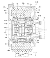
- FIG. 1 is a front sectional view showing a wheel drive device 10 according to the first embodiment.
- the wheel drive device 10 of the present embodiment is assembled to the vehicle body 12 of the transport carriage and used for driving the tire 28 of the transport carriage.
- the transport carriage of this embodiment is a tracked carriage, and the tire 28 of this embodiment travels on the travel surface 16a of the rail 16 laid on the floor surface.
- the direction along the rotation center line La of the tire 28 is defined as the axial direction X of the wheel drive device 10.
- the circumferential direction and the radial direction of a circle centered on the rotation center line La are simply referred to as “circumferential direction” and “radial direction”.
- the wheel drive device 10 mainly includes a speed reduction mechanism 18, carriers 20 and 22, an output member 24, a baseband 26, and a tire 28.
- the deceleration mechanism 18 can decelerate the rotation transmitted from the drive source.
- the drive source in the present embodiment is a motor, but is not limited thereto, and may be a gear motor, an engine, or the like in which the motor and the speed reducer are integrated.
- the speed reduction mechanism 18 of the present embodiment is an eccentric oscillating speed reduction mechanism.
- the speed reduction mechanism 18 mainly includes an input shaft 30, an eccentric body 32, an external gear 34, an eccentric body bearing 36, and an internal gear 38.
- the input shaft 30 is connected to an output shaft 40 of a drive source that protrudes outward from the vehicle body 12 in the vehicle width direction, and receives rotation output from the output shaft 40.
- the eccentric body 32 is provided to be rotatable integrally with the input shaft 30.
- a plurality of eccentric bodies 32 are provided at intervals in the axial direction X.
- the external gear 34 is individually provided corresponding to each of the plurality of eccentric bodies 32.
- the external gear 34 is supported by the corresponding eccentric body 32 via the eccentric body bearing 36.
- the external gear 34 is swung by the corresponding eccentric body 32 so that its own axis rotates around the rotation center line La.
- the external gear 34 is in mesh with the internal gear 38.
- the internal gear 38 of the present embodiment has a plurality of outer pins 38a supported on the inner peripheral portion of the output member 24, and a plurality of outer rollers 38b rotatably supported on the plurality of outer pins 38a. .
- Each of the plurality of outer rollers 38 b constitutes an internal tooth of the internal gear 38.
- the number of internal teeth of the internal gear 38 (the number of external rollers 38b) is one more than the number of external teeth of the external gear 34 in this embodiment.
- the carriers 20 and 22 include an inner carrier 20 disposed on the vehicle body side from the external gear 34 and an outer carrier 22 disposed on the side opposite to the vehicle body from the external gear 34.
- vehicle body side refers to the vehicle body 12 side in the axial direction X
- anti-vehicle body side refers to the opposite side of the vehicle body 12 in the axial direction X.
- the carriers 20 and 22 are formed with a through hole 42 penetrating the central portion in the radial direction.
- An input shaft bearing 44 is disposed on the inner peripheral side of the through hole 42, and the carriers 20 and 22 support the input shaft 30 through the input shaft bearing 44 so as to be rotatable.
- the input shaft bearing 44 of this embodiment is a rolling bearing such as a ball bearing.
- the output member 24 has a cylindrical shape as a whole, and is configured using a metal such as a steel material. On the inner peripheral side of the output member 24, a speed reduction mechanism 18 and carriers 20, 22 are arranged. The output member 24 receives the rotation reduced by the reduction mechanism 18.
- the output member 24 of this embodiment also serves as a casing of the speed reduction mechanism 18, and an internal gear 38 of the speed reduction mechanism 18 is provided on the inner peripheral portion thereof.
- a main bearing 46 is disposed between the output member 24 and the carriers 20 and 22.
- the main bearing 46 of this embodiment is a rolling bearing such as a roller bearing.
- the carriers 20 and 22 are connected to the vehicle body 12 via a wheel cover 56 described later, and function as a support member that rotatably supports the output member 24 via a main bearing 46.
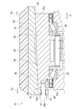
- FIG. 2 is an enlarged view of a part of FIG.
- the base band 26 is disposed on the outer peripheral side of the output member 24 and is externally fitted to the output member 24.
- the base band 26 has a cylindrical shape as a whole, and is configured using a metal such as a steel material. Open ends 48 are formed on both sides in the axial direction X on the inner peripheral portion of the baseband 26.
- the output member 24 is provided so as to fit inside the axial direction X from the opening end 48 of the baseband 26.
- the baseband 26 is integrated with the output member 24 by being externally fitted to the output member 24 by an interference fit.
- the tire 28 is attached to the outer periphery of the baseband 26 by adhesion or the like.
- the tire 28 is configured using a soft material that is softer than the baseband 26.
- the tire 28 is configured using an elastic body such as urethane rubber.
- the operation of the speed reduction mechanism 18 will be described.
- the rotation of the drive source is transmitted from the output shaft 40 to the input shaft 30 to the input shaft 30
- the input shaft 30 rotates.
- the rotation of the input shaft 30 is decelerated by the speed reduction mechanism 18 and transmitted to the output member 24.
- the tire 28 rotates on the traveling surface 16a by rotating the tire 28 together with the baseband 26 integrated with the output member 24.
- the eccentric body 32 rotates around the rotation center line La together with the input shaft 30.
- the eccentric body 32 rotates around the rotation center line La
- the external gear 34 swings so that the axis of the external gear 34 rotates around the rotation center line La.
- the meshing positions of the external gear 34 and the internal gear 38 are sequentially shifted.
- the internal gear 38 rotates relative to the external gear 34 by an amount corresponding to the difference in the number of teeth from the external gear 34, and the rotation component thereof. Is transmitted to the output member 24.
- the rotation of the input shaft 30 is decelerated at a reduction ratio corresponding to the difference in the number of teeth between the external gear 34 and the internal gear 38 and transmitted from the internal gear 38 to the output member 24.
- an outer peripheral tapered surface 50 is provided on the outer peripheral surface of the output member 24 of the present embodiment.
- an inner peripheral tapered surface 52 that is radially opposed to the outer peripheral tapered surface 50 of the output member 24 is provided.
- the outer peripheral taper surface 50 and the inner peripheral taper surface 52 are formed such that the outer diameter or the inner diameter decreases from one side in the axial direction X toward the other side.
- the outer peripheral tapered surface 50 and the inner peripheral tapered surface 52 of the present embodiment are formed so as to reduce in diameter from the vehicle body side (right side in FIG. 2) in the axial direction X toward the opposite vehicle body side (left side in FIG. 2).
- the direction in which the tapered surfaces 50 and 52 are reduced in diameter in the axial direction X is referred to as a reduced diameter direction Pa, and the direction in which the tapered surfaces 50 and 52 are increased in diameter is referred to as an enlarged diameter direction Pb.
- the outer peripheral taper surface 50 and the inner peripheral taper surface 52 are linear tapers whose diameters change linearly (linearly) with respect to a change in distance in the axial direction X.
- the taper rate of the outer peripheral taper surface 50 and the inner peripheral taper surface 52 is set to the same size.
- the taper rate means a rate of change in diameter with respect to a change in distance in the axial direction X.
- the inner peripheral tapered surface 52 is set to have a larger axial dimension than the outer peripheral tapered surface 50.
- the axial dimension refers to a dimension along the axial direction X. Note that “same” in this specification includes not only completely the same case but also almost the same case.
- the base band 26 is externally fitted to the output member 24 by an interference fit with the tapered surfaces 50 and 52 in contact with the output member 24. This means that the output member 24 and the base band 26 are fitted around the output member 24 with a margin in the radial direction. It can be understood that the base band 26 is externally fitted to the output member 24 in a state where the output member 24 and the base band 26 are elastically deformed in the radial direction. By the fitting using the interference fitting, the base band 26 is integrated with the output member 24 with the tapered surfaces 50 and 52 being in close contact with the output member 24.
- the base band 26 is provided so as to be positioned on the outer side in the axial direction X from the end surface portions 24a on both sides in the axial direction of the output member 24. That is, the output member 24 is covered from the radially outer side by the base band 26 over the entire length in the axial direction X.
- the base band 26 has a flange portion 26a extending from the one end portion (the end portion having a smaller inner diameter) on the diameter reducing direction Pa side to the radially inner peripheral side.
- the flange portion 26 a of the baseband 26 is disposed at a position that overlaps with the end surface portion 24 a on the diameter reducing direction Pa side of the output member 24 when viewed from the axial direction X.
- the flange portion 26a of the baseband 26 and the end surface portion 24a on the diameter reducing direction Pa side of the output member 24 are fastened by a bolt B1.
- the shaft portion of the bolt B1 is inserted into the insertion hole 26b formed in the flange portion 26a and screwed into the female screw hole 24b formed in the end surface portion 24a of the output member 24.
- a gap 54 is formed between the flange portion 26 a of the baseband 26 and the end surface portion 24 a of the output member 24.
- the baseband 26 is externally fitted to the output member 24 by interference fitting as described above. Therefore, it is possible to suppress the relative displacement between the inner circumferential tapered surface 52 and the outer circumferential tapered surface 50 due to the slight vibration, and it is possible to prevent the occurrence of fretting wear due to the relative displacement.
- the baseband 26 of this embodiment is externally fitted to the output member 24 with the tapered surfaces 50 and 52 in contact with the output member 24. Therefore, by applying the tightening force in the axial direction X to the base band 26 and the output member 24 in a state where the outer peripheral tapered surface 50 of the output member 24 is disposed on the inner peripheral side of the inner peripheral tapered surface 52 of the base band 26.
- the state where the baseband 26 and the output member 24 are tightly fitted can be easily realized. For this reason, the assembling property of the base band to the output member 24 is good.
- the tightening force in the axial direction X refers to a force applied in a direction in which the output member 24 and the baseband 26 are brought closer to each other in the axial direction X.
- the fastening allowance in the radial direction of the base band 26 and the output member 24 can be adjusted. Therefore, it is possible to easily secure the necessary tightening allowance required for preventing fretting wear through adjustment of the tightening force applied to the base band 26 and the output member 24. Together, the wheel drive device 10 of the present embodiment can effectively take measures against fretting wear.
- the flange portion 26a of the base band 26 and the end surface portion 24a of the output member 24 are fastened by a bolt B1. Therefore, the tightening force in the axial direction X between the baseband 26 and the output member 24 can be managed through a simple method such as management of the tightening torque of the bolt B1, and the necessary tightening allowance required for preventing fretting wear can be easily achieved. It can be secured.
- the tightening torque of the bolt B1 can be managed using a torque wrench or the like.
- a gap 54 is formed between the flange portion 26 a of the baseband 26 and the end surface portion 24 a of the output member 24.
- the axial dimension of the gap 54 decreases as the interference between the baseband 26 and the output member 24 increases. Therefore, the tightening allowance between the baseband 26 and the output member 24 can be easily grasped through visual management of the axial dimension of the gap 54.
- the tightening force in the axial direction X (hereinafter also simply referred to as “tightening force”) applied to the output member 24 and the baseband 26 may be set to satisfy the following condition. This can also be said to be set so as to satisfy the following condition with respect to the tightening margin in the radial direction of the output member 24 and the baseband 26, or the tightening torque of the bolt B1.
- a load applied to the base band 26 and necessary for the base band 26 to start rotating is referred to as a starting load [kgf] of the base band 26.
- the tightening force of the base band 26 and the like is preferably set so that the starting load of the base band 26 is 4 kgf or more and 10 kgf or less under the condition that the power transmission path of the speed reduction mechanism 18 and the drive source is disconnected.
- This numerical condition is set based on the results of experimental studies by the present inventors.
- the reason why the power transmission path between the speed reduction mechanism 18 and the drive source is disconnected is to exclude the rotational resistance of the drive source in consideration of the starting load of the baseband 26.
- the separation of the power transmission path is realized by removing the input shaft 30 of the speed reduction mechanism 18 from the output shaft 40 of the drive source.
- the tightening force that satisfies the above-described starting load range is set by managing the tightening torque of the bolt B1.
- the “pair of bearings” here refers to, for example, a main bearing 46 on the vehicle body side and a main bearing 46 on the side opposite to the vehicle body.
- the rotating body includes the external gear 34, the internal gear 38, the main bearing 46, and the like.
- the interference fit between the baseband 26 and the output member 24 can be realized while preventing the no-load characteristic of the speed reduction mechanism 18 and the adverse effect on the bearing.
- the method for measuring the starting load of the baseband 26 will be described. First, the push-pull gauge is attached to the end surface portion in the axial direction X of the base band 26 on the side where the flange portion 26a is located. Next, the end surface portion 24a of the baseband 26 is pulled through a push-pull gauge in a tangential direction of a circle centered on the rotation axis La of the tire 28. At this time, the tire 28 is separated from the traveling surface 16a so that no load is applied to the tire 28. When the base band 26 starts to rotate, the maximum tensile load measured by the push-pull gauge from the start of pulling the push-pull gauge to the start of rotation of the base band 26 is taken as the starting load of the base band 26.
- the wheel drive device 10 of the present embodiment includes a loosening prevention mechanism 55 for restricting the looseness of the bolt B1.
- the locking mechanism 55 of the present embodiment is a locking lock washer that is interposed between the head of the bolt B1 and the flange portion 26a of the baseband 26. Thereby, the secular change of the fastening force of the bolt B1 can be prevented, and the starting load of the baseband 26 can be ensured over a long period of time.
- the locking mechanism 55 may be a locking bolt or the like.
- the wheel drive device 10 includes a wheel cover 56 that covers the baseband 26 and the tire 28.
- the wheel cover 56 is formed with an opening 56a from which the baseband 26 and the tire 28 protrude downward.
- the wheel cover 56 includes an inner cover member 58 that is assembled to the vehicle body 12 with bolts (not shown), and an outer cover member 60 that is detachably attached to the inner cover member 58 with bolts (not shown).
- the inner cover member 58 has an inner side cover portion 58a that covers the baseband 26 and the tire 28 from the diameter-enlarging direction Pb in the axial direction X.
- the inner carrier 20 is fixed to the inner side cover portion 58a with a carrier bolt B3.
- the inner cover member 58 of the present embodiment has an outer peripheral cover portion 58b that covers the tire 28 and the baseband 26 from the outer peripheral side.
- the outer cover member 60 has an outer side cover portion 60a that covers the tire 28 and the baseband 26 from the reduced diameter direction Pa in the axial direction X.
- the outer carrier 22 is fixed to the outer side cover portion 60a by fitting.
- the outer cover member 60 can be detached from the inner cover member 58 while the wheel drive device 10 is assembled to the vehicle body 12. Further, when the outer cover member 60 is removed from the inner cover member 58, the bolt B ⁇ b> 1 can be attached to and detached from the output member 24 and the baseband 26 while the wheel drive device 10 is attached to the vehicle body 12. Further, when the bolt B ⁇ b> 1 is removed from the output member 24 and the base band 26, the base band 26 can be attached to and detached from the output member 24 while the wheel drive device 10 is attached to the vehicle body 12.
- a storage space 62 for storing the speed reduction mechanism 18 is formed on the inner peripheral side of the output member 24.
- the storage space 62 is sealed using a plurality of sealing members 64a to 64d.
- a lubricant (not shown) is sealed in the storage space 62 sealed with the sealing members 64a to 64d.
- the sealing members 64 a to 64 d include an outer peripheral oil seal 64 a interposed between the output member 24 and the carriers 20, 22, a seal cap 64 b that closes the through hole 42 of the outer carrier 22, and a penetration of the inner carrier 20.
- a shaft cover 64c for closing the hole 42 and an inner peripheral oil seal 64d are included.
- the outer peripheral side oil seal 64 a is disposed between the output member 24 and the carriers 20 and 22 at a location closer to the outer space than the main bearing 46.
- the shaft cover 64 c is disposed closer to the vehicle body than the input shaft bearing 44, and the input shaft 30 penetrates in the axial direction X.
- the inner peripheral oil seal 64d is interposed between the shaft cover 64c and the input shaft 30.
- the sealing members 64a to 64d are arranged between the output member 24 and the carriers 20 and 22 or on the inner peripheral side of the through holes 42 of the carriers 20 and 22, and between the carriers 20 and 22 and the wheel cover 56. Is not placed. Therefore, when the outer cover member 60 of the wheel cover 56 is removed from the inner cover member 58, the storage space 62 on the inner peripheral side of the output member 24 can be maintained sealed by the sealing members 64a to 64d. As a result, the tire 28 can be replaced without disassembling the speed reduction mechanism 18 and taking in and out the lubricant.
- the invention of the series (product group) of the wheel drive device 10 described below is regarded as the invention of the manufacturing method of the series of the wheel drive device 10 and the invention of the design method (construction method) of the series of the wheel drive device 10. You can also.
- the outer diameter of the tire 28 of the wheel drive device 10 can be various sizes according to a request from a delivery destination of the wheel drive device 10. As described above, it is desired to share the management items as much as possible from the viewpoint of reducing the management effort between the plurality of wheel drive devices 10 having the different outer diameters of the tires 28.
- the series of the wheel drive device 10 of the present embodiment is made under such a background.
- the wheel drive device series includes a first wheel drive device 10-A and a second wheel drive device 10-B.
- the first wheel drive device 10-A is the wheel drive device described with reference to FIGS.
- FIG. 3 is a front sectional view of the second wheel drive device 10-B.
- the second wheel drive device 10-B includes the same components in many respects as the first wheel drive device 10-A.
- the same components in the first wheel drive device 10-A and the second wheel drive device 10-B will be described using the same names.
- the second wheel drive device 10-B mainly includes a second reduction mechanism 18-B, second carriers 20-B and 22-B, a second output member 24-B, and a second baseband 26-B. And a second tire 28-B.
- Each of the second reduction mechanism 18-B and the second carriers 20-B and 22-B includes the first reduction mechanism 18-A and the first carriers 20-A and 22-A of the first wheel drive device 10-A.
- common refers to the components of the hardware elements (here, the speed reduction mechanism and the carrier) referred to between the first wheel drive device 10-A and the second wheel drive device 10-B. This means that the shape and dimensions are the same as well as the material of the component.
- the second wheel drive device 10-B other internal parts arranged on the inner peripheral side of the second output member 24-B are also other internal parts arranged on the inner peripheral side of the first output member 24-A. What is in common with is used.
- the other internal parts here are the input shaft bearing 44, the main bearing 46, oil seals 64a and 64d, a seal cap 64b, a shaft cover 64c, and the like. Thereby, the number of parts to be managed can be reduced between the first wheel drive device 10-A and the second wheel drive device 10-B.
- FIG. 4 (a) is an enlarged view of a part of the first wheel drive device 10-A
- FIG. 4 (b) is an enlarged view of a part of the second wheel drive device 10-B
- the second output member 24-B is thicker than the first output member 24-A in the entire range in the axial direction X.
- the thickness here refers to a dimension along the radial direction.
- the second output member 24-B and the first output member 24-A have the same inner peripheral portion and outer peripheral portion in shape and axial dimension.
- the first output member 24-A and the second output member 24-B have the same inner peripheral shape and axial dimensions because the taper rate and the axial dimension of the outer peripheral tapered surface 50 are the same. It also means that.
- the inner peripheral portion of the second output member 24-B has the same radial dimension as the first output member 24-A. Further, the second output member 24-B and the first output member 24-A have the same overall axial dimensions and materials.
- “the shape is the same” means that the contours at the cut surface along the axial direction A are the same.
- the second baseband 26-B is thicker than the first baseband 26-A in the entire range in the axial direction X. Further, the second baseband 26-B and the first baseband 26-A have the same inner peripheral portion and outer peripheral portion in shape and axial dimension. The shape and axial dimension of the inner peripheral portion of the first baseband 26-A and the second baseband 26-B are the same because the taper ratio and axial dimension of the inner peripheral tapered surface 52 are the same. It is also the same.
- the second output member 24-B has the same overall axial dimensions and materials as the first output member 24-A.
- the second tire 28-B has a larger outer diameter than the first tire 28-A.
- the second tire 28-B has the same thickness as the first tire 28 in order to match the running resistance with the first tire 28. Further, the second tire 28-B has the same overall shape, axial dimension and material as the first tire 28.
- the second baseband 26-B is set so that the outer diameter of the second baseband 26-B increases with the increase in the outer diameter of the second tire 28-B of the second wheel drive device 10-B.
- the second base 28-B and the first tire 28-A have the same thickness so that the outer diameter of the second baseband 26-B increases in this way. The thickness of the band 26-B is increased.
- the output member is also shared among the plurality of wheel drive devices, only the thickness of the second baseband 26-B is increased, and the second output member 24-B is combined with the first output member 24-A. It will be the same thickness. At this time, the rigidity of the second base band 26-B is increased compared to the first base band 26-A, while the rigidity of the first output member 24-A and the second output member 24-B is the same.
- the first baseband 26-B when a predetermined range of tightening force with which the first wheel drive device 10-A can obtain a required starting load is also applied to the second baseband 26-B of the second wheel drive device 10-B, etc.
- the present inventor has obtained the knowledge that this phenomenon occurs.
- the first baseband 26-B when a tightening force in the same predetermined range as that of the first wheel drive device 10-A is applied, the first baseband 26-B causes the first baseband 26-B to increase in rigidity. There is a tendency that the amount of deformation toward the outer peripheral side in the radial direction with respect to the base band 26-A decreases.
- the second output member 24-B As the amount of deformation of the second baseband 26-B from the first baseband 26-A decreases, the second output member 24-B moves further radially inward than the first output member 24-A. The amount of deformation tends to increase. As a result, when the same predetermined range of tightening force as that of the first wheel drive device 10-A is also applied to the second baseband 26-B and the second output member 24-B, the first baseband 26-A is more 2 The starting load of the baseband 26-B increases excessively, and the required starting load of the baseband 26 may not be obtained.
- the first output member 24 is set in accordance with the thickness of the second baseband 26-B being larger than that of the first baseband 26-A.
- the thickness of the second output member 24-B is larger than that of -A.
- the present inventor further examined this problem, and obtained the knowledge that the balance of rigidity between the output member 24 and the baseband 26 is important. That is, when the rigidity of the second baseband 26-B is increased more than that of the first baseband 26-A, the deformation amount of the second output member 24-B is suppressed from increasing compared to the first output member 24-A. Accordingly, it is important to increase the rigidity of the second output member 24-B in a well-balanced manner in accordance with the increase in the rigidity of the second baseband 26-B.
- the second output member 24-B has the same shape as the first output member 24-A in the inner peripheral portion and the outer peripheral portion. Further, the second baseband 26-B has the same shape as the first baseband 26-A in the inner peripheral portion and the outer peripheral portion. This is because the rigidity of the output member 24 and the baseband 26 cannot be balanced if these shapes are changed between the first wheel driving device 10-A and the second wheel driving device 10-B.
- the thickness of the minimum outer diameter portion 24c where the outer peripheral tapered surface 50 of the output member 24 becomes the minimum diameter is set to tb1 [mm].
- the thickness of the maximum outer diameter portion 24d having the maximum outer diameter tapered surface 50 of the output member 24 is defined as tb2 [mm].
- the thickness of the small inner diameter portion 26c of the base band 26 whose position in the axial direction X coincides with the minimum outer diameter portion 24c of the output member 24 is defined as ta1 [mm].
- the thickness of the large inner diameter portion 26d of the baseband 26 whose position in the axial direction X coincides with the maximum outer diameter portion 24d of the output member 24 is defined as ta2.
- the thickness tb1 of the minimum outer diameter portion 24c of the output member 24 is set to 1.1 to 1.2 times the thickness ta1 of the small inner diameter portion 26c of the baseband 26.
- the thickness tb2 of the maximum outer diameter portion 24d of the output member 24 is set to be 1.5 times or more and 2.0 times or less of the thickness ta2 of the large inner diameter portion 26d of the baseband 26.
- This numerical condition is set based on the results of experimental studies by the present inventors. This condition is set so as to satisfy both the first wheel driving device 10-A and the second wheel driving device 10-B individually.
- the second output from the first output member 24-A is within the range corresponding to the thickness of the second baseband 26-B.
- the rigidity of the output member 24 and the baseband 26 is balanced.
- the output is compared with the baseband 26.
- the rigidity of the member 24 becomes excessively small.
- the radial direction of the output member 24 of the wheel driving device 10 that does not satisfy this condition
- the amount of deformation becomes excessively large and the required starting load cannot be obtained.
- the thickness tb2 of the output member 24 of either the first wheel driving device 10-A or the second wheel driving device 10-B is less than 1.5 times the thickness ta2 of the baseband 26.
- the output is compared with the baseband 26.
- the rigidity of the member 24 becomes excessively large.
- the radial direction of the output member 24 of the wheel driving device 10 that does not satisfy this condition There is a possibility that the amount of deformation becomes excessively small and the required starting load cannot be obtained.
- the thickness tb2 of the output member 24 of either the first wheel driving device 10-A or the second wheel driving device 10-B is more than 2.0 times the thickness ta2 of the baseband 26.
- the shapes of the inner peripheral portion and the outer peripheral portion of the baseband 26 and the output member 24 are the same, and the second wheel having the same speed reduction mechanism 18 is used. Even if the thickness of the baseband 26 is changed with respect to the drive device 10-B, the range of the tightening force necessary to obtain a required starting load can be shared.
- FIG. 5 is an enlarged cross-sectional view showing a part of the wheel drive device 10 of the second embodiment.
- At least one of the outer peripheral tapered surface 50 of the output member 24 and the inner peripheral tapered surface 52 of the baseband 26 is formed with a groove 66 at a position facing each other in the radial direction.
- the groove portion 66 of this embodiment is formed on the inner peripheral tapered surface 52 of the baseband 26.
- the groove portion 66 forms a closed space closed with respect to the external space between the outer peripheral tapered surface 50 of the output member 24 and the inner peripheral tapered surface 52 of the base band 26.
- the groove portions 66 are provided so as to be located on the inner side in the axial direction with respect to the end surface portions 24 a on both sides in the axial direction of the output member 24.
- the groove part 66 of this embodiment is formed so that it may continue cyclically
- the outer peripheral tapered surface 50 and the inner peripheral tapered surface 52 are required to be in uniform contact over a wide range so that a large load is not locally applied between the contact points.
- the groove portion 66 as described above is formed, the contact portions of each other in the radially opposing region between the outer peripheral tapered surface 50 and the inner peripheral tapered surface 52 are provided. Can be reduced. Therefore, it is possible to reduce the range in which the accuracy should be ensured when the outer peripheral taper surface 50 and the inner peripheral taper surface 52 are in uniform contact with each other. It can be easily realized.
- the inner surface of the groove 66 formed on one of the outer peripheral tapered surface 50 and the inner peripheral tapered surface 52 does not contact the other of them, it is not necessary to ensure accuracy. Therefore, it is not necessary to perform surface processing on the inner surface of the groove 66 when performing surface processing for smoothing the tapered surfaces 50 and 52 of the molded product obtained by molding such as casting. For this reason, the time required for surface processing of the tapered surfaces 50 and 52 can be shortened, and the manufacturing cost can be reduced.
- the groove 66 may be formed on the outer peripheral tapered surface 50 of the output member 24. Further, the groove 66 may be formed on both the outer peripheral tapered surface 50 of the output member 24 and the inner peripheral tapered surface 52 of the base band 26. The groove part 66 may be formed over a part of the range rather than the entire circumference in the circumferential direction.
- the wheel drive device 10 has been described as being incorporated into a transport cart, the assembly partner is not particularly limited. Moreover, although this conveyance trolley demonstrated the tracked trolley as an example, a trackless trolley
- the deceleration mechanism 18 has been described by taking an eccentric oscillating deceleration mechanism as an example, but the type thereof is not particularly limited.
- any of a planetary gear mechanism, a parallel shaft gear mechanism, an orthogonal shaft gear speed reduction mechanism, a flexure meshing speed reduction mechanism, and the like may be included.
- the eccentric oscillating speed reduction mechanism in addition to the center crank type in which the input shaft (eccentric body shaft) is disposed at the axis of the internal gear, a plurality of positions are offset from the axis of the internal gear.
- a sorting type in which an input shaft (eccentric body shaft) is arranged may be used.
- the present invention is not limited to this.
- the output member 24 may be disposed on the outer peripheral side of the casing of the speed reduction mechanism 18 and may be configured to be rotated by the output shaft of the speed reduction mechanism 18.
- the tires 28 have the same thickness between the first wheel drive devices 10-A and 10-B. From the viewpoint of obtaining the effect (A) described above, the thickness of the second baseband 26-B is larger than that of the first baseband 26-A, and the second output member 24-B is more than the first output member 24-A. It suffices to satisfy the condition that the thickness of the material increases.
- the present invention relates to a wheel drive device.
Landscapes
- Engineering & Computer Science (AREA)
- Chemical & Material Sciences (AREA)
- Combustion & Propulsion (AREA)
- Transportation (AREA)
- Mechanical Engineering (AREA)
- Arrangement Or Mounting Of Propulsion Units For Vehicles (AREA)
- Rolling Contact Bearings (AREA)
Abstract
駆動源から伝達される回転を減速する減速機構と、減速機構で減速された回転が伝達される筒状の出力部材24と、出力部材24に外嵌されるベースバンド26と、ベースバンド26に取り付けられるタイヤ28と、を備える車輪駆動装置であって、出力部材24の外周面とベースバンド26の内周面とにはテーパ面50、52が設けられ、ベースバンド26は、出力部材24との間で互いのテーパ面50、52を接触させた状態で締まり嵌めにより出力部材24に外嵌される。
Description
本発明は、車輪駆動装置及び車輪駆動装置のシリーズに関する。
従来より、搬送台車等の車輪を駆動する車輪駆動装置として、減速機構が内部に組み込まれたものが知られている。たとえば、特許文献1には、減速機構から回転が伝達される回転体と、その回転体の外周側に嵌められたタイヤとを備える車輪駆動装置が開示されている。
特許文献1の車輪駆動装置では、回転体の外周面に軸方向に平行な階段状の嵌着面を設け、その嵌着面の外側にタイヤのホイールを嵌めた構造を採用している。本発明者が検討したところ、この構造では、回転体の嵌着面とホイールとの間でフレッティング摩耗が生じ易くなるという知見を得た。フレッティング摩耗は不具合の原因となるため、その対策が望まれる。
本発明のある態様は、こうした状況に鑑みてなされ、その目的の1つは、フレッティング摩耗への対策を図れる車輪駆動装置を提供することにある。
本発明のある態様は車輪駆動装置に関し、駆動源から伝達される回転を減速する減速機構と、前記減速機構で減速された回転が伝達される筒状の出力部材と、前記出力部材に外嵌されるベースバンドと、前記ベースバンドに取り付けられるタイヤと、を備える車輪駆動装置であって、前記出力部材の外周面と前記ベースバンドの内周面とにはテーパ面が設けられ、前記ベースバンドは、前記出力部材との間で互いのテーパ面を接触させた状態で締まり嵌めにより前記出力部材に外嵌される。
本発明によれば、フレッティング摩耗への対策を図れる車輪駆動装置を提供できる。
以下、実施形態、変形例では、同一の構成要素に同一の符号を付し、重複する説明を省略する。また、各図面では、説明の便宜のため、構成要素の一部を適宜省略したり、構成要素の寸法を適宜拡大、縮小して示す。
まず、本実施形態の車輪駆動装置を想到するに到った背景から説明する。本実施形態の車輪駆動装置は、減速機構の回転が伝達される筒状の出力部材と、出力部材に外嵌されるベースバンドと、ベースバンドに取り付けられるタイヤとを備える。この種の車輪駆動装置において、出力部材とベースバンドの接触面でフィッティング摩耗が生じてしまうと、摩耗粉により周辺環境の汚損を招く。これは、クリーンルーム等のクリーン性が要求される環境下で車輪駆動装置を用いる場合に問題となる。
また、この種の車輪駆動装置では、タイヤが経年的に摩耗するため、タイヤの交換を目的として、出力部材からベースバンドを取り外す場合がある。この場合に、出力部材とベースバンドの接触面でフィッティング摩耗が生じてしまうと、摩耗粉により出力部材とベースバンドが固着してしまい、出力部材からベースバンドを取り外し不能になり得る。
このように、出力部材とベースバンドの間で生じるフィッティング摩耗は不具合の原因となる。この対策として、本実施形態の車輪駆動装置では、締まり嵌めにより出力部材にベースバンドを外嵌させている。これにより、ベースバンドや出力部材が微振動したときでも、両者の接触面を密着させた状態を維持できる。よって、この微振動に伴う接触面の相対変位を抑制でき、その相対変位に伴うフレッティング摩耗の発生を防止できる。
また、本実施形態の車輪駆動装置では、ベースバンドと出力部材にテーパ面を設け、互いのテーパ面を接触させた状態で出力部材にベースバンドを外嵌させている。これにより、出力部材に対するベースバンドの組み付け性を良好にしつつ、十分な締め代を持った締まり嵌めを実現でき、フレッティング摩耗への対策を効果的に図れる。以下、この車輪駆動装置の詳細を説明する。
(第1の実施の形態)
図1は、第1実施形態の車輪駆動装置10を示す正面断面図である。本実施形態の車輪駆動装置10は、搬送台車の車体12に組み付けられ、搬送台車のタイヤ28の駆動に用いられる。本実施形態の搬送台車は有軌道台車であり、本実施形態のタイヤ28は床面に敷設されたレール16の走行面16a上を走行する。以下、タイヤ28の回転中心線Laに沿った方向を車輪駆動装置10の軸方向Xとする。また、その回転中心線Laを中心とする円の円周方向、半径方向を、単に「周方向」、「径方向」とする。
図1は、第1実施形態の車輪駆動装置10を示す正面断面図である。本実施形態の車輪駆動装置10は、搬送台車の車体12に組み付けられ、搬送台車のタイヤ28の駆動に用いられる。本実施形態の搬送台車は有軌道台車であり、本実施形態のタイヤ28は床面に敷設されたレール16の走行面16a上を走行する。以下、タイヤ28の回転中心線Laに沿った方向を車輪駆動装置10の軸方向Xとする。また、その回転中心線Laを中心とする円の円周方向、半径方向を、単に「周方向」、「径方向」とする。
車輪駆動装置10は、主に、減速機構18と、キャリア20、22と、出力部材24と、ベースバンド26と、タイヤ28とを備える。
減速機構18は、駆動源から伝達される回転を減速可能である。本実施形態での駆動源は、モータであるが、これに限定されず、モータと減速装置が一体化されたギヤモータ、エンジン等でもよい。本実施形態の減速機構18は偏心揺動型減速機構である。減速機構18は、主に、入力軸30と、偏心体32と、外歯歯車34と、偏心体軸受36と、内歯歯車38とを有する。
入力軸30には、車体12から車幅方向外側に突出する駆動源の出力軸40が接続され、その出力軸40から出力される回転が入力される。
偏心体32は、入力軸30と一体的に回転可能に設けられる。偏心体32は、軸方向Xに間を置いて複数設けられる。
外歯歯車34は、複数の偏心体32のそれぞれに対応して個別に設けられる。外歯歯車34は、偏心体軸受36を介して対応する偏心体32に支持される。外歯歯車34は、対応する偏心体32によって、自らの軸心が回転中心線La周りを回転するように揺動させられる。
内歯歯車38には、外歯歯車34が内接噛合している。本実施形態の内歯歯車38は、出力部材24の内周部に支持される複数の外ピン38aと、複数の外ピン38aのそれぞれに回転自在に支持される複数の外ローラ38bとを有する。複数の外ローラ38bのそれぞれは内歯歯車38の内歯を構成する。内歯歯車38の内歯数(外ローラ38bの数)は、本実施形態において、外歯歯車34の外歯数より一つ多い。
キャリア20、22には、外歯歯車34より車体側に配置される内側キャリア20と、外歯歯車34より反車体側に配置される外側キャリア22とが含まれる。本明細書での車体側とは軸方向Xの車体12側をいい、反車体側とは車体12とは軸方向Xの反対側をいう。
キャリア20、22には径方向の中央部を貫通する貫通穴42が形成される。貫通穴42の内周側には入力軸軸受44が配置され、キャリア20、22は入力軸軸受44を介して入力軸30を回転自在に支持する。本実施形態の入力軸軸受44は玉軸受等の転がり軸受けである。
出力部材24は、全体として筒状をなし、鋼材等の金属を用いて構成される。出力部材24の内周側には、減速機構18やキャリア20、22が配置される。出力部材24には、減速機構18で減速された回転が伝達される。本実施形態の出力部材24は、減速機構18のケーシングを兼ねており、その内周部には減速機構18の内歯歯車38が設けられる。
出力部材24とキャリア20、22の間には主軸受46が配置される。本実施形態の主軸受46は、ローラ軸受等の転がり軸受けである。キャリア20、22は、後述する車輪カバー56を介して車体12に接続され、主軸受46を介して出力部材24を回転自在に支持する支持部材として機能する。
図2は、図1の一部の拡大図である。ベースバンド26は、出力部材24の外周側に配置され、出力部材24に外嵌される。ベースバンド26は、全体として筒状をなし、鋼材等の金属を用いて構成される。ベースバンド26の内周部には軸方向Xの両側に開口端48が形成される。出力部材24は、ベースバンド26の開口端48より軸方向Xの内側に収まるように設けられる。ベースバンド26は、後述のように、締まり嵌めにより出力部材24に外嵌されることで出力部材24と一体化される。
タイヤ28は、ベースバンド26の外周部に接着等により取り付けられる。タイヤ28は、ベースバンド26より軟質な軟質素材を用いて構成される。この一例を挙げると、タイヤ28は、ウレタンゴム等の弾性体を用いて構成される。
以上の減速機構18の動作を説明する。駆動源の回転が出力軸40から入力軸30に伝達されると入力軸30が回転する。入力軸30が回転すると、入力軸30の回転が減速機構18で減速されて出力部材24に伝達される。出力部材24に減速機構18から回転が伝達されると、出力部材24に一体化されているベースバンド26とともにタイヤ28が回転することで、タイヤ28が走行面16a上を走行する。
本実施形態の減速機構18では、入力軸30が回転すると、入力軸30とともに偏心体32が回転中心線La周りに回転する。偏心体32がその回転中心線La周りに回転すると、外歯歯車34の軸心がその回転中心線La周りを回転するように外歯歯車34が揺動する。外歯歯車34が揺動すると、外歯歯車34と内歯歯車38の噛合位置が順次ずれる。この結果、内歯歯車38は、入力軸30が一回転する毎に、外歯歯車34との歯数差に相当する分、外歯歯車34に対して相対回転(自転)し、その自転成分を出力部材24に伝達する。このとき、入力軸30の回転は、外歯歯車34と内歯歯車38の歯数差に応じた減速比で減速されて、内歯歯車38から出力部材24に伝達される。
ここで、本実施形態の出力部材24の外周面には外周テーパ面50が設けられる。ベースバンド26の内周面には出力部材24の外周テーパ面50と径方向に対向する内周テーパ面52が設けられる。外周テーパ面50や内周テーパ面52は、軸方向Xの一方側から他方側に向かうにつれて外径又は内径が縮径するように形成される。本実施形態の外周テーパ面50や内周テーパ面52は、軸方向Xの車体側(図2中の右側)から反車体側(図2中の左側)に向かうにつれて縮径するように形成される。以下、軸方向Xのうちテーパ面50、52が縮径する方向を縮径方向Paといい、テーパ面50、52が拡径する方向を拡径方向Pbという。
外周テーパ面50と内周テーパ面52は、軸方向Xでの距離の変化に対して径が線形に(直線的に)変化する線形テーパである。外周テーパ面50と内周テーパ面52のテーパ率は同じ大きさに設定される。ここでのテーパ率とは、軸方向Xでの距離の変化に対する径の変化率を意味する。また、内周テーパ面52は、外周テーパ面50より軸方向寸法が大きくなるように設定される。ここでの軸方向寸法とは軸方向Xに沿った寸法をいう。なお、本明細書での「同じ」とは、完全に同じである場合の他に、ほぼ同じである場合も含まれる。
ベースバンド26は、出力部材24との間で互いのテーパ面50、52を接触させた状態で締まり嵌めにより出力部材24に外嵌されている。これは、出力部材24とベースバンド26が径方向での締め代を持ってベースバンド26が出力部材24に外嵌されていることを意味する。出力部材24とベースバンド26が径方向に弾性変形した状態でベースバンド26が出力部材24に外嵌されているとも捉えられる。この締まり嵌めを用いた嵌め合いにより、ベースバンド26は、出力部材24との間で互いのテーパ面50、52を密着させた状態で出力部材24に一体化される。
ベースバンド26は、出力部材24の軸方向両側の端面部24aより軸方向X外側に位置するように設けられる。つまり、出力部材24は、軸方向Xの全長に亘り、ベースバンド26により径方向外側から覆われる。ベースバンド26は、その縮径方向Pa側の一端部(内径が小さい方の端部)から径方向内周側に延在するフランジ部26aを有する。ベースバンド26のフランジ部26aは、出力部材24の縮径方向Pa側の端面部24aと軸方向Xから見たときに重なる位置に配置される。
ベースバンド26のフランジ部26aと出力部材24の縮径方向Pa側の端面部24aとはボルトB1により締結される。ボルトB1の軸部は、フランジ部26aに形成される挿通孔26bに挿通されるとともに、出力部材24の端面部24aに形成される雌ねじ孔24bにねじ込まれる。ベースバンド26のフランジ部26aと出力部材24の端面部24aの間には隙間54が形成される。
以上の車輪駆動装置10では、前述の通り、締まり嵌めによりベースバンド26を出力部材24に外嵌させている。よって、微振動に伴う内周テーパ面52と外周テーパ面50の相対変位を抑制でき、その相対変位に伴うフレッティング摩耗の発生を防止できる。
特許文献1の構造では、回転体とホイールの接触面が軸方向に平行である。よって、締まり嵌めによりホイールを回転体に外嵌するとなると、回転体の外径よりホイールの内径を小さくした状況のもと、回転体にホイールを組み付けることになり、ホイールの組み付け性に問題がある。また、特許文献1の構造のもとでは、回転体とホイールの締め代を事後的に調整できない。これらが相まって、良好な組み付け性を得つつフレッティング摩耗の防止に要する所要の締め代の確保が困難である。
これに対して、本実施形態のベースバンド26は、出力部材24との間で互いのテーパ面50、52を接触させた状態で出力部材24に外嵌される。よって、ベースバンド26の内周テーパ面52の内周側に出力部材24の外周テーパ面50を配置した状態で、ベースバンド26と出力部材24に軸方向Xでの締め付け力を付与することで、ベースバンド26と出力部材24が締まり嵌めされた状態を容易に実現できる。このため、出力部材24に対するベースバンドの組み付け性が良好である。なお、ここでの軸方向Xでの締め付け力とは、出力部材24とベースバンド26を軸方向Xで互いに近づける方向に付与される力をいう。
また、ベースバンド26と出力部材24に付与される軸方向Xでの締め付け力の大きさを調整することで、ベースバンド26と出力部材24の径方向での締め代を調整できる。よって、ベースバンド26と出力部材24に付与される締め付け力の調整を通じて、フレッティング摩耗の防止に要する所要の締め代を容易に確保できる。これらが相まって、本実施形態の車輪駆動装置10によれば、フレッティング摩耗への対策を効果的に図れる。
また、ベースバンド26のフランジ部26aと出力部材24の端面部24aとがボルトB1により締結されている。よって、ボルトB1の締め付けトルクの管理といった簡易な手法を通じてベースバンド26と出力部材24の間での軸方向Xでの締め付け力を管理でき、フレッティング摩耗の防止に要する所要の締め代を容易に確保できる。なお、ボルトB1の締め付けトルクは、トルクレンチ等を用いて管理できる。
また、ベースバンド26のフランジ部26aと出力部材24の端面部24aとの間には隙間54が形成されている。この隙間54の軸方向寸法は、ベースバンド26と出力部材24の間での締め代が大きくなるに従って減少する。よって、この隙間54の軸方向寸法の目視による管理を通じて、ベースバンド26と出力部材24の間での締め代を容易に把握できる。
ここで、出力部材24とベースバンド26に付与される軸方向Xの締め付け力(以下、単に「締め付け力」ともいう)は、次の条件を満たすように設定されていてもよい。これは、出力部材24とベースバンド26の径方向の締め代、あるいは、ボルトB1の締め付けトルクに関して、次の条件を満たすように設定していると言うこともできる。ベースバンド26に付与される荷重であって、ベースバンド26が回転し始めるために必要な荷重をベースバンド26の起動荷重[kgf]という。
このとき、ベースバンド26等の締め付け力は、減速機構18と駆動源の動力伝達経路を切り離した条件のもと、ベースバンド26の起動荷重が4kgf以上10kgf以下となるように設定されると好ましい。この数値条件は、本発明者の実験的な検討結果に基づき設定している。減速機構18と駆動源の間の動力伝達経路を切り離すのは、ベースバンド26の起動荷重を考慮するにあたり、駆動源の回転抵抗を除外するためである。この動力伝達経路の切り離しは、駆動源の出力軸40から減速機構18の入力軸30を取り外すことで実現される。本実施形態では、ボルトB1の締め付けトルクを管理することで、前述の起動荷重の範囲を満たす締め付け力に設定する。
ベースバンド26の起動荷重4kgf未満の場合、ベースバンド26等の締め付け力が不足し、出力部材24の締め代が不足する。これに伴い、出力部材24の内周側で軸方向Xに間を置いて配置される一対の軸受の両方に十分な予圧が付与されず、それら軸受の寿命の低下が懸念される。ここでの「一対の軸受」とは、本実施形態でいえば、たとえば、車体側の主軸受46と反車体側の主軸受46をいう。
ベースバンド26の起動荷重が10kgf超の場合、ベースバンド26等の締め付け力が過剰となり、出力部材24の締め代が過剰になる。これに伴い、減速機構18のバックラッシュが過度に小さくなったり、出力部材24の内周側に配置される軸受の予圧が過剰となり、回転体の回転抵抗が過度に大きくなる恐れがある。ここでの回転体とは、外歯歯車34、内歯歯車38、主軸受46等である。回転体の回転抵抗が過度に大きくなると、減速機構18に負荷を付与しない状況下での特性(以下、無負荷特性という)の大幅な変化が悪影響として懸念される。
ベースバンド26の起動荷重が前述の条件を満たしている場合、減速機構18の無負荷特性や軸受への悪影響の発生を防止しつつ、ベースバンド26と出力部材24の締まり嵌めを実現できる。
ベースバンド26の起動荷重の測定方法を説明する。まず、プッシュプルゲージをフランジ部26aがある側のベースバンド26の軸方向Xの端面部に取り付ける。次に、タイヤ28の回転軸線Laを中心とする円の接線方向に向かって、ベースバンド26の端面部24aをプッシュプルゲージを介して引っ張る。このとき、タイヤ28は走行面16aから離しておき、タイヤ28に負荷が付与されないようにする。ベースバンド26が回転し始めたら、プッシュプルゲージを引っ張り始めてからベースバンド26が回転し始めるまでの間でプッシュプルゲージにより測定された最大引張荷重をベースバンド26の起動荷重とする。
なお、本実施形態の車輪駆動装置10は、ボルトB1の緩みを規制するための緩み止め機構55を備える。本実施形態の緩み止め機構55は、ボルトB1の頭部とベースバンド26のフランジ部26aとの間に介装される緩み止めワッシャである。これにより、ボルトB1の締め付け力の経年的な変化を防止でき、ベースバンド26の起動荷重を長期に亘り確保できる。緩み止め機構55は、この他にも、緩み止めボルト等でもよい。
次に、車輪駆動装置10の他の特徴を説明する。
図1を参照する。車輪駆動装置10は、ベースバンド26やタイヤ28を覆う車輪カバー56を備える。車輪カバー56には、ベースバンド26やタイヤ28が下向きに突き出る開口部56aが形成される。車輪カバー56は、車体12に不図示のボルトにより組み付けられる内側カバー部材58と、不図示のボルトにより内側カバー部材58に着脱可能に取り付けられる外側カバー部材60とを有する。
図1を参照する。車輪駆動装置10は、ベースバンド26やタイヤ28を覆う車輪カバー56を備える。車輪カバー56には、ベースバンド26やタイヤ28が下向きに突き出る開口部56aが形成される。車輪カバー56は、車体12に不図示のボルトにより組み付けられる内側カバー部材58と、不図示のボルトにより内側カバー部材58に着脱可能に取り付けられる外側カバー部材60とを有する。
内側カバー部材58は、ベースバンド26やタイヤ28を軸方向Xの拡径方向Pbから覆う内側サイドカバー部58aを有する。内側サイドカバー部58aには、内側キャリア20がキャリアボルトB3により固定される。本実施形態の内側カバー部材58は、この他にも、タイヤ28やベースバンド26を外周側から覆う外周カバー部58bを有する。
外側カバー部材60は、タイヤ28やベースバンド26を軸方向Xの縮径方向Paから覆う外側サイドカバー部60aを有する。外側サイドカバー部60aには、外側キャリア22が嵌め合いにより固定される。
外側カバー部材60を内側カバー部材58から取り外した状態にあるとき、タイヤ28やベースバンド26に対して軸方向Xの縮径方向Paに車輪カバー56の一部が存在しない状況になる。よって、この状態にあるとき、タイヤ28やベースバンド26に対して縮径方向Paにある空間を作業空間として、タイヤ28やベースバンド26の交換作業をできる。
なお、外側カバー部材60は、車輪駆動装置10を車体12に組み付けた状態のまま、内側カバー部材58から取り外し可能である。また、内側カバー部材58から外側カバー部材60を取り外したとき、車輪駆動装置10を車体12に組み付けた状態のまま、出力部材24やベースバンド26に対してボルトB1を脱着可能である。また、出力部材24やベースバンド26からボルトB1を取り外したとき、車輪駆動装置10を車体12に組み付けた状態のまま、出力部材24に対してベースバンド26を脱着可能である。
出力部材24の内周側には減速機構18を収納する収納空間62が形成される。収納空間62は、複数の封止部材64a~64dを用いて封止される。この封止部材64a~64dで封止された収納空間62には潤滑剤(不図示)が封入される。
封止部材64a~64dには、出力部材24とキャリア20、22の間に介装される外周側オイルシール64aと、外側キャリア22の貫通穴42を塞ぐシールキャップ64bと、内側キャリア20の貫通穴42を塞ぐ軸カバー64c及び内周側オイルシール64dとが含まれる。外周側オイルシール64aは、出力部材24とキャリア20、22の間で主軸受46より外部空間寄りの箇所に配置される。軸カバー64cは、入力軸軸受44より車体側に配置され、入力軸30が軸方向Xに貫通している。内周側オイルシール64dは、軸カバー64cと入力軸30の間に介装される。
このように、封止部材64a~64dは、出力部材24とキャリア20、22の間やキャリア20、22の貫通穴42の内周側に配置され、キャリア20、22と車輪カバー56の間には配置されない。よって、車輪カバー56の外側カバー部材60を内側カバー部材58から取り外したとき、出力部材24の内周側の収納空間62が封止部材64a~64dにより封止された状態を維持できる。これにより、減速機構18の分解や潤滑剤の出し入れを伴うことなく、タイヤ28を交換できる。
次に、車輪駆動装置10のシリーズを説明する。なお、以下に説明する車輪駆動装置10のシリーズ(製品群)の発明は、車輪駆動装置10のシリーズの製造方法の発明や、車輪駆動装置10のシリーズの設計方法(構築方法)の発明と捉えることもできる。
車輪駆動装置10のタイヤ28の外径は、車輪駆動装置10の納入先からの要求等に応じて、様々な大きさになり得る。このようにタイヤ28の外径が異なる複数の車輪駆動装置10の間では、管理労力の削減を図る観点から、できる限り管理項目の共通化が望まれる。本実施形態の車輪駆動装置10のシリーズは、このような背景のもとでなされている。
車輪駆動装置のシリーズは、第1車輪駆動装置10-Aと、第2車輪駆動装置10-Bとを備える。第1車輪駆動装置10-Aは、図1、図2を用いて説明した車輪駆動装置である。図3は、第2車輪駆動装置10-Bの正面断面図である。第2車輪駆動装置10-Bは、第1車輪駆動装置10-Aと多くの点で同様の構成要素を備える。以下、第1車輪駆動装置10-Aと第2車輪駆動装置10-Bで同様の構成要素は同じ名称を用いて説明する。第1車輪駆動装置10-Aと第2車輪駆動装置10-Bで同様の構成要素を区別するときは、名称の冒頭に「第1、第2」と付し、符号の末尾に「-A、-B」と付すことで区別する。
第2車輪駆動装置10-Bは、主に、第2減速機構18-Bと、第2キャリア20-B、22-Bと、第2出力部材24-Bと、第2ベースバンド26-Bと、第2タイヤ28-Bとを備える。第2減速機構18-B、第2キャリア20-B、22-Bのそれぞれは、第1車輪駆動装置10-Aの第1減速機構18-A、第1キャリア20-A、22-Aと共通したものが用いられる。ここでの「共通」とは、第1車輪駆動装置10-Aと第2車輪駆動装置10-Bとの間で、言及しているハードウェア要素(ここでは減速機構、キャリア)の構成部品の形状、寸法は勿論のこと、その構成部品の素材も含めて同じであることを意味する。
第2車輪駆動装置10-Bは、第2出力部材24-Bの内周側に配置される他の内部部品も、第1出力部材24-Aの内周側に配置される他の内部部品と共通したものが用いられる。ここでの他の内部部品とは、入力軸軸受44、主軸受46、オイルシール64a、64d、シールキャップ64b、軸カバー64c等である。これにより、第1車輪駆動装置10-Aと第2車輪駆動装置10-Bとの間で、管理すべき部品点数を削減できる。
図4(a)は、第1車輪駆動装置10-Aの一部の拡大図であり、図4(b)は、第2車輪駆動装置10-Bの一部の拡大図である。第2出力部材24-Bは、軸方向Xの全範囲で第1出力部材24-Aより厚みが大きい。ここでの厚みとは径方向に沿った寸法をいう。また、第2出力部材24-Bは、第1出力部材24-Aとの間で、内周部及び外周部の形状及び軸方向寸法が同じである。第1出力部材24-Aと第2出力部材24-Bの内周部の形状及び軸方向寸法が同じであるというのは、これらの間で外周テーパ面50のテーパ率、軸方向寸法が同じであるということでもある。第2出力部材24-Bの内周部は、第1出力部材24-Aとの間で径方向寸法も同じである。また、第2出力部材24-Bは、第1出力部材24-Aとの間で全体の軸方向寸法や素材も同じである。ここでの「形状が同じ」とは、軸方向Aに沿った切断面での輪郭が同じであることを意味する。
第2ベースバンド26-Bは、軸方向Xの全範囲で第1ベースバンド26-Aより厚みが大きい。また、第2ベースバンド26-Bは、第1ベースバンド26-Aとの間で、内周部及び外周部の形状及び軸方向寸法が同じである。第1ベースバンド26-Aと第2ベースバンド26-Bの内周部の形状及び軸方向寸法が同じであるというのは、これらの間で内周テーパ面52のテーパ率、軸方向寸法が同じであるということでもある。また、第2出力部材24-Bは、第1出力部材24-Aとの間で全体の軸方向寸法や素材が同じである。
第2タイヤ28-Bは、第1タイヤ28-Aより大きい外径である。また、第2タイヤ28-Bは、第1タイヤ28と走行抵抗を合わせるため、第1タイヤ28と同じ厚みである。また、第2タイヤ28-Bは、第1タイヤ28との間で全体の形状及び軸方向寸法や素材が同じである。
ここで、前述の通り、減速機構18に関して所望の特性を得るためには、所要のベースバンド26の起動荷重を得られるように、ベースバンド26等の締め付け力の管理を要する。複数の車輪駆動装置の間で管理項目の共通化を図るうえでは、この締め付け力の共通化が望まれる。
このような背景のもと、前述のような、複数の車輪駆動装置の間で外径が異なるタイヤ28を用いる場合を考える。この場合に、第2車輪駆動装置10-Bの第2タイヤ28-Bの外径の増加に合わせて、第2ベースバンド26-Bの外径が増加するように第2ベースバンド26-Bの厚みを増加させるケースを考える。本実施形態では第2タイヤ28-Bと第1タイヤ28-Aで厚みを同じにしていることに合わせて、このように第2ベースバンド26-Bの外径が増加するように第2ベースバンド26-Bの厚みを増加させている。
このケースにおいて、複数の車輪駆動装置の間で出力部材も共通化するとなると、第2ベースバンド26-Bの厚みのみ増加させて、第2出力部材24-Bは第1出力部材24-Aと同じ厚みにすることになる。このとき、第1ベースバンド26-Aと比べて第2ベースバンド26-Bの剛性が増大する一方で、第1出力部材24-Aと第2出力部材24-Bの剛性が同じになる。
ここで、第1車輪駆動装置10-Aで所要の起動荷重を得られる所定の範囲の締め付け力を第2車輪駆動装置10-Bの第2ベースバンド26-B等にも付与した場合、次の現象が生じるという知見を本発明者は得た。まず、第2ベースバンド26-Bでは、第1車輪駆動装置10-Aと同じ所定の範囲の締め付け力を付与したとき、第2ベースバンド26-Bの剛性の増大に起因して、第1ベースバンド26-Aよりも径方向外周側への変形量が減少する傾向がある。一方、第2出力部材24-Bでは、第1ベースバンド26-Aからの第2ベースバンド26-Bの変形量の減少に伴い、第1出力部材24-Aよりも径方向内周側への変形量が大きくなる傾向がある。この結果、第1車輪駆動装置10-Aと同じ所定の範囲の締め付け力を第2ベースバンド26-Bや第2出力部材24-Bにも付与したとき、第1ベースバンド26-Aより第2ベースバンド26-Bの起動荷重が過度に増大してしまい、所要のベースバンド26の起動荷重を得られない恐れがある。
(A)そこで、本実施形態の第2車輪駆動装置10-Bでは、第1ベースバンド26-Aよりも第2ベースバンド26-Bの厚みを大きくしたことに合わせて、第1出力部材24-Aよりも第2出力部材24-Bの厚みを大きくしている。これにより、各車輪駆動装置10で同じ所定の範囲の締め付け力を付与したとき、第1出力部材24-Aと第2出力部材24-Bの厚みを同じにするときと比べ、第2出力部材24-Bの径方向内周側への変形量が過度に大きくなるのを抑制できる。この結果、各車輪駆動装置10で同じ所定の範囲の締め付け力を付与したとき、第1ベースバンド26-Aより第2ベースバンド26-Bの起動荷重が過度に増大することで、所要の起動荷重を得られない事態を避け易くなる。
ここで、本発明者は、この問題について更に検討したところ、出力部材24とベースバンド26の剛性のバランスが重要であるとの知見を得た。つまり、第2ベースバンド26-Bの剛性を第1ベースバンド26-Aより大きく増大させた場合、第1出力部材24-Aより第2出力部材24-Bの変形量が増大するのを抑えるべく、第2ベースバンド26-Bの剛性の増大に合わせてバランスよく第2出力部材24-Bの剛性を増大させることが重要となる。言い換えると、各車輪駆動装置10で出力部材24とベースバンド26の剛性のバランスがとれていれば、タイヤ28の外径の増加に合わせてベースバンド26の厚みを増大させたときでも、所要の起動荷重を得るために要する所定の範囲の締め付け力を各車輪駆動装置10で共用できる。本実施形態のシリーズでは、このような出力部材24とベースバンド26の剛性のバランスを複数の車輪駆動装置10の間でとるため、出力部材24とベースバンド26の肉厚比に関して、次の条件を規定している。
まず、前提として、第2出力部材24-Bは、第1出力部材24-Aと内周部及び外周部が同じ形状である。また、第2ベースバンド26-Bは、第1ベースバンド26-Aと内周部及び外周部の形状が同じである。これは、第1車輪駆動装置10-Aと第2車輪駆動装置10-Bの間で、これらの形状を変えると出力部材24とベースバンド26の剛性のバランスをとれなくなるためである。
次に、出力部材24の外周テーパ面50が最小径となる最小外径部24cの厚みをtb1[mm]とする。出力部材24の外周テーパ面50が最大径となる最大外径部24dの厚みをtb2[mm]とする。出力部材24の最小外径部24cと軸方向Xでの位置が一致するベースバンド26の小内径部26cの厚みをta1[mm]とする。出力部材24の最大外径部24dと軸方向Xでの位置が一致するベースバンド26の大内径部26dの厚みをta2とする。
このとき、出力部材24の最小外径部24cの厚みtb1は、ベースバンド26の小内径部26cの厚みta1の1.1倍以上1.2倍以下に設定される。また、出力部材24の最大外径部24dの厚みtb2は、ベースバンド26の大内径部26dの厚みta2の1.5倍以上2.0倍以下に設定される。この数値条件は、本発明者の実験的な検討結果に基づき設定している。この条件は、第1車輪駆動装置10-Aと第2車輪駆動装置10-Bの両方で個別に満足するように設定される。つまり、第1ベースバンド26-Aより第2ベースバンド26-Bの厚みを大きく増大させたとき、第2ベースバンド26-Bの厚みに応じた範囲で第1出力部材24-Aより第2出力部材24-Bを厚くすることで、出力部材24とベースバンド26の剛性のバランスをとるようにする。
第1車輪駆動装置10-A及び第2車輪駆動装置10-Bの何れかの出力部材24の厚みtb1がベースバンド26の厚みta1の1.1倍未満の場合、ベースバンド26と比べて出力部材24の剛性が過度に小さくなる。この結果、各車輪駆動装置10で同じ所定の範囲の締め付け力を出力部材24やベースバンド26に付与したとき、この条件を満たさない車輪駆動装置10の出力部材24の径方向内周側への変形量が過度に大きくなり、所要の起動荷重を得られなくなる恐れがある。第1車輪駆動装置10-A及び第2車輪駆動装置10-Bの何れかの出力部材24の厚みtb2がベースバンド26の厚みta2の1.5倍未満の場合も同様である。
第1車輪駆動装置10-A及び第2車輪駆動装置10-Bの何れかの出力部材24の厚みtb1がベースバンド26の厚みta1の1.2倍超の場合、ベースバンド26と比べて出力部材24の剛性が過度に大きくなる。この結果、各車輪駆動装置10で同じ所定の範囲の締め付け力を出力部材24やベースバンド26に付与したとき、この条件を満たさない車輪駆動装置10の出力部材24の径方向内周側への変形量が過度に小さくなり、所要の起動荷重を得られなくなる恐れがある。第1車輪駆動装置10-A及び第2車輪駆動装置10-Bの何れかの出力部材24の厚みtb2がベースバンド26の厚みta2の2.0倍超の場合も同様である。
一方、この条件を満たす場合、各車輪駆動装置10で同じ所定の範囲の締め付け力をベースバンド26や出力部材24に付与したとき、各車輪駆動装置10のベースバンド26や出力部材24の厚みの変化によらず、所要のベースバンド26の起動荷重を得やすくなる。この結果、ベースバンド26及び出力部材24の内周部や外周部の形状が同じであり、減速機構18が共通する複数の車輪駆動装置10の間でベースバンド26の厚みを変えても、所要の起動荷重を得るために必要な締め付け力の範囲の共通化を図れる。
また、この条件を満たす第1車輪駆動装置10-Aの観点からみると、ベースバンド26及び出力部材24の内周部や外周部の形状が同じであり、減速機構18が共通する第2車輪駆動装置10-Bとの間でベースバンド26の厚みを変えても、所要の起動荷重を得るために必要な締め付け力の範囲の共通化を図れる。
(第2の実施の形態)
図5は、第2実施形態の車輪駆動装置10の一部を示す拡大断面図である。出力部材24の外周テーパ面50とベースバンド26の内周テーパ面52の少なくとも一方には、互いに径方向に対向する位置に溝部66が形成される。本実施形態の溝部66は、ベースバンド26の内周テーパ面52に形成される。溝部66は、出力部材24の外周テーパ面50と、ベースバンド26の内周テーパ面52との間に外部空間に対して閉じた閉空間を形成する。溝部66は、出力部材24の軸方向両側の端面部24aに対して軸方向内側に位置するように設けられる。本実施形態の溝部66は、周方向の全周に亘り環状に連続するように形成される。
図5は、第2実施形態の車輪駆動装置10の一部を示す拡大断面図である。出力部材24の外周テーパ面50とベースバンド26の内周テーパ面52の少なくとも一方には、互いに径方向に対向する位置に溝部66が形成される。本実施形態の溝部66は、ベースバンド26の内周テーパ面52に形成される。溝部66は、出力部材24の外周テーパ面50と、ベースバンド26の内周テーパ面52との間に外部空間に対して閉じた閉空間を形成する。溝部66は、出力部材24の軸方向両側の端面部24aに対して軸方向内側に位置するように設けられる。本実施形態の溝部66は、周方向の全周に亘り環状に連続するように形成される。
外周テーパ面50と内周テーパ面52とは、互いの接触箇所の間で局所的に大荷重が付与されないように、広い範囲で均一に接触させることが求められる。本実施形態の車輪駆動装置10では、前述のような溝部66が形成されているため、外周テーパ面50と内周テーパ面52の間で径方向に対向する領域のなかで、互いの接触箇所の面積を小さくできる。よって、外周テーパ面50と内周テーパ面52を均一に接触させるうえで精度を確保すべき範囲を小さくでき、その精度の確保が容易となることで、両者の広い範囲での均一な接触を容易に実現できる。
また、この他にも、外周テーパ面50と内周テーパ面52の一方に形成される溝部66の内面は、それらの他方に接触しないため、精度の確保が不要となる。よって、鋳造等の成形により得られた成形品のテーパ面50、52に平滑化を目的とする面加工をするにあたり、溝部66の内面に面加工をせずともよくなる。このため、テーパ面50、52の面加工に要する時間を短縮でき、製造コストの低減を図れる。
この溝部66は、この他にも、出力部材24の外周テーパ面50に形成されてもよい。また、溝部66は、出力部材24の外周テーパ面50と、ベースバンド26の内周テーパ面52との両方に形成されてもよい。溝部66は、周方向の全周ではなく一部の範囲に亘り形成されていてもよい。
以上、本発明の実施形態の例について詳細に説明した。前述した実施形態は、いずれも本発明を実施するにあたっての具体例を示したものにすぎない。実施形態の内容は、本発明の技術的範囲を限定するものではなく、請求の範囲に規定された発明の思想を逸脱しない範囲において、構成要素の変更、追加、削除等の多くの設計変更が可能である。前述の実施形態では、このような設計変更が可能な内容に関して、「実施形態の」「実施形態では」等との表記を付して説明しているが、そのような表記のない内容に設計変更が許容されないわけではない。また、図面の断面に付したハッチングは、ハッチングを付した対象の材質を限定するものではない。
車輪駆動装置10は搬送台車に組み込まれる例を説明したが、その組み込み相手は特に限定されない。また、この搬送台車は有軌道台車を例に説明したが、無軌道台車でもよい。
減速機構18は、偏心揺動型減速機構を例に説明したが、その種類は特に限定されない。たとえば、遊星歯車機構、平行軸歯車機構、直交軸歯車減速機構、撓み噛み合い型減速機構等の何れかを含んでもよい。また、偏心揺動型減速機構の場合、入力軸(偏心体軸)が内歯歯車の軸心に配置されるセンタークランクタイプの他にも、内歯歯車の軸心からオフセットした位置に複数の入力軸(偏心体軸)が配置される振り分けタイプでもよい。
出力部材24は、減速機構18のケーシングを兼ねている例を説明したが、これに限定されない。たとえば、出力部材24は、減速機構18のケーシングの外周側に配置されるものとし、減速機構18の出力軸により回転させられる構造としてもよい。
第1車輪駆動装置10-A、10-Bとの間ではタイヤ28の厚みを同じにすることは必須とはならない。前述の(A)の効果を得る観点からは、第1ベースバンド26-Aより第2ベースバンド26-Bの厚みが大きく、かつ、第1出力部材24-Aより第2出力部材24-Bの厚みが大きくなるという条件を満たしていればよい。
10…第1車輪駆動装置、10…第2車輪駆動装置、18…減速機構、24…出力部材、24a…端面部、24c…最小外径部、24d…最大外径部、26…ベースバンド、26a…フランジ部、26c…小内径部、26d…大内径部、28…タイヤ、50…テーパ面。
本発明は、車輪駆動装置に関する。
Claims (6)
- 駆動源から伝達される回転を減速する減速機構と、
前記減速機構で減速された回転が伝達される筒状の出力部材と、
前記出力部材に外嵌されるベースバンドと、
前記ベースバンドに取り付けられるタイヤと、を備える車輪駆動装置であって、
前記出力部材の外周面と前記ベースバンドの内周面とにはテーパ面が設けられ、
前記ベースバンドは、前記出力部材との間で互いのテーパ面を接触させた状態で締まり嵌めにより前記出力部材に外嵌される車輪駆動装置。 - 前記ベースバンドは、その軸方向の一端部から径方向内周側に延在するフランジ部を有し、
前記出力部材の軸方向の端面部と前記フランジ部がボルトにより締結される請求項1に記載の車輪駆動装置。 - 前記出力部材の前記テーパ面が最小径となる最小外径部の厚みをtb1、前記出力部材の前記テーパ面が最大径となる最大外径部の厚みをtb2、前記ベースバンドの前記最小外径部と軸方向での位置が一致する小内径部の厚みをta1、前記ベースバンドの前記最大外径部と軸方向での位置が一致する大内径部の厚みをta2としたとき、
前記厚みtb1は、前記厚みta1の1.1倍以上1.2倍以下に設定され、
前記厚みtb2は、前記厚みta2の1.5倍以上2.0倍以下に設定される請求項1または2に記載の車輪駆動装置。 - 前記ベースバンドと前記出力部材に付与される軸方向の締め付け力は、前記減速機構と前記駆動源の間の動力伝達経路を切り離した条件のもと、前記ベースバンドの起動荷重が4kgf以上10kgf以下となるように設定される請求項1から3のいずれかに記載の車輪駆動装置。
- 請求項1から4のいずれかに記載の車輪駆動装置である第1車輪駆動装置と、
請求項1から4のいずれかに記載の車輪駆動装置である第2車輪駆動装置と、を備え、
前記第2車輪駆動装置は、前記第1車輪駆動装置のタイヤより大きい外径のタイヤと、前記第1車輪駆動装置の減速機構と共通の減速機構と、を有する車輪駆動装置のシリーズであって、
前記第2車輪駆動装置は、
前記第1車輪駆動装置のベースバンドよりも厚みが大きいベースバンドと、
前記第1車輪駆動装置の出力部材よりも厚みが大きい出力部材と、を有する車輪駆動装置のシリーズ。 - 前記第1車輪駆動装置は、請求項3に記載の車輪駆動装置であり、
前記第2車輪駆動装置は、請求項3に記載の車輪駆動装置であり、
前記第2車輪駆動装置のベースバンドは、前記第1車輪駆動装置のベースバンドと内周部及び外周部が同じ形状であり、
前記第2車輪駆動装置の出力部材は、前記第1車輪駆動装置の出力部材と内周部及び外周部が同じ形状である請求項5に記載の車輪駆動装置のシリーズ。
Priority Applications (2)
| Application Number | Priority Date | Filing Date | Title |
|---|---|---|---|
| CN201880006616.6A CN110382278B (zh) | 2017-03-09 | 2018-03-06 | 车轮驱动装置及车轮驱动装置的系列 |
| DE112018001235.2T DE112018001235T5 (de) | 2017-03-09 | 2018-03-06 | Radantriebsvorrichtung und Reihe von Radantriebsvorrichtungen |
Applications Claiming Priority (4)
| Application Number | Priority Date | Filing Date | Title |
|---|---|---|---|
| JP2017045126A JP6886315B2 (ja) | 2017-03-09 | 2017-03-09 | 車輪駆動装置 |
| JP2017-045126 | 2017-03-09 | ||
| JP2017118482A JP7065572B2 (ja) | 2017-06-16 | 2017-06-16 | 車輪駆動装置及び車輪駆動装置のシリーズ |
| JP2017-118482 | 2017-06-16 |
Publications (1)
| Publication Number | Publication Date |
|---|---|
| WO2018164151A1 true WO2018164151A1 (ja) | 2018-09-13 |
Family
ID=63448794
Family Applications (1)
| Application Number | Title | Priority Date | Filing Date |
|---|---|---|---|
| PCT/JP2018/008651 Ceased WO2018164151A1 (ja) | 2017-03-09 | 2018-03-06 | 車輪駆動装置及び車輪駆動装置のシリーズ |
Country Status (3)
| Country | Link |
|---|---|
| CN (1) | CN110382278B (ja) |
| DE (1) | DE112018001235T5 (ja) |
| WO (1) | WO2018164151A1 (ja) |
Cited By (2)
| Publication number | Priority date | Publication date | Assignee | Title |
|---|---|---|---|---|
| CN113386559A (zh) * | 2020-03-13 | 2021-09-14 | 住友重机械工业株式会社 | 车轮驱动装置 |
| US20250251038A1 (en) * | 2024-02-02 | 2025-08-07 | Nabtesco Corporation | Speed reducer and industrial machine |
Families Citing this family (2)
| Publication number | Priority date | Publication date | Assignee | Title |
|---|---|---|---|---|
| JP7408464B2 (ja) * | 2020-03-31 | 2024-01-05 | ニデックドライブテクノロジー株式会社 | 回転駆動装置 |
| TWM628182U (zh) * | 2021-02-05 | 2022-06-11 | 盟英科技股份有限公司 | 減速裝置 |
Citations (4)
| Publication number | Priority date | Publication date | Assignee | Title |
|---|---|---|---|---|
| JP2006036025A (ja) * | 2004-07-27 | 2006-02-09 | Shinko Electric Co Ltd | 車輪ユニットおよび無人搬送車 |
| JP2012071810A (ja) * | 2010-09-29 | 2012-04-12 | Fuji Hensokuki Co Ltd | 駆動輪のシール構造 |
| JP2013023068A (ja) * | 2011-07-20 | 2013-02-04 | Sumitomo Heavy Ind Ltd | 車輪駆動装置 |
| JP2013180730A (ja) * | 2012-03-05 | 2013-09-12 | Hitachi Constr Mach Co Ltd | 運搬車両 |
Family Cites Families (2)
| Publication number | Priority date | Publication date | Assignee | Title |
|---|---|---|---|---|
| JP2005231564A (ja) * | 2004-02-23 | 2005-09-02 | Ntn Corp | 電動式車輪駆動装置 |
| CN201953565U (zh) * | 2011-03-30 | 2011-08-31 | 汕头职业技术学院 | 一种风力发电机的机械刹车装置 |
-
2018
- 2018-03-06 DE DE112018001235.2T patent/DE112018001235T5/de active Pending
- 2018-03-06 CN CN201880006616.6A patent/CN110382278B/zh active Active
- 2018-03-06 WO PCT/JP2018/008651 patent/WO2018164151A1/ja not_active Ceased
Patent Citations (4)
| Publication number | Priority date | Publication date | Assignee | Title |
|---|---|---|---|---|
| JP2006036025A (ja) * | 2004-07-27 | 2006-02-09 | Shinko Electric Co Ltd | 車輪ユニットおよび無人搬送車 |
| JP2012071810A (ja) * | 2010-09-29 | 2012-04-12 | Fuji Hensokuki Co Ltd | 駆動輪のシール構造 |
| JP2013023068A (ja) * | 2011-07-20 | 2013-02-04 | Sumitomo Heavy Ind Ltd | 車輪駆動装置 |
| JP2013180730A (ja) * | 2012-03-05 | 2013-09-12 | Hitachi Constr Mach Co Ltd | 運搬車両 |
Cited By (2)
| Publication number | Priority date | Publication date | Assignee | Title |
|---|---|---|---|---|
| CN113386559A (zh) * | 2020-03-13 | 2021-09-14 | 住友重机械工业株式会社 | 车轮驱动装置 |
| US20250251038A1 (en) * | 2024-02-02 | 2025-08-07 | Nabtesco Corporation | Speed reducer and industrial machine |
Also Published As
| Publication number | Publication date |
|---|---|
| CN110382278A (zh) | 2019-10-25 |
| CN110382278B (zh) | 2023-03-28 |
| DE112018001235T5 (de) | 2019-12-12 |
Similar Documents
| Publication | Publication Date | Title |
|---|---|---|
| WO2018164151A1 (ja) | 車輪駆動装置及び車輪駆動装置のシリーズ | |
| US10167929B2 (en) | Speed reducer and actuator | |
| EP2273140B1 (en) | Device with seals | |
| JP7024994B2 (ja) | 密封装置 | |
| CN109083984B (zh) | 减速器、减速电机和机器人 | |
| JP2014109323A (ja) | 歯車装置 | |
| JP2012047250A (ja) | 歯車装置 | |
| JP2014231856A (ja) | 転がり軸受 | |
| CN110905982B (zh) | 用于张紧辊或卷绕辊的带轮装置 | |
| JP7145248B2 (ja) | 車輪駆動装置及び車輪駆動装置のシリーズ | |
| JP7065572B2 (ja) | 車輪駆動装置及び車輪駆動装置のシリーズ | |
| US20140260743A1 (en) | Wheel driving apparatus | |
| EP4040013A1 (en) | Speed reducer | |
| CN113803435A (zh) | 齿轮装置 | |
| JP2018168986A (ja) | 玉軸受 | |
| JP3655133B2 (ja) | ドライブシャフト用軸受装置 | |
| JP6444716B2 (ja) | 車輪用軸受装置およびその取付構造 | |
| JP4933417B2 (ja) | 減速装置 | |
| JP7431066B2 (ja) | 車輪駆動装置 | |
| JP4415600B2 (ja) | オイルシールによる密封構造 | |
| CN209146232U (zh) | 减速器、减速电机和机器人 | |
| US12435791B2 (en) | Wheel drive device | |
| AU2024202135B2 (en) | Wheel drive system | |
| JP5401848B2 (ja) | 鉄道車両用軸受装置 | |
| CN120140423A (zh) | 偏心摆动型齿轮装置及偏心摆动型齿轮装置的组装方法 |
Legal Events
| Date | Code | Title | Description |
|---|---|---|---|
| 121 | Ep: the epo has been informed by wipo that ep was designated in this application |
Ref document number: 18764302 Country of ref document: EP Kind code of ref document: A1 |
|
| 122 | Ep: pct application non-entry in european phase |
Ref document number: 18764302 Country of ref document: EP Kind code of ref document: A1 |