WO2018164085A1 - 冷却装置及び気液分離タンク - Google Patents
冷却装置及び気液分離タンク Download PDFInfo
- Publication number
- WO2018164085A1 WO2018164085A1 PCT/JP2018/008448 JP2018008448W WO2018164085A1 WO 2018164085 A1 WO2018164085 A1 WO 2018164085A1 JP 2018008448 W JP2018008448 W JP 2018008448W WO 2018164085 A1 WO2018164085 A1 WO 2018164085A1
- Authority
- WO
- WIPO (PCT)
- Prior art keywords
- refrigerant
- gas
- condensed
- liquid separation
- liquid
- Prior art date
Links
- 239000007788 liquid Substances 0.000 title claims abstract description 139
- 238000001816 cooling Methods 0.000 title claims abstract description 65
- 238000000926 separation method Methods 0.000 title claims abstract description 64
- 239000003507 refrigerant Substances 0.000 claims abstract description 246
- 230000005514 two-phase flow Effects 0.000 description 10
- 239000002826 coolant Substances 0.000 description 3
- 230000000694 effects Effects 0.000 description 3
- 238000000034 method Methods 0.000 description 3
- 238000012986 modification Methods 0.000 description 3
- 230000004048 modification Effects 0.000 description 3
- 230000032258 transport Effects 0.000 description 3
- 238000009835 boiling Methods 0.000 description 1
- 238000010586 diagram Methods 0.000 description 1
- 238000001704 evaporation Methods 0.000 description 1
- 230000008020 evaporation Effects 0.000 description 1
- 230000010354 integration Effects 0.000 description 1
- 239000000203 mixture Substances 0.000 description 1
- 239000004065 semiconductor Substances 0.000 description 1
- 238000011144 upstream manufacturing Methods 0.000 description 1
Images


Classifications
-
- F—MECHANICAL ENGINEERING; LIGHTING; HEATING; WEAPONS; BLASTING
- F28—HEAT EXCHANGE IN GENERAL
- F28D—HEAT-EXCHANGE APPARATUS, NOT PROVIDED FOR IN ANOTHER SUBCLASS, IN WHICH THE HEAT-EXCHANGE MEDIA DO NOT COME INTO DIRECT CONTACT
- F28D15/00—Heat-exchange apparatus with the intermediate heat-transfer medium in closed tubes passing into or through the conduit walls ; Heat-exchange apparatus employing intermediate heat-transfer medium or bodies
- F28D15/02—Heat-exchange apparatus with the intermediate heat-transfer medium in closed tubes passing into or through the conduit walls ; Heat-exchange apparatus employing intermediate heat-transfer medium or bodies in which the medium condenses and evaporates, e.g. heat pipes
-
- G—PHYSICS
- G06—COMPUTING; CALCULATING OR COUNTING
- G06F—ELECTRIC DIGITAL DATA PROCESSING
- G06F1/00—Details not covered by groups G06F3/00 - G06F13/00 and G06F21/00
- G06F1/16—Constructional details or arrangements
- G06F1/20—Cooling means
-
- H—ELECTRICITY
- H05—ELECTRIC TECHNIQUES NOT OTHERWISE PROVIDED FOR
- H05K—PRINTED CIRCUITS; CASINGS OR CONSTRUCTIONAL DETAILS OF ELECTRIC APPARATUS; MANUFACTURE OF ASSEMBLAGES OF ELECTRICAL COMPONENTS
- H05K7/00—Constructional details common to different types of electric apparatus
- H05K7/20—Modifications to facilitate cooling, ventilating, or heating
Definitions
- the present invention relates to a cooling technique using a phase change of a refrigerant.
- phase change cooling evaporation cooling, boiling cooling
- the device is cooled by using the phase change of the heat medium (refrigerant) enclosed in the cooling device.
- FIG. 4 is a diagram illustrating a problem in the present invention. More specifically, FIG. 4 is a front view showing the configuration of the cooling device 109 using the phase change of the refrigerant.
- the cooling device 109 includes a condenser 200 and heat receiving units 140, 141, 142.
- the condenser 200 cools the refrigerant by releasing the heat of the refrigerant to the outside when the heated refrigerant passes through the inside. When the condenser 200 releases heat, the refrigerant in the condenser 200 condenses (liquefies).
- the heat receiving units 140, 141, 142 heat the refrigerant by absorbing external heat when the refrigerant cooled by the condenser 200 passes through the inside.
- the heat receiving units 140, 141, 142 absorb external heat, the refrigerant in the heat receiving units 140, 141, 142 boils (vaporizes).
- the heat receiving portions 140, 141, 142 are respectively routed through the condensed refrigerant inflow piping 120 and the condensed refrigerant inflow piping 121, 122, 123, the gas-liquid mixed refrigerant outflow piping 150, and the gas-liquid mixed refrigerant outflow piping 151, 152, 153. And connected to the condenser 200 in parallel.
- the condensed refrigerant inflow pipes 121, 122, and 123 are pipes branched from the respective heat receiving portions of the condensed refrigerant inflow pipe 120.
- the gas-liquid mixed refrigerant outflow pipes 151, 152, and 153 are pipes branched from the respective heat receivers of the gas-liquid mixed refrigerant outflow pipe 150.
- the gas-liquid mixed refrigerant outflow pipe 150 and the gas-liquid mixed refrigerant outflow pipes 151, 152, and 153 transport the refrigerant heated by the heat receiving units 140, 141, and 142 to the condenser 200.
- the refrigerant is naturally circulated between the heat receiving units 140, 141, 142 and the condenser 200.
- the gas-liquid mixed refrigerant outflow pipe 150 and the condensed refrigerant inflow pipe 120 are inclined with respect to the horizontal plane in order to naturally circulate the refrigerant. It is necessary to make.
- the gas-liquid mixed refrigerant outflow pipe 150 and the condensed refrigerant inflow pipe 120 form a gradient with respect to the horizontal plane
- the refrigerant condensed by the condenser 200 flows most into the heat receiving unit 140 closest to the condenser 200.
- the phenomenon that the least amount of the refrigerant flows into the heat receiving part 142 farthest from the condenser 200 occurs.
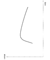
- FIG. 5 is a graph schematically illustrating the relationship between the refrigerant amount and the cooling performance in the cooling device. As shown in FIG. 5, in the cooling device 109 using the phase change of the refrigerant, it is known that there is an optimum amount of the refrigerant, and the cooling performance is deteriorated if the amount of refrigerant is too much or too little.
- Patent Document 1 and Patent Document 2 An example of a technique for adjusting the amount of refrigerant in the cooling device is disclosed in Patent Document 1 and Patent Document 2.
- the refrigerant flowing into each evaporator that cools each electronic device according to the load of each electronic device Adjust the flow rate with a valve.
- Patent Document 3 Another example of a technique for adjusting the amount of refrigerant in the cooling device is disclosed in Patent Document 3.
- the cooling system of Patent Document 3 includes a plurality of heat receiving units (evaporators), a plurality of liquid reservoirs, a liquid tank, and a pump. Each liquid reservoir supplies a refrigerant to each heat receiving portion.
- the liquid tank holds the refrigerant overflowing from each liquid reservoir.
- the pump transports the refrigerant from the liquid tank to each liquid reservoir when the refrigerant is insufficient in each liquid reservoir.
- the cooling system disclosed in Patent Document 3 prevents liquid withering in each heat receiving unit.
- the cooling systems of Patent Document 1 and Patent Document 2 use a valve to adjust the flow rate of the refrigerant flowing into the evaporator. That is, the cooling systems of Patent Document 1 and Patent Document 2 have a problem that the configuration of the cooling system is more complicated than when no valve is used. Moreover, in the cooling system of patent document 1 and patent document 2, energy is required for control of a valve
- the present invention has been made in view of the above problems, and a main object of the present invention is to achieve both improvement of cooling efficiency and a simple device configuration in a cooling device using phase change of refrigerant.
- the cooling device is a sealed container that can hold a refrigerant therein, and has a condensed refrigerant inflow portion that has one end opened on a side surface of the container and allows the condensed refrigerant to flow from the side, and an upper end.
- Refrigerant is supplied from a plurality of gas-liquid separation tanks including a gas refrigerant outflow part that causes the refrigerant in a gaseous state to flow upward, and from the condenser or the gas refrigerant outflow part, the supplied refrigerant is cooled, and the cooled refrigerant is condensed
- refrigerant inlet Comprises a condenser which is supplied with refrigerant from the condenser refrigerant outlet portion, it is absorbed by the supplied coolant, and supplies the heat receiving portion coolant which is endothermic to the gas-liquid mixed refrigerant inlet portion.
- the gas-liquid separation tank is a sealed container capable of holding a refrigerant therein, and has a condensed refrigerant inflow portion for allowing a refrigerant in a condensed state to flow from the side, having one end opened on a side surface of the container.
- a condensing refrigerant outflow part for allowing the refrigerant in a condensed state to flow out downward, the upper end being opened in the lower bottom surface of the container, and a condensing refrigerant bypass part for allowing the refrigerant in a condensed state to flow out and inflow to the side, having one end opened on the side surface.
- the upper end passes through the lower bottom surface, and is installed in a direction parallel to the gas-liquid mixed refrigerant inflow portion for allowing the gas-liquid mixed state refrigerant to flow in from below, and the lower end opens at the upper bottom surface of the container. And a gas refrigerant outflow portion for causing the gaseous refrigerant to flow out upward.
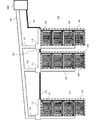
- FIG. 1 is a front view showing an example of the configuration of the cooling device according to the first embodiment of the present invention.
- the cooling device 100 of the present embodiment includes a condenser 200, a plurality of heat receiving units 140, 141, ..., and a plurality of gas-liquid separation tanks 110, 111, ....
- a condenser 200 a plurality of heat receiving units 140, 141, ...
- FIG. 1 three heat receiving units and three gas-liquid separation tanks are illustrated, but the heat receiving units and gas-liquid separation tanks may be an arbitrary number of two or more.
- the condenser 200 releases the heat of the refrigerant to the outside when the heated refrigerant passes through the inside.
- the heat receiving units 140, 141, ... absorb external heat when the cooled refrigerant passes through the inside.
- Each of the heat receiving units 140, 141,... Is supplied with a cooled refrigerant from below and absorbs external heat while moving the supplied refrigerant from below to above to absorb the refrigerant that has absorbed external heat.
- the gas-liquid separation tanks 110, 111, ... are supplied from above.
- the gas-liquid separation tanks 110, 111, ... supply the cooled refrigerant supplied from the condenser 200 to the heat receiving units 140, 141, ..., respectively. Further, the gas-liquid separation tanks 110, 111,... Separate the gas from the heated gas-liquid mixed refrigerant supplied from the heat receiving units 140, 141,. 200.
- the gas-liquid separation tanks 110, 111, ... receive the supply of condensed refrigerant from the condenser 200 via the condensed refrigerant inflow pipes 120, 121, ..., respectively.
- the condensed refrigerant inflow piping 121 is connected in series to the condensed refrigerant inflow piping 120 via the gas-liquid separation tank 110.
- the condensed refrigerant inflow piping 122 is connected in series to the condensed refrigerant inflow piping 121 via the gas-liquid separation tank 111.
- the condensed refrigerant inflow pipes 121, 122,... Are horizontally installed pipes that share the condensed refrigerant between adjacent gas-liquid separation tanks (allowing the condensed refrigerant to flow out and inflow).
- the gas-liquid separation tanks 110, 111, ... supply condensed refrigerant to the heat receiving units 140, 141, ... via the condensed refrigerant outflow pipes 130, 131, ..., respectively.
- the gas-liquid separation tanks 110, 111, ... supply gas-liquid mixed refrigerant from the heat receiving parts 140, 141, ...
- the gas-liquid separation tanks 110, 111, ... supply vaporized refrigerant to the condenser 200 via the gas refrigerant outflow pipe 160 and the gas refrigerant outflow pipes 161, 162, ..., respectively.
- the condensed refrigerant inflow pipes 120, 121,... are connected to positions lower than the refrigerant liquid level (not shown) in the gas-liquid separation tanks 110, 111,.
- FIG. 2 is a cross-sectional view showing an example of the configuration of the gas-liquid separation tank according to the first embodiment of the present invention.
- the gas-liquid separation tank 110 is demonstrated, the gas-liquid separation tank 111, ... has the same structure as the gas-liquid separation tank 110.
- the gas-liquid separation tank 110 is a sealed container capable of holding a refrigerant inside.
- the gas-liquid separation tank 110 is connected to the condensed refrigerant inflow pipe 120 at the condensed refrigerant inflow portion 190 on the side surface. However, in the most upstream gas-liquid separation tank 110 (closest to the condenser 200), the condensed refrigerant inflow portion 190 may be on the upper bottom surface.
- the gas-liquid separation tank 110 is connected to the condensed refrigerant outflow pipe 130 at the condensed refrigerant outflow portion 210 on the lower bottom surface of the gas-liquid separation tank 110. Condensed refrigerant outflow pipe 130 is connected to the bottom of heat receiving unit 140.
- the gas-liquid separation tank 110 is connected to the condensed refrigerant inflow pipe 121 in the condensed refrigerant bypass section 230 on the side surface (allows the condensed refrigerant to flow out and inflow).
- the condensed refrigerant bypass unit 230 may not exist.
- the gas-liquid separation tank 110 shares the condensed refrigerant 7 with the gas-liquid separation tank downstream through the condensed refrigerant bypass unit 230.
- the opening of the condensed refrigerant inflow portion 190 and the opening of the condensed refrigerant bypass portion 230 are provided at a position lower than the liquid level of the condensed refrigerant 7.
- the condensed refrigerant inflow section 190 allows the condensed refrigerant 7 to flow into the gas-liquid separation tank 110 from the side or from above, or allows the condensed refrigerant 7 to flow into and out of the side.
- the condensed refrigerant bypass unit 230 causes the condensed refrigerant 7 to flow out and inflow to the side.
- the condensed refrigerant outflow portion 210 opens at the lower bottom surface of the gas-liquid separation tank 110 and causes the condensed refrigerant 7 to flow out downward.
- the heat receiving unit 140 is connected to the gas-liquid mixed refrigerant inflow pipe 150 at the top.
- the gas-liquid mixed refrigerant inflow pipe 150 is connected to a gas-liquid mixed refrigerant inflow part 170 on the lower bottom surface of the gas-liquid separation tank 110.
- the gas-liquid mixed refrigerant inflow portion 170 passes through the lower bottom surface of the gas-liquid separation tank 110 and has an upper end inside the gas-liquid separation tank 110.
- the gas-liquid mixed refrigerant inflow portion 170 is expanded so that, for example, the inside diameter of the gas-liquid separation tank 110 increases as the inner diameter of the upper end increases. That is, the gas-liquid mixed refrigerant inflow portion 170 allows the gas-liquid mixed two-phase flow 8 to flow from below, and jets the gas refrigerant 10 of the gas-liquid mixed two-phase flow 8 that has flowed upward. Then, the gas-liquid mixed refrigerant inflow portion 170 ejects the liquid refrigerant 9 of the gas-liquid mixed two-phase flow 8 that has flowed in toward the wall surface of the gas-liquid separation tank 110.
- the gas-liquid separation tank 110 has, for example, a gas refrigerant outflow portion 180 coaxially with the gas / liquid mixed refrigerant inflow portion 170.
- a gas refrigerant outflow pipe 160 is connected to the gas refrigerant outflow portion 180.
- the gas refrigerant outflow portion 180 opens at the upper bottom surface of the gas-liquid separation tank 110 and causes the gas refrigerant 10 to flow out upward.
- the bottom of the gas-liquid separation tank 110 is filled with the condensed refrigerant 7. Further, the upper end of the gas-liquid mixed refrigerant inflow portion 170 is installed at a position higher than the liquid level of the condensed refrigerant 7.
- the heat receiving units 140, 141,... Receive the heat of the device to be cooled (not shown), the condensed refrigerant 7 boils inside the heat receiving units 140, 141,. . And in the heat receiving part 140,141, ..., a vapor
- the gas-liquid mixed two-phase flow 8 is a mixture of the liquid refrigerant 9 and the gas refrigerant 10.
- the gas-liquid mixed two-phase flow 8 flows into the gas-liquid separation tanks 110, 111, ... via the gas-liquid mixed refrigerant inflow pipes 150, 151, ...
- the liquid refrigerant 9 in the gas-liquid mixed two-phase flow 8 rises along the inner wall of the gas-liquid mixed refrigerant inflow portion 170. Then, the liquid refrigerant 9 is ejected from the upper end of the gas-liquid mixed refrigerant inflow portion 170 toward the upper side of the gas-liquid mixed refrigerant inflow portion 170. Then, the liquid refrigerant 9 collides with the upper bottom surface or the side surface in the gas-liquid separation tanks 110, 111,..., And then falls into the gas-liquid separation tanks 110, 111,. The liquid refrigerant 9 dropped into the gas-liquid separation tanks 110, 111,... Is mixed with the condensed refrigerant 7, and supplied to the heat receiving units 140, 141,.
- the gas refrigerant 10 in the gas-liquid mixed two-phase flow 8 continues to rise straight after being ejected from the upper end of the gas-liquid mixed refrigerant inflow portion 170. Then, after the gas refrigerant 10 is condensed by the condenser 200, it is returned to the gas-liquid separation tanks 110, 111,... Via the condensed refrigerant inflow pipe 120.
- the gas refrigerant 10 in the gas-liquid mixed two-phase flow 8 passes through the gas refrigerant outflow pipes 161, 162,. Flow into.
- the liquid refrigerant 9 is mixed with the condensed refrigerant flowing in from the condensed refrigerant inflow pipes 120, 121,... In the gas-liquid separation tanks 110, 111,. It flows out from inflow piping 121,122, ....
- the gas refrigerant 10 is condensed (liquefied) by the condenser 200 and then refluxed to the gas-liquid separation tanks 110, 111,... Via the condensed refrigerant inflow pipe 120.
- the gas-liquid separation tanks 110, 111,... are connected in series by the condensed refrigerant inflow pipes 120, 121,. That is, the condensed refrigerant 7 is shared between the gas-liquid separation tanks 110, 111,. As a result, the amount of the condensed refrigerant 7 flowing into the heat receiving portions 140, 141,.
- no valve or pump is required to adjust the amount of refrigerant flowing into each heat receiving part. Therefore, when the phase change cooling gas-liquid separation tank is introduced in the cooling device using the phase change of the refrigerant, the cooling device 100 of the present embodiment can achieve both improved cooling efficiency and a simple device configuration. There is an effect. (Second Embodiment) Next, a second embodiment of the present invention based on the first embodiment of the present invention will be described.
- the cooling device in the present embodiment includes a plurality of heat receiving units per gas-liquid separation tank.
- FIG. 3 is a front view showing an example of the configuration of the cooling device according to the second embodiment of the present invention.
- the cooling device includes three gas-liquid separation tanks, and there are four heat receiving portions per one gas-liquid separation tank.
- the number of cooling devices and heat receiving units in the present embodiment may be an arbitrary number of two or more.
- the cooling device 105 of the present embodiment includes a condenser 200, collective heat receiving units 145, 146,... Including a plurality of heat receiving units, and gas-liquid separation tanks 110, 111,.
- the cooling device 105 includes condensed refrigerant outflow pipes 135, 136,... Branched at the lower end side instead of the condensed refrigerant outflow pipes 130, 131,.
- Each branch of the condensed refrigerant outflow pipes 135, 136,... Is connected to each heat receiving part included in the plurality of collective heat receiving parts 145, 146,.
- the cooling device 105 includes gas-liquid mixed refrigerant inflow pipes 155, 156,... Branched at the lower end side instead of the gas-liquid mixed refrigerant inflow pipes 150, 151,.
- Each branch of the gas-liquid mixed refrigerant inflow pipes 155, 156,... Is connected to each heat receiving part included in the plurality of collective heat receiving parts 145, 146,.
- the operation in the present embodiment is the same as the operation in the first embodiment except that the heat receiving units included in the plurality of collective heat receiving units 145, 146,... Operate in parallel.
- the cooling device 105 of the present embodiment is the same as that of the first embodiment except that the heat receiving units included in the plurality of collective heat receiving units 145, 146,. It operates similarly to the cooling device 100. Therefore, the cooling device 105 according to the present embodiment has the same effect as the cooling device 100 according to the first embodiment.
- coolant inflow piping 121,122, ... is not horizontal and has a drooping shape, it does not affect the cooling performance.
- the present invention can be used in applications for cooling an arbitrary heat source such as a semiconductor device, an electronic device, or a server.
Landscapes
- Engineering & Computer Science (AREA)
- Physics & Mathematics (AREA)
- General Engineering & Computer Science (AREA)
- Theoretical Computer Science (AREA)
- Thermal Sciences (AREA)
- Human Computer Interaction (AREA)
- General Physics & Mathematics (AREA)
- Life Sciences & Earth Sciences (AREA)
- Sustainable Development (AREA)
- Mechanical Engineering (AREA)
- Microelectronics & Electronic Packaging (AREA)
- Cooling Or The Like Of Electrical Apparatus (AREA)
Abstract
(課題)冷媒の相変化を利用した冷却装置において、気液分離タンクを導入した場合に、冷却効率の向上と、単純な装置構成とを両立させる。 (解決手段)内部に冷媒を保持可能な密閉容器であって、一端が容器の側面に開口した、側方から凝縮状態の冷媒を流入させる凝縮冷媒流入部と、上端が容器の下底面において開口した、下方へ凝縮状態の冷媒を流出させる凝縮冷媒流出部と、一端が側面に開口した、側方へ凝縮状態の冷媒を流出及び流入させる凝縮冷媒バイパス部と、上端が下底面を貫通し、下方から気液混合状態の冷媒を流入させる気液混合冷媒流入部と、気液混合冷媒流入部と平行な向きに設置され、下端が容器の上底面において開口した、上方へ気体状態の冷媒を流出させる気体冷媒流出部とを備える。
Description
本発明は、冷媒の相変化を利用した冷却技術に関する。
サーバの大規模化や高集積化等に伴い、サーバの発熱量が増大してきた。そのため、データセンター等において、サーバ等の機器の冷却の効率化が求められている。サーバ等の機器の冷却では、相変化冷却(蒸発冷却、沸騰冷却)方式が用いられることが多い。相変化冷却方式では、冷却装置の内部に封入された熱媒体(冷媒)の相変化を利用して機器が冷却される。
図4は、本発明における課題を説明する図である。より具体的には、図4は、冷媒の相変化を利用した冷却装置109の構成を示す正面図である。
冷却装置109は、凝縮器200と、受熱部140、141、142とを含む。
凝縮器200は、加熱された冷媒が内部を通過する際に、冷媒が有する熱を外部へ放出することにより、冷媒を冷却する。凝縮器200が熱を放出すると、凝縮器200中の冷媒は凝縮(液化)する。
受熱部140、141、142は、凝縮器200により冷却された冷媒が内部を通過する際に、外部の熱を吸収することにより、冷媒を加熱する。受熱部140、141、142が外部の熱を吸収すると、受熱部140、141、142中の冷媒は沸騰(気化)する。
受熱部140、141、142はそれぞれ、凝縮冷媒流入配管120及び凝縮冷媒流入配管121、122、123と、気液混合冷媒流出配管150及び気液混合冷媒流出配管151、152、153とを経由して、凝縮器200に並列に接続される。ここで、凝縮冷媒流入配管121、122、123は、凝縮冷媒流入配管120の各受熱部側が分岐した配管である。凝縮冷媒流入配管120及び凝縮冷媒流入配管121、122、123は、凝縮器200により冷却された冷媒を受熱部140、141、142へ輸送する。又、気液混合冷媒流出配管151、152、153は、気液混合冷媒流出配管150の各受熱器側が分岐した配管である。気液混合冷媒流出配管150及び気液混合冷媒流出配管151、152、153は、受熱部140、141、142により加熱された冷媒を凝縮器200へ輸送する。冷媒は、受熱部140、141、142と凝縮器200との間で、自然循環させられる。
受熱部140、141、142が凝縮器200に並列に接続された構成において、冷媒を自然循環させるためには、気液混合冷媒流出配管150と凝縮冷媒流入配管120とは、水平面に対して勾配を成す必要がある。
ところが、気液混合冷媒流出配管150と凝縮冷媒流入配管120とが水平面に対して勾配を成すと、凝縮器200により凝縮された冷媒は、凝縮器200に最も近い受熱部140へ最も多く流入し、凝縮器200から最も遠い受熱部142へ最も少なく流入するという現象が発生する。
図5は、冷却装置における、冷媒量と冷却性能との関係を模式的に説明するグラフである。図5に示すように、冷媒の相変化を利用した冷却装置109では、最適な冷媒量が存在し、冷媒が多過ぎても少な過ぎても冷却性能が低下することが知られている。
冷却装置における冷媒量を調整する技術の一例が、特許文献1及び特許文献2に開示されている。特許文献1及び特許文献2の冷却システムは、冷媒を循環させて複数の電子機器を冷却する際に、各電子機器の負荷に応じて、各電子機器を冷却する各蒸発器に流入させる冷媒の流量をバルブによって調整する。
冷却装置における冷媒量を調整する技術の別の一例が、特許文献3に開示されている。特許文献3の冷却システムは、複数の受熱部(蒸発器)と、複数の液溜めと、液タンクと、ポンプとを含む。各液溜めは、各受熱部へ冷媒を供給する。液タンクは、各液溜めから溢れた冷媒を保持する。ポンプは、各液溜めにおいて冷媒が不足した際に液タンクから各液溜めへ冷媒を輸送する。上記構成の結果、特許文献3の冷却システムは、各受熱部における液枯れを防止する。
特許文献1及び特許文献2の冷却システムは、蒸発器へ流入させる冷媒の流量の調整にバルブを使用する。つまり、特許文献1及び特許文献2の冷却システムには、バルブを使用しない場合に比べて、冷却システムの構成が複雑であるという問題がある。又、特許文献1及び特許文献2の冷却システムでは、バルブの制御にエネルギーを要する。
特許文献3の冷却システムでは、ポンプを動作させるために、電源や、ポンプ制御部等が必要である。つまり、特許文献3の冷却システムには、ポンプがない場合に比べて、冷却システムの構成が複雑であるという問題がある。又、特許文献3の冷却システムでは、ポンプの制御にエネルギーを要する。
本発明は、上記課題に鑑みてなされたもので、冷媒の相変化を利用した冷却装置において、冷却効率の向上と、単純な装置構成とを両立することを主たる目的とする。
本発明の一態様において、冷却装置は、内部に冷媒を保持可能な密閉容器であって、一端が容器の側面に開口した、側方から凝縮状態の冷媒を流入させる凝縮冷媒流入部と、上端が容器の下底面において開口した、下方へ凝縮状態の冷媒を流出させる凝縮冷媒流出部と、一端が側面に開口した、側方へ凝縮状態の冷媒を流出及び流入させる凝縮冷媒バイパス部と、上端が下底面を貫通し、下方から気液混合状態の冷媒を流入させる気液混合冷媒流入部と、気液混合冷媒流入部と平行な向きに設置され、下端が容器の上底面において開口した、上方へ気体状態の冷媒を流出させる気体冷媒流出部とを含む複数の気液分離タンクと、凝縮器又は気体冷媒流出部から冷媒を供給され、供給された冷媒を冷却し、冷却した冷媒を凝縮冷媒流入部へ供給する凝縮器と、凝縮冷媒流出部から冷媒を供給され、供給された冷媒に吸熱させ、吸熱させた冷媒を気液混合冷媒流入部へ供給する受熱部とを備える。
本発明の一態様において、気液分離タンクは、内部に冷媒を保持可能な密閉容器であって、一端が容器の側面に開口した、側方から凝縮状態の冷媒を流入させる凝縮冷媒流入部と、上端が容器の下底面において開口した、下方へ凝縮状態の冷媒を流出させる凝縮冷媒流出部と、一端が側面に開口した、側方へ凝縮状態の冷媒を流出及び流入させる凝縮冷媒バイパス部と、上端が下底面を貫通し、下方から気液混合状態の冷媒を流入させる気液混合冷媒流入部と、気液混合冷媒流入部と平行な向きに設置され、下端が容器の上底面において開口した、上方へ気体状態の冷媒を流出させる気体冷媒流出部とを備える。
本発明によれば、冷媒の相変化を利用した冷却装置において、気液分離タンクを導入した場合に、冷却効率の向上と、単純な装置構成とを両立できるという効果がある。
以下、本発明の実施形態について、図面を参照して詳細に説明する。なお、すべての図面において、同等な構成要素には同じ符号を付し、適宜説明を省略する。
(第1の実施形態)
本実施形態における構成について説明する。
(第1の実施形態)
本実施形態における構成について説明する。
図1は、本発明の第1の実施形態における冷却装置の構成の一例を示す正面図である。
本実施形態の冷却装置100は、凝縮器200と、複数の受熱部140、141、・・・と、複数の気液分離タンク110、111、・・・とを含む。尚、図1では、3台の受熱部及び3台の気液分離タンクを例示しているが、受熱部及び気液分離タンクは2台以上の任意の台数であってよい。
凝縮器200は、加熱された冷媒が内部を通過する際に、冷媒が有する熱を外部へ放出する。
受熱部140、141、・・・は、冷却された冷媒が内部を通過する際に、外部の熱を吸収する。受熱部140、141、・・・はそれぞれ、冷却された冷媒を下方から供給され、外部の熱を吸収させながら、供給された冷媒を下方から上方へ移動させ、外部の熱を吸収した冷媒を上方から気液分離タンク110、111、・・・へ供給する。
気液分離タンク110、111、・・・はそれぞれ、凝縮器200から供給された冷却された冷媒を受熱部140、141、・・・へ供給する。又、気液分離タンク110、111、・・・はそれぞれ、受熱部140、141、・・・から供給された加熱された気液混合状態の冷媒から気体を分離し、分離した気体を凝縮器200へ供給する。気液分離タンク110、111、・・・はそれぞれ、凝縮冷媒流入配管120、121、・・・を経由して、凝縮器200から、凝縮した冷媒の供給を受ける。ここで、凝縮冷媒流入配管121は、気液分離タンク110を経由して、凝縮冷媒流入配管120に直列に接続される。又、凝縮冷媒流入配管122は、気液分離タンク111を経由して、凝縮冷媒流入配管121に直列に接続される。凝縮冷媒流入配管121、122、・・・は、隣接する気液分離タンク間で凝縮冷媒を共有する(凝縮冷媒の流出及び流入を可能にする)、水平に設置された配管である。気液分離タンク110、111、・・・はそれぞれ、凝縮冷媒流出配管130、131、・・・を経由して、受熱部140、141、・・・へ、凝縮した冷媒を供給する。気液分離タンク110、111、・・・はそれぞれ、気液混合冷媒流入配管150、151、・・・を経由して、受熱部140、141、・・・から、気液混合した冷媒の供給を受ける。気液分離タンク110、111、・・・はそれぞれ、気体冷媒流出配管160及び気体冷媒流出配管161、162、・・・を経由して、凝縮器200へ、気化した冷媒を供給する。
凝縮冷媒流入配管120、121、・・・は、気液分離タンク110、111、・・・内の冷媒液面(不図示)よりも低い位置に接続される。
図2は、本発明の第1の実施形態における気液分離タンクの構成の一例を示す断面図である。ここでは、気液分離タンク110について説明するが、気液分離タンク111、・・・は、気液分離タンク110と同じ構成を有する。
気液分離タンク110は、内部に冷媒を保持可能な密閉容器である。気液分離タンク110は、側面にある凝縮冷媒流入部190において、凝縮冷媒流入配管120に接続される。但し、最上流の(凝縮器200に最も近い)気液分離タンク110では、凝縮冷媒流入部190は上底面にあってもよい。又、気液分離タンク110は、気液分離タンク110の下底面にある凝縮冷媒流出部210において、凝縮冷媒流出配管130に接続される。又、凝縮冷媒流出配管130は、受熱部140の底部に接続される。気液分離タンク110は、側面にある凝縮冷媒バイパス部230において、凝縮冷媒流入配管121に接続される(凝縮冷媒の流出及び流入を可能にする)。但し、最下流の(凝縮器200から最も遠い)気液分離タンク112では、凝縮冷媒バイパス部230は存在しなくてもよい。つまり、気液分離タンク110は、凝縮冷媒バイパス部230を経由して、より下流の気液分離タンクと凝縮冷媒7を共有する。
凝縮冷媒流入部190の開口部及び凝縮冷媒バイパス部230の開口部は、凝縮冷媒7の液面よりも低い位置に設けられる。凝縮冷媒流入部190は、側方又は上方から気液分離タンク110へ凝縮冷媒7を流入させるか、又は側方へ凝縮冷媒7を流入及び流出させる。凝縮冷媒バイパス部230は、側方へ凝縮冷媒7を流出及び流入させる。
凝縮冷媒流出部210は、気液分離タンク110の下底面に開口し、下方へ凝縮冷媒7を流出させる。
受熱部140は、上部に気液混合冷媒流入配管150が接続される。又、気液混合冷媒流入配管150は、気液分離タンク110の下底面にある気液混合冷媒流入部170に接続される。
気液混合冷媒流入部170は、気液分離タンク110の下底面を貫通して、気液分離タンク110の内部に上端を有する。気液混合冷媒流入部170は、例えば、気液分離タンク110の内部において、上端の内径が上に行くに従い広がるよう拡管されている。つまり、気液混合冷媒流入部170は、下方から気液混合二相流8を流入させ、流入させた気液混合二相流8のうちの気体冷媒10を上方へ噴出させる。そして、気液混合冷媒流入部170は、流入させた気液混合二相流8のうちの液体冷媒9を気液分離タンク110の壁面へ向けて噴出させる。
気液分離タンク110は、例えば、気液混合冷媒流入部170と同軸上に、気体冷媒流出部180を有する。気体冷媒流出部180には、気体冷媒流出配管160が接続されている。気体冷媒流出部180は、気液分離タンク110の上底面に開口し、上方へ気体冷媒10を流出させる。
気液分離タンク110の底部には、凝縮冷媒7が充填されている。又、気液混合冷媒流入部170の上端は、凝縮冷媒7の液面よりも高い位置になるよう設置される。
本実施形態における動作について説明する。
受熱部140、141、・・・が冷却対象機器(不図示)の熱を受熱すると、受熱部140、141、・・・の内部において、凝縮冷媒7が沸騰し、その結果、蒸気が発生する。そして、受熱部140、141、・・・の内部において、蒸気は気液混合二相流8となり、受熱部140、141、・・・の上部へ移動する。ここで、気液混合二相流8とは、液体冷媒9と気体冷媒10との混合物であることとする。
気液混合二相流8は、気液混合冷媒流入配管150、151、・・・を経由して、気液分離タンク110、111、・・・へ流入する。
この際、気液混合二相流8中の液体冷媒9は、気液混合冷媒流入部170の内壁に沿って上昇する。そして、液体冷媒9は、気液混合冷媒流入部170の上端から気液混合冷媒流入部170の上方に向かって噴出する。そして、液体冷媒9は、気液分離タンク110、111、・・・内の上底面又は側面に衝突した後、重力により気液分離タンク110、111、・・・内に落下する。気液分離タンク110、111、・・・内に落下した液体冷媒9は、凝縮冷媒7と混合し、凝縮冷媒流出配管130を経由して受熱部140、141、・・・へ供給される。
一方、気液混合二相流8中の気体冷媒10は、気液混合冷媒流入部170の上端から噴出した後も真直ぐ上昇を続ける。そして、気体冷媒10は、凝縮器200により凝縮された後、凝縮冷媒流入配管120を経由して気液分離タンク110、111、・・・へ還流される。
気液分離タンク110、111、・・・内ではそれぞれ、気液混合二相流8中の気体冷媒10は、気体冷媒流出配管161、162、・・・を経由して、気体冷媒流出配管160へ流入する。
一方、液体冷媒9は、気液分離タンク110、111、・・・内において、凝縮冷媒流入配管120、121、・・・から流入した凝縮冷媒と混合して、凝縮冷媒流出配管130又は凝縮冷媒流入配管121、122、・・・から流出する。
気体冷媒流出配管161、162、・・・から気体冷媒流出配管160へ流入した気体冷媒10は、凝縮器200へ流入する。そして、気体冷媒10は、凝縮器200により凝縮(液化)された後、凝縮冷媒流入配管120を経由して気液分離タンク110、111、・・・へ還流される。
以上説明したように、本実施形態の冷却装置100では、各気液分離タンク110、111、・・・は、凝縮冷媒流入配管120、121、・・・により直列に接続される。つまり、気液分離タンク110、111、・・・間において、凝縮冷媒7が共有される。その結果、各受熱部140、141、・・・に流入する凝縮冷媒7の量が均一化される。又、本実施形態の冷却装置100では、各受熱部に流入する冷媒量の調節のためにバルブやポンプを必要としない。従って、本実施形態の冷却装置100には、冷媒の相変化を利用した冷却装置において、相変化冷却気液分離タンクを導入した場合に、冷却効率の向上と、単純な装置構成とを両立できるという効果がある。
(第2の実施形態)
次に、本発明の第1の実施形態を基本とする、本発明の第2の実施形態について説明する。本実施形態における冷却装置は、1台の気液分離タンクあたり、複数の受熱部を備える。
(第2の実施形態)
次に、本発明の第1の実施形態を基本とする、本発明の第2の実施形態について説明する。本実施形態における冷却装置は、1台の気液分離タンクあたり、複数の受熱部を備える。
本実施形態における構成について説明する。
図3は、本発明の第2の実施形態における冷却装置の構成の一例を示す正面図である。図3では、冷却装置は3台の気液分離タンクを含み、1台の気液分離タンクあたり、受熱部が4つの場合を示している。しかしながら、本実施形態における冷却装置及び受熱部の台数は、2台以上の任意の台数であってよい。
本実施形態の冷却装置105は、凝縮器200と、複数台の受熱部を含む集合受熱部145、146、・・・と、気液分離タンク110、111、・・・とを含む。
冷却装置105は、第1の実施形態の凝縮冷媒流出配管130、131、・・・の代わりに、下端側が分岐した凝縮冷媒流出配管135、136、・・・を含む。凝縮冷媒流出配管135、136、・・・の各分岐は、複数台の集合受熱部145、146、・・・に含まれる各受熱部に接続される。
又、冷却装置105は、第1の実施形態の気液混合冷媒流入配管150、151、・・・の代わりに、下端側が分岐した気液混合冷媒流入配管155、156、・・・を含む。気液混合冷媒流入配管155、156、・・・の各分岐は、複数台の集合受熱部145、146、・・・に含まれる各受熱部に接続される。
本実施形態におけるその他の構成は、第1の実施形態における構成と同じである。
本実施形態における動作について説明する。
本実施形態における動作は、複数台の集合受熱部145、146、・・・に含まれる各受熱部が並行して動作することを除き、第1の実施形態における動作と同じである。
以上説明したように、本実施形態の冷却装置105は、複数台の集合受熱部145、146、・・・に含まれる各受熱部が並行して動作することを除き、第1の実施形態の冷却装置100と同様に動作する。従って、本実施形態における冷却装置105には、第1の実施形態の冷却装置100と同様な効果がある。
尚、凝縮冷媒流入配管121、122、・・・は、水平でなく、垂れ下がった形状であっても冷却性能に影響はない。
以上、本発明を、上述した各実施形態及びその変形例によって例示的に説明した。しかしながら、本発明の技術的範囲は、上述した各実施形態及びその変形例に記載した範囲に限定されない。当業者には、係る実施形態に対して多様な変更又は改良を加えることが可能であることは明らかである。そのような場合、係る変更又は改良を加えた新たな実施形態も、本発明の技術的範囲に含まれ得る。そしてこのことは、請求の範囲に記載した事項により明らかである。
この出願は、2017年3月8日に出願された日本出願特願2017-043527を基礎とする優先権を主張し、その開示の全てをここに取り込む。
本発明は、半導体装置、電子機器、サーバ等の任意の熱源を冷却する用途において利用できる。
7 凝縮冷媒
8 気液混合二相流
9 液体冷媒
10 気体冷媒
100、105、109 冷却装置
110、111、112 気液分離タンク
120、121、122 凝縮冷媒流入配管
130、131、132、135、136、137 凝縮冷媒流出配管
140、141、142 受熱部
145、146、147 集合受熱部
150、151、152、155、156、157 気液混合冷媒流入配管
160 気体冷媒流出配管
161、162、163 気体冷媒流出配管
170 気液混合冷媒流入部
180 気体冷媒流出部
190 凝縮冷媒流入部
210 凝縮冷媒流出部
230 凝縮冷媒バイパス部
200 凝縮器
8 気液混合二相流
9 液体冷媒
10 気体冷媒
100、105、109 冷却装置
110、111、112 気液分離タンク
120、121、122 凝縮冷媒流入配管
130、131、132、135、136、137 凝縮冷媒流出配管
140、141、142 受熱部
145、146、147 集合受熱部
150、151、152、155、156、157 気液混合冷媒流入配管
160 気体冷媒流出配管
161、162、163 気体冷媒流出配管
170 気液混合冷媒流入部
180 気体冷媒流出部
190 凝縮冷媒流入部
210 凝縮冷媒流出部
230 凝縮冷媒バイパス部
200 凝縮器
Claims (4)
- 内部に冷媒を保持可能な密閉容器であって、
一端が前記容器の側面に開口した、側方から凝縮状態の前記冷媒を流入させる凝縮冷媒流入部と、
上端が前記容器の下底面において開口した、下方へ凝縮状態の前記冷媒を流出させる凝縮冷媒流出部と、
一端が前記側面に開口した、側方へ凝縮状態の前記冷媒を流出及び流入させる凝縮冷媒バイパス部と、
上端が前記下底面を貫通し、下方から気液混合状態の前記冷媒を流入させる気液混合冷媒流入部と、
前記気液混合冷媒流入部と平行な向きに設置され、下端が前記容器の上底面において開口した、上方へ気体状態の前記冷媒を流出させる気体冷媒流出部と
を含む複数の気液分離タンクと、
前記気体冷媒流出部から前記冷媒を供給され、
供給された前記冷媒を冷却し、
冷却した前記冷媒を前記凝縮冷媒流入部へ供給する
凝縮器と、
前記凝縮器又は前記凝縮冷媒流出部から前記冷媒を供給され、
供給された前記冷媒に吸熱させ、
吸熱させた前記冷媒を前記気液混合冷媒流入部へ供給する
受熱部と
を備えた冷却装置。 - ある前記気液分離タンクの前記凝縮冷媒バイパス部と、別の前記気液分離タンクの前記凝縮冷媒流入部とは、水平に設置された配管により接続された
請求項1に記載の冷却装置。 - 前記気液分離タンクは、複数の前記受熱部のそれぞれに並列に接続された
請求項1又は2に記載の冷却装置。 - 内部に冷媒を保持可能な密閉容器であって、
一端が前記容器の側面に開口した、側方から凝縮状態の前記冷媒を流入させる凝縮冷媒流入部と、
上端が前記容器の下底面において開口した、下方へ凝縮状態の前記冷媒を流出させる凝縮冷媒流出部と、
一端が前記側面に開口した、側方へ凝縮状態の前記冷媒を流出及び流入させる凝縮冷媒バイパス部と、
上端が前記下底面を貫通し、下方から気液混合状態の前記冷媒を流入させる気液混合冷媒流入部と、
前記気液混合冷媒流入部と平行な向きに設置され、下端が前記容器の上底面において開口した、上方へ気体状態の前記冷媒を流出させる気体冷媒流出部と
を備えた気液分離タンク。
Applications Claiming Priority (2)
| Application Number | Priority Date | Filing Date | Title |
|---|---|---|---|
| JP2017043527 | 2017-03-08 | ||
| JP2017-043527 | 2017-03-08 |
Publications (1)
| Publication Number | Publication Date |
|---|---|
| WO2018164085A1 true WO2018164085A1 (ja) | 2018-09-13 |
Family
ID=63448144
Family Applications (1)
| Application Number | Title | Priority Date | Filing Date |
|---|---|---|---|
| PCT/JP2018/008448 WO2018164085A1 (ja) | 2017-03-08 | 2018-03-06 | 冷却装置及び気液分離タンク |
Country Status (1)
| Country | Link |
|---|---|
| WO (1) | WO2018164085A1 (ja) |
Citations (7)
| Publication number | Priority date | Publication date | Assignee | Title |
|---|---|---|---|---|
| JPS5223751U (ja) * | 1975-08-09 | 1977-02-19 | ||
| JPS563372U (ja) * | 1979-06-21 | 1981-01-13 | ||
| JPH0355443A (ja) * | 1989-07-25 | 1991-03-11 | Matsushita Electric Ind Co Ltd | 暖房機 |
| JPH0359322A (ja) * | 1989-07-26 | 1991-03-14 | Matsushita Electric Ind Co Ltd | 暖房機 |
| JPH0658653A (ja) * | 1992-08-04 | 1994-03-04 | Daikin Ind Ltd | 気液分離器 |
| CN101814469A (zh) * | 2009-02-20 | 2010-08-25 | 王玉富 | 重力循环蒸发冷却半导体功率器件封装 |
| WO2016047098A1 (ja) * | 2014-09-26 | 2016-03-31 | 日本電気株式会社 | 冷媒中継装置、それを用いた冷却装置、および冷却方法 |
-
2018
- 2018-03-06 WO PCT/JP2018/008448 patent/WO2018164085A1/ja active Application Filing
Patent Citations (7)
| Publication number | Priority date | Publication date | Assignee | Title |
|---|---|---|---|---|
| JPS5223751U (ja) * | 1975-08-09 | 1977-02-19 | ||
| JPS563372U (ja) * | 1979-06-21 | 1981-01-13 | ||
| JPH0355443A (ja) * | 1989-07-25 | 1991-03-11 | Matsushita Electric Ind Co Ltd | 暖房機 |
| JPH0359322A (ja) * | 1989-07-26 | 1991-03-14 | Matsushita Electric Ind Co Ltd | 暖房機 |
| JPH0658653A (ja) * | 1992-08-04 | 1994-03-04 | Daikin Ind Ltd | 気液分離器 |
| CN101814469A (zh) * | 2009-02-20 | 2010-08-25 | 王玉富 | 重力循环蒸发冷却半导体功率器件封装 |
| WO2016047098A1 (ja) * | 2014-09-26 | 2016-03-31 | 日本電気株式会社 | 冷媒中継装置、それを用いた冷却装置、および冷却方法 |
Similar Documents
| Publication | Publication Date | Title |
|---|---|---|
| CN104115579B (zh) | 冷却设备和冷却系统 | |
| US10845127B2 (en) | Cooling device | |
| US20170303432A1 (en) | Refrigerant intermediary device, cooling device including the same, and cooling method | |
| US20070209782A1 (en) | System and method for cooling a server-based data center with sub-ambient cooling | |
| CN104040278A (zh) | 冷却装置和使用该冷却装置的电子装置 | |
| JP6773558B2 (ja) | 相変化冷却装置および相変化冷却方法 | |
| WO2016159056A1 (ja) | 熱媒体分配装置および熱媒体分配方法 | |
| WO2017110740A1 (ja) | 放熱装置、それを用いた相変化冷却装置、および放熱方法 | |
| JP6280170B2 (ja) | 濃縮装置 | |
| JP6419629B2 (ja) | 冷熱回収用ガス気化器 | |
| US20180023899A1 (en) | Heat exchanger comprising a liquid-refrigerant distribution device | |
| WO2018164085A1 (ja) | 冷却装置及び気液分離タンク | |
| WO2018164084A1 (ja) | 冷却装置及び気液分離タンク | |
| JP5869646B1 (ja) | 冷媒供給装置および冷却装置および冷却システム | |
| JP6904704B2 (ja) | 相変化冷却装置および相変化冷却方法 | |
| JP6597074B2 (ja) | 冷却システム | |
| JP6424936B1 (ja) | 気液分離装置、リアドア、冷却装置、及び気液分離方法 | |
| JP2017041577A (ja) | 冷却装置および冷却方法 | |
| JP2015025610A (ja) | 三段昇温型吸収ヒートポンプ | |
| JP6521793B2 (ja) | 吸収ヒートポンプ | |
| JP6801665B2 (ja) | 相変化冷却装置およびその制御方法 | |
| JP6390702B2 (ja) | 発熱体の冷却システム、及びリザーブタンク | |
| WO2023042896A1 (ja) | 吸収器ユニット、熱交換ユニット、及び吸収式冷凍機 | |
| JP2015064141A (ja) | 冷却装置 | |
| JP2010223463A (ja) | 沸騰冷却装置 |
Legal Events
| Date | Code | Title | Description |
|---|---|---|---|
| 121 | Ep: the epo has been informed by wipo that ep was designated in this application |
Ref document number: 18763931 Country of ref document: EP Kind code of ref document: A1 |
|
| NENP | Non-entry into the national phase |
Ref country code: DE |
|
| 122 | Ep: pct application non-entry in european phase |
Ref document number: 18763931 Country of ref document: EP Kind code of ref document: A1 |