WO2018163789A1 - シフトレンジ制御装置 - Google Patents
シフトレンジ制御装置 Download PDFInfo
- Publication number
- WO2018163789A1 WO2018163789A1 PCT/JP2018/005826 JP2018005826W WO2018163789A1 WO 2018163789 A1 WO2018163789 A1 WO 2018163789A1 JP 2018005826 W JP2018005826 W JP 2018005826W WO 2018163789 A1 WO2018163789 A1 WO 2018163789A1
- Authority
- WO
- WIPO (PCT)
- Prior art keywords
- duty
- motor
- control
- abnormal
- energization
- Prior art date
- Legal status (The legal status is an assumption and is not a legal conclusion. Google has not performed a legal analysis and makes no representation as to the accuracy of the status listed.)
- Ceased
Links
Images


Classifications
-
- B—PERFORMING OPERATIONS; TRANSPORTING
- B60—VEHICLES IN GENERAL
- B60L—PROPULSION OF ELECTRICALLY-PROPELLED VEHICLES; SUPPLYING ELECTRIC POWER FOR AUXILIARY EQUIPMENT OF ELECTRICALLY-PROPELLED VEHICLES; ELECTRODYNAMIC BRAKE SYSTEMS FOR VEHICLES IN GENERAL; MAGNETIC SUSPENSION OR LEVITATION FOR VEHICLES; MONITORING OPERATING VARIABLES OF ELECTRICALLY-PROPELLED VEHICLES; ELECTRIC SAFETY DEVICES FOR ELECTRICALLY-PROPELLED VEHICLES
- B60L7/00—Electrodynamic brake systems for vehicles in general
- B60L7/10—Dynamic electric regenerative braking
- B60L7/14—Dynamic electric regenerative braking for vehicles propelled by AC motors
-
- F—MECHANICAL ENGINEERING; LIGHTING; HEATING; WEAPONS; BLASTING
- F16—ENGINEERING ELEMENTS AND UNITS; GENERAL MEASURES FOR PRODUCING AND MAINTAINING EFFECTIVE FUNCTIONING OF MACHINES OR INSTALLATIONS; THERMAL INSULATION IN GENERAL
- F16H—GEARING
- F16H61/00—Control functions within control units of change-speed- or reversing-gearings for conveying rotary motion ; Control of exclusively fluid gearing, friction gearing, gearings with endless flexible members or other particular types of gearing
- F16H61/12—Detecting malfunction or potential malfunction, e.g. fail safe ; Circumventing or fixing failures
-
- F—MECHANICAL ENGINEERING; LIGHTING; HEATING; WEAPONS; BLASTING
- F16—ENGINEERING ELEMENTS AND UNITS; GENERAL MEASURES FOR PRODUCING AND MAINTAINING EFFECTIVE FUNCTIONING OF MACHINES OR INSTALLATIONS; THERMAL INSULATION IN GENERAL
- F16H—GEARING
- F16H59/00—Control inputs to control units of change-speed- or reversing-gearings for conveying rotary motion
- F16H59/02—Selector apparatus
- F16H59/08—Range selector apparatus
- F16H59/10—Range selector apparatus comprising levers
- F16H59/105—Range selector apparatus comprising levers consisting of electrical switches or sensors
-
- F—MECHANICAL ENGINEERING; LIGHTING; HEATING; WEAPONS; BLASTING
- F16—ENGINEERING ELEMENTS AND UNITS; GENERAL MEASURES FOR PRODUCING AND MAINTAINING EFFECTIVE FUNCTIONING OF MACHINES OR INSTALLATIONS; THERMAL INSULATION IN GENERAL
- F16H—GEARING
- F16H61/00—Control functions within control units of change-speed- or reversing-gearings for conveying rotary motion ; Control of exclusively fluid gearing, friction gearing, gearings with endless flexible members or other particular types of gearing
- F16H61/26—Generation or transmission of movements for final actuating mechanisms
- F16H61/28—Generation or transmission of movements for final actuating mechanisms with at least one movement of the final actuating mechanism being caused by a non-mechanical force, e.g. power-assisted
- F16H61/32—Electric motors , actuators or related electrical control means therefor
-
- H—ELECTRICITY
- H02—GENERATION; CONVERSION OR DISTRIBUTION OF ELECTRIC POWER
- H02P—CONTROL OR REGULATION OF ELECTRIC MOTORS, ELECTRIC GENERATORS OR DYNAMO-ELECTRIC CONVERTERS; CONTROLLING TRANSFORMERS, REACTORS OR CHOKE COILS
- H02P6/00—Arrangements for controlling synchronous motors or other dynamo-electric motors using electronic commutation dependent on the rotor position; Electronic commutators therefor
- H02P6/14—Electronic commutators
- H02P6/16—Circuit arrangements for detecting position
-
- H—ELECTRICITY
- H02—GENERATION; CONVERSION OR DISTRIBUTION OF ELECTRIC POWER
- H02P—CONTROL OR REGULATION OF ELECTRIC MOTORS, ELECTRIC GENERATORS OR DYNAMO-ELECTRIC CONVERTERS; CONTROLLING TRANSFORMERS, REACTORS OR CHOKE COILS
- H02P8/00—Arrangements for controlling dynamo-electric motors rotating step by step
- H02P8/36—Protection against faults, e.g. against overheating or step-out; Indicating faults
-
- F—MECHANICAL ENGINEERING; LIGHTING; HEATING; WEAPONS; BLASTING
- F16—ENGINEERING ELEMENTS AND UNITS; GENERAL MEASURES FOR PRODUCING AND MAINTAINING EFFECTIVE FUNCTIONING OF MACHINES OR INSTALLATIONS; THERMAL INSULATION IN GENERAL
- F16H—GEARING
- F16H61/00—Control functions within control units of change-speed- or reversing-gearings for conveying rotary motion ; Control of exclusively fluid gearing, friction gearing, gearings with endless flexible members or other particular types of gearing
- F16H61/12—Detecting malfunction or potential malfunction, e.g. fail safe ; Circumventing or fixing failures
- F16H2061/1208—Detecting malfunction or potential malfunction, e.g. fail safe ; Circumventing or fixing failures with diagnostic check cycles; Monitoring of failures
-
- F—MECHANICAL ENGINEERING; LIGHTING; HEATING; WEAPONS; BLASTING
- F16—ENGINEERING ELEMENTS AND UNITS; GENERAL MEASURES FOR PRODUCING AND MAINTAINING EFFECTIVE FUNCTIONING OF MACHINES OR INSTALLATIONS; THERMAL INSULATION IN GENERAL
- F16H—GEARING
- F16H61/00—Control functions within control units of change-speed- or reversing-gearings for conveying rotary motion ; Control of exclusively fluid gearing, friction gearing, gearings with endless flexible members or other particular types of gearing
- F16H61/26—Generation or transmission of movements for final actuating mechanisms
- F16H61/28—Generation or transmission of movements for final actuating mechanisms with at least one movement of the final actuating mechanism being caused by a non-mechanical force, e.g. power-assisted
- F16H61/32—Electric motors , actuators or related electrical control means therefor
- F16H2061/326—Actuators for range selection, i.e. actuators for controlling the range selector or the manual range valve in the transmission
Definitions
- This disclosure relates to a shift range control device.
- a shift range switching device that switches a shift range by controlling a motor in response to a shift range switching request from a driver is known.
- a switched reluctance motor is used as a drive source for the shift range switching mechanism.
- the switched reluctance motor is referred to as an “SR motor”.
- Patent Document 1 when an abnormality occurs in the encoder count value, the F / B control is switched to the open loop control. In open loop control, if the motor vibration is large, there is a possibility that the drive of the motor cannot be controlled appropriately.
- An object of the present disclosure is to provide a shift range control device capable of appropriately switching the shift range when the rotation angle sensor is abnormal.
- the shift range control device of the present disclosure switches the shift range by controlling the on / off operation of the switching element of the driver circuit and driving the motor, and includes an abnormality determination unit, a normal time control unit, and an abnormal time control.
- the abnormality determination unit determines abnormality of the rotation angle sensor that detects the rotation angle of the motor.
- the normal time control unit controls driving of the motor using the detection value of the rotation angle sensor.
- the abnormality control unit performs the abnormality control for switching the energized phase every energized phase switching period without using the detection value of the rotation angle sensor.
- the abnormality control unit provides a current reduction period with a duty smaller than 100% in at least a part of the energization continuation period in which energization in the same direction is continued in one phase. Accordingly, when the rotation angle sensor is abnormal, it is possible to appropriately rotate the motor to the target position corresponding to the required shift range without using the detection value of the rotation angle sensor while suppressing the vibration of the motor.
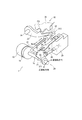
- FIG. 1 is a perspective view illustrating a shift-by-wire system according to an embodiment.
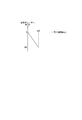
- FIG. 2 is a schematic diagram illustrating a shift-by-wire system according to an embodiment.
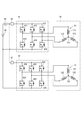
- FIG. 3 is a circuit diagram illustrating a motor and a motor driver according to an embodiment.
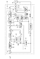
- FIG. 4 is a block diagram illustrating a shift range control apparatus according to an embodiment.
- FIG. 5 is an explanatory diagram illustrating target speed setting according to an embodiment.
- FIG. 6A is an explanatory diagram illustrating FF duty during acceleration control according to an embodiment
- FIG. 6B is an explanatory diagram illustrating the FF duty during normal control according to an embodiment.
- FIG. 6C is an explanatory diagram illustrating FF duty during deceleration control according to an embodiment.
- FIG. 7 is an explanatory diagram illustrating a fixed duty according to an embodiment.
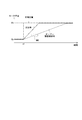
- FIG. 8A is a time chart illustrating open drive control according to an embodiment.
- FIG. 8B is an enlarged view of the VIIIB portion of FIG. 8A.
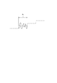
- FIG. 9 is a time chart for explaining the duty at the time of open drive control according to an embodiment.
- FIG. 10 is an explanatory diagram showing the relationship between the battery voltage and the abnormal duty according to one embodiment.
- FIG. 11 is an explanatory diagram showing the relationship between the battery voltage and the duty gradient according to one embodiment.
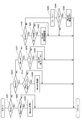
- FIG. 12 is a flowchart illustrating shift-by-wire control processing according to an embodiment.
- FIG. 12 is a flowchart illustrating shift-by-wire control processing according to an embodiment.
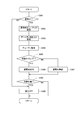
- FIG. 13 is a flowchart for explaining normal-time control processing according to an embodiment.
- FIG. 14 is a flowchart illustrating mode determination processing according to an embodiment.
- FIG. 15 is a flowchart illustrating a PWM control process according to an embodiment.
- FIG. 16 is a flowchart for explaining an abnormal time control process according to an embodiment.
- FIG. 17 is a flowchart illustrating an abnormality determination process according to an embodiment.
- FIGS. 1 and 2 A shift range control apparatus according to one embodiment is shown in FIGS.
- the shift-by-wire system 1 that is a shift range switching system includes a motor 10, a shift range switching mechanism 20, a parking lock mechanism 30, a shift range control device 40, and the like.
- the motor 10 rotates when power is supplied from a battery 45 (see FIG. 3) mounted on a vehicle (not shown), and functions as a drive source for the shift range switching mechanism 20.
- the motor 10 of this embodiment is a permanent magnet type DC brushless motor.
- the motor 10 has two winding sets 11 and 12.
- the first winding set 11 includes a U1 coil 111, a V1 coil 112, and a W1 coil 113.
- the second winding set 12 includes a U2 coil 121, a V2 coil 122, and a W2 coil 123.
- the encoder 13 as a rotation angle sensor detects the rotational position of a rotor (not shown) of the motor 10.
- the encoder 13 is, for example, a magnetic rotary encoder, and includes a magnet that rotates integrally with the rotor, a Hall IC for magnetic detection, and the like.
- the encoder 13 outputs A-phase and B-phase pulse signals at every predetermined angle in synchronization with the rotation of the rotor.
- the reducer 14 is provided between the motor shaft, which is the rotation shaft of the motor 10, and the output shaft 15, and decelerates the rotation of the motor 10 and outputs it to the output shaft 15. Thereby, the rotation of the motor 10 is transmitted to the shift range switching mechanism 20.
- the output shaft 15 is provided with an output shaft sensor 16 that detects the angle of the output shaft 15.
- the output shaft sensor 16 is, for example, a potentiometer.
- the shift range switching mechanism 20 includes a detent plate 21, a detent spring 25, and the like.
- the rotational driving force output from the speed reducer 14 is converted into a manual valve 28 and a parking lock mechanism 30.
- the detent plate 21 is fixed to the output shaft 15 and is driven by the motor 10.
- the direction in which the detent plate 21 moves away from the base portion of the detent spring 25 is defined as the forward rotation direction, and the direction approaching the base portion is defined as the reverse rotation direction.
- the detent plate 21 is provided with pins 24 that protrude in parallel with the output shaft 15.
- the pin 24 is connected to the manual valve 28.
- the shift range switching mechanism 20 converts the rotational motion of the motor 10 into a linear motion and transmits it to the manual valve 28.
- the manual valve 28 is provided on the valve body 29.
- a hydraulic pressure supply path to a hydraulic clutch (not shown) is switched, and the shift range is changed by switching the engagement state of the hydraulic clutch.
- On the detent spring 25 side of the detent plate 21 four concave portions 22 are provided for holding the manual valve 28 at a position corresponding to each range.
- the recess 22 corresponds to each of the D, N, R, and P ranges from the base side of the detent spring 25.
- the detent spring 25 is an elastically deformable plate-like member, and a detent roller 26 is provided at the tip.
- the detent roller 26 is fitted into one of the recesses 22.
- the detent spring 25 biases the detent roller 26 toward the rotation center side of the detent plate 21.
- the detent spring 25 is elastically deformed and the detent roller 26 moves in the recess 22.
- the swing of the detent plate 21 is restricted, the axial position of the manual valve 28 and the state of the parking lock mechanism 30 are determined, and the automatic transmission 5 The shift range is fixed.
- the parking lock mechanism 30 includes a parking rod 31, a cone 32, a parking lock pole 33, a shaft portion 34, and a parking gear 35.
- the parking rod 31 is formed in a substantially L shape, and one end 311 side is fixed to the detent plate 21.
- a conical body 32 is provided on the other end 312 side of the parking rod 31.
- the cone 32 is formed so as to decrease in diameter toward the other end 312 side.
- the parking lock pole 33 is in contact with the conical surface of the cone 32 and is provided so as to be able to swing around the shaft portion 34.
- a convex portion that can mesh with the parking gear 35. 331 is provided on the parking gear 35 side of the parking lock pole 33.
- the parking gear 35 is provided on an axle (not shown) and is provided so as to be able to mesh with the convex portion 331 of the parking lock pole 33.
- rotation of the axle is restricted.
- the shift range is a notP range that is a range other than P
- the parking gear 35 is not locked by the parking lock pole 33, and the rotation of the axle is not hindered by the parking lock mechanism 30.
- the shift range is the P range
- the parking gear 35 is locked by the parking lock pole 33 and the rotation of the axle is restricted.
- the shift range control device 40 includes motor drivers 41 and 42 as driver circuits, an ECU 50, and the like.
- the motor driver 41 is a three-phase inverter that switches energization of the first winding set 11, and switching elements 411 to 416 are bridge-connected.
- One end of the U1 coil 111 is connected to a connection point between the U-phase switching elements 411 and 414 that form a pair.
- One end of the V1 coil 112 is connected to a connection point between the paired V-phase switching elements 412 and 415.
- One end of the W1 coil 113 is connected to a connection point between the paired W-phase switching elements 413 and 416.
- the other ends of the coils 111 to 113 are connected by a connection part 115.
- the motor driver 42 is a three-phase inverter that switches energization of the second winding set 12, and switching elements 421 to 426 are bridge-connected.
- One end of the U2 coil 121 is connected to a connection point between the U-phase switching elements 421 and 424 that form a pair.
- One end of the V2 coil 122 is connected to a connection point between the paired V-phase switching elements 422 and 425.
- One end of the W2 coil 123 is connected to a connection point between the paired W-phase switching elements 423 and 426.
- the other ends of the coils 121 to 123 are connected by a connection part 125.
- the switching elements 411 to 416 and 421 to 426 of the present embodiment are MOSFETs, but other elements such as IGBTs may be used.
- a motor relay 46 is provided between the motor driver 41 and the battery 45.
- a motor relay 47 is provided between the motor driver 42 and the battery 45.
- the motor relays 46 and 47 are turned on when a start switch such as an ignition switch is turned on, and power is supplied to the motor 10 side. Further, the motor relays 46 and 47 are turned off when the start switch is turned off, and the supply of electric power to the motor 10 side is cut off.
- a voltage sensor 48 for detecting the battery voltage Vb is provided on the high potential side of the battery 45.
- the battery voltage Vb corresponds to the “input voltage”.
- the shift range control device 40 is provided with a current sensor (not shown) that detects the motor current Im.
- the ECU 50 controls the driving of the motor 10 by controlling the on / off operation of the switching elements 411 to 416 and 421 to 426. Further, the ECU 50 controls driving of the shift hydraulic control solenoid 6 based on the vehicle speed, the accelerator opening, the state of the brake switch, the driver request shift range, and the like. The gear position is controlled by controlling the shift hydraulic control solenoid 6.
- the number of shift hydraulic control solenoids 6 is provided according to the number of shift stages. In the present embodiment, one ECU 50 controls the driving of the motor 10 and the solenoid 6, but the motor ECU for controlling the motor 10 and the AT-ECU for solenoid control may be separated.
- the drive control of the motor 10 will be mainly described.
- the ECU 50 includes a normal-time control unit 51, an abnormality determination unit 81, an abnormal-time control unit 82, a signal switching unit 83, and the like, and is configured mainly with a microcomputer or the like.
- Each process in the ECU 50 may be a software process by a CPU executing a program stored in advance in a substantial memory device such as a ROM, or may be a hardware process by a dedicated electronic circuit.
- the normal time control unit 51 includes an angle calculation unit 52, a speed calculation unit 53, an angle deviation calculation unit 54, a feedback control unit 60, a sudden brake duty calculation unit 70, a duty switching unit 71, a voltage correction unit 72, and a PWM signal generation unit 73. , Stationary phase energization control unit 75, inversion determination unit 76, and normal signal output unit 77.
- the angle calculation unit 52 calculates the actual count value Cen that is the count value of the encoder 13 based on the A-phase and B-phase pulses output from the encoder 13.
- the actual count value Cen is a value corresponding to the actual mechanical angle and electrical angle of the motor 10. That is, the actual count value Cen is a value that can be converted into the actual motor angle ⁇ m.
- the speed calculation unit 53 calculates a motor speed Msp that is the rotation speed of the motor 10 based on the actual count value Cen.
- the angle deviation calculator 54 calculates the difference between the target count value Cen * and the actual count value Cen according to the driver request shift range input by operating a shift lever (not shown).
- the absolute value of the difference between the target count value Cen * and the actual count value Cen is referred to as an angle deviation e.
- the actual count value Cen can be regarded as “actual angle”
- the target count value Cen * can be regarded as “target angle”.
- the feedback control unit 60 includes a target speed setting unit 62, a feedback value setting unit 63, a speed deviation calculation unit 64, a controller 65, a feedforward term calculation unit 66, an adder 67, and the like.
- feedback is described as “FB”
- feedforward is described as “FF”.
- the target speed setting unit 62 calculates a target motor speed Msp * that is a target speed of the motor 10 based on the angle deviation e. For example, based on the map shown in FIG. 5, the target motor speed Msp * is set so as to increase as the angle deviation e is larger when the angle deviation e is equal to or smaller than the predetermined value ea, and when the angle deviation e is larger than the predetermined value ea. , And a predetermined maximum value. Further, the angle deviation e is set to a set speed sp1 (for example, 1000 rpm) at the angle determination threshold value e_th. The target motor speed Msp * is set so as to increase as the battery voltage Vb increases.
- a set speed sp1 for example, 1000 rpm
- the FB value setting unit 63 performs phase advance compensation to advance the phase of the motor speed Msp when the control state of the motor 10 is mode 2 or mode 3 described later, that is, steady control or deceleration control, and sets the speed phase advance value Msp_pl.
- the speed feedback value is Msp_fb.
- the FB value setting unit 63 does not perform phase advance compensation and sets the motor speed Msp as the speed feedback value Msp_fb.
- the speed phase advance value Msp_pl is also included in the concept of “motor speed”.
- the speed deviation calculator 64 calculates a speed deviation ⁇ Msp between the target motor speed Msp * and the speed feedback value Msp_fb.
- the controller 65 calculates the FB duty D_fb by, for example, P control or PI control so that the speed deviation ⁇ Msp becomes 0 so that the target motor speed Msp * matches the speed feedback value Msp_fb.
- the FF term calculation unit 66 calculates the FF duty D_ff corresponding to the control state of the motor 10.
- the FF duty D_ff at the time of acceleration control is the maximum acceleration duty calculated based on the map shown in FIG. 6A and the like, and increases as the motor speed Msp increases.
- the FF duty D_ff is calculated so that the maximum duty is obtained until the motor speed Msp becomes equal to or higher than the target motor speed Msp * .
- the FF duty D_ff during steady control is a speed maintenance duty calculated based on the map shown in FIG. 6B and the like.
- the speed maintenance duty is a duty for maintaining the motor speed Msp when there is no load, and increases as the motor speed Msp increases.
- the FF duty D_ff at the time of deceleration control is a deceleration correction duty calculated based on the map shown in FIG. 6C and the like.
- the deceleration correction duty is a correction duty for realizing the target motor speed Msp * .
- the deceleration correction duty is a negative value when the motor 10 is rotating in the positive direction, and decreases as the motor speed Msp increases. In other words, the deceleration correction duty increases as the absolute value as the motor speed Msp increases.
- 6A, 6B, and 6C are cases where the motor 10 is rotating in the forward rotation direction, and when the motor 10 is rotating in the reverse rotation direction, the value of the FF duty D_ff is reversed.
- the FF duty D_ff is calculated based on the motor speed Msp.
- the FF duty D_ff may be calculated based on the target motor speed Msp * instead of the motor speed Msp.
- the adder 67 adds the FB duty D_fb and the FF duty D_ff, and calculates the corrected FB duty Da.
- the magnitude of the current and torque flowing in the coils 111 to 113 and 121 to 123 can be changed by changing the duty by PWM control or the like.
- the motor 10 is driven by so-called 120 ° energization that turns on the first-phase high-potential side switching element and the second-phase low-potential side switching element.
- the energized phase is switched by switching the combination of the first phase and the second phase every 60 ° electrical angle. Thereby, a rotating magnetic field is generated in the winding sets 11 and 12, and the motor 10 rotates.
- the rotation direction of the motor 10 when the output shaft 15 is rotated in the positive rotation direction is the positive direction.
- the duty when the motor 10 outputs a positive torque is positive
- the duty when the negative torque is output is negative
- a possible duty range is ⁇ 100 [%] to 100 [%]. That is, when the motor 10 is rotated forward, the duty is positive, and when the motor 10 is rotated reversely, the duty is negative.
- brake torque that is, negative torque
- the rotation direction of the motor 10 is the positive rotation direction, but the duty is negative.
- the brake torque is generated to stop the motor 10 that is rotating in the reverse direction, the duty is positive.
- the sudden brake duty calculation unit 70 sets the fixed duty Db, which is the duty at the time of sudden brake control, to the rush speed Msp_i that is the motor speed Msp when the sudden brake control is started, that is, when the angle deviation e becomes smaller than the angle determination threshold e_th. Calculate according to. As shown in FIG. 7, the fixed duty Db when the motor 10 is rotating forward is a negative value, and when the rush speed Msp_i is smaller than the predetermined speed sp2, the absolute value increases as the rush speed Msp_i increases. When the speed is equal to or higher than the predetermined speed sp2, it is set to ⁇ 100 [%].
- the duty switching unit 71 switches whether the duty used for signal generation is the corrected FB duty Da or the fixed duty Db. In the present embodiment, when the angle deviation e is equal to or greater than the angle determination threshold e_th, the corrected FB duty Da is selected. When the angle deviation e is smaller than the angle determination threshold e_th, the fixed duty Db is selected as the duty used for signal generation, and the voltage The data is output to the correction unit 72.
- the voltage correction unit 72 corrects the selected corrected FB duty Da or fixed duty Db with the battery voltage Vb, and calculates a duty command value.
- the PWM signal generation unit 73 generates a command signal Spwm related to switching of the switching elements 411 to 416 and 421 to 426 based on the duty command value and the actual count value Cen. Further, the command signal Spwm is adjusted so that the motor current Im does not exceed the current limit value Im_max.
- the stationary phase energization control unit 75 performs stationary phase energization control.
- the stationary phase energization control is a control for stopping the rotation of the motor 10, and selects a stationary phase according to the electrical angle, so that the current flows in a predetermined direction of the selected stationary phase.
- Command signals Sfix relating to switching of 416 and 421 to 426 are generated. Thereby, the excitation phase is fixed.
- the motor 10 stops at a predetermined electrical angle corresponding to the excitation phase.
- the stationary phase energization control unit 75 selects the stationary phase and the energization direction based on the actual count value Cen so as to stop the motor 10 at the closest electrical angle from the current rotor position.
- the stationary phase energization control is continued for the stationary phase energization duration Ta.
- the duty in the fixed phase energization period in which the fixed phase energization control is performed is constant at the maximum duty. Further, the first period from the start until the predetermined time elapses is set as the maximum duty, and the motor current at the end of the fixed phase energization control is 0 in the second period after the predetermined time elapses until the stationary phase energization control is terminated.
- the duty may be gradually changed.
- the duty of the second period may be a predetermined value whose absolute value is smaller than the maximum duty.
- the vibration of the motor shaft when the energization is turned off from the stationary phase energization control can be suppressed, and the output shaft 15 is stopped at a desired position. Can be maintained appropriately.
- the inversion determination unit 76 determines whether or not the rotation of the motor 10 is inverted based on the actual count value Cen.
- the normal signal output unit 77 switches signals output to the motor drivers 41 and 42 during normal control. In the present embodiment, when the motor 10 is rotating in the rotation direction corresponding to the required shift range, that is, before inversion, the command signal Spwm generated by the PWM signal generation unit 73 is selected, and the motor 10 Is reversed, the command signal Sfix generated by the stationary phase energization control unit 75 is selected.
- the abnormality determination unit 81 monitors the abnormality of the encoder 13.
- the abnormality determination unit 81 determines that an abnormality has occurred in the encoder 13 when the actual count value Cen does not change over the abnormality continuation time Te during motor energization.
- the abnormality of the encoder 13 includes not only the abnormality of the encoder 13 itself but also the disconnection of the wiring connected to the encoder 13.
- the abnormal time control unit 82 performs open drive control for directly controlling the energized phase without using the actual count value Cen as the abnormal time control. In the open drive control, on / off of the switching elements 411 to 416 and 421 to 426 is controlled so that the energized phase is switched every predetermined energized phase switching period Pc (for example, 5 [ms]).
- the signal switching unit 83 switches signals to be output to the motor drivers 41 and 42 according to the abnormality determination result of the abnormality determination unit 81. Specifically, when the encoder 13 is normal, the signal selected by the normal signal output unit 77 is output to the motor drivers 41 and 42. When the encoder 13 is abnormal, a signal generated by the abnormality control unit 82 is output to the motor drivers 41 and 42.
- FIG. 8A the shift range before time x1 is the P range, and the motor angle at this time is ⁇ p.
- the driver requested shift range is switched from the P range to the D range at time x1
- the target position of the motor angle ⁇ m is set to the angle ⁇ d, as indicated by a dashed line.
- the encoder 13 is normal, as shown by the solid line, by driving the motor 10 by feedback control using the actual count value Cen, the motor 10 is quickly rotated to the angle ⁇ d.
- the motor 10 is rotated to the angle ⁇ d by open drive control without using the actual count value Cen.
- the open drive control as shown by a broken line, the motor 10 is rotated to an angle ⁇ d over time from the normal time so as to suppress vibration of the motor 10.
- FIG. 8B is an enlarged view of the portion VIIIB in FIG. 8A.
- the theoretical motor angle ⁇ m by switching the energized phase is indicated by a broken line
- the motor angle ⁇ m when the open drive control is performed at a duty of 100% is indicated by a solid line.
- the motor angle ⁇ m at the time of open driving with a duty of 100% is shown for one time of the energized phase switching period Pc.
- the motor 10 is driven stepwise by switching the energized phase every energized phase switching period Pc.
- a DC brushless motor having a larger torque than the SR motor is used as the motor 10.
- step out the fact that the vibration of the motor 10 is large and the drive of the motor 10 cannot be appropriately controlled is referred to as “step out”.
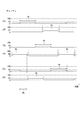
- FIG. 9 shows the duty during open drive control in this embodiment.
- a switching element 411 that is a U-phase upper arm element
- a switching element 414 that is a U-phase lower arm element
- a switching element 412 that is a V-phase upper arm element
- a switching element that is a V-phase lower arm element 415 duty in open drive control of switching element 413 which is a W-phase upper arm element and switching element 416 which is a W-phase lower arm element.
- the U-phase upper arm element is omitted as “U”. Since the switching patterns of the switching elements 421 to 426 of the motor driver 42 are the same as those of the motor driver 41, description thereof is omitted.
- the motor drivers 41 and 42 may have an energization phase difference.
- the energized phase switching period Pc is described for only one cycle in order to avoid complication.
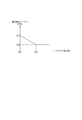
- the abnormal duty Df during the open drive control is made smaller than 100%.
- the abnormal duty Df is set according to the battery voltage Vb. Specifically, when the normal lower limit value Vb1 of the battery voltage Vb is set to a value Df1 smaller than 100%, and the battery voltage Vb is smaller than the predetermined voltage Vb2, the duty Df at the time of abnormality decreases as the battery voltage Vb increases. Become. When the battery voltage Vb is equal to or higher than the predetermined voltage Vb2, the abnormality duty Df is set to a predetermined value Df2 (for example, 30%).
- the switching elements 411 and 415 are turned on and the UV phase energization in which a current flows from the U1 coil 111 to the V1 coil 112, the switching elements 411 and 415 The on / off operation is controlled so as to be Df.
- the duty Df By making the duty Df smaller than 100% at the time of abnormality, the energization amount can be suppressed as compared with the case where the duty is set to 100% and the switching elements 411 and 415 are kept on.
- the energized amount can be suppressed compared to the case where the on-off operation is continued. Thereby, the vibration of the motor 10 is suppressed and step-out can be prevented.
- the duty is gradually changed at the start and end of the energization continuation period Pk. Specifically, at the start of the energization continuation period Pk, the duty is gradually increased so that the abnormal duty Df set according to the battery voltage Vb is obtained. Further, at the end of the energization continuation period Pk, the duty is gradually decreased so as to become zero.
- the duty change amount per unit time when the duty is gradually changed at the start and end of the energization continuation period Pk is defined as a duty gradient ⁇ D.
- Duty gradient ⁇ D is set according to battery voltage Vb. Specifically, the absolute value of the duty slope ⁇ D is the maximum value ⁇ D1 when the normal lower limit value Vb1 of the battery voltage Vb is reached. When the battery voltage Vb is smaller than the predetermined voltage Vb3, the duty slope ⁇ D increases as the battery voltage Vb increases. The absolute value of becomes smaller. When the battery voltage Vb is equal to or higher than the predetermined voltage Vb3, the absolute value of the duty gradient ⁇ D is set to a predetermined value ⁇ D2.
- the predetermined voltages Vb2 and Vb3 may be the same value or different values.
- the absolute value of the duty gradient ⁇ D may be different at the start and end of the energization continuation period Pk using different maps. 10 and FIG. 11, the example in which the abnormal duty Df and the duty gradient ⁇ D linearly decrease as the battery voltage Vb increases has been described. May be reduced.
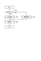
- step S100 step S100 is omitted, and is simply referred to as “S”. The same applies to the other steps.
- the encoder abnormality flag is “X_FAIL”, the state where the encoder abnormality flag is set is “1”, and the state where the encoder abnormality flag is not set is “0”.
- S100: NO the process proceeds to S200, and the ECU 50 performs normal control.
- S300 the ECU 50 performs abnormality control.
- S400 which proceeds from S200 or S300, the ECU 50 performs an abnormality determination process.
- Mode 1 is “acceleration control”, in which the rotation of the motor 10 is accelerated.
- Mode 2 is “steady control”, and the rotational speed of the motor 10 is kept substantially constant.
- Mode 3 is “deceleration control”, in which the rotation of the motor 10 is decelerated.
- Mode 4 is “sudden brake control”, in which the motor 10 is suddenly braked.
- Mode 5 is “fixed phase energization control”, and the motor 10 is stopped.
- Mode 0 is “energization off control”, and energization of the motor 10 is stopped.
- the ECU 50 determines whether or not the driver request shift range has changed. When it is determined that the driver request shift range has not changed (S201: NO), the process proceeds to S203. When it is determined that the driver request shift range has changed (S201: YES), the process proceeds to S202.
- the ECU 50 turns on an energization flag for the motor 10. Further, the ECU 50 sets the control state to mode 1 that is acceleration control.
- the ECU 50 determines whether or not the energization flag is turned on. When it is determined that the energization flag is off (S203: NO), the process proceeds to S210. When it is determined that the energization flag is on (S203: YES), the process proceeds to S204.
- the target speed setting unit 62 sets the target motor speed Msp * .
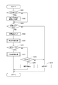
- the normal time control unit 51 performs a mode determination process.
- the normal time control unit 51 determines whether or not the control mode is mode 1. When it is determined that the control mode is not mode 1 (S251: NO), the process proceeds to S254. When it is determined that the control mode is mode 1 (S251: YES), the process proceeds to S252.
- the normal time control unit 51 determines whether or not the target motor speed Msp * is smaller than the current motor speed Msp. When it is determined that the target motor speed Msp * is equal to or higher than the current motor speed Msp (S252: NO), the mode 1 is continued. When it is determined that the target motor speed Msp * is lower than the current motor speed Msp (S252: YES), the process proceeds to S253. In S253, the normal time control unit 51 sets the control mode to mode 2 which is steady control.
- the normal time control unit 51 determines whether or not the control mode is mode 2. When it is determined that the control mode is not mode 2 (S254: NO), the process proceeds to S257. When it is determined that the control mode is mode 2 (S254: YES), the process proceeds to S255.
- the normal time control unit 51 determines whether or not the current value Msp * (n) of the target motor speed is smaller than the previous value Msp * (n ⁇ 1). When it is determined that the target motor speed Msp * (n) is equal to or higher than the previous value Msp * (n ⁇ 1) (S255: NO), the mode 2 is continued. When it is determined that the target motor speed Msp * (n) is smaller than the previous value Msp * (n ⁇ 1) (S255: YES), the process proceeds to S256. In S256, the normal time control unit 51 sets the control mode to mode 3 that is deceleration control.
- the normal time control unit 51 determines whether or not the control mode is mode 3. When it is determined that the control mode is not mode 3 (S257: NO), the process proceeds to S260. When it is determined that the control mode is mode 3 (S257: YES), the process proceeds to S258.
- the normal time control unit 51 determines whether or not the angle deviation e is smaller than the angle determination threshold value e_th. When it is determined that the angle deviation e is equal to or greater than the angle determination threshold e_th (S258: NO), the mode 3 is continued. When it is determined that the angle deviation e is smaller than the angle determination threshold e_th (S258: YES), the process proceeds to S259. In S259, the normal time control unit 51 sets the control mode to the mode 4 that is the sudden brake control.
- the normal time control unit 51 determines whether the control mode is mode 4 or not. When it is determined that the control mode is not mode 4 (S260: NO), the process proceeds to S263. When it is determined that the control mode is mode 4 (S260: YES), the process proceeds to S261.
- the reversal determination unit 76 determines whether or not the motor 10 has been reversed. Here, if the motor 10 rotates in the direction opposite to the rotation direction determined based on the range before and after the shift range is switched, it is determined that the motor 10 is reversed. When it is determined that the motor 10 is not reversed (S261: NO), the mode 4 is continued. When it is determined that the motor 10 has been reversed (S261: YES), the process proceeds to S262. In S262, the normal time control unit 51 sets the control mode to mode 5 which is stationary phase energization control.
- the control mode is mode 5
- the normal time control unit 51 measures the duration of the fixed-phase energization control.
- the timer value Tc that is the count value of the timer to be incremented is incremented.
- ECU 50 determines whether or not timer value Tc is greater than duration determination threshold Tth.
- the duration determination threshold value Tth is a value set according to a stationary phase energization duration Ta (for example, 100 ms) for which the stationary phase energization control is continued.
- the mode 5 is continued.
- the process proceeds to S265.
- the normal time control unit 51 sets the control mode to mode 0 which is energization-off control.
- the normal time control unit 51 determines whether or not the control mode is any one of modes 1 to 4.
- the control mode is modes 1 to 4
- the motor 10 is PWM-controlled.
- S206: NO the process proceeds to S208.
- S206: YES the process proceeds to S207.
- the normal time control unit 51 controls driving of the motor 10 by PWM control.
- the PWM control will be described based on FIG.
- the normal time control unit 51 determines whether or not the control mode is any one of modes 1 to 3.
- the control mode is modes 1 to 3
- the motor 10 is feedback-controlled.
- mode 4 mode 4
- the process proceeds to S278.
- the control mode is any one of modes 1 to 3 (S271: YES)
- the process proceeds to S272.
- the normal time control unit 51 determines whether or not the control mode is mode 1. When it is determined that the control mode is mode 1 (S272: YES), the process proceeds to S273. When it is determined that the control mode is not mode 1, that is, mode 2 or mode 3 (S272: NO), the process proceeds to S274.
- the feedback value setting unit 63 outputs the motor speed Msp to the speed deviation calculation unit 64 as the speed feedback value Msp_fb.
- the feedback value setting unit 63 outputs the phase advance compensation value Msp_pl of the motor speed Msp to the speed deviation calculation unit 64 as the speed feedback value Msp_fb.
- the controller 65 calculates the feedback duty D_fb.
- the feedforward term calculation unit 66 calculates the feedforward duty D_ff corresponding to the control mode.
- the adder 67 adds the feedback duty D_fb and the feedforward duty D_ff, and calculates the corrected feedback duty Da.
- the sudden brake duty calculation unit 70 sets the fixed duty Db according to the inrush speed Msp_i.
- the fixed duty Db is set, the set value is maintained.
- the PWM signal generation unit 73 generates the command signal Spwm based on the calculated corrected feedback duty Da or fixed duty Db.
- the ECU 50 controls driving of the motor 10 based on the generated command signal Spwm.
- the normal time control unit 51 determines whether or not the control mode is mode 5. When it is determined that the control mode is mode 5 (S208: YES), the process proceeds to S209. When it is determined that the control mode is not mode 5 (S208: NO), that is, when the control mode is mode 0, the process proceeds to S210.
- the normal time control unit 51 performs fixed phase energization control. Specifically, the stationary phase energization control unit 75 generates a command signal Sfix that energizes the stationary phase according to the actual count value Cen. The ECU 50 controls the driving of the motor 10 based on the generated command signal Sfix. In S210, the ECU 50 turns off the power supply to the motor 10.
- the abnormality control process in S300 will be described based on the flowchart of FIG.
- the abnormal time control process the elapsed time from the start of the abnormal time control process is measured.
- the abnormal time control unit 82 determines whether the motor 10 is energized. Whether or not power is being supplied is determined based on, for example, a power supply flag. When it is determined that power is not being supplied (S301: NO), the process proceeds to S309. When it is determined that power is being supplied (S301: YES), the process proceeds to S302.
- the abnormality control unit 82 sets the abnormality duty Df based on the battery voltage Vb. In S303, the abnormality control unit 82 sets the duty gradient ⁇ D based on the battery voltage Vb. In S304, the abnormality control unit 82 sets the duty of each phase according to the elapsed time from the start of the abnormality control process.
- the abnormal time control unit 82 determines whether it is the switching timing of the energized phase based on the elapsed time from the start of the abnormal time control process. When it is determined that it is the switching timing of the energized phase (S305: YES), the process proceeds to S306. When it is determined that it is not the switching timing of the energized phase (S305: NO), the process proceeds to S307.
- the abnormality control unit 82 switches the energized phase. Specifically, the duty is gradually changed so that the duty of the switching element that switches from the OFF state to the ON state becomes the abnormal duty Df with the duty gradient ⁇ D. Further, the duty of the switching element that switches from the on state to the off state is gradually changed so that the duty of the switching element becomes 0 at the inclination ⁇ D.
- the abnormality control unit 82 continues the current energized phase without switching the energized phase. Specifically, the switching element to be controlled is not changed, and the on / off operation at the abnormality time duty Df set in S302 is continued.
- the abnormal time control unit 82 determines whether or not the motor 10 has rotated to the target position. Since the count value of the encoder 13 cannot be used in the abnormal time control process, the determination is made based on the count value of the number of switching of the energized phase, the elapsed time from the start of the abnormal time control process, or the like. When it is determined that the motor 10 has not rotated to the target position (S308: NO), the process of S309 is not performed. When it is determined that the motor 10 has rotated to the target position (S308: YES), the process proceeds to S309. In S309, the ECU 50 turns off the energization of the motor 10. If the energization of the motor 10 is off, the energization off is continued.
- the abnormality determination unit 81 determines whether the motor 10 is energized. Whether or not power is being supplied is determined based on, for example, a power supply flag, similarly to the determination in S301. When it is determined that power is not being supplied (S401: NO), the processing after S402 is not performed. When it is determined that power is being supplied (S401: YES), the process proceeds to S402.
- the abnormality determination unit 81 determines whether or not the actual count value Cen of the encoder 13 has changed within the abnormality continuation time Te. When it is determined that the actual count value Cen has changed within the abnormal continuation time Te (S402: YES), the process proceeds to S403. When it is determined that the actual count value Cen has not changed over the abnormal continuation time Te (S402: NO), the process proceeds to S404. In S403, the abnormality determination unit 81 resets the encoder abnormality flag. In S404, the abnormality determination unit 81 sets an encoder abnormality flag.
- the energization amount to the motor 10 can be suppressed as compared with the case where the duty is set to 100%. Thereby, the vibration of the motor 10 is suppressed, and the motor 10 can be appropriately rotated to the target position corresponding to the required shift range without stepping out. Further, by gradually changing the duty at the time of switching the energized phase, a sudden change in current accompanying switching of the energized phase is suppressed. Thereby, the vibration of the motor 10 due to the switching of the energized phase is suppressed, and the motor 10 can be appropriately rotated to the target position corresponding to the required shift range without stepping out.
- the shift range control device 40 of the present embodiment controls the shift range by switching the shift range by controlling the on / off operation of the switching elements 411 to 416 and 421 to 426 of the motor drivers 41 and 42.
- the range control device includes an abnormality determination unit 81, a normal control unit 51, and an abnormal control unit 82.
- the abnormality determination unit 81 detects an abnormality of the encoder 13 that detects the rotation angle of the motor 10.
- the normal time control unit 51 controls the driving of the motor 10 using the detection value of the encoder 13.
- the abnormal-time control unit 82 When the encoder 13 is abnormal, the abnormal-time control unit 82 performs open drive control that is an abnormal-time control that switches the energized phase every energized phase switching period Pc without using the detection value of the encoder 13.
- the abnormal-time control unit 82 provides a current reduction period with a duty smaller than 100% in at least a part of the energization continuation period Pk in which energization in the same direction is continued in one phase.
- the U-phase switching element 411 is on and the 414 is off, the U1 coil 111 is continuously energized in the direction of flowing into the connection part 115.
- the duty is 100%
- the ON state of the switching element 411 is continued over the energization continuation period Pk.
- the duty is made smaller than 100%, and the period during which the switching element 411 is turned off is provided, whereby the current is reduced as compared with the case where the duty is 100%.
- the abnormal time control unit 82 sets the duty to an abnormal time duty Df smaller than 100% in the entire energization duration Pk. Thereby, since an electric current can be suppressed over energization continuation period Pk, the vibration of the motor 10 can be suppressed appropriately.
- the abnormal duty Df is variable according to the battery voltage Vb. Thereby, the vibration of the motor 10 can be more appropriately suppressed according to the battery voltage Vb.
- the abnormal time control unit 82 gradually changes the duty of the switching elements 411 to 416 and 421 to 426 to be switched from the off state to the on state from 0 to a predetermined duty at the start of the energization continuation period Pk.
- the duty is gradually changed to the abnormal duty Df.
- the abnormal time control unit 82 gradually changes the duty of the switching elements 411 to 416 and 421 to 426 to switch from the on state to the off state to 0 at the end of the energization continuation period Pk.
- the “ON state” means a state in which ON / OFF is repeated with a predetermined duty. If the duty is 100%, the corresponding switching elements 411 to 416 and 421 to 426 are kept on.
- the duty gradient ⁇ D when the duty gradually changes at the start or end of the energization duration is variable according to the battery voltage Vb. Thereby, the vibration of the motor 10 can be more appropriately suppressed according to the battery voltage Vb.
- the duty over the entire energization continuation period is set to an abnormality duty less than 100%, and the duty is gradually changed at the start and end of the energization continuation period.
- the duty at the start of the energization duration period is not gradually changed, At the start, the duty may be the abnormal duty.
- the duty at the end of the energization duration may not be gradually changed, and the duty may be set to 0 as the energization duration ends. .
- the duty of the period other than the duty gradual change is set to 100%, and the corresponding switching element is continuously turned on. Also good.
- the period during which the duty is gradually changed is the current reduction period. Even if it does in this way, in the control at the time of abnormality, since the electric current reduction period with a duty smaller than 100% is provided in at least a part of the energization continuation period, the entire energization period is energized with a duty of 100%. The amount of energization is reduced more than sometimes. Thereby, the vibration of the motor is suppressed, and the motor 10 can be rotated to the target position without stepping out.
- the abnormal duty is variable according to the input voltage. In another embodiment, the abnormal duty may be a predetermined value regardless of the input voltage. In the above embodiment, the duty gradient at the start and end of the energization continuation period is variable according to the input voltage. In another embodiment, the duty gradient at the start and end of energization start may be a predetermined value regardless of the input voltage. In the above embodiment, the input voltage is a battery voltage. In another embodiment, any value other than the battery voltage may be used as long as it is a value related to the voltage input to the motor driver.
- the energized phase switching period is constant. In another embodiment, the energized phase switching period may be longer before the predetermined number of times from the start of the abnormal time control than after the predetermined number of energized phase switching. By lengthening the energized phase switching period immediately after the start of the abnormal time control where the motor vibration is more likely to occur, the vibration of the motor at the start of the abnormal time control can be appropriately suppressed.
- the motor is a permanent magnet type three-phase brushless motor. In other embodiments, the motor is not limited to a three-phase brushless motor, and any motor may be used. In the above embodiment, the motor is provided with two winding sets. In another embodiment, the number of winding sets of the motor may be one or more than three.
- the normal control in the normal control, the detected value of the rotation angle sensor is used, the target speed is set based on the angle deviation, and the drive of the motor is controlled by speed feedback control. In addition, the motor is stopped at the target position by switching from speed feedback control to sudden brake control and stationary phase energization control.
- the normal control may be any control as long as it uses control values detected by the rotation angle sensor.
- the drive of the motor is controlled by so-called 120 ° energization.
- control other than 120 ° energization may be performed.
- a so-called 180 ° energization may be used.
- PWM control by a triangular wave comparison method or an instantaneous vector selection method may be used.
- the phase lead value subjected to the phase lead filter process is fed back.
- a value obtained by performing the phase advance filter process may be fed back even when the speed state is acceleration control.
- the phase advance filter process in at least one of the steady state and the deceleration state may be omitted.
- the determination of the speed state is not limited to the method of the above-described embodiment, and any method may be used, for example, determination using a differential value of the motor speed.
- switching from feedback control to sudden braking control with a fixed duty is determined using one angle determination threshold value.
- the angle determination threshold value may be variable according to the motor speed, for example, the angle determination threshold value is increased as the motor speed increases.
- the fixed duty in the sudden brake control is set according to the inrush speed.
- the fixed duty may be a predetermined value (for example, maximum duty) regardless of the rush speed.
- the duty until the fixed duty time elapses is the maximum duty.
- the duty until the fixed duty time in the fixed phase energization control does not have to be the maximum duty.
- the duty changing process in the fixed phase energization control may be omitted, and the duty during the fixed phase energization may be constant.
- an encoder is used as a rotation angle sensor for detecting the rotation angle of the motor.
- the rotation angle sensor is not limited to an encoder, and any other device such as a resolver may be used.
- the encoder count value instead of the encoder count value, a value other than the encoder count value that can be converted into the rotation angle of the motor may be fed back. The same applies to the selection of the stationary phase in the stationary phase energization control.
- the detent plate is provided with four recesses.
- the number of recesses is not limited to four and may be any number.
- the shift range switching mechanism, the parking lock mechanism, and the like may be different from those in the above embodiment.
- a speed reducer is provided between the motor shaft and the output shaft.
- the reduction gear for example, a cycloid gear, a planetary gear, a gear using a spur gear that transmits torque from a speed reduction mechanism substantially coaxial with the motor shaft to the drive shaft, and these Any configuration such as a combination of the above may be used.
- the speed reducer between the motor shaft and the output shaft may be omitted, or a mechanism other than the speed reducer may be provided. As mentioned above, this indication is not limited to the said embodiment at all, and can be implemented with a various form in the range which does not deviate from the meaning.
Landscapes
- Engineering & Computer Science (AREA)
- General Engineering & Computer Science (AREA)
- Mechanical Engineering (AREA)
- Power Engineering (AREA)
- Transportation (AREA)
- Gear-Shifting Mechanisms (AREA)
- Control Of Electric Motors In General (AREA)
- Control Of Motors That Do Not Use Commutators (AREA)
Priority Applications (3)
| Application Number | Priority Date | Filing Date | Title |
|---|---|---|---|
| DE112018001221.2T DE112018001221T5 (de) | 2017-03-07 | 2018-02-20 | Schaltbereichssteuerungsvorrichtung |
| CN201880016000.7A CN110383669B (zh) | 2017-03-07 | 2018-02-20 | 换挡挡位控制装置 |
| US16/551,919 US11002360B2 (en) | 2017-03-07 | 2019-08-27 | Shift range control apparatus |
Applications Claiming Priority (2)
| Application Number | Priority Date | Filing Date | Title |
|---|---|---|---|
| JP2017-042626 | 2017-03-07 | ||
| JP2017042626A JP6690579B2 (ja) | 2017-03-07 | 2017-03-07 | シフトレンジ制御装置 |
Related Child Applications (1)
| Application Number | Title | Priority Date | Filing Date |
|---|---|---|---|
| US16/551,919 Continuation US11002360B2 (en) | 2017-03-07 | 2019-08-27 | Shift range control apparatus |
Publications (1)
| Publication Number | Publication Date |
|---|---|
| WO2018163789A1 true WO2018163789A1 (ja) | 2018-09-13 |
Family
ID=63447735
Family Applications (1)
| Application Number | Title | Priority Date | Filing Date |
|---|---|---|---|
| PCT/JP2018/005826 Ceased WO2018163789A1 (ja) | 2017-03-07 | 2018-02-20 | シフトレンジ制御装置 |
Country Status (5)
| Country | Link |
|---|---|
| US (1) | US11002360B2 (enExample) |
| JP (1) | JP6690579B2 (enExample) |
| CN (1) | CN110383669B (enExample) |
| DE (1) | DE112018001221T5 (enExample) |
| WO (1) | WO2018163789A1 (enExample) |
Cited By (2)
| Publication number | Priority date | Publication date | Assignee | Title |
|---|---|---|---|---|
| JP2020061869A (ja) * | 2018-10-10 | 2020-04-16 | 株式会社デンソー | シフトレンジ制御装置 |
| US10948073B2 (en) * | 2017-02-21 | 2021-03-16 | Denso Corporation | Shift range control device |
Families Citing this family (5)
| Publication number | Priority date | Publication date | Assignee | Title |
|---|---|---|---|---|
| JP6690579B2 (ja) * | 2017-03-07 | 2020-04-28 | 株式会社デンソー | シフトレンジ制御装置 |
| JP6698732B2 (ja) * | 2018-03-23 | 2020-05-27 | ファナック株式会社 | モータ制御装置およびモータ制御装置の制御方法 |
| JP7158970B2 (ja) * | 2018-09-25 | 2022-10-24 | ミネベアミツミ株式会社 | 異常検知装置、モータ装置、異常検知方法、及びモータの駆動制御方法 |
| KR102263101B1 (ko) * | 2019-12-03 | 2021-06-09 | 주식회사 현대케피코 | 전동식 변속 레버 시스템의 모터 위치 학습 장치 및 위치 학습 방법 |
| CN120454537B (zh) * | 2025-07-09 | 2025-09-02 | 重庆捷程未来科技有限公司 | 一种基于无刷电机的打磨设备控制方法及系统 |
Citations (3)
| Publication number | Priority date | Publication date | Assignee | Title |
|---|---|---|---|---|
| JPH04312388A (ja) * | 1991-04-09 | 1992-11-04 | Mitsubishi Electric Corp | 直流ブラシレスモータの駆動制御装置 |
| JPH0787781A (ja) * | 1993-09-14 | 1995-03-31 | Toshiba Corp | 直流ブラシレスモータの駆動装置およびその良否識別方法 |
| JP2000170905A (ja) * | 1998-09-28 | 2000-06-23 | Denso Corp | 自動変速機のシフトレンジ切換装置 |
Family Cites Families (7)
| Publication number | Priority date | Publication date | Assignee | Title |
|---|---|---|---|---|
| US7312595B2 (en) | 2002-07-09 | 2007-12-25 | Denso Corporation | Motor control apparatus |
| JP2008039112A (ja) * | 2006-08-08 | 2008-02-21 | Toyota Motor Corp | 自動変速機のシフト切換装置 |
| CN201338543Y (zh) * | 2008-12-05 | 2009-11-04 | 无锡机电高等职业技术学校 | 新型电动自行车控制器 |
| JP2011188633A (ja) * | 2010-03-09 | 2011-09-22 | Denso Corp | モータ制御方法、モータ制御装置、および、これを用いた電動パワーステアリング装置 |
| JP5670258B2 (ja) * | 2011-05-31 | 2015-02-18 | 日立オートモティブシステムズ株式会社 | ブラシレスモータの駆動装置 |
| JP5454962B2 (ja) * | 2011-12-05 | 2014-03-26 | 株式会社デンソー | モータ制御装置 |
| JP6690579B2 (ja) * | 2017-03-07 | 2020-04-28 | 株式会社デンソー | シフトレンジ制御装置 |
-
2017
- 2017-03-07 JP JP2017042626A patent/JP6690579B2/ja active Active
-
2018
- 2018-02-20 DE DE112018001221.2T patent/DE112018001221T5/de active Pending
- 2018-02-20 WO PCT/JP2018/005826 patent/WO2018163789A1/ja not_active Ceased
- 2018-02-20 CN CN201880016000.7A patent/CN110383669B/zh active Active
-
2019
- 2019-08-27 US US16/551,919 patent/US11002360B2/en active Active
Patent Citations (3)
| Publication number | Priority date | Publication date | Assignee | Title |
|---|---|---|---|---|
| JPH04312388A (ja) * | 1991-04-09 | 1992-11-04 | Mitsubishi Electric Corp | 直流ブラシレスモータの駆動制御装置 |
| JPH0787781A (ja) * | 1993-09-14 | 1995-03-31 | Toshiba Corp | 直流ブラシレスモータの駆動装置およびその良否識別方法 |
| JP2000170905A (ja) * | 1998-09-28 | 2000-06-23 | Denso Corp | 自動変速機のシフトレンジ切換装置 |
Cited By (4)
| Publication number | Priority date | Publication date | Assignee | Title |
|---|---|---|---|---|
| US10948073B2 (en) * | 2017-02-21 | 2021-03-16 | Denso Corporation | Shift range control device |
| JP2020061869A (ja) * | 2018-10-10 | 2020-04-16 | 株式会社デンソー | シフトレンジ制御装置 |
| WO2020075765A1 (ja) * | 2018-10-10 | 2020-04-16 | 株式会社デンソー | シフトレンジ制御装置 |
| JP7021045B2 (ja) | 2018-10-10 | 2022-02-16 | 株式会社デンソー | シフトレンジ制御装置 |
Also Published As
| Publication number | Publication date |
|---|---|
| JP2018148715A (ja) | 2018-09-20 |
| US11002360B2 (en) | 2021-05-11 |
| CN110383669B (zh) | 2023-03-10 |
| CN110383669A (zh) | 2019-10-25 |
| DE112018001221T5 (de) | 2019-11-21 |
| US20190383387A1 (en) | 2019-12-19 |
| JP6690579B2 (ja) | 2020-04-28 |
Similar Documents
| Publication | Publication Date | Title |
|---|---|---|
| JP6690579B2 (ja) | シフトレンジ制御装置 | |
| US10948073B2 (en) | Shift range control device | |
| US11226033B2 (en) | Shift range control device | |
| US11226037B2 (en) | Shift range control device | |
| US10615724B2 (en) | Shift range control apparatus | |
| CN109075728B (zh) | 换挡挡位控制装置 | |
| JP6565841B2 (ja) | シフトレンジ制御装置 | |
| US10644622B2 (en) | Shift range control apparatus | |
| US10941860B2 (en) | Shift range control apparatus | |
| JP2018165528A (ja) | シフトレンジ制御装置 | |
| WO2020158434A1 (ja) | シフトレンジ制御装置 | |
| WO2018047916A1 (ja) | シフトレンジ制御装置 | |
| CN113748596B (zh) | 马达控制装置 | |
| JP2019033620A (ja) | モータ制御装置 | |
| WO2020059676A1 (ja) | シフトレンジ制御装置 |
Legal Events
| Date | Code | Title | Description |
|---|---|---|---|
| 121 | Ep: the epo has been informed by wipo that ep was designated in this application |
Ref document number: 18763345 Country of ref document: EP Kind code of ref document: A1 |
|
| 122 | Ep: pct application non-entry in european phase |
Ref document number: 18763345 Country of ref document: EP Kind code of ref document: A1 |