WO2018163536A1 - 運転者身体コンディション回復支援装置、方法およびプログラム - Google Patents
運転者身体コンディション回復支援装置、方法およびプログラム Download PDFInfo
- Publication number
- WO2018163536A1 WO2018163536A1 PCT/JP2017/042566 JP2017042566W WO2018163536A1 WO 2018163536 A1 WO2018163536 A1 WO 2018163536A1 JP 2017042566 W JP2017042566 W JP 2017042566W WO 2018163536 A1 WO2018163536 A1 WO 2018163536A1
- Authority
- WO
- WIPO (PCT)
- Prior art keywords
- driver
- stability
- automatic driving
- body condition
- vehicle
- Prior art date
Links
Images

Classifications
-
- B—PERFORMING OPERATIONS; TRANSPORTING
- B60—VEHICLES IN GENERAL
- B60W—CONJOINT CONTROL OF VEHICLE SUB-UNITS OF DIFFERENT TYPE OR DIFFERENT FUNCTION; CONTROL SYSTEMS SPECIALLY ADAPTED FOR HYBRID VEHICLES; ROAD VEHICLE DRIVE CONTROL SYSTEMS FOR PURPOSES NOT RELATED TO THE CONTROL OF A PARTICULAR SUB-UNIT
- B60W40/00—Estimation or calculation of non-directly measurable driving parameters for road vehicle drive control systems not related to the control of a particular sub unit, e.g. by using mathematical models
- B60W40/08—Estimation or calculation of non-directly measurable driving parameters for road vehicle drive control systems not related to the control of a particular sub unit, e.g. by using mathematical models related to drivers or passengers
-
- G—PHYSICS
- G08—SIGNALLING
- G08B—SIGNALLING OR CALLING SYSTEMS; ORDER TELEGRAPHS; ALARM SYSTEMS
- G08B21/00—Alarms responsive to a single specified undesired or abnormal condition and not otherwise provided for
- G08B21/02—Alarms for ensuring the safety of persons
- G08B21/06—Alarms for ensuring the safety of persons indicating a condition of sleep, e.g. anti-dozing alarms
-
- G—PHYSICS
- G08—SIGNALLING
- G08G—TRAFFIC CONTROL SYSTEMS
- G08G1/00—Traffic control systems for road vehicles
- G08G1/09—Arrangements for giving variable traffic instructions
- G08G1/0962—Arrangements for giving variable traffic instructions having an indicator mounted inside the vehicle, e.g. giving voice messages
-
- G—PHYSICS
- G08—SIGNALLING
- G08G—TRAFFIC CONTROL SYSTEMS
- G08G1/00—Traffic control systems for road vehicles
- G08G1/16—Anti-collision systems
Definitions
- the present invention relates to a driver physical condition recovery support apparatus, method, and program for supporting recovery of a driver's physical condition that is lowered in an automatic driving mode of a vehicle.
- the vehicle driver is required to be sufficiently awake while driving the vehicle.
- the driver is not driving, so the driver is likely to become sleepy.
- the driver of the vehicle is required to be sufficiently awake while driving the vehicle, and this is the same even during automatic driving. This is because, in the present situation, the driving operation is not completely left to the automatic driving control device, and it is necessary to be able to cope with an emergency situation.
- Japanese Patent Laid-Open No. 2015-032291 discloses a state in which a driver can normally drive without taking a nap or the like in addition to determining whether or not automatic driving can be continued during automatic driving. The device is disclosed that warns the driver even if the automatic driving can be continued if the vehicle is not in a state where the vehicle can be normally operated.
- the Japanese Patent Laid-Open No. 2015-032291 does not disclose how to issue a warning. In general, it is assumed that the driver is given a passive stimulus such as sound, vibration, light, and scent.
- the stimulus given to the driver is a stimulus that can return to the manual operation.
- the decrease in the driver's physical condition that affects the driving operation of the driver includes not only sleepiness but also stiff shoulders and neck stiffness due to fatigue accumulation. It is expected that the driver's physical condition such as shoulder and neck stiffness may be recovered by giving the driver some kind of stimulation.
- the degree of recovery of the driver's body condition varies depending on the stimulus, as in the case of sleepiness described above.
- the stimulus given to the driver is a stimulus that can return to the manual operation.
- This invention is intended to provide a driver body condition recovery support device, method and program capable of supporting recovery of a lowered body condition of a driver without impairing safety.
- a first aspect of the present invention is a driving for supporting recovery of a lowered body condition of a driver when the vehicle is equipped with an automatic driving control device and the vehicle is in an automatic driving mode.
- a body condition recovery support device based on a sensing result of a stability determination unit that determines the stability of automatic driving by the automatic driving control device and a driver state detection sensor that detects the state of the driver of the vehicle Body condition determination unit for determining the driver's body condition, and body condition recovery when the body condition determination unit determines that the driver's body condition is lower than a preset body condition threshold value.
- a physical condition recovery support section that provides support to the driver. The body condition recovery support unit changes the stimulus given to the driver as the body condition recovery support based on the stability of the automatic driving determined by the stability determination unit.
- the driver physical condition recovery support device is the driver physical condition recovery support device according to the first aspect, in which the physical condition recovery support unit is configured to be the driver by the physical condition determination unit.
- the driver When it is determined that the body condition of the vehicle is lower than the preset body condition threshold, if the stability determined by the stability determination unit is equal to or greater than the preset stability threshold, the driver It outputs guidance information that suggests that the body will stretch.
- the driver physical condition recovery support device is the driver physical condition recovery support device according to the first aspect, wherein the physical condition recovery support unit has the stability of the automatic driving in advance as described above.
- the stability level is lower than the set stability threshold, guidance information other than guidance information suggesting that the driver performs a body stretching exercise is output.
- a driver body condition recovery support device is the driver body condition recovery support device according to any one of the first to third aspects, wherein the preset stability threshold is In the automatic operation control device, a control limit that is a condition in which support is restricted by a limit in control performance, a recognition limit that is a condition in which support is restricted by a limit in recognition performance, and a limit in processing performance
- the degree of stability is determined based on each of the processing limits, which are the conditions for which support is restricted, and is determined to be stable so that it can be determined that the automatic driving is stable.
- a recovery of a driver's body condition performed by a device that is mounted on a vehicle having an automatic driving control device and that assists the recovery of the lowered body condition of the driver when the vehicle is in an automatic driving mode.
- a driving method based on a stability determination step for determining the stability of automatic driving by the automatic driving control device and a sensing result of a driver state detection sensor for detecting a state of the driver of the vehicle.
- a body condition determination step for determining a person's body condition, and a determination in the stability determination step when it is determined in the body condition determination step that the driver's body condition is lower than a preset body condition threshold value.
- the driver based on the stability of the automated driving It is equipped with a, and the physical condition recovery support step to change the stimulus to be given.
- a sixth aspect of the present invention is a program that causes a computer to execute the functions of the respective units included in the driver body condition recovery support device according to the first to fourth aspects.
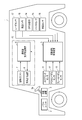
- FIG. 1 is a diagram showing an overall configuration of an automatic driving control system including a driver awakening support device as an embodiment of a driver body condition recovery support device of the present invention.
- FIG. 2 is a block diagram illustrating a functional configuration of the driver awakening support device illustrated in FIG. 1.
- FIG. 3 is a flowchart showing a procedure and details of support for driver awakening by the driver awakening support device shown in FIG.
- FIG. 4 is a diagram schematically showing an assumed social background in one embodiment of the present invention.
- FIG. 5 is a diagram schematically showing another assumed social background in the embodiment of the present invention.
- FIG. 1 is a diagram showing an overall configuration of an automatic driving control system including a driver awakening support device as an embodiment of a driver body condition recovery support device of the present invention.
- This automatic driving control system is mounted on a vehicle 1 such as a passenger car.
- the vehicle 1 includes, as basic equipment, a power unit 2 including a power source and a transmission, and a steering device 3 equipped with a steering wheel 3a.
- a power unit 2 including a power source and a transmission
- a steering device 3 equipped with a steering wheel 3a.
- An engine and / or a motor is used as the power source.
- the vehicle 1 is configured to be able to travel in either the manual operation mode or the automatic operation mode.
- the manual driving mode is a mode in which the vehicle 1 is driven mainly by a driver's manual driving operation, for example.
- the manual operation mode includes, for example, an operation mode for driving the vehicle based only on the driver's driving operation, and an operation mode for performing driving operation support control for supporting the driving operation of the driver while mainly driving the driver's driving operation. Is included.
- the driving operation support control assists the steering torque so that the driver's steering becomes an appropriate steering amount based on the curvature of the curve when the vehicle 1 is traveling on the curve, for example.
- the driving operation support control includes control for assisting a driver's accelerator operation (for example, operation of an accelerator pedal) or brake operation (for example, operation of a brake pedal), manual steering (manual operation of steering), and manual speed adjustment (speed). Adjustment manual operation) is also included.
- a driver's accelerator operation for example, operation of an accelerator pedal
- brake operation for example, operation of a brake pedal
- manual steering manual operation of steering
- speed manual speed adjustment
- Adjustment manual operation is also included.
- manual steering the vehicle 1 is steered mainly by the driver's operation of the steering wheel 3a.
- the manual speed adjustment the speed of the vehicle is adjusted mainly by the driver's accelerator operation or brake operation.
- the driving operation support control does not include control for forcibly intervening in the driving operation of the driver and automatically driving the vehicle.
- the driving operation of the driver is reflected in the driving of the vehicle within a preset allowable range, but forcibly intervenes in the driving of the vehicle under certain conditions (for example, deviation from the lane of the vehicle). Control to do is not included.
- the automatic operation mode is a mode that realizes an operation state in which the vehicle automatically travels along the road on which the vehicle travels, for example.
- the automatic driving mode includes, for example, a driving state in which the vehicle automatically travels toward a preset destination without driving by the driver.
- the automatic driving mode it is not always necessary to automatically control all of the vehicle, and the driving state in which the driving operation of the driver is reflected in the driving of the vehicle within the preset allowable range is also included in the automatic driving mode. That is, the automatic driving mode includes control for forcibly intervening in driving of the vehicle under certain conditions, while reflecting the driving operation of the driver in driving of the vehicle within a preset allowable range.
- the vehicle 1 is also provided with an automatic driving control device 5 for executing driving control in the automatic driving mode.
- the automatic driving control device 5 acquires sensing data from a steering sensor 11, an accelerator pedal sensor 12, a brake pedal sensor 13, a GPS (Global Positioning System) receiver 14, a gyro sensor 15, and a vehicle speed sensor 16, respectively.
- the automatic driving control device 5 is a peripheral monitoring system that monitors these sensing data, route information generated by a navigation system (not shown), traffic information acquired by road-to-vehicle communication, and the positions and movements of surrounding people and vehicles.
- the vehicle 1 is automatically controlled based on the information obtained by the above.
- the surrounding monitoring system for example, measures a distance from a surrounding vehicle and outputs distance information to the automatic driving control device 5, and images the surroundings of the vehicle and outputs a video signal thereof to the automatic driving control device 5.
- a peripheral camera 18 for a distance from a surrounding vehicle and outputs distance information to the automatic driving control device 5 and images the surroundings of the vehicle and outputs a video signal
- Automatic control includes, for example, automatic steering (automatic steering operation) and automatic speed adjustment (automatic driving of speed).
- Automatic steering is an operating state in which the steering device 3 is automatically controlled.
- Automatic steering includes LKA (Lane Keeping Assist).
- LKA Li Keeping Assist
- the LKA automatically controls the steering device 3 so that the vehicle 1 does not deviate from the traveling lane even when the driver does not perform the steering operation.
- the driver's steering operation may be reflected in the steering of the vehicle in a range where the vehicle 1 does not deviate from the travel lane (allowable range).
- automatic steering is not limited to LKA.
- Automatic speed adjustment is an operating state in which the speed of the vehicle 1 is automatically controlled.
- Automatic speed adjustment includes ACC (Adaptive Cruise Control). For example, when there is no preceding vehicle ahead of the vehicle 1, ACC performs constant speed control that causes the vehicle 1 to travel at a constant speed at a preset speed, and when the preceding vehicle exists ahead of the vehicle 1. Is a follow-up control that adjusts the vehicle speed of the vehicle 1 in accordance with the inter-vehicle distance from the preceding vehicle.
- the automatic operation control device 5 decelerates the vehicle 1 according to the driver's brake operation (for example, operation of the brake pedal) even when ACC is being executed.
- the automatic operation control device 5 can perform the driver's accelerator operation (for example, accelerator) up to a preset maximum allowable speed (for example, the maximum speed legally determined on the traveling road) even during execution of ACC.
- the vehicle can be accelerated according to the pedal operation.
- the automatic speed adjustment is not limited to ACC but also includes CC (Cruise Control).
- the automatic operation control system of the present embodiment has a driver monitoring system 10 that monitors the driver.
- the driver monitoring system 10 includes a driver awakening support device 6 that promotes a driver's awakening, a driver camera 7 as a driver state detection sensor that detects a driver's state, and an awakening from the driver awakening support device 6.
- a guidance output device 8 for outputting guidance information for assistance.
- the driver camera 7 is installed at a position in front of the driver, such as on the dashboard, for example, and images the driver and outputs the video signal to the driver awakening support device 6.
- the guidance output device 8 has, for example, a speaker and a display, and outputs a voice signal of guidance information output from the driver awakening support device 6 from the speaker and also displays a display signal of guidance information on the display.
- the guidance output device 8 may be configured by one of a speaker and a display.
- the guidance output device 8 may be configured using an image display function or a voice output function of the navigation system.
- FIG. 2 is a block diagram showing the functional configuration.
- the driver awakening support device 6 includes a control unit 61, an input / output interface unit 62, and a storage unit 63.
- the input / output interface unit 62 receives the video signal output from the driver camera 7, converts it into digital data, and inputs the digital data to the control unit 61.
- the input / output interface unit 62 also receives the operation mode information and the stability information output from the automatic operation control device 5 and inputs them to the control unit 61.
- the input / output interface unit 62 further converts the guidance information output from the control unit 61 into a voice signal and a display signal, and outputs them to the guidance output device 8.
- the storage unit 63 uses, as a storage medium, a non-volatile memory that can be written and read at any time, such as an SSD (Solid State Drive) or an HDD (Hard Disk Drive).
- the storage unit 63 includes a driver monitoring video storage unit 631 that stores a driver's monitoring video and a driver state storage unit 632 that stores a driver's status as storage areas used to implement the present embodiment. And a guide information storage unit 633 storing guide information.
- the control unit 61 has a CPU (Central Processing Unit) and a program memory constituting the computer.
- the control unit 61 includes an automatic driving determination unit 611, a driver monitoring video acquisition unit 612, a driver state determination unit 613, a stability determination unit 614, as control functions necessary for carrying out this embodiment.
- a guidance output unit 615 can be realized by causing the CPU to execute a program stored in the program memory.
- the automatic driving determination unit 611 determines whether the vehicle 1 is currently traveling in the manual driving mode or the automatic driving mode based on the driving mode information output from the automatic driving control device 5. have.
- the control unit 61 performs the present embodiment by using the driver monitoring image acquisition unit 612, the driver state determination unit 613, the stability determination unit 614, and the guidance output unit 615. To work.
- the driver monitoring video acquisition unit 612 has a function of acquiring a driver monitoring video from the driver camera 7.
- the driver monitoring video acquisition unit 612 takes in the digital data (driver monitoring video data) of the video signal of the driver output from the driver camera 7 from the input / output interface unit 62, and uses the captured driver monitoring video data.
- the information is stored in the driver monitoring video storage unit 631 of the storage unit 63.
- the driver state determination unit 613 has a function of determining the state of the driver.
- the driver state determination unit 613 reads the driver monitoring video data from the driver monitoring video storage unit 631 at a preset time interval. Next, every time the driver monitoring video data is read, the driver status determination unit 613 performs a process of determining the driver status based on the driver monitoring video data.
- the driver state determination unit 613 stores the determination result in the driver state storage unit 632.
- the stability determination unit 614 has a function of determining whether the stability of the current automatic driving is high based on the stability information output from the automatic driving control device 5.
- the guidance output unit 615 has a function of reading the guidance information stored in advance from the guidance information storage unit 633 and outputting the guidance information to the guidance output device 8. Which guidance information the guidance output unit 615 reads and outputs from the guidance information storage unit 633 depends on the determination result of the driver state determination unit 613 stored in the driver state storage unit 632 and the stability determination unit. This is determined according to the determination result at 614.
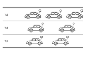
- the driving environment assumed in this embodiment is, for example, as follows.
- FIG. 4 schematically shows such an operating environment.
- a vehicle C1 represents a vehicle traveling in the manual operation mode
- a vehicle C2 represents a vehicle traveling in the automatic operation mode.
- the vehicle C1 is referred to as a manually driven vehicle C1
- the vehicle C2 is referred to as an automatically driven vehicle C2.
- the lane TL1 represents a so-called traveling lane, and is located on the side where the service area, the parking area, and the interchange side road are located.
- Lane TL2 represents a so-called overtaking lane.
- the lane TL3 represents an automatic driving permission lane in which traveling in the automatic driving mode is permitted.
- the autonomous driving vehicle C2 exists only in the lane TL3.
- the driver In this driving environment, the driver is allowed to concentrate on something other than driving to some extent while driving in the automatic driving mode. However, when the destination is approaching, that is, when the interchange to get off is approaching, the driver needs to finish traveling in the automatic operation mode and switch to traveling in the manual operation mode.
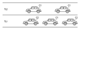
- FIG. 5 schematically shows such an operating environment.
- the lane TL1 represents a so-called traveling lane, and is located on the side where the service area, the parking area, and the interchange side road are located.
- Lane TL2 represents a so-called overtaking lane.
- a manual driving vehicle C1 and an automatic driving vehicle C2 are mixed.
- the driver In this driving environment, the driver is allowed to concentrate to something other than driving to some extent while driving in the automatic driving mode. However, when the destination is approaching, that is, when the interchange to get off is approaching, the driver needs to finish traveling in the automatic operation mode and switch to traveling in the manual operation mode.
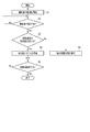
- FIG. 3 is a flowchart showing the procedure and details of driver awakening support.
- This flowchart is based on the fact that the automatic driving determination unit 611 of the driver awakening support device 6 determines that the automatic driving control device 5 has started automatic driving based on the driving mode information from the automatic driving control device 5. Start.
- driver monitoring system 10 starts monitoring the driver in step S1.
- Driver monitoring continues, for example, during automatic driving.
- the driver is monitored as follows, for example.
- the driver camera 7 When the automatic driving is started, the driver camera 7 is activated, and continuously captures a predetermined range including the driver's face and outputs the video signal.
- the driver awakening support device 6 receives digital data (driver monitoring video data) of the video signal output from the driver camera 7 from the input / output interface unit 62 under the control of the driver monitoring video acquisition unit 612.
- the captured driver monitoring video data is stored in the driver monitoring video storage unit 631 of the storage unit 63.
- the driver's imaging may be performed intermittently at predetermined time intervals.
- the driver camera 7 or the input / output interface unit 62 may encode the video signal according to a predetermined encoding method. In this way, it is possible to reduce the information amount of the monitoring video data and save the storage capacity of the driver monitoring video storage unit 631.
- the driver awakening support device 6 next passes a certain time under the control of the driver state determination unit 613 in step S2. Each time is determined, the state of the driver is determined.
- the time interval for determining the driver's state may be set to a short interval such as about 1 second so that a substantially continuous determination can be performed, or set to a relatively long interval such as 10 to 30 seconds. It may be.
- the determination of the driver's state is performed as follows, for example.
- the driver state determination unit 613 reads the driver monitoring video data from the driver monitoring video storage unit 631 and determines the state of the driver based on the driver monitoring video data.
- the driver state determination unit 613 stores information indicating the determination result in the driver state storage unit 632 in association with information indicating the determination timing, for example, time stamp information.
- the state of the driver determined by the driver state determination unit 613 is whether or not the body condition is lowered. Specifically, in this embodiment, whether or not the driver is drowsy.
- the determination of the driver's state is performed as follows, for example.
- the driver state determination unit 613 recognizes the driver's arousal level by detecting the open state of the driver's eyes, the blinking frequency, the eye movement, and the like based on the driver monitoring video data. Next, the driver state determination unit 613 compares the driver's arousal level with a preset arousal level threshold value to determine whether or not the driver's physical condition is reduced, that is, the driver is drowsy. Determine whether or not.
- the preset arousal level threshold is determined by deep learning of driver monitoring video data for a large number of subjects, or established academically, and the driver is drowsy. It may be set to the degree of awakening.
- step S3 Determination of Stability
- the driver awakening support device 6 is determined in step S3. Determines whether the stability is high under the control of the stability determination unit 614. The determination of the stability is performed as follows, for example.
- the stability determination unit 614 of the driver awakening support device 6 determines the stability of automatic driving indicated by the stability information received from the automatic driving control device 5 via the input / output interface unit 62 as a preset stability threshold value. To determine whether or not the stability of the automatic driving is high.
- the automatic operation control device 5 determines whether or not to continue the automatic operation as disclosed in, for example, Japanese Patent Application Laid-Open No. 2015-032291.
- the control limit which is a condition in which support is restricted by a limit on control performance
- the recognition limit which is a condition in which support is restricted by a limit on recognition performance
- the condition in which support is restricted by a limit on processing performance is determined based on the three kinds of conditions of the processing limit.
- the control limit for example, automatic driving is continued when another vehicle has not suddenly interrupted in front of the vehicle during follow-up traveling, or when sufficient deceleration can be achieved despite sudden deceleration of the preceding vehicle.
- the recognition limit for example, when the wiper is not operated at high speed, or when the dirt of the peripheral camera 18 is not detected, the surrounding environment acquired by the peripheral camera 18 is good, for example, no fog is generated.
- the reliability of the radar sensor 17 is high, the automatic operation is continued.
- the processing limit for example, when it is not in a state where the original automatic travel support cannot be performed due to abnormality of various sensors or CPU, the automatic operation is continued with high reliability.
- the automatic operation control device 5 determines whether or not the respective conditions are satisfied by comparing the measured values for each of the three types of conditions used for the continuation determination of the automatic operation with the respective threshold values.
- the automatic driving control device 5 outputs those measured values to the driver awakening support device 6 as stability information indicating the stability.
- the automatic operation control device 5 may output these measurement values as stability information as they are, but adds them together, averages them, or takes a weighted average weighted for each condition. Etc. Further, for example, only one condition such as a measurement value for the recognition limit may be output as the stability information.
- the stability determination unit 614 of the driver awakening support device 6 compares the stability information input from the automatic driving control device 5 with preset stability threshold information, thereby increasing the stability of automatic driving. It is determined whether or not.
- the preset stability threshold is obtained by deep learning of stability data for a large number of driving situations, or has been established academically, and can be determined to be stable automatic driving. May be set in degrees.
- the driver awakening support device 6 controls the body under the control of the guidance output unit 615 in step S4.
- Guidance information suggesting that the user is moving is transmitted to the guidance output device 8. In this case, it suggests a movement that moves the whole body, which can improve the arousal level, rather than a local movement such as a leg tip. More specifically, it suggests that the driver performs body stretching exercises.
- guidance information that suggests that the driver performs body stretching exercises is stored in advance in the guidance information storage unit 633, and the guidance output unit 615 reads out the guidance information from the guidance information storage unit 633 and outputs it. To do.
- the guidance information that suggests that the driver performs body stretching exercises may be content such as “please perform body stretching exercises”, for example.
- the guidance information that suggests that the driver is to stretch the body is converted into an audio signal and / or a display signal in the input / output interface unit 62 and output to the guidance output device 8.
- the guidance output device 8 outputs a voice signal from a speaker as a voice message, for example.
- the guidance output device 8 may display the display signal on the display device as a display message.
- the driver awakening support device 6 determines that the driver is not stretched under the control of the guidance output unit 615 in step S5.
- Guide information other than the guide information suggesting that exercise is performed is transmitted to the guide output device 8.
- this guidance information is stored in advance in the guidance information storage unit 633, and the guidance output unit 615 reads out the guidance information indicating the warning message from the guidance information storage unit 633 and outputs it.
- the guidance information indicating the warning message may be, for example, contents such as “It seems to be drowsy. Be careful.” Or “Please do not sleep.”
- the guidance information indicating the warning message is converted into an audio signal and / or a display signal in the input / output interface unit 62 and output to the guidance output device 8.
- the guidance output device 8 outputs a voice signal from a speaker as a voice message, for example.
- the guidance output device 8 may display the display signal on the display device as a display message.
- a message may be a warning sound or music, and is not limited to a sound.
- it may be a vibration of a driver's seat or a vibrator provided on the steering wheel 3a.
- the driver utters the predetermined voice, that is, Active stimulation may be applied.
- guidance information for performing an exercise of moving only the tip of the leg for example, which can be performed without removing the hand from the steering wheel may be output.
- step S2 determines that the driver is not drowsy in step S2, and after outputting the guidance information in step S4 or step S5, step In S6, it is determined whether or not the automatic operation is finished. This is because the automatic driving determination unit 611 of the driver awakening support device 6 determines whether or not the automatic driving control device 5 finishes the automatic driving and returns to the manual driving based on the driving mode information from the automatic driving control device 5. Judgment by
- step S2 If it is determined that the automatic operation has not ended, the process returns to step S2. If it is determined that the automatic operation has ended, the process ends.
- the driver state determination unit 613 determines whether or not the driver's body condition is lowered by the driver state determination unit 613 during the automatic driving in the automatic driving mode. Determine whether it is hosting. Then, when it is determined that the driver is drowsy, the driver awakening support that suggests an active stimulus, in particular, suggests that the body stretches, is performed. That is, during automatic driving, the driver does not need to perform a driving operation of the vehicle, and thus can perform various exercises using the whole body, such as body stretching exercises. Therefore, it is suggested that when the driver is drowsy during automatic driving, he / she performs body stretching exercises. This makes it possible for the driver to execute such body stretching exercise, and the driver's arousal level can be further increased.
- the body stretching movement is a posture in which the hand is away from the steering wheel and the foot is away from the accelerator pedal or the brake pedal, so it may not always be performed during automatic driving. Therefore, according to one embodiment of the present invention, switching between the suggestion of such body stretching movement and the other awakening support is output according to the stability of automatic driving. That is, it suggests that the body stretches only when the stability of automatic driving is high. In other words, it is judged by the stability of automatic driving whether or not it is safe to get away from the steering wheel, feet from the accelerator pedal or brake pedal, and only when it is safe Suggest to do such exercise.
- the awakening support can be performed while ensuring safety.
- the driver state detection sensor is configured by the driver camera 7 and the driver state is determined based on an image signal including the driver's face obtained by the driver camera 7 will be described as an example. did.
- the driver state detection sensor is not limited to the driver camera 7, and is configured by a biological sensor that acquires biological information of the driver, and based on a biological signal obtained by the biological sensor, for example, by a pulse wave sensor or a heart rate sensor.
- the state of the driver may be determined based on the detected pulse wave signal or heartbeat signal of the driver or a signal representing the vertical movement of the diaphragm detected by the pressure sensor.
- the driver when the driver is drowsiness other than during automatic driving, that is, during manual driving, the driver may be awakened by the output of a passive stimulus when the driver is drowsy.
- the driver when the driver is drowsiness other than during automatic driving, that is, during manual driving, the driver may be awakened by the output of a passive stimulus when the driver is drowsy.
- the driver state detection sensor is configured with a sensor biosensor, so that the driver affects the driving operation other than sleepiness, such as the driver's fatigue and the degree of stiffness of the shoulder and neck. It is possible to detect a decrease in body condition. Therefore, as the driver state determined by the driver state determination unit 613, it may be determined whether or not the driver is drowsy and whether or not the shoulder or neck is stuck. As a result, the guidance output unit 615 releases the hand from the steering wheel only when the stability of the automatic driving is high when the driver's shoulder or neck is stuck during automatic driving in the automatic driving mode. It is possible to provide support for relieving stiff shoulders and necks by suggesting exercises that turn the shoulders and turn the head that shakes the line of sight from the direction of travel. That is, the driver body condition recovery support device may be a driver stiffness elimination support device.
- the present invention can provide a driver body condition recovery support device that can support recovery without deteriorating safety against various driver body condition drops.
- the vehicle type, the function of the automatic driving control device, the driver physical condition recovery support procedure and the support content of the driver physical condition recovery support device, etc. are variously modified and implemented without departing from the gist of the present invention. Is possible.
- the present invention is not limited to the above-described embodiment as it is, and can be embodied by modifying the constituent elements without departing from the scope of the invention in the implementation stage.
- various inventions can be formed by appropriately combining a plurality of constituent elements disclosed in the embodiment. For example, some components may be deleted from all the components shown in the embodiment. Furthermore, you may combine suitably the component covering different embodiment.
- a driver physical condition recovery support device which is mounted on a vehicle having an automatic driving control device and supports recovery of a lowered physical condition of the driver when the vehicle is in an automatic driving mode, comprising a hardware processor and a memory And The hardware processor is During the automatic driving of the vehicle, the sensing result of a driver state detection sensor that detects the state of the driver of the vehicle is stored in the memory, and based on the sensing result, the body condition of the driver is determined, A driver that changes a stimulus given to the driver based on a stability of automatic driving by the automatic driving control device when it is determined that the physical condition of the driver is lower than a preset physical condition threshold value; Body condition recovery support device.
- a driver physical condition recovery support method that is mounted on a vehicle having an automatic driving control device and that is executed by an apparatus for supporting recovery of a reduced physical condition of the driver during the automatic driving mode of the vehicle, Using a hardware processor, during the automatic driving of the vehicle, a sensing result of a driver state detection sensor that detects the state of the driver of the vehicle is stored in a memory, and based on the sensing result, the body of the driver Judge the condition, When it is determined that the driver's physical condition is lower than a preset physical condition threshold using the hardware processor, the driver is determined based on the stability of automatic driving by the automatic driving control device.
- a driver's physical condition recovery support method that changes the stimulus given.
Landscapes
- Physics & Mathematics (AREA)
- General Physics & Mathematics (AREA)
- Engineering & Computer Science (AREA)
- Business, Economics & Management (AREA)
- Emergency Management (AREA)
- Automation & Control Theory (AREA)
- Mathematical Physics (AREA)
- Transportation (AREA)
- Mechanical Engineering (AREA)
- Traffic Control Systems (AREA)
- Emergency Alarm Devices (AREA)
- Control Of Driving Devices And Active Controlling Of Vehicle (AREA)
Abstract
運転者覚醒支援装置は、自動運転制御装置による自動運転の安定度を判定する安定度判定部と、車両の運転者の状態を検出する運転者状態検出センサのセンシング結果に基づいて運転者の身体コンディションを判定する身体コンディション判定部と、身体コンディション判定部により運転者の身体コンディションが予め設定された身体コンディション閾値よりも低下したと判定されたとき、身体コンディション回復支援を運転者に対して行う身体コンディション回復支援部と、を備えている。身体コンディション回復支援部は、身体コンディション回復支援として運転者に与える刺激を、安定度判定部によって判定された自動運転の安定度に基づいて変更する。
Description
この発明は、車両の自動運転モード時において低下している運転者の身体コンディションの回復を支援するための運転者身体コンディション回復支援装置、方法およびプログラムに関する。
運転者は、運転操作のために同じ姿勢を長時間続けなければならず、疲労が蓄積し、これが肩こりや首のこりの原因となっている。そこで、近年では、車両の運転操作を自動的に制御する自動運転制御装置を搭載した車両が提案されている。
車両の運転者は、車両を運転している間、十分に覚醒していることが求められる。しかし一方で、このような自動運転中は、運転者が運転操作を行っていないため、運転者が眠くなり易い。車両の運転者は、車両を運転している間、十分に覚醒していることが求められており、これは、自動運転中であっても同様である。現状においては、運転操作を完全に自動運転制御装置に任せられるものではなく、緊急事態に咄嗟に対応できることが必要であるからである。
このような事情から、自動運転中に、運転者の眠気を覚まさせる装置、言い換えれば、運転者の覚醒を促す装置が提案されている。例えば、日本国特開2015-032291号公報は、自動運転中に、自動運転の継続が可能か否かの判定を行うことに加えて、運転者が居眠り等をしていない正常に運転できる状態であるか否かの判定を行い、正常に運転できる状態に無ければ、自動運転の継続が可能であっても運転者への警告を行う装置を開示している。
前記日本国特開2015-032291号公報は、具体的に警告をどのようにして行うかは開示していない。一般的には、音、振動、光、香り等の受動的な刺激を運転者に与えることが想定される。
現在、運転者の眠気を検出する手法や技術、運転者に与える刺激、刺激の与え方などにおいて、開発が進められている。しかし、刺激によって運転者の覚醒度の向上度合は異なる。また、自動運転モードが突如何等かの理由により手動運転モードに切り替えられる可能性が高い場合には、運転者に与える刺激は手動運転に復帰できる刺激であることが好ましい。
さらに、運転者の運転操作に影響を及ぼす運転者身体コンディションの低下としては、眠気だけでなく、疲労蓄積による肩こりや首のこりなどもある。この肩や首のこりなどの運転者身体コンディション低下についても、運転者に対して何等かの刺激を与えることで、回復を図れると期待される。
しかし、この場合も、前述の眠気の場合と同様、刺激によって運転者身体コンディションの回復度合は異なる。また、自動運転モードが手動運転モードに切り替えられる可能性が高い場合には、運転者に与える刺激は手動運転に復帰できる刺激であることが好ましいことも同様である。
この発明は、安全を損なうこと無く、運転者の低下した身体コンディションの回復を支援することができる運転者身体コンディション回復支援装置、方法およびプログラムを提供しようとするものである。
上記課題を解決するため、この発明の第1の態様は、自動運転制御装置を有する車両に装着され、前記車両の自動運転モード時における運転者の低下した身体コンディションの回復を支援するための運転者身体コンディション回復支援装置であって、前記自動運転制御装置による自動運転の安定度を判定する安定度判定部と、前記車両の運転者の状態を検出する運転者状態検出センサのセンシング結果に基づいて、前記運転者の身体コンディションを判定する身体コンディション判定部と、前記身体コンディション判定部により前記運転者の身体コンディションが予め設定された身体コンディション閾値よりも低下したと判定されたとき、身体コンディション回復支援を運転者に対して行う身体コンディション回復支援部と、を備えている。身体コンディション回復支援部は、身体コンディション回復支援として運転者に与える刺激を、安定度判定部によって判定された自動運転の安定度に基づいて変更する。
この発明の第2の態様に係る運転者身体コンディション回復支援装置は、第1の態様に係る運転者身体コンディション回復支援装置において、前記身体コンディション回復支援部は、前記身体コンディション判定部により前記運転者の身体コンディションが前記予め設定された身体コンディション閾値よりも低下したと判定されたとき、前記安定度判定部によって判定された前記安定度が予め設定された安定度閾値以上であれば、前記運転者が体の伸び運動を行うことを示唆する案内情報を出力する。
この発明の第3の態様に係る運転者身体コンディション回復支援装置は、第1の態様に係る運転者身体コンディション回復支援装置において、前記身体コンディション回復支援部は、前記自動運転の安定度が前記予め設定された安定度閾値よりも低いときには、前記運転者が体の伸び運動を行うこと示唆する案内情報以外の案内情報を出力する。
この発明の第4の態様に係る運転者身体コンディション回復支援装置は、第1乃至第3の態様のいずれか一つに係る運転者身体コンディション回復支援装置において、前記予め設定された安定度閾値は、前記自動運転制御装置における、制御性能上の限界により支援が制約される条件である制御限界、認識性能上の限界により支援が制約される条件である認識限界、及び、処理性能上の限界により支援が制約される条件である処理限界、のそれぞれに基づいて決定された、前記自動運転が安定していると判定し得る安定度に設定されている。
この発明の第5の態様は、自動運転制御装置を有する車両に装着され、前記車両の自動運転モード時における運転者の低下した身体コンディションの回復支援するための装置が実行する運転者身体コンディション回復支援方法であって、前記自動運転制御装置による自動運転の安定度を判定する安定度判定ステップと、前記車両の運転者の状態を検出する運転者状態検出センサのセンシング結果に基づいて、前記運転者の身体コンディションを判定する身体コンディション判定ステップと、前記身体コンディション判定ステップにおいて前記運転者の身体コンディションが予め設定された身体コンディション閾値よりも低下したと判定されたとき、前記安定度判定ステップにおいて判定された前記自動運転の安定度に基づいて、前記運転者に与える刺激を変更する身体コンディション回復支援ステップと、を備えている。
この発明の第6の態様は、第1乃至第4の態様に係る運転者身体コンディション回復支援装置が備える各部の機能をコンピュータに実行させるプログラムである。
以下、図面を参照してこの発明に係わる実施形態を説明する。
[一実施形態]
(構成)
図1は、この発明の運転者身体コンディション回復支援装置の一実施形態としての運転者覚醒支援装置を備えた自動運転制御システムの全体構成を示す図である。この自動運転制御システムは、乗用車等の車両1に搭載される。
[一実施形態]
(構成)
図1は、この発明の運転者身体コンディション回復支援装置の一実施形態としての運転者覚醒支援装置を備えた自動運転制御システムの全体構成を示す図である。この自動運転制御システムは、乗用車等の車両1に搭載される。
車両1は、基本設備として、動力源および変速装置を含むパワーユニット2と、ステアリングホイール3aが装備された操舵装置3とを備えている。動力源としては、エンジンまたはモータ、あるいはその両方が用いられる。
車両1は、手動運転モードまたは自動運転モードのいずれかの運転モードで走行可能に構成されている。
手動運転モードは、例えば、運転者の手動による運転操作を主体として車両1を走行させるモードである。手動運転モードには、例えば、運転者の運転操作のみに基づいて車両を走行させる動作モードと、運転者の運転操作を主体としながら運転者の運転操作を支援する運転操作支援制御を行う動作モードが含まれる。
運転操作支援制御は、例えば、車両1のカーブ走行時にカーブの曲率に基づいて運転者の操舵が適切な操舵量となるように操舵トルクをアシストする。また運転操作支援制御には、運転者のアクセル操作(例えばアクセルペダルの操作)またはブレーキ操作(例えばブレーキペダルの操作)を支援する制御と、手動操舵(操舵の手動運転)および手動速度調整(速度調整の手動運転)も含まれる。手動操舵は、運転者のステアリングホイール3aの操作を主体として車両1の操舵を行う。手動速度調整は、運転者のアクセル操作又はブレーキ操作を主体として車両の速度調整を行う。
なお、運転操作支援制御には、運転者の運転操作に強制的に介入して、車両を自動走行させる制御は含まれない。すなわち、手動運転モードには、予め設定された許容範囲において運転者の運転操作を車両の走行に反映させるが、一定条件(例えば車両の車線逸脱等)の下で車両の走行に強制的に介入する制御は含まれない。
一方、自動運転モードは、例えば、車両の走行する道路に沿って自動で車両を走行させる運転状態を実現するモードである。自動運転モードには、例えば、運転者が運転操作をすることなく、予め設定された目的地に向かって自動的に車両を走行させる運転状態が含まれる。自動運転モードは、必ずしも車両の全ての制御を自動で行う必要はなく、予め設定された許容範囲において運転者の運転操作を車両の走行に反映する運転状態も自動運転モードに含まれる。すなわち、自動運転モードには、予め設定された許容範囲において運転者の運転操作を車両の走行に反映させるが、一定条件の下で車両の走行に強制的に介入する制御が含まれる。
図1において、車両1はまた、自動運転モードによる運転制御を実行するための自動運転制御装置5を備えている。自動運転制御装置5は、ステアリングセンサ11、アクセルペダルセンサ12、ブレーキペダルセンサ13、GPS(Global Positioning System)受信機14、ジャイロセンサ15、および車速センサ16からそれぞれセンシングデータを取得する。自動運転制御装置5は、これらのセンシングデータと、図示しないナビゲーションシステムで生成される経路情報や、路車間通信により取得される交通情報、周辺の人や車両の位置と動きを監視する周辺モニタリングシステムにより得られる情報をもとに、車両1の走行を自動制御する。周辺モニタリングシステムは、例えば、周辺の車両との距離を測定して距離情報を自動運転制御装置5へ出力するレーダセンサ17と、車両周辺を撮像してその映像信号を自動運転制御装置5へ出力する周辺カメラ18と、を備えている。
自動制御には、例えば、自動操舵(操舵の自動運転)と自動速度調整(速度の自動運転)がある。自動操舵は、操舵装置3を自動で制御する運転状態である。自動操舵にはLKA(Lane Keeping Assist)が含まれる。LKAは、例えば、運転者がステアリング操作をしない場合であっても、車両1が走行車線から逸脱しないように自動で操舵装置3を制御する。なお、LKAの実行中であっても、車両1が走行車線を逸脱しない範囲(許容範囲)において運転者のステアリング操作を車両の操舵に反映してもよい。なお、自動操舵はLKAに限らない。
自動速度調整は、車両1の速度を自動で制御する運転状態である。自動速度調整にはACC(Adaptive Cruise Control)が含まれる。ACCとは、例えば、車両1の前方に先行車が存在しない場合は予め設定された設定速度で車両1を定速走行させる定速制御を行い、車両1の前方に先行車が存在する場合には先行車との車間距離に応じて車両1の車速を調整する追従制御を行うものである。自動運転制御装置5は、ACCを実行中であっても、運転者のブレーキ操作(例えばブレーキペダルの操作)に応じて車両1を減速させる。また自動運転制御装置5は、ACCを実行中であっても、予め設定された最大許容速度(例えば走行中の道路において法的に定められた最高速度)まで、運転者のアクセル操作(例えばアクセルペダルの操作)に応じて車両を加速させることもできる。なお、自動速度調整は、ACCに限らず、CC(Cruise Control:定速制御)等も含まれる。
本実施形態の自動運転制御システムは、運転者を監視する運転者監視システム10を有している。運転者監視システム10は、運転者の覚醒を促す運転者覚醒支援装置6と、運転者の状態を検出する運転者状態検出センサとしての運転者カメラ7と、運転者覚醒支援装置6からの覚醒支援の案内情報を出力する案内出力装置8と、を備えている。
運転者カメラ7は、例えばダッシュボード上のような運転者の正面となる位置に設置され、運転者を撮像してその映像信号を運転者覚醒支援装置6へ出力する。
案内出力装置8は、例えば、スピーカと表示器を有し、運転者覚醒支援装置6から出力された案内情報の音声信号をスピーカから出力すると共に、案内情報の表示信号を表示器に表示する。案内出力装置8は、スピーカと表示器の一方で構成されてもよい。案内出力装置8は、ナビゲーションシステムの画像表示機能や音声出力機能を利用して構成されてもよい。
運転者覚醒支援装置6は、自動運転制御装置5が自動運転モードによる運転制御を行っている際、運転者の覚醒度が低くなったときに、運転者の覚醒を促すもので、以下のように構成される。図2はその機能構成を示すブロック図である。
運転者覚醒支援装置6は、制御ユニット61と、入出力インタフェースユニット62と、記憶ユニット63と、を備えている。
入出力インタフェースユニット62は、運転者カメラ7から出力された映像信号を受信してデジタルデータに変換して、制御ユニット61に入力する。入出力インタフェースユニット62はまた、自動運転制御装置5から出力された運転モード情報および安定度情報を受信して、それらを制御ユニット61に入力する。入出力インタフェースユニット62はさらに、制御ユニット61から出力された案内情報を音声信号および表示信号に変換して案内出力装置8へ出力する。
記憶ユニット63は、記憶媒体として、例えばSSD(Solid State Drive)やHDD(Hard Disk Drive)等の随時書き込みおよび読み出しが可能な不揮発性メモリを使用したものである。記憶ユニット63は、本実施形態を実施するために使用する記憶領域として、運転者の監視映像を記憶する運転者監視映像記憶部631と、運転者の状態を記憶する運転者状態記憶部632と、案内情報を記憶している案内情報記憶部633と、を備えている。
制御ユニット61は、コンピュータを構成するCPU(Central Processing Unit)およびプログラムメモリを有している。制御ユニット61は、本実施形態を実施するために必要な制御機能として、自動運転判定部611と、運転者監視映像取得部612と、運転者状態判定部613と、安定度判定部614と、案内出力部615と、を備えている。なお、これらの制御機能はいずれもプログラムメモリに格納されたプログラムをCPUに実行させることにより実現されることができる。
自動運転判定部611は、自動運転制御装置5から出力された運転モード情報により、車両1が現在、手動運転モードで走行しているのか、または自動運転モードで走行しているのかを判定する機能を有している。自動運転モードで走行している場合、制御ユニット61は、本実施形態を実施するために、運転者監視映像取得部612、運転者状態判定部613、安定度判定部614、および案内出力部615を機能させる。
運転者監視映像取得部612は、運転者カメラ7から運転者の監視映像を取得する機能を有している。運転者監視映像取得部612は、運転者カメラ7から出力された運転者の映像信号のデジタルデータ(運転者監視映像データ)を入出力インタフェースユニット62から取り込み、この取り込んだ運転者監視映像データを記憶ユニット63の運転者監視映像記憶部631に記憶させる。
運転者状態判定部613は、運転者の状態を判定する機能を有している。運転者状態判定部613は、運転者監視映像記憶部631から予め設定された時間間隔で運転者監視映像データを読み込む。次に運転者状態判定部613は、運転者監視映像データを読み込む毎に、運転者監視映像データに基づいて運転者の状態を判定する処理を行う。運転者状態判定部613は、判定結果を、運転者状態記憶部632に記憶させる。
安定度判定部614は、自動運転制御装置5から出力された安定度情報により、現在の自動運転の安定度が高いか否かを判定する機能を有している。
案内出力部615は、案内情報記憶部633から予め記憶されている案内情報を読み込み、案内出力装置8へ出力する機能を有している。案内出力部615が、案内情報記憶部633からいずれの案内情報を読み出して出力するかは、運転者状態記憶部632に記憶されている運転者状態判定部613の判定結果と、安定度判定部614での判定結果とに応じて決定する。
(想定している運転環境または世界)
次に、以上のように構成された運転者覚醒支援装置の動作の説明に先立ち、この実施形態において、想定している運転環境について説明する。この実施形態において、想定している運転環境は、例えば、次のようなものである。
次に、以上のように構成された運転者覚醒支援装置の動作の説明に先立ち、この実施形態において、想定している運転環境について説明する。この実施形態において、想定している運転環境は、例えば、次のようなものである。
(1)世界中の随所において自動運転モードによる走行が可能となるわけではなく、高速道路の一部に自動運転専用レーンが設けられ、専用レーンのみで自動運転モードによる走行が可能になる場合を想定する。
図4は、このような運転環境を模式的に示している。図4において、車両C1は、手動運転モードで走行中の車両を表し、車両C2は、自動運転モードで走行中の車両を表している。以下において、便宜上、車両C1を手動運転車C1と称し、車両C2を自動運転車C2と称する。また、車線TL1は、いわゆる走行車線を表しており、サービスエリアやパーキングエリアやインターチェンジの側道が位置する側に位置している。車線TL2は、いわゆる追い越し車線を表している。車線TL3は、自動運転モードによる走行も許される自動運転許可車線を表している。自動運転車C2は、車線TL3においてのみ存在する。
この運転環境において、運転者は、自動運転モードによる走行中は、ある程度、運転以外のことに集中することが許される。しかし、目的地が近くなったときには、すなわち、降りるべきインターチェンジが近づいたときには、運転者は、自動運転モードによる走行を終了して、手動運転モードによる走行に切り替えることが必要とされる。
(2)世界中の随所において自動運転モードによる走行が可能となるわけではなく、高速道路の一部の区間において、手動運転モードで走行中の車両と自動運転モードで走行中の車両が混在するレーンが存在する場合を想定する。
図5は、このような運転環境を模式的に示している。図5において、車両C1と車両C2の意味は図4と同様である。また、車線TL1は、いわゆる走行車線を表しており、サービスエリアやパーキングエリアやインターチェンジの側道が位置する側に位置している。車線TL2は、いわゆる追い越し車線を表している。車線TL1においては、手動運転車C1と自動運転車C2が混在している。
この運転環境においては、運転者は、自動運転モードによる走行中は、ある程度、運転以外のことに集中することが許される。しかし、目的地が近くなったときには、すなわち、降りるべきインターチェンジが近づいたときには、運転者は、自動運転モードによる走行を終了して、手動運転モードによる走行に切り替えることが必要とされる。
(動作)
次に、このような運転環境の想定の下において、前述したように構成された運転者覚醒支援装置6の動作を説明する。図3はその全体の運転者覚醒支援の手順と支援内容を示すフローチャートである。
次に、このような運転環境の想定の下において、前述したように構成された運転者覚醒支援装置6の動作を説明する。図3はその全体の運転者覚醒支援の手順と支援内容を示すフローチャートである。
なお、このフローチャートは、運転者覚醒支援装置6の自動運転判定部611が、自動運転制御装置5からの運転モード情報によって、自動運転制御装置5が自動運転を開始したと判定することに応じて、スタートする。
(1)運転者監視開始
自動運転制御装置5による自動運転が開始されると、運転者監視システム10は、ステップS1により、運転者の監視を開始する。運転者の監視は、例えば、自動運転の間、続けられる。運転者の監視は、例えば、次のようにして行う。
自動運転制御装置5による自動運転が開始されると、運転者監視システム10は、ステップS1により、運転者の監視を開始する。運転者の監視は、例えば、自動運転の間、続けられる。運転者の監視は、例えば、次のようにして行う。
自動運転が開始されると、運転者カメラ7が起動し、運転者の顔を含む所定の範囲を連続的に撮像してその映像信号を出力する。この状態で運転者覚醒支援装置6は、運転者監視映像取得部612の制御の下、運転者カメラ7から出力された映像信号のデジタルデータ(運転者監視映像データ)を入出力インタフェースユニット62から取り込み、この取り込んだ運転者監視映像データを記憶ユニット63の運転者監視映像記憶部631に記憶させる。
なお、運転者の撮像は、所定の時間間隔で間欠的に行ってもよい。また、運転者カメラ7または入出力インタフェースユニット62において、映像信号を所定の符号化方式に応じて符号化するようにしてもよい。このようにすると、監視映像データの情報量を減らして運転者監視映像記憶部631の記憶容量を節約することが可能となる。
(2)運転者状態の判定
運転者監視映像データの取得が開始されると、ステップS2において、運転者覚醒支援装置6は、次に運転者状態判定部613の制御の下、一定時間の経過が判定される毎に、運転者の状態の判定を行う。この運転者の状態判定の時間間隔は、例えば実質的に連続的な判定を行えるような1秒程度の短い間隔に設定してもよく、また10~30秒といった比較的長い間隔に設定するようにしてもよい。運転者の状態の判定は、例えば、次のようにして行われる。
運転者監視映像データの取得が開始されると、ステップS2において、運転者覚醒支援装置6は、次に運転者状態判定部613の制御の下、一定時間の経過が判定される毎に、運転者の状態の判定を行う。この運転者の状態判定の時間間隔は、例えば実質的に連続的な判定を行えるような1秒程度の短い間隔に設定してもよく、また10~30秒といった比較的長い間隔に設定するようにしてもよい。運転者の状態の判定は、例えば、次のようにして行われる。
運転者状態判定部613は、運転者監視映像記憶部631から運転者監視映像データを読み込み、運転者監視映像データに基づいて、運転者の状態を判定する。運転者状態判定部613は、判定結果を表す情報を、判定タイミングを表す情報、例えばタイムスタンプ情報と関連付けて運転者状態記憶部632に記憶させる。
運転者状態判定部613が判定する運転者の状態は、身体コンディションが低下しているか否かであり、具体的には、この実施形態では、運転者が眠気を催しているか否かである。運転者の状態の判定は、例えば、次のようにして行われる。
運転者状態判定部613は、運転者監視映像データに基づいて、運転者の眼の開眼の状態、まばたきの頻度、または眼球運動等を検出することで、運転者の覚醒度を認識する。次に、運転者状態判定部613は、運転者の覚醒度を、予め設定された覚醒度閾値と比較することにより、運転者の身体コンディションが低下しているか否か、すなわち、運転者が眠気を催しているか否かを判定する。ここにおいて、予め設定された覚醒度閾値は、多数の被検体についての運転者監視映像データのディープラーニングによって求められた、あるいは、学術的に確立された、運転者が眠気を催しているとされる際の覚醒度に設定されてもよい。
(3)安定度の判定
運転者状態判定部613により運転者が眠気を催している、つまり運転者の身体コンディションが低下していると判定された場合、ステップS3において、運転者覚醒支援装置6は、安定度判定部614の制御の下、安定度が高いか否かの判定を行う。安定度の判定は、例えば、次のようにして行われる。
運転者状態判定部613により運転者が眠気を催している、つまり運転者の身体コンディションが低下していると判定された場合、ステップS3において、運転者覚醒支援装置6は、安定度判定部614の制御の下、安定度が高いか否かの判定を行う。安定度の判定は、例えば、次のようにして行われる。
運転者覚醒支援装置6の安定度判定部614は、入出力インタフェースユニット62を介して自動運転制御装置5から受信した安定度情報により示される自動運転の安定度を、予め設定された安定度閾値と比較することにより、自動運転の安定度が高いか否かを判定する。
ここにおいて、自動運転制御装置5は、例えば、日本国特開2015-032291号公報に開示されているようにして、自動運転を継続するか否かを判定している。すなわち、制御性能上の限界により支援が制約される条件である制御限界、認識性能上の限界により支援が制約される条件である認識限界、及び、処理性能上の限界により支援が制約される条件である処理限界、の3種類の条件に基づいて、自動運転を継続するか否かを判定している。制御限界については、例えば、追従走行中に車両前方に他車両が急に割り込んできていない場合、又は先行車両の急な減速にも拘わらず減速を十分に行える場合に、自動運転を継続する。認識限界については、例えば、ワイパーを高速で作動させていない場合、又は周辺カメラ18の汚れが検知されていない場合、周辺カメラ18で取得した周囲環境が良好、例えば霧などが発生しておらず、レーダセンサ17の信頼度が高い場合に、自動運転を継続する。処理限界については、例えば、各種センサやCPUの異常により本来の自動走行支援を行えない状態ではない場合に、信頼度が高いとして自動運転を継続する。
自動運転制御装置5は、これら自動運転の継続判定に使用する3種類の条件それぞれについての測定値をそれぞれの閾値と比較することで、それぞれの条件を満たすか否かを判定することとなる。本実施形態では、自動運転制御装置5は、それらの測定値を、安定度を示す安定度情報として、運転者覚醒支援装置6に対して出力する。この場合、自動運転制御装置5は、これらの測定値をそのまま安定度情報として出力してもよいが、それらを互いに加算する、あるいはそれらを平均する、あるいは条件毎に重み付けした加重平均を取る、などしてもよい。また、例えば認識限界についての測定値など、一つの条件についてのみを安定度情報として出力するようにしてもよい。
運転者覚醒支援装置6の安定度判定部614は、この自動運転制御装置5から入力された安定度情報を、予め設定された安定度閾値情報と比較することにより、自動運転の安定度が高いか否かを判定する。
ここにおいて、予め設定された安定度閾値は、多数の運転状況についての安定度データのディープラーニングによって求められた、あるいは、学術的に確立された、自動運転が安定していると判定し得る安定度に設定されてもよい。
(4)体を動かすことの示唆
安定度判定部614により自動運転の安定度が高いと判定された場合、ステップS4において、運転者覚醒支援装置6は、案内出力部615の制御の下、体を動かすことを示唆する案内情報を案内出力装置8に送信する。この場合、脚先といった局所的な運動ではなく、覚醒度をより向上できる、体全体を動かす運動を示唆する。より具体的には、運転者が体の伸び運動を行うことを示唆する。例えば、このような運転者が体の伸び運動を行うこと示唆する案内情報は案内情報記憶部633に予め記憶されており、案内出力部615は案内情報記憶部633からこの案内情報を読み出して出力する。運転者が体の伸び運動を行うこと示唆する案内情報は、例えば、「全身の伸び運動をして下さい」などといった内容であってよい。この運転者が体の伸び運動を行うこと示唆する案内情報は、入出力インタフェースユニット62において音声信号または表示信号またはそれら両方に変換され、案内出力装置8に出力される。
安定度判定部614により自動運転の安定度が高いと判定された場合、ステップS4において、運転者覚醒支援装置6は、案内出力部615の制御の下、体を動かすことを示唆する案内情報を案内出力装置8に送信する。この場合、脚先といった局所的な運動ではなく、覚醒度をより向上できる、体全体を動かす運動を示唆する。より具体的には、運転者が体の伸び運動を行うことを示唆する。例えば、このような運転者が体の伸び運動を行うこと示唆する案内情報は案内情報記憶部633に予め記憶されており、案内出力部615は案内情報記憶部633からこの案内情報を読み出して出力する。運転者が体の伸び運動を行うこと示唆する案内情報は、例えば、「全身の伸び運動をして下さい」などといった内容であってよい。この運転者が体の伸び運動を行うこと示唆する案内情報は、入出力インタフェースユニット62において音声信号または表示信号またはそれら両方に変換され、案内出力装置8に出力される。
案内出力装置8は、例えば、音声信号をスピーカから音声メッセージとして出力する。あるいは、案内出力装置8は、表示信号を表示器に表示メッセージとして表示してもよい。
(5)その他の覚醒支援
例えば霧などが発生していて、レーダセンサ17の信頼度が低いと、認識限界についての条件に関する測定値が低くなり、安定度判定部614により自動運転の安定度が高くないと判定される。
例えば霧などが発生していて、レーダセンサ17の信頼度が低いと、認識限界についての条件に関する測定値が低くなり、安定度判定部614により自動運転の安定度が高くないと判定される。
このように安定度判定部614により自動運転の安定度が高くないと判定された場合、ステップS5において、運転者覚醒支援装置6は、案内出力部615の制御の下、運転者が体の伸び運動を行うこと示唆する案内情報以外の案内情報を案内出力装置8に送信する。例えば、この案内情報は、案内情報記憶部633に予め記憶されており、案内出力部615は、案内情報記憶部633から警告メッセージを示す案内情報を読み出して出力する。警告メッセージを示す案内情報は、例えば、「眠気を催しているようです。注意して下さい。」とか「寝ないで下さい。」などといった内容であってよい。警告メッセージを示す案内情報は、入出力インタフェースユニット62において音声信号または表示信号またはそれら両方に変換され、案内出力装置8に出力される。
案内出力装置8は、例えば、音声信号をスピーカから音声メッセージとして出力する。あるいは、案内出力装置8は、表示信号を表示器に表示メッセージとして表示してもよい。
また、メッセージではなくて、警告音や音楽であってもよいし、音に限らず例えば運転者のシートやステアリングホイール3aに設けたバイブレータによる振動などであっても構わない。
さらには、このような運転者に対する受動的な刺激に限定するものではなく、運転者に所定の応答発声を促す案内情報を出力することで、運転者にその所定の音声を発声させる、つまり、能動的な刺激を与えてもよい。この場合、運転者の音声をマイクロフォンでピックアップして、運転者がその所定の応答を発声したか否かを判定し、所定の応答発声がなされるまで、繰り返し案内情報を出力することも考えられる。
また、運転者が例えばステアリングホイールから手を離さなくても行えるような、脚先のみを動かす運動を行わせる案内情報を出力してもよい。
(6)自動運転終了判定
運転者覚醒支援装置6は、前記ステップS2において運転者が眠気を催していないと判定された場合、および、前記ステップS4または前記ステップS5の案内情報の出力後、ステップS6により、自動運転が終了したか否かを判定する。これは、運転者覚醒支援装置6の自動運転判定部611が、自動運転制御装置5からの運転モード情報によって、自動運転制御装置5が自動運転を終了して、手動運転に復帰したか否かにより判定する。
運転者覚醒支援装置6は、前記ステップS2において運転者が眠気を催していないと判定された場合、および、前記ステップS4または前記ステップS5の案内情報の出力後、ステップS6により、自動運転が終了したか否かを判定する。これは、運転者覚醒支援装置6の自動運転判定部611が、自動運転制御装置5からの運転モード情報によって、自動運転制御装置5が自動運転を終了して、手動運転に復帰したか否かにより判定する。
自動運転が終了していないと判定した場合は、ステップS2の処理に戻る。自動運転が終了したと判定した場合は、処理を終了する。
(効果)
以上詳述したように、この発明の一実施形態では、自動運転モードによる自動走行中に、運転者状態判定部613により運転者の身体コンディションが低下しているか否か、例えば運転者が眠気を催しているか否かを判定する。そして、運転者が眠気を催していると判定された場合には、能動的刺激を示唆する、特には体の伸び運動を行うことを示唆する運転者覚醒支援を行う。すなわち、自動運転時は、運転者は、車両の運転操作を行う必要が無いので、体の伸び運動といった、全身を使った様々な運動を行うことが可能な状況にある。そこで、自動運転中、運転者が眠気を催している場合には、体の伸び運動を行うことを示唆する。これにより、運転者にそのような体の伸び運動を実行させることが可能となり、運転者の覚醒度をより高めることができる。
以上詳述したように、この発明の一実施形態では、自動運転モードによる自動走行中に、運転者状態判定部613により運転者の身体コンディションが低下しているか否か、例えば運転者が眠気を催しているか否かを判定する。そして、運転者が眠気を催していると判定された場合には、能動的刺激を示唆する、特には体の伸び運動を行うことを示唆する運転者覚醒支援を行う。すなわち、自動運転時は、運転者は、車両の運転操作を行う必要が無いので、体の伸び運動といった、全身を使った様々な運動を行うことが可能な状況にある。そこで、自動運転中、運転者が眠気を催している場合には、体の伸び運動を行うことを示唆する。これにより、運転者にそのような体の伸び運動を実行させることが可能となり、運転者の覚醒度をより高めることができる。
ただし、体の伸び運動は、ステアリングホイールから手を、アクセルペダルやブレーキペダルから足を、遠く離す体勢になるため、自動運転中であれば常に行っても良いとは限らない。そこで、この発明の一実施形態では、自動運転の安定度に応じて、そのような体の伸び運動を示唆することと、それ以外の覚醒支援とを切り替え出力するようにしている。すなわち、自動運転の安定度が高い場合に限って、体の伸び運動を行うことを示唆する。つまり、ステアリングホイールから手を、アクセルペダルやブレーキペダルから足を、遠く離す体勢になっても安全な状況にあるか否かを自動運転の安定度により判定し、安全な状況にある場合にのみ、そのような運動を行うことを示唆する。
よって、この発明の一実施形態では、安全を損なうこと無く、運転者の低下した身体コンディションの回復を支援することが可能となる。
そして、自動運転の安定度が高くない場合には、いつでも手動運転モードに復帰することができるように、ステアリングホイールから手を、アクセルペダルやブレーキペダルから足を、遠く離す体勢を取らせない覚醒支援方法により、運転者の覚醒を促すことで、安全性を担保しつつ覚醒支援を行うことができる。
[他の実施形態]
前記一実施形態では、運転者状態検出センサが運転者カメラ7で構成され、運転者カメラ7により得られる運転者の顔を含む映像信号に基づいて運転者の状態を判定する場合を例にとって説明した。しかし、運転者状態検出センサは、運転者カメラ7に限らず、運転者の生体情報を取得する生体センサで構成し、生体センサにより得られる生体信号に基づいて、例えば脈波センサまたは心拍センサにより検出される運転者の脈波信号または心拍信号、或いは、圧力センサにより検出される横隔膜の上下動を表す信号に基づいて、運転者の状態を判定するようにしてもよい。
前記一実施形態では、運転者状態検出センサが運転者カメラ7で構成され、運転者カメラ7により得られる運転者の顔を含む映像信号に基づいて運転者の状態を判定する場合を例にとって説明した。しかし、運転者状態検出センサは、運転者カメラ7に限らず、運転者の生体情報を取得する生体センサで構成し、生体センサにより得られる生体信号に基づいて、例えば脈波センサまたは心拍センサにより検出される運転者の脈波信号または心拍信号、或いは、圧力センサにより検出される横隔膜の上下動を表す信号に基づいて、運転者の状態を判定するようにしてもよい。
また、自動運転中以外、つまり手動運転中には、運転者の状態を判定し、運転者が眠気を催している場合に、受動的刺激の出力により運転者の覚醒を図るようにしてもよいことは勿論である。
また、前述のように、運転者状態検出センサをセンサ生体センサで構成することで、運転者の疲労度、及びそれによる肩こりや首のこりの度合いなど、眠気以外の運転操作に影響を及ぼす運転者の身体コンディションの低下を検出することができる。よって、運転者状態判定部613が判定する運転者の状態として、運転者が眠気を催しているか否かではなく、肩や首がこってきたか否かを判定するようにしてもよい。これにより、案内出力部615は、自動運転モードによる自動走行中、運転者の肩や首がこってきているときには、自動運転の安定度が高い場合に限って、ステアリングホイールから手を離すような肩を回す運動や視線を進行方向からそらすような首を回したり頭を振ったりしたりする運動を行うことを示唆することで、肩や首のこりを解消する支援を行うことができる。つまり、運転者身体コンディション回復支援装置は、運転者こり解消支援装置であってもよい。
このように、この発明は、様々な運転者身体コンディション低下に対して、安全を損なうこと無く、回復支援することが可能な、運転者身体コンディション回復支援装置を提供することができる。
その他、車両の種類、自動運転制御装置の機能、運転者身体コンディション回復支援装置の運転者身体コンディション回復支援の手順と支援内容等についても、この発明の要旨を逸脱しない範囲で種々変形して実施可能である。
要するにこの発明は、上記実施形態そのままに限定されるものではなく、実施段階ではその要旨を逸脱しない範囲で構成要素を変形して具体化できる。また、上記実施形態に開示されている複数の構成要素の適宜な組み合せにより種々の発明を形成できる。例えば、実施形態に示される全構成要素から幾つかの構成要素を削除してもよい。さらに、異なる実施形態に亘る構成要素を適宜組み合せてもよい。
上記の実施形態の一部又は全部は、以下の付記のようにも記載されうるが、以下には限られるものではない。
(付記1)
自動運転制御装置を有する車両に装着され、前記車両の自動運転モード時における運転者の低下した身体コンディションの回復を支援するための運転者身体コンディション回復支援装置であって、ハードウェアプロセッサと、メモリとを有し、
前記ハードウェアプロセッサは、
前記車両の自動運転時に、前記車両の運転者の状態を検出する運転者状態検出センサのセンシング結果を前記メモリに記憶し、前記センシング結果に基づいて、前記運転者の身体コンディションを判定し、
前記運転者の身体コンディションが予め設定された身体コンディション閾値よりも低下したと判定したとき、前記自動運転制御装置による自動運転の安定度に基づいて、前記運転者に与える刺激を変更する、運転者身体コンディション回復支援装置。
(付記2)
自動運転制御装置を有する車両に装着され、前記車両の自動運転モード時における運転者の低下した身体コンディションの回復支援するための装置が実行する運転者身体コンディション回復支援方法であって、
ハードウェアプロセッサを用いて、前記車両の自動運転時に、前記車両の運転者の状態を検出する運転者状態検出センサのセンシング結果をメモリに記憶し、前記センシング結果に基づいて、前記運転者の身体コンディションを判定し、
前記ハードウェアプロセッサを用いて、前記運転者の身体コンディションが予め設定された身体コンディション閾値よりも低下したと判定したとき、前記自動運転制御装置による自動運転の安定度に基づいて、前記運転者に与える刺激を変更する、運転者身体コンディション回復支援方法。
Claims (6)
- 自動運転制御装置を有する車両に装着され、前記車両の自動運転モード時における運転者の低下した身体コンディションの回復を支援するための運転者身体コンディション回復支援装置であって、
前記自動運転制御装置による自動運転の安定度を判定する安定度判定部と、
前記車両の運転者の状態を検出する運転者状態検出センサのセンシング結果に基づいて、前記運転者の身体コンディションを判定する身体コンディション判定部と、
前記身体コンディション判定部により前記運転者の身体コンディションが予め設定された身体コンディション閾値よりも低下したと判定されたとき、前記安定度判定部によって判定された前記自動運転の安定度に基づいて、前記運転者に与える刺激を変更する身体コンディション回復支援部と、
を具備する運転者身体コンディション回復支援装置。 - 前記身体コンディション回復支援部は、前記身体コンディション判定部により前記運転者の身体コンディションが前記予め設定された身体コンディション閾値よりも低下したと判定されたとき、前記安定度判定部によって判定された前記安定度が予め設定された安定度閾値以上であれば、前記運転者が体の伸び運動を行うことを示唆する案内情報を出力する請求項1に記載の運転者身体コンディション回復支援装置。
- 前記身体コンディション回復支援部は、前記自動運転の安定度が前記予め設定された安定度閾値よりも低いときには、前記運転者が体の伸び運動を行うこと示唆する案内情報以外の案内情報を出力する、請求項1に記載の運転者身体コンディション回復支援装置。
- 前記予め設定された安定度閾値は、前記自動運転制御装置における、制御性能上の限界により支援が制約される条件である制御限界、認識性能上の限界により支援が制約される条件である認識限界、及び、処理性能上の限界により支援が制約される条件である処理限界、のそれぞれに基づいて決定された、前記自動運転が安定していると判定し得る安定度に設定されている、請求項1乃至3のいずれか一つに記載の運転者身体コンディション回復支援装置。
- 自動運転制御装置を有する車両に装着され、前記車両の自動運転モード時における運転者の低下した身体コンディションの回復支援するための装置が実行する運転者身体コンディション回復支援方法であって、
前記自動運転制御装置による自動運転の安定度を判定する安定度判定ステップと、
前記車両の運転者の状態を検出する運転者状態検出センサのセンシング結果に基づいて、前記運転者の身体コンディションを判定する身体コンディション判定ステップと、
前記身体コンディション判定ステップにおいて前記運転者の身体コンディションが予め設定された身体コンディション閾値よりも低下したと判定されたとき、前記安定度判定ステップにおいて判定された前記自動運転の安定度に基づいて、前記運転者に与える刺激を変更する身体コンディション回復支援ステップと、
を備えている運転者身体コンディション回復支援方法。 - 請求項1乃至請求項4のいずれか一つに記載の運転者身体コンディション回復支援装置が備える各部の機能をコンピュータに実行させる運転者身体コンディション回復支援プログラム。
Applications Claiming Priority (2)
| Application Number | Priority Date | Filing Date | Title |
|---|---|---|---|
| JP2017041900A JP2018147247A (ja) | 2017-03-06 | 2017-03-06 | 運転者身体コンディション回復支援装置、方法およびプログラム |
| JP2017-041900 | 2017-03-06 |
Publications (1)
| Publication Number | Publication Date |
|---|---|
| WO2018163536A1 true WO2018163536A1 (ja) | 2018-09-13 |
Family
ID=63448504
Family Applications (1)
| Application Number | Title | Priority Date | Filing Date |
|---|---|---|---|
| PCT/JP2017/042566 WO2018163536A1 (ja) | 2017-03-06 | 2017-11-28 | 運転者身体コンディション回復支援装置、方法およびプログラム |
Country Status (2)
| Country | Link |
|---|---|
| JP (1) | JP2018147247A (ja) |
| WO (1) | WO2018163536A1 (ja) |
Cited By (1)
| Publication number | Priority date | Publication date | Assignee | Title |
|---|---|---|---|---|
| CN113168772A (zh) * | 2018-11-13 | 2021-07-23 | 索尼集团公司 | 信息处理装置,信息处理方法和程序 |
Citations (4)
| Publication number | Priority date | Publication date | Assignee | Title |
|---|---|---|---|---|
| JP2005352895A (ja) * | 2004-06-11 | 2005-12-22 | Kenwood Corp | 車両運転者覚醒システム |
| WO2007011060A1 (ja) * | 2005-07-20 | 2007-01-25 | Toyota Jidosha Kabushiki Kaisha | 精神状態調整装置 |
| JP2010271794A (ja) * | 2009-05-19 | 2010-12-02 | Fuji Heavy Ind Ltd | 運転行動誘導システム |
| JP2016130971A (ja) * | 2015-01-14 | 2016-07-21 | 日立オートモティブシステムズ株式会社 | 車載用制御装置、自車位置姿勢特定装置、車載用表示装置 |
Family Cites Families (2)
| Publication number | Priority date | Publication date | Assignee | Title |
|---|---|---|---|---|
| JP6142718B2 (ja) * | 2013-07-31 | 2017-06-07 | 株式会社デンソー | 運転支援装置、および運転支援方法 |
| MX367069B (es) * | 2014-04-25 | 2019-08-05 | Nissan Motor | Aparato de presentacion de informacion y metodo de presentacion de informacion. |
-
2017
- 2017-03-06 JP JP2017041900A patent/JP2018147247A/ja active Pending
- 2017-11-28 WO PCT/JP2017/042566 patent/WO2018163536A1/ja active Application Filing
Patent Citations (4)
| Publication number | Priority date | Publication date | Assignee | Title |
|---|---|---|---|---|
| JP2005352895A (ja) * | 2004-06-11 | 2005-12-22 | Kenwood Corp | 車両運転者覚醒システム |
| WO2007011060A1 (ja) * | 2005-07-20 | 2007-01-25 | Toyota Jidosha Kabushiki Kaisha | 精神状態調整装置 |
| JP2010271794A (ja) * | 2009-05-19 | 2010-12-02 | Fuji Heavy Ind Ltd | 運転行動誘導システム |
| JP2016130971A (ja) * | 2015-01-14 | 2016-07-21 | 日立オートモティブシステムズ株式会社 | 車載用制御装置、自車位置姿勢特定装置、車載用表示装置 |
Cited By (1)
| Publication number | Priority date | Publication date | Assignee | Title |
|---|---|---|---|---|
| CN113168772A (zh) * | 2018-11-13 | 2021-07-23 | 索尼集团公司 | 信息处理装置,信息处理方法和程序 |
Also Published As
| Publication number | Publication date |
|---|---|
| JP2018147247A (ja) | 2018-09-20 |
Similar Documents
| Publication | Publication Date | Title |
|---|---|---|
| JP7080598B2 (ja) | 車両制御装置および車両制御方法 | |
| JP7155122B2 (ja) | 車両制御装置及び車両制御方法 | |
| JP6699831B2 (ja) | 運転意識推定装置 | |
| JP4973551B2 (ja) | 運転者状態判定装置 | |
| JP6627811B2 (ja) | 集中度判定装置、集中度判定方法及び集中度判定のためのプログラム | |
| CN110192084B (zh) | 自动驾驶辅助装置、方法及程序 | |
| US10338583B2 (en) | Driving assistance device | |
| MX2013009434A (es) | Sistema y método de respuesta al comportamiento del conductor. | |
| WO2018168051A1 (ja) | 集中度判定装置、集中度判定方法及び集中度判定のためのプログラム | |
| JP6631570B2 (ja) | 運転状態判定装置、運転状態判定方法及び運転状態判定のためのプログラム | |
| WO2008114839A1 (ja) | 覚醒度判定装置及び覚醒度判定方法 | |
| JP2019166968A (ja) | 状態判定装置、及び状態判定プログラム | |
| US20240000354A1 (en) | Driving characteristic determination device, driving characteristic determination method, and recording medium | |
| WO2018168049A1 (ja) | 集中度判定装置、集中度判定方法及び集中度判定のためのプログラム | |
| JP6627810B2 (ja) | 運転モード切替制御装置、方法およびプログラム | |
| JP6468306B2 (ja) | 視認支援装置、方法およびプログラム | |
| US20230278565A1 (en) | Driving assistance device | |
| WO2018163536A1 (ja) | 運転者身体コンディション回復支援装置、方法およびプログラム | |
| JP6648722B2 (ja) | 故障判定装置、方法およびプログラム | |
| JP2016053821A (ja) | 車載システム | |
| WO2018168046A1 (ja) | 集中度判定装置、集中度判定方法及び集中度判定のためのプログラム | |
| WO2018168048A1 (ja) | 集中度判定装置、集中度判定方法及び集中度判定のためのプログラム | |
| WO2018168050A1 (ja) | 集中度判定装置、集中度判定方法及び集中度判定のためのプログラム | |
| JP2021014235A (ja) | 車両用通知制御装置及び車両用通知制御方法 | |
| JP2022127881A (ja) | 運転状態検出方法 |
Legal Events
| Date | Code | Title | Description |
|---|---|---|---|
| 121 | Ep: the epo has been informed by wipo that ep was designated in this application |
Ref document number: 17899674 Country of ref document: EP Kind code of ref document: A1 |
|
| NENP | Non-entry into the national phase |
Ref country code: DE |
|
| 122 | Ep: pct application non-entry in european phase |
Ref document number: 17899674 Country of ref document: EP Kind code of ref document: A1 |