WO2018163536A1 - Dispositif, procédé et programme de support de récupération d'état de corps de conducteur - Google Patents
Dispositif, procédé et programme de support de récupération d'état de corps de conducteur Download PDFInfo
- Publication number
- WO2018163536A1 WO2018163536A1 PCT/JP2017/042566 JP2017042566W WO2018163536A1 WO 2018163536 A1 WO2018163536 A1 WO 2018163536A1 JP 2017042566 W JP2017042566 W JP 2017042566W WO 2018163536 A1 WO2018163536 A1 WO 2018163536A1
- Authority
- WO
- WIPO (PCT)
- Prior art keywords
- driver
- stability
- automatic driving
- body condition
- vehicle
- Prior art date
Links
Images

Classifications
-
- B—PERFORMING OPERATIONS; TRANSPORTING
- B60—VEHICLES IN GENERAL
- B60W—CONJOINT CONTROL OF VEHICLE SUB-UNITS OF DIFFERENT TYPE OR DIFFERENT FUNCTION; CONTROL SYSTEMS SPECIALLY ADAPTED FOR HYBRID VEHICLES; ROAD VEHICLE DRIVE CONTROL SYSTEMS FOR PURPOSES NOT RELATED TO THE CONTROL OF A PARTICULAR SUB-UNIT
- B60W40/00—Estimation or calculation of non-directly measurable driving parameters for road vehicle drive control systems not related to the control of a particular sub unit, e.g. by using mathematical models
- B60W40/08—Estimation or calculation of non-directly measurable driving parameters for road vehicle drive control systems not related to the control of a particular sub unit, e.g. by using mathematical models related to drivers or passengers
-
- G—PHYSICS
- G08—SIGNALLING
- G08B—SIGNALLING OR CALLING SYSTEMS; ORDER TELEGRAPHS; ALARM SYSTEMS
- G08B21/00—Alarms responsive to a single specified undesired or abnormal condition and not otherwise provided for
- G08B21/02—Alarms for ensuring the safety of persons
- G08B21/06—Alarms for ensuring the safety of persons indicating a condition of sleep, e.g. anti-dozing alarms
-
- G—PHYSICS
- G08—SIGNALLING
- G08G—TRAFFIC CONTROL SYSTEMS
- G08G1/00—Traffic control systems for road vehicles
- G08G1/09—Arrangements for giving variable traffic instructions
- G08G1/0962—Arrangements for giving variable traffic instructions having an indicator mounted inside the vehicle, e.g. giving voice messages
-
- G—PHYSICS
- G08—SIGNALLING
- G08G—TRAFFIC CONTROL SYSTEMS
- G08G1/00—Traffic control systems for road vehicles
- G08G1/16—Anti-collision systems
Definitions
- the present invention relates to a driver physical condition recovery support apparatus, method, and program for supporting recovery of a driver's physical condition that is lowered in an automatic driving mode of a vehicle.
- the vehicle driver is required to be sufficiently awake while driving the vehicle.
- the driver is not driving, so the driver is likely to become sleepy.
- the driver of the vehicle is required to be sufficiently awake while driving the vehicle, and this is the same even during automatic driving. This is because, in the present situation, the driving operation is not completely left to the automatic driving control device, and it is necessary to be able to cope with an emergency situation.
- Japanese Patent Laid-Open No. 2015-032291 discloses a state in which a driver can normally drive without taking a nap or the like in addition to determining whether or not automatic driving can be continued during automatic driving. The device is disclosed that warns the driver even if the automatic driving can be continued if the vehicle is not in a state where the vehicle can be normally operated.
- the Japanese Patent Laid-Open No. 2015-032291 does not disclose how to issue a warning. In general, it is assumed that the driver is given a passive stimulus such as sound, vibration, light, and scent.
- the stimulus given to the driver is a stimulus that can return to the manual operation.
- the decrease in the driver's physical condition that affects the driving operation of the driver includes not only sleepiness but also stiff shoulders and neck stiffness due to fatigue accumulation. It is expected that the driver's physical condition such as shoulder and neck stiffness may be recovered by giving the driver some kind of stimulation.
- the degree of recovery of the driver's body condition varies depending on the stimulus, as in the case of sleepiness described above.
- the stimulus given to the driver is a stimulus that can return to the manual operation.
- This invention is intended to provide a driver body condition recovery support device, method and program capable of supporting recovery of a lowered body condition of a driver without impairing safety.
- a first aspect of the present invention is a driving for supporting recovery of a lowered body condition of a driver when the vehicle is equipped with an automatic driving control device and the vehicle is in an automatic driving mode.
- a body condition recovery support device based on a sensing result of a stability determination unit that determines the stability of automatic driving by the automatic driving control device and a driver state detection sensor that detects the state of the driver of the vehicle Body condition determination unit for determining the driver's body condition, and body condition recovery when the body condition determination unit determines that the driver's body condition is lower than a preset body condition threshold value.
- a physical condition recovery support section that provides support to the driver. The body condition recovery support unit changes the stimulus given to the driver as the body condition recovery support based on the stability of the automatic driving determined by the stability determination unit.
- the driver physical condition recovery support device is the driver physical condition recovery support device according to the first aspect, in which the physical condition recovery support unit is configured to be the driver by the physical condition determination unit.
- the driver When it is determined that the body condition of the vehicle is lower than the preset body condition threshold, if the stability determined by the stability determination unit is equal to or greater than the preset stability threshold, the driver It outputs guidance information that suggests that the body will stretch.
- the driver physical condition recovery support device is the driver physical condition recovery support device according to the first aspect, wherein the physical condition recovery support unit has the stability of the automatic driving in advance as described above.
- the stability level is lower than the set stability threshold, guidance information other than guidance information suggesting that the driver performs a body stretching exercise is output.
- a driver body condition recovery support device is the driver body condition recovery support device according to any one of the first to third aspects, wherein the preset stability threshold is In the automatic operation control device, a control limit that is a condition in which support is restricted by a limit in control performance, a recognition limit that is a condition in which support is restricted by a limit in recognition performance, and a limit in processing performance
- the degree of stability is determined based on each of the processing limits, which are the conditions for which support is restricted, and is determined to be stable so that it can be determined that the automatic driving is stable.
- a recovery of a driver's body condition performed by a device that is mounted on a vehicle having an automatic driving control device and that assists the recovery of the lowered body condition of the driver when the vehicle is in an automatic driving mode.
- a driving method based on a stability determination step for determining the stability of automatic driving by the automatic driving control device and a sensing result of a driver state detection sensor for detecting a state of the driver of the vehicle.
- a body condition determination step for determining a person's body condition, and a determination in the stability determination step when it is determined in the body condition determination step that the driver's body condition is lower than a preset body condition threshold value.
- the driver based on the stability of the automated driving It is equipped with a, and the physical condition recovery support step to change the stimulus to be given.
- a sixth aspect of the present invention is a program that causes a computer to execute the functions of the respective units included in the driver body condition recovery support device according to the first to fourth aspects.
- FIG. 1 is a diagram showing an overall configuration of an automatic driving control system including a driver awakening support device as an embodiment of a driver body condition recovery support device of the present invention.
- FIG. 2 is a block diagram illustrating a functional configuration of the driver awakening support device illustrated in FIG. 1.
- FIG. 3 is a flowchart showing a procedure and details of support for driver awakening by the driver awakening support device shown in FIG.
- FIG. 4 is a diagram schematically showing an assumed social background in one embodiment of the present invention.
- FIG. 5 is a diagram schematically showing another assumed social background in the embodiment of the present invention.
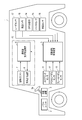
- FIG. 1 is a diagram showing an overall configuration of an automatic driving control system including a driver awakening support device as an embodiment of a driver body condition recovery support device of the present invention.
- This automatic driving control system is mounted on a vehicle 1 such as a passenger car.
- the vehicle 1 includes, as basic equipment, a power unit 2 including a power source and a transmission, and a steering device 3 equipped with a steering wheel 3a.
- a power unit 2 including a power source and a transmission
- a steering device 3 equipped with a steering wheel 3a.
- An engine and / or a motor is used as the power source.
- the vehicle 1 is configured to be able to travel in either the manual operation mode or the automatic operation mode.
- the manual driving mode is a mode in which the vehicle 1 is driven mainly by a driver's manual driving operation, for example.
- the manual operation mode includes, for example, an operation mode for driving the vehicle based only on the driver's driving operation, and an operation mode for performing driving operation support control for supporting the driving operation of the driver while mainly driving the driver's driving operation. Is included.
- the driving operation support control assists the steering torque so that the driver's steering becomes an appropriate steering amount based on the curvature of the curve when the vehicle 1 is traveling on the curve, for example.
- the driving operation support control includes control for assisting a driver's accelerator operation (for example, operation of an accelerator pedal) or brake operation (for example, operation of a brake pedal), manual steering (manual operation of steering), and manual speed adjustment (speed). Adjustment manual operation) is also included.
- a driver's accelerator operation for example, operation of an accelerator pedal
- brake operation for example, operation of a brake pedal
- manual steering manual operation of steering
- speed manual speed adjustment
- Adjustment manual operation is also included.
- manual steering the vehicle 1 is steered mainly by the driver's operation of the steering wheel 3a.
- the manual speed adjustment the speed of the vehicle is adjusted mainly by the driver's accelerator operation or brake operation.
- the driving operation support control does not include control for forcibly intervening in the driving operation of the driver and automatically driving the vehicle.
- the driving operation of the driver is reflected in the driving of the vehicle within a preset allowable range, but forcibly intervenes in the driving of the vehicle under certain conditions (for example, deviation from the lane of the vehicle). Control to do is not included.
- the automatic operation mode is a mode that realizes an operation state in which the vehicle automatically travels along the road on which the vehicle travels, for example.
- the automatic driving mode includes, for example, a driving state in which the vehicle automatically travels toward a preset destination without driving by the driver.
- the automatic driving mode it is not always necessary to automatically control all of the vehicle, and the driving state in which the driving operation of the driver is reflected in the driving of the vehicle within the preset allowable range is also included in the automatic driving mode. That is, the automatic driving mode includes control for forcibly intervening in driving of the vehicle under certain conditions, while reflecting the driving operation of the driver in driving of the vehicle within a preset allowable range.
- the vehicle 1 is also provided with an automatic driving control device 5 for executing driving control in the automatic driving mode.
- the automatic driving control device 5 acquires sensing data from a steering sensor 11, an accelerator pedal sensor 12, a brake pedal sensor 13, a GPS (Global Positioning System) receiver 14, a gyro sensor 15, and a vehicle speed sensor 16, respectively.
- the automatic driving control device 5 is a peripheral monitoring system that monitors these sensing data, route information generated by a navigation system (not shown), traffic information acquired by road-to-vehicle communication, and the positions and movements of surrounding people and vehicles.
- the vehicle 1 is automatically controlled based on the information obtained by the above.
- the surrounding monitoring system for example, measures a distance from a surrounding vehicle and outputs distance information to the automatic driving control device 5, and images the surroundings of the vehicle and outputs a video signal thereof to the automatic driving control device 5.
- a peripheral camera 18 for a distance from a surrounding vehicle and outputs distance information to the automatic driving control device 5 and images the surroundings of the vehicle and outputs a video signal
- Automatic control includes, for example, automatic steering (automatic steering operation) and automatic speed adjustment (automatic driving of speed).
- Automatic steering is an operating state in which the steering device 3 is automatically controlled.
- Automatic steering includes LKA (Lane Keeping Assist).
- LKA Li Keeping Assist
- the LKA automatically controls the steering device 3 so that the vehicle 1 does not deviate from the traveling lane even when the driver does not perform the steering operation.
- the driver's steering operation may be reflected in the steering of the vehicle in a range where the vehicle 1 does not deviate from the travel lane (allowable range).
- automatic steering is not limited to LKA.
- Automatic speed adjustment is an operating state in which the speed of the vehicle 1 is automatically controlled.
- Automatic speed adjustment includes ACC (Adaptive Cruise Control). For example, when there is no preceding vehicle ahead of the vehicle 1, ACC performs constant speed control that causes the vehicle 1 to travel at a constant speed at a preset speed, and when the preceding vehicle exists ahead of the vehicle 1. Is a follow-up control that adjusts the vehicle speed of the vehicle 1 in accordance with the inter-vehicle distance from the preceding vehicle.
- the automatic operation control device 5 decelerates the vehicle 1 according to the driver's brake operation (for example, operation of the brake pedal) even when ACC is being executed.
- the automatic operation control device 5 can perform the driver's accelerator operation (for example, accelerator) up to a preset maximum allowable speed (for example, the maximum speed legally determined on the traveling road) even during execution of ACC.
- the vehicle can be accelerated according to the pedal operation.
- the automatic speed adjustment is not limited to ACC but also includes CC (Cruise Control).
- the automatic operation control system of the present embodiment has a driver monitoring system 10 that monitors the driver.
- the driver monitoring system 10 includes a driver awakening support device 6 that promotes a driver's awakening, a driver camera 7 as a driver state detection sensor that detects a driver's state, and an awakening from the driver awakening support device 6.
- a guidance output device 8 for outputting guidance information for assistance.
- the driver camera 7 is installed at a position in front of the driver, such as on the dashboard, for example, and images the driver and outputs the video signal to the driver awakening support device 6.
- the guidance output device 8 has, for example, a speaker and a display, and outputs a voice signal of guidance information output from the driver awakening support device 6 from the speaker and also displays a display signal of guidance information on the display.
- the guidance output device 8 may be configured by one of a speaker and a display.
- the guidance output device 8 may be configured using an image display function or a voice output function of the navigation system.
- FIG. 2 is a block diagram showing the functional configuration.
- the driver awakening support device 6 includes a control unit 61, an input / output interface unit 62, and a storage unit 63.
- the input / output interface unit 62 receives the video signal output from the driver camera 7, converts it into digital data, and inputs the digital data to the control unit 61.
- the input / output interface unit 62 also receives the operation mode information and the stability information output from the automatic operation control device 5 and inputs them to the control unit 61.
- the input / output interface unit 62 further converts the guidance information output from the control unit 61 into a voice signal and a display signal, and outputs them to the guidance output device 8.
- the storage unit 63 uses, as a storage medium, a non-volatile memory that can be written and read at any time, such as an SSD (Solid State Drive) or an HDD (Hard Disk Drive).
- the storage unit 63 includes a driver monitoring video storage unit 631 that stores a driver's monitoring video and a driver state storage unit 632 that stores a driver's status as storage areas used to implement the present embodiment. And a guide information storage unit 633 storing guide information.
- the control unit 61 has a CPU (Central Processing Unit) and a program memory constituting the computer.
- the control unit 61 includes an automatic driving determination unit 611, a driver monitoring video acquisition unit 612, a driver state determination unit 613, a stability determination unit 614, as control functions necessary for carrying out this embodiment.
- a guidance output unit 615 can be realized by causing the CPU to execute a program stored in the program memory.
- the automatic driving determination unit 611 determines whether the vehicle 1 is currently traveling in the manual driving mode or the automatic driving mode based on the driving mode information output from the automatic driving control device 5. have.
- the control unit 61 performs the present embodiment by using the driver monitoring image acquisition unit 612, the driver state determination unit 613, the stability determination unit 614, and the guidance output unit 615. To work.
- the driver monitoring video acquisition unit 612 has a function of acquiring a driver monitoring video from the driver camera 7.
- the driver monitoring video acquisition unit 612 takes in the digital data (driver monitoring video data) of the video signal of the driver output from the driver camera 7 from the input / output interface unit 62, and uses the captured driver monitoring video data.
- the information is stored in the driver monitoring video storage unit 631 of the storage unit 63.
- the driver state determination unit 613 has a function of determining the state of the driver.
- the driver state determination unit 613 reads the driver monitoring video data from the driver monitoring video storage unit 631 at a preset time interval. Next, every time the driver monitoring video data is read, the driver status determination unit 613 performs a process of determining the driver status based on the driver monitoring video data.
- the driver state determination unit 613 stores the determination result in the driver state storage unit 632.
- the stability determination unit 614 has a function of determining whether the stability of the current automatic driving is high based on the stability information output from the automatic driving control device 5.
- the guidance output unit 615 has a function of reading the guidance information stored in advance from the guidance information storage unit 633 and outputting the guidance information to the guidance output device 8. Which guidance information the guidance output unit 615 reads and outputs from the guidance information storage unit 633 depends on the determination result of the driver state determination unit 613 stored in the driver state storage unit 632 and the stability determination unit. This is determined according to the determination result at 614.
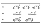
- the driving environment assumed in this embodiment is, for example, as follows.
- FIG. 4 schematically shows such an operating environment.
- a vehicle C1 represents a vehicle traveling in the manual operation mode
- a vehicle C2 represents a vehicle traveling in the automatic operation mode.
- the vehicle C1 is referred to as a manually driven vehicle C1
- the vehicle C2 is referred to as an automatically driven vehicle C2.
- the lane TL1 represents a so-called traveling lane, and is located on the side where the service area, the parking area, and the interchange side road are located.
- Lane TL2 represents a so-called overtaking lane.
- the lane TL3 represents an automatic driving permission lane in which traveling in the automatic driving mode is permitted.
- the autonomous driving vehicle C2 exists only in the lane TL3.
- the driver In this driving environment, the driver is allowed to concentrate on something other than driving to some extent while driving in the automatic driving mode. However, when the destination is approaching, that is, when the interchange to get off is approaching, the driver needs to finish traveling in the automatic operation mode and switch to traveling in the manual operation mode.
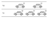
- FIG. 5 schematically shows such an operating environment.
- the lane TL1 represents a so-called traveling lane, and is located on the side where the service area, the parking area, and the interchange side road are located.
- Lane TL2 represents a so-called overtaking lane.
- a manual driving vehicle C1 and an automatic driving vehicle C2 are mixed.
- the driver In this driving environment, the driver is allowed to concentrate to something other than driving to some extent while driving in the automatic driving mode. However, when the destination is approaching, that is, when the interchange to get off is approaching, the driver needs to finish traveling in the automatic operation mode and switch to traveling in the manual operation mode.
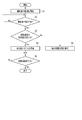
- FIG. 3 is a flowchart showing the procedure and details of driver awakening support.
- This flowchart is based on the fact that the automatic driving determination unit 611 of the driver awakening support device 6 determines that the automatic driving control device 5 has started automatic driving based on the driving mode information from the automatic driving control device 5. Start.
- driver monitoring system 10 starts monitoring the driver in step S1.
- Driver monitoring continues, for example, during automatic driving.
- the driver is monitored as follows, for example.
- the driver camera 7 When the automatic driving is started, the driver camera 7 is activated, and continuously captures a predetermined range including the driver's face and outputs the video signal.
- the driver awakening support device 6 receives digital data (driver monitoring video data) of the video signal output from the driver camera 7 from the input / output interface unit 62 under the control of the driver monitoring video acquisition unit 612.
- the captured driver monitoring video data is stored in the driver monitoring video storage unit 631 of the storage unit 63.
- the driver's imaging may be performed intermittently at predetermined time intervals.
- the driver camera 7 or the input / output interface unit 62 may encode the video signal according to a predetermined encoding method. In this way, it is possible to reduce the information amount of the monitoring video data and save the storage capacity of the driver monitoring video storage unit 631.
- the driver awakening support device 6 next passes a certain time under the control of the driver state determination unit 613 in step S2. Each time is determined, the state of the driver is determined.
- the time interval for determining the driver's state may be set to a short interval such as about 1 second so that a substantially continuous determination can be performed, or set to a relatively long interval such as 10 to 30 seconds. It may be.
- the determination of the driver's state is performed as follows, for example.
- the driver state determination unit 613 reads the driver monitoring video data from the driver monitoring video storage unit 631 and determines the state of the driver based on the driver monitoring video data.
- the driver state determination unit 613 stores information indicating the determination result in the driver state storage unit 632 in association with information indicating the determination timing, for example, time stamp information.
- the state of the driver determined by the driver state determination unit 613 is whether or not the body condition is lowered. Specifically, in this embodiment, whether or not the driver is drowsy.
- the determination of the driver's state is performed as follows, for example.
- the driver state determination unit 613 recognizes the driver's arousal level by detecting the open state of the driver's eyes, the blinking frequency, the eye movement, and the like based on the driver monitoring video data. Next, the driver state determination unit 613 compares the driver's arousal level with a preset arousal level threshold value to determine whether or not the driver's physical condition is reduced, that is, the driver is drowsy. Determine whether or not.
- the preset arousal level threshold is determined by deep learning of driver monitoring video data for a large number of subjects, or established academically, and the driver is drowsy. It may be set to the degree of awakening.
- step S3 Determination of Stability
- the driver awakening support device 6 is determined in step S3. Determines whether the stability is high under the control of the stability determination unit 614. The determination of the stability is performed as follows, for example.
- the stability determination unit 614 of the driver awakening support device 6 determines the stability of automatic driving indicated by the stability information received from the automatic driving control device 5 via the input / output interface unit 62 as a preset stability threshold value. To determine whether or not the stability of the automatic driving is high.
- the automatic operation control device 5 determines whether or not to continue the automatic operation as disclosed in, for example, Japanese Patent Application Laid-Open No. 2015-032291.
- the control limit which is a condition in which support is restricted by a limit on control performance
- the recognition limit which is a condition in which support is restricted by a limit on recognition performance
- the condition in which support is restricted by a limit on processing performance is determined based on the three kinds of conditions of the processing limit.
- the control limit for example, automatic driving is continued when another vehicle has not suddenly interrupted in front of the vehicle during follow-up traveling, or when sufficient deceleration can be achieved despite sudden deceleration of the preceding vehicle.
- the recognition limit for example, when the wiper is not operated at high speed, or when the dirt of the peripheral camera 18 is not detected, the surrounding environment acquired by the peripheral camera 18 is good, for example, no fog is generated.
- the reliability of the radar sensor 17 is high, the automatic operation is continued.
- the processing limit for example, when it is not in a state where the original automatic travel support cannot be performed due to abnormality of various sensors or CPU, the automatic operation is continued with high reliability.
- the automatic operation control device 5 determines whether or not the respective conditions are satisfied by comparing the measured values for each of the three types of conditions used for the continuation determination of the automatic operation with the respective threshold values.
- the automatic driving control device 5 outputs those measured values to the driver awakening support device 6 as stability information indicating the stability.
- the automatic operation control device 5 may output these measurement values as stability information as they are, but adds them together, averages them, or takes a weighted average weighted for each condition. Etc. Further, for example, only one condition such as a measurement value for the recognition limit may be output as the stability information.
- the stability determination unit 614 of the driver awakening support device 6 compares the stability information input from the automatic driving control device 5 with preset stability threshold information, thereby increasing the stability of automatic driving. It is determined whether or not.
- the preset stability threshold is obtained by deep learning of stability data for a large number of driving situations, or has been established academically, and can be determined to be stable automatic driving. May be set in degrees.
- the driver awakening support device 6 controls the body under the control of the guidance output unit 615 in step S4.
- Guidance information suggesting that the user is moving is transmitted to the guidance output device 8. In this case, it suggests a movement that moves the whole body, which can improve the arousal level, rather than a local movement such as a leg tip. More specifically, it suggests that the driver performs body stretching exercises.
- guidance information that suggests that the driver performs body stretching exercises is stored in advance in the guidance information storage unit 633, and the guidance output unit 615 reads out the guidance information from the guidance information storage unit 633 and outputs it. To do.
- the guidance information that suggests that the driver performs body stretching exercises may be content such as “please perform body stretching exercises”, for example.
- the guidance information that suggests that the driver is to stretch the body is converted into an audio signal and / or a display signal in the input / output interface unit 62 and output to the guidance output device 8.
- the guidance output device 8 outputs a voice signal from a speaker as a voice message, for example.
- the guidance output device 8 may display the display signal on the display device as a display message.
- the driver awakening support device 6 determines that the driver is not stretched under the control of the guidance output unit 615 in step S5.
- Guide information other than the guide information suggesting that exercise is performed is transmitted to the guide output device 8.
- this guidance information is stored in advance in the guidance information storage unit 633, and the guidance output unit 615 reads out the guidance information indicating the warning message from the guidance information storage unit 633 and outputs it.
- the guidance information indicating the warning message may be, for example, contents such as “It seems to be drowsy. Be careful.” Or “Please do not sleep.”
- the guidance information indicating the warning message is converted into an audio signal and / or a display signal in the input / output interface unit 62 and output to the guidance output device 8.
- the guidance output device 8 outputs a voice signal from a speaker as a voice message, for example.
- the guidance output device 8 may display the display signal on the display device as a display message.
- a message may be a warning sound or music, and is not limited to a sound.
- it may be a vibration of a driver's seat or a vibrator provided on the steering wheel 3a.
- the driver utters the predetermined voice, that is, Active stimulation may be applied.
- guidance information for performing an exercise of moving only the tip of the leg for example, which can be performed without removing the hand from the steering wheel may be output.
- step S2 determines that the driver is not drowsy in step S2, and after outputting the guidance information in step S4 or step S5, step In S6, it is determined whether or not the automatic operation is finished. This is because the automatic driving determination unit 611 of the driver awakening support device 6 determines whether or not the automatic driving control device 5 finishes the automatic driving and returns to the manual driving based on the driving mode information from the automatic driving control device 5. Judgment by
- step S2 If it is determined that the automatic operation has not ended, the process returns to step S2. If it is determined that the automatic operation has ended, the process ends.
- the driver state determination unit 613 determines whether or not the driver's body condition is lowered by the driver state determination unit 613 during the automatic driving in the automatic driving mode. Determine whether it is hosting. Then, when it is determined that the driver is drowsy, the driver awakening support that suggests an active stimulus, in particular, suggests that the body stretches, is performed. That is, during automatic driving, the driver does not need to perform a driving operation of the vehicle, and thus can perform various exercises using the whole body, such as body stretching exercises. Therefore, it is suggested that when the driver is drowsy during automatic driving, he / she performs body stretching exercises. This makes it possible for the driver to execute such body stretching exercise, and the driver's arousal level can be further increased.
- the body stretching movement is a posture in which the hand is away from the steering wheel and the foot is away from the accelerator pedal or the brake pedal, so it may not always be performed during automatic driving. Therefore, according to one embodiment of the present invention, switching between the suggestion of such body stretching movement and the other awakening support is output according to the stability of automatic driving. That is, it suggests that the body stretches only when the stability of automatic driving is high. In other words, it is judged by the stability of automatic driving whether or not it is safe to get away from the steering wheel, feet from the accelerator pedal or brake pedal, and only when it is safe Suggest to do such exercise.
- the awakening support can be performed while ensuring safety.
- the driver state detection sensor is configured by the driver camera 7 and the driver state is determined based on an image signal including the driver's face obtained by the driver camera 7 will be described as an example. did.
- the driver state detection sensor is not limited to the driver camera 7, and is configured by a biological sensor that acquires biological information of the driver, and based on a biological signal obtained by the biological sensor, for example, by a pulse wave sensor or a heart rate sensor.
- the state of the driver may be determined based on the detected pulse wave signal or heartbeat signal of the driver or a signal representing the vertical movement of the diaphragm detected by the pressure sensor.
- the driver when the driver is drowsiness other than during automatic driving, that is, during manual driving, the driver may be awakened by the output of a passive stimulus when the driver is drowsy.
- the driver when the driver is drowsiness other than during automatic driving, that is, during manual driving, the driver may be awakened by the output of a passive stimulus when the driver is drowsy.
- the driver state detection sensor is configured with a sensor biosensor, so that the driver affects the driving operation other than sleepiness, such as the driver's fatigue and the degree of stiffness of the shoulder and neck. It is possible to detect a decrease in body condition. Therefore, as the driver state determined by the driver state determination unit 613, it may be determined whether or not the driver is drowsy and whether or not the shoulder or neck is stuck. As a result, the guidance output unit 615 releases the hand from the steering wheel only when the stability of the automatic driving is high when the driver's shoulder or neck is stuck during automatic driving in the automatic driving mode. It is possible to provide support for relieving stiff shoulders and necks by suggesting exercises that turn the shoulders and turn the head that shakes the line of sight from the direction of travel. That is, the driver body condition recovery support device may be a driver stiffness elimination support device.
- the present invention can provide a driver body condition recovery support device that can support recovery without deteriorating safety against various driver body condition drops.
- the vehicle type, the function of the automatic driving control device, the driver physical condition recovery support procedure and the support content of the driver physical condition recovery support device, etc. are variously modified and implemented without departing from the gist of the present invention. Is possible.
- the present invention is not limited to the above-described embodiment as it is, and can be embodied by modifying the constituent elements without departing from the scope of the invention in the implementation stage.
- various inventions can be formed by appropriately combining a plurality of constituent elements disclosed in the embodiment. For example, some components may be deleted from all the components shown in the embodiment. Furthermore, you may combine suitably the component covering different embodiment.
- a driver physical condition recovery support device which is mounted on a vehicle having an automatic driving control device and supports recovery of a lowered physical condition of the driver when the vehicle is in an automatic driving mode, comprising a hardware processor and a memory And The hardware processor is During the automatic driving of the vehicle, the sensing result of a driver state detection sensor that detects the state of the driver of the vehicle is stored in the memory, and based on the sensing result, the body condition of the driver is determined, A driver that changes a stimulus given to the driver based on a stability of automatic driving by the automatic driving control device when it is determined that the physical condition of the driver is lower than a preset physical condition threshold value; Body condition recovery support device.
- a driver physical condition recovery support method that is mounted on a vehicle having an automatic driving control device and that is executed by an apparatus for supporting recovery of a reduced physical condition of the driver during the automatic driving mode of the vehicle, Using a hardware processor, during the automatic driving of the vehicle, a sensing result of a driver state detection sensor that detects the state of the driver of the vehicle is stored in a memory, and based on the sensing result, the body of the driver Judge the condition, When it is determined that the driver's physical condition is lower than a preset physical condition threshold using the hardware processor, the driver is determined based on the stability of automatic driving by the automatic driving control device.
- a driver's physical condition recovery support method that changes the stimulus given.
Abstract
La présente invention concerne un dispositif de support de réveil de conducteur pourvu : d'une unité de détermination de stabilité qui détermine la stabilité de la conduite automatique au moyen d'un dispositif de commande de conduite automatique ; d'une unité de détermination d'état de corps qui détermine l'état du corps d'un conducteur sur la base d'un résultat de détection provenant d'un capteur de détection d'état de conducteur qui détecte l'état du conducteur du véhicule ; et d'une unité de support de récupération d'état de corps qui fournit, au conducteur, un support de récupération d'état de corps, lorsque l'état du corps du conducteur est déterminé comme ayant chuté au-dessous d'une valeur seuil d'état de corps prédéfinie par l'unité de détermination d'état de corps. L'unité de support de récupération d'état de corps change, sur la base de la stabilité de la conduite automatique qui est déterminée par l'unité de détermination de stabilité, la stimulation donnée au conducteur en tant que support de récupération d'état de corps.
Applications Claiming Priority (2)
| Application Number | Priority Date | Filing Date | Title |
|---|---|---|---|
| JP2017-041900 | 2017-03-06 | ||
| JP2017041900A JP2018147247A (ja) | 2017-03-06 | 2017-03-06 | 運転者身体コンディション回復支援装置、方法およびプログラム |
Publications (1)
| Publication Number | Publication Date |
|---|---|
| WO2018163536A1 true WO2018163536A1 (fr) | 2018-09-13 |
Family
ID=63448504
Family Applications (1)
| Application Number | Title | Priority Date | Filing Date |
|---|---|---|---|
| PCT/JP2017/042566 WO2018163536A1 (fr) | 2017-03-06 | 2017-11-28 | Dispositif, procédé et programme de support de récupération d'état de corps de conducteur |
Country Status (2)
| Country | Link |
|---|---|
| JP (1) | JP2018147247A (fr) |
| WO (1) | WO2018163536A1 (fr) |
Cited By (1)
| Publication number | Priority date | Publication date | Assignee | Title |
|---|---|---|---|---|
| CN113168772A (zh) * | 2018-11-13 | 2021-07-23 | 索尼集团公司 | 信息处理装置,信息处理方法和程序 |
Citations (4)
| Publication number | Priority date | Publication date | Assignee | Title |
|---|---|---|---|---|
| JP2005352895A (ja) * | 2004-06-11 | 2005-12-22 | Kenwood Corp | 車両運転者覚醒システム |
| WO2007011060A1 (fr) * | 2005-07-20 | 2007-01-25 | Toyota Jidosha Kabushiki Kaisha | Dispositif de régulation d’état mental |
| JP2010271794A (ja) * | 2009-05-19 | 2010-12-02 | Fuji Heavy Ind Ltd | 運転行動誘導システム |
| JP2016130971A (ja) * | 2015-01-14 | 2016-07-21 | 日立オートモティブシステムズ株式会社 | 車載用制御装置、自車位置姿勢特定装置、車載用表示装置 |
Family Cites Families (2)
| Publication number | Priority date | Publication date | Assignee | Title |
|---|---|---|---|---|
| JP6142718B2 (ja) * | 2013-07-31 | 2017-06-07 | 株式会社デンソー | 運転支援装置、および運転支援方法 |
| CN106233356B (zh) * | 2014-04-25 | 2018-11-13 | 日产自动车株式会社 | 信息呈现装置以及信息呈现方法 |
-
2017
- 2017-03-06 JP JP2017041900A patent/JP2018147247A/ja active Pending
- 2017-11-28 WO PCT/JP2017/042566 patent/WO2018163536A1/fr active Application Filing
Patent Citations (4)
| Publication number | Priority date | Publication date | Assignee | Title |
|---|---|---|---|---|
| JP2005352895A (ja) * | 2004-06-11 | 2005-12-22 | Kenwood Corp | 車両運転者覚醒システム |
| WO2007011060A1 (fr) * | 2005-07-20 | 2007-01-25 | Toyota Jidosha Kabushiki Kaisha | Dispositif de régulation d’état mental |
| JP2010271794A (ja) * | 2009-05-19 | 2010-12-02 | Fuji Heavy Ind Ltd | 運転行動誘導システム |
| JP2016130971A (ja) * | 2015-01-14 | 2016-07-21 | 日立オートモティブシステムズ株式会社 | 車載用制御装置、自車位置姿勢特定装置、車載用表示装置 |
Cited By (1)
| Publication number | Priority date | Publication date | Assignee | Title |
|---|---|---|---|---|
| CN113168772A (zh) * | 2018-11-13 | 2021-07-23 | 索尼集团公司 | 信息处理装置,信息处理方法和程序 |
Also Published As
| Publication number | Publication date |
|---|---|
| JP2018147247A (ja) | 2018-09-20 |
Similar Documents
| Publication | Publication Date | Title |
|---|---|---|
| JP7080598B2 (ja) | 車両制御装置および車両制御方法 | |
| JP7155122B2 (ja) | 車両制御装置及び車両制御方法 | |
| JP6699831B2 (ja) | 運転意識推定装置 | |
| JP4973551B2 (ja) | 運転者状態判定装置 | |
| JP6627811B2 (ja) | 集中度判定装置、集中度判定方法及び集中度判定のためのプログラム | |
| CN110192084B (zh) | 自动驾驶辅助装置、方法及程序 | |
| US10338583B2 (en) | Driving assistance device | |
| MX2013009434A (es) | Sistema y método de respuesta al comportamiento del conductor. | |
| WO2018168051A1 (fr) | Dispositif de détermination de degré de concentration, procédé de détermination de degré de concentration et programme de détermination de degré de concentration | |
| JP6631570B2 (ja) | 運転状態判定装置、運転状態判定方法及び運転状態判定のためのプログラム | |
| WO2008114839A1 (fr) | Dispositif et procédé d'évaluation de niveau de vigilance | |
| JP2019166968A (ja) | 状態判定装置、及び状態判定プログラム | |
| US20240000354A1 (en) | Driving characteristic determination device, driving characteristic determination method, and recording medium | |
| WO2018168049A1 (fr) | Dispositif de détermination de degré de concentration, procédé de détermination de degré de concentration, et programme de détermination de degré de concentration | |
| JP6627810B2 (ja) | 運転モード切替制御装置、方法およびプログラム | |
| JP6468306B2 (ja) | 視認支援装置、方法およびプログラム | |
| US20230278565A1 (en) | Driving assistance device | |
| WO2018163536A1 (fr) | Dispositif, procédé et programme de support de récupération d'état de corps de conducteur | |
| JP6648722B2 (ja) | 故障判定装置、方法およびプログラム | |
| JP2016053821A (ja) | 車載システム | |
| WO2018168046A1 (fr) | Dispositif de détermination de niveau de concentration, procédé de détermination de niveau de concentration, et programme de détermination de niveau de concentration | |
| WO2018168048A1 (fr) | Dispositif de détermination de degré de concentration, procédé de détermination de degré de concentration, et programme permettant de déterminer un degré de concentration | |
| WO2018168050A1 (fr) | Dispositif de détermination de niveau de concentration, procédé de détermination de niveau de concentration, et programme permettant de déterminer le niveau de concentration | |
| JP2021014235A (ja) | 車両用通知制御装置及び車両用通知制御方法 | |
| JP2022127881A (ja) | 運転状態検出方法 |
Legal Events
| Date | Code | Title | Description |
|---|---|---|---|
| 121 | Ep: the epo has been informed by wipo that ep was designated in this application |
Ref document number: 17899674 Country of ref document: EP Kind code of ref document: A1 |
|
| NENP | Non-entry into the national phase |
Ref country code: DE |
|
| 122 | Ep: pct application non-entry in european phase |
Ref document number: 17899674 Country of ref document: EP Kind code of ref document: A1 |