WO2018163314A1 - トーションビーム式サスペンション及びそれに使用するリインフォースメントメンバ - Google Patents
トーションビーム式サスペンション及びそれに使用するリインフォースメントメンバ Download PDFInfo
- Publication number
- WO2018163314A1 WO2018163314A1 PCT/JP2017/009221 JP2017009221W WO2018163314A1 WO 2018163314 A1 WO2018163314 A1 WO 2018163314A1 JP 2017009221 W JP2017009221 W JP 2017009221W WO 2018163314 A1 WO2018163314 A1 WO 2018163314A1
- Authority
- WO
- WIPO (PCT)
- Prior art keywords
- torsion beam
- reinforcement member
- distal end
- end side
- protrusion
- Prior art date
- Legal status (The legal status is an assumption and is not a legal conclusion. Google has not performed a legal analysis and makes no representation as to the accuracy of the status listed.)
- Ceased
Links
Images


Classifications
-
- B—PERFORMING OPERATIONS; TRANSPORTING
- B60—VEHICLES IN GENERAL
- B60G—VEHICLE SUSPENSION ARRANGEMENTS
- B60G7/00—Pivoted suspension arms; Accessories thereof
-
- B—PERFORMING OPERATIONS; TRANSPORTING
- B60—VEHICLES IN GENERAL
- B60G—VEHICLE SUSPENSION ARRANGEMENTS
- B60G9/00—Resilient suspensions of a rigid axle or axle housing for two or more wheels
- B60G9/04—Resilient suspensions of a rigid axle or axle housing for two or more wheels the axle or housing not being pivotally mounted on the vehicle
Definitions
- the present invention relates to a torsion beam suspension and a reinforcement member (reinforcing material) used therein.
- the torsion beam suspension is mainly used for the rear wheel of a front wheel drive vehicle.
- a torsion beam which is a long member, is fixed between a pair of left and right trailing arms. Wheels are supported on the trailing arm. When the wheel is displaced by unevenness on the road surface or the like, the torsion beam is twisted or bent and elastically deformed to allow the trailing arm to be displaced. When the road surface becomes flat, the torsion beam returns to its original shape, and the trailing arm and wheels are returned to their original positions.
- Patent Document 1 discloses a torsion beam suspension including a torsion beam having a low-rigidity portion having a U-shaped cross-section and a highly elastic portion having a U-shaped cross-sectional shape. A reinforcing material is joined to the torsion beam so as to avoid a highly rigid portion.
- Patent Document 2 discloses a torsion beam suspension in which the cross-sectional shape near the center of the torsion beam is U-shaped and the cross-sectional shape on the end side of the torsion beam is V-shaped. It is described that the torsion beam is supported from the bottom side by two reinforcements and supported by sandwiching the torsion beam from one plane by one reinforcement.
- the edges of the side plate (reference numeral 64) and the substrate (reference numeral 62) are welded to join the reinforcing material and the torsion beam.
- the side plate and the substrate are difficult to follow the torsion beam torsion and deflection, and when the torsion beam is torsioned and bent, the torsion beam and the reinforcing material are easily separated at the welded portion.
- the torsion beam suspension of Patent Document 2 if the torsion beam is twisted or bent, stress may concentrate on the tip of the reinforcement and the torsion beam may be cracked.
- a torsion beam suspension comprising a certain reinforcement member, wherein the reinforcement member has a plate shape and is provided with a tapered portion and a divided portion on the distal end side, and the shape on the distal end side of the reinforcement member is a tapered portion.
- the distal end is divided into a plurality of protrusions by the dividing portion, and the inclination angle of the protrusion is loosened in the middle
- the torsion beam suspension that has an inflection part on the projection that changes the angle It is decided.
- Reinforcement member for a torsion beam suspension having a proximal end portion for fixing to a trailing arm and a distal end portion for fixing to a torsion beam.
- the shape of the distal end side of the reinforcement member is a proximal end by a tapered portion.
- the width of the tip side is gradually reduced with respect to the width of the side, the tip portion is divided into a plurality of protrusions by the dividing portion, and the angle is set so that the inclination angle of the protrusion becomes loose in the middle.
- the reinforcement member has an inflection portion on the protrusion. Accordingly, when the torsion beam is twisted or bent, the stress applied to the contact point between the distal end side of the reinforcement member and the torsion beam can be dispersed to prevent the torsion beam from being broken and damaged.
- the reinforcement member is provided with a through hole in a root portion of the protrusion.
- the protrusion is composed of a tapered portion that is inclined in a direction narrower than the width on the proximal end side of the reinforcement member, an inflection portion, and a distal end portion.
- the stress applied to the tip portion by the inflection portion can be dispersed and reduced.
- the length from the point on the proximal end of the projection where the distal end side of the reinforcement member contacts the torsion beam to the distal end of the reinforcement member is L1, and the length from the contact point to the inflection portion is L2.
- the torsion beam has a flat surface and is preferably fixed in a state where the tip side of the reinforcement member is in contact with the flat surface.
- the reinforcement member and the torsion beam are welded to each other on the outer side of the distal end portion, the inflection portion, and the taper portion, and on the proximal end side of the divided portion.
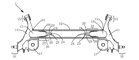
- FIG. 2 is an enlarged bottom view of a part of the torsion beam suspension of FIG. 1.
- the blacked out area is the area where the torsion beam and the reinforcement member are in contact with each other (the same applies to FIGS. 8 to 13).
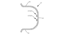
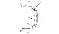
- FIG. 3 is an end view of a BB portion in FIG. 2.
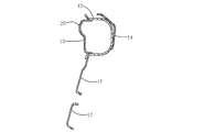
- FIG. 3 is an end view of a DD portion in FIG. 2.
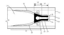
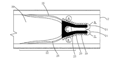
- FIG. 3 is an enlarged view of an enlarged bottom surface of the torsion beam suspension according to the first embodiment.
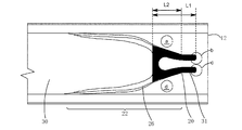
- FIG. 5 is an enlarged view of an enlarged bottom surface of a torsion beam suspension according to a second embodiment.
- FIG. 6 is an enlarged view of an enlarged bottom surface of a torsion beam suspension according to a third embodiment.
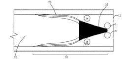
- 5 is an enlarged view of an enlarged bottom surface of a torsion beam suspension according to Comparative Example 1.
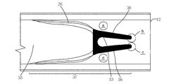
- FIG. 6 is an enlarged view in which a bottom surface of a torsion beam suspension according to Comparative Example 2 is enlarged.
- FIG. 9 is an enlarged view of a bottom surface of a torsion beam suspension according to a fourth embodiment.
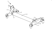
- the torsion beam suspension 1 includes a pair of left and right trailing arms 11, a torsion beam 12 having one end and the other end fixed to the trailing arm 11, and a pair of reinforcements fixed to the bottom side of the trailing arm 11 and the torsion beam 12. And a second reinforcement member 14 fixed to the plane side of the trailing arm 11 and the torsion beam 12.
- the trailing arm 11 includes a bush 15 disposed outside the end portion on the vehicle front side, and a wheel support portion 16 disposed outside the end portion on the vehicle rear side. And a bracket 17 for receiving a lower end of a suspension coil (not shown).
- the torsion beam suspension 1 is attached to a vehicle-side member via a bush 15 so as to be swingable in the vertical direction.
- the trailing arm 11 is formed by bending two bent steel plates by welding to form a curved shape with a recessed central portion in plan view. For this reason, the trailing arm 11 is a hollow member.
- the torsion beam 12 has a substantially U-shaped cross section including a flat surface 18 and a pair of flanges 38 protruding from the flat surface 18 to the lower side of the vehicle. Is bent outward and this cross-sectional shape is continuous in the longitudinal direction. As shown in FIG. 1, one end and the other end of the torsion beam 12 are fixed to the central portions of the right and left trailing arms 11 by welding, respectively.
- the reinforcement member 13 has a proximal end fixed to the bottom surface side of the trailing arm 11 and a distal end fixed to the bottom surface side of the torsion beam 12.
- the reinforcement member 13 is a plate-like member that is inclined from the proximal end side toward the distal end side, and the proximal end portion is fixed to the bottom surface side of the central portion of the trailing arm 11 by welding. Is done.
- the tip is fixed to the flat surface 18 on the bottom side of the torsion beam 12 by welding.
- the distal end side of the reinforcement member 13 has the distal end portion 19, the inflection portion 20, and the tapered portion 22, which will be described later, on the bottom surface side of the flat surface 18 of the torsion beam 12.
- the outer side of the tip side portion of the tip portion 19, the inflection portion 20, and the taper portion 22 is welded. Since the distal end portion 19, the inflection portion 20, and the distal end portion of the tapered portion 22 are not in the recessed position, the welding operation can be easily performed. As another embodiment, as shown in FIG. 13, in addition to the distal end portion of the distal end portion 19, the inflection portion 20, and the tapered portion 22, the arc portion on the proximal end side of the dividing portion 23 is also provided. When fixed by welding, it is possible to further reduce the stress applied to the tip of the reinforcement member.
- the reinforcement member 13 includes a tapered portion 22 and a divided portion 23 on the distal end side.
- the tapered portion 22 has a shape in which the width on the distal end side gradually becomes smaller than the width on the proximal end side.
- the shape on the front end side is a shape that is split into a pair of two protrusions 24 by the dividing portion 23.
- the number of the protrusions 24 is two.
- the number of divisions may be two, and the number of protrusions may be four in two pairs.
- the shape of the division part 23 is a drop shape (tear drop shape) in which the diameter increases as it approaches the base end side and the end becomes an arc.
- the width of the protrusion 24 continues substantially unchanged on the proximal end side and the distal end side of the protrusion in a plan view.
- the base end side and the distal end side of the protrusion 24 are elastically deformed so as to follow the twist or bend, thereby dispersing the stress applied to the torsion beam 12 and the reinforcement member 13. Is possible.
- the reinforcement member 13 is divided into two protrusions 22 by a dividing portion 23. For this reason, when the torsion beam 12 is twisted or bent, the individual protrusions 24 are elastically deformed independently, and the stress applied to the torsion beam 12 and the reinforcement member 13 is distributed following the torsion and deflection of the torsion beam 12. It becomes possible.
- the reinforcement member 13 has an inflection portion 20 on the projection that changes the angle so that the inclination angle of the projection 24 in the tapered portion 22 becomes loose in the middle.
- the inflection part 20 is located between the base end of the division part 23 and the tip of the protrusion 24.
- the protrusion 24 includes a tapered portion 22, an inflection portion 20, and a distal end portion 19 in order from the proximal end side of the protrusion.
- the inclination angle of the tapered portion 22 is 20 ° and ⁇ 20 ° when the line parallel to the extending direction of the torsion beam 12 is 0 °, and the inclination angle becomes 0 ° at the inflection portion 20.
- the inflection portion 20 By providing the inflection portion 20, the stress applied to the tip of the protrusion 24 when the torsion beam 12 is twisted or bent can be dispersed to reduce the stress value.
- the inflection portion is preferably one that changes the angle of the taper portion and the tip portion by 5 to 70 ° or ⁇ 5 to ⁇ 70 °, and changes the angle by 10 to 40 ° or ⁇ 10 to ⁇ 40 °. More preferably.
- the length from the proximal end point where the distal end side of the reinforcement member 13 is in contact with the torsion beam 12 to the distal end of the reinforcement member 13 is L1, and the length from the contacted point changes. It is preferable to arrange the inflection part 20 in a range where L1 / L2 is 1.4 or more when the length to the bending part 20 is L2.
- L1 / L2 is 1.4 or more
- the stress applied to the tip of the protrusion 24 when the torsion beam 12 is twisted or bent can be dispersed to reduce the stress value. If the ratio is excessively large, the length of the tip 19 becomes excessively large and welding becomes complicated, so the upper limit is preferably 10, and the upper limit is more preferably 5.
- L2 is not particularly limited, but is preferably 20 to 100 mm, for example.
- the reinforcement member 13 includes a bulging portion 25 for reinforcement on the proximal end side connected to the trailing arm.
- the bulging portion 25 is formed by pressing or bending. To do.
- the bulging portion 25 can improve the rigidity on the proximal end side of the reinforcement member 13.
- it is processed into a shape that gradually descends from the proximal end side toward the distal end side by pressing or bending.
- a rib 26 is provided on the distal end side of the reinforcement member 13 by pressing or bending, and the reinforcement member 13 exhibits appropriate rigidity on the distal end side.
- the rib 26 is disposed along the edge of the reinforcement member 13 from the start end of the taper portion 22 to the inflection portion 20.
- the second reinforcement member 14 has a proximal end fixed to the flat side of the trailing arm 11 by welding and a distal end fixed to the flat side of the torsion beam 12.
- the second reinforcement member 14 is shorter than the reinforcement member 13 in the extending direction, and reinforces the joining portion of the trailing arm 11 and the torsion beam 12 from the plane side.
- the torsion beam suspension 1 is only an example.
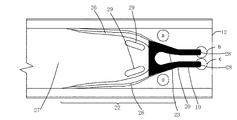
- the embodiment shown in FIG. FIG. 10 is an enlarged bottom view of the tip of the reinforcement member 27 and the bottom surface of the torsion beam 12 in the torsion beam suspension.
- the reinforcement member 27 is different from the torsion beam suspension 1 in that a hollow hole 29 is provided at the root portion of the protrusion 28.
- the root portion is located on the proximal end side of the region where the tapered portion 22 contacts the torsion beam, and does not contact the torsion beam 12.
- each of a, b, c, and d in each figure when the displacement is forcibly applied in a reverse phase is shown.
- the stress at the location was simulated.
- the torsion beam type suspensions shown in FIGS. 8, 9, 10, 11, 12, and 13 are respectively the first, second, third, comparative, first, and second examples. 4
- L1 / L2 1.7
- L1 / L2 1.3
- the reinforcement member 13 in FIG. 8 has the same configuration as the reinforcement member 13 shown in FIGS. 1 and 2, and the same applies to the point where the portions marked with “X” in FIG. 2 are welded.
- the reinforcement member 9 is different from the reinforcement member 13 in FIG. 8 in that it includes a protrusion 31 having a short length L1, and is otherwise the same as the reinforcement member 13 in FIG.
- the reinforcement member 32 in FIG. 11 does not have an inflection part on the protrusion 34, the point where the taper part 33 continues to the tip, and the protrusion 34 has no division part in FIG. 13 and different. Welding was performed along the tapered portion outside the blackened area.
- the reinforcement member 35 shown in FIG. 12 differs from the reinforcement member shown in FIG. 8 in that the tapered portion 37 continues to the tip and the inflection portion is not provided on the protrusion 36. Welding is the same as in FIG.
- the reinforcement member 39 in FIG. 13 is basically the same as the configuration of the reinforcement member in FIG.
- FIGS. 8 differs from that in FIG. 8 in that the inside of the arc portion on the base end side of the divided portion is also welded.
- the configurations of the torsion beam, the trailing arm, the second reinforcement member, etc., not shown in FIGS. 8 to 13 are the same as those in FIGS. 1 and 2, and are common to the respective examples and comparative examples.
- Example 1 the stress was reduced by about 12 to 16% at the b position and the c position as compared with Comparative Example 1. Compared with Comparative Example 2, the stress was reduced by about 18 to 22% at the b and c positions in Examples 1 and 3 as compared with the b and c positions in Comparative Example 2. In Example 2, the stress was reduced by about 10 to 11% at the b position and the c position as compared with Comparative Example 1. Compared to Comparative Example 2, the stress was reduced by about 15 to 17% at the b and c positions in Example 2 compared to the b and c positions of Comparative Example 2. In Example 3, the stress was reduced by about 8 to 10% at position a and d as compared with Example 1.
- Example 4 the stress was reduced by about 14 to 18% at the b position and the c position as compared with Comparative Example 1. Compared to Comparative Example 2, the stress was reduced by about 20 to 24% at the b and c positions in Examples 1 and 3 as compared with the b and c positions in Comparative Example 2.
- a torsion beam suspension having the configurations of Example 1, Comparative Example 1 and Comparative Example 2 was produced, and a test for forcibly repeatedly applying displacement in reverse phase was actually performed. As a result, cracking occurred in the torsion beam in Comparative Example 1 the least number of times, and then cracking occurred in the torsion beam in Comparative Example 2. In Example 1, the torsion beam was not cracked by the number of times tested in the test.
Landscapes
- Engineering & Computer Science (AREA)
- Mechanical Engineering (AREA)
- Vehicle Body Suspensions (AREA)
Abstract
【課題】 トーションビームにねじれや撓みが生じた際にリインフォースメントメンバの先端に応力が集中することを防止したトーションビーム式サスペンション及びリインフォースメントメンバを提供する。 【解決手段】 トレーリングアーム11と、トーションビーム12と、リインフォースメントメンバ13とからなるトーションビーム式サスペンション1であって、リインフォースメントメンバ13は、板状であって、先端側にテーパ部22及び分割部23を備えており、リインフォースメントメンバ13の先端側の形状は、テーパ部22によって基端側の幅に対して先端側の幅が徐々に小さくなる形状であり、分割部23によって先端が複数の突起24に分割された形状であり、突起24の傾斜角がその途中で緩くなるように角度を変化させる変曲部20を突起上に有するトーションビーム式サスペンション1である。
Description
本発明は、トーションビーム式サスペンション及びそれに使用するリインフォースメントメンバ(補強材)に関する。
トーションビーム式サスペンションは、主に前輪駆動車の後輪に用いられる。左右一対のトレーリングアームの間に長尺部材であるトーションビームを固定する。トレーリングアームには車輪が支持されている。車輪が路面の凹凸などによって変位すると、トーションビームが捩じれたり撓んだりして弾性変形しトレーリングアームが変位するのを許容する。路面が平坦になるとトーションビームが元の形状に復帰してトレーリングアーム及び車輪を元の位置に復帰させる。
特許文献1には、断面形状がU字状の低剛性部と、断面形状がコの字状の高弾性部とを有するトーションビームを備えるトーションビーム式サスペンションが開示されている。トーションビームには、高剛性部を避けるようにして、補強材が接合される。
特許文献2には、トーションビームの中央部付近の断面形状をU字状にし、トーションビームの端部側の断面形状をV字状にしたトーションビーム式サスペンションが開示されている。2本のレインフォースでトーションビームを底面側から支え、平面側から1本のレインフォースでトーションビームを挟むようにして支えることが記載されている。
特許文献1のトーションビーム式サスペンションでは、側板(符号64)及び基板(符号62)の縁を溶接して、補強材及びトーションビームを接合する。側板及び基板はトーションビームのねじれや撓みに追従し難く、トーションビームにねじれや撓みが生じた際に溶接部分においてトーションビーム及び補強材が分離しやすい。特許文献2のトーションビーム式サスペンションでは、トーションビームにねじれや撓みが生じるとレインフォースの先端に応力が集中してトーションビームに割れが生じるおそれがある。
トーションビームにねじれや撓みが生じた際にリインフォースメントメンバの先端に応力が集中することを防止したトーションビーム式サスペンション及びリインフォースメントメンバを提供することを目的とする。
左右で対であるトレーリングアームと、一端側及び他端側をトレーリングアームに固定したトーションビームと、基端側がトレーリングアームに対して固定された状態であり先端側がトーションビームに固定された状態であるリインフォースメントメンバとからなるトーションビーム式サスペンションであって、リインフォースメントメンバは、板状であって、先端側にテーパ部及び分割部を備えており、リインフォースメントメンバの先端側の形状は、テーパ部によって基端側の幅に対して先端側の幅が徐々に小さくなる形状であり、分割部によって先端が複数の突起に分割された形状であり、突起の傾斜角がその途中で緩くなるように角度を変化させる変曲部を突起上に有するトーションビーム式サスペンションによって、上記の課題を解決する。
トレーリングアームに固定するための基端部と、トーションビームに固定するための先端部と有するトーションビーム式サスペンション用のリインフォースメントメンバであって、リインフォースメントメンバの先端側の形状は、テーパ部によって基端側の幅に対して先端側の幅が徐々に小さくなる形状であり、分割部によって先端部が複数の突起に分割された形状であり、突起の傾斜角がその途中で緩くなるように角度を変化させる変曲部を突起上に有するリインフォースメントメンバによって上記の課題を解決する。
リインフォースメンバは突起の上に変曲部を備える。これにより、トーションビームにねじれや撓みが生じた際にリインフォースメンバの先端側とトーションビームの接点に掛かる応力を分散させてトーションビームが割れるなど損傷することを防止することができる。
リインフォースメントメンバは、突起の付根部分に肉抜孔を備えることが好ましい。テーパ部の付根部分に肉抜き穴を配することで、トーションビームにねじれや撓みが生じた際に突起の付根付近の部材に応力が集中することを防止することができる。
突起は、リインフォースメントメンバの基端側の幅に対して細幅となる方向に傾斜するテーパ部と、変曲部と、先端部とからなるものであることが好ましい。トーションビームにねじれや撓みが生じた際に、変曲部によって先端部に掛かる応力を分散させて低減することができる。
インフォースメントメンバの先端側がトーションビームに接面する突起の基端側の点からリインフォースメントメンバの先端までの長さをL1とし、前記接面する点から変曲部までの長さをL2としたときに、L1/L2が1.4以上となる範囲に変曲部を配することが好ましい。当該比率を1.4以上とすることで、リインフォースメントメンバの先端に掛かる応力をより低減させることができる。
トーションビームは平坦面を有しており、リインフォースメントメンバの先端側が平坦面に当接した状態で固定されることが好ましい。リインフォースメントメンバの先端側とトーションビームとを面で固定することによって、固定部分から破断することを防止することができる。
リインフォースメンバ及びトーションビームは、先端部、変曲部、及びテーパ部の外側並びに分割部の基端側において相互に溶接された状態であることが好ましい。これにより、リインフォースメントメンバの先端に係る応力をより低減させることができる。
トーションビームにねじれや撓みが生じた際にリインフォースメントメンバの先端に応力が集中することを防止したトーションビーム式サスペンション及びリインフォースメントメンバを提供することができる。
図面を参照して、本発明を実施するための形態について説明する。
図1ないし図7にトーションビーム式サスペンションの一例を示す。このトーションビーム式サスペンション1は、左右一対のトレーリングアーム11と、一端及び他端がトレーリングアーム11に固定されるトーションビーム12と、トレーリングアーム11及びトーションビーム12の底面側に固定される一対のリインフォースメントメンバ13と、トレーリングアーム11及びトーションビーム12の平面側に固定される第2リインフォースメントメンバ14からなる。
トレーリングアーム11は、図1及び図2に示したように、車両前方側の端部の外側に配されるブッシュ15と、車両後方側の端部の外側に配される車輪支持部16と、サスペンションコイル(図示略)の下端を受けるブラケット17とを備える。トーションビーム式サスペンション1はブッシュ15を介して車両側の部材に上下方向に対して揺動可能に取り付けられる。本実施形態ではトレーリングアーム11は、2枚の曲げ加工した鋼板を溶接によって接合して、平面視において中央部が窪んだ湾曲形状としている。このためトレーリングアーム11は中空の部材となっている。
トーションビーム12は、図4及び図7に示したように、平坦面18と平坦面18から車両の下方に突出する一対のフランジ38からなる略U字状の断面であり、各フランジ38の端部は外側に向けて折り曲げられており、この断面形状が長手方向に連続する。トーションビーム12の一端及び他端は、図1に示したように、それぞれ右側及び左側のトレーリングアーム11の中央部に溶接によって固定される。
リインフォースメントメンバ13は、基端がトレーリングアーム11の底面側に固定され、先端がトーションビーム12の底面側に固定される。リインフォースメントメンバー13は、図5に示したように、基端側から先端側に向けて傾斜する板状の部材であり、基端部はトレーリングアーム11の中央部の底面側に溶接によって固定される。先端部はトーションビーム12の底面側の平坦面18に溶接によって固定される。リインフォースメントメンバ13の先端側は、図2において塗りつぶして示したように、後述する先端部19、変曲部20、及びテーパ部22の先端側の部分がトーションビーム12の平坦面18の底面側に接面する。そして、図2において×印で示したように、先端部19、変曲部20、及びテーパ部22の先端側の部分の外側を溶接している。先端部19、変曲部20、及びテーパ部22の先端側の部分は奥まった位置にないので溶接作業を容易に行うことができる。また、別の実施形態として、図13に示したように、先端部19、変曲部20、及びテーパ部22の先端側の部分に加えて、分割部23の基端側の円弧の部分も溶接によって固定すると、リインフォースメントメンバの先端に掛かる応力をより低減することが可能になる。
リインフォースメントメンバ13は、先端側にテーパ部22及び分割部23を備えている。テーパ部22によって基端側の幅に対して先端側の幅が徐々に小さくなる形状となっている。先端側の形状は分割部23によって一対で2本の突起24に分割された形状となっている。本実施形態では突起24の数は2本であるが、例えば、分割部の数を2として突起の数を2対で4本としてもよい。分割部23の形状は、基端側に近づくにつれて拡径し末端は円弧となる滴形(ティアドロップ形状)となっている。このため突起24の幅は、平面視において、突起の基端側と先端側でほぼ変化なく連続する。これにより、トーションビーム12が捩じれたり撓んだりしたときに突起24の基端側と先端側をねじれや撓みに追従させるように弾性変形させてトーションビーム12及びリインフォースメントメンバ13に掛かる応力を分散させることが可能になる。
リインフォースメントメンバ13は、分割部23によって2本の突起22に分割されている。このためトーションビーム12が捩じれたり撓んだりしたときに、個々の突起24が独立に弾性変形してトーションビーム12のねじれや撓みに追従してトーションビーム12及びリインフォースメントメンバ13に掛かる応力を分散させることが可能になる。
リインフォースメントメンバ13は、テーパ部22における突起24の傾斜角がその途中で緩くなるように角度が変化させる変曲部20を突起上に有する。本実施形態では、変曲部20は分割部23の基端と突起24の先端との間に位置する。突起24は、突起の基端側から順にテーパ部22、変曲部20、先端部19となっている。本実施形態では、テーパ部22の傾斜角はトーションビーム12の延在方向に平行な線を0°としたときに20°、-20°であり、変曲部20において傾斜角が0°になりそのまま延在方向に平行な先端部19に連続する。変曲部20を設けることにより、トーションビーム12が捩じれたり撓んだりしたときに突起24の先端に掛かる応力を分散させて応力値を小さくすることができる。変曲部は、例えば、テーパ部及び先端部の角度を5~70°若しくは-5~-70°変化させるものであることが好ましく、10~40°若しくは-10~-40°変化させるものであることがより好ましい。
図8及び9に示したように、リインフォースメントメンバ13の先端側がトーションビーム12に接面する基端側の点からリインフォースメントメンバ13の先端までの長さをL1とし、前記接面する点から変曲部20までの長さをL2としたときに、L1/L2が1.4以上となる範囲に変曲部20を配することが好ましい。当該比率を1.4以上とすることでトーションビーム12が捩じれたり撓んだりしたときに突起24の先端に掛かる応力を分散させて応力値をより小さくすることができる。当該比率が過度に大きいと先端部19の長さが過度に大きくなり溶接が煩雑になるため、上限は10とすることが好ましく、上限は5とすることがより好ましい。L2は特に限定されないが、例えば20~100mmであることが好ましい。
リインフォースメントメンバ13は、図6に示したように、補強用の膨出部25をトレーリングアームに接続する基端側に備えており、例えば、プレス加工や曲げ加工によって膨出部25を形成する。膨出部25によってリインフォースメントメンバ13の基端側の剛性を向上させることができる。同様にプレス加工や曲げ加工によって、図6に示したように、基端側から先端側に向けて徐々に下降する形状に加工する。リインフォースメントメンバ13の先端側には、プレス加工や折り曲げ加工によってリブ26を設けており、先端側においてリインフォースメントメンバ13が適度な剛性を発揮するようにしてある。リブ26はテーパ部22の始端から変曲部20に至るまでリインフォースメントメンバ13の縁に沿って配される。
第2リインフォースメントメンバ14は、基端側がトレーリングアーム11の平面側に溶接によって固定され、先端側がトーションビーム12の平面側に固定される。第2リインフォースメントメンバ14は、リインフォースメントメンバ13に比べて、延在方向に対して短く、平面側からトレーリングアーム11及びトーションビーム12の接合部分を補強する。
上記のトーションビーム式サスペンション1は一例に過ぎない。例えば、図10に示した実施形態も挙げられる。図10は、トーションビーム式サスペンションにおけるリインフォースメントメンバ27の先端部とトーションビーム12の底面を拡大して示した底面図である。このリインフォースメントメンバ27は、突起28の付根部分に肉抜孔29を備える点で上記のトーションビーム式サスペンション1と異なる。付根部分は、テーパ部22がトーションビームに接面する領域の基端側に位置し、トーションビーム12とは接面しない。肉抜孔29を設けることで、トーションビーム12が捩じれたり撓んだりした際に、付根部分を変形しやすくしてテーパ部22がトーションビーム12に接面する領域(図10のa及びd)における応力を低減することができる。
図8、図9、図10、図11、図12、及び図13に示したトーションビーム式サスペンションにおいて、強制的に逆相で変位を与えた際の各図のa、b、c、dの各位置における応力をシュミレーションした。図8、図9、図10、図11、図12及び図13に示したトーションビーム式サスペンションを以下ではそれぞれ実施例1、実施例2、実施例3、比較例1、比較例2、及び実施例4とする。実施例1ではL1/L2=1.7であり、実施例2ではL1/L2=1.3である。図8のリインフォースメントメンバ13は、図1及び図2に示したリインフォースメントメンバ13と同様の構成であり、図2において×印を付した個所を溶接した点も同様である。図9のリインフォースメントメンバ30は、L1の長さが短い突起31を備える点で図8のリインフォースメントメンバ13と異なり、その他の点では図8のリインフォースメントメンバ13と同様である。図11のリインフォースメントメンバ32は、突起34上に変曲部を備えない点、テーパ部33が先端に至るまで連続する点、突起34は分割部を備えてない点で図8のリインフォースメントメンバ13と異なる。溶接は黒く塗りつぶした領域の外側のテーパ部に沿って溶接した。図12のリインフォースメントメンバ35は、テーパ部37が先端に至るまで連続する点、突起36上に変曲部を備えない点で図8のリインフォースメントメンバと異なる。溶接は図8の場合と同様である。図13のリインフォースメントメンバ39は、図8のリインフォースメンバの構成と基本的に同様であるが、分割部基端側の円弧の部分の内側も溶接した点で図8のものと相違する。なお、図8ないし図13で図示を省略したトーションビーム、トレーリングアーム、第2リインフォースメントメンバ等の構成は図1及び図2のものであり、各実施例及び比較例で共通する。
シュミレーションの結果、実施例1及び3については、b位置及びc位置で比較例1に比べて応力が12~16%程度低減された。比較例2と比較すると、実施例1及び3のb位置及びc位置では、比較例2のb位置及びc位置に比べて応力が18~22%程度低減された。実施例2では、b位置及びc位置で比較例1に比べて応力が10~11%程度低減された。比較例2と比較すると、実施例2のb位置及びc位置では、比較例2のb位置及びc位置に比べて応力が15~17%程度低減された。実施例3では、a位置及びd位置で、実施例1に比べて応力が8~10%程度低減された。実施例4については、b位置及びc位置で比較例1に比べて応力が14~18%程度低減された。比較例2と比較すると、実施例1及び3のb位置及びc位置では、比較例2のb位置及びc位置に比べて応力が20~24%程度低減された。
実施例1、比較例1及び比較例2の構成を備えるトーションビーム式サスペンションを作製して、強制的に逆相で変位を繰り返し与える試験を実際に行った。そうしたところ、比較例1が最も少ない回数でトーションビームに割れが生じ、次に比較例2のトーションビームに割れが生じた。実施例1では、試験で試した回数ではトーションビームに割れは生じなかった。
1 トーションビーム式サスペンション
11 トレーリングアーム
12 トーションビーム
13 リインフォースメントメンバ
18 平坦面
19 先端部
20 変曲部
22 テーパ部
23 分割部
24 突起
29 肉抜孔
11 トレーリングアーム
12 トーションビーム
13 リインフォースメントメンバ
18 平坦面
19 先端部
20 変曲部
22 テーパ部
23 分割部
24 突起
29 肉抜孔
Claims (7)
- 左右で対であるトレーリングアームと、
一端側及び他端側をトレーリングアームに固定したトーションビームと、
基端側がトレーリングアームに対して固定された状態であり先端側がトーションビームに固定された状態であるリインフォースメントメンバとからなるトーションビーム式サスペンションであって、
リインフォースメントメンバは、
板状であって、先端側にテーパ部及び分割部を備えており、
リインフォースメントメンバの先端側の形状は、テーパ部によって基端側の幅に対して先端側の幅が徐々に小さくなる形状であり、分割部によって先端が複数の突起に分割された形状であり、突起の傾斜角がその途中で緩くなるように角度を変化させる変曲部を突起上に有するトーションビーム式サスペンション。 - リインフォースメントメンバは、突起の付根部分に肉抜孔を備える請求項1に記載のトーションビーム式サスペンション。
- 突起は、リインフォースメントメンバの基端側の幅に対して細幅となる方向に傾斜するテーパ部と、変曲部と、先端部とからなる請求項1又は2に記載のトーションビーム式サスペンション。
- リインフォースメントメンバの先端側がトーションビームに接面する突起の基端側の点からリインフォースメントメンバの先端までの長さをL1とし、前記接面する点から変曲部までの長さをL2としたときに、
L1/L2が1.4以上となる範囲に変曲部が配された請求項1ないし3のいずれかに記載のトーションビーム式サスペンション。 - トーションビームは平坦面を有しており、リインフォースメントメンバの先端側が平坦面に当接した状態で固定されている請求項1ないし4のいずれかに記載のトーションビーム式サスペンション。
- リインフォースメンバ及びトーションビームは、先端部、変曲部、及びテーパ部の外側並びに分割部の基端側において相互に溶接された状態である請求項5に記載のトーションビーム式サスペンション。
- トレーリングアームに固定するための基端部と、トーションビームに固定するための先端部と有するトーションビーム式サスペンションのリインフォースメントメンバであって、
リインフォースメントメンバの先端側の形状は、テーパ部によって基端側の幅に対して先端側の幅が徐々に小さくなる形状であり、分割部によって先端部が複数の突起に分割された形状であり、突起の傾斜角がその途中で緩くなるように角度を変化させる変曲部を突起上に有するリインフォースメントメンバ。
Priority Applications (3)
| Application Number | Priority Date | Filing Date | Title |
|---|---|---|---|
| CN201780086055.0A CN110267831B (zh) | 2017-03-08 | 2017-03-08 | 扭力梁式悬架以及用于扭力梁式悬架的加强构件 |
| PCT/JP2017/009221 WO2018163314A1 (ja) | 2017-03-08 | 2017-03-08 | トーションビーム式サスペンション及びそれに使用するリインフォースメントメンバ |
| PH12019502026A PH12019502026A1 (en) | 2017-03-08 | 2019-09-05 | Torsion beam suspension and reinforcement member used therefore |
Applications Claiming Priority (1)
| Application Number | Priority Date | Filing Date | Title |
|---|---|---|---|
| PCT/JP2017/009221 WO2018163314A1 (ja) | 2017-03-08 | 2017-03-08 | トーションビーム式サスペンション及びそれに使用するリインフォースメントメンバ |
Publications (1)
| Publication Number | Publication Date |
|---|---|
| WO2018163314A1 true WO2018163314A1 (ja) | 2018-09-13 |
Family
ID=63447428
Family Applications (1)
| Application Number | Title | Priority Date | Filing Date |
|---|---|---|---|
| PCT/JP2017/009221 Ceased WO2018163314A1 (ja) | 2017-03-08 | 2017-03-08 | トーションビーム式サスペンション及びそれに使用するリインフォースメントメンバ |
Country Status (3)
| Country | Link |
|---|---|
| CN (1) | CN110267831B (ja) |
| PH (1) | PH12019502026A1 (ja) |
| WO (1) | WO2018163314A1 (ja) |
Families Citing this family (1)
| Publication number | Priority date | Publication date | Assignee | Title |
|---|---|---|---|---|
| JP7441680B2 (ja) * | 2020-03-05 | 2024-03-01 | 株式会社エフテック | トーションビーム式サスペンション |
Citations (6)
| Publication number | Priority date | Publication date | Assignee | Title |
|---|---|---|---|---|
| JPS62178408A (ja) * | 1986-02-01 | 1987-08-05 | Toyota Motor Corp | サスペンシヨンア−ムにおける補強板の位置決め方法 |
| JP3089631B2 (ja) * | 1989-03-31 | 2000-09-18 | スズキ株式会社 | ロアーアームの補強装置 |
| JP2001039135A (ja) * | 1999-07-29 | 2001-02-13 | Nissan Motor Co Ltd | トーションビーム式サスペンション |
| JP2015131598A (ja) * | 2014-01-15 | 2015-07-23 | 三菱自動車エンジニアリング株式会社 | トーションビーム、及びトーションビーム式サスペンション |
| JP2016101848A (ja) * | 2014-11-28 | 2016-06-02 | スズキ株式会社 | サスペンション構造 |
| JP2016164009A (ja) * | 2015-03-06 | 2016-09-08 | 株式会社エフテック | トーションビーム式サスペンション |
Family Cites Families (8)
| Publication number | Priority date | Publication date | Assignee | Title |
|---|---|---|---|---|
| JP4544001B2 (ja) * | 2005-03-31 | 2010-09-15 | 三菱自動車工業株式会社 | トーションビーム式リヤサスペンション構造 |
| KR100958977B1 (ko) * | 2007-07-25 | 2010-05-20 | 주식회사 포스코 | 자동차의 후륜 현가장치용 튜브형 토션 빔 및 그 제조방법 |
| KR20100029463A (ko) * | 2008-09-08 | 2010-03-17 | 현대자동차주식회사 | 자동차의 토션 빔 타입 현가장치 |
| CN202046172U (zh) * | 2011-05-05 | 2011-11-23 | 中国长安汽车集团股份有限公司四川建安车桥分公司 | 一种汽车扭力梁半独立悬架 |
| JP2013035309A (ja) * | 2011-08-03 | 2013-02-21 | Futaba Industrial Co Ltd | トーションビーム式サスペンション |
| JP6363402B2 (ja) * | 2014-06-03 | 2018-07-25 | フタバ産業株式会社 | トーションビーム式サスペンション |
| JP6380053B2 (ja) * | 2014-11-28 | 2018-08-29 | スズキ株式会社 | トーションビーム式サスペンション構造 |
| CN205706039U (zh) * | 2016-04-29 | 2016-11-23 | 宝沃汽车(中国)有限公司 | 前下摆臂和车辆 |
-
2017
- 2017-03-08 WO PCT/JP2017/009221 patent/WO2018163314A1/ja not_active Ceased
- 2017-03-08 CN CN201780086055.0A patent/CN110267831B/zh active Active
-
2019
- 2019-09-05 PH PH12019502026A patent/PH12019502026A1/en unknown
Patent Citations (6)
| Publication number | Priority date | Publication date | Assignee | Title |
|---|---|---|---|---|
| JPS62178408A (ja) * | 1986-02-01 | 1987-08-05 | Toyota Motor Corp | サスペンシヨンア−ムにおける補強板の位置決め方法 |
| JP3089631B2 (ja) * | 1989-03-31 | 2000-09-18 | スズキ株式会社 | ロアーアームの補強装置 |
| JP2001039135A (ja) * | 1999-07-29 | 2001-02-13 | Nissan Motor Co Ltd | トーションビーム式サスペンション |
| JP2015131598A (ja) * | 2014-01-15 | 2015-07-23 | 三菱自動車エンジニアリング株式会社 | トーションビーム、及びトーションビーム式サスペンション |
| JP2016101848A (ja) * | 2014-11-28 | 2016-06-02 | スズキ株式会社 | サスペンション構造 |
| JP2016164009A (ja) * | 2015-03-06 | 2016-09-08 | 株式会社エフテック | トーションビーム式サスペンション |
Also Published As
| Publication number | Publication date |
|---|---|
| CN110267831B (zh) | 2022-09-23 |
| CN110267831A (zh) | 2019-09-20 |
| PH12019502026A1 (en) | 2020-06-15 |
Similar Documents
| Publication | Publication Date | Title |
|---|---|---|
| CN105531128B (zh) | 具有接合的内部件和外部件的扭转梁 | |
| CN107867141B (zh) | 扭力梁式悬架以及用于扭力梁式悬架的加强构件 | |
| JP6090338B2 (ja) | トーションビーム、トーションビーム組立体及びトーションビーム式サスペンション装置 | |
| JP6363402B2 (ja) | トーションビーム式サスペンション | |
| US10112455B2 (en) | Torsion beam suspension | |
| JP2017065543A (ja) | トーションビーム式サスペンション及びそれに使用するリインフォースメントメンバ | |
| JP3056178B2 (ja) | トーションビーム式サスペンション | |
| JP2016168953A (ja) | トーションビーム式サスペンション | |
| WO2018163314A1 (ja) | トーションビーム式サスペンション及びそれに使用するリインフォースメントメンバ | |
| JPWO2016121989A1 (ja) | トーションビーム式サスペンション | |
| JP2014162327A (ja) | サスペンションアームの構造及びサスペンション装置 | |
| JP2011131700A (ja) | トーションビーム式サスペンション装置 | |
| JP6295670B2 (ja) | トーションビーム、及びトーションビーム式サスペンション | |
| US11597250B2 (en) | Hub bracket structure | |
| JP2014080106A (ja) | サスペンションアーム | |
| JP7076768B2 (ja) | 自動車用クロスメンバ構造 | |
| JP6662271B2 (ja) | 車両用サスペンションアーム | |
| KR102386501B1 (ko) | 커플드 토션 빔 액슬 타입 리어 서스펜션 | |
| JP2019172201A (ja) | トーションビーム式サスペンション | |
| JP6887150B2 (ja) | トーションビーム式サスペンション | |
| WO2025088731A1 (ja) | トーションビーム式サスペンション | |
| JP2025121231A (ja) | トーションビーム式サスペンション | |
| JP2014091390A (ja) | トーションビーム式サスペンション及びトーションビーム式サスペンションのアライメント調整方法 | |
| JP2017087815A (ja) | サスペンションメンバ | |
| JPH11180123A (ja) | トレーリングアーム式サスペンション |
Legal Events
| Date | Code | Title | Description |
|---|---|---|---|
| 121 | Ep: the epo has been informed by wipo that ep was designated in this application |
Ref document number: 17899337 Country of ref document: EP Kind code of ref document: A1 |
|
| NENP | Non-entry into the national phase |
Ref country code: DE |
|
| 122 | Ep: pct application non-entry in european phase |
Ref document number: 17899337 Country of ref document: EP Kind code of ref document: A1 |
|
| NENP | Non-entry into the national phase |
Ref country code: JP |