WO2018159672A1 - 単気筒空冷エンジン - Google Patents
単気筒空冷エンジン Download PDFInfo
- Publication number
- WO2018159672A1 WO2018159672A1 PCT/JP2018/007495 JP2018007495W WO2018159672A1 WO 2018159672 A1 WO2018159672 A1 WO 2018159672A1 JP 2018007495 W JP2018007495 W JP 2018007495W WO 2018159672 A1 WO2018159672 A1 WO 2018159672A1
- Authority
- WO
- WIPO (PCT)
- Prior art keywords
- exhaust
- cylinder head
- pipe
- intake
- cooled engine
- Prior art date
- Legal status (The legal status is an assumption and is not a legal conclusion. Google has not performed a legal analysis and makes no representation as to the accuracy of the status listed.)
- Ceased
Links
Images



Classifications
-
- F—MECHANICAL ENGINEERING; LIGHTING; HEATING; WEAPONS; BLASTING
- F02—COMBUSTION ENGINES; HOT-GAS OR COMBUSTION-PRODUCT ENGINE PLANTS
- F02F—CYLINDERS, PISTONS OR CASINGS, FOR COMBUSTION ENGINES; ARRANGEMENTS OF SEALINGS IN COMBUSTION ENGINES
- F02F1/00—Cylinders; Cylinder heads
- F02F1/02—Cylinders; Cylinder heads having cooling means
- F02F1/04—Cylinders; Cylinder heads having cooling means for air cooling
-
- F—MECHANICAL ENGINEERING; LIGHTING; HEATING; WEAPONS; BLASTING
- F02—COMBUSTION ENGINES; HOT-GAS OR COMBUSTION-PRODUCT ENGINE PLANTS
- F02M—SUPPLYING COMBUSTION ENGINES IN GENERAL WITH COMBUSTIBLE MIXTURES OR CONSTITUENTS THEREOF
- F02M26/00—Engine-pertinent apparatus for adding exhaust gases to combustion-air, main fuel or fuel-air mixture, e.g. by exhaust gas recirculation [EGR] systems
- F02M26/13—Arrangement or layout of EGR passages, e.g. in relation to specific engine parts or for incorporation of accessories
- F02M26/14—Arrangement or layout of EGR passages, e.g. in relation to specific engine parts or for incorporation of accessories in relation to the exhaust system
-
- F—MECHANICAL ENGINEERING; LIGHTING; HEATING; WEAPONS; BLASTING
- F02—COMBUSTION ENGINES; HOT-GAS OR COMBUSTION-PRODUCT ENGINE PLANTS
- F02M—SUPPLYING COMBUSTION ENGINES IN GENERAL WITH COMBUSTIBLE MIXTURES OR CONSTITUENTS THEREOF
- F02M26/00—Engine-pertinent apparatus for adding exhaust gases to combustion-air, main fuel or fuel-air mixture, e.g. by exhaust gas recirculation [EGR] systems
- F02M26/13—Arrangement or layout of EGR passages, e.g. in relation to specific engine parts or for incorporation of accessories
- F02M26/41—Arrangement or layout of EGR passages, e.g. in relation to specific engine parts or for incorporation of accessories characterised by the arrangement of the recirculation passage in relation to the engine, e.g. to cylinder heads, liners, spark plugs or manifolds; characterised by the arrangement of the recirculation passage in relation to specially adapted combustion chambers
Definitions
- the present invention relates to a single cylinder air-cooled engine.
- Patent Document 1 discloses a configuration in which a communication hole as an EGR passage is provided in a wall portion separating an intake port and an exhaust port in a single cylinder air-cooled engine.
- the present invention provides a technique capable of satisfactorily performing exhaust gas recirculation in a single-cylinder air-cooled engine in which the wall of the cylinder head is thinned to ensure cooling performance. Is an issue.
- An exhaust gas recirculation EGR pipe that circulates exhaust gas from the exhaust side to the intake side is provided outside the cylinder head, and the EGR pipe is provided on the bonnet that covers the top of the cylinder head and on the side of the cylinder head. Arranged between exhaust muffler.
- the EGR pipe is divided into an intake side pipe connected to the intake side and an exhaust side pipe connected to the exhaust side, and the intake side pipe and the exhaust side pipe are connected by a detachable connecting member. Composed.
- the EGR pipe has a straight portion between the intake side and the exhaust side of the cylinder head, and the connecting member is disposed on the straight portion.
- exhaust gas recirculation can be carried out satisfactorily in a single-cylinder air-cooled engine that is thinned to ensure cooling performance.
- Front sectional view of single cylinder air-cooled engine Same side sectional view Plan view of cylinder head Side cross-sectional view of cylinder head
- the engine 1 includes a cylinder block 2 at an upper portion and a crankcase 3 at a lower portion.
- the upper part of the cylinder block 2 is covered with a cylinder head 4, and the upper part of the cylinder head 4 is covered with a bonnet 5 to constitute a valve arm chamber.
- a single cylinder 6 is formed in the central vertical direction of the cylinder block 2, and a piston 7 is accommodated in the cylinder 6.
- a crankshaft 8 is pivotally supported in the crankcase 3, and the piston 7 and the crankshaft 8 are connected by a connecting rod 9.
- An exhaust muffler 10 is provided on one side of the bonnet 5, and a fuel tank 11 is provided on the side opposite to the exhaust muffler 10.
- the hood 5 is sandwiched between the exhaust muffler 10 and the fuel tank 11.
- An air cleaner 12 and an oxidation catalyst 13 are provided on the remaining two sides of the bonnet 5.
- the air cleaner 12 is provided on the intake side, and the oxidation catalyst 13 is provided on the exhaust side.
- an intake manifold 21 is detachably attached to the intake side surface of the cylinder head 4 and an exhaust manifold 22 is detachably attached to the exhaust side surface.
- the intake manifold 21 is connected to an air cleaner 12 that is also provided on the intake side, and sucks air sent from the air cleaner 12.
- the exhaust manifold 22 is connected to the oxidation catalyst 13 and the exhaust muffler 10 that are also provided on the exhaust side, and sends the exhaust gas after combustion to the oxidation catalyst 13 and the exhaust muffler 10.
- a cooling fan 23 is provided below the air cleaner 12.
- the cooling fan 23 includes a flywheel 24 fixed to the end of the crankshaft 8 extending from the crankcase 3, and a plurality of fins 25 fixed to the outer periphery of the flywheel 24. Covered. The air sucked into the fan case 26 is sent to the cylinder block 2 and the cylinder head 4 as cooling air, and these members are cooled with cooling air.
- the engine 1 is configured as a single-cylinder air-cooled engine.
- a fuel metering governor 31 is provided in the crankcase 3, and a fuel injection pump 32 is provided above the governor 31.
- a gear 33 is provided on the crankshaft 8.
- the gear 33 meshes with a cam gear 35 provided on the cam shaft 34.
- a pump drive cam 36 is provided on the cam shaft 34.
- the power is transmitted from the gear 33 of the crankshaft 8 to the cam gear 35 of the camshaft 34, whereby the pump drive cam 36 is driven to rotate.
- the amount of fuel supplied by the fuel injection pump 32 can be adjusted by changing the stroke of the plunger by turning the control lever 38 of the governor 31.
- Power is transmitted to the governor 31 through a gear provided on the cam shaft 34.
- a governor weight is provided at one end of the governor 31 that opens when the rotational speed increases, and a control lever 38 is engaged with the other end via a governor lever.
- An appropriate governor mechanism is provided between the governor 31 and the fuel injection pump 32, and the rotation of the crankshaft 8 of the engine 1 is transmitted to the governor mechanism as a rotational force by interlocking the governor mechanism.
- the control lever 38 is rotated by centrifugal force to increase the fuel injection amount. In this way, the engine 1 can be operated at the set rotational speed by adjusting the fuel injection amount in accordance with the rotational speed of the engine 1.
- the cylinder head 4 has an intake valve insertion hole 42 communicating with the intake port 41 at the center and an exhaust valve insertion hole 44 communicating with the exhaust port 43 at the center.
- the air cleaner 12 is connected to the intake port 41 via the intake manifold 21.
- the oxidation catalyst 13 and the exhaust muffler 10 are connected to the exhaust port 43 via the exhaust manifold 22.
- An intake valve 45 is inserted through the intake valve insertion hole 42, and an exhaust valve 46 is inserted through the exhaust valve insertion hole 44.
- the upper ends of the intake valve 45 and the exhaust valve 46 pass through the cylinder head 4 so as to protrude into the valve arm chamber of the bonnet 5.
- the intake valve 45 and the exhaust valve 46 are configured to move up and down in accordance with the fuel injection timing (combustion timing) of the fuel injection pump 32 and open and close via an appropriate valve mechanism.
- the wall portion separating the intake port 41 and the exhaust port 43 in the center of the figure is thinned.
- the thinning of the cylinder head 4 is, for example, as shown in FIG. 4, wherein the vertical thickness A of the wall portion separating the intake port 41 and the exhaust port 43 is set in the vertical direction of the valve seats of the intake valve 45 and the exhaust valve 46. It indicates that the thickness is smaller than B.
- the thickness B of the valve seats of the intake valve 45 and the exhaust valve 46 is not appropriate from the viewpoint of strength, the thickness A of the wall portion is reduced. Further, since the wall portions of the intake port 41 and the exhaust port 43 are thinned in this way, the contact area between the wall portion of the exhaust port 43 through which high-temperature exhaust gas flows and the cooling air passage is increased. Thereby, the exhaust port 43 side can be cooled effectively, and the cooling performance of the engine 1 can be improved.
- by thinning the cylinder head 4 it is difficult to provide an EGR passage on the inner wall as in the conventional structure. In other words, in order to provide the EGR passage in the wall portion, it is necessary to build up the thinned portion, which is contrary to the purpose of improving the cooling performance.
- the EGR pipe 50 is provided outside the cylinder head 4. Specifically, the EGR pipe 50 is provided to extend above the cylinder head 4 so as to connect the upper part of the intake manifold 21 and the upper part of the exhaust manifold 22. And when it goes to the intake manifold 21 from the exhaust manifold 22, it arrange
- FIG. 5 the EGR pipe 50 is provided outside the cylinder head 4. Specifically, the EGR pipe 50 is provided to extend above the cylinder head 4 so as to connect the upper part of the intake manifold 21 and the upper part of the exhaust manifold 22. And when it goes to the intake manifold 21 from the exhaust manifold 22, it arrange
- a gap is formed between the bonnet 5 and the exhaust muffler 10 at a position lower than the bonnet 5 and the exhaust muffler 10.
- the EGR pipe 50 in the vicinity of the exhaust muffler 10 (in the space between the bonnet 5 and the exhaust muffler 10, the position close to the exhaust muffler 10), the exhaust muffler 10 that becomes hot as the engine 1 is used. This heat can be transmitted to the EGR pipe 50, and the EGR gas flowing through the EGR pipe 50 becomes difficult to cool. As described above, by arranging the EGR pipe 50 in the space formed between the bonnet 5 and the exhaust muffler 10 so as not to exceed these heights, exhaust gas recirculation can be performed efficiently. Further, the handling of the EGR pipe 50 can be improved.
- the EGR pipe 50 has a split structure in which a split portion is connected by a connection member 53 while being divided into two parts, an intake side pipe 51 and an exhaust side pipe 52 in the middle thereof.
- the intake side pipe 51 is fixed to the upper part of the intake manifold 21 by welding or the like.
- the exhaust side pipe 52 is fixed to the upper part of the exhaust manifold 22 by welding or the like. That is, the EGR pipe 50 has a structure that can be divided into an intake side and an exhaust side.
- the connection member 53 is a member for connecting the divided portions of the EGR pipe 50, and includes a nut 53a provided at the end of the intake side pipe 51 and a nut 53b provided at the end of the exhaust side pipe 52. ing. By releasing the fastening of the nuts 53a and 53b, the EGR pipe 50 can be divided in the middle.
- a method of using a bolt / nut for fastening a flange at the connecting portion of both pipes is used.
- the present invention is not limited to these, and a method generally used when connecting pipes can be adopted as long as it can be removed such as a quick joint.
- the connecting member 53 it is preferable to arrange the connecting member 53 in a straight portion of the EGR pipe 50.
- the EGR pipe 50 of the present embodiment extends upward from the upper portion of the intake manifold 21 and is bent toward the exhaust manifold 22 side, and then passes between the bonnet 5 and the exhaust muffler 10, and then the exhaust manifold.
- the upper part of the intake manifold 21 and the upper part of the exhaust manifold 22 are connected to each other by being bent downward toward the upper part.
- the place where the connection member 53 is provided is not limited to the straight portion 50a, but may be a straight portion that exists other than the bent portion of the EGR pipe 50.
- the connection member 53 of the EGR pipe 50 is removed, and the intake manifold 21 and the exhaust manifold 22 are removed from the cylinder head 4, so that the cylinder head 4 can be easily disassembled. .
- the EGR pipe 50 has a split structure, the maintainability of the engine 1 having the external EGR structure is not deteriorated. Since the EGR pipe 50 is disposed between the bonnet 5 and the exhaust muffler 10, it is not necessary to remove the EGR pipe 50 when performing maintenance on the bonnet 5 alone. Further, since the EGR pipe 50 has a divided structure, the work for assembling the engine is facilitated, and the assemblability is not deteriorated.
- the present invention can be used for a single cylinder air-cooled engine.
Landscapes
- Engineering & Computer Science (AREA)
- Chemical & Material Sciences (AREA)
- Combustion & Propulsion (AREA)
- Mechanical Engineering (AREA)
- General Engineering & Computer Science (AREA)
- Exhaust-Gas Circulating Devices (AREA)
- Cylinder Crankcases Of Internal Combustion Engines (AREA)
- Exhaust Silencers (AREA)
Abstract
冷却性能を確保するためにシリンダヘッドの壁部の薄肉化が施された単気筒空冷エンジンにおいて、良好に排気再循環を実施することができる技術を提供する。 単気筒空冷エンジンにおいて、排気側から吸気側に排気ガスを循環する排気再循環用のEGR配管をシリンダヘッドの外部に設けるとともに、前記EGR配管を前記シリンダヘッドの上部を覆うボンネットと、前記シリンダヘッドの側部に設けられる排気マフラーとの間に配置した。前記EGR配管は、吸気側に接続される吸気側配管と排気側に接続される排気側配管とに分割され、前記吸気側配管と前記排気側配管とを取外し可能な接続部材によって接続することで構成される。
Description
本発明は、単気筒空冷エンジンに関する。
特許文献1には、単気筒空冷エンジンにおいて、吸気ポートと排気ポートを隔てる壁部にEGR通路としての連通孔を設けた構成が開示されている。
単気筒空冷エンジンの小排気量機関では、冷却性能を確保するために、シリンダヘッド及びシリンダブロックの壁部を極力薄肉化する傾向にある。一方で、排気ガスに含まれる窒素酸化物の低減や部分負荷時の燃費向上を目的とする排気再循環は必要不可欠のものである。例えば、薄肉化が施されたエンジンに特許文献1に記載の技術を採用する場合、吸気ポートと排気ポートの間の壁部が薄肉化されていることによって十分なスペースや強度を確保することが難しく、連通孔を設けることが困難となっている。
以上のことより、本発明は、冷却性能を確保するためにシリンダヘッドの壁部の薄肉化が施された単気筒空冷エンジンにおいて、良好に排気再循環を実施することができる技術を提供することを課題とする。
排気側から吸気側に排気ガスを循環する排気再循環用のEGR配管をシリンダヘッドの外部に設けるとともに、前記EGR配管を前記シリンダヘッドの上部を覆うボンネットと、前記シリンダヘッドの側部に設けられる排気マフラーとの間に配置した。
前記EGR配管は、吸気側に接続される吸気側配管と排気側に接続される排気側配管とに分割され、前記吸気側配管と前記排気側配管とを取外し可能な接続部材によって接続することで構成される。
前記EGR配管は、前記シリンダヘッドの吸気側と排気側の間に直線部分を有するとともに、前記直線部分に前記接続部材を配置した。
本発明によれば、冷却性能を確保するために薄肉化された単気筒空冷エンジンにおいて、良好に排気再循環を実施することができる。
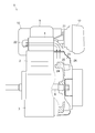
図面を参照して、単気筒空冷エンジン(以下、単にエンジン)1の構成について説明する。図1に示すように、エンジン1は、上部にシリンダブロック2、下部にクランクケース3を備える。シリンダブロック2の上部はシリンダヘッド4によって覆われ、さらに、シリンダヘッド4の上部をボンネット5で覆うことにより、弁腕室を構成している。シリンダブロック2の中央上下方向に単一のシリンダ6が形成され、シリンダ6内にピストン7が収納される。クランクケース3内には、クランク軸8が軸支され、ピストン7とクランク軸8とがコンロッド9により連結されている。
ボンネット5の一側部には排気マフラー10が設けられ、排気マフラー10の反対側の側部には燃料タンク11が設けられる。言い換えれば、排気マフラー10と燃料タンク11とでボンネット5を挟むように配置されている。ボンネット5の残る二方向の側面には、エアクリーナ12と酸化触媒13がそれぞれ設けられている。エアクリーナ12は吸気側、酸化触媒13は排気側に設けられる。
図2に示すように、シリンダヘッド4の吸気側側面には吸気マニホールド21が、排気側側面には排気マニホールド22がそれぞれ取り外し可能に取り付けられている。吸気マニホールド21は、同じく吸気側に設けられるエアクリーナ12と接続され、エアクリーナ12から送られてくる空気を吸入する。排気マニホールド22は、同じく排気側に設けられる酸化触媒13と排気マフラー10に接続され、燃焼後の排気ガスを酸化触媒13と排気マフラー10に送る。
エアクリーナ12の下方には、冷却ファン23が設けられる。冷却ファン23は、クランクケース3から延出されるクランク軸8の端部に固定されたフライホイール24と、フライホイール24の外周部に固定される複数のフィン25とによって構成され、ファンケース26によって覆われている。そして、ファンケース26内に吸い込んだ空気を冷却風としてシリンダブロック2やシリンダヘッド4などに送り、これらの部材を冷却風で冷却するように構成される。以上のように、エンジン1は、単気筒の空冷エンジンとして構成されている。
図1に示すように、クランクケース3内には、燃料調量用のガバナ31が設けられ、その上部に燃料噴射ポンプ32が設けられる。クランク軸8上にギア33が設けられている。ギア33はカム軸34上に設けられるカムギア35と歯合する。またカム軸34上にはポンプ駆動カム36が設けられている。クランク軸8のギア33からカム軸34のカムギア35に動力が伝達されることによりポンプ駆動カム36が回転駆動される。ポンプ駆動カム36によって燃料噴射ポンプ32のプランジャを往復動させることで、燃料タンク11から燃料を吸入するとともに、高圧管を介して燃料噴射ノズル37に所定のタイミングで所定量の燃料を供給する。燃料噴射ポンプ32による燃料供給量は、ガバナ31のコントロールレバー38を回動することにより、プランジャのストロークを変更することで調節可能である。
ガバナ31には、カム軸34上に設けられたギアを介して動力が伝えられる。ガバナ31の一端には回転数が大きくなると開くガバナウェイトが設けられ、他端にはガバナレバーを介してコントロールレバー38が係合されている。ガバナ31と燃料噴射ポンプ32との間に適宜のガバナ機構が設けられ、そのガバナ機構を介して連動連結することで、エンジン1のクランク軸8の回転がガバナ機構に回転力として伝えられ、回転数の上昇とともに遠心力によりコントロールレバー38を回動して燃料噴射量を増加させる。このようにして、エンジン1の回転数に応じた燃料噴射量の調節を行うことで、エンジン1を設定回転数で運転可能としている。
図3及び図4に示すように、シリンダヘッド4には、中央部に吸気ポート41に連通する吸気バルブ用挿入孔42と、排気ポート43に連通する排気バルブ用挿入孔44と、がそれぞれ上下方向に設けられる。吸気ポート41には、吸気マニホールド21を介してエアクリーナ12が接続される。排気ポート43には、排気マニホールド22を介して酸化触媒13及び排気マフラー10が接続される。吸気バルブ用挿入孔42には、吸気バルブ45が挿通され、排気バルブ用挿入孔44には、排気バルブ46が挿通されている。吸気バルブ45及び排気バルブ46の上端は、シリンダヘッド4の上方に貫通してボンネット5の弁腕室内に突出して配置される。吸気バルブ45及び排気バルブ46は、適宜の動弁機構を介して、燃料噴射ポンプ32の燃料噴射タイミング(燃焼のタイミング)に合わせて上下動し、開閉するように構成される。
図4に示すように、シリンダヘッド4において、冷却性能を向上することを目的として、構造上の強度を確保できる範囲内で、冷却ファン23からの送風が当たる領域(冷却を必要とする領域であり、例えば、図示中央における吸気ポート41と排気ポート43を隔てる壁部)の薄肉化が施されている。このように、シリンダヘッド4の壁部を局所的に薄くすることで、空冷による冷却性能を向上することができる。シリンダヘッド4の薄肉化とは、例えば、図4に示すように、吸気ポート41と排気ポート43を隔てる壁部の上下方向の厚みAを吸気バルブ45及び排気バルブ46の弁座の上下方向の厚みBよりも小さくすることを示す。この場合、吸気バルブ45及び排気バルブ46の弁座の厚みBは強度的な観点から薄肉化を施すことは適当ではないため、壁部の厚みAを小さくしている。また、このように吸気ポート41と排気ポート43との壁部を薄肉化していることで、高温の排気ガスが流通する排気ポート43の壁部と冷却風通路の接触面積を大きくしている。これにより、排気ポート43側を効果的に冷却することができ、エンジン1の冷却性能を向上することができる。一方で、シリンダヘッド4に薄肉化を施すことで、従来構造のように内壁にEGR通路を設けることが難しくなっている。言い換えれば、壁部にEGR通路を設けるために、薄肉化した部位に肉盛りすることが必要となり、冷却性能を向上するという趣旨に反することとなってしまう。
次に、本エンジン1に設けられる排気再循環用のEGR配管の構成について説明する。図5に示すように、EGR配管50は、シリンダヘッド4の外部に設けられている。具体的には、EGR配管50は、吸気マニホールド21の上部と排気マニホールド22の上部を繋ぐようにシリンダヘッド4の上方に延出して設けられている。そして、排気マニホールド22から吸気マニホールド21に向かう際に、ボンネット5と排気マフラー10との間を通過するように配置されている。
ボンネット5と排気マフラー10の間には、ボンネット5及び排気マフラー10よりも低い位置に隙間が形成されている。EGR配管50をその空間を利用して配置することで、高温のEGRガスが流通するEGR配管50に触れてしまう可能性が低くなる。また、エンジン1において存在している隙間を有効的に利用することでエンジン1の体格を大きくすることがなく、エンジン1の設置性を低下させることがない。
さらに、EGR配管50を排気マフラー10の近傍(ボンネット5と排気マフラー10の間の空間において、排気マフラー10に寄せた位置)に配置することで、エンジン1の使用に伴い高温となる排気マフラー10の熱をEGR配管50に伝達することができ、EGR配管50内を流通するEGRガスが冷えにくくなる。以上のように、EGR配管50をボンネット5と排気マフラー10の間に形成される空間内に、これらの高さを超えないように配置することで、排気再循環を効率良く行うことができるとともに、EGR配管50の取り回しも良くすることができる。
図5及び図6に示すように、EGR配管50は、その中途部において吸気側配管51と排気側配管52の二つに分割するとともに、分割部分を接続部材53によって接続した分割構造を有する。吸気側配管51は、吸気マニホールド21の上部に溶接等により固定される。排気側配管52は、排気マニホールド22の上部に溶接等により固定される。つまり、EGR配管50は、吸気側と排気側に分割可能な構造を有している。
接続部材53は、EGR配管50の分割部分を連結するための部材であり、吸気側配管51の端部に設けられるナット53aと、排気側配管52の端部に設けられるナット53bとにより構成されている。ナット53a・53bの締結を解除することでEGR配管50を中途部で分割することが可能である。
このように、配管自体を回転させる必要のないユニオンナットを用いて締結する方法の他、両配管の連結部分にフランジを設けてボルト・ナットを用いて締結する方法等を利用したものである。これらに限定されることはなく、クイックジョイント等、取り外し可能なものであれば、一般的に配管を連結する際に用いる方法を採用することもできる。
接続部材53の取り外し作業を考慮すると、接続部材53をEGR配管50の直線部分に配置することが好ましい。例えば、本実施形態のEGR配管50は、吸気マニホールド21の上部から上方に向けて延出され、排気マニホールド22側に向けて曲げられた後に、ボンネット5と排気マフラー10の間を抜け、排気マニホールド22の上部に向けて下方に曲げられることで、吸気マニホールド21の上部と排気マニホールド22の上部とを接続している。この場合、ボンネット5と排気マフラー10の間のストレート部分50aに接続部材53を配置することが好ましい。なお、接続部材53を設ける場所は、ストレート部分50aに限らず、EGR配管50の曲げ部分以外に存在する直線部分であれば良い。
図6に示すように、シリンダヘッド4のメンテナンスを行う際は、EGR配管50の接続部材53を取り外し、吸気マニホールド21と排気マニホールド22をシリンダヘッド4から取り外すことで、容易に分解することができる。このように、EGR配管50を分割構造とすることで、外部EGR構造を有するエンジン1のメンテナンス性を低下させることがない。なお、ボンネット5と排気マフラー10の間にEGR配管50を配置しているため、ボンネット5単独のメンテナンスを実施する際は、EGR配管50を取り外す必要がない。さらに、EGR配管50を分割構造としていることで、機関を組み立てる際の作業も容易となり、組立性を低下させることもない。
本発明は、単気筒空冷エンジンに利用可能である。
1:エンジン(単気筒空冷エンジン)、4:シリンダヘッド、5:ボンネット、10:排気マフラー、21:吸気マニホールド、22:排気マニホールド、50:EGR配管、53:接続部材
Claims (3)
- 排気側から吸気側に排気ガスを循環する排気再循環用のEGR配管をシリンダヘッドの外部に設けるとともに、
前記EGR配管を前記シリンダヘッドの上部を覆うボンネットと、前記シリンダヘッドの側部に設けられる排気マフラーとの間に配置したことを特徴とする単気筒空冷エンジン。 - 前記EGR配管は、吸気側に接続される吸気側配管と排気側に接続される排気側配管とに分割され、前記吸気側配管と前記排気側配管とを取外し可能な接続部材によって接続することで構成されることを特徴とする請求項1に記載の単気筒空冷エンジン。
- 前記EGR配管は、前記シリンダヘッドの吸気側と排気側の間に直線部分を有するとともに、前記直線部分に前記接続部材を配置したことを特徴とする請求項2に記載の単気筒空冷エンジン。
Priority Applications (1)
| Application Number | Priority Date | Filing Date | Title |
|---|---|---|---|
| CN201880004781.8A CN110325726A (zh) | 2017-03-01 | 2018-02-28 | 单缸风冷发动机 |
Applications Claiming Priority (2)
| Application Number | Priority Date | Filing Date | Title |
|---|---|---|---|
| JP2017038748A JP2018145818A (ja) | 2017-03-01 | 2017-03-01 | 単気筒空冷エンジン |
| JP2017-038748 | 2017-03-01 |
Publications (1)
| Publication Number | Publication Date |
|---|---|
| WO2018159672A1 true WO2018159672A1 (ja) | 2018-09-07 |
Family
ID=63371059
Family Applications (1)
| Application Number | Title | Priority Date | Filing Date |
|---|---|---|---|
| PCT/JP2018/007495 Ceased WO2018159672A1 (ja) | 2017-03-01 | 2018-02-28 | 単気筒空冷エンジン |
Country Status (3)
| Country | Link |
|---|---|
| JP (1) | JP2018145818A (ja) |
| CN (1) | CN110325726A (ja) |
| WO (1) | WO2018159672A1 (ja) |
Citations (2)
| Publication number | Priority date | Publication date | Assignee | Title |
|---|---|---|---|---|
| JPH07103083A (ja) * | 1993-10-01 | 1995-04-18 | Toyota Motor Corp | 排気ガス再循環装置 |
| JP2008163750A (ja) * | 2006-12-26 | 2008-07-17 | Yanmar Co Ltd | エンジン |
Family Cites Families (2)
| Publication number | Priority date | Publication date | Assignee | Title |
|---|---|---|---|---|
| JP6192576B2 (ja) * | 2014-03-20 | 2017-09-06 | ヤンマー株式会社 | エンジン装置 |
| CN106907274A (zh) * | 2017-04-20 | 2017-06-30 | 安徽江淮汽车集团股份有限公司 | 一种发动机减排系统 |
-
2017
- 2017-03-01 JP JP2017038748A patent/JP2018145818A/ja active Pending
-
2018
- 2018-02-28 WO PCT/JP2018/007495 patent/WO2018159672A1/ja not_active Ceased
- 2018-02-28 CN CN201880004781.8A patent/CN110325726A/zh active Pending
Patent Citations (2)
| Publication number | Priority date | Publication date | Assignee | Title |
|---|---|---|---|---|
| JPH07103083A (ja) * | 1993-10-01 | 1995-04-18 | Toyota Motor Corp | 排気ガス再循環装置 |
| JP2008163750A (ja) * | 2006-12-26 | 2008-07-17 | Yanmar Co Ltd | エンジン |
Also Published As
| Publication number | Publication date |
|---|---|
| JP2018145818A (ja) | 2018-09-20 |
| CN110325726A (zh) | 2019-10-11 |
Similar Documents
| Publication | Publication Date | Title |
|---|---|---|
| JP5362369B2 (ja) | エンジン装置 | |
| US8627659B2 (en) | Engine assembly including exhaust port separation for turbine feed | |
| JP6476796B2 (ja) | 多気筒エンジンの冷却用オイル通路構造 | |
| CN103133074A (zh) | 立式ohv式空冷发动机 | |
| WO2013145513A1 (ja) | エンジン | |
| US12221938B2 (en) | Engine cylinder block structure | |
| CN115443377B (zh) | 内燃机 | |
| JP2018145818A (ja) | 単気筒空冷エンジン | |
| JP2008297919A (ja) | 吸気装置 | |
| WO2013111648A1 (ja) | 掃気行程を有する6サイクルエンジン | |
| WO2012122820A1 (zh) | 垂直轴汽油机缸头总成及其汽油机 | |
| JP6005379B2 (ja) | エンジン | |
| CN111742132B (zh) | 船舶用柴油发动机的扫气整流构造 | |
| WO2011134380A1 (zh) | 汽缸头气门布置结构及包括其的风冷柴油机 | |
| JP5624012B2 (ja) | Ohv式エンジン | |
| JP7303024B2 (ja) | 船舶用内燃機関 | |
| JP2012154195A (ja) | リターン通路の構造 | |
| JPH0623542B2 (ja) | V型多気筒機関におけるインタクーラ配置構造 | |
| JP5624850B2 (ja) | エンジン | |
| CN201705487U (zh) | 风冷柴油机汽缸头气门布置结构 | |
| JP4087580B2 (ja) | 気化器の取付構造 | |
| JP2517063Y2 (ja) | 自動車におけるv型内燃機関の吸気マニホールド冷却装置 | |
| JP7230678B2 (ja) | 車両用エンジン | |
| JP6344404B2 (ja) | エンジンの吸気冷却装置 | |
| JPS588910Y2 (ja) | 過給式多気筒内燃機関 |
Legal Events
| Date | Code | Title | Description |
|---|---|---|---|
| 121 | Ep: the epo has been informed by wipo that ep was designated in this application |
Ref document number: 18761558 Country of ref document: EP Kind code of ref document: A1 |
|
| NENP | Non-entry into the national phase |
Ref country code: DE |
|
| 122 | Ep: pct application non-entry in european phase |
Ref document number: 18761558 Country of ref document: EP Kind code of ref document: A1 |