WO2018159198A1 - 二次電池 - Google Patents
二次電池 Download PDFInfo
- Publication number
- WO2018159198A1 WO2018159198A1 PCT/JP2018/003098 JP2018003098W WO2018159198A1 WO 2018159198 A1 WO2018159198 A1 WO 2018159198A1 JP 2018003098 W JP2018003098 W JP 2018003098W WO 2018159198 A1 WO2018159198 A1 WO 2018159198A1
- Authority
- WO
- WIPO (PCT)
- Prior art keywords
- negative electrode
- current collector
- plate
- electrode group
- foil exposed
- Prior art date
- Legal status (The legal status is an assumption and is not a legal conclusion. Google has not performed a legal analysis and makes no representation as to the accuracy of the status listed.)
- Ceased
Links
Images





Classifications
-
- H—ELECTRICITY
- H01—ELECTRIC ELEMENTS
- H01M—PROCESSES OR MEANS, e.g. BATTERIES, FOR THE DIRECT CONVERSION OF CHEMICAL ENERGY INTO ELECTRICAL ENERGY
- H01M50/00—Constructional details or processes of manufacture of the non-active parts of electrochemical cells other than fuel cells, e.g. hybrid cells
- H01M50/50—Current conducting connections for cells or batteries
- H01M50/531—Electrode connections inside a battery casing
-
- H—ELECTRICITY
- H01—ELECTRIC ELEMENTS
- H01M—PROCESSES OR MEANS, e.g. BATTERIES, FOR THE DIRECT CONVERSION OF CHEMICAL ENERGY INTO ELECTRICAL ENERGY
- H01M10/00—Secondary cells; Manufacture thereof
- H01M10/04—Construction or manufacture in general
-
- H—ELECTRICITY
- H01—ELECTRIC ELEMENTS
- H01M—PROCESSES OR MEANS, e.g. BATTERIES, FOR THE DIRECT CONVERSION OF CHEMICAL ENERGY INTO ELECTRICAL ENERGY
- H01M4/00—Electrodes
- H01M4/02—Electrodes composed of, or comprising, active material
- H01M4/64—Carriers or collectors
- H01M4/66—Selection of materials
-
- Y—GENERAL TAGGING OF NEW TECHNOLOGICAL DEVELOPMENTS; GENERAL TAGGING OF CROSS-SECTIONAL TECHNOLOGIES SPANNING OVER SEVERAL SECTIONS OF THE IPC; TECHNICAL SUBJECTS COVERED BY FORMER USPC CROSS-REFERENCE ART COLLECTIONS [XRACs] AND DIGESTS
- Y02—TECHNOLOGIES OR APPLICATIONS FOR MITIGATION OR ADAPTATION AGAINST CLIMATE CHANGE
- Y02E—REDUCTION OF GREENHOUSE GAS [GHG] EMISSIONS, RELATED TO ENERGY GENERATION, TRANSMISSION OR DISTRIBUTION
- Y02E60/00—Enabling technologies; Technologies with a potential or indirect contribution to GHG emissions mitigation
- Y02E60/10—Energy storage using batteries
-
- Y—GENERAL TAGGING OF NEW TECHNOLOGICAL DEVELOPMENTS; GENERAL TAGGING OF CROSS-SECTIONAL TECHNOLOGIES SPANNING OVER SEVERAL SECTIONS OF THE IPC; TECHNICAL SUBJECTS COVERED BY FORMER USPC CROSS-REFERENCE ART COLLECTIONS [XRACs] AND DIGESTS
- Y02—TECHNOLOGIES OR APPLICATIONS FOR MITIGATION OR ADAPTATION AGAINST CLIMATE CHANGE
- Y02P—CLIMATE CHANGE MITIGATION TECHNOLOGIES IN THE PRODUCTION OR PROCESSING OF GOODS
- Y02P70/00—Climate change mitigation technologies in the production process for final industrial or consumer products
- Y02P70/50—Manufacturing or production processes characterised by the final manufactured product
Definitions
- the present invention relates to a secondary battery.
- lithium ion secondary batteries Since lithium ion secondary batteries have higher energy density than other secondary batteries, they are mainly used in portable devices such as digital cameras, notebook computers and mobile phones. In recent years, research and development of large-sized lithium ion secondary batteries for the purpose of electric vehicles and power storage have been actively conducted in order to cope with environmental problems. In particular, in the automobile industry, the development of electric vehicles using a motor as a power source and hybrid electric vehicles using both an internal combustion engine and a motor are underway, some of which have already been put into practical use. Yes.
- the uncoated portions of the positive electrode and the negative electrode protrude from both ends of the electrode group in which the electrodes are laminated,
- the protruding uncoated part By connecting the protruding uncoated part to the electrode terminal or current collector, a simple configuration is possible, the current path to the electrode terminal or current collector is shortened, the connection resistance is reduced, and the output is high.
- the uncoated portion and the current collector are electrically connected by ultrasonic welding or resistance welding.
- metal foreign matter may be generated and enter the electrode group during the welding process of joining the current collector and the uncoated part of the electrode group.
- the metal foreign matter that has entered the electrode group enters between the positive electrode and the negative electrode in the electrode group, comes into contact with the positive electrode, is ionized, passes through the separator disposed between the positive electrode and the negative electrode, and is negative. Deposited at the electrode. When deposits deposited on the negative electrode accumulate and come into contact with the positive electrode, an internal short circuit occurs. Thus, when the positive electrode and the negative electrode are partially short-circuited, a necessary voltage cannot be obtained and the battery performance is deteriorated.
- an uncoated part is formed by providing a hole in an uncoated part and inserting a holding member therethrough and joining the uncoated part and the current collector in a sandwiched state.
- a structure is disclosed in which the holding member inserted through the metal member prevents the entry of metal foreign matter generated in the welding process into the electrode group.
- Patent Document 1 there is a risk of occurrence of foreign matter in the electrode foil when a hole is provided in an uncoated part. Further, the structure and the manufacturing method are complicated.
- the present invention makes the structure and manufacturing method simpler than that of Patent Document 1, and prevents the entry of metallic foreign matter generated in the welding process in which the current collector and the uncoated part of the winding group are joined into the electrode group.
- An object of the present invention is to provide a secondary battery that realizes a current collecting structure with high resistance to dust generation.
- a wound electrode group in which a mixture layer is applied and an electrode having a metal foil exposed part on one end side is laminated, and a current collector plate connected to the metal foil exposed part by welding is provided.
- the exposed portion of the metal foil between the mixture layer stack portion of the wound electrode group and the welded portion of the current collector plate is provided with a recess toward the winding center direction of the wound electrode group. ing.
- the metal foil gap in the exposed portion of the metal foil is narrowed, and it is possible to prevent the entry of metal foreign matter generated in the welding process for joining the current collector and the exposed metal foil portion of the electrode group into the electrode group.
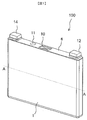
- FIG. 1 is an external perspective view of Embodiment 1 illustrating the present invention as a square secondary battery.
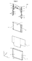
- FIG. 2 is an exploded perspective view of the secondary battery illustrated in FIG. 1.
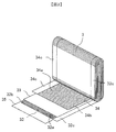
- FIG. 3 is an exploded perspective view illustrating a state where a part of the wound electrode group illustrated in FIG. 2 is developed. Sectional drawing of the junction part of the negative electrode foil exposure part of the winding electrode group illustrated in FIG. The disassembled perspective view at the time of ultrasonic bonding of the negative electrode foil exposure part of the wound electrode group illustrated in FIG. Sectional drawing of the junction part of the negative electrode foil exposure part at the time of ultrasonic joining illustrated in FIG. Sectional drawing of the junction part of the negative electrode foil exposure part of the winding electrode group of Embodiment 1.
- FIG. FIG. 1 is an external perspective view of Embodiment 1 illustrating the present invention as a square secondary battery.
- FIG. 2 is an exploded perspective view of the secondary battery illustrated in FIG. 1.
- FIG. 3 is an exploded perspective view illustrating a state where
- FIG. 6 is an external perspective view of a protective metal plate according to a second embodiment. Sectional drawing of the junction part of the negative electrode foil exposure part of the winding electrode group of Embodiment 2.
- FIG. FIG. 9 is an exploded perspective view of the negative electrode foil exposed portion of the wound electrode group according to the second embodiment when ultrasonic bonding is performed. Sectional drawing of the junction part of the negative electrode foil exposure part of the winding electrode group of Embodiment 3.
- FIG. FIG. 9 is an exploded perspective view of the negative electrode foil exposed portion of the wound electrode group according to the third embodiment when ultrasonic bonding is performed. Sectional drawing of the junction part of the negative electrode foil exposure part of the winding electrode group of Embodiment 4.
- FIG. 1 is an external perspective view of a prismatic secondary battery.
- the prismatic secondary battery 100 includes a battery can 1 and a battery lid 6.
- the battery can 1 and the battery lid 6 are made of a metal material such as an aluminum alloy, for example, and are formed by performing deep drawing and pressing.
- the wound electrode group 3 (see FIG. 2) is built in the battery can 1, and the opening 1 a of the battery can 1 is sealed by the battery lid 6.
- the battery lid 6 has a substantially rectangular flat plate shape, and is welded so as to close the opening 1 a of the battery can 1 to seal the battery can 1.
- the battery cover 6 is provided with a positive external terminal 14 and a negative external terminal 12 fixed to the battery cover 6 by an insulating member 5 by insert molding.
- the wound electrode group 3 is charged via the positive external terminal 14 and the negative external terminal 12, and power is supplied to the external load.
- the battery cover 6 is integrally provided with a gas discharge valve 10, and when the pressure in the battery container rises, the gas discharge valve 10 opens to discharge gas from the inside, and the pressure in the battery container is reduced. Thereby, the safety of the prismatic secondary battery 100 is ensured.
- FIG. 2 is an exploded perspective view of the prismatic secondary battery.
- the battery can 1 of the rectangular secondary battery 100 includes a rectangular bottom surface 1d, a wide surface 1b rising from a pair of long sides of the bottom surface 1d, a narrow surface 1c rising from a pair of short sides of the bottom surface 1d, and the wide surface 1b. And an opening 1a opened upward at the upper end of the narrow surface 1c.
- a wound electrode group 3 is accommodated in the battery can 1 via an insulating protective film 2.
- the wound electrode group 3 is formed by winding a strip-like electrode into a flat shape, and is formed continuously between a pair of curved portions facing each other and having a semicircular cross section, and the pair of curved portions. And a flat portion.
- the wound electrode group 3 is inserted into the battery can 1 from one curved portion side so that the winding axis direction is along the lateral width direction of the battery can 1 and faces the bottom surface 1d, and the other curved portion side is an opening. It is arranged on the 1a side.
- the positive electrode foil exposed portion 34 c of the wound electrode group 3 is electrically connected to the positive external terminal 14 provided on the battery lid 6 via the positive current collector plate 44.
- the negative electrode foil exposed portion 32 c of the wound electrode group 3 is electrically connected to the negative electrode external terminal 12 provided on the battery lid 6 via the negative electrode current collector plate 24.
- a gasket 5 and an insulating plate 7 are provided on the battery lid 6. It has been. Moreover, after injecting electrolyte solution into the battery can 1 from the liquid injection port 9, a liquid injection stopper 11 is joined to the battery lid 6 by laser welding to seal the liquid injection port 9, and the rectangular secondary battery 100 is sealed. To do.
- examples of the material for forming the positive electrode current collector plate 44 include an aluminum alloy
- examples of the material for forming the negative electrode current collector plate 24 include a copper alloy
- examples of the material for forming the gasket 5 include resin materials having insulation properties such as polybutylene terephthalate, polyphenylene sulfide, and perfluoroalkoxy fluororesin.
- the battery lid 6 is provided with a liquid injection port 9 for injecting an electrolytic solution into the battery container.
- the liquid injection port 9 is an injection stopper after the electrolytic solution is injected into the battery container. 11 is sealed.
- a non-aqueous electrolytic solution in which a lithium salt such as lithium hexafluorophosphate (LiPF 6 ) is dissolved in a carbonic acid ester-based organic solvent such as ethylene carbonate is used. Can be applied.
- the positive external terminal 14 and the negative external terminal 12 have a weld joint that is welded to a bus bar or the like.
- the welded joint has a flat surface disposed above the gasket 5 and parallel to the outer surface of the battery lid 6, and a bus bar or the like is brought into contact with the flat surface to be welded. .
- the positive electrode current collector plate 44 and the negative electrode current collector plate 24 extend toward the bottom surface along the wide surface of the battery can 1, and face the positive electrode foil exposed portion 34 c and the negative electrode foil exposed portion 32 c of the wound electrode group 3.
- the positive electrode side connection end portion 42 and the negative electrode side connection end portion 22 which are connected in a state of being overlapped with each other.
- the insulating protective film 2 is wound around the wound electrode group 3 with the direction along the flat plane of the wound electrode group 3 and the direction orthogonal to the wound axis direction of the wound electrode group 3 as the central axis direction.
- the insulating protective film 2 is made of, for example, a single sheet made of synthetic resin such as PP (polypropylene) or a plurality of film members, and is parallel to the flat surface of the wound electrode group 3 and orthogonal to the winding axis direction. It has a length that can be wound around the direction as the winding center.
- FIG. 3 is an exploded perspective view showing a state in which a part of the wound electrode group is developed.
- the wound electrode group 3 is configured by winding in a flat shape via separators 33 and 35 between the negative electrode 32 and the positive electrode 34.
- the outermost electrode is the negative electrode 32
- separators 33 and 35 are wound further outside.
- the separators 33 and 35 have a role of insulating between the positive electrode 34 and the negative electrode 32.
- the portion where the negative electrode mixture layer 32b of the negative electrode 32 is applied is larger in the width direction than the portion of the positive electrode 34 where the positive electrode mixture layer 34b is applied, so that the portion where the positive electrode mixture layer 34b is applied is
- the negative electrode mixture layer 32b is always sandwiched between the coated portions.
- the positive foil exposed portion 34c and the negative foil exposed portion 32c are bundled at a plane portion and connected by welding or the like.
- the separators 33 and 35 are wider than the portion where the negative electrode mixture layer 32b is applied in the width direction, but are wound at positions where the metal foil surface at the end is exposed at the positive electrode foil exposed portion 34c and the negative electrode foil exposed portion 32c. Therefore, it does not hinder bundle welding.
- the positive electrode 34 has a positive electrode active material mixture on both surfaces of a positive electrode foil 34a that is a positive electrode current collector, and a positive electrode foil in which the positive electrode active material mixture is not applied to one end in the width direction of the positive electrode foil 34a.
- An exposed portion 34c is provided.
- the negative electrode 32 has a negative electrode active material mixture on both sides of a negative electrode foil 32a, which is a negative electrode current collector, and the negative electrode foil in which the negative electrode active material mixture is not applied to the other end in the width direction of the negative electrode foil 32a.
- An exposed portion 32c is provided.
- the positive electrode foil exposed portion 34c and the negative electrode foil exposed portion 32c are regions where the metal surface of the electrode foil is exposed, and are wound so as to be disposed on one side and the other side in the winding axis direction.
- negative electrode 32 10 parts by weight of polyvinylidene fluoride (hereinafter referred to as PVDF) is added as a binder to 100 parts by weight of amorphous carbon powder as a negative electrode active material, and N as a dispersion solvent.
- NMP kneading methylpyrrolidone
- amorphous carbon is used as the negative electrode active material, but the present invention is not limited to this.
- Natural graphite capable of inserting and removing lithium ions and various artificial graphite materials Carbonaceous materials such as coke, compounds such as Si and Sn (for example, SiO, TiSi 2 etc.), or composite materials thereof may be used. It is not limited.
- the positive electrode 34 10 parts by weight of flaky graphite as a conductive material and 10 parts by weight of PVDF as a binder are added to 100 parts by weight of lithium manganate (chemical formula LiMn 2 O 4 ) as a positive electrode active material.
- a positive electrode mixture was prepared by adding and kneading NMP as a dispersion solvent. This positive electrode mixture was applied to both surfaces of an aluminum foil (positive electrode foil) having a thickness of 20 ⁇ m leaving a welded portion (positive electrode uncoated portion). Thereafter, a positive electrode 31 having a thickness of 90 ⁇ m in the thickness of the positive electrode active material coating portion not including an aluminum foil was obtained through drying, pressing, and cutting processes.
- lithium manganate is used as the positive electrode active material
- other lithium manganate having a spinel crystal structure or a lithium manganese composite oxide or layered in which a part is substituted or doped with a metal element A lithium cobalt oxide or lithium titanate having a crystal structure, or a lithium-metal composite oxide obtained by substituting or doping a part thereof with a metal element may be used.
- PVDF polytetrafluoroethylene
- polyethylene polyethylene
- polystyrene polybutadiene
- butyl rubber nitrile rubber
- Polymers such as styrene butadiene rubber, polysulfide rubber, nitrocellulose, cyanoethyl cellulose, various latexes, acrylonitrile, vinyl fluoride, vinylidene fluoride, propylene fluoride, chloroprene fluoride, acrylic resins, and mixtures thereof.
- PTFE polytetrafluoroethylene
- polyethylene polystyrene
- polybutadiene butyl rubber
- nitrile rubber Polymers such as styrene butadiene rubber, polysulfide rubber, nitrocellulose, cyanoethyl cellulose, various latexes, acrylonitrile, vinyl fluoride, vinylidene fluoride, propylene fluoride, chloroprene fluoride, acrylic resins, and mixture
- a positive-side protective metal plate is disposed in front of the positive-side connection end 42 of the positive-electrode current collector plate 44 in the z direction via a positive-electrode metal foil exposed portion 34 c of the wound electrode group 3.
- 40 is arranged.
- a negative electrode side protective metal plate 30 is disposed in front of the negative electrode side connection end portion 22 of the negative electrode current collector plate 24 in the z direction via the negative electrode metal foil exposed portion 32 c of the wound electrode group 3.
- the positive electrode metal foil exposed portion 34 c of the wound electrode group 3 is disposed between the positive electrode current collector plate 44 and the positive electrode side protective metal plate 40, and is sandwiched between the positive electrode current collector plate 44 and the positive electrode side protective metal plate 40.
- joining is performed by welding such as ultrasonic welding or resistance welding.
- the negative electrode metal foil exposed portion 32 c of the wound electrode group 3 is disposed between the negative electrode current collector plate 24 and the negative electrode side protective metal plate 30, and the negative electrode current collector plate 24 and the negative electrode side protective metal plate 30.
- welding such as ultrasonic welding or resistance welding.
- FIG. 4 is a cross-sectional view of the wound electrode group 3, the negative electrode current collector plate 24, and the negative electrode side protective metal plate 40 having a conventional structure, for explaining the principle of the present invention.
- the principle of dust generation will be described with reference to FIG.
- FIG. 4 is a cross-sectional view of the negative electrode foil exposed portion 32c in a state where the negative electrode current collector plate 24 and the negative electrode side protective metal plate 30 are joined as described above.
- metal foreign matter is generated by rubbing between the negative electrode foil exposed portions 32c.
- the generated metal foreign matter reaches the mixture layer portion 201a through the foil gap of the negative electrode foil exposed portion 32c.
- the separator 33 may pass therethrough and an internal short circuit may occur between the positive electrode 34 and the negative electrode 32.
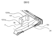
- FIG. 5 is an external perspective view when the negative electrode foil exposed portion 32 c of the wound electrode group 3 is sandwiched between the negative electrode current collector plate 24 and the negative electrode side protective metal plate 30 and is ultrasonically welded. Since the structure on the positive electrode side is the same as that shown in the figure, in this embodiment, the negative electrode side will be described as a representative. As shown in FIG. 5, the positioning jig 101 is devised in order to provide the metal foil narrowing portion 32 d which is a characteristic portion of the present invention. The narrowed portion 32d will be described below including the creation process.
- the negative electrode foil exposed portion 32 c is placed on the negative electrode current collector plate 24.
- the negative electrode side protection metal plate 30 is pressed by the positioning jig 101 having an open joint, and the negative electrode metal foil exposed portion 32 c is clamped between the protection metal plate 30 and the negative electrode current collector plate 24.
- the positioning jig 101 is provided with a convex portion 101a from the base portion 101b toward the center of the wound group of the wound electrode group 3. Further, the convex portion 101 a of the positioning jig 101 is disposed so as to be positioned between the mixture layer stacking portion and the negative electrode side protection metal plate 30.
- FIG. 6 shows the position of the negative electrode foil exposed portion 32c in a state in which the constricted portion 32d is provided in which the negative electrode foil exposed portion 32c is sandwiched between the negative protective metal plate 30 and the negative current collector plate 24 using the positioning jig 101. It is sectional drawing of a laminated part. As shown in FIG. 6, the convex portion 101a provided on the positioning jig 101 is pressed against the negative foil exposed portion 32c. Therefore, the narrowed portion 32 d is provided in the negative electrode foil exposed portion 32.
- the anvil of the ultrasonic welder is brought into contact with the negative electrode current collector plate 24, and the ultrasonic horn is brought into contact with the negative electrode side protection metal plate 30 from the opening of the positioning jig 101 to perform ultrasonic bonding. .
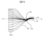
- FIG. 7 is a cross-sectional view of the laminated portion of the negative electrode foil exposed portion 32 c after performing ultrasonic welding using the positioning jig 101.
- the negative electrode foil exposed portion 32 c between the mixture layer laminated portion of the wound electrode group 3 and the welded portion of the current collector plate 24 ultrasonically welded in the present manufacturing example A recess 32e is provided in the wound electrode group 3 toward the winding center direction. At this time, the foil gap of the negative electrode foil exposed portion 32c becomes narrow and the narrowed portion 32d remains.
- the metal foreign matter generated during welding does not reach the mixture layer 201a by the positioning jig 101 during welding, but the constricted portion 32d has a concave shape even when the electrolyte is added.
- the path for the metallic foreign object to reach the mixture layer portion 201d becomes as if it were a maze. Therefore, the distance until the metal foreign matter generated in the vicinity of the negative electrode current collector plate 24 reaches the mixture layer portion 201a becomes long, and the metal foreign matter does not easily reach the mixture layer portion 201a. Thereby, it can suppress that the metal foreign material which generate
- the depth of the concave shape is effective regardless of the depth, but it is sufficiently effective if the metal foil on the surface of the concave portion 32e is recessed from the surface on which the foil of the negative electrode current collector plate 24 is mounted. (See BB in FIG. 7).
- the concave shape is provided toward the negative electrode current collector plate 24 side.
- the present invention can naturally be applied to the positive electrode current collector plate 44 side. By providing the concave portions on both the positive electrode side and the negative electrode side, it becomes more difficult for the metal foreign matter to enter the mixture layer portion 201a.
- the secondary battery 100 has a positive electrode 34 coated with a mixture layer and having a metal foil exposed portion on one end side, a negative electrode 32, one side surface on which each side edge of each of the separators 33 and 35 is laminated, and a positive electrode 34, the negative electrode 32, and the wound electrode group 3 having the other side surface where the other side edges of the separators 33 and 34 are laminated, the negative electrode current collector plate 24 connected to the negative electrode foil exposed portion 32c, and the negative electrode current collector A negative electrode foil between the mixed electrode layer stack portion of the wound electrode group 3 and the welded portion of the negative electrode current collector plate 24 is provided with a negative electrode side protective metal plate 30 sandwiching the negative electrode foil exposed portion 32c with the plate 24.
- the exposed portion 32 c is provided with a recess that extends in the winding center direction of the wound electrode group 3.
- a mixture layer (32b, 34b) is applied, and an electrode (32, 34) having a metal foil exposed portion (32c, 34c) on one end side is provided.
- the metal foil exposed portion (32c, 34c) between the laminated portion (32b, 34b) and the welded portion of the current collector plate (24, 44) has a concave portion directed toward the center of winding of the wound electrode group (3). Is provided.
- ultrasonic welding is used for welding.
- the present invention is effective even in the case of resistance welding, but the effect of suppressing metal foreign matter intrusion can be increased by applying to ultrasonic welding where metal foils are more likely to rub.
- Embodiment 2 will be described.
- the difference between the present embodiment and the first embodiment is that the protective metal plate 30 of the first embodiment has a flat plate structure with a size covering the joint, whereas the protective metal plate 50 of the present embodiment is on one side.
- the point which has the convex part which protrudes differs.
- FIG. 8 is a perspective view of the protective metal plate 50 according to the second embodiment.
- the protective metal plate 50 is composed of two parts, a flat part 50b facing the current collector and a convex part 50a protruding from the flat part 50b.
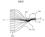
- FIG. 9 is a cross-sectional view of the laminated portion of the negative electrode foil exposed portion 32c where the convex portions 50a of the protective metal plate 50 are arranged so as to protrude with respect to the winding center direction.
- the negative electrode foil exposed portion 32 c of the wound electrode group 3 is disposed between the negative electrode current collector plate 24 and the protective metal plate 50, and is sandwiched between the negative electrode current collector plate 24 and the protective metal plate 50 to be a constricted portion. It joins in the state provided with 32d.
- the convex part of the protective metal plate 50 has a size that does not cause an internal short circuit and the foil gap of the negative electrode foil exposed part 32 c is smaller than the thickness of the separator 33.
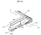
- FIG. 10 is an exploded perspective view of the negative electrode foil exposed portion 32 c, the protective metal plate 50 and the negative electrode current collector plate 24.
- the width W1 of the protective metal plate 50 is larger than the width W2 of the joint portion 202a with the negative electrode foil exposed portion 32c, and the mixture layer stack portion of the wound electrode group 3 and the negative electrode
- the width of the concave portion provided in the negative electrode foil exposed portion 32c between the current collector plate 24 and the welded portion and extending toward the winding center of the wound electrode group 3 is increased.
- the width W1 of the protective metal plate 50 is, for example, the width of the flat portion of the wound electrode group 3 (the width between the pair of curved portions of the wound electrode group 3), the effect becomes greater as described above. .
- size of the convex part of the convex part 50a of the metal plate 50 for protection if a recessed part is dented rather than the surface which mounts the foil of the negative electrode current collecting plate 24 like Example 1, it is fully effective. Therefore, if the convex portion of the protective metal plate 50 reaches the position on the surface of the negative electrode current collector plate 24 (position BB in FIG. 9), it is sufficiently effective against foreign matter intrusion.
- the same effect as in the first embodiment is obtained. Furthermore, since the protective metal plate 50 having a convex portion protruding in the winding center direction is arranged and bonded so as to be pressed against the negative electrode foil exposed portion 32c, the mixture layer laminated portion of the wound electrode group 3 and A structure in which the concave portion facing the winding center direction of the wound electrode group 3 provided in the negative electrode foil exposed portion between the welded portion of the negative electrode current collector plate is not deformed by an external force such as a subsequent step of injecting an electrolytic solution or vibration. It becomes.
- the metal foil exposed portions (32c, 34c) are sandwiched between the current collector plates (24, 44) and the plate metal member (50), and the plate metal
- the member (50) has a structure in which a convex portion (50a) directed toward the winding center of the wound electrode group (3) is provided and is in contact with the concave portion (32d).
- the width W1 of the protective metal plate 50 is equal to the width W2 of the joint portion.
- the tension of the curved portion of the wound electrode group 3 is large, and the curved portion.
- the width W1 of the protective metal plate 50 is, for example, the width of the flat portion of the wound electrode group 3 (the width between a pair of curved portions of the wound electrode group 3). If it is, it will become possible to suppress the metal foreign material penetration
- Embodiment 3 will be described.
- the present embodiment is different from the second embodiment in that instead of the protective metal plate of the first embodiment, the current collector plate is provided with a protruding portion that protrudes in the winding center direction.
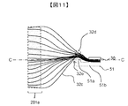
- FIG. 11 shows the third embodiment of the present invention and is the same cross-sectional schematic diagram as FIG.
- the negative electrode foil exposed portion 32 c of the wound electrode group 3 is disposed between the negative electrode current collector plate 51 and the negative electrode side protective metal plate 30 and is sandwiched between the current collector plate 51 and the negative electrode side protective metal plate 30. Bonding is performed in a state where the narrowed portion 32d is formed.
- the negative electrode current collector plate 51 having a convex portion 51e that protrudes with respect to the negative electrode foil exposed portion 32c presses the negative electrode foil exposed portion 32c. Since the negative electrode foil exposed portion 32c between the mixture layer portion 201a of the wound electrode group 3 and the welded portion of the negative electrode current collector plate 51 is disposed, the negative electrode current collector plate 51 is disposed. On one surface, a recess 32e is provided in the winding electrode group 3 toward the winding center direction. At this time, the foil gap of the negative electrode foil exposed portion 32c is narrowed to provide the narrowed portion 32d.
- the convex portion 51 a of the negative electrode current collector plate 51 has such a size that does not cause an internal short circuit and the foil gap of the negative electrode foil exposed portion 32 c is smaller than the thickness of the separator 33.
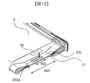
- FIG. 12 is an exploded perspective view of the negative electrode foil exposed portion 32 c, the negative electrode side protective metal plate 30, and the negative electrode current collector plate 51.
- the mixture layer stack of the wound electrode group 3 is larger as the width W3 of the convex portion 51a of the negative electrode current collector plate 51 is larger than the width W2 of the joint portion with the negative electrode foil exposed portion 32c.
- the width of the concave portion provided in the negative electrode foil exposed portion 32c between the portion and the welded portion of the negative electrode current collector plate toward the winding center direction of the wound electrode group 3 is increased.
- the width W3 of the convex part 51a of the current collector plate is, for example, the width of the flat part of the wound electrode group 3 (the width between the pair of curved parts of the wound electrode group 3), the mixture layer 201a The effect of suppressing the mixing of metallic foreign matter into the body is increased.
- size of the convex part of the convex part 51a of the current collecting plate 51 if a recessed part is dented rather than the surface which mounts the foil of the protective metal plate 30, it is sufficient as in Example 1. Therefore, if the convex portion 51a of the negative electrode current collector plate 51 reaches the position on the surface of the protective metal plate 30 (the position CC in FIG. 11), it is sufficiently effective against foreign matter intrusion.
- the convex part 51a is provided in the current collecting plate side with thick board thickness, it becomes a structure where a recessed part does not deform
- FIG. 1 is a structure where a recessed part does not deform
- the convex portion of the negative electrode current collector plate 51 can be formed by a press die, a casting die or the like.
- Embodiment 4 will be described.
- the difference between the present embodiment and the second embodiment is that, in addition to the protective metal plate of the second embodiment, a lower protective metal plate 52b having a convex portion is further provided between the current collector plate and the metal foil. is there.
- FIG. 13 shows the fourth embodiment of the present invention and is the same cross-sectional schematic diagram as FIG.
- the protective metal plate of the second embodiment is also disposed between the negative electrode foil exposed portion and the negative electrode current collector plate, and the negative electrode foil exposed portion includes the negative electrode current collector plate and the two protective metal plates 52a. , 52b.
- the other structure in Embodiment 4 is the same as that of Embodiment 2, and attaches
- the fourth embodiment includes an upper protective metal plate 52 a having a protrusion 52 c protruding from the base 52 d with respect to the negative electrode foil exposed portion 32 c and a protrusion 52 e protruding from the base 52 f. Since the lower protective metal plate 52b is disposed and bonded so that the convex portion is pressed against the negative electrode foil exposed portion 32c, the welded portion between the mixture layer portion 201a of the wound electrode group 3 and the negative electrode current collector plate 24 Two concave portions 32e1 and 32e2 are provided on both surfaces of the negative electrode foil exposed portion 32c between the first electrode 32 and the second electrode foil 3 toward the center of the wound electrode group 3.
- narrowed portions 32d1 and 32d2 are provided in which the foil gap of the negative electrode foil exposed portion 32c is narrowed.
- Embodiment 4 also has the same effect as Embodiments 2 and 3. Moreover, since the protective metal plates are arranged on both surfaces of the negative electrode foil exposed portion in the fourth embodiment, the foil gap in the negative electrode foil exposed portion can be made narrower than in the second and third embodiments, and is generated by welding. It can prevent more reliably that a metal foreign material approachs into the mixture layer. At this time, the convex portions of the protective metal plate arranged on both surfaces of the negative electrode foil exposed portion are arranged so as to be shifted between the mixture layer and the current collector plate even if they are arranged to face each other across the negative electrode foil exposed portion. May be. If the convex portions are shifted, the negative electrode foil exposed portion can be easily clamped between the current collector plate and the two protective metal plates, the work efficiency is improved, and the position of the protective metal plate is small. Become.
- the metal foil exposed portions (32c, 34c) are further connected between the current collecting plates (24, 44) and the plate-like metal member (52a). It has a plate-side plate-like metal member (52b), and the exposed metal foil portions (32c, 34c) are sandwiched between the plate-like metal member (52a) and the current-collection plate-side plate-like metal member (52b).
- the member (52b) has a structure in which convex portions (52c, 52e) directed toward the winding center direction of the wound electrode group (3) are provided and in contact with the concave portions (32d1, 32d2).
- the convex portion (52c) of the plate-like metal member (52a) and the convex portion (52e) of the current collector plate-side metal member (52b) are arranged so as to be shifted from each other.
- Embodiment 5 ⁇ Embodiment 5 >> Subsequently, Embodiment 5 will be described.
- This embodiment is different from the second embodiment in that in addition to the protective metal plate of the second embodiment, a current collecting plate 51 having a convex portion is further provided.
- FIG. 14 shows the fifth embodiment of the present invention and is the same cross-sectional schematic diagram as FIG.
- the other structure in Embodiment 5 is the same as that of Embodiment 2, and attaches
- the negative electrode foil exposed portion is joined in a state of being sandwiched between the same protective metal plate as in Embodiment 2 and the same negative current collector as in Embodiment 3.
- the same effects as in the fourth embodiment are obtained.
- the protective metal plate is only one surface in the fifth embodiment, it can be made cheaper than the third embodiment.
- the total thickness of the negative electrode foil exposed part to be joined and the protective metal plate does not increase, it can be joined easily. Even if the protective metal plate and the convex part of the current collector plate arranged across the negative electrode foil exposed part are opposed to each other across the negative electrode foil exposed part, they are shifted between the mixture layer and the current collector plate May be. If the convex portions are shifted, the negative electrode foil exposed portion can be easily clamped between the current collector plate and the two protective metal plates, the work efficiency is improved, and the position of the protective metal plate is small. Become.
- Embodiment 4 and Embodiment 5 although it was set as the structure where two recessed parts are provided, it is good also as a structure where two or more these recessed parts are provided. In that case, it becomes a structure which a metal foreign material cannot penetrate
- the configuration on the negative electrode side is shown, but this embodiment is not limited to the negative electrode side, and the same configuration as that on the negative electrode side is possible on the positive electrode side.
- the metal foil exposed portion between the mixture layer stack portion of the wound electrode group and the welded portion of the current collector plate showed only one configuration with a recess toward the winding center direction of the wound electrode group.
- the embodiment of the present invention is not limited to a single recess, and a plurality of recesses may be provided.
- the secondary battery was illustrated as a square lithium ion battery.
- the present invention can be applied to a secondary battery using a water-soluble electrolyte such as a cylindrical lithium ion battery, a nickel metal hydride battery, a nickel cadmium battery, or a lead storage battery.
- a water-soluble electrolyte such as a cylindrical lithium ion battery, a nickel metal hydride battery, a nickel cadmium battery, or a lead storage battery.
Landscapes
- Chemical & Material Sciences (AREA)
- Chemical Kinetics & Catalysis (AREA)
- Electrochemistry (AREA)
- General Chemical & Material Sciences (AREA)
- Engineering & Computer Science (AREA)
- Materials Engineering (AREA)
- Manufacturing & Machinery (AREA)
- Connection Of Batteries Or Terminals (AREA)
Abstract
捲回電極群の金属箔露出部を接合する際に発塵する金属異物が、捲回電極群の合剤層積層内部に進入して内部短絡が発生するのを抑制する。捲回電極群の金属箔露出部を接合する際に発塵する金属異物が、捲回電極群の合剤層積層部と接合部の間の金属箔隙間から合剤層積層内部に進入して内部短絡が発生するのを抑制することを課題とする。合剤層を塗布し、一端側に金属箔露出部を有する電極を捲回した捲回電極群と、前記金属箔露出部と溶接により接続される集電板と、を備えた二次電池において、捲回電極群の合剤層積層部と集電板の溶接部との間の金属箔露出部に、捲回電極群の捲回中心方向に向かう凹部が設けられることを特徴とする二次電池。
Description
本発明は二次電池に関する。
リチウムイオン二次電池は他の二次電池と比較してエネルギー密度が高いため、主にデジタルカメラやノート型パソコン、携帯電話などのポータブル機器に多く使用されている。また近年は環境問題に対応すべく、電気自動車用や電力貯蔵用を目的とする、大型のリチウムイオン二次電池の研究開発が活発に行われている。特に、自動車産業界においては、動力源としてモータを用いる方式の電気自動車や内燃機関とモータとの両方を用いるハイブリッド方式の電気自動車の開発が進められており、その一部はすでに実用化されている。
リチウムイオン二次電池においては、主に高出力を必要とする車載用等のリチウムイオン二次電池として、電極を積層させた電極群の両端に正極と負極それぞれの未塗工部を突出させ、突出させた未塗工部を電極端子又は集電体に接続することで、簡便な構成を可能にし、かつ電極端子や集電体に至る通電経路を短くし、接続抵抗を小さくして高出力が得られるように工夫したものが種々提案されている。未塗工部と集電体電気的な接続には、超音波溶接や抵抗溶接等により接合される。
リチウムイオン電池においては、集電体と電極群の未塗工部を接合する溶接工程で金属異物が発生し電極群内に進入する場合がある。電極群内に進入した金属異物は電極群内の正極電極と負極電極との間に入り込み、正極電極に接触してイオン化し、正極電極と負極電極の間に配置されたセパレータを透過して負極電極で析出する。負極電極に析出した析出物が堆積して正極側に接触すると内部短絡を生じる。このように正極電極と負極電極が部分的に短絡すると、必要な電圧が得られなくなり電池性能が低下する。
特許文献1に記載の電池においては、未塗工部に孔部を設け、そこに挟持部材を挿通させて未塗工部と集電体を挟持した状態で接合することで、未塗工部に挿通した挟持部材が溶接工程で発生する金属異物の電極群内への進入を防ぐ構造が開示されている。
特許文献1に記載の構造では、未塗工部に孔部を設ける際の電極箔の異物発生リスクがある。また、構造及び製造方法が複雑である。
本発明は、特許文献1に対して構造及び製造方法をより簡易にして、集電体と捲回群の未塗工部を接合する溶接工程で発生する金属異物の電極群内の進入を防止する、発塵耐性の高い集電構造を実現する二次電池を提供することを目的とする。
本発明では、合剤層を塗布し、一端側に金属箔露出部を有する電極を積層した捲回電極群と、前記金属箔露出部と溶接により接続される集電板と、を備えた二次電池において、前記捲回電極群の合剤層積層部と前記集電板の溶接部との間の金属箔露出部には、前記捲回電極群の捲回中心方向に向かう凹部が設けられている。
本発明によれば、金属箔露出部の金属箔隙間が狭くなり、集電体と電極群の金属箔露出部を接合する溶接工程で発生する金属異物の電極群内の進入を防止できる。
以下、本発明を実施するための実施形態について図面を用いて説明する。
≪実施形態1≫
図1は、角形二次電池の外観斜視図である。
図1は、角形二次電池の外観斜視図である。
角形二次電池100は、電池缶1および電池蓋6を備える。電池缶1と電池蓋6は、例えばアルミニウム合金などの金属材料からなり、深絞り加工及びプレス加工を施すことによって形成される。
電池缶1内には、捲回電極群3(図2を参照)が内蔵され、電池缶1の開口部1aが電池蓋6によって封口されている。電池蓋6は略矩形平板状であって、電池缶1の開口部1aを塞ぐように溶接されて電池缶1が封止されている。電池蓋6には、インサート成形により絶縁部材5によって電池蓋6に固定された正極外部端子14と、負極外部端子12が設けられている。正極外部端子14と負極外部端子12を介して捲回電極群3に充電され、また外部負荷に電力が供給される。電池蓋6には、ガス排出弁10が一体的に設けられ、電池容器内の圧力が上昇すると、ガス排出弁10が開いて内部からガスが排出され、電池容器内の圧力が低減される。これによって、角形二次電池100の安全性が確保される。
図2は、角形二次電池の分解斜視図である。
角形二次電池100の電池缶1は、長方形の底面1dと、底面1dの一対の長辺から立ち上がる幅広面1bと、底面1dの一対の短辺から立ち上がる幅狭面1cと、これら幅広面1b及び幅狭面1cの上端で上方に向かって開放された開口部1aとを有している。電池缶1内には、絶縁保護フィルム2を介して捲回電極群3が収容されている。
捲回電極群3は、帯状の電極が扁平形状に捲回されて構成されており、断面半円形状の互いに対向する一対の湾曲部と、これら一対の湾曲部の間に連続して形成される平面部とを有している。捲回電極群3は、捲回軸方向が電池缶1の横幅方向に沿うように、一方の湾曲部側から電池缶1内に挿入されて底面1dと対向し、他方の湾曲部側が開口部1a側に配置される。
捲回電極群3の正極箔露出部34cは、正極集電板44を介して電池蓋6に設けられた正極外部端子14と電気的に接続されている。また、捲回電極群3の負極箔露出部32cは、負極集電板24を介して電池蓋6に設けられた負極外部端子12と電気的に接続されている。これにより、正極集電板44および負極集電板24を介して捲回電極群3から外部負荷へ電力が供給され、正極集電板44および負極集電板24を介して捲回電極群3へ外部発電電力が供給され充電される。
正極集電板44と負極集電板24、及び、正極外部端子14と負極外部端子12を、それぞれ電池蓋6から電気的に絶縁するために、ガスケット5および絶縁板7が電池蓋6に設けられている。また、注液口9から電池缶1内に電解液を注入した後、電池蓋6に注液栓11をレーザ溶接により接合して注液口9を封止し、角形二次電池100を密閉する。
ここで、正極集電板44の形成素材としては、例えばアルミニウム合金が挙げられ、負極集電板24の形成素材としては、例えば銅合金が挙げられる。また、ガスケット5の形成素材としては、例えばポリブチレンテレフタレートやポリフェニレンサルファイド、ペルフルオロアルコキシフッ素樹脂等の絶縁性を有する樹脂材が挙げられる。
また、電池蓋6には、電池容器内に電解液を注入するための注液口9が穿設されており、この注液口9は、電解液を電池容器内に注入した後に注液栓11によって封止される。ここで、電池容器内に注入される電解液としては、例えばエチレンカーボネート等の炭酸エステル系の有機溶媒に6フッ化リン酸リチウム(LiPF6)等のリチウム塩が溶解された非水電解液を適用することができる。
正極外部端子14、負極外部端子12は、バスバー等に溶接接合される溶接接合部を有している。溶接接合部は、ガスケット5よりも上方で電池蓋6の外面と平行に配置される平坦面を有しており、かかる平坦面にバスバー等が接面されて溶接接合されるようになっている。
正極集電板44、負極集電板24は、電池缶1の幅広面に沿って底面側に向かって延出し、捲回電極群3の正極箔露出部34c、負極箔露出部32cに対向して重ね合わされた状態で接続される正極側接続端部42、負極側接続端部22を有している。
捲回電極群3の扁平面に沿う方向でかつ捲回電極群3の捲回軸方向に直交する方向を中心軸方向として捲回電極群3の周囲には絶縁保護フィルム2が巻き付けられている。絶縁保護フィルム2は、例えばPP(ポリプロピレン)などの合成樹脂製の一枚のシートまたは複数のフィルム部材からなり、捲回電極群3の扁平面と平行な方向でかつ捲回軸方向に直交する方向を巻き付け中心として巻き付けることができる長さを有している。
図3は、捲回電極群の一部を展開した状態を示す分解斜視図である。
捲回電極群3は、負極電極32と正極電極34の間にセパレータ33、35を介して扁平状に捲回することによって構成されている。捲回電極群3は、最外周の電極が負極電極32であり、さらにその外側にセパレータ33、35が捲回される。セパレータ33、35は、正極電極34と負極電極32との間を絶縁する役割を有している。負極電極32の負極合剤層32bが塗布された部分は、正極電極34の正極合剤層34bが塗布された部分よりも幅方向に大きく、これにより正極合剤層34bが塗布された部分は、必ず負極合剤層32bが塗布された部分に挟まれるように構成されている。正極箔露出部34c、負極箔露出部32cは、平面部分で束ねられて溶接等により接続される。尚、セパレータ33、35は幅方向で負極合剤層32bが塗布された部分よりも広いが、正極箔露出部34c、負極箔露出部32cで端部の金属箔面が露出する位置に捲回されるため、束ねて溶接する場合の支障にはならない。
正極電極34は、正極集電体である正極箔34aの両面に正極活物質合剤を有し、正極箔34aの幅方向一方側の端部には、正極活物質合剤を塗布しない正極箔露出部34cが設けられている。負極電極32は、負極集電体である負極箔32aの両面に負極活物質合剤を有し、負極箔32aの幅方向他方側の端部には、負極活物質合剤を塗布しない負極箔露出部32cが設けられている。正極箔露出部34cと負極箔露出部32cは、電極箔の金属面が露出した領域であり、捲回軸方向の一方側と他方側の位置に配置されるように捲回される。
負極電極32に関しては、負極活物質として非晶質炭素粉末100重量部に対して、結着剤として10重量部のポリフッ化ビニリデン(以下、PVDFという。)を添加し、これに分散溶媒としてN-メチルピロリドン(以下、NMPという。)を添加、混練した負極合剤を作製した。この負極合剤を厚さ10μmの銅箔(負極箔)の両面に溶接部(負極未塗工部)を残して塗布した。その後、乾燥、プレス、裁断工程を経て、銅箔を含まない負極活物質塗布部厚さ70μmの負極電極32を得た。
尚、本実施形態では、負極活物質に非晶質炭素を用いる場合について例示したが、これに限定されるものではなく、リチウムイオンを挿入、脱離可能な天然黒鉛や、人造の各種黒鉛材、コークスなどの炭素質材料やSiやSnなどの化合物(例えば、SiO、TiSi2等)、またはそれの複合材料でもよく、その粒子形状においても、鱗片状、球状、繊維状、塊状等、特に制限されるものではない。
正極電極34に関しては、正極活物質としてマンガン酸リチウム(化学式LiMn2O4)100重量部に対し、導電材として10重量部の鱗片状黒鉛と結着剤として10重量部のPVDFとを添加し、これに分散溶媒としてNMPを添加、混練した正極合剤を作製した。この正極合剤を厚さ20μmのアルミニウム箔(正極箔)の両面に溶接部(正極未塗工部)を残して塗布した。その後、乾燥、プレス、裁断工程を経て、アルミニウム箔を含まない正極活物質塗布部厚さ90μmの正極電極31を得た。
また、本実施形態では、正極活物質にマンガン酸リチウムを用いる場合について例示したが、スピネル結晶構造を有する他のマンガン酸リチウムや一部を金属元素で置換又はドープしたリチウムマンガン複合酸化物や層状結晶構造を有すコバルト酸リチウムやチタン酸リチウムやこれらの一部を金属元素で置換またはドープしたリチウム-金属複合酸化物を用いるようにしてもよい。
また、本実施形態では、正極電極34、負極電極32における塗工部の結着剤としてPVDFを用いる場合について例示したが、ポリテトラフルオロエチレン(PTFE)、ポリエチレン、ポリスチレン、ポリブタジエン、ブチルゴム、ニトリルゴム、スチレンブタジエンゴム、多硫化ゴム、ニトロセルロース、シアノエチルセルロース、各種ラテックス、アクリロニトリル、フッ化ビニル、フッ化ビニリデン、フッ化プロピレン、フッ化クロロプレン、アクリル系樹脂などの重合体およびこれらの混合体などを用いることができる。
図2に図示されるように、正極集電板44の正極側接続端部42のz方向の前方には、捲回電極群3の正極金属箔露出部34cを介して正極側保護用金属板40が配置されている。また、負極集電板24の負極側接続端部22のz方向の前方には、捲回電極群3の負極金属箔露出部32cを介して負極側保護用金属板30が配置されている。捲回電極群3の正極金属箔露出部34cは、正極集電板44と正極側保護用金属板40との間に配置され、正極集電板44と正極側保護用金属板40とにより挟圧された状態で、例えば、超音波溶接や抵抗溶接等の溶接により接合される。同様に、捲回電極群3の負極金属箔露出部32cは、負極集電板24と負極側保護用金属板30との間に配置され、負極集電板24と負極側保護用金属板30とにより挟圧された状態で、超音波溶接や抵抗溶接等の溶接により接合される。
図4は本発明の原理を説明するため、従来構造の捲回電極群3、負極集電板24、負極側保護用金属板40を切断した断面図である。図4を用いて発塵の原理について説明する。図4は負極箔露出部32cが負極集電板24と負極側保護用金属板30が上記のように接合された状態の断面図である。溶接により接合される際に、負極箔露出部32c同士の擦れにより金属異物が発塵する。発塵した金属異物は負極箔露出部32cの箔隙間を経由して合剤層部201aに到達する。また、接合時には合剤層部201aまで到達せずに負極箔露出部32cの箔隙間に存在する金属異物は、その後の電解液の注液工程などにより合剤層部201aに到達する。金属異物が合剤層部201aまで進入すると、溶解析出反応を起こし、セパレータ33を透過し正極電極34と負極電極32間で内部短絡が生じる可能性がある。
このように、金属異物に起因する捲回電極群3の内部短絡を防止するには、合剤層内部に金属異物が進入するのを抑制する必要がある。
続いて本発明の特徴点について説明する。図5は、捲回電極群3の負極箔露出部32cが、負極集電板24と負極側保護用金属板30とにより挟圧されて超音波溶接される時の外観斜視図である。なお、正極側の構造も本図と同様の構造となるため、本実施例では負極側を代表して説明する。図5に図示されるように、本発明の特徴部となる金属箔の狭窄部32dを設けるために、位置決め治具101を工夫している。その狭窄部32dを作成工程を含めて以下で説明する。
まずは負極集電板24に負極箔露出部32cを載せる。次に接合部が開口している位置決め冶具101で負極側保護用金属板30を押えて、負極金属箔露出部32cを保護用金属板30と負極集電板24とで挟圧する。このとき、位置決め冶具101は基部101bから捲回電極群3の捲回群中心方向に向かう凸部101aを設けてある。また、位置決め冶具101の凸部101aは、合剤層積層部と負極側保護用金属板30の間に位置するように配置する。
図6は、位置決め冶具101を用いて、負極箔露出部32cを負極側保護用金属板30と負極集電板24とで挟圧した狭窄部32dを設けた状態の、負極箔露出部32cの積層部の断面図である。図6に図示されるように、位置決め冶具101に設けられた凸部101aは負極箔露出部32cに押圧される。そのため、負極箔露出部32に狭窄部32dが設けられる。この状態で、超音波溶接機のアンビルを負極集電板24に当接させ、超音波ホーンを位置決め冶具101の開口部から負極側保護用金属板30に当接させ、超音波接合を実施する。
図7は位置決め冶具101を用いて超音波溶接を実施した後の負極箔露出部32cの積層部の断面図である。図7に図示されるように、本製造実施例で超音波溶接された、捲回電極群3の合剤層積層部と集電板24の溶接部との間の負極箔露出部32cには捲回電極群3の捲回中心方向に向かう凹部32eが設けられる。このとき、負極箔露出部32cの箔隙間は狭くなり狭窄部32dが残る。溶接時に発塵した金属異物は、当然溶接時には位置決め治具101によって合剤層部201aに到達しないようになるが、電解液を入れた際にもこの狭窄部32dが凹形状になっていることによって、金属異物が合剤層部201dに到達する経路があたかも迷路のようになる。そのため、負極集電板24の近傍で発生した金属異物が合剤層部201aに到達するまでの距離が長くなり、金属異物が合剤層部201aに到達しづらくなる。これにより、負極箔露出部32cが接合される際に発塵する金属異物が負極箔露出部32cの箔隙間を経由して合剤層部201aに到達するのを抑制することができる。なお、凹形状の程度はどの程度の深さであれ効果があるが、凹部32eの表面の金属箔が、負極集電板24の箔を搭載している面よりも凹んでいれば十分に効果がある(図7のB-B参照)。また、本実施形態では負極集電板24側に向かって凹形状を設ける構成としたが、当然負極側保護用金属板30側に凹形状となるように凹部32eを設けても効果がある。また、上述したように本発明を正極集電板44側に適用することも当然に可能である。正極側、負極側両方に凹部を設けることによって、より合剤層部201aに金属異物が侵入しにくくなる。
上記実施形態1によれば、下記の効果を奏する。
二次電池100は、合剤層を塗布し、一端側に金属箔露出部を有する正極電極34と負極電極32、セパレータ33、35それぞれの各一側縁が積層された一側面、および正極電極34と負極電極32、セパレータ33、34それぞれの他側縁が積層された他側面を有する捲回電極群3と、負極箔露出部32cと接続される負極集電板24と、前記負極集電板24とで負極箔露出部32cを挟持する負極側保護用金属板30を備え、前記捲回電極群3の合剤層積層部と前記負極集電板24の溶接部との間の負極箔露出部32cには、前記捲回電極群3の捲回中心方向に向かう凹部が設けられる。これにより、溶接で発生した金属異物が合剤層内部へ進入するのを防ぎ、金属異物による内部短絡を抑制することが可能となる。
上記の効果を実現するための具体的構造の一例としては、合剤層(32b、34b)を塗布し、一端側に金属箔露出部(32c、34c)を有する電極(32、34)を捲回した捲回電極群(3)と、金属箔露出部(32c、34c)と溶接により接続される集電板(24、44)と、を備え、捲回電極群(3)の合剤層積層部(32b、34b)と集電板(24、44)の溶接部との間の金属箔露出部(32c、34c)には、捲回電極群(3)の捲回中心方向に向かう凹部が設けられる構造である。
また、本実施形態では、溶接に超音波溶接を用いている。もちろん本発明は抵抗溶接の場合でも有効であるが、より金属箔同士が擦れやすい超音波溶接を行っているものに適用することで金属異物侵入抑制の効果が大きくなる。
≪実施形態2≫
続いて実施形態2について説明する。本実施形態が実施形態1と異なる点は、実施形態1の保護用金属板30は接合部を覆う大きさの平板構造であるのに対して、本実施形態の保護用金属板50は一面に突出する凸部を有する点が異なる。
続いて実施形態2について説明する。本実施形態が実施形態1と異なる点は、実施形態1の保護用金属板30は接合部を覆う大きさの平板構造であるのに対して、本実施形態の保護用金属板50は一面に突出する凸部を有する点が異なる。
図8は、実施形態2における保護用金属板50の斜視図である。図8に示す通り、保護用金属板50は集電板と対向する平坦部50bと、平坦部50bから突出する凸部50aの2つの部分からなる。
図9は、保護用金属板50の凸部50aが捲回中心方向に対して突出するように配置させて接合された、負極箔露出部32cの積層部の断面図である。捲回電極群3の負極箔露出部32cは、負極集電板24と保護用金属板50との間に配置され、負極集電板24と保護用金属板50とにより挟圧されて狭窄部32dが設けられた状態で接合される。
図9に図示されるように、本実施形態においては、負極箔露出部32cに対して突出する凸部32dを有する保護用金属板50が、その凸部32dが負極箔露出部32cに押圧するように配置されて接合されるため、捲回電極群3の合剤層部201aと負極集電板24の溶接部との間の負極箔露出部32cは、保護用金属板50が配置される一面に、前記捲回電極群3の捲回中心方向に向かう凹部32eが設けられる。このとき、負極箔露出部32cの箔隙間は狭くなり狭窄部32dが設けられることとなる。これにより、負極箔露出部32cが接合される際に発塵する金属異物が負極箔露出部32cの箔隙間を経由して合剤層部201aに進入するのを抑制することができる。このように、保護用金属板50の凸部は、内部短絡を引き起こさない、負極箔露出部32cの箔隙間がセパレータ33の厚みよりも小さくなるような大きさとすることが好ましい。
図10は、負極箔露出部32c、保護用金属板50と負極集電板24の分解斜視図である。図10に図示されるように、保護用金属板50の幅W1は、負極箔露出部32cとの接合部202aの幅W2よりも大きいほど、捲回電極群3の合剤層積層部と負極集電板24の溶接部との間の負極箔露出部32cに設けられる、捲回電極群3の捲回中心方向に向かう凹部の幅が大きくなる。これにより、負極箔露出部32cが接合される際に発塵する金属異物が負極箔露出部32cの箔隙間を経由して合剤層部201aに到達するのをより確実に抑制することができる。なお、保護用金属板50の幅W1が接合部の幅W2の幅であったとしても十分効果があることはいうまでもない。また、捲回電極群3の湾曲部の張力が大きいため、湾曲部には金属異物しづらい構造となっている。そのため、保護用金属板50の幅W1の幅はたとえば捲回電極群3の平坦部の幅(捲回電極群3の一対の湾曲部間の幅)であれば上述のとおりより効果が大きくなる。また、保護用金属板50の凸部50aの凸部の大きさについては、実施例1と同様、凹部が負極集電板24の箔を搭載している面よりも凹んでいれば十分に効果があるので、保護用金属板50の凸部は負極集電板24の表面の位置(図9のB-Bの位置)まで到達していれば十分に異物侵入に対して効果がある。
実施形態2においても、実施形態1と同様な効果を奏する。さらに、捲回中心方向に突出する凸部を有する保護用金属板50が、負極箔露出部32cに押圧するように配置されて接合されるため、捲回電極群3の合剤層積層部と負極集電板の溶接部との間の負極箔露出部に設けられる捲回電極群3の捲回中心方向に向かう凹部は、その後の電解液の注液工程や振動等の外力により変形しない構造となる。これにより、負極箔露出部の箔隙間を狭くした状態を、溶接後も確実に維持できるため、接合時には合剤層部まで到達せずに負極箔露出部の箔隙間に存在する金属異物が、その後の電解液の注液工程などにより合剤層積層部に進入することも確実に防止できる。
上記の効果を実現するための具体的構造の一例としては、金属箔露出部(32c、34c)が集電板(24、44)と板状金属部材(50)とによって挟持され、板状金属部材(50)は、捲回電極群(3)の捲回中心方向に向かう凸部(50a)が設けられ、凹部(32d)と当接している構造となっている。
また、保護用金属板50の幅W1が接合部の幅W2の幅であったとしても十分効果があることはいうまでもないが、捲回電極群3の湾曲部の張力が大きく、湾曲部には金属異物しづらい構造となっているため、保護用金属板50の幅W1の幅はたとえば捲回電極群3の平坦部の幅(捲回電極群3の一対の湾曲部間の幅)であればより合剤層部201aへの金属異物侵入を抑制することが可能となる。
≪実施形態3≫
続いて、実施形態3について説明する。本実施形態が実施形態2と異なる点は、実施形態1の保護用金属板に替えて、集電板に捲回中心方向に対して突出する凸部を設けた点である。
続いて、実施形態3について説明する。本実施形態が実施形態2と異なる点は、実施形態1の保護用金属板に替えて、集電板に捲回中心方向に対して突出する凸部を設けた点である。
図11は、本発明の実施形態3を示し、図9と同一断面模式図である。
捲回電極群3の負極箔露出部32cは、負極集電板51と負極側保護用金属板30との間に配置され、集電板51と負極側保護用金属板30とにより挟圧された狭窄部32dが形成された状態で接合される。
捲回電極群3の負極箔露出部32cは、負極集電板51と負極側保護用金属板30との間に配置され、集電板51と負極側保護用金属板30とにより挟圧された狭窄部32dが形成された状態で接合される。
図11に図示されるように、本実施形態においては、負極箔露出部32cに対して突出する凸部51eを有する負極集電板51が、その凸部51eが負極箔露出部32cに押圧するように配置されて接合されるため、捲回電極群3の合剤層部201aと負極集電板51の溶接部との間の負極箔露出部32cは、負極集電板51が配置される一面に、捲回電極群3の捲回中心方向に向かう凹部32eが設けられる。このとき、負極箔露出部32cの箔隙間は狭くなり狭窄部32dが設けられる。これにより、負極箔露出部32cが接合される際に発塵する金属異物が負極箔露出部32cの箔隙間を経由して合剤層部201aに到達するのを抑制することができる。このように、負極集電板51の凸部51aは、内部短絡を引き起こさない、負極箔露出部32cの箔隙間がセパレータ33の厚みよりも小さくなるような大きさとすることが好ましい。
図12は、負極箔露出部32c、負極側保護用金属板30と負極集電板51の分解斜視図である。図12に図示されるように、負極集電板51の凸部51aの幅W3は、負極箔露出部32cとの接合部の幅W2よりも大きいほど、捲回電極群3の合剤層積層部と負極集電板の溶接部との間の負極箔露出部32cに設けられる、捲回電極群3の捲回中心方向に向かう凹部の幅が大きくなる。これにより、負極箔露出部32cが接合される際に発塵する金属異物が負極箔露出部32cの箔隙間を経由して合剤層部201aに到達するのをより確実に抑制することができる。なお、集電板の凸部51aの幅W3が接合部の幅W2の幅であったとしても十分効果があることはいうまでもない。また、捲回電極群3の湾曲部の張力が大きいため、湾曲部には金属異物しづらい構造となっている。そのため、集電板の凸部51aの幅W3の幅はたとえば捲回電極群3の平坦部の幅(捲回電極群3の一対の湾曲部間の幅)であればより合剤層部201aへの金属異物混入抑制の効果が大きくなる。また、集電板51の凸部51aの凸部の大きさについては、実施例1と同様、凹部が保護用金属板30の箔を搭載している面よりも凹んでいれば十分に効果があるので、負極集電板51の凸部51aは保護用金属板30の表面の位置(図11のC-Cの位置)まで到達していれば十分に異物侵入に対して効果がある。なお、板厚の厚い集電板側に凸部51aを設けているため、実施形態2よりもより、凹部がその後の電解液の注液工程や振動等の外力により変形しない構造となる。
実施形態3においても、実施形態2と同様な効果を奏する。負極集電板51の凸部はプレス金型や鋳造型等により成型することができる。
≪実施形態4≫
続いて、実施形態4について説明する。本実施形態が実施形態2と異なる点は、実施形態2の保護用金属板に加えて、さらに凸部を有する下部保護用金属板52bを集電板と金属箔との間に設けた点である。
続いて、実施形態4について説明する。本実施形態が実施形態2と異なる点は、実施形態2の保護用金属板に加えて、さらに凸部を有する下部保護用金属板52bを集電板と金属箔との間に設けた点である。
図13は、本発明の実施形態4を示し、図11と同一断面模式図である。
実施形態4においては、実施形態2の保護用金属板は、負極箔露出部と負極集電板の間にも配置されており、負極箔露出部は、負極集電板と二つの保護用金属板52a、52bによって挟圧された状態で接合される。なお、実施形態4における他の構成は、実施形態2と同様であり、対応する部材に同一の符号を付して説明を省略する。
図13に図示されるように、実施形態4においては負極箔露出部32cに対して基部52dから突出する凸部52cを有する上部保護用金属板52aと、基部52fから突出する凸部52eを有する下部保護用金属板52bが、その凸部が負極箔露出部32cに押圧するように配置されて接合されるため、捲回電極群3の合剤層部201aと負極集電板24の溶接部との間の負極箔露出部32cの両面には、前記捲回電極群3の捲回中心方向に向かう2つの凹部32e1、32e2が設けられる。このとき、負極箔露出部32cの箔隙間が狭くなる狭窄部32d1、32d2が設けられる。この二つの狭窄部によって、実施形態1と比較して、負極集電板24の近傍で発生した金属異物が合剤層部201aに到達するまでの距離がより長くなり、金属異物が合剤層部201aに到達しづらくなる。そのため、より金属異物が合剤層部201aに到達する可能性が低くなり、内部短絡の可能性が低くなる。
実施形態4においても、実施形態2、3と同様な効果を奏する。しかも、実施形態4では保護用金属板が負極箔露出部の両面に配置されているので、実施形態2、3よりも負極箔露出部の箔隙間を一層狭くすることができ、溶接で発生した金属異物が合剤層内部へ進入するのをさらに確実に防ぐことができる。このとき、負極箔露出部の両面に配置する保護用金属板の凸部は、負極箔露出部を挟んで互いに対向して配置をしても、合剤層と集電板の間でずらして配置してもよい。凸部をずらして配置すると、負極箔露出部を、集電板と2つの保護用金属板によって挟圧することが容易となり、作業能率が良いものとなり、かつ、保護用金属板の位置ずれが少なくなる。
上記の効果を実現するための具体的構造の一例としては、金属箔露出部(32c、34c)は、集電板(24、44)と板状金属部材(52a)との間にさらに集電板側板状金属部材(52b)を有し、金属箔露出部(32c、34c)は板状金属部材(52a)及び集電板側板状金属部材(52b)で挟持され、集電板側板状金属部材(52b)は、捲回電極群(3)の捲回中心方向に向かう凸部(52c、52e)が設けられ、凹部(32d1、32d2)と当接している構造である。
また、本発明では、板状金属部材(52a)の凸部(52c)と、集電板側板状金属部材(52b)の凸部(52e)は互いにずれて配置される構造になっている。
≪実施形態5≫
続いて、実施形態5について説明する。本実施形態が実施形態2と異なる点は、実施形態2の保護用金属板に加えて、さらに凸部を有する集電板51設けた点である。図14は、本発明の実施形態5を示し、図13と同一断面模式図である。なお、実施形態5における他の構成は、実施形態2と同様であり、対応する部材に同一の符号を付して説明を省略する。
続いて、実施形態5について説明する。本実施形態が実施形態2と異なる点は、実施形態2の保護用金属板に加えて、さらに凸部を有する集電板51設けた点である。図14は、本発明の実施形態5を示し、図13と同一断面模式図である。なお、実施形態5における他の構成は、実施形態2と同様であり、対応する部材に同一の符号を付して説明を省略する。
実施形態5においては、負極箔露出部は、実施形態2と同じ保護用金属板と、実施形態3と同じ負極集電板によって挟圧された状態で接合される。
図14に図示されるように、実施形態5においては負極箔露出部32cに対して基部50bから突出する凸部50aを有する保護用金属板50と、基部51dから突出する凸部51aを有する負極集電板51が、それぞれ2つの凸部が負極箔露出部32cに押圧するように配置されて接合されるため、捲回電極群3の合剤層部201aと負極集電板51の溶接部との間の負極箔露出部32cの両面には、捲回電極群3の捲回中心方向に向かう凹部32d1、32d2が設けられる。このとき、負極箔露出部32cの箔隙間が狭くなる。
実施形態5においても、実施形態4と同様な効果を奏する。しかも、実施形態5では保護用金属板が一面のみであるため実施形態3よりも安価にすることができる。また、接合する負極箔露出部と保護用金属板の総厚みが大きくならないため、容易に接合することができる。負極箔露出部を挟んで配置する保護用金属板と集電板の凸部は、負極箔露出部を挟んで互いに対向して配置をしても、合剤層と集電板の間でずらして配置してもよい。凸部をずらして配置すると、負極箔露出部を、集電板と2つの保護用金属板によって挟圧することが容易となり、作業能率が良いものとなり、かつ、保護用金属板の位置ずれが少なくなる。
なお、実施形態4と実施形態5では凹部が2つ設けられる構造としたが、この凹部が2個以上設けられるような構造としてもよい。その場合には、より合剤層部201aに金属異物が侵入しにくい構造となる。
以上が本発明の内容になる。なお。上記実施形態における二次電池の構造は、単に一例として例示するものであり、適宜、変更して適用することが可能である。
上記実施形態では、負極側の構成のみを示したが、本実施形態は、負極側に限定するものではなく、正極側も負極側と同様の構成が可能である。また、捲回電極群の合剤層積層部と集電板の溶接部との間の金属箔露出部には、捲回電極群の捲回中心方向に向かう凹部が一つの構成のみ示したが、本発明の実施形態は一つの凹部に限定されるものではなく、複数の凹部を設ける構成としても良い。
上記実施形態では、二次電池を角形リチウムイオン電池として例示した。しかし、本発明は、円筒形リチウムイオン電池またはニッケル水素電池やニッケル・カドミウム電池、鉛蓄電池のように水溶性電解液を用いる二次電池にも適用が可能である
上記では、種々の実施の形態および変形例を説明したが、本発明はこれらの内容に限定されるものではない。上記各実施形態を組み合わせて適用することも可能であり、本発明の技術的思想の範囲内で考えられるその他の態様も本発明の範囲内に含まれる。
上記では、種々の実施の形態および変形例を説明したが、本発明はこれらの内容に限定されるものではない。上記各実施形態を組み合わせて適用することも可能であり、本発明の技術的思想の範囲内で考えられるその他の態様も本発明の範囲内に含まれる。
1 電池缶
1a 開口部
1b 幅広側面
1c 幅狭側面
1d 底面
2 絶縁保護フィルム
3 捲回電極群
5 ガスケット
6 電池蓋
7 絶縁板
9 注液口
10 ガス排出弁
11 注液栓
12 負極外部端子
14 正極外部端子
22 負極側接続端部
24 負極集電板
30 負極側保護用金属板
32 負極電極
32a 負極箔
32b 負極合剤層
32c 負極箔露出部
33 セパレータ
34 正極電極
34a 正極箔
34b 正極合剤層
34c 正極箔露出部
35 セパレータ
40 正極側保護用金属板
42 正極側接続端部
44 正極集電板
50 保護用金属板
51 負極集電板
52a 上部保護用金属板
52b 下部保護用金属板
100 角形二次電池
101 位置決め冶具
201a 合剤層部
202a 接合部
Claims (8)
- 合剤層を塗布し、一端側に金属箔露出部を有する電極を捲回した捲回電極群と、
前記金属箔露出部と溶接により接続される集電板と、を備えた二次電池において、
前記捲回電極群の合剤層積層部と前記集電板の溶接部との間の金属箔露出部には、前記捲回電極群の捲回中心方向に向かう凹部が設けられることを特徴とする二次電池。 - 請求項1に記載の二次電池において、前記溶接部は、超音波溶接部であることを特徴とする二次電池。
- 請求項1又は2に記載の二次電池において、前記金属箔露出部は、前記集電板と板状金属部材とによって挟持され、前記板状金属部材は、前記捲回電極群の捲回中心方向に向かう凸部が設けられ、前記凹部と当接していることを特徴とする二次電池。
- 請求項3に記載の二次電池において、前記金属箔露出部は、前記集電板と板状金属部材との間にさらに集電板側板状金属部材を有し、当該金属箔露出部は板状金属部材及び集電板側板状金属部材で挟持され、前記集電板側板状金属部材は、前記捲回電極群の捲回中心方向に向かう凸部が設けられ、前記凹部と当接していることを特徴とする二次電池。
- 請求項4に記載の二次電池において、前記板状金属部材の凸部と、前記集電板側板状金属部材の凸部は互いに対向して配置されることを特徴とする二次電池。
- 請求項4に記載の二次電池において、前記板状金属部材の凸部と、前記集電板側板状金属部材の凸部は互いにずれて配置されることを特徴とする二次電池。
- 請求項1乃至6のいずれかに記載の二次電池において、前記金属箔露出部は銅箔であり、前記電極は負極であることを特徴とする二次電池。
- 請求項1に記載の二次電池において、前記凹部は複数個設けられることを特徴とする二次電池。
Priority Applications (1)
| Application Number | Priority Date | Filing Date | Title |
|---|---|---|---|
| JP2019502523A JP6739615B2 (ja) | 2017-02-28 | 2018-01-31 | 二次電池 |
Applications Claiming Priority (2)
| Application Number | Priority Date | Filing Date | Title |
|---|---|---|---|
| JP2017035666 | 2017-02-28 | ||
| JP2017-035666 | 2017-02-28 |
Publications (1)
| Publication Number | Publication Date |
|---|---|
| WO2018159198A1 true WO2018159198A1 (ja) | 2018-09-07 |
Family
ID=63370049
Family Applications (1)
| Application Number | Title | Priority Date | Filing Date |
|---|---|---|---|
| PCT/JP2018/003098 Ceased WO2018159198A1 (ja) | 2017-02-28 | 2018-01-31 | 二次電池 |
Country Status (2)
| Country | Link |
|---|---|
| JP (1) | JP6739615B2 (ja) |
| WO (1) | WO2018159198A1 (ja) |
Cited By (1)
| Publication number | Priority date | Publication date | Assignee | Title |
|---|---|---|---|---|
| JPWO2023042467A1 (ja) * | 2021-09-16 | 2023-03-23 |
Citations (2)
| Publication number | Priority date | Publication date | Assignee | Title |
|---|---|---|---|---|
| JP2009259697A (ja) * | 2008-04-18 | 2009-11-05 | Toyota Motor Corp | 電池およびその製造方法 |
| JP2015037041A (ja) * | 2013-08-13 | 2015-02-23 | 株式会社リチウムエナジージャパン | 蓄電素子及びその製造方法 |
Family Cites Families (2)
| Publication number | Priority date | Publication date | Assignee | Title |
|---|---|---|---|---|
| JP2004071199A (ja) * | 2002-08-02 | 2004-03-04 | Japan Storage Battery Co Ltd | 電池 |
| JP5772364B2 (ja) * | 2011-08-04 | 2015-09-02 | トヨタ自動車株式会社 | 電池及び電池の製造方法 |
-
2018
- 2018-01-31 WO PCT/JP2018/003098 patent/WO2018159198A1/ja not_active Ceased
- 2018-01-31 JP JP2019502523A patent/JP6739615B2/ja active Active
Patent Citations (2)
| Publication number | Priority date | Publication date | Assignee | Title |
|---|---|---|---|---|
| JP2009259697A (ja) * | 2008-04-18 | 2009-11-05 | Toyota Motor Corp | 電池およびその製造方法 |
| JP2015037041A (ja) * | 2013-08-13 | 2015-02-23 | 株式会社リチウムエナジージャパン | 蓄電素子及びその製造方法 |
Cited By (2)
| Publication number | Priority date | Publication date | Assignee | Title |
|---|---|---|---|---|
| JPWO2023042467A1 (ja) * | 2021-09-16 | 2023-03-23 | ||
| JP7772808B2 (ja) | 2021-09-16 | 2025-11-18 | ビークルエナジージャパン株式会社 | 電池及び電池の製造方法 |
Also Published As
| Publication number | Publication date |
|---|---|
| JPWO2018159198A1 (ja) | 2019-06-27 |
| JP6739615B2 (ja) | 2020-08-12 |
Similar Documents
| Publication | Publication Date | Title |
|---|---|---|
| US8778530B2 (en) | Battery and battery pack using the same | |
| JP5417241B2 (ja) | 角形リチウムイオン二次電池および角形リチウムイオン二次電池の製造方法 | |
| US9583783B2 (en) | Prismatic secondary battery | |
| US20170125778A1 (en) | Rectangular Secondary Battery | |
| JP6363893B2 (ja) | 二次電池 | |
| KR102578860B1 (ko) | 이차 전지 | |
| WO2018020906A1 (ja) | 角形二次電池 | |
| JP5679272B2 (ja) | 電極端子付き電池蓋および密閉型電池 | |
| JP2018060599A (ja) | 角形二次電池 | |
| JP5633031B2 (ja) | 二次電池および二次電池の製造方法 | |
| CN109564998B (zh) | 方形二次电池 | |
| JP2018125110A (ja) | 二次電池 | |
| JP2015103420A (ja) | 角形二次電池 | |
| JP2016178053A (ja) | 角形二次電池 | |
| JP7117944B2 (ja) | 二次電池 | |
| JP6216203B2 (ja) | 捲回式二次電池 | |
| JP6739615B2 (ja) | 二次電池 | |
| JP2015118828A (ja) | 二次電池 | |
| JP2018056085A (ja) | 二次電池 | |
| JP6978500B2 (ja) | 二次電池 | |
| JP6382336B2 (ja) | 角形二次電池 | |
| KR102302054B1 (ko) | 전극 조립체 및 이를 포함하는 이차 전지 | |
| WO2017130702A1 (ja) | 角形二次電池 | |
| JP2011233257A (ja) | 二次電池 | |
| JP6504994B2 (ja) | 角形蓄電素子 |
Legal Events
| Date | Code | Title | Description |
|---|---|---|---|
| 121 | Ep: the epo has been informed by wipo that ep was designated in this application |
Ref document number: 18760419 Country of ref document: EP Kind code of ref document: A1 |
|
| ENP | Entry into the national phase |
Ref document number: 2019502523 Country of ref document: JP Kind code of ref document: A |
|
| NENP | Non-entry into the national phase |
Ref country code: DE |
|
| 122 | Ep: pct application non-entry in european phase |
Ref document number: 18760419 Country of ref document: EP Kind code of ref document: A1 |