WO2018155439A1 - レーダ装置 - Google Patents
レーダ装置 Download PDFInfo
- Publication number
- WO2018155439A1 WO2018155439A1 PCT/JP2018/006002 JP2018006002W WO2018155439A1 WO 2018155439 A1 WO2018155439 A1 WO 2018155439A1 JP 2018006002 W JP2018006002 W JP 2018006002W WO 2018155439 A1 WO2018155439 A1 WO 2018155439A1
- Authority
- WO
- WIPO (PCT)
- Prior art keywords
- transmission
- antenna elements
- vehicle
- mode
- radar apparatus
- Prior art date
Links
Images


Classifications
-
- G—PHYSICS
- G01—MEASURING; TESTING
- G01S—RADIO DIRECTION-FINDING; RADIO NAVIGATION; DETERMINING DISTANCE OR VELOCITY BY USE OF RADIO WAVES; LOCATING OR PRESENCE-DETECTING BY USE OF THE REFLECTION OR RERADIATION OF RADIO WAVES; ANALOGOUS ARRANGEMENTS USING OTHER WAVES
- G01S7/00—Details of systems according to groups G01S13/00, G01S15/00, G01S17/00
- G01S7/02—Details of systems according to groups G01S13/00, G01S15/00, G01S17/00 of systems according to group G01S13/00
-
- G—PHYSICS
- G01—MEASURING; TESTING
- G01S—RADIO DIRECTION-FINDING; RADIO NAVIGATION; DETERMINING DISTANCE OR VELOCITY BY USE OF RADIO WAVES; LOCATING OR PRESENCE-DETECTING BY USE OF THE REFLECTION OR RERADIATION OF RADIO WAVES; ANALOGOUS ARRANGEMENTS USING OTHER WAVES
- G01S13/00—Systems using the reflection or reradiation of radio waves, e.g. radar systems; Analogous systems using reflection or reradiation of waves whose nature or wavelength is irrelevant or unspecified
- G01S13/02—Systems using reflection of radio waves, e.g. primary radar systems; Analogous systems
- G01S13/06—Systems determining position data of a target
- G01S13/42—Simultaneous measurement of distance and other co-ordinates
- G01S13/426—Scanning radar, e.g. 3D radar
-
- G—PHYSICS
- G01—MEASURING; TESTING
- G01S—RADIO DIRECTION-FINDING; RADIO NAVIGATION; DETERMINING DISTANCE OR VELOCITY BY USE OF RADIO WAVES; LOCATING OR PRESENCE-DETECTING BY USE OF THE REFLECTION OR RERADIATION OF RADIO WAVES; ANALOGOUS ARRANGEMENTS USING OTHER WAVES
- G01S13/00—Systems using the reflection or reradiation of radio waves, e.g. radar systems; Analogous systems using reflection or reradiation of waves whose nature or wavelength is irrelevant or unspecified
- G01S13/87—Combinations of radar systems, e.g. primary radar and secondary radar
- G01S13/878—Combination of several spaced transmitters or receivers of known location for determining the position of a transponder or a reflector
-
- G—PHYSICS
- G01—MEASURING; TESTING
- G01S—RADIO DIRECTION-FINDING; RADIO NAVIGATION; DETERMINING DISTANCE OR VELOCITY BY USE OF RADIO WAVES; LOCATING OR PRESENCE-DETECTING BY USE OF THE REFLECTION OR RERADIATION OF RADIO WAVES; ANALOGOUS ARRANGEMENTS USING OTHER WAVES
- G01S13/00—Systems using the reflection or reradiation of radio waves, e.g. radar systems; Analogous systems using reflection or reradiation of waves whose nature or wavelength is irrelevant or unspecified
- G01S13/88—Radar or analogous systems specially adapted for specific applications
- G01S13/93—Radar or analogous systems specially adapted for specific applications for anti-collision purposes
- G01S13/931—Radar or analogous systems specially adapted for specific applications for anti-collision purposes of land vehicles
-
- G—PHYSICS
- G01—MEASURING; TESTING
- G01S—RADIO DIRECTION-FINDING; RADIO NAVIGATION; DETERMINING DISTANCE OR VELOCITY BY USE OF RADIO WAVES; LOCATING OR PRESENCE-DETECTING BY USE OF THE REFLECTION OR RERADIATION OF RADIO WAVES; ANALOGOUS ARRANGEMENTS USING OTHER WAVES
- G01S7/00—Details of systems according to groups G01S13/00, G01S15/00, G01S17/00
- G01S7/02—Details of systems according to groups G01S13/00, G01S15/00, G01S17/00 of systems according to group G01S13/00
- G01S7/03—Details of HF subsystems specially adapted therefor, e.g. common to transmitter and receiver
-
- G—PHYSICS
- G08—SIGNALLING
- G08G—TRAFFIC CONTROL SYSTEMS
- G08G1/00—Traffic control systems for road vehicles
- G08G1/16—Anti-collision systems
-
- G—PHYSICS
- G08—SIGNALLING
- G08G—TRAFFIC CONTROL SYSTEMS
- G08G1/00—Traffic control systems for road vehicles
- G08G1/16—Anti-collision systems
- G08G1/166—Anti-collision systems for active traffic, e.g. moving vehicles, pedestrians, bikes
-
- H—ELECTRICITY
- H01—ELECTRIC ELEMENTS
- H01Q—ANTENNAS, i.e. RADIO AERIALS
- H01Q1/00—Details of, or arrangements associated with, antennas
- H01Q1/27—Adaptation for use in or on movable bodies
- H01Q1/32—Adaptation for use in or on road or rail vehicles
- H01Q1/3208—Adaptation for use in or on road or rail vehicles characterised by the application wherein the antenna is used
- H01Q1/3233—Adaptation for use in or on road or rail vehicles characterised by the application wherein the antenna is used particular used as part of a sensor or in a security system, e.g. for automotive radar, navigation systems
-
- H—ELECTRICITY
- H01—ELECTRIC ELEMENTS
- H01Q—ANTENNAS, i.e. RADIO AERIALS
- H01Q21/00—Antenna arrays or systems
- H01Q21/06—Arrays of individually energised antenna units similarly polarised and spaced apart
-
- H—ELECTRICITY
- H01—ELECTRIC ELEMENTS
- H01Q—ANTENNAS, i.e. RADIO AERIALS
- H01Q21/00—Antenna arrays or systems
- H01Q21/06—Arrays of individually energised antenna units similarly polarised and spaced apart
- H01Q21/061—Two dimensional planar arrays
- H01Q21/065—Patch antenna array
-
- H—ELECTRICITY
- H01—ELECTRIC ELEMENTS
- H01Q—ANTENNAS, i.e. RADIO AERIALS
- H01Q21/00—Antenna arrays or systems
- H01Q21/24—Combinations of antenna units polarised in different directions for transmitting or receiving circularly and elliptically polarised waves or waves linearly polarised in any direction
-
- H—ELECTRICITY
- H01—ELECTRIC ELEMENTS
- H01Q—ANTENNAS, i.e. RADIO AERIALS
- H01Q21/00—Antenna arrays or systems
- H01Q21/29—Combinations of different interacting antenna units for giving a desired directional characteristic
-
- H—ELECTRICITY
- H01—ELECTRIC ELEMENTS
- H01Q—ANTENNAS, i.e. RADIO AERIALS
- H01Q3/00—Arrangements for changing or varying the orientation or the shape of the directional pattern of the waves radiated from an antenna or antenna system
- H01Q3/26—Arrangements for changing or varying the orientation or the shape of the directional pattern of the waves radiated from an antenna or antenna system varying the relative phase or relative amplitude of energisation between two or more active radiating elements; varying the distribution of energy across a radiating aperture
- H01Q3/30—Arrangements for changing or varying the orientation or the shape of the directional pattern of the waves radiated from an antenna or antenna system varying the relative phase or relative amplitude of energisation between two or more active radiating elements; varying the distribution of energy across a radiating aperture varying the relative phase between the radiating elements of an array
- H01Q3/34—Arrangements for changing or varying the orientation or the shape of the directional pattern of the waves radiated from an antenna or antenna system varying the relative phase or relative amplitude of energisation between two or more active radiating elements; varying the distribution of energy across a radiating aperture varying the relative phase between the radiating elements of an array by electrical means
- H01Q3/36—Arrangements for changing or varying the orientation or the shape of the directional pattern of the waves radiated from an antenna or antenna system varying the relative phase or relative amplitude of energisation between two or more active radiating elements; varying the distribution of energy across a radiating aperture varying the relative phase between the radiating elements of an array by electrical means with variable phase-shifters
-
- H—ELECTRICITY
- H04—ELECTRIC COMMUNICATION TECHNIQUE
- H04B—TRANSMISSION
- H04B7/00—Radio transmission systems, i.e. using radiation field
- H04B7/02—Diversity systems; Multi-antenna system, i.e. transmission or reception using multiple antennas
- H04B7/04—Diversity systems; Multi-antenna system, i.e. transmission or reception using multiple antennas using two or more spaced independent antennas
- H04B7/0413—MIMO systems
-
- G—PHYSICS
- G01—MEASURING; TESTING
- G01S—RADIO DIRECTION-FINDING; RADIO NAVIGATION; DETERMINING DISTANCE OR VELOCITY BY USE OF RADIO WAVES; LOCATING OR PRESENCE-DETECTING BY USE OF THE REFLECTION OR RERADIATION OF RADIO WAVES; ANALOGOUS ARRANGEMENTS USING OTHER WAVES
- G01S13/00—Systems using the reflection or reradiation of radio waves, e.g. radar systems; Analogous systems using reflection or reradiation of waves whose nature or wavelength is irrelevant or unspecified
- G01S13/02—Systems using reflection of radio waves, e.g. primary radar systems; Analogous systems
- G01S2013/0236—Special technical features
- G01S2013/0245—Radar with phased array antenna
- G01S2013/0254—Active array antenna
-
- G—PHYSICS
- G01—MEASURING; TESTING
- G01S—RADIO DIRECTION-FINDING; RADIO NAVIGATION; DETERMINING DISTANCE OR VELOCITY BY USE OF RADIO WAVES; LOCATING OR PRESENCE-DETECTING BY USE OF THE REFLECTION OR RERADIATION OF RADIO WAVES; ANALOGOUS ARRANGEMENTS USING OTHER WAVES
- G01S13/00—Systems using the reflection or reradiation of radio waves, e.g. radar systems; Analogous systems using reflection or reradiation of waves whose nature or wavelength is irrelevant or unspecified
- G01S13/88—Radar or analogous systems specially adapted for specific applications
- G01S13/93—Radar or analogous systems specially adapted for specific applications for anti-collision purposes
- G01S13/931—Radar or analogous systems specially adapted for specific applications for anti-collision purposes of land vehicles
- G01S2013/932—Radar or analogous systems specially adapted for specific applications for anti-collision purposes of land vehicles using own vehicle data, e.g. ground speed, steering wheel direction
-
- G—PHYSICS
- G01—MEASURING; TESTING
- G01S—RADIO DIRECTION-FINDING; RADIO NAVIGATION; DETERMINING DISTANCE OR VELOCITY BY USE OF RADIO WAVES; LOCATING OR PRESENCE-DETECTING BY USE OF THE REFLECTION OR RERADIATION OF RADIO WAVES; ANALOGOUS ARRANGEMENTS USING OTHER WAVES
- G01S13/00—Systems using the reflection or reradiation of radio waves, e.g. radar systems; Analogous systems using reflection or reradiation of waves whose nature or wavelength is irrelevant or unspecified
- G01S13/88—Radar or analogous systems specially adapted for specific applications
- G01S13/93—Radar or analogous systems specially adapted for specific applications for anti-collision purposes
- G01S13/931—Radar or analogous systems specially adapted for specific applications for anti-collision purposes of land vehicles
- G01S2013/9327—Sensor installation details
- G01S2013/93271—Sensor installation details in the front of the vehicles
-
- G—PHYSICS
- G01—MEASURING; TESTING
- G01S—RADIO DIRECTION-FINDING; RADIO NAVIGATION; DETERMINING DISTANCE OR VELOCITY BY USE OF RADIO WAVES; LOCATING OR PRESENCE-DETECTING BY USE OF THE REFLECTION OR RERADIATION OF RADIO WAVES; ANALOGOUS ARRANGEMENTS USING OTHER WAVES
- G01S13/00—Systems using the reflection or reradiation of radio waves, e.g. radar systems; Analogous systems using reflection or reradiation of waves whose nature or wavelength is irrelevant or unspecified
- G01S13/88—Radar or analogous systems specially adapted for specific applications
- G01S13/93—Radar or analogous systems specially adapted for specific applications for anti-collision purposes
- G01S13/931—Radar or analogous systems specially adapted for specific applications for anti-collision purposes of land vehicles
- G01S2013/9327—Sensor installation details
- G01S2013/93272—Sensor installation details in the back of the vehicles
-
- G—PHYSICS
- G01—MEASURING; TESTING
- G01S—RADIO DIRECTION-FINDING; RADIO NAVIGATION; DETERMINING DISTANCE OR VELOCITY BY USE OF RADIO WAVES; LOCATING OR PRESENCE-DETECTING BY USE OF THE REFLECTION OR RERADIATION OF RADIO WAVES; ANALOGOUS ARRANGEMENTS USING OTHER WAVES
- G01S13/00—Systems using the reflection or reradiation of radio waves, e.g. radar systems; Analogous systems using reflection or reradiation of waves whose nature or wavelength is irrelevant or unspecified
- G01S13/88—Radar or analogous systems specially adapted for specific applications
- G01S13/93—Radar or analogous systems specially adapted for specific applications for anti-collision purposes
- G01S13/931—Radar or analogous systems specially adapted for specific applications for anti-collision purposes of land vehicles
- G01S2013/9327—Sensor installation details
- G01S2013/93274—Sensor installation details on the side of the vehicles
Definitions
- the present disclosure relates to a radar apparatus.
- Patent Document 1 describes a radar apparatus that includes a transmission array antenna, a phase shifter provided for each unit antenna included in the transmission array antenna, and a reception array antenna and is mounted on a vehicle.
- the radar device operates in a backward approaching vehicle detection mode that detects a vehicle approaching from the rear when the vehicle is moving forward, and detects a vehicle that crosses the rear of the own vehicle when the vehicle is moving backward. Operate in mode.
- the detection area is set to a range suitable for each mode.
- the radar apparatus In the rear approaching vehicle detection mode, it is desirable to set the detection area in a range limited in the backward direction, and it is effective to control the directivity by controlling the phase shifter. On the other hand, in the crossing vehicle detection mode during reverse, it is desirable to set the detection area in a wide range of directions, and there is no need to control directivity.
- the radar apparatus When the radar apparatus is operated in the vehicle detection mode crossing when moving backward, one unit antenna is sufficient. As a result of detailed studies by the inventors, the radar apparatus has an excess of unit antennas when there is no need to control directivity, and therefore there is room for more effective use of the hardware configuration of the radar apparatus. A challenge has been found.
- a radar apparatus which includes a transmission array antenna, a phase shifter, a reception array antenna, a transmission control unit, and a signal processing unit.
- the transmission array antenna includes a plurality of transmission antenna elements and is configured to transmit a transmission wave.
- the phase shifter is provided in each of at least two of the transmission antenna elements, and is configured to change the phase of a transmission wave transmitted from the transmission antenna element provided with the phase shifter.
- the receiving array antenna includes a plurality of receiving antenna elements, and is configured to receive a reflected wave generated by reflecting a transmitted transmission wave by a target.
- the transmission control unit is configured to transmit the transmission wave via the transmission array antenna in one of the directivity control mode and the MIMO mode.
- the directivity control mode is an operation mode of the radar apparatus that controls the directivity of the transmission array antenna by controlling the phase shifter.
- the MIMO mode is an operation mode of the radar apparatus that selects at least two transmission antenna elements from the plurality of transmission antenna elements and transmits the transmission waves so as not to interfere with each other from the selected transmission antenna elements.
- the signal processing unit is configured to estimate the azimuth of the target from the reflected wave received by the receiving array antenna.
- a transmission wave is transmitted in one of the directivity control mode and the MIMO mode. Then, the reflected wave generated by reflecting the transmitted wave transmitted by the target is received by the receiving array antenna, and the direction of the target is estimated from the received reflected wave.
- the target existing in the specific direction can be accurately detected by operating the radar device in the directivity control mode.
- the radar device if you want to detect a target that exists in a wide range of directions, operate the radar device in MIMO mode to virtually increase the number of receiving antenna elements and improve the azimuth resolution of the radar device. Can do.
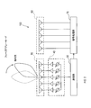
- the radar apparatus 100 is a millimeter wave radar including a transmission unit 30, a signal control unit 40, a transmission array antenna 50, a reception array antenna 60, and a signal processing unit 70.
- the transmission unit 30 includes a detection operation selection unit 31 and a transmission control unit 32.
- the detection operation selection unit 31 selects a suitable detection operation from a plurality of detection operations based on the measurement situation.
- the plurality of detection operations are operations in which the detection areas Ad are different from each other, and details will be described later.
- a suitable detection operation is selected from a plurality of detection operations based on the vehicle speed information of the host vehicle received from the vehicle speed sensor 11.
- the transmission control unit 32 operates the radar apparatus 100 in an operation mode according to the detection operation selected by the detection operation selection unit 31. That is, the transmission control unit 32 transmits a transmission wave from the transmission array antenna 50 in an operation mode corresponding to the selected detection operation. Specifically, the transmission control unit 32 generates a modulation signal, a transmission signal modulated according to the modulation signal, and a transmission control signal, and supplies the generated transmission signal and transmission control signal to the signal control unit 40.
- the modulation method is not particularly limited, and may be anything such as a two-frequency CW method, a multi-frequency CW method, or an FMCW method.
- the signal control unit 40 includes phase shifters 41a to 41e and amplifiers 42a to 42e corresponding to the phase shifters 41a to 41e.
- a set of each of the phase shifters 41a to 41e and each of the amplifiers 42a to 42e is provided on a transmission path between the transmission unit 30 and each of the transmission antenna elements 50a to 50e included in the transmission array antenna 50. It is connected.
- the phase shifters 41a to 41e control the phase of the transmission signal according to the transmission control signal.
- the amplifiers 42a to 42e control the amplitude of the transmission signal in accordance with the transmission control signal.
- the amplifiers 42a to 42e function as switches that cut off the transmission line by setting the amplification factor to zero.
- the transmission antenna elements 50a to 50e transmit transmission waves that are electromagnetic waves based on the transmission signals output from the amplifiers 42a to 42e, respectively. At this time, when there is an amplifier whose amplification factor is set to zero among the amplifiers 42a to 42e, no transmission signal is output from the amplifier whose amplification factor is set to zero, and transmission is performed from the corresponding transmission antenna element. Waves are not output.
- the signal processing unit 70 mixes the transmission signal supplied from the transmission unit 30 and the reception signal output from the reception array antenna 60 to generate a beat signal. Then, the signal processing unit 70 estimates the relative speed and position of the target P with respect to the radar apparatus 100 from the beat signal. Specifically, the signal processing unit 70 performs frequency analysis on the beat signal, detects the moving target P, and estimates the relative speed and distance of the detected target P with respect to the radar apparatus 100. Further, the signal processing unit 70 applies an azimuth expansion algorithm such as DBF, Capon, or MUSIC to the beat signal to estimate the arrival direction of the reflected wave, that is, the azimuth of the target P with respect to the radar apparatus 100. DBF is an abbreviation for Digital Beam Forming, and MUSIC is an abbreviation for Multiple Signal Classification.
- DBF is an abbreviation for Digital Beam Forming
- MUSIC is an abbreviation for Multiple Signal Classification.
- the signal processing unit 70 determines the possibility that the target P will collide with the host vehicle based on the estimated relative speed, distance, and direction of the target P. In order to alert the driver, an alarm is output from the alarm device 200.
- the functions of the transmission unit 30 and the signal processing unit 70 may be realized by the CPU executing a program stored in the memory, or by using hardware that combines a logic circuit, an analog circuit, and the like. May be. Moreover, you may implement
- the alarm device 200 is a door mirror, an indicator provided in the vehicle interior, a speaker in the vehicle interior, a display in the vehicle interior, or the like.
- the alarm device 200 blinks, outputs a warning sound or sound, or displays a warning in response to a warning output instruction from the signal processing unit 70.
- the operation mode of the radar apparatus 100 includes two modes, a phased array mode and a MIMO mode.
- MIMO is an abbreviation for Multi Input Multi Output.
- the phase of the transmission wave transmitted from each of the transmission antenna elements 50a to 50e is individually controlled by using the phase shifters 41a to 41e, so that the transmission wave transmitted from the transmission array antenna 50 is transmitted.
- This is an operation mode for controlling directivity. As shown in FIG. 2, when the radar apparatus 100 is operated in the phased array mode, a transmission wave having a directivity narrower than that of the MIMO mode is transmitted in a specific direction. In the present embodiment, the phased array mode corresponds to the directivity control mode.
- the MIMO mode is an operation mode in which at least two transmission antenna elements are selected from the transmission antenna elements 50a to 50e and transmission waves are transmitted from the selected transmission antenna elements.
- the transmission control unit 32 simultaneously transmits transmission waves having different frequencies from different transmission antenna elements so that the transmission waves transmitted from the selected plurality of transmission antenna elements do not interfere with each other.
- the transmission control unit 32 transmits transmission waves at different timings from different transmission antenna elements so that the transmission waves transmitted from the selected plurality of transmission antennas do not interfere with each other in the MIMO mode. That is, the transmission control unit 32 transmits transmission waves from a plurality of transmission antenna elements by frequency multiplexing or time multiplexing in the MIMO mode.
- the transmission control unit 32 transmits transmission waves from a plurality of transmission antenna elements by frequency multiplexing in the MIMO mode.
- the transmission control unit 32 sets the amplification factor of the amplifier corresponding to the transmission antenna element not selected to zero so that the transmission wave is not transmitted from the transmission antenna element not selected.
- the transmission control unit 32 controls at least one of the phase shifters provided in the selected plurality of transmission antenna elements when transmitting transmission waves from the plurality of transmission antenna elements by frequency multiplexing. Shift the frequency of the transmitted wave from the frequency in the phased array mode. For example, when two transmission antenna elements are selected in the MIMO mode, the transmission control unit 32 may control one phase shifter provided in one of the transmission antenna elements. And the transmission control part 32 should just shift the frequency of the transmission wave transmitted from one transmission antenna element, and let the frequency of the transmission wave transmitted from the other transmission antenna element be the same frequency as at the time of the phased array mode. .
- the transmission control unit 32 controls the phase shifters provided in two of the three transmission antenna elements, respectively, thereby controlling the three transmission antennas.
- the frequencies transmitted from the elements may be different from each other.
- the phase shifter By controlling the phase shifter by the transmission control unit 32 and continuously changing the phase of the transmission wave, the frequency of the transmission wave can be changed.
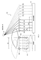
- FIG. 3 in the MIMO mode, a transmission wave having a wider directivity than that in the phased array mode is transmitted from each transmission antenna element.
- the number of receiving antenna elements virtually increases, and the estimation accuracy of the arrival direction of the reflected wave is improved.
- a virtual array antenna starting from a position 5Dr away from the receiving antenna element 60a can be configured.
- the virtual array antenna includes five virtual antenna elements 65a to 65e, like the receiving array antenna.
- the transmitting array antenna 50 and the receiving array antenna 60 are configured so that the positions of the plurality of receiving antenna elements do not match the virtual positions of the plurality of virtual antenna elements.
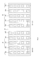
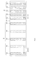
- FIG. 4 shows an example of the configuration of the transmitting array antenna 50 and the receiving array antenna 60.
- the transmitting array antenna 50 and the receiving array antenna 60 are formed on the surface of an antenna substrate 55 that is a dielectric substrate.
- a ground plate which is a copper pattern covering the entire surface is formed.
- the transmitting antenna elements 50a to 50e and the receiving antenna elements 60a to 60e are arranged on a straight line on the antenna substrate 55.
- the arrangement direction of the transmission antenna elements 50a to 50e and the reception antenna elements 60a to 60e is referred to as an antenna arrangement direction.
- the transmitting array antenna 50 side is referred to as the left side
- the receiving array antenna 60 side is referred to as the right side. That is, the left-right direction of the antenna substrate 55 is the antenna arrangement direction.
- Each of the transmitting antenna elements 50a to 50e and the receiving antenna elements 60a to 60e includes a plurality of conductor patches.
- the plurality of conductor patches are rectangular copper patterns, and are arranged in a line at equal intervals along a direction orthogonal to the antenna arrangement direction.
- the receiving antenna elements 60a to 60e are arranged in the antenna arrangement direction at equal intervals of the interval Dr.
- the transmitting antenna elements 50a to 50e are arranged in the antenna arrangement direction at equal intervals of the interval Dt.
- Dr ⁇ / 2 is set.
- the distance between the leftmost receiving antenna element 60a and the rightmost receiving antenna element is 4Dr. Therefore, if the virtual array antenna is configured starting from a position 5 Dr away from the receiving antenna element 60a, the positions of the receiving antenna elements 60a to 60e and the virtual positions of the virtual antenna elements 65a to 65e do not overlap.
- At least one of the intervals between two different transmission antenna elements may be set to N ⁇ Dr or more.
- N is the number of receiving antenna elements.
- Dr is an interval between adjacent receiving antenna elements.
- the transmission control unit 32 selects the transmission antenna elements 50a and 50e in the MIMO mode, the virtual antenna elements 65a to 65e can be configured at positions that do not overlap with the reception antenna elements 60a to 60e.
- the interval Dt between adjacent transmitting antenna elements is set to be equal to or larger than Dr ⁇ N / (M ⁇ 1), the distance between the leftmost transmitting antenna element and the rightmost transmitting antenna element is always equal to or larger than N ⁇ Dr. M is the number of transmitting antenna elements. Therefore, in this case, in the MIMO mode, if the transmission control unit 32 selects the leftmost transmission antenna element and the rightmost transmission antenna element, the virtual antenna element can be configured at a position that does not overlap the reception antenna element.
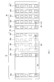
- FIG. 6 shows another configuration example of the transmission array antenna 50.
- Dt 5/2 ⁇ Dr is set. Therefore, the distance between the leftmost transmission antenna element 50a and the central transmission antenna element 50c and the distance between the central transmission antenna element 50c and the rightmost transmission antenna element 50e are 5 Dr. Therefore, in this example, in the MIMO mode, even if the transmission control unit 32 selects the transmission antenna element 50c in addition to the transmission antenna elements 50a and 50e, the virtual antenna element does not overlap the reception antenna elements 60a to 60e. Can be configured. In this case, although the antenna substrate 55 is larger than the example of FIG. 4, the number of receiving antenna elements is virtually tripled, and thus the accuracy of estimating the orientation of the target P is further improved.
- FIG. 7 shows another configuration example of the transmission array antenna 50.
- the transmission array antenna 50 includes six transmission antenna elements 50a to 50f.
- the transmitting antenna elements 50a to 50f are not installed at equal intervals.
- the transmitting antenna elements may not be arranged at equal intervals on the straight line.
- the relationship between the number of transmitting antenna elements and receiving antenna elements and the distance between two different transmitting antenna elements may satisfy the above-described relationship.
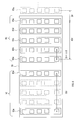
- the radar apparatus 100 is mounted at four locations on the left front side, right front side, left rear side, and right rear side of the host vehicle V1. Specifically, the transmitting array antenna 50 and the receiving array antenna 60 are installed at the four locations.
- the object to be noted differs depending on the traveling state of the host vehicle V1.
- the host vehicle V1 When the host vehicle V1 is traveling at a relatively low speed near an intersection or in a parking lot, the host vehicle V1 should be careful of a vehicle that crosses the front and rear of the host vehicle V1.
- the other vehicle when the host vehicle V1 is traveling on the roadway at a relatively high speed, the other vehicle usually does not cross the front and rear of the host vehicle V1, so that the host vehicle V1 approaches from the front and rear of the host vehicle V1.
- the radar apparatus 100 selects and executes an application for a different detection operation according to the traveling state of the host vehicle V1.
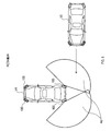
- Fig. 8 shows the state of the RCAT operation.
- RCAT stands for Rear ⁇ CrossRTraffic Alert.
- the RCAT operation is an operation for detecting another vehicle V2 crossing the rear of the host vehicle V1.
- the transmission control unit 32 operates the radar apparatus 100 mounted on the left rear and right rear of the host vehicle V1 in the MIMO mode.
- the detection area Ad extends in a wide range and ranges from a left rear and right rear radar device 100 to a relatively close distance.
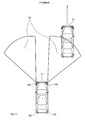
- FIG. 9 shows the state of the RCVW operation.
- RCVW is an abbreviation for Rear Closing Vehicle Warning.
- the RCVW operation is an operation for detecting another vehicle V2 approaching from behind the host vehicle V1.
- the transmission control unit 32 operates the radar device 100 mounted on the left rear and the right rear of the host vehicle V1 in the phased array mode.
- the detection area Ad has a narrow range of directions and a range from the left rear and right rear radar devices 100 to a relatively far distance.
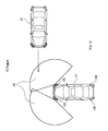
- FIG. 10 shows the FCTA operation.
- FCTA stands for Front Cross Traffic Alert.
- the FCTA operation is an operation for detecting another vehicle V2 crossing the front of the host vehicle V1.
- the transmission control unit 32 operates the radar apparatus 100 mounted on the left front and right front of the host vehicle V1 in the MIMO mode.
- the detection area Ad extends in a wide range and ranges from a left front and a right front radar device 100 to a relatively close distance.
- FIG. 11 shows the FCVW operation.
- FCVW stands for Front Closing Vehicle Warning.
- the FCVW operation is an operation for detecting another vehicle V2 approaching from the front of the host vehicle V1.
- the transmission control unit 32 causes the radar apparatus 100 mounted on the left front and right front of the host vehicle V1 to operate in the phased array mode.
- the detection area Ad similarly to the RCVW operation, the detection area Ad has a narrow range of directions and a range from the front and rear and the front and rear radar devices 100 to a relatively far distance.
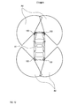
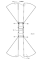
- FIG. 12 shows the CTA operation.
- movement is operation
- the transmission control unit 32 operates the four radar devices 100 of the host vehicle V1 in the MIMO mode.
- the detection area Ad is a range in which the detection area during the RCTA operation and the detection area during the FCTA operation are combined.
- FIG. 13 shows the CVW operation.
- the CVW operation is an operation for detecting another vehicle V2 approaching from the front and rear of the host vehicle V1.
- the transmission control unit 32 operates the four radar devices 100 of the host vehicle V1 in the phased array mode.
- the detection area Ad is a range in which the detection area during the RCVW operation and the detection area during the FCVW operation are combined.
- the RCTA operation, the FCTA operation, and the CTA operation correspond to a crossing vehicle detection operation
- the RCVW operation, the FCVW operation, and the CVW operation correspond to an approaching vehicle detection operation
- the radar apparatus 100 performs a CTA operation as a crossing vehicle detection operation and performs a CVW operation as an approaching vehicle detection operation.
- the installation location and the number of the radar devices 100 are not limited to the above example.
- the radar devices 100 may be mounted at the front center and the rear center of the host vehicle V1, or only two may be mounted at the front center and the rear center. .
- one radar apparatus 100 may be mounted at the front center, or two radar apparatuses 100 may be mounted at the left front and right front. Three may be mounted in the front center, left front, and right front.
- one radar apparatus 100 may be mounted in the rear center, or two may be mounted on the left rear and the right rear. The rear center, the rear left and the rear right may be mounted three.
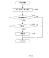
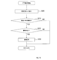
- Target detection processing Next, the processing procedure of the target detection process for detecting the target P around the host vehicle will be described with reference to the flowcharts of FIGS. This processing procedure is repeatedly executed for each radar apparatus 100 by the transmission unit 30 and the signal processing unit 70 at a predetermined cycle.
- the signal processing unit 70 takes over data such as the relative speed, distance, and direction of the target P detected in the previous processing cycle. That is, the signal processing unit 70 reads out data acquired in the previous processing cycle and stored in the memory.
- the transmission unit 30 determines whether or not the vehicle speed of the host vehicle V1 received from the vehicle speed sensor 11 is equal to or higher than a preset vehicle speed threshold value Vth.
- Vth is, for example, 30 km / h.
- the process proceeds to S30, and the CVW operation is selected and executed.
- the process proceeds to S40 to select and execute the CTA operation.
- the vehicle speed threshold value Vth may be set in two stages of Vth1, Vth2, and Vth1> Vth2.
- the values of Vth1 and Vth2 are, for example, 40 km / h and 20 km / h.
- the process proceeds to S30 when the vehicle speed is equal to or higher than the vehicle speed threshold Vth2, and proceeds to step S40 when the vehicle speed is less than the vehicle speed threshold Vth2.
- the CAT operation is selected in the preprocessing cycle
- the process proceeds to S30 when the vehicle speed is equal to or higher than the vehicle speed threshold Vth1, and to S40 when the vehicle speed is less than the vehicle speed threshold Vth1.
- frequent switching of the detection operation is suppressed by setting the vehicle speed threshold value in two stages.
- the transmission unit 30 and the signal processing unit 70 execute the CVW operation and output an alarm when there is a possibility of a collision with another vehicle V2.
- the transmission unit 30 and the signal processing unit 70 execute a CTA operation and output an alarm when there is a possibility of a collision with another vehicle V2.
- the signal processing unit 70 takes over data such as the relative speed, distance, and direction of the target P detected in the current processing cycle in the next processing cycle. That is, the signal processing unit 70 stores the data acquired in the current processing cycle in the memory. This process is complete
- the transmission unit 30 operates the radar apparatus 100 in the phased array mode and transmits a transmission wave.
- the signal processing unit 70 determines whether or not the other vehicle V2 approaching the host vehicle V1 from the front-rear direction is detected. Specifically, the signal processing unit 70 generates a beat signal from the transmission signal and the reception signal, detects the moving target P from the generated beat signal, and detects the relative speed, distance, Estimate the direction.
- the signal processing unit 70 calculates the movement vector of the target P from the data in the previous processing cycle taken over in S10 and the data acquired in the current processing cycle.
- the signal processing unit 70 calculates a movement vector for each target P.
- the signal processing unit 70 determines that the approaching other vehicle V2 is detected when the calculated movement vector is directed from the front and back of the host vehicle V1 toward the host vehicle V1.
- the signal processing unit 70 determines that the approaching other vehicle V2 is not detected when the target P is not detected and when the movement vector is not directed toward the host vehicle V1.
- the signal processing unit 70 determines whether or not to output an alarm. That is, the signal processing unit 70 determines whether or not the approaching other vehicle V2 and the host vehicle V1 may collide. Specifically, the signal processing unit 70 determines that there is a possibility of collision when one or more of the following conditions (i) to (iv) are satisfied, and determines to output an alarm.
- the other vehicle V2 exists within the distance threshold Rth from the host vehicle V1.
- the relative speed of the other vehicle V2 is equal to or higher than the speed threshold Vrth.
- the other vehicle V2 has been detected more than the number of times threshold value Xth so far.
- the lateral distance between the host vehicle V1 and the other vehicle V2 is within the distance threshold Wth, and the host vehicle V1 operates the direction indicator in the direction of the other vehicle V2.
- the transmission unit 30 operates the radar apparatus 100 in the MIMO mode to transmit a transmission wave.
- the signal processing unit 70 calculates a movement vector of the target P, as in the processing of S110. When the calculated movement vector is directed from the lateral direction of the host vehicle V1 toward the host vehicle V1, the signal processing unit 70 determines that the other vehicle V2 being crossed is detected. The signal processing unit 70 determines that the other vehicle V2 being crossed is not detected when the target P is not detected and when the movement vector is not directed toward the host vehicle V1.
- the signal processing unit 70 determines whether or not to output an alarm. That is, the signal processing unit 70 determines whether or not there is a possibility that the other vehicle V2 that is crossing and the host vehicle V1 collide. Specifically, the signal processing unit 70 determines to output an alarm when the following condition (v) is satisfied. (V) The moving direction of the host vehicle V1 and the moving direction of the other vehicle V2 intersect, and the intersection is reached within the time threshold Tth.
- the radar apparatus 100 can be operated in one of the phased array mode and the MIMO mode.
- the phased array mode is selected, so that the target existing in the specific direction can be detected with high accuracy.
- the MIMO mode is selected, so that a virtual array antenna can be configured to accurately estimate the direction of the target detected in a wide range of directions. . Therefore, it is possible to realize excellent performance by effectively using the hardware configuration of the radar apparatus 100 including a plurality of transmission radar elements.
- the distance Dt between adjacent transmitting antennas is set to be not less than Dr ⁇ N / (M ⁇ 1). As a result, if the outermost two transmitting antenna elements are selected when the MIMO mode is selected, the virtual array antenna can be configured at a position that does not overlap the position of the receiving array antenna 60.
- the target P to be detected is detected from the appropriate detection area Ad corresponding to the traveling state of the host vehicle V1.
- highly accurate information on the target P can be obtained.
- Either one of the CVW operation and the CTA operation is selected according to the vehicle speed of the host vehicle V1.
- the radar apparatus 100 operates in the phased array mode, and can accurately detect the other vehicle V2 approaching the host vehicle V1 from the front-rear direction.
- the radar apparatus 100 operates in the MIMO mode, detects the other vehicle V2 crossing the front and rear of the host vehicle V1, and can accurately estimate the direction of the other vehicle V2. .
- the radar apparatus 100 When the host vehicle V1 is traveling at a high speed equal to or higher than the speed threshold Vth, the radar apparatus 100 is in the phased array mode because attention should be paid to the other vehicle V2 approaching from the front-rear direction of the host vehicle V1. Operate. On the other hand, when the host vehicle V1 is traveling at a low speed less than the speed threshold Vth, the radar apparatus 100 operates in the MIMO mode because attention should be paid to other vehicles that cross the front and rear of the host vehicle V1. By doing in this way, according to the speed of the own vehicle V1, the highly accurate information of the other vehicle V2 which should be careful can be obtained.
- the front radar device 100 and the rear radar device 100 of the host vehicle V1 perform the same detection operation, but the front radar device 100 and the rear radar device 100 are: Different detection operations may be performed. Specifically, as shown by a broken line in FIG. 1, the detection operation selection unit 31 receives not only the vehicle speed information but also the shift position from the shift device 12, and based on the vehicle speed information and the shift position, the detection operation selection unit 31 Each detection operation may be selected.
- the rear radar apparatus 100 executes the RCVW operation regardless of the vehicle speed, and the front radar apparatus 100 executes the FCVW operation at high speed and the FCTA operation at low speed. May be.
- the rear radar apparatus 100 executes the RCTA operation regardless of the vehicle speed, and the front radar apparatus 100 executes the FCVW operation at high speed and the FCTA operation at low speed. May be.
- the front radar apparatus 100 and the rear radar apparatus 100 select the detection operation, the other vehicle to be noted can be detected more appropriately.
- the transmission frequency is changed by controlling the phase shifter, and transmission waves having different transmission frequencies are transmitted simultaneously.
- the present disclosure is limited to this. It is not a thing. As long as transmission waves that do not interfere with each other can be transmitted simultaneously from a plurality of transmission antenna elements by controlling the phase shifter, control other than the transmission frequency may be controlled.
- the phase shifter is not necessarily provided for each of the transmission antenna elements 50a to 50e. The phase shifter may be provided in each of at least two transmission antenna elements among the transmission antenna elements 50a to 50e.
- the radar apparatus 100 is mounted on a vehicle and used, but the present disclosure is not limited to this.
- the radar apparatus 100 may be installed at a predetermined measurement point to perform fixed point measurement.
- the radar apparatus 100 may be operated by switching between the phased array mode and the MIMO mode according to the measurement situation such as the weather.
- a plurality of functions of one constituent element in the above embodiment may be realized by a plurality of constituent elements, or a single function of one constituent element may be realized by a plurality of constituent elements. . Further, a plurality of functions possessed by a plurality of constituent elements may be realized by one constituent element, or one function realized by a plurality of constituent elements may be realized by one constituent element. Moreover, you may abbreviate
- at least a part of the configuration of the above embodiment may be added to or replaced with the configuration of the other embodiment.
- all the aspects included in the technical idea specified only by the wording described in the claim are embodiment of this indication.
- the present disclosure can be realized in various forms such as a system including the radar apparatus as a constituent element and an object detection method.
Abstract
送信アレーアンテナ(50)と、移相器(41a~41e)と、受信アレーアンテナ(60)と、送信制御部(32)と、信号処理部(70)と、を備える。前記送信制御部は、指向性制御モード及びMIMOモードのうちのいずれか一方の動作モードにより、送信波を送信する。前記指向性制御モードは、前記移相器を制御することにより前記送信アレーアンテナの指向性を制御する。前記MIMOモードは、選択した少なくとも2つの送信アンテナ素子から互いに干渉しないように送信波を送信する。
Description
本国際出願は、2017年2月22日に日本国特許庁に出願された日本国特許出願第2017-031309号に基づく優先権を主張するものであり、日本国特許出願第2017-031309号の全内容を参照により本国際出願に援用する。
本開示は、レーダ装置に関する。
特許文献1には、送信アレーアンテナと、送信アレーアンテナに含まれる単位アンテナごとに設けられた移相器と、受信アレーアンテナと、を備え、車両に搭載されたレーダ装置が記載されている。上記レーダ装置は、車両の前進時には、自車両に後方から接近する車両を検知する後方接近車両検知モードで動作し、車両の後退時には、自車両の後方を横切る車両を検知する後退時横切り車両検知モードで動作する。そして、上記レーダ装置は、各モードで動作する際に、検知エリアを各モードに適した範囲に設定している。
後方接近車両検知モードでは、検知エリアを後方向に制限した範囲に設定することが望ましく、移相器を制御して、指向性を制御することが有効である。一方、後退時横切り車両検知モードでは、検知エリアを幅広い方向の範囲に設定することが望ましく、指向性を制御する必要がない。後退時横切り車両検知モードでレーダ装置を動作させる場合、単位アンテナは一つでよい。発明者の詳細な検討の結果、上記レーダ装置は、指向性を制御する必要がない場合に単位アンテナが過剰となるため、上記レーダ装置にはハードウェア構成をより有効に利用できる余地があるという課題が見出された。
本開示の1つの局面は、ハードウェア構成を有効に利用して、優れた性能を実現したレーダ装置を提供できることが望ましい。
本開示の1つの局面は、レーダ装置であって、送信アレーアンテナと、移相器と、受信アレーアンテナと、送信制御部と、信号処理部と、を備える。前記送信アレーアンテナは、複数の送信アンテナ素子を備え、送信波を送信するように構成されている。前記移相器は、少なくとも2つの前記送信アンテナ素子のそれぞれに設けられ、前記移相器が設けられた送信アンテナ素子から送信される送信波の位相を変化させるように構成されている。前記受信アレーアンテナは、複数の受信アンテナ素子を備え、送信された送信波が物標で反射されて生じた反射波を受信するように構成されている。前記送信制御部は、指向性制御モード及びMIMOモードのうちのいずれか一方の動作モードにより、前記送信波を前記送信アレーアンテナを介して送信するように構成されている。前記指向性制御モードは、前記移相器を制御することにより前記送信アレーアンテナの指向性を制御する前記レーダ装置の動作モードである。前記MIMOモードは、前記複数の送信アンテナ素子の中から少なくとも2つの送信アンテナ素子を選択し、選択した送信アンテナ素子から互いに干渉しないように前記送信波を送信する前記レーダ装置の動作モードである。前記信号処理部は、前記受信アレーアンテナにより受信された前記反射波から、前記物標の方位を推定するように構成されている。
本開示の1つの局面は、レーダ装置であって、送信アレーアンテナと、移相器と、受信アレーアンテナと、送信制御部と、信号処理部と、を備える。前記送信アレーアンテナは、複数の送信アンテナ素子を備え、送信波を送信するように構成されている。前記移相器は、少なくとも2つの前記送信アンテナ素子のそれぞれに設けられ、前記移相器が設けられた送信アンテナ素子から送信される送信波の位相を変化させるように構成されている。前記受信アレーアンテナは、複数の受信アンテナ素子を備え、送信された送信波が物標で反射されて生じた反射波を受信するように構成されている。前記送信制御部は、指向性制御モード及びMIMOモードのうちのいずれか一方の動作モードにより、前記送信波を前記送信アレーアンテナを介して送信するように構成されている。前記指向性制御モードは、前記移相器を制御することにより前記送信アレーアンテナの指向性を制御する前記レーダ装置の動作モードである。前記MIMOモードは、前記複数の送信アンテナ素子の中から少なくとも2つの送信アンテナ素子を選択し、選択した送信アンテナ素子から互いに干渉しないように前記送信波を送信する前記レーダ装置の動作モードである。前記信号処理部は、前記受信アレーアンテナにより受信された前記反射波から、前記物標の方位を推定するように構成されている。
本開示の1つの局面によれば、指向性制御モード及びMIMOモードのうちのいずれか一方の動作モードにより、送信波が送信される。そして、送信された送信波が物標で反射して生じた反射波が、受信アレーアンテナにより受信され、受信された反射波から物標の方位が推定される。
よって、特定方向に存在する物標を検知したい場合には、指向性制御モードでレーダ装置を動作させることにより、特定方向に存在する物標を精度良く検知することができる。一方、幅広い方向の範囲に存在する物標を検知したい場合には、MIMOモードでレーダ装置を動作させることにより、仮想的に受信アンテナ素子数を増加させて、レーダ装置の方位分解能を向上させることができる。ひいては、幅広い方向の範囲で検知された物標の方位を精度良く推定することができる。すなわち、複数の送信アンテナ素子を備えるレーダ装置のハードウェア構成を有効に利用して、優れた性能を実現することができる。
なお、請求の範囲に記載した括弧内の符号は、一つの態様として後述する実施形態に記載の具体的手段との対応関係を示すものであって、本開示の技術的範囲を限定するものではない。
以下、図面を参照しながら、本開示を実施するための形態を説明する。
<1.全体構成>
まず、本実施形態に係るレーダ装置100の構成について、図1を参照して説明する。本実施形態では、レーダ装置100は車両に搭載されることを想定している。レーダ装置100は、送信部30、信号制御部40、送信アレーアンテナ50、受信アレーアンテナ60、及び信号処理部70を備えるミリ波レーダである。
<1.全体構成>
まず、本実施形態に係るレーダ装置100の構成について、図1を参照して説明する。本実施形態では、レーダ装置100は車両に搭載されることを想定している。レーダ装置100は、送信部30、信号制御部40、送信アレーアンテナ50、受信アレーアンテナ60、及び信号処理部70を備えるミリ波レーダである。
送信部30は、検知動作選択部31及び送信制御部32を備える。検知動作選択部31は、計測状況に基づいて、複数の検知動作の中から適した検知動作を選択する。複数の検知動作は、互いに検知エリアAdが異なる動作であり、詳細については後述する。本実施形態では、車速センサ11から受信した自車両の車速情報に基づいて、複数の検知動作の中から適した検知動作を選択する。
送信制御部32は、検知動作選択部31により選択された検知動作に応じた動作モードで、レーダ装置100を動作させる。つまり、送信制御部32は、選択された検知動作に応じた動作モードで、送信アレーアンテナ50から送信波を送信する。具体的には、送信制御部32は、変調信号、変調信号に従って変調された送信信号、及び送信制御信号を生成し、生成した送信信号及び送信制御信号を信号制御部40へ供給する。なお、変調方式は、2周波CW方式や、多周波CW方式、FMCW方式など何でもよく、特に限定されるものではない。
信号制御部40は、移相器41a~41eと、移相器41a~41eに対応した増幅器42a~42eを備える。移相器41a~41eのそれぞれと、増幅器42a~42eのそれぞれとのセットは、それぞれ、送信部30と、送信アレーアンテナ50に含まれる送信アンテナ素子50a~50eのそれぞれとの間の伝送路に接続されている。移相器41a~41eは、送信制御信号に従って、送信信号の位相を制御する。また、増幅器42a~42eは、送信制御信号に従って、送信信号の振幅を制御する。増幅器42a~42eは、増幅率をゼロに設定することで、伝送路を遮断するスイッチとしても機能する。
送信アレーアンテナ50は、M(Mは2以上の整数)個の送信アンテナ素子を含むアレーアンテナである。図1に示す例では、M=5であり、送信アレーアンテナ50は、5個の送信アンテナ素子50a~50eを備える。送信アンテナ素子50a~50eは、それぞれ、増幅器42a~42eから出力された送信信号に基づいて、電磁波である送信波を送信する。このとき、増幅器42a~42eの中に、増幅率がゼロに設定されている増幅器がある場合、増幅率がゼロに設定された増幅器からは送信信号が出力されず、対応する送信アンテナ素子から送信波が出力されない。
受信アレーアンテナ60は、N(Nは2以上の整数)個の受信アンテナ素子を含むアレーアンテナである。図1に示す例では、N=5であり、受信アレーアンテナ60は、5個の受信アンテナ素子60a~60eを備える。受信アンテナ素子60a~60eは、それぞれ、送信波が物標Pで反射されて生じた反射波を受信信号として受信する。そして、受信アンテナ素子60a~60eは、それぞれ、受信した受信信号を信号処理部70へ出力する。
信号処理部70は、送信部30から供給された送信信号と、受信アレーアンテナ60から出力された受信信号とを混合して、ビート信号を生成する。そして、信号処理部70は、ビート信号から、レーダ装置100に対する物標Pの相対速度及び位置を推定する。詳しくは、信号処理部70は、ビート信号を周波数解析して、移動している物標Pを検出するとともにレーダ装置100に対する検出した物標Pの相対速度及び距離を推定する。さらに、信号処理部70は、ビート信号に、DBF、Capon、MUSIC等の方位展開アルゴリズムを適用して、反射波の到来方向、すなわち、レーダ装置100に対する物標Pの方位を推定する。なお、DBFは、Digital Beam Formingの略であり、MUSICは、Multiple Signal Classificationの略である。
さらに、信号処理部70は、推定した物標Pの相対速度、距離、及び方位に基づいて、物標Pが自車両と衝突する可能性を判定し、衝突する可能性がある場合には、ドライバに注意を促すために、警報装置200から警報を出力させる。なお、送信部30及び信号処理部70の機能は、CPUがメモリに記憶されているプログラムを実行することにより実現してもよいし、論理回路やアナログ回路等を組み合わせたハードウェアを用いて実現してもよい。また、送信部30及び信号処理部70の機能は、ソフトウェアとハードウェアの両方を用いて実現してもよい。
警報装置200は、ドアミラーや車室内に設けられたインジケータや、車室内のスピーカ、車室内のディスプレイなどである。警報装置200は、信号処理部70からの警報出力の指示に応じて、点滅したり、警告音や音声を出力したり、警告を表示したりする。
<2.動作モード>
次に、レーダ装置100の動作モードについて、図2及び図3を参照して説明する。レーダ装置100の動作モードには、フェーズドアレーモードとMIMOモードの2つのモードが存在する。MIMOは、Multi Input Multi Outputの略である。
次に、レーダ装置100の動作モードについて、図2及び図3を参照して説明する。レーダ装置100の動作モードには、フェーズドアレーモードとMIMOモードの2つのモードが存在する。MIMOは、Multi Input Multi Outputの略である。
フェーズドアレーモードは、移相器41a~41eを用いて、送信アンテナ素子50a~50eのそれぞれから送信される送信波の位相を個別に制御することで、送信アレーアンテナ50から送信される送信波の指向性を制御する動作モードである。図2に示すように、レーダ装置100をフェーズドアレーモードで動作させると、特定方向にMIMOモードよりも狭い指向性を持った送信波が送信される。本実施形態では、フェーズドアレーモードが指向性制御モードに相当する。
MIMOモードは、図3に示すように、送信アンテナ素子50a~50eの中から、少なくとも2つの送信アンテナ素子を選択し、選択した送信アンテナ素子から送信波を送信する動作モードである。送信制御部32は、MIMOモードにおいて、選択した複数の送信アンテナ素子から送信された送信波が互いに干渉しないように、異なる送信アンテナ素子からは、互いに異なる周波数の送信波を同時に送信する。または、送信制御部32は、MIMOモードにおいて、選択した複数の送信アンテナから送信された送信波が互いに干渉しないように、異なる送信アンテナ素子からは、互いに異なるタイミングで送信波を送信する。つまり、送信制御部32は、MIMOモードにおいて、周波数多重または時間多重で、複数の送信アンテナ素子から送信波を送信する。本実施形態では、送信制御部32は、MIMOモードにおいて、周波数多重で複数の送信アンテナ素子から送信波を送信する。また、送信制御部32は、MIMOモードにおいて、選択していない送信アンテナ素子からは送信波を送信しないように、選択していない送信アンテナ素子に対応する増幅器の増幅率をゼロに設定する。
送信制御部32は、周波数多重で複数の送信アンテナ素子から送信波を送信する場合には、選択した複数の送信アンテナ素子に設けられた移相器のうちの少なくとも1つの移相器を制御して、送信波の周波数をフェーズドアレーモード時の周波数からずらす。例えば、送信制御部32は、MIMOモードにおいて2つの送信アンテナ素子を選択した場合には、どちらか一方の送信アンテナ素子に設けられた1つの移相器を制御すればよい。そして、送信制御部32は、一方の送信アンテナ素子から送信される送信波の周波数をずらし、他方の送信アンテナ素子から送信される送信波の周波数はフェーズドアレーモードの時と同じ周波数とすればよい。また、送信制御部32は、MIMOモードにおいて3つの送信アンテナ素子を選択した場合には、3つの送信アンテナ素子のうちの2つに設けられた移相器をそれぞれ制御して、3つの送信アンテナ素子から送信される周波数が互に異なるようにすればよい。送信制御部32により移相器を制御して、送信波の位相を連続的に変化させることで、送信波の周波数を変化させることができる。図3に示すように、MIMOモードでは、各送信アンテナ素子から、フェーズドアレーモードよりも広い指向性を持った送信波が送信される。
レーダ装置100をMIMOモードで動作させると、仮想的に受信アンテナ素子が増加して、反射波の到来方向の推定精度が向上する。図3に示すように、5Drの距離離れて設けられた送信アンテナ素子50a,50eを選択すると、受信アンテナ素子60aから5Drの距離離れた位置を起点とする仮想アレーアンテナを構成できる。仮想アレーアンテナは、受信アレーアンテナと同じように、5つの仮想アンテナ素子65a~65eを含む。2つの送信アンテナ素子50a,50eを選択したことにより、仮想的に受信アンテナ素子の数が2倍になるため、物標Pの方位の推定精度が向上する。
<3.アレーアンテナの構成>
次に、レーダ装置100の送信アレーアンテナ50及び受信アレーアンテナ60の構成について、図4~図7を参照して説明する。
次に、レーダ装置100の送信アレーアンテナ50及び受信アレーアンテナ60の構成について、図4~図7を参照して説明する。
レーダ装置100をMIMOモードで動作させる場合に、受信アンテナ素子の位置と仮想アンテナ素子の仮想的な位置とが重なると、受信アンテナ素子で受信された受信信号と、仮想アンテナ素子で受信された受信信号とを分離することができなくなる。その結果、物標Pの方位の推定精度の向上効果が低減する。よって、本実施形態では、複数の受信アンテナ素子の位置と、複数の仮想アンテナ素子の仮想的な位置とが一致しないように、送信アレーアンテナ50及び受信アレーアンテナ60を構成する。
図4に、送信アレーアンテナ50及び受信アレーアンテナ60の構成の一例を示す。図4に示すように、送信アレーアンテナ50及び受信アレーアンテナ60は、誘電体の基板であるアンテナ基板55の表面に形成されている。アンテナ基板55の裏面には、その全面を覆う銅パターンである地板が形成されている。送信アンテナ素子50a~50e及び受信アンテナ素子60a~60eは、アンテナ基板55上に、直線上に並べて配置されている。以下では、送信アンテナ素子50a~50e及び受信アンテナ素子60a~60eの配列方向をアンテナ配列方向と称する。また、送信アレーアンテナ50側を左側、受信アレーアンテナ60側を右側と称する。すなわち、アンテナ基板55の左右方向がアンテナ配列方向である。
送信アンテナ素子50a~50e及び受信アンテナ素子60a~60eのそれぞれは、複数の導体パッチを含んでいる。複数の導体パッチは、矩形状の銅パターンであり、アンテナ配列方向と直交する方向に沿って等間隔で一列に配置されている。
受信アンテナ素子60a~60eは、間隔Drの等間隔でアンテナ配列方向に並べられている。一方、送信アンテナ素子50a~50eは、間隔Dtの等間隔でアンテナ配列方向に並べられている。フェーズドアレーモード時の送信周波数における波長をλとした場合、Dr=λ/2に設定されている。ここで、図5に示すように、最も左側の受信アンテナ素子60aと最も右側の受信アンテナ素子との間隔は4Drとなっている。よって、受信アンテナ素子60aから5Dr離れた位置を起点として仮想アレーアンテナが構成されれば、受信アンテナ素子60a~60eの位置と仮想アンテナ素子65a~65eの仮想的な位置とが重なることがない。
つまり、互いに異なる2つの送信アンテナ素子の間隔のうち少なくとも1つは、N×Dr以上と設定すればよい。Nは受信アンテナ素子の数である。Drは隣り合う受信アンテナ素子の間隔である。このようにすると、MIMOモードにおいて、送信制御部32がN×Dr以上離れた2つ以上の送信アンテナ素子を選択すれば、最も右側の受信アンテナ素子60eよりも右側に、仮想アンテナ素子を構成することができる。
さらに、Dt=5/4×Drと設定すれば、図5に示すように、最も左側の送信アンテナ素子50aと最も右側の送信アンテナ素子50eとの間隔は5Drとなる。よって、この場合、MIMOモードにおいて、送信制御部32が送信アンテナ素子50a,50eを選択すれば、受信アンテナ素子60a~60eと重ならない位置に仮想アンテナ素子65a~65eを構成することができる。
隣り合う送信アンテナ素子の間隔DtをDr×N/(M-1)以上に設定すれば、最も左側の送信アンテナ素子と最も右側の送信アンテナ素子との間隔は必ずN×Dr以上となる。Mは送信アンテナ素子の数である。よって、この場合、MIMOモードにおいて、送信制御部32が最も左側の送信アンテナ素子と最も右側の送信アンテナ素子を選択すれば、受信アンテナ素子と重ならない位置に仮想アンテナ素子を構成することができる。
また、図6に、送信アレーアンテナ50の他の構成例を示す。この例では、Dt=5/2×Drに設定されている。そのため、最も左側の送信アンテナ素子50aと中央の送信アンテナ素子50cとの間隔、及び中央の送信アンテナ素子50cと最も右側の送信アンテナ素子50eとの間隔が、5Drとなっている。よって、この例では、MIMOモードにおいて、送信制御部32が、送信アンテナ素子50a,50eに加えて、送信アンテナ素子50cを選択しても、受信アンテナ素子60a~60eと重ならない位置に仮想アンテナ素子を構成することができる。この場合、図4の例と比べてアンテナ基板55は大型化するが、仮想的に受信アンテナ素子の数が3倍になるため、物標Pの方位の推定精度がより向上する。
また、図7に、送信アレーアンテナ50の他の構成例を示す。この例では、送信アレーアンテナ50は、6個の送信アンテナ素子50a~50fを含む。そして、送信アンテナ素子50a~50fは等間隔に設置されていない。送信アンテナ素子50aと送信アンテナ素子50bはDt=5Drの間隔で設置されており、送信アンテナ素子50b~50fは、Dt=5/4×Drの間隔で等間隔に設置されている。よって、この例では、MIMOモードにおいて、送信制御部32は、送信アンテナ素子50a,50b,50fを選択してもよい。このように、受信アンテナ素子が直線上に等間隔に並べられていれば、送信アンテナ素子は直線上に等間隔に並べられていなくてもよい。
なお、上記例では、送信アンテナ素子数と受信アンテナ素子数が同じ例と、送信アンテナ素子数が受信アンテナ素子数よりも多い例を示したが、受信アンテナ素子数が送信アンテナ素子数よりも多くてもよい。送信アンテナ素子及び受信アンテナ素子の素子数と異なる2つの送信アンテナ素子の間隔との関係が上述した関係を満たせばよい。
<4.検知動作>
次に、車両に搭載されたレーダ装置100が実行可能な検知動作について、図8~図13を参照して説明する。本実施形態では、レーダ装置100は、自車両V1の左前の側方、右前の側方、左後の側方、及び右後の側方の4箇所に搭載されている。詳しくは、送信アレーアンテナ50及び受信アレーアンテナ60が、上記4箇所にそれぞれ設置されている。
次に、車両に搭載されたレーダ装置100が実行可能な検知動作について、図8~図13を参照して説明する。本実施形態では、レーダ装置100は、自車両V1の左前の側方、右前の側方、左後の側方、及び右後の側方の4箇所に搭載されている。詳しくは、送信アレーアンテナ50及び受信アレーアンテナ60が、上記4箇所にそれぞれ設置されている。
ところで、自車両V1の走行状態に応じて、注意すべき対象が異なる。自車両V1が、交差点付近や駐車場などで比較的低速で走行している場合は、自車両V1は自車両V1の前後を横切る車両を注意すべきである。一方、自車両V1が車道を比較的高速で走行している場合は、通常、自車両V1の前後を他車両が横切ることはないので、自車両V1は自車両V1の前後から接近する他車両を注意すべきである。よって、レーダ装置100は、自車両V1の走行状態に応じて異なる検知動作のアプリケーションを選択して実行する。
図8に、RCAT動作の様子を示す。RCATは、Rear Cross Traffic Alertの略である。RCAT動作は、自車両V1の後方を横切る他車両V2を検知する動作である。RCAT動作の実行が選択されている場合は、送信制御部32は、自車両V1の左後及び右後に搭載されたレーダ装置100をMIMOモードで動作させる。この場合、検知エリアAdは、図8に示すように、幅広い方向に広がり、且つ、左後及び右後のレーダ装置100から比較的近い距離までの範囲となる。
次に、図9に、RCVW動作の様子を示す。RCVWは、Rear Closing Vehicle Warningの略である。RCVW動作は、自車両V1の後方から接近する他車両V2を検知する動作である。RCVW動作の実行が選択されている場合は、送信制御部32は、自車両V1の左後及び右後に搭載されたレーダ装置100をフェーズドアレーモードで動作させる。この場合、検知エリアAdは、図9に示すように、方向の広がりが狭く、且つ、左後及び右後のレーダ装置100から比較的遠い距離までの範囲となる。
次に、図10に、FCTA動作の様子を示す。FCTAは、Front Cross Traffic Alertの略である。FCTA動作は、自車両V1の前方を横切る他車両V2を検知する動作である。FCTA動作の実行が選択されている場合は、送信制御部32は、自車両V1の左前及び右前に搭載されたレーダ装置100をMIMOモードで動作させる。この場合、検知エリアAdは、RCTA動作と同様に、幅広い方向に広がり、且つ、左前及び右前のレーダ装置100から比較的近い距離までの範囲となる。
次に、図11に、FCVW動作の様子を示す。FCVWは、Front Closing Vehicle Warningの略である。FCVW動作は、自車両V1の前方から接近する他車両V2を検知する動作である。FCVW動作の実行が選択されている場合は、送信制御部32は、自車両V1の左前及び右前に搭載されたレーダ装置100をフェーズドアレーモードで動作させる。この場合、検知エリアAdは、RCVW動作と同様に、方向の広がりが狭く、且つ、前後及び前後のレーダ装置100から比較的遠い距離までの範囲となる。
次に、図12に、CTA動作の様子を示す。CTA動作は、自車両V1の前方及び後方を横切る他車両V2を検知する動作である。CTA動作の実行が選択されている場合は、送信制御部32は、自車両V1の4個のレーダ装置100をMIMOモードで動作させる。この場合、検知エリアAdは、RCTA動作時の検知エリアと、FCTA動作時の検知エリアとを合わせた範囲になる。
次に、図13に、CVW動作の様子を示す。CVW動作は、自車両V1の前方及び後方から接近する他車両V2を検知する動作である。CVW動作の実行が選択されている場合は、送信制御部32は、自車両V1の4個のレーダ装置100をフェーズドアレーモードで動作させる。この場合、検知エリアAdは、RCVW動作時の検知エリアと、FCVW動作時の検知エリアとを合わせた範囲になる。
なお、RCTA動作、FCTA動作、及びCTA動作が、横切り車両検知動作に相当し、RCVW動作、FCVW動作、及びCVW動作が、接近車両検知動作に相当する。本実施形態では、レーダ装置100は、横切り車両検知動作としてCTA動作を実行し、接近車両検知動作としてCVW動作を実行する。
また、レーダ装置100の設置場所及び個数は、上記例に限定されるものではない。例えば、4個のレーダ装置100に加えて、レーダ装置100は、自車両V1の前方中央及び後方中央に搭載されていてもよいし、前方中央及び後方中央に2個搭載されているだけでもよい。また、レーダ装置100にFCTA動作及びFCVW動作のみを実行させる場合は、レーダ装置100は、前方中央に1個搭載されていてもよいし、左前及び右前に2個搭載されていてもよいし、前方中央、左前及び右前に3個搭載されていてもよい。また、レーダ装置100にRCTA動作及びRCVW動作のみを実行させる場合は、レーダ装置100は、後方中央に1個搭載されていてもよいし、左後及び右後に2個搭載されていてもよいし、後方中央、左後及び右後に3個搭載されていてもよい。
<5.物標検知処理>
次に、自車両周辺の物標Pを検知する物標検知処理の処理手順について、図14~図16のフローチャートを参照して説明する。本処理手順は、レーダ装置100ごとに、送信部30及び信号処理部70が、所定周期で繰り返し実行する。
次に、自車両周辺の物標Pを検知する物標検知処理の処理手順について、図14~図16のフローチャートを参照して説明する。本処理手順は、レーダ装置100ごとに、送信部30及び信号処理部70が、所定周期で繰り返し実行する。
まず、S10では、信号処理部70が、前回の処理周期に検知した物標Pの相対速度、距離、方位などのデータを引き継ぐ。すなわち、信号処理部70が、前回の処理周期にて取得されメモリに格納されていたデータを読み出す。
続いて、S20では、送信部30が、車速センサ11から受信した自車両V1の車速が、予め設定されている車速閾値Vth以上か否か判定する。Vthの値は、例えば、30km/hとする。そして、車速が車速閾値Vth以上の場合には、S30へ進み、CVW動作を選択して実行する。一方、車速が車速閾値Vth未満の場合には、S40へ進み、CTA動作を選択して実行する。
このとき、車速閾値VthをVth1,Vth2、Vth1>Vth2の2段階に設定してもよい。Vth1,Vth2の値は、例えば、40km/h,20km/hとする。詳しくは、前処理周期でCVW動作を選択している場合は、車速が車速閾値Vth2以上のときに、S30へ進み、車速が車速閾値Vth2未満のときに、ステップS40へ進む。一方、前処理周期でCAT動作を選択している場合は、車速が車速閾値Vth1以上のときに、S30へ進み、車速が車速閾値Vth1未満のときに、S40へ進む。このように、車速閾値を2段階に設定することにより、検知動作の頻繁な切り替えが抑制される。
S30では、送信部30及び信号処理部70がCVW動作を実行して、他車両V2と衝突の可能性がある場合に警報を出力する。一方、S40では、送信部30及び信号処理部70がCTA動作を実行して、他車両V2と衝突の可能性がある場合に警報を出力する。S30でCVW動作を実行した後、及びS40でCTA動作を実行した後、S50へ進む。CVW動作の実行及びCTA動作の処理の詳細については後述する。
S50では、信号処理部70が、今回の処理周期で検知した物標Pの相対速度、距離、方位などのデータを次回の処理周期に引き継ぐ。すなわち、信号処理部70が、今回の処理周期にて取得したデータをメモリに格納する。以上で本処理を終了する。
<5-1.CVW動作>
次に、CVW動作の処理手順について、図15のフローチャートを参照して説明する。本処理手順は、送信部30及び信号処理部70が実行する。
次に、CVW動作の処理手順について、図15のフローチャートを参照して説明する。本処理手順は、送信部30及び信号処理部70が実行する。
まず、S100では、送信部30が、レーダ装置100をフェーズドアレーモードで動作させて、送信波を送信する。
続いて、S110では、信号処理部70が、自車両V1に前後方向から接近する他車両V2を検知したか否か判定する。詳しくは、信号処理部70が、送信信号と受信信号からビート信号を生成し、生成したビート信号から、移動している物標Pを検出するとともに、検出した物標Pの相対速度、距離、方位を推定する。
続いて、S110では、信号処理部70が、自車両V1に前後方向から接近する他車両V2を検知したか否か判定する。詳しくは、信号処理部70が、送信信号と受信信号からビート信号を生成し、生成したビート信号から、移動している物標Pを検出するとともに、検出した物標Pの相対速度、距離、方位を推定する。
そして、信号処理部70は、S10で引き継いだ前回の処理周期のデータと、今回の処理周期で取得したデータとから、物標Pの移動ベクトルを算出する。信号処理部70は、複数の物標Pを検出した場合には、物標Pごとに、移動ベクトルを算出する。
さらに、信号処理部70は、算出した移動ベクトルが、自車両V1の前後から自車両V1に向かっている場合は、接近中の他車両V2を検知したと判定する。信号処理部70は、物標Pを検知していない場合、及び、移動ベクトルが自車両V1に向かっていない場合は、接近中の他車両V2を検知していないと判定する。
S110において、信号処理部70が接近中の他車両V2を検知したと判定した場合には、S120へ進む。一方、S110において、信号処理部70はが接近中の他車両V2を検知していないと判定した場合には、本処理を終了し、S50の処理へ進む。
S120では、信号処理部70が、警報を出力するか否か判定する。すなわち、信号処理部70は、接近中の他車両V2と自車両V1が衝突する可能性があるか否か判定する。詳しくは、信号処理部70は、以下の条件(i)~(iv)のうちの1つまたは複数の条件を満たす場合に、衝突する可能性があると判定し、警報を出力すると判定する。(i)自車両V1の走行方向において、他車両V2が自車両V1から距離閾値Rth以内に存在する。(ii)他車両V2の相対速度が速度閾値Vrth以上である。(iii)これまでに他車両V2を回数閾値Xth以上検知している。(iv)自車両V1と他車両V2の横方向の距離が距離閾値Wth以内で、且つ、自車両V1が他車両V2の方向に方向指示器を操作している。
S120において、信号処理部70が警報を出力すると判定した場合は、S130へ進み、警報装置200から警報を出力させる。そして、本処理を終了し、S50の処理へ進む。一方、S120において、信号処理部70が警報を出力しないと判定した場合は、本処理を終了し、S50の処理へ進む。
<5-2.CTA動作>
次に、CTAの処理手順について、図16のフローチャートを参照して説明する。本処理手順は、送信部30及び信号処理部70が実行する。
次に、CTAの処理手順について、図16のフローチャートを参照して説明する。本処理手順は、送信部30及び信号処理部70が実行する。
まず、S200では、送信部30が、レーダ装置100をMIMOモードで動作させて、送信波を送信する。
続いて、S210では、信号処理部70が、自車両V1の前後を横切る他車両V2を検知したか否か判定する。詳しくは、S110の処理と同様に、信号処理部70は物標Pの移動ベクトルを算出する。そして、信号処理部70は、算出した移動ベクトルが自車両V1の横方向から自車両V1に向かっている場合には、横切り中の他車両V2を検知したと判定する。信号処理部70は、物標Pを検知していない場合、及び、移動ベクトルが自車両V1に向かっていない場合は、横切り中の他車両V2を検知していないと判定する。
続いて、S210では、信号処理部70が、自車両V1の前後を横切る他車両V2を検知したか否か判定する。詳しくは、S110の処理と同様に、信号処理部70は物標Pの移動ベクトルを算出する。そして、信号処理部70は、算出した移動ベクトルが自車両V1の横方向から自車両V1に向かっている場合には、横切り中の他車両V2を検知したと判定する。信号処理部70は、物標Pを検知していない場合、及び、移動ベクトルが自車両V1に向かっていない場合は、横切り中の他車両V2を検知していないと判定する。
S210において、信号処理部70が横切り中の他車両V2を検知したと判定した場合は、S220へ進む。一方、S210において、信号処理部70が横切り中の他車両V2を検知していないと判定した場合は、本処理を終了し、S50の処理へ進む。
S220では、S120の処理と同様に、信号処理部70が、警報を出力するか否か判定する。すなわち、信号処理部70は、横切り中の他車両V2と自車両V1が衝突する可能性があるか否か判定する。詳しくは、信号処理部70は、以下の条件(v)を満たす場合に、警報を出力すると判定する。(v)自車両V1の移動方向と他車両V2の移動方向が交差し、且つ、その交差点に時間閾値Tth以内に到達する。
S220において、信号処理部70が警報を出力すると判定した場合は、S230へ進み、警報装置200から警報を出力させる。そして、本処理を終了し、50の処理へ進む。一方、S220において、信号処理部70が警報を出力しないと判定した場合は、本処理を終了し、S50の処理へ進む。
<5.効果>
以上説明した本実施形態によれば、以下の効果が得られる。
(1)フェーズドアレーモード及びMIMOモードのうちのいずれか一方により、レーダ装置100を動作させることができる。特定方向に存在する物標Pを検知すべき状況では、フェーズドアレーモードが選択されるため、特定方向に存在する物標を精度良く検知することができる。一方、幅広い方向に存在する物標を検知すべき状況では、MIMOモードが選択されるため、仮想アレーアンテナが構成されて、幅広い方向で検知された物標の方位を精度良く推定することができる。したがって、複数の送信レーダ素子を備えるレーダ装置100のハードウェア構成を有効に利用して、優れた性能を実現することができる。
(2)MIMOモードの選択時に、送信アレーアンテナ50の指向性を制御するために設けられている移相器41a~41eを用いることで、2つ以上の送信アンテナ素子から互いに異なる送信波を同時に送信することができる。つまり、フェーズドアレーモード用のハードウェアをより有効に利用して、MIMOモードでレーダ装置100を動作させることができる。
(3)MIMOモードの選択時に、移相器41a~41eを制御することにより、2つ以上の送信アンテナ素子から互いに異なる周波数の送信波を送信することができる。
(4)送信アンテナ素子の間隔のうち少なくとも1つは、N×Dr以上に設定される。これにより、MIMOモードの選択時に、互いの間隔がN×Dr以上となる2つ以上の送信アンテナ素子を選択すれば、受信アレーアンテナ60の位置と重ならない位置に仮想アレーアンテナを構成することができる。ひいては、受信アンテナ素子で受信した受信信号と、仮想アンテナ素子で受信した受信信号とを分離することができる。
(4)送信アンテナ素子の間隔のうち少なくとも1つは、N×Dr以上に設定される。これにより、MIMOモードの選択時に、互いの間隔がN×Dr以上となる2つ以上の送信アンテナ素子を選択すれば、受信アレーアンテナ60の位置と重ならない位置に仮想アレーアンテナを構成することができる。ひいては、受信アンテナ素子で受信した受信信号と、仮想アンテナ素子で受信した受信信号とを分離することができる。
(5)隣り合う送信アンテナの間隔Dtが、Dr×N/(M-1)以上に設定される。これにより、MIMOモードの選択時に、最も外側の2つの送信アンテナ素子を選択すれば、受信アレーアンテナ60の位置と重ならない位置に仮想アレーアンテナを構成することができる。
(6)自車両V1の走行状態に応じて、フェーズドアレーモードとMIMOモードとを切り替えることにより、自車両V1の走行状態に応じた適切な検知エリアAdから、検知するべき物標Pを検知して、物標Pの高精度な情報を得ることができる。
(7)自車両V1の車速に応じて、CVW動作及びCTA動作のうちのいずれか一方の検知動作が選択される。そして、CVW動作が選択された場合には、レーダ装置100はフェーズドアレーモードで動作し、自車両V1に前後方向から接近する他車両V2を精度良く検知することができる。一方、CTA動作が選択された場合には、レーダ装置100は、MIMOモードで動作し、自車両V1の前後を横切る他車両V2を検知し、他車両V2の方位を精度良く推定することができる。
(8)自車両V1が速度閾値Vth以上の高い速度で走行している場合は、自車両V1の前後方向から接近する他車両V2に注意すべきであるため、レーダ装置100はフェーズドアレーモードで動作する。一方、自車両V1が速度閾値Vth未満の低い速度で走行している場合は、自車両V1の前後を横切る他車両に注意すべきであるため、レーダ装置100はMIMOモードで動作する。このようにすることにより、自車両V1の速度に応じて、注意すべき他車両V2の高精度な情報を得ることができる。
(他の実施形態)
以上、本開示を実施するための形態について説明したが、本開示は上述の実施形態に限定されることなく、種々変形して実施することができる。
以上、本開示を実施するための形態について説明したが、本開示は上述の実施形態に限定されることなく、種々変形して実施することができる。
(a)上記実施形態では、自車両V1の前方のレーダ装置100と後方のレーダ装置100とは、同じ検知動作を実行しているが、前方のレーダ装置100と後方のレーダ装置100とは、異なる検知動作を実行してもよい。具体的には、図1に破線で示すように、検知動作選択部31は、車速情報だけでなく、シフト装置12からシフト位置も受信し、車速情報とシフト位置に基づいて、前方と後方でそれぞれ検知動作を選択すればよい。
例えば、シフト位置がドライブの場合には、後方のレーダ装置100は、車速に関わらずRCVW動作を実行し、前方のレーダ装置100は、高速時にはFCVW動作を実行し、低速時にはFCTA動作を実行してもよい。また、シフト位置がリバースの場合には、後方のレーダ装置100は、車速に関わらずRCTA動作を実行し、前方のレーダ装置100は、高速時にはFCVW動作を実行し、低速時にはFCTA動作を実行してもよい。前方のレーダ装置100と後方のレーダ装置100とがそれぞれ検知動作を選択することで、注意すべき他車両をより適切に検知することができる。
(b)上記実施形態では、MIMOモードにおいて、移相器を制御することで、送信周波数を変化させて、異なる送信周波数の送信波を同時に送信していたが、本開示はこれに限定されるものではない。移相器を制御することで、複数の送信アンテナ素子から互いに干渉しない送信波を同時に送信できるのであれば、送信周波数以外を制御してもよい。また、移相器は、必ずしも送信アンテナ素子50a~50eごとに設けられていなくてもよい。移相器は、送信アンテナ素子50a~50eのうちの少なくとも2つの送信アンテナ素子のそれぞれに設けられていればよい。
(c)上記実施形態では、レーダ装置100を車両に搭載して用いていたが、本開示はこれに限定されるものではない。レーダ装置100を所定の計測地点に設置して、定点計測を行ってもよい。この場合、天候などの計測状況に応じて、フェーズドアレーモードとMIMOモードとを切り替えて、レーダ装置100を動作させるとよい。
(d)上記実施形態における1つの構成要素が有する複数の機能を、複数の構成要素によって実現したり、1つの構成要素が有する1つの機能を、複数の構成要素によって実現したりしてもよい。また、複数の構成要素が有する複数の機能を、1つの構成要素によって実現したり、複数の構成要素によって実現される1つの機能を、1つの構成要素によって実現したりしてもよい。また、上記実施形態の構成の一部を省略してもよい。また、上記実施形態の構成の少なくとも一部を、他の上記実施形態の構成に対して付加又は置換してもよい。なお、請求の範囲に記載した文言のみによって特定される技術思想に含まれるあらゆる態様が本開示の実施形態である。
(e)上述したレーダ装置の他、当該レーダ装置を構成要素とするシステム、物体検知方法など、種々の形態で本開示を実現することもできる。
Claims (8)
- 複数の送信アンテナ素子(50a~50e)を備え、送信波を送信するように構成された送信アレーアンテナ(50)と、
少なくとも2つの前記送信アンテナ素子のそれぞれに設けられた移相器(41a~41e)であって、前記移相器が設けられた送信アンテナ素子から送信される前記送信波の位相を変化させるように構成された移相器と、
複数の受信アンテナ素子(60a~60e)を備え、送信された前記送信波が物標で反射されて生じた反射波を受信するように構成された受信アレーアンテナ(60)と、
指向性制御モード及びMIMOモードのうちのいずれか一方の動作モードにより、前記送信波を前記送信アレーアンテナを介して送信するように構成された送信制御部(32)であって、前記指向性制御モードは、前記移相器を制御することにより前記送信アレーアンテナの指向性を制御する前記レーダ装置の動作モードであり、前記MIMOモードは、前記複数の送信アンテナ素子の中から少なくとも2つの前記送信アンテナ素子を選択し、選択した前記送信アンテナ素子から互いに干渉しないように前記送信波を送信する前記レーダ装置の動作モードである、送信制御部(32)と、
前記受信アレーアンテナにより受信された前記反射波から、前記物標の方位を推定するように構成された信号処理部(70)と、を備える、
レーダ装置。 - 前記送信制御部は、前記MIMOモードにより前記送信波を送信する場合に、前記少なくとも2つの送信アンテナ素子に設けられた前記移相器のうちの少なくとも1つの前記移相器を制御することにより、前記少なくとも2つの送信アンテナ素子から互いに異なる送信波を同時に送信するように構成されている、請求項1に記載のレーダ装置。
- 前記送信制御部は、前記MIMOモードにより前記送信波を送信する場合に、前記少なくとも2つの送信アンテナ素子に設けられた前記移相器のうちの少なくとも1つの前記移相器を制御することにより、前記少なくとも2つの送信アンテナ素子から互いに異なる周波数の送信波を送信するように構成されている、請求項2に記載のレーダ装置。
- 前記複数の受信アンテナ素子は、直線上に等間隔で配置されており、
前記送信アンテナ素子の間隔のうちの少なくとも1つは、N×Dr以上に設定されており、前記Nは前記複数の受信アンテナ素子の数であって2以上の整数であり、前記Drは隣り合う前記受信アンテナ素子の間隔である、請求項1~3のいずれか1項に記載のレーダ装置。 - 前記複数の送信アンテナ素子は、直線上に等間隔で配置されており、
隣り合う前記送信アンテナ素子の間隔は、Dr×N/(M-1)以上に設定されており、前記Mは複数の送信アンテナ素子の数であって2以上の整数である、請求項4に記載のレーダ装置。 - 前記レーダ装置は車両(V1)に搭載されており、
前記送信制御部は、少なくとも前記車両の走行状態に応じて、前記指向性制御モードと前記MIMOモードとを切り替えるように構成されている、請求項1~5のいずれか1項に記載のレーダ装置。 - 前記車両の走行状態に応じて、接近車両検知動作と横切り車両検知動作とのいずれかの検知動作を選択するように構成された検知動作選択部(31)であって、前記接近車両動作は、前記車両の前後方向から接近する他車両を検知する前記レーダ装置の検知動作であり、前記横切り車両検知動作は、前記車両の横方向から接近する他車両を検知する前記レーダ装置の検知動作である、検知動作選択部を備え、
前記送信制御部は、前記検知動作選択部により前記接近車両検知動作が選択された場合には、前記指向性制御モードで前記送信波を送信し、前記検知動作選択部により前記横切り車両検知動作が選択された場合には、前記MIMOモードで前記送信波を送信するように構成されている、請求項6に記載のレーダ装置。 - 前記送信制御部は、
前記自車両の速度が予め設定されている速度閾値以上の場合には、前記指向性制御モードで前記送信波を送信し、前記自車両の速度が前記速度閾値未満の場合には、前記MIMOモードで前記送信波を送信するように構成されている、請求項6又は7に記載のレーダ装置。
Priority Applications (1)
| Application Number | Priority Date | Filing Date | Title |
|---|---|---|---|
| US16/545,265 US11366196B2 (en) | 2017-02-22 | 2019-08-20 | Radar device |
Applications Claiming Priority (2)
| Application Number | Priority Date | Filing Date | Title |
|---|---|---|---|
| JP2017-031309 | 2017-02-22 | ||
| JP2017031309A JP6725437B2 (ja) | 2017-02-22 | 2017-02-22 | レーダ装置 |
Related Child Applications (1)
| Application Number | Title | Priority Date | Filing Date |
|---|---|---|---|
| US16/545,265 Continuation US11366196B2 (en) | 2017-02-22 | 2019-08-20 | Radar device |
Publications (1)
| Publication Number | Publication Date |
|---|---|
| WO2018155439A1 true WO2018155439A1 (ja) | 2018-08-30 |
Family
ID=63253257
Family Applications (1)
| Application Number | Title | Priority Date | Filing Date |
|---|---|---|---|
| PCT/JP2018/006002 WO2018155439A1 (ja) | 2017-02-22 | 2018-02-20 | レーダ装置 |
Country Status (3)
| Country | Link |
|---|---|
| US (1) | US11366196B2 (ja) |
| JP (1) | JP6725437B2 (ja) |
| WO (1) | WO2018155439A1 (ja) |
Cited By (5)
| Publication number | Priority date | Publication date | Assignee | Title |
|---|---|---|---|---|
| WO2020071242A1 (ja) * | 2018-10-05 | 2020-04-09 | 京セラ株式会社 | 電子機器、電子機器の制御方法、及び電子機器の制御プログラム |
| CN111175703A (zh) * | 2019-12-31 | 2020-05-19 | 福瑞泰克智能系统有限公司 | 天线发波方法和天线布阵 |
| EP3780274A1 (en) * | 2019-08-13 | 2021-02-17 | Veoneer Sweden AB | An array antenna arrangement |
| EP3835810A1 (en) * | 2019-12-09 | 2021-06-16 | NXP USA, Inc. | Method and system for frequency offset modulation range division mimo automotive radar |
| US11762077B2 (en) | 2019-12-09 | 2023-09-19 | Nxp Usa, Inc. | Method and system for frequency offset modulation range division MIMO automotive radar using I-channel only modulation mixer |
Families Citing this family (13)
| Publication number | Priority date | Publication date | Assignee | Title |
|---|---|---|---|---|
| KR102132774B1 (ko) * | 2018-01-10 | 2020-07-21 | 주식회사 만도 | 레이더 제어 장치 및 그 방법 |
| JP6640269B2 (ja) * | 2018-04-19 | 2020-02-05 | 京セラ株式会社 | 電子機器、電子機器の制御方法、及び電子機器の制御プログラム |
| JP7152193B2 (ja) * | 2018-06-07 | 2022-10-12 | 株式会社デンソーテン | レーダ装置 |
| US11515630B2 (en) * | 2018-08-02 | 2022-11-29 | Metawave Corporation | Dynamic supply modulation power amplifier architecture for millimeter wave applications |
| JP7266258B2 (ja) * | 2018-09-28 | 2023-04-28 | パナソニックIpマネジメント株式会社 | レーダ装置 |
| JP7117557B2 (ja) * | 2018-09-28 | 2022-08-15 | パナソニックIpマネジメント株式会社 | レーダ装置 |
| WO2020115785A1 (ja) * | 2018-12-03 | 2020-06-11 | 三菱電機株式会社 | レーダ装置及び信号処理方法 |
| CN113875165B (zh) | 2019-06-24 | 2023-12-26 | 以伊索电子股份有限公司名义经营的阿维科斯天线股份有限公司 | 使用天线阵列的波束成形和波束转向 |
| JP2021139762A (ja) * | 2020-03-05 | 2021-09-16 | 株式会社東芝 | レーダ装置及び送受信方法 |
| CN112180372A (zh) * | 2020-08-19 | 2021-01-05 | 福瑞泰克智能系统有限公司 | 一种基于双角雷达的目标检测方法、装置和雷达系统 |
| US11796672B2 (en) | 2021-03-04 | 2023-10-24 | Aptiv Technologies Limited | Frequency division multiplexing with polyphase shifters |
| US11860297B2 (en) * | 2021-03-08 | 2024-01-02 | GM Global Technology Operations LLC | High resolution unambiguous radar |
| US20230324531A1 (en) * | 2022-03-28 | 2023-10-12 | Aptiv Technologies Limited | Asymmetrical Frequency-Division Multiplexing for Radar Systems |
Citations (6)
| Publication number | Priority date | Publication date | Assignee | Title |
|---|---|---|---|---|
| JP2010139367A (ja) * | 2008-12-11 | 2010-06-24 | Mitsubishi Motors Corp | 障害物検出装置 |
| JP5464152B2 (ja) * | 2011-01-31 | 2014-04-09 | 株式会社デンソー | 車載レーダシステム |
| JP2014064114A (ja) * | 2012-09-20 | 2014-04-10 | Japan Radio Co Ltd | 受信アレーアンテナ装置 |
| JP2016075524A (ja) * | 2014-10-03 | 2016-05-12 | 株式会社デンソー | レーダ装置 |
| JP2016130654A (ja) * | 2015-01-13 | 2016-07-21 | 株式会社東芝 | レーダ装置及びそのレーダ信号処理方法 |
| US20160365631A1 (en) * | 2015-06-10 | 2016-12-15 | Wistron Neweb Corp. | Radar and method for switching to enable array antenna |
Family Cites Families (10)
| Publication number | Priority date | Publication date | Assignee | Title |
|---|---|---|---|---|
| DE102006032539A1 (de) * | 2006-07-13 | 2008-01-17 | Robert Bosch Gmbh | FMCW-Radarsensor |
| US20120194377A1 (en) | 2011-01-31 | 2012-08-02 | Denso Corporation | Antenna apparatus, radar apparatus and on-vehicle radar system |
| DE102014212284A1 (de) * | 2014-06-26 | 2015-12-31 | Robert Bosch Gmbh | MIMO-Radarmessverfahren |
| DE102015203454A1 (de) * | 2014-10-07 | 2016-04-07 | Robert Bosch Gmbh | Verfahren und MIMO-Radarvorrichtung zum Bestimmen eines Lagewinkels eines Objekts |
| US10439282B2 (en) * | 2016-01-19 | 2019-10-08 | Phase Sensitive Innovations, Inc. | Beam steering antenna transmitter, multi-user antenna MIMO transmitter and related methods of communication |
| US10082570B1 (en) * | 2016-02-26 | 2018-09-25 | Waymo Llc | Integrated MIMO and SAR radar antenna architecture for self driving cars |
| DE102016203998A1 (de) * | 2016-03-11 | 2017-09-14 | Robert Bosch Gmbh | Antennenvorrichtung für einen Radarsensor |
| US10627483B2 (en) * | 2016-07-09 | 2020-04-21 | Texas Instruments Incorporated | Methods and apparatus for velocity detection in MIMO radar including velocity ambiguity resolution |
| US20180149730A1 (en) * | 2016-11-26 | 2018-05-31 | Wenhua Li | Cognitive MIMO Radar with Multi-dimensional Hopping Spread Spectrum and Interference-Free Windows for Autonomous Vehicles |
| US20180166794A1 (en) * | 2016-12-14 | 2018-06-14 | GM Global Technology Operations LLC | 2d-mimo radar antenna array geometry and design method |
-
2017
- 2017-02-22 JP JP2017031309A patent/JP6725437B2/ja active Active
-
2018
- 2018-02-20 WO PCT/JP2018/006002 patent/WO2018155439A1/ja active Application Filing
-
2019
- 2019-08-20 US US16/545,265 patent/US11366196B2/en active Active
Patent Citations (6)
| Publication number | Priority date | Publication date | Assignee | Title |
|---|---|---|---|---|
| JP2010139367A (ja) * | 2008-12-11 | 2010-06-24 | Mitsubishi Motors Corp | 障害物検出装置 |
| JP5464152B2 (ja) * | 2011-01-31 | 2014-04-09 | 株式会社デンソー | 車載レーダシステム |
| JP2014064114A (ja) * | 2012-09-20 | 2014-04-10 | Japan Radio Co Ltd | 受信アレーアンテナ装置 |
| JP2016075524A (ja) * | 2014-10-03 | 2016-05-12 | 株式会社デンソー | レーダ装置 |
| JP2016130654A (ja) * | 2015-01-13 | 2016-07-21 | 株式会社東芝 | レーダ装置及びそのレーダ信号処理方法 |
| US20160365631A1 (en) * | 2015-06-10 | 2016-12-15 | Wistron Neweb Corp. | Radar and method for switching to enable array antenna |
Cited By (9)
| Publication number | Priority date | Publication date | Assignee | Title |
|---|---|---|---|---|
| WO2020071242A1 (ja) * | 2018-10-05 | 2020-04-09 | 京セラ株式会社 | 電子機器、電子機器の制御方法、及び電子機器の制御プログラム |
| CN112771407A (zh) * | 2018-10-05 | 2021-05-07 | 京瓷株式会社 | 电子设备、电子设备的控制方法以及电子设备的控制程序 |
| JPWO2020071242A1 (ja) * | 2018-10-05 | 2021-09-02 | 京セラ株式会社 | 電子機器、電子機器の制御方法、及び電子機器の制御プログラム |
| US11977142B2 (en) | 2018-10-05 | 2024-05-07 | Kyocera Corporation | Electronic device, control method of electronic device, and control program of electronic device |
| EP3780274A1 (en) * | 2019-08-13 | 2021-02-17 | Veoneer Sweden AB | An array antenna arrangement |
| EP3835810A1 (en) * | 2019-12-09 | 2021-06-16 | NXP USA, Inc. | Method and system for frequency offset modulation range division mimo automotive radar |
| US11662427B2 (en) | 2019-12-09 | 2023-05-30 | Nxp Usa, Inc. | Method and system for frequency offset modulation range division MIMO automotive radar |
| US11762077B2 (en) | 2019-12-09 | 2023-09-19 | Nxp Usa, Inc. | Method and system for frequency offset modulation range division MIMO automotive radar using I-channel only modulation mixer |
| CN111175703A (zh) * | 2019-12-31 | 2020-05-19 | 福瑞泰克智能系统有限公司 | 天线发波方法和天线布阵 |
Also Published As
| Publication number | Publication date |
|---|---|
| US20190377059A1 (en) | 2019-12-12 |
| JP2018136219A (ja) | 2018-08-30 |
| JP6725437B2 (ja) | 2020-07-15 |
| US11366196B2 (en) | 2022-06-21 |
Similar Documents
| Publication | Publication Date | Title |
|---|---|---|
| WO2018155439A1 (ja) | レーダ装置 | |
| JP5628518B2 (ja) | 自動車のレーダシステム、およびレーダシステムに対する物体の速度および距離を決定する方法 | |
| JP3833606B2 (ja) | 車載レーダ装置 | |
| US10605911B1 (en) | Multibeam receiver system and method | |
| US7423578B1 (en) | Split aperture array for increased short range target coverage | |
| JP5464152B2 (ja) | 車載レーダシステム | |
| JP4545460B2 (ja) | レーダ装置およびアンテナ装置 | |
| JP4656144B2 (ja) | レーダ装置 | |
| JP2000258524A (ja) | レーダ装置 | |
| JP3910291B2 (ja) | 車載レーダ装置 | |
| WO1999034234A1 (fr) | Radar | |
| JP2006098181A (ja) | レーダ装置 | |
| US20210055734A1 (en) | Methods Circuits Devices Assemblies Systems and Related Machine Executable Code for Providing and Operating an Active Sensor on a Host Vehicle | |
| US10033098B2 (en) | Radar device and method having an antenna array with two switching states of different modulation | |
| JP7306573B2 (ja) | レーダ装置、並びに、それを備える車両および位置検知装置 | |
| KR20130115510A (ko) | Mimo 신호처리 기법을 이용한 다중빔 방식의 후측방 레이더 | |
| JP3511329B2 (ja) | 車載用レーダ装置 | |
| JP4984705B2 (ja) | レーダ | |
| JPH11231053A (ja) | 車載レーダ装置 | |
| JP2019211388A (ja) | レーダ装置 | |
| JP4615542B2 (ja) | ミリ波レーダ装置 | |
| JP3878199B2 (ja) | レーダ装置 | |
| JP2010156708A (ja) | 車載用ミリ波レーダ装置 | |
| JP4294665B2 (ja) | ミリ波レーダ装置 | |
| US20230350057A1 (en) | Dradar apparatus for reliably distinguishing obstacles from other structures without narrowing range of detection |
Legal Events
| Date | Code | Title | Description |
|---|---|---|---|
| 121 | Ep: the epo has been informed by wipo that ep was designated in this application |
Ref document number: 18756670 Country of ref document: EP Kind code of ref document: A1 |
|
| NENP | Non-entry into the national phase |
Ref country code: DE |
|
| 122 | Ep: pct application non-entry in european phase |
Ref document number: 18756670 Country of ref document: EP Kind code of ref document: A1 |