WO2018154836A1 - 除湿機 - Google Patents
除湿機 Download PDFInfo
- Publication number
- WO2018154836A1 WO2018154836A1 PCT/JP2017/036460 JP2017036460W WO2018154836A1 WO 2018154836 A1 WO2018154836 A1 WO 2018154836A1 JP 2017036460 W JP2017036460 W JP 2017036460W WO 2018154836 A1 WO2018154836 A1 WO 2018154836A1
- Authority
- WO
- WIPO (PCT)
- Prior art keywords
- condenser
- air
- evaporator
- housing
- dehumidifier
- Prior art date
- Legal status (The legal status is an assumption and is not a legal conclusion. Google has not performed a legal analysis and makes no representation as to the accuracy of the status listed.)
- Ceased
Links
Images




Classifications
-
- B—PERFORMING OPERATIONS; TRANSPORTING
- B01—PHYSICAL OR CHEMICAL PROCESSES OR APPARATUS IN GENERAL
- B01D—SEPARATION
- B01D53/00—Separation of gases or vapours; Recovering vapours of volatile solvents from gases; Chemical or biological purification of waste gases, e.g. engine exhaust gases, smoke, fumes, flue gases, aerosols
- B01D53/26—Drying gases or vapours
-
- F—MECHANICAL ENGINEERING; LIGHTING; HEATING; WEAPONS; BLASTING
- F25—REFRIGERATION OR COOLING; COMBINED HEATING AND REFRIGERATION SYSTEMS; HEAT PUMP SYSTEMS; MANUFACTURE OR STORAGE OF ICE; LIQUEFACTION SOLIDIFICATION OF GASES
- F25B—REFRIGERATION MACHINES, PLANTS OR SYSTEMS; COMBINED HEATING AND REFRIGERATION SYSTEMS; HEAT PUMP SYSTEMS
- F25B1/00—Compression machines, plants or systems with non-reversible cycle
-
- F—MECHANICAL ENGINEERING; LIGHTING; HEATING; WEAPONS; BLASTING
- F25—REFRIGERATION OR COOLING; COMBINED HEATING AND REFRIGERATION SYSTEMS; HEAT PUMP SYSTEMS; MANUFACTURE OR STORAGE OF ICE; LIQUEFACTION SOLIDIFICATION OF GASES
- F25B—REFRIGERATION MACHINES, PLANTS OR SYSTEMS; COMBINED HEATING AND REFRIGERATION SYSTEMS; HEAT PUMP SYSTEMS
- F25B13/00—Compression machines, plants or systems, with reversible cycle
-
- F—MECHANICAL ENGINEERING; LIGHTING; HEATING; WEAPONS; BLASTING
- F25—REFRIGERATION OR COOLING; COMBINED HEATING AND REFRIGERATION SYSTEMS; HEAT PUMP SYSTEMS; MANUFACTURE OR STORAGE OF ICE; LIQUEFACTION SOLIDIFICATION OF GASES
- F25B—REFRIGERATION MACHINES, PLANTS OR SYSTEMS; COMBINED HEATING AND REFRIGERATION SYSTEMS; HEAT PUMP SYSTEMS
- F25B6/00—Compression machines, plants or systems, with several condenser circuits
- F25B6/04—Compression machines, plants or systems, with several condenser circuits arranged in series
Definitions
- the present invention relates to a dehumidifier.
- Patent Document 1 describes a dehumidifying device.
- the dehumidifying device includes a compressor, a condenser, a decompression device, and an evaporator.
- the dehumidifying device described in Patent Document 1 dehumidifies air by a refrigeration cycle including a compressor, a condenser, a decompression device, and an evaporator.
- a dehumidifying air passage and a heat radiating air passage are formed independently.
- An evaporator and a part of the condenser are disposed in the dehumidifying air passage.
- a part of the condenser is disposed in the heat radiating air passage.
- the heat dissipation air passage is an air passage that does not pass through the evaporator.
- the present invention has been made to solve the above-described problems.
- the object of the present invention is to make it possible to make the air volume passing through the evaporator and the air volume passing through the condenser appropriate, and to perform heat exchange in the condenser more efficiently. To get a dehumidifier.
- a dehumidifier includes an evaporator through which a heat medium passes, a compressor that compresses the heat medium that has passed through the evaporator, a first condenser through which the heat medium compressed by the compressor passes, and a compressor The 2nd condenser through which the heat carrier compressed by passes, a case, and a ventilation means are provided.
- the housing accommodates the evaporator, the compressor, the first condenser, and the second condenser inside.
- the air blowing means takes air into the housing and sends the taken air to the outside of the housing.
- a mixing space is formed between the first condenser and the second condenser inside the housing.
- a part of the air taken into the housing by the blower is sent to the mixing space through the evaporator and the first condenser in order.
- Part of the air taken into the housing by the blowing means is sent to the mixing space without passing through the evaporator and the first condenser.
- the dehumidifier according to the present invention includes an evaporator, a first condenser, a second condenser, a housing, and a blowing means.
- a mixing space is formed between the first condenser and the second condenser inside the housing.
- a part of the air taken into the housing by the blower is sent to the mixing space through the evaporator and the first condenser in order.
- Part of the air taken into the housing by the blowing means is sent to the mixing space without passing through the evaporator and the first condenser.
- the air volume of the air which passes an evaporator, and the air volume of the air which passes a condenser can be made into an appropriate quantity, and heat exchange in the said condenser is performed more efficiently.
- a dehumidifier that can be obtained is obtained.
- FIG. 3 is a diagram schematically illustrating a heat medium circuit according to the first embodiment. 3 is a diagram schematically showing an air path inside the housing of the first embodiment.
- FIG. It is a figure which shows the 1st modification of the dehumidifier of Embodiment 1.
- FIG. It is a figure which shows the 2nd modification of the dehumidifier of Embodiment 1.
- FIG. It is a figure which shows the 3rd modification of the dehumidifier of Embodiment 1.
- FIG. 1 is a front view of the dehumidifier 1 of the first embodiment.
- FIG. 1 shows the appearance of the dehumidifier 1.
- the dehumidifier 1 is used for the purpose of reducing indoor humidity, for example.
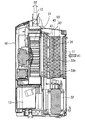
- FIG. 2 is a cross-sectional view of the dehumidifier 1 of the first embodiment.
- FIG. 2 shows a cross-section at the position AA in FIG.
- FIG. 2 shows an internal configuration of the dehumidifier 1 according to the first embodiment.
- the dehumidifier 1 includes a housing 10.
- casing 10 is formed so that it can become independent.
- the housing 10 is formed with a suction port 11 and an air outlet 12.
- the suction port 11 is an opening for taking in air from the outside to the inside of the housing 10.
- the air outlet 12 is an opening for sending air from the inside of the housing 10 to the outside.
- the suction port 11 is formed on the back surface of the housing 10.
- the air outlet 12 is formed on the upper surface of the housing 10.
- the suction inlet 11 and the blower outlet 12 may be provided in arbitrary places.
- the suction port 11 may be formed on the side surface of the housing 10.
- the dehumidifier 1 in which the suction port 11 is formed at a portion other than the back surface of the housing 10 can be used in a state where the back surface of the housing 10 is in contact with or close to the wall.
- the dehumidifier 1 includes a blower fan 21 as an example of a blower.
- the blower fan 21 is housed inside the housing 10. Inside the housing 10, an air passage that leads from the suction port 11 to the air outlet 12 is formed. The blower fan 21 is disposed in this air path.
- the blower fan 21 is a device that takes air into the housing 10 and sends the taken air to the outside of the housing 10.
- the dehumidifier 1 includes an evaporator 31, a compressor 32, a first condenser 33a, and a second condenser 33b.
- the evaporator 31, the compressor 32, the 1st condenser 33a, and the 2nd condenser 33b are accommodated in the inside of the housing
- the dehumidifier 1 includes dehumidifying means.
- the dehumidifying means is for removing moisture in the air.
- the dehumidifying means is constituted by a heat medium circuit.
- the heat medium circuit is a circuit in which the heat medium circulates.
- FIG. 3 is a diagram schematically illustrating the heat medium circuit according to the first embodiment. As shown in FIG. 3, the heat medium circuit of the present embodiment is formed by an evaporator 31, a compressor 32, a first condenser 33 a, a second condenser 33 b, and a decompression device 34.
- a heat medium flows through the evaporator 31, the compressor 32, the first condenser 33a, the second condenser 33b, and the decompression device 34.
- the evaporator 31, the compressor 32, the first condenser 33 a, the second condenser 33 b, and the decompression device 34 are connected in a ring shape through a pipe through which the heat medium flows.
- the evaporator 31, the first condenser 33a and the second condenser 33b are heat exchangers for performing heat exchange between the heat medium and air.
- the compressor 32 is a device that compresses the heat medium.
- the decompression device 34 is a device that decompresses the heat medium.
- the decompression device 34 is, for example, an expansion valve or a capillary tube.
- the evaporator 31, the compressor 32, the first condenser 33a, the second condenser 33b, and the decompression device 34 have an inlet and an outlet for the heat medium, respectively.
- the outlet of the evaporator 31 is connected to the inlet of the compressor 32.
- the heat medium that has passed through the evaporator 31 flows into the compressor 32.
- the compressor 32 compresses the heat medium that has flowed into the compressor 32.
- the heat medium compressed by the compressor 32 flows out from the outlet of the compressor 32.
- the outlet of the compressor 32 is connected to the inlet of the second condenser 33b.
- the outlet of the second condenser 33b is connected to the inlet of the first condenser 33a.
- the heat medium compressed by the compressor 32 flows through the first condenser 33a and the second condenser 33b.
- the outlet of the first condenser 33a is connected to the inlet of the decompression device 34.
- the heat medium that has passed through the first condenser 33 a and the second condenser 33 b flows into the decompression device 34.
- the decompression device 34 decompresses the heat medium flowing into the decompression device 34.
- the heat medium decompressed by the decompression device 34 expands.
- the outlet of the decompression device 34 is connected to the inlet of the evaporator 31.
- a heat medium decompressed by the decompression device 34 flows into the evaporator 31.
- the heat medium sequentially passes through the evaporator 31, the compressor 32, the second condenser 33b, the first condenser 33a, and the decompression device 34.
- the heat medium that has passed through the decompression device 34 flows through the evaporator 31 again.
- the heat medium circulates in the heat medium circuit in this way. Note that the connection order of the first condenser 33a and the second condenser 33b in the heat medium circuit may be reversed.
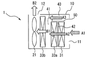
- FIG. 4 is a diagram schematically showing an air path inside the housing of the first embodiment.
- FIG. 4 corresponds to a schematic view of a part of the cross-sectional view of FIG.
- casing 10 and the said air path is demonstrated in detail.
- the evaporator 31, the first condenser 33a, and the second condenser 33b that form the heat medium circuit are arranged in an air path that leads from the suction port 11 to the blowout port 12, as shown in FIGS.
- the evaporator 31, the first condenser 33 a and the second condenser 33 b are disposed between the blower fan 21 and the suction port 11.
- the second condenser 33b is arranged on the upstream side of the blower fan 21 in the air passage that leads from the suction port 11 to the blowout port 12.
- the first condenser 33a is disposed on the upstream side of the second condenser 33b in the air passage leading from the suction port 11 to the blower outlet 12.
- the first condenser 33a and the second condenser 33b are arranged side by side.
- the mixing space 41 is formed in the housing 10 between the first condenser 33a and the second condenser 33b.
- the mixing space 41 is formed upstream of the second condenser 33 b in the air path that leads from the suction port 11 to the blower outlet 12.
- the air path leading from the suction port 11 to the air outlet 12 includes a first air path and a second air path.
- the first air path and the second air path are formed inside the housing 10.
- the first air passage is formed so that a part of the air taken into the housing 10 by the blower fan 21 is sent to the mixing space 41 through the evaporator 31 and the first condenser 33a in order. It is.
- the second air passage is formed so that a part of the air taken into the housing 10 by the blower fan 21 is sent to the mixing space 41 without passing through the evaporator 31 and the first condenser 33a. It is.
- a dehumidifying air passage 42 which is an example of a first air passage, is formed inside the housing 10 of the present embodiment.
- a bypass air passage 43 which is an example of a second air passage, is formed inside the housing 10 of the present embodiment.
- the dehumidifying air passage 42 and the bypass air passage 43 are air passages that lead from the suction port 11 to the mixing space 41, respectively.
- the dehumidifying air passage 42 is formed so that a part of the air taken into the housing 10 by the blower fan 21 passes through the evaporator 31, the first condenser 33a, and the second condenser 33b in order.
- the evaporator 31 and the first condenser 33a are disposed in the dehumidifying air passage 42.
- the dehumidifying air passage 42 extends from the suction port 11 to the mixing space 41 via the evaporator 31 and the first condenser 33a.
- the bypass air passage 43 is formed such that a part of the air taken into the housing 10 by the blower fan 21 passes through the second condenser 33b without passing through the evaporator 31 and the first condenser 33a. .
- the bypass air passage 43 is formed so as to bypass the evaporator 31 and the first condenser 33a.
- the bypass air passage 43 reaches the mixing space 41 from the suction port 11 without passing through the evaporator 31 and the first condenser 33a.
- the dehumidifying air passage 42 that is an example of the first air passage and the bypass air passage 43 that is an example of the second air passage are formed by an arbitrary method.
- a partition member 50 is provided inside the housing 10.
- the partition member 50 is a member that separates the dehumidifying air passage 42 and the bypass air passage 43.
- the partition member 50 has a flat plate shape, for example.
- the partition member 50 is provided above the evaporator 31 and the first condenser 33a as shown in FIGS.
- the dehumidifying air passage 42 is formed below the partition member 50.
- the bypass air passage 43 is formed above the partition member 50. In the present embodiment, the bypass air passage 43 is formed above the evaporator 31 and the first condenser 33a.
- the dehumidifying air passage 42 and the bypass air passage 43 of the present embodiment are formed by the housing 10 and the partition member 50.
- casing 10 and the partition member 50 may be formed integrally.
- the dehumidification air path 42 and the bypass air path 43 should just be formed by arbitrary methods as mentioned above.
- the partition member 50 may not be provided inside the housing 10. Further, the dehumidifying air passage 42 and the bypass air passage 43 may be formed by a member different from the housing 10 and the partition member 50.
- FIGS. 2 and 4 indicate the flow of air when the dehumidifier 1 is operating.
- the dehumidifier 1 operates when the blower fan 21 rotates. As described above, the dehumidifier 1 is used indoors, for example. When the blower fan 21 rotates, an air flow from the inlet 11 toward the outlet 12 is generated inside the housing 10. By generating an air flow by the blower fan 21, indoor air A ⁇ b> 1 is taken into the housing 10 from the suction port 11.
- the air A ⁇ b> 1 taken into the inside of the housing 10 branches into a dehumidifying air passage 42 and a bypass air passage 43.
- the air A2 that is a part of the air A1 is guided to the dehumidifying air passage 42.
- the air A3 which is a part of the air A1 is guided to the bypass air passage 43.
- the air A3 is a portion other than the air A2 guided to the dehumidifying air passage 42 among the air A1 taken into the housing 10.
- the air A2 guided to the dehumidifying air passage 42 passes through the evaporator 31.
- Heat exchange is performed between the air A ⁇ b> 2 passing through the evaporator 31 and the heat medium flowing through the evaporator 31.
- the heat medium depressurized by the decompression device 34 flows through the evaporator 31.
- a heat medium having a temperature lower than that of the air A ⁇ b> 1 taken into the inside of the housing 10 flows through the evaporator 31.
- the heat medium flowing through the evaporator 31 absorbs heat from the air A ⁇ b> 2 passing through the evaporator 31.
- the air A2 passing through the evaporator 31 is absorbed by the heat medium flowing through the evaporator 31.
- the air A2 passing through the evaporator 31 is cooled by the heat medium flowing through the evaporator 31.
- condensation occurs. That is, moisture contained in the air A2 is condensed.
- the condensed moisture is removed from the air A2.
- the moisture removed from the air A2 is stored, for example, in a water storage tank 13 provided inside the housing 10.
- the air A2 from which moisture has been removed by the evaporator 31 passes through the first condenser 33a. Heat exchange is performed between the air A2 passing through the first condenser 33a and the heat medium flowing through the first condenser 33a. The heat medium flowing through the first condenser 33a is cooled by the air A2 that passes through the first condenser 33a.
- the air A2 passing through the first condenser 33a is heated by the heat medium flowing through the first condenser 33a.
- the air A2 that has passed through the first condenser 33a reaches the mixing space 41.
- the air A2 guided to the dehumidifying air passage 42 is sent to the mixing space 41 through the evaporator 31 and the first condenser 33a.
- the air A3 guided to the bypass air passage 43 is sent to the mixing space 41 without passing through the evaporator 31 and the first condenser 33a as shown in FIG.
- the air A2 that has passed through the dehumidifying air passage 42 and the air A3 that has passed through the bypass air passage 43 are sent to the mixing space 41.
- the air A2 that has passed through the dehumidifying air passage 42 and the air A3 that has passed through the bypass air passage 43 are mixed.
- the mixed air B1 is generated.
- the mixed air B1 passes through the second condenser 33b. Heat exchange is performed between the mixed air B1 passing through the second condenser 33b and the heat medium flowing through the second condenser 33b.
- the heat medium flowing through the second condenser 33b is cooled by the mixed air B1 passing through the second condenser 33b.
- the mixed air B1 passing through the second condenser 33b is heated by the heat medium flowing through the second condenser 33b.
- Dry air B2 is produced
- the dry air B2 is air that is in a dry state than the indoor air A1.
- the dry air B2 passes through the blower fan 21.
- the dry air B ⁇ b> 2 that has passed through the blower fan 21 is sent out of the housing 10 from the air outlet 12. In this way, the dehumidifier 1 supplies the dry air B2 to the outside of the dehumidifier 1.
- the dehumidifier 1 of the present embodiment is configured such that a part of the air taken into the housing 10 passes through the evaporator 31, the first condenser 33a, and the second condenser 33b in order.
- the dehumidifier 1 is configured such that a part of the air taken into the housing 10 passes through the second condenser 33b without passing through the evaporator 31 and the first condenser 33a. If it is dehumidifier 1 of this Embodiment, with the above-mentioned composition, it is possible to make the air volume of air passing through evaporator 31 and the air volume of air passing through second condenser 33b each appropriate. Become.
- a mixed space 41 is formed inside the housing 10.
- the air A2 that has passed through the dehumidifying air passage 42 and the air A3 that has passed through the bypass air passage 43 are mixed to generate mixed air B1.
- the mixed air B1 having a more appropriate temperature can be passed through the second condenser 33b.
- the air volume of the mixed air B1 passing through the second condenser 33b can be made more appropriate.
- the heat medium flowing through the second condenser 33b is efficiently cooled by the mixed air B1. If it is this Embodiment, a heat carrier will be cooled efficiently and the efficiency of the heat exchange in the 2nd condenser 33b will become more favorable.
- the evaporator 31, the first condenser 33a, and the second condenser 33b in the above embodiment may be, for example, flat.
- the flat evaporator 31 and the first condenser 33a are arranged so that the surface having the maximum area is orthogonal to the flow direction of the air A2.
- the flat evaporator 31 and the first condenser 33a are arranged in parallel to each other as an example.
- the flat second condenser 33b may be arranged in parallel to the flat evaporator 31 and the first condenser 33a as an example.
- the second condenser 33b is separated from the first condenser 33a by a certain distance in one direction.
- the first condenser 33a is separated from the second condenser 33b by a fixed distance opposite to the one-side direction.
- the interval between the first condenser 33a and the second condenser 33b may be formed larger than the interval between the evaporator 31 and the first condenser 33a.
- the dimension along one side of the gap between the first condenser 33a and the second condenser 33b is larger than the dimension along one side of the gap between the evaporator 31 and the first condenser 33a. May be.
- the mixing space 41 may be formed wider than the gap formed between the evaporator 31 and the first condenser 33a.
- the mixing space 41 By forming the mixing space 41 wider, the air A2 and the air A3 are more uniformly mixed in the mixing space 41. By forming the mixing space 41 wider, the temperature distribution of the mixed air B1 becomes uniform. As the temperature distribution of the mixed air B1 becomes uniform, the heat medium flowing through the second condenser 33b is efficiently cooled by the mixed air B1. Thereby, the efficiency of heat exchange in the second condenser 33b becomes better.
- the dry air B2 having a more appropriate temperature is blown out from the outlet 12. According to the present embodiment, it is possible to prevent excessively cold air or excessively hot air from being blown out. According to this Embodiment, the discomfort of the user of the dehumidifier 1 is reduced more.
- the mixed air B1 passes through the second condenser 33b.
- the mixed air B ⁇ b> 1 is a combination of the air A ⁇ b> 2 that has passed through the dehumidifying air passage 42 and the air A ⁇ b> 3 that has passed through the bypass air passage 43.
- the interior of the housing 10 may be configured such that the air volume of the mixed air B1 passing through the second condenser 33b is larger than the air volume of the air A2 passing through the evaporator 31 in the dehumidifying air passage 42.
- the inside of the housing 10 may be configured such that all of the mixed air B1 in which the air A2 and the air A3 merge together passes through the second condenser 33b.
- an opening for taking air into the housing 10 may be separately formed in the housing 10.
- the opening is formed so that the air volume of the air passing through the second condenser 33b is larger than the air volume of the air passing through the evaporator 31. According to this configuration, the performance of the evaporator 31 and the performance of the second condenser 33b can be easily improved.
- the first condenser 33a may be disposed in the bypass air passage 43, for example. By providing the first condenser 33a in the bypass air passage 43, the dehumidifier 1 can be made more compact.
- the size of the first condenser 33a may be different from the size of the second condenser 33b.
- the temperature of the air A2 that has passed through the dehumidifying air passage 42 and the temperature of the dry air B2 that passes through the second condenser 33b and is sent out from the outlet 12 can be made more appropriate.
- the second condenser 33b may be formed larger than the evaporator 31 and the first condenser 33a, for example. Accordingly, for example, the bypass air passage 43 can be more easily formed inside the housing 10 without requiring the partition member 50 or the like.
- the evaporator 31, the first condenser 33a, and the second condenser 33b may have the same size.
- the bypass air passage 43 may be formed by arranging the evaporator 31, the first condenser 33 a, and the second condenser 33 b having the same size so as to be shifted from each other.
- the upper end of the second condenser 33b may be above the upper end of the first condenser 33a in a state where the housing 10 is placed on a horizontal plane.
- the bypass air passage 43 can be disposed above the evaporator 31 and the first condenser 33a.
- the bypass air passage 43 disposed above the evaporator 31 and the first condenser 33a is mixed from, for example, the suction port 11 without using a U-shaped joint attached to the evaporator 31 and the first condenser 33a.
- the space 41 is reached.
- a bypass air passage 43 disposed above the evaporator 31 and the first condenser 33a is a pipe connecting the evaporator 31, the compressor 32, the first condenser 33a, the second condenser 33b, and the pressure reducing device 34. It reaches from the inlet 11 to the mixing space 41 without going through. By eliminating the obstacle in the bypass air passage 43, it becomes easier to set the air amount of the air A3 flowing through the bypass air passage 43 to an appropriate amount.
- the dehumidifier 1 of said embodiment is comprised so that the temperature of the air A2 which passed the dehumidification air path 42 may become the same or higher with respect to the temperature of the air A3 which passed the bypass air path 43 as an example. Is done. For example, when the temperature of the air A2 is lower than that of the air A3, the temperature of the air A2 in the mixing space 41 increases as the air A2 is mixed with the air A3. On the other hand, in the above embodiment, the temperature of the air A2 can be lowered by the air A3 in the mixing space 41. Thereby, it becomes possible to produce the mixed air B1 having a lower temperature. By passing the cooler mixed air B1 through the second condenser 33b, the heat medium in the second condenser 33b is cooled more efficiently. If it is said embodiment, the efficiency of the heat exchange in the 2nd condenser 33b can be improved.
- FIG. 5 is a diagram illustrating a first modification of the dehumidifier 1 according to the first embodiment.
- FIG. 5 schematically shows the internal structure of the housing 10 in this modification.
- FIG. 5 shows a cross-section at the BB position in FIG.
- the lateral width of the second condenser 33 b may be wider than the lateral width of the first condenser 33 a in a state where the housing 10 is placed on a horizontal plane.
- the horizontal width of the second condenser 33b is the dimension of the second condenser 33b in the direction perpendicular to the flow direction and the vertical direction of the mixed air B1 passing through the second condenser 33b.
- the lateral width of the first condenser 33a is the dimension of the first condenser 33a in the direction perpendicular to the flow direction and the vertical direction of the air A2 passing through the first condenser 33a.
- the bypass air passage 43 can be formed more easily. Further, the bypass air passage 43 is formed on the left side and the right side of the evaporator 31 and the first condenser 33a, for example, as shown in FIG. Thereby, the air A3 that has passed through the bypass air passage 43 is guided to the mixing space 41 more efficiently. Moreover, when the second condenser 33b becomes larger, the performance of the second condenser 33b becomes better.
- FIG. 6 is a diagram illustrating a second modification of the dehumidifier 1 according to the first embodiment.
- FIG. 6 is a diagram corresponding to FIG. 4 in the above embodiment.
- the dehumidifier 1 may include a plurality of second condensers 33b.
- the heat medium circuit which comprises the dehumidification means of the dehumidifier 1
- a heat medium is condensed more efficiently. If it is this modification, the energy efficiency of the dehumidifier 1 becomes better.
- one size of the plurality of second condensers 33b may be different from another size of the plurality of second condensers 33b.
- FIG. 7 is a diagram illustrating a third modification of the dehumidifier 1 according to the first embodiment.
- the housing 10 may be formed with a first opening 11 a and a second opening 11 b instead of the suction port 11.
- the 1st opening 11a is formed in the back surface of the housing
- the second opening 11b is formed on the upper surface of the housing 10, for example.
- the first opening 11 a and the second opening 11 b are openings for taking in air from the outside to the inside of the housing 10. According to this modification, since there are a plurality of openings for taking in air from the outside to the inside of the housing 10, the amount of air passing through the second condenser 33b can be increased.
- the air taken in from the first opening 11a corresponds to the air A2 in each drawing of the present embodiment.
- the air A2 taken in from the first opening 11a passes through the evaporator 31 and the first condenser 33a in order.
- the second opening 11b is formed so that the air A3 taken in from the second opening 11b is sent to the mixing space 41 without passing through the evaporator 31 and the first condenser 33a.
- the positions of the second openings 11b in the horizontal direction are the first condenser 33a, the second condenser 33b, and the like.
- the air volume passing through the evaporator 31 and the air volume passing through the second condenser 33 b are set to appropriate amounts, as in the above-described embodiment and each modified example. It becomes possible. Further, the heat medium is efficiently cooled, and the efficiency of heat exchange in the second condenser 33b becomes better.
- the contact area between the mixed air B1 and the second condenser 33b may be larger than the contact area between the air A2 and the first condenser 33a.
- the interior of the housing 10 may be configured in this way. According to this configuration, heat exchange between the heat medium and the mixed air B1 in the second condenser 33b is more effectively performed.
- the dehumidifier according to the present invention is used, for example, for drying an arbitrary object.
Landscapes
- Engineering & Computer Science (AREA)
- Physics & Mathematics (AREA)
- Mechanical Engineering (AREA)
- Thermal Sciences (AREA)
- General Engineering & Computer Science (AREA)
- Chemical & Material Sciences (AREA)
- Analytical Chemistry (AREA)
- General Chemical & Material Sciences (AREA)
- Oil, Petroleum & Natural Gas (AREA)
- Chemical Kinetics & Catalysis (AREA)
- Drying Of Gases (AREA)
Abstract
除湿機(1)は、蒸発器(31)、第1凝縮器(33a)、第2凝縮器(33b)、筐体(10)および送風ファン(21)を備える。筐体(10)の内部には、第1凝縮器(33a)と第2凝縮器(33b)との間に混合空間(41)が形成される。送風ファン(21)によって筐体(10)の内部に取り込まれた空気の一部は、蒸発器(31)および第1凝縮器(33a)を順に通って混合空間(41)へ送られる。送風ファン(21)によって筐体(10)の内部に取り込まれた空気の一部は、蒸発器(31)及び第1凝縮器(33a)を介さずに混合空間(41)へ送られる。
Description
本発明は、除湿機に関するものである。
特許文献1に、除湿装置が記載されている。この除湿装置は、圧縮機、凝縮器、減圧装置および蒸発器を備える。特許文献1に記載された除湿装置は、圧縮機、凝縮器、減圧装置および蒸発器によって構成された冷凍サイクルによって、空気を除湿する。
特許文献1に記載された除湿装置の内部には、除湿風路と放熱風路とが独立して形成されている。この除湿風路には、蒸発器と凝縮器の一部とが配置される。また、放熱風路には、凝縮器の一部が配置されている。放熱風路は、蒸発器を通過しない風路である。これにより、特許文献1に記載された除湿装置であれば、蒸発器を通過する空気の風量と凝縮器を通過する空気の風量とを、それぞれ、異なる量にすることができる。
上記の特許文献1において、凝縮器には、蒸発器を通過して熱交換された空気と蒸発器によって熱交換されていない空気とが別々に通過する。すなわち、凝縮器には、温度分布のばらつきが大きい空気が通過する。このため、当該凝縮器では、空気と熱媒体との間での熱交換が効率よく行われない。
本発明は、上記のような課題を解決するためになされたものである。本発明の目的は、蒸発器を通過する空気の風量と凝縮器を通過する空気の風量とを適切な量にすることができ、且つ、当該凝縮器における熱交換をより効率よく行うことができる除湿機を得ることである。
本発明に係る除湿機は、熱媒体が通過する蒸発器と、蒸発器を通過した熱媒体を圧縮する圧縮機と、圧縮機によって圧縮された熱媒体が通過する第1凝縮器と、圧縮機によって圧縮された熱媒体が通過する第2凝縮器と、筐体と、送風手段と、を備える。筐体は、蒸発器、圧縮機、第1凝縮器及び第2凝縮器を内部に収容する。送風手段は、筐体の内部に空気を取り込み、取り込んだ空気を筐体の外部へ送る。筐体の内部には、第1凝縮器と第2凝縮器との間に混合空間が形成される。送風手段によって筐体の内部に取り込まれた空気の一部は、蒸発器および第1凝縮器を順に通って混合空間へ送られる。送風手段によって筐体の内部に取り込まれた空気の一部は、蒸発器及び第1凝縮器を介さずに混合空間へ送られる。
本発明に係る除湿機は、蒸発器、第1凝縮器、第2凝縮器、筐体および送風手段を備える。筐体の内部には、第1凝縮器と第2凝縮器との間に混合空間が形成される。送風手段によって筐体の内部に取り込まれた空気の一部は、蒸発器および第1凝縮器を順に通って混合空間へ送られる。送風手段によって筐体の内部に取り込まれた空気の一部は、蒸発器及び第1凝縮器を介さずに混合空間へ送られる。このため、本発明によれば、蒸発器を通過する空気の風量と凝縮器を通過する空気の風量とを適切な量にすることができ、且つ、当該凝縮器における熱交換をより効率よく行うことができる除湿機が得られる。
以下、添付の図面を参照して、実施の形態について説明する。各図における同一の符号は、同一の部分または相当する部分を示す。また、本開示では、重複する説明については適宜に簡略化または省略する。なお、本開示は、以下の各実施の形態で説明する構成のうち、組み合わせ可能な構成のあらゆる組み合わせを含み得るものである。
実施の形態1.
図1は、実施の形態1の除湿機1の正面図である。図1は、除湿機1の外観を示している。除湿機1は、例えば、室内の湿度を低下させることを目的として使用される。図2は、実施の形態1の除湿機1の断面図である。図2は、図1におけるA-A位置での断面を示す。図2は、実施の形態1の除湿機1の内部の構成を示している。
図1は、実施の形態1の除湿機1の正面図である。図1は、除湿機1の外観を示している。除湿機1は、例えば、室内の湿度を低下させることを目的として使用される。図2は、実施の形態1の除湿機1の断面図である。図2は、図1におけるA-A位置での断面を示す。図2は、実施の形態1の除湿機1の内部の構成を示している。
図1および図2に示すように、除湿機1は、筐体10を備える。筐体10は、自立可能に形成されている。筐体10には、吸込口11および吹出口12が形成されている。吸込口11は、筐体10の外部から内部へ空気を取り込むための開口である。吹出口12は、筐体10の内部から外部へ空気を送り出すための開口である。
本実施の形態において、吸込口11は、筐体10の背面に形成されている。吹出口12は、筐体10の上面に形成されている。なお、吸込口11および吹出口12は、任意の場所に設けられてよい。例えば、吸込口11は、筐体10の側面に形成されてもよい。吸込口11が筐体10の背面でない部分に形成された除湿機1は、当該筐体10の背面が壁に接触または近接した状態で使用可能となる。
除湿機1は、送風手段の一例として、送風ファン21を備える。送風ファン21は、筐体10の内部に収容される。筐体10の内部には、吸込口11から吹出口12へと通じる風路が形成されている。送風ファン21は、この風路に配置されている。送風ファン21は、筐体10の内部に空気を取り込み、取り込んだ空気を筐体10の外部へ送る装置である。
また、除湿機1は、蒸発器31、圧縮機32、第1凝縮器33aおよび第2凝縮器33bを備える。蒸発器31、圧縮機32、第1凝縮器33aおよび第2凝縮器33bは、図2に示すように、筐体10の内部に収容される。
除湿機1は、除湿手段を備える。除湿手段とは、空気中の水分を除去するためのものである。除湿手段は、熱媒体回路によって構成される。熱媒体回路とは、熱媒体が循環する回路である。図3は、実施の形態1の熱媒体回路を模式的に示す図である。本実施の形態の熱媒体回路は、図3に示すように、蒸発器31、圧縮機32、第1凝縮器33a、第2凝縮器33bおよび減圧装置34によって形成される。
蒸発器31、圧縮機32、第1凝縮器33a、第2凝縮器33bおよび減圧装置34には、熱媒体が流れる。蒸発器31、圧縮機32、第1凝縮器33a、第2凝縮器33bおよび減圧装置34は、熱媒体が流れる配管を介し、環状に接続される。
蒸発器31、第1凝縮器33aおよび第2凝縮器33bは、熱媒体と空気との間での熱交換を行うための熱交換器である。圧縮機32は、熱媒体を圧縮させる装置である。減圧装置34は、熱媒体を減圧させる装置である。減圧装置34は、例えば、膨張弁またはキャピラリーチューブ等である。
蒸発器31、圧縮機32、第1凝縮器33a、第2凝縮器33bおよび減圧装置34は、それぞれ、熱媒体の入口および出口を有している。蒸発器31の出口は、圧縮機32の入口に接続される。圧縮機32には、蒸発器31を通過した熱媒体が流入する。圧縮機32は、当該圧縮機32に流入した熱媒体を圧縮する。圧縮機32によって圧縮された熱媒体は、当該圧縮機32の出口から流出する。
圧縮機32の出口は、第2凝縮器33bの入口に接続される。第2凝縮器33bの出口は、第1凝縮器33aの入口に接続される。第1凝縮器33aおよび第2凝縮器33bには、圧縮機32によって圧縮された熱媒体が流れる。
第1凝縮器33aの出口は、減圧装置34の入口に接続される。減圧装置34には、第1凝縮器33aおよび第2凝縮器33bを通過した熱媒体が流入する。減圧装置34は、当該減圧装置34に流入した熱媒体を減圧させる。減圧装置34によって減圧した熱媒体は、膨張する。
減圧装置34の出口は、蒸発器31の入口に接続される。蒸発器31には、減圧装置34によって減圧した熱媒体が流入する。本実施の形態において熱媒体は、蒸発器31、圧縮機32、第2凝縮器33b、第1凝縮器33aおよび減圧装置34を順に通過する。減圧装置34を通過した熱媒体は、再び蒸発器31を流れる。本実施の形態において熱媒体は、このように熱媒体回路を循環する。なお、熱媒体回路における第1凝縮器33aおよび第2凝縮器33bの接続順序は、逆でもよい。
図4は、実施の形態1の筐体の内部の風路を模式的に示す図である。図4は、図2の断面図の一部を模式的に示したものに相当する。図2および図4を参照して、筐体10の内部に形成された風路および当該風路に配置された各部品の構成について、より詳細に説明する。
熱媒体回路を形成する蒸発器31、第1凝縮器33aおよび第2凝縮器33bは、図2および図4に示すように、吸込口11から吹出口12へと通じる風路に配置される。本実施の形態において、蒸発器31、第1凝縮器33aおよび第2凝縮器33bは、送風ファン21と吸込口11との間に配置される。
第2凝縮器33bは、吸込口11から吹出口12へと通じる風路において、送風ファン21の上流側に配置される。また、第1凝縮器33aは、吸込口11から吹出口12へと通じる風路において、第2凝縮器33bの上流側に配置される。本実施の形態において第1凝縮器33aと第2凝縮器33bとは、隣り合った状態で並べられている。
第1凝縮器33aと第2凝縮器33bとの間には、予め設定された寸法の隙間がある。この隙間を、本開示では、混合空間41と称する。すなわち、筐体10の内部には、第1凝縮器33aと第2凝縮器33bとの間に、混合空間41が形成されている。混合空間41は、吸込口11から吹出口12へと通じる風路において、第2凝縮器33bの上流に形成される。
吸込口11から吹出口12へと通じる風路には、第1風路および第2風路が含まれる。換言すると、筐体10の内部には、この第1風路および第2風路が形成される。第1風路は、送風ファン21によって筐体10の内部に取り込まれた空気の一部が蒸発器31および第1凝縮器33aを順に通って混合空間41へ送られるように形成された風路である。第2風路は、送風ファン21によって筐体10の内部に取り込まれた空気の一部が蒸発器31及び第1凝縮器33aを介さずに混合空間41へ送られるように形成された風路である。
本実施の形態の筐体10の内部には、第1風路の一例である除湿風路42が形成される。また、本実施の形態の筐体10の内部には、第2風路の一例であるバイパス風路43が形成される。図2および図4に示すように、除湿風路42およびバイパス風路43は、それぞれ、吸込口11から混合空間41へと通じる風路である。
除湿風路42は、送風ファン21によって筐体10の内部に取り込まれた空気の一部が蒸発器31と第1凝縮器33aと第2凝縮器33bとを順に通過するように形成される。蒸発器31および第1凝縮器33aは、この除湿風路42に配置されている。除湿風路42は、吸込口11から、蒸発器31および第1凝縮器33aを介して、混合空間41へと至る。
バイパス風路43は、送風ファン21によって筐体10の内部に取り込まれた空気の一部が蒸発器31および第1凝縮器33aを介さずに第2凝縮器33bを通過するように形成される。バイパス風路43は、蒸発器31および第1凝縮器33aを迂回するように形成される。バイパス風路43は、吸込口11から、蒸発器31および第1凝縮器33aを介さずに、混合空間41へと至る。
第1風路の一例である除湿風路42と第2風路の一例であるバイパス風路43とは、任意の方法によって形成される。一例として、筐体10の内部には、仕切部材50が設けられる。仕切部材50は、除湿風路42とバイパス風路43とを区切る部材である。仕切部材50は、例えば、平板状である。
本実施の形態において仕切部材50は、図2および図4に示すように、蒸発器31および第1凝縮器33aの上方に設けられる。除湿風路42は、この仕切部材50の下方に形成される。バイパス風路43は、仕切部材50の上方に形成される。本実施の形態においてバイパス風路43は、蒸発器31および第1凝縮器33aの上方に形成される。
本実施の形態の除湿風路42およびバイパス風路43は、筐体10と仕切部材50とによって形成されている。なお、筐体10と仕切部材50とは、一体的に形成されてもよい。また、除湿風路42およびバイパス風路43は、上述したように、任意の方法によって形成されればよい。筐体10の内部には、仕切部材50が設けられていなくてもよい。また、除湿風路42およびバイパス風路43は、筐体10および仕切部材50とは別の部材によって形成されてもよい。
次に、図2および図4を参照して、本実施の形態の除湿機1の動作について説明する。図2および図4における矢印は、除湿機1が動作している際の空気の流れを示している。
除湿機1は、送風ファン21が回転することによって動作する。上述したように、除湿機1は、例えば、室内で使用される。送風ファン21が回転すると、吸込口11から吹出口12へ向かう気流が筐体10の内部に発生する。送風ファン21によって気流が発生させられることにより、室内の空気A1が吸込口11から筐体10の内部へ取り込まれる。
筐体10の内部へ取り込まれた空気A1は、除湿風路42とバイパス風路43とに分岐する。空気A1の一部である空気A2は、除湿風路42へ導かれる。また、空気A1の一部である空気A3は、バイパス風路43へ導かれる。空気A3は、筐体10の内部へ取り込まれた空気A1のうち、除湿風路42へ導かれた空気A2以外の部分である。
除湿風路42へ導かれた空気A2は、蒸発器31を通過する。蒸発器31を通過する空気A2と当該蒸発器31を流れる熱媒体との間で熱交換が行われる。蒸発器31には、上述したように、減圧装置34によって減圧した熱媒体が流れる。蒸発器31には、筐体10の内部へ取り込まれた空気A1よりも低温の熱媒体が流れる。蒸発器31を流れる熱媒体は、当該蒸発器31を通過する空気A2から熱を吸収する。
蒸発器31を通過する空気A2は、当該蒸発器31を流れる熱媒体によって吸熱される。蒸発器31を通過する空気A2は、蒸発器31を流れる熱媒体によって冷却される。これにより、結露が発生する。すなわち、空気A2に含まれる水分が凝縮する。凝縮した水分は、空気A2から除去される。空気A2から除去された水分は、例えば、筐体10の内部に設けられた貯水タンク13に貯められる。
蒸発器31によって水分が除去された空気A2は、第1凝縮器33aを通過する。第1凝縮器33aを通過する空気A2と当該第1凝縮器33aを流れる熱媒体との間で熱交換が行われる。第1凝縮器33aを流れる熱媒体は、当該第1凝縮器33aを通過する空気A2によって冷却される。
第1凝縮器33aを通過する空気A2は、当該第1凝縮器33aを流れる熱媒体によって加熱される。第1凝縮器33aを通過した空気A2は、混合空間41へと至る。このように、除湿風路42へ導かれた空気A2は、蒸発器31および第1凝縮器33aを通って混合空間41へと送られる。
また、バイパス風路43へ導かれた空気A3は、図4に示すように、蒸発器31および第1凝縮器33aを通過することなく混合空間41へと送られる。混合空間41には、除湿風路42を通過した空気A2とバイパス風路43を通過した空気A3とが送られる。
混合空間41では、除湿風路42を通過した空気A2とバイパス風路43を通過した空気A3とが混合される。空気A2と空気A3とが混合されることによって、混合空気B1が生成される。混合空気B1は、図4に示すように、第2凝縮器33bを通過する。第2凝縮器33bを通過する混合空気B1と当該第2凝縮器33bを流れる熱媒体との間で熱交換が行われる。第2凝縮器33bを流れる熱媒体は、当該第2凝縮器33bを通過する混合空気B1によって冷却される。
第2凝縮器33bを通過する混合空気B1は、当該第2凝縮器33bを流れる熱媒体によって加熱される。混合空気B1が熱媒体によって加熱されることにより、乾燥空気B2が生成される。乾燥空気B2は、室内の空気A1よりも乾燥した状態の空気である。乾燥空気B2は、送風ファン21を通過する。送風ファン21を通過した乾燥空気B2は、吹出口12から、筐体10の外部へ送り出される。このようにして、除湿機1は、乾燥空気B2を当該除湿機1の外部へ供給する。
本実施の形態の除湿機1は、筐体10の内部に取り込まれた空気の一部が蒸発器31、第1凝縮器33aおよび第2凝縮器33bを順に通過するように構成されている。また、除湿機1は、筐体10の内部に取り込まれた空気の一部が蒸発器31および第1凝縮器33aを介さずに第2凝縮器33bを通過するように構成されている。本実施の形態の除湿機1であれば、上記の構成により、蒸発器31を通過する空気の風量と第2凝縮器33bを通過する空気の風量とをそれぞれ適切な量にすることが可能となる。
本実施の形態において、筐体10の内部には、混合空間41が形成されている。混合空間41では、除湿風路42を通過した空気A2とバイパス風路43を通過した空気A3とが混合されることによって、混合空気B1が生成される。本実施の形態であれば、除湿風路42を通過した空気A2の温度を上昇させることなく、第2凝縮器33bを通過する混合空気B1の風量を増やすことが可能となる。これにより、より適切な温度の混合空気B1を第2凝縮器33bに通過させることができる。また、第2凝縮器33bを通過する混合空気B1の風量をより適切にすることができる。第2凝縮器33bを流れる熱媒体は混合空気B1によって効率よく冷却される。本実施の形態であれば、熱媒体が効率よく冷却され、第2凝縮器33bにおける熱交換の効率がより良好になる。
上記の実施の形態における蒸発器31、第1凝縮器33aおよび第2凝縮器33bは、例えば、平板状であってもよい。平板状の蒸発器31および第1凝縮器33aは、最大面積を有する面が、空気A2の流れの向きに直交するように配置される。平板状の蒸発器31および第1凝縮器33aは、一例として、互いに平行に配置される。また、平板状の第2凝縮器33bは、一例として、平板状の蒸発器31および第1凝縮器33aに対して平行に配置されてもよい。
第2凝縮器33bは、第1凝縮器33aから一側方向に一定の距離だけ離れている。第1凝縮器33aは、第2凝縮器33bから上記一側方向の反対に一定の距離だけ離れている。第1凝縮器33aと第2凝縮器33bとの間隔は、蒸発器31と第1凝縮器33aとの間隔に比べて大きく形成されてもよい。第1凝縮器33aと第2凝縮器33bとの間の隙間の一側方向に沿った寸法は、蒸発器31と第1凝縮器33aとの間の隙間の一側方向に沿った寸法より大きくてもよい。混合空間41は、蒸発器31と第1凝縮器33aとの間に形成された隙間よりも広く形成されてもよい。
混合空間41がより広く形成されることにより、当該混合空間41では、空気A2と空気A3とがより均一に混合される。混合空間41がより広く形成されることにより、混合空気B1の温度分布が均一になる。混合空気B1の温度分布が均一になることにより、第2凝縮器33bを流れる熱媒体は当該混合空気B1によって効率よく冷却される。これにより、第2凝縮器33bにおける熱交換の効率がより良好になる。
また、混合空間41で空気A2と空気A3とが混合されることによって、より適切な温度の乾燥空気B2が吹出口12から吹き出される。本実施の形態によれば、過度に低温な空気または過度に高温な空気が吹き出されることが防止される。本実施の形態によれば、除湿機1の使用者の不快感がより軽減される。
上記の実施の形態において、第2凝縮器33bには、混合空気B1が通過する。混合空気B1は、除湿風路42を通過した空気A2とバイパス風路43を通過した空気A3とが合流したものである。筐体10の内部は、第2凝縮器33bを通過する混合空気B1の風量が除湿風路42内の蒸発器31を通過する空気A2の風量よりも多くなるように構成されてもよい。例えば、筐体10の内部は、空気A2と空気A3とが合流した混合空気B1の全てが第2凝縮器33bを通過するように構成されてもよい。
これにより、蒸発器31を通過する空気の風量を増やさなくても、第2凝縮器33bを通過する空気の風量をより多くすることができる。第2凝縮器33bを通過する空気の風量がより多くなることにより、当該第2凝縮器33bにおける熱交換の効率がより良好になる。また、蒸発器31を通過する空気の風量が少なく維持されることにより、当該蒸発器31が空気を除湿する性能を良好な状態に保つことができる。
なお、筐体10には、吸込口11に加えて、当該筐体10の内部に空気を取り込む開口が別途形成されてもよい。この開口は、例えば、第2凝縮器33bを通過する空気の風量が蒸発器31を通過する空気の風量よりも多くなるように形成される。本構成によれば、蒸発器31の性能と第2凝縮器33bの性能とを、より容易に良好にすることができる。
第1凝縮器33aは、例えば、バイパス風路43に配置されてもよい。第1凝縮器33aがバイパス風路43に設けられることによって、除湿機1をよりコンパクトにすることができる。
図2及び図4に示すように、第1凝縮器33aの大きさは第2凝縮器33bの大きさと異なっていてもよい。これにより、除湿風路42を通過した空気A2の温度と第2凝縮器33bを通過して吹出口12から送り出される乾燥空気B2の温度とを、それぞれ、より適切な温度にすることが可能になる。また、第2凝縮器33bは、例えば、蒸発器31および第1凝縮器33aよりも大きく形成されてもよい。これにより、例えば仕切部材50等を必要とせずに、筐体10の内部にバイパス風路43をより容易に形成することが可能になる。
なお、蒸発器31、第1凝縮器33aおよび第2凝縮器33bは、互いに同程度の大きさであってもよい。バイパス風路43は、同程度の大きさの蒸発器31と第1凝縮器33aと第2凝縮器33bとが互いにずれた状態で配置されることによって、形成されてもよい。
また、図2および図4に示すように、筐体10が水平面に置かれた状態において、第2凝縮器33bの上端は、第1凝縮器33aの上端よりも上方にあってもよい。これにより、バイパス風路43を、蒸発器31および第1凝縮器33aの上方に配置可能となる。蒸発器31および第1凝縮器33aの上方に配置されたバイパス風路43は、例えば、蒸発器31および第1凝縮器33aに取り付けられたU字型の継手を介さずに吸込口11から混合空間41へと至る。また、蒸発器31および第1凝縮器33aの上方に配置されたバイパス風路43は、蒸発器31、圧縮機32、第1凝縮器33a、第2凝縮器33bおよび減圧装置34を接続する配管を介さずに吸込口11から混合空間41へと至る。バイパス風路43に障害物がなくなることにより、当該バイパス風路43を流れる空気A3の風量を適切な量にすることがより容易となる。
また、上記の実施の形態の除湿機1は、一例として、除湿風路42を通過した空気A2の温度がバイパス風路43を通過した空気A3の温度に対して同じもしくは高くなるように、構成される。例えば、空気A2の温度が空気A3より低温である場合、混合空間41において当該空気A2の温度は、当該空気A2が当該空気A3と混合されることで、上がる。これに対し、上記の実施の形態であれば、混合空間41において、空気A2の温度を空気A3によって低下させることが可能となる。これにより、より低温の混合空気B1を生成することが可能となる。より低温の混合空気B1が第2凝縮器33bを通過することで、当該第2凝縮器33b内の熱媒体がより効率よく冷却される。上記の実施の形態であれば、第2凝縮器33bにおける熱交換の効率をより良くすることができる。
図5は、実施の形態1の除湿機1の第1の変形例を示す図である。図5は、本変形例における筐体10の内部の構造を模式的に示している。図5は、図1におけるB-B位置での断面を示す。図5に示すように、筐体10が水平面に置かれた状態において、第2凝縮器33bの横幅は、第1凝縮器33aの横幅より広くてもよい。第2凝縮器33bの横幅とは、当該第2凝縮器33bを通過する混合空気B1の流れ方向及び鉛直方向に垂直な方向における当該第2凝縮器33bの寸法である。第1凝縮器33aの横幅とは、当該第1凝縮器33aを通過する空気A2の流れ方向及び鉛直方向に垂直な方向における当該第1凝縮器33aの寸法である。
第2凝縮器33bの横幅が第1凝縮器33aの横幅より広くなることにより、バイパス風路43をより容易に形成することができる。また、バイパス風路43は、例えば、図5に示すように、蒸発器31および第1凝縮器33aの左方及び右方に形成される。これにより、バイパス風路43を通過した空気A3は、より効率よく混合空間41へ導かれる。また、第2凝縮器33bがより大きくなることにより、当該第2凝縮器33bの性能はより良好になる。
また、図6は、実施の形態1の除湿機1の第2の変形例を示す図である。図6は、上記の実施の形態における図4に対応する図である。図6に示すように、除湿機1は、複数の第2凝縮器33bを備えていてもよい。これにより、除湿機1の除湿手段を構成する熱媒体回路において熱媒体がより効率よく凝縮される。本変形例であれば、除湿機1のエネルギー効率がより良好になる。また、図6に示すように、複数の第2凝縮器33bの1つの大きさは、当該複数の第2凝縮器33bの別の1つの大きさと異なっていてもよい。大きさの異なる第2凝縮器33bが筐体10内に配置されることにより、筐体10内の風路の設計の範囲がより広くなる。
図7は、実施の形態1の除湿機1の第3の変形例を示す図である。図7に示すように、筐体10には、吸込口11に代えて、第1開口11aおよび第2開口11bが形成されてもよい。第1開口11aは、例えば、筐体10の背面に形成される。第2開口11bは、例えば、筐体10の上面に形成される。第1開口11aおよび第2開口11bは、筐体10の外部から内部へ空気を取り込むための開口である。本変形例によれば、筐体10の外部から内部へ空気を取り込むための開口が複数あることによって、第2凝縮器33bを通過する空気の風量をより多くすることができる。
第1開口11aから取り込まれる空気は、本実施の形態の各図における空気A2に対応する。第1開口11aから取り込まれる空気A2は、蒸発器31および第1凝縮器33aを順に通過する。また、第2開口11bから取り込まれる空気は、本実施の形態の各図における空気A3に対応する。第2開口11bは、当該第2開口11bから取り込まれる空気A3が蒸発器31及び第1凝縮器33aを介さずに混合空間41へ送られるように形成される。例えば、蒸発器31と第1凝縮器33aと第2凝縮器33bとが水平方向に並んでいる場合、水平方向における第2開口11bの位置は、第1凝縮器33aと第2凝縮器33bとの間になる。図7に示す変形例においても、上記した実施の形態および各変形例と同様、蒸発器31を通過する空気の風量と第2凝縮器33bを通過する空気の風量とをそれぞれ適切な量にすることが可能となる。また、熱媒体が効率よく冷却され、第2凝縮器33bにおける熱交換の効率がより良好になる。
なお、上記の実施の形態及び各変形例において、混合空気B1と第2凝縮器33bとの接触面積は、空気A2と第1凝縮器33aとの接触面積よりも大きくてもよい。筐体10の内部は、このように構成されてもよい。本構成によれば、第2凝縮器33bにおける熱媒体と混合空気B1との熱交換がより効果的に行われる。
本発明に係る除湿機は、例えば、任意の対象物を乾燥させるために利用される。
1 除湿機、 10 筐体、 11 吸込口、 11a 第1開口、 11b 第2開口、 12 吹出口、 13 貯水タンク、 21 送風ファン、 31 蒸発器、 32 圧縮機、 33a 第1凝縮器、 33b 第2凝縮器、 34 減圧装置、 41 混合空間、 42 除湿風路、 43 バイパス風路、 50 仕切部材
Claims (8)
- 熱媒体が通過する蒸発器と、
前記蒸発器を通過した熱媒体を圧縮する圧縮機と、
前記圧縮機によって圧縮された熱媒体が通過する第1凝縮器と、
前記圧縮機によって圧縮された熱媒体が通過する第2凝縮器と、
前記蒸発器、前記圧縮機、前記第1凝縮器および前記第2凝縮器を内部に収容する筐体と、
前記筐体の内部に空気を取り込み、取り込んだ空気を前記筐体の外部へ送る送風手段と、
を備え、
前記筐体の内部には、前記第1凝縮器と前記第2凝縮器との間に混合空間が形成され、
前記送風手段によって前記筐体の内部に取り込まれた空気の一部は、前記蒸発器および前記第1凝縮器を順に通って前記混合空間へ送られ、
前記送風手段によって前記筐体の内部に取り込まれた空気の一部は、前記蒸発器および前記第1凝縮器を介さずに前記混合空間へ送られる除湿機。 - 前記筐体の内部には、前記送風手段によって前記筐体の内部に取り込まれた空気の一部が前記蒸発器および前記第1凝縮器を順に通って前記混合空間へ送られるように形成された第1風路と、前記送風手段によって前記筐体の内部に取り込まれた空気の一部が前記蒸発器および前記第1凝縮器を介さずに前記混合空間へ送られるように形成された第2風路と、が設けられている請求項1に記載の除湿機。
- 前記送風手段によって前記第2凝縮器を通過する空気の風量は、前記送風手段によって前記蒸発器を通過する空気の風量よりも多い請求項1または請求項2に記載の除湿機。
- 前記送風手段によって前記蒸発器および前記第1凝縮器を順に通って前記混合空間へ送られた空気の温度は、前記送風手段によって前記蒸発器および前記第1凝縮器を介さずに前記混合空間へ送られた空気の温度に対して、同じもしくは高い請求項1から請求項3の何れか1項に記載の除湿機。
- 前記第1凝縮器と前記第2凝縮器との間隔は、前記蒸発器と前記第1凝縮器との間隔に比べて大きい請求項1から請求項4の何れか1項に記載の除湿機。
- 前記送風手段によって前記第2凝縮器を通過する空気と前記第2凝縮器との接触面積は、前記送風手段によって前記第1凝縮器を通過する空気と前記第1凝縮器との接触面積よりも大きい請求項1から請求項5の何れか1項に記載の除湿機。
- 前記筐体が水平面に置かれた状態において、前記第2凝縮器の上端は、前記第1凝縮器の上端よりも上方にある請求項1から請求項6の何れか1項に記載の除湿機。
- 前記筐体が水平面に置かれた状態において、前記送風手段によって前記第2凝縮器を通過する空気の流れ方向及び鉛直方向に垂直な方向における前記第2凝縮器の寸法は、前記送風手段によって前記第1凝縮器を通過する空気の流れ方向及び鉛直方向に垂直な方向における前記第1凝縮器の寸法よりも大きい請求項1から請求項7の何れか1項に記載の除湿機。
Priority Applications (2)
| Application Number | Priority Date | Filing Date | Title |
|---|---|---|---|
| JP2019501025A JP6721102B2 (ja) | 2017-02-23 | 2017-10-06 | 除湿機 |
| CN201780078514.0A CN110337320B (zh) | 2017-02-23 | 2017-10-06 | 除湿机 |
Applications Claiming Priority (2)
| Application Number | Priority Date | Filing Date | Title |
|---|---|---|---|
| JP2017032301 | 2017-02-23 | ||
| JP2017-032301 | 2017-02-23 |
Publications (1)
| Publication Number | Publication Date |
|---|---|
| WO2018154836A1 true WO2018154836A1 (ja) | 2018-08-30 |
Family
ID=63254321
Family Applications (1)
| Application Number | Title | Priority Date | Filing Date |
|---|---|---|---|
| PCT/JP2017/036460 Ceased WO2018154836A1 (ja) | 2017-02-23 | 2017-10-06 | 除湿機 |
Country Status (4)
| Country | Link |
|---|---|
| JP (1) | JP6721102B2 (ja) |
| CN (1) | CN110337320B (ja) |
| TW (1) | TWI663366B (ja) |
| WO (1) | WO2018154836A1 (ja) |
Cited By (7)
| Publication number | Priority date | Publication date | Assignee | Title |
|---|---|---|---|---|
| JP2020121248A (ja) * | 2019-01-29 | 2020-08-13 | パナソニックIpマネジメント株式会社 | 除湿装置 |
| JP2021021525A (ja) * | 2019-07-26 | 2021-02-18 | 三菱電機株式会社 | 除湿機 |
| JP2022024603A (ja) * | 2020-07-28 | 2022-02-09 | 三菱電機株式会社 | 除湿装置 |
| CN115355573A (zh) * | 2022-08-25 | 2022-11-18 | 伊岛电器(宁波)有限公司 | 一种新型进风方式的除湿机 |
| WO2023276175A1 (ja) * | 2021-06-28 | 2023-01-05 | 三菱電機株式会社 | 除湿機 |
| JP2024080746A (ja) * | 2022-12-05 | 2024-06-17 | オリオン機械株式会社 | 圧縮空気除湿装置及び圧縮空気除湿装置ユニット |
| CN121408761A (zh) * | 2025-12-29 | 2026-01-27 | 大连理工大学 | 一种温湿度适用范围宽的精密空气调节装置及方法 |
Families Citing this family (3)
| Publication number | Priority date | Publication date | Assignee | Title |
|---|---|---|---|---|
| CN116368332B (zh) * | 2020-11-17 | 2025-06-10 | 三菱电机株式会社 | 除湿机 |
| JP7635884B2 (ja) * | 2022-05-11 | 2025-02-26 | 三菱電機株式会社 | 除湿機 |
| CN115978663A (zh) * | 2022-12-20 | 2023-04-18 | 青岛海尔空调器有限总公司 | 除湿机 |
Citations (4)
| Publication number | Priority date | Publication date | Assignee | Title |
|---|---|---|---|---|
| US7246503B1 (en) * | 2005-11-16 | 2007-07-24 | Bou-Matic Technologies Llc | Enhanced drying dehumidifier |
| JP2011092867A (ja) * | 2009-10-30 | 2011-05-12 | Panasonic Corp | 除湿装置 |
| JP2016055264A (ja) * | 2014-09-11 | 2016-04-21 | パナソニックIpマネジメント株式会社 | 除湿装置 |
| WO2016143060A1 (ja) * | 2015-03-10 | 2016-09-15 | 三菱電機株式会社 | 除湿装置 |
Family Cites Families (5)
| Publication number | Priority date | Publication date | Assignee | Title |
|---|---|---|---|---|
| JP2005233562A (ja) * | 2004-02-23 | 2005-09-02 | Chikayoshi Sato | 空気調和方法及び空気調和装置 |
| KR102200379B1 (ko) * | 2013-12-10 | 2021-01-08 | 엘지전자 주식회사 | 제습기 |
| KR102194676B1 (ko) * | 2013-12-10 | 2020-12-24 | 엘지전자 주식회사 | 제습기 |
| CN104019574B (zh) * | 2014-05-16 | 2017-10-31 | 浙江普林艾尔电器工业有限公司 | 一种低冷凝压力深度过冷高效除湿机 |
| CN205717593U (zh) * | 2016-06-16 | 2016-11-23 | 浙江欧伦电气有限公司 | 一种风机前置高温除湿机 |
-
2017
- 2017-10-06 WO PCT/JP2017/036460 patent/WO2018154836A1/ja not_active Ceased
- 2017-10-06 CN CN201780078514.0A patent/CN110337320B/zh active Active
- 2017-10-06 TW TW106134431A patent/TWI663366B/zh active
- 2017-10-06 JP JP2019501025A patent/JP6721102B2/ja active Active
Patent Citations (4)
| Publication number | Priority date | Publication date | Assignee | Title |
|---|---|---|---|---|
| US7246503B1 (en) * | 2005-11-16 | 2007-07-24 | Bou-Matic Technologies Llc | Enhanced drying dehumidifier |
| JP2011092867A (ja) * | 2009-10-30 | 2011-05-12 | Panasonic Corp | 除湿装置 |
| JP2016055264A (ja) * | 2014-09-11 | 2016-04-21 | パナソニックIpマネジメント株式会社 | 除湿装置 |
| WO2016143060A1 (ja) * | 2015-03-10 | 2016-09-15 | 三菱電機株式会社 | 除湿装置 |
Cited By (13)
| Publication number | Priority date | Publication date | Assignee | Title |
|---|---|---|---|---|
| JP2020121248A (ja) * | 2019-01-29 | 2020-08-13 | パナソニックIpマネジメント株式会社 | 除湿装置 |
| JP7316487B2 (ja) | 2019-01-29 | 2023-07-28 | パナソニックIpマネジメント株式会社 | 除湿装置 |
| JP2021021525A (ja) * | 2019-07-26 | 2021-02-18 | 三菱電機株式会社 | 除湿機 |
| JP7211299B2 (ja) | 2019-07-26 | 2023-01-24 | 三菱電機株式会社 | 除湿機 |
| JP7394722B2 (ja) | 2020-07-28 | 2023-12-08 | 三菱電機株式会社 | 除湿装置 |
| JP2022024603A (ja) * | 2020-07-28 | 2022-02-09 | 三菱電機株式会社 | 除湿装置 |
| WO2023276175A1 (ja) * | 2021-06-28 | 2023-01-05 | 三菱電機株式会社 | 除湿機 |
| JPWO2023276175A1 (ja) * | 2021-06-28 | 2023-01-05 | ||
| CN115355573A (zh) * | 2022-08-25 | 2022-11-18 | 伊岛电器(宁波)有限公司 | 一种新型进风方式的除湿机 |
| CN115355573B (zh) * | 2022-08-25 | 2024-02-23 | 伊岛电器(宁波)有限公司 | 一种新型进风方式的除湿机 |
| JP2024080746A (ja) * | 2022-12-05 | 2024-06-17 | オリオン機械株式会社 | 圧縮空気除湿装置及び圧縮空気除湿装置ユニット |
| JP7744021B2 (ja) | 2022-12-05 | 2025-09-25 | オリオン機械株式会社 | 圧縮空気除湿装置及び圧縮空気除湿装置ユニット |
| CN121408761A (zh) * | 2025-12-29 | 2026-01-27 | 大连理工大学 | 一种温湿度适用范围宽的精密空气调节装置及方法 |
Also Published As
| Publication number | Publication date |
|---|---|
| CN110337320A (zh) | 2019-10-15 |
| JP6721102B2 (ja) | 2020-07-08 |
| TWI663366B (zh) | 2019-06-21 |
| JPWO2018154836A1 (ja) | 2019-08-08 |
| CN110337320B (zh) | 2022-06-17 |
| TW201831840A (zh) | 2018-09-01 |
Similar Documents
| Publication | Publication Date | Title |
|---|---|---|
| JP6721102B2 (ja) | 除湿機 | |
| US8276892B2 (en) | Humidity controller | |
| US20100170280A1 (en) | Humidity controller | |
| JP2008200615A (ja) | 除湿装置 | |
| US7895856B2 (en) | Humidity controller | |
| US8261571B2 (en) | Multifunctional ventilating fan | |
| TWI770482B (zh) | 除濕機 | |
| JP6791349B2 (ja) | 除湿機 | |
| JP7316487B2 (ja) | 除湿装置 | |
| JP2018054255A (ja) | 空気調和装置 | |
| HK40010468B (en) | Dehumidifier | |
| HK40010468A (en) | Dehumidifier | |
| HK40008285A (en) | Dehumidifier | |
| HK40008285B (zh) | 除湿机 | |
| JP3815486B2 (ja) | 調湿装置 | |
| HK40039080A (en) | Dehumidifier | |
| HK40039080B (en) | Dehumidifier | |
| TW202242319A (zh) | 除溼裝置 | |
| JP2013064551A (ja) | 調湿システム | |
| JP2013032911A (ja) | 空気調和装置 | |
| JP2013032910A (ja) | 空気調和装置 |
Legal Events
| Date | Code | Title | Description |
|---|---|---|---|
| 121 | Ep: the epo has been informed by wipo that ep was designated in this application |
Ref document number: 17897596 Country of ref document: EP Kind code of ref document: A1 |
|
| ENP | Entry into the national phase |
Ref document number: 2019501025 Country of ref document: JP Kind code of ref document: A |
|
| NENP | Non-entry into the national phase |
Ref country code: DE |
|
| 122 | Ep: pct application non-entry in european phase |
Ref document number: 17897596 Country of ref document: EP Kind code of ref document: A1 |