WO2018151237A1 - 車両用防曇装置および車両 - Google Patents
車両用防曇装置および車両 Download PDFInfo
- Publication number
- WO2018151237A1 WO2018151237A1 PCT/JP2018/005350 JP2018005350W WO2018151237A1 WO 2018151237 A1 WO2018151237 A1 WO 2018151237A1 JP 2018005350 W JP2018005350 W JP 2018005350W WO 2018151237 A1 WO2018151237 A1 WO 2018151237A1
- Authority
- WO
- WIPO (PCT)
- Prior art keywords
- desiccant
- valve
- vehicle
- dehumidification
- moisture
- Prior art date
- Legal status (The legal status is an assumption and is not a legal conclusion. Google has not performed a legal analysis and makes no representation as to the accuracy of the status listed.)
- Ceased
Links
Images




Classifications
-
- B—PERFORMING OPERATIONS; TRANSPORTING
- B60—VEHICLES IN GENERAL
- B60H—ARRANGEMENTS OF HEATING, COOLING, VENTILATING OR OTHER AIR-TREATING DEVICES SPECIALLY ADAPTED FOR PASSENGER OR GOODS SPACES OF VEHICLES
- B60H3/00—Other air-treating devices
-
- B—PERFORMING OPERATIONS; TRANSPORTING
- B60—VEHICLES IN GENERAL
- B60S—SERVICING, CLEANING, REPAIRING, SUPPORTING, LIFTING, OR MANOEUVRING OF VEHICLES, NOT OTHERWISE PROVIDED FOR
- B60S1/00—Cleaning of vehicles
- B60S1/02—Cleaning windscreens, windows or optical devices
- B60S1/54—Cleaning windscreens, windows or optical devices using gas, e.g. hot air
Definitions
- the present invention relates to a vehicle antifogging device and a vehicle.
- Patent Document 1 In recent years, introduction of electric vehicles, hybrid vehicles, and the like has been promoted. In these electric vehicles, outside air becomes cooler than the passenger compartment temperature in the winter, and the window glass tends to become cloudy with water vapor discharged from the passenger (Patent Document 1). This tendency can occur in a normal vehicle equipped with an engine as well. In the case of a normal vehicle equipped with an engine, fogging of the window glass can be suppressed by the air conditioner. However, in order to suppress the fogging of the window glass with the air conditioner, the amount of electricity consumption increases, and from this point of view, practical application of a vehicle antifogging device is desired.
- the present invention provides a vehicular anti-fogging device and a vehicle that can reduce electricity consumption.
- An anti-fogging device for a vehicle comprising: a vacuum pump; and a desiccant device for dehumidification that communicates with the vacuum pump and the passenger compartment and absorbs moisture of air.
- a first on-off valve provided between the suction port of the vacuum pump and the first exhaust port of the dehumidifying desiccant device, and a first open / close valve provided between the second exhaust port of the dehumidifying desiccant device and the vehicle compartment.
- a third on-off valve provided between the intake port of the dehumidifying desiccant device and the passenger compartment, the first on-off valve is closed, the second on-off valve is opened, and the third on-off valve is provided.
- Opening the on-off valve leads the air in the passenger compartment to the dehumidifying desiccant device, guides the air adsorbed by the dehumidifying desiccant device to the passenger compartment, opens the first on-off valve,
- a detection unit that detects that a predetermined amount of moisture is adsorbed to the desiccant device for dehumidification, and a predetermined amount of moisture is adsorbed to the desiccant device for dehumidification based on detection information from the detection unit.
- the first on-off valve is closed, the second on-off valve is opened, the third on-off valve is opened, and it is determined that a predetermined amount of moisture is adsorbed on the dehumidifying desiccant device.
- a control unit that outputs a signal that opens the first on-off valve, closes the second on-off valve, and closes the third on-off valve. .
- the detection unit is a humidity sensor.
- the detection unit is a weight sensor that detects whether a predetermined amount of moisture is adsorbed on the dehumidifying desiccant device.
- [6] The vehicle antifogging device according to any one of [1] to [5], wherein the vacuum pump is connected to a drive source of the vehicle.
- One of a first fan for sending the air in the vehicle compartment to the desiccant device for dehumidification and a second fan for sending the air in the desiccant device for dehumidification to the vehicle compartment, [1] to [ [6] The antifogging device for vehicles according to any one of [6].
- [8] The vehicular antifogging device according to any one of [1] to [7], wherein the desiccant device for dehumidification is disposed below an instrument panel of the vehicle.
- a vehicle comprising: the vehicle antifogging device according to any one of [1] to [8]; and an air conditioner that sends cooled air to the passenger compartment.
- the vacuum pump and the desiccant device for dehumidification are provided. Therefore, the air in the passenger compartment is guided to the desiccant device for dehumidification and dehumidified, and the dehumidified dry air is returned to the passenger compartment, whereby fogging of the front window glass of the vehicle can be prevented by the desiccant device for dehumidification. Thereby, the electric consumption required for anti-fogging of a front window glass can be suppressed.
- FIG. 1 is a perspective view showing a vehicle provided with the vehicle antifogging device of the present invention.
- FIG. 2 is a plan view showing the vehicle of FIG.
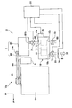
- FIG. 3 is a schematic view showing the vehicle antifogging device of FIG.
- FIG. 4 is a cross-sectional view showing a desiccant device for dehumidification according to an embodiment of the present invention.
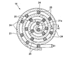
- FIG. 5 is a front view showing a first desiccant in the dehumidifying desiccant device of FIG. 6 is a cross-sectional view taken along the line VI-VI of FIG. 5 in the desiccant device for dehumidification of the present invention.
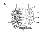
- FIG. 7 is a perspective view illustrating a state in which the first sheet of the first desiccant of FIG.
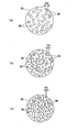
- FIG. 8A is a plan view showing the first desiccant first micro-humidifier
- FIG. 8B is a plan view showing the second desiccant second micro-dehumidifier
- FIG. 8C is the third desiccant. It is a top view which shows a 3rd micro dehumidifier.
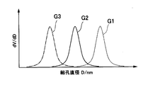
- FIG. 9 is a graph showing the pore diameters of the first to third microdehumidifiers of FIGS. 8 (a) to 8 (c) in a frequency distribution.
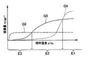
- FIG. 10 is a graph showing the relationship between the moisture adsorption amount of the first to third microdehumidifiers of FIGS. 8A to 8C and the relative humidity in the air.
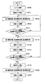
- FIG. 11 is a flowchart showing the operation of the vehicle antifogging device of the present invention.
- the arrow FR indicates the front of the vehicle
- the arrow LH indicates the left side of the vehicle.
- the vehicle Ve includes an air conditioner 1 and a vehicle antifogging device 2.
- the air conditioner 1 is a normal air conditioner used in a general vehicle Ve.
- the air conditioner 1 includes a compressor 3, a condenser 4, a receiver 5, an expansion valve (expansion valve) 6, and an evaporator 7.
- the vehicle antifogging device 2 includes a vacuum pump 8, a dehumidifying desiccant device 10, a first on-off valve 71, a second on-off valve 72, a third on-off valve 73, and a blower fan (second fan) 74 ( 3), a detection unit 76, and a control unit 77.
- the refrigerant is compressed as the compressor 3 rotates.
- the compressed refrigerant is sent to the condenser 4 in a high-temperature and high-pressure semi-liquid state.
- the refrigerant guided to the condenser 4 is cooled by the air blown by the condenser fan, and liquefaction proceeds.
- the liquefied refrigerant is sent to the receiver 5.
- the receiver 5 removes moisture and impurities from the refrigerant.
- the liquid refrigerant from which moisture and impurities have been removed is jetted toward the evaporator 7 by the expansion valve 6 and vaporized.
- the vaporized refrigerant removes the heat around the evaporator 7 and cools the evaporator 7. By passing air through the evaporator 7 with a blower fan, the air is cooled by the evaporator 7, and the cooled air is sent to the passenger compartment 78.
- the vacuum pump 8 of the vehicle antifogging device 2 has a pump body 81 and a driven pulley 82.
- the driven pulley 82 is connected to the drive shaft 81a of the pump body 81 through a connection / disconnection part.
- the driven pulley 82 is connected to a drive pulley 85 of an engine (drive source) 84 by an endless belt 86.
- the driven pulley 82 rotates through the endless belt 86.
- the drive shaft 81a of the pump main body 81 rotates and the vacuum pump 8 is driven.
- the vacuum pump 8 is driven, air and moisture inside the desiccant device 10 for dehumidification are sucked.
- the inside of the outer case of the dehumidifying desiccant device 10 can be kept in a reduced pressure state.
- the pump main body 81 stops by making the connection part of the pump main body 81 into a disconnected state.
- the suction port 81 b of the pump body 81 is communicated with the first exhaust port 10 a of the dehumidifying desiccant device 10 via the first intake flow path 88.
- the desiccant device 10 for dehumidification is arrange
- the instrument panel 92 is provided below the front window glass 93 (see FIG. 2).
- a first on-off valve 71 is provided in the middle of the first intake passage 88. The first on-off valve 71 is used in combination with a valve capable of leaking to the outside.
- the second exhaust port 10 c of the desiccant device 10 for dehumidification and the passenger compartment 78 are communicated with each other through a second exhaust passage 91.
- a second on-off valve 72 is provided in the middle of the second discharge channel 91.
- a blower fan 74 is provided on the outlet side of the second discharge channel 91.
- the intake port 10 b of the dehumidifying desiccant device 10 and the vehicle compartment 78 are communicated with each other through a third intake passage 89.
- a third on-off valve 73 is provided in the middle of the third intake passage 89.
- the blower fan 74 By providing the blower fan 74 on the outlet side of the second discharge channel 91, the air in the passenger compartment 78 can be guided to the inside of the desiccant device 10 for dehumidification through the third intake channel 89. Furthermore, the air sent into the desiccant device 10 for dehumidification is guided to the vehicle compartment 78 through the first to third desiccants 14, 16, 18 and the second discharge channel 91 of the desiccant device 10 for dehumidification. it can. That is, the blower fan 74 is a fan that sends the air of the desiccant device 10 for dehumidification to the vehicle compartment 78. Instead of the blower fan 74, a blower fan (first fan) that blows the air in the passenger compartment 78 to the third intake passage 89 can also be used.
- the detection unit 76 is provided in the desiccant device 10 for dehumidification.
- the detection unit 76 detects that a predetermined amount of moisture has been adsorbed by the desiccant device 10 for dehumidification.
- a humidity sensor or a weight sensor is used as the detection unit 76.
- the weight sensor is a sensor that detects by weight whether or not a predetermined amount of moisture is adsorbed on the dehumidifying desiccant device 10.
- Information from the detection unit 76 is sent to the control unit 77. Based on the detection information from the detection unit 76, the control unit 77 determines whether or not a predetermined amount of moisture is adsorbed on the dehumidifying desiccant device 10. When it is determined that a predetermined amount of moisture is not adsorbed to the desiccant device 10 for dehumidification, a signal is output to close the first on-off valve 71, open the second on-off valve 72, and open the third on-off valve 73. .
- the air in the passenger compartment 78 is guided to the desiccant device 10 for dehumidification through the third intake passage 89. .
- the moisture of the air guided to the desiccant device 10 for dehumidification is adsorbed by the desiccant device 10 for dehumidification, and the dry air in which the moisture is adsorbed is guided to the vehicle compartment 78.
- a signal for opening the first on-off valve 71, closing the second on-off valve 72, and closing the third on-off valve 73 is sent. Output.
- the moisture adsorbed on the dehumidifying desiccant device 10 is removed from the dehumidifying desiccant device 10.
- the desiccant device 10 for dehumidification will be described in detail with reference to FIGS.
- the first micro dehumidifier 24, the second micro dehumidifier 32, and the third micro dehumidifier 35 are omitted.
- the desiccant device 10 for dehumidification is provided in the flow path inside 13 of the flow path 12 through which air flows.
- the dehumidifying desiccant device 10 includes a first desiccant 14, a second desiccant 16, and a third desiccant 18 accommodated in the flow path interior 13 of the flow path 12.
- the side on which the first desiccant 14 is disposed is described as an upstream side
- the side on which the third desiccant 18 is disposed is described as a downstream side.
- the flow path 12 is formed in a circular cross section, for example.
- the flow path 12 can flow high relative humidity air as indicated by an arrow A from the upstream side of the first desiccant 14 toward the first desiccant 14.
- the dry air that has passed through the first desiccant 14, the second desiccant 16, and the third desiccant 18 can flow to the downstream side of the flow path 12 as indicated by arrow B.
- the first desiccant 14 includes a first sheet 21 wound in a spiral shape and a first minute dehumidifying agent in which a large number is included in the first sheet 21. 24 and a dehumidifying agent 25 that secures an interval S ⁇ b> 1 between the first sheets 21.
- the dehumidifying agent 25 serves both as a spacer that secures the interval S1 between the first sheets 21 and as an auxiliary dehumidifying agent.
- the auxiliary dehumidifying agent 25 is referred to as a first spacer dehumidifying agent 25.
- the first sheet 21 is, for example, a strip-shaped nonwoven fabric formed in the width dimension T1 (see FIG. 7) and including the first minute dehumidifying agent 24.
- the first minute dehumidifying agent 24 is a minute dehumidifying agent as compared with the first spacer dehumidifying agent 25.
- a plurality of first minute dehumidifying agents 24 are included in the interior 22 of the first sheet 21, and the first spacer dehumidifying agents 25 are arranged between the first sheets 21 at intervals.
- the first minute dehumidifying agent 24 and the first spacer dehumidifying agent 25 are formed of a material such as silica gel having excellent moisture (water vapor) adsorbability, for example.
- first fine dehumidifying agents 24 By arranging a plurality of first fine dehumidifying agents 24 in the interior 22 of the nonwoven fabric fibers of the first sheet 21, moisture arriving through the nonwoven fabric fibers is adsorbed by the first fine dehumidifying agents 24. Thereby, the water
- the first spacer dehumidifying agent 25 since the first spacer dehumidifying agent 25 is arranged, the first spacer 21 is secured in the space S1 between the first sheets 21 in a state where the first sheet 21 is spirally wound. . Since the first spacer dehumidifying agent 25 also serves as a spacer, it is not necessary to separately provide a spacer, and the configuration can be simplified.
- the space S1 can be reliably secured between the first sheets 21 with a simple configuration.
- the first spacer dehumidifier 25 is formed of a material such as silica gel having excellent moisture adsorbability, for example.
- the first minute dehumidifying agent 24 and the first spacer dehumidifying agent 25 are formed in a spherical shape with different outer diameters, and a large number of pores 26 (see FIG. 8A) are formed on the surface and inside. .
- a large number of pores 26 in the first minute dehumidifying agent 24 and the first spacer dehumidifying agent 25 the surface area of the first minute dehumidifying agent 24 and the first spacer dehumidifying agent 25 is ensured to be large, and the moisture adsorptivity. Can be increased.
- the first minute dehumidifying agent 24 and the first spacer dehumidifying agent 25 are not limited to a spherical shape, and may be modified or powdered.
- the pores of the first spacer dehumidifying agent 25 are preferably the same size as the pores 26 of the first minute dehumidifying agent 24, but even those having different pore size sizes are used to reinforce moisture adsorption. it can.
- a plurality of first minute dehumidifying agents 24 are carried inside the first sheet 21 (that is, non-woven fabric). Further, a plurality of first spacer dehumidifiers 25 are included between the first sheets 21.
- the some 1st micro dehumidifier 24 can be hold
- seat 21 in which the some 1st micro dehumidifier 24 was contained is wound by the spiral shape centering
- the first desiccant 14 can be easily formed with a simple configuration in which the first sheet 21 is wound in a spiral shape.
- the first desiccant 14 has a circular outer shape when the first sheet 21 is wound in a spiral shape. Therefore, the 1st desiccant 14 can be easily arrange
- the second desiccant 16 like the first desiccant 14, contains the second sheet 31, the second minute dehumidifier 32 (see FIG. 8B), and the second spacer dehumidifier 37. I have. Similar to the first sheet 21 (see also FIG. 5), the second sheet 31 is wound in a spiral shape. The second minute dehumidifying agent 32 is included in the second sheet 31 in the same manner as the first minute dehumidifying agent 24 (see FIG. 8A). Similar to the first spacer dehumidifying agent 25, the second spacer dehumidifying agent 37 is disposed between the second sheets 31.
- the pores of the second spacer dehumidifying agent 37 are preferably the same size as the pores 33 of the second minute dehumidifying agent 32, but even those having different pore size sizes are used to reinforce moisture adsorption. it can.
- the third desiccant 18 includes a third sheet 34, a third minute dehumidifying agent 35 (see FIG. 8C), and a third spacer dehumidifying agent 38. Similar to the first sheet 21 (see also FIG. 5), the third sheet 34 is wound in a spiral shape. The third minute dehumidifying agent 35 is included in the third sheet 34 in the same manner as the first minute dehumidifying agent 24 (see FIG. 8A). The third spacer dehumidifying agent 38 is disposed between the third sheets 34 in the same manner as the first spacer dehumidifying agent 25.
- the pores of the third spacer dehumidifier 38 are preferably the same size as the pores 36 of the third micro-dehumidifier 35, but even if the pore sizes are different, they are used to reinforce moisture adsorption. it can.
- the second desiccant 16 and the third desiccant 18 have the same configuration as the first desiccant 14 and will not be described in detail.
- seat 34 can also be made into an adhesive sheet.
- An adhesive sheet is a sheet in which an adhesive is applied to the surface of the sheet.
- a plurality of minute dehumidifying agents are attached to the adhesive of the adhesive sheet, and a plurality of spacer dehumidifying agents are attached.
- the first desiccant, the second desiccant, and the third desiccant are formed by winding the adhesive sheet in a spiral shape so as to have a dehumidifying performance and to secure an air flow path.
- The By using the first sheet 21, the second sheet 31, and the third sheet 34 as adhesive sheets, a plurality of minute dehumidifying agents and a plurality of spacer dehumidifying agents can be held in a stable state.
- the first minute dehumidifying agent 24 is, for example, a porous material formed in a spherical shape and having a large number of pores 26 formed on the surface and inside.
- the material of the first minute dehumidifying agent 24 include silica gel, zeolite, a polymeric moisture absorbent, and porous titania.
- the pore 26 is formed in the diameter D1.
- the diameter D1 of the pore 26 is referred to as “first pore diameter D1”.
- the second minute dehumidifying agent 32 is, for example, a porous material formed in a spherical shape and having a large number of pores 33 formed on the surface and inside.
- the second minute dehumidifying agent 32 is formed of the same material as the first minute dehumidifying agent 24.
- the pore 33 is formed in the diameter D2.
- the diameter D2 of the pore 33 is referred to as “second pore diameter D2”.
- the third minute dehumidifying agent 35 is, for example, a porous material formed in a spherical shape and having a large number of pores 36 formed on the surface and inside.
- the third minute dehumidifying agent 35 is formed of the same material as the first minute dehumidifying agent 24.
- the third minute dehumidifying agent 35 has pores 36 with a diameter D3.
- the diameter D3 of the pores 36 is referred to as “third pore diameter D3”.
- the first pore diameter D1 of the first minute dehumidifying agent 24 is formed larger than the second pore diameter D2 of the second minute dehumidifying agent 32.
- the second pore diameter D2 of the second minute dehumidifier 32 is formed larger than the third pore diameter D3 of the third minute dehumidifier 35.
- the first micro dehumidifier 24, the second micro dehumidifier 32, and the third micro dehumidifier 35 will be described.
- the vertical axis shows the frequency distribution
- the horizontal axis shows the pore diameters D1, D2, and D3 of the first to third fine dehumidifying agents 24, 32, and 35, respectively.
- a graph G1 indicated by a broken line shows a frequency distribution of the first minute dehumidifying agent 24 included in the first desiccant 14.
- a graph G ⁇ b> 2 indicated by a solid line shows a frequency distribution of the second minute dehumidifying agent 32 included in the second desiccant 16.
- a graph G ⁇ b> 3 indicated by a one-dot chain line indicates a frequency distribution of the third minute dehumidifying agent 35 included in the third desiccant 18.
- the fine desiccant 24 having the pores 26 having the first pore diameter D1 is included in the first desiccant 14.
- a second microdehumidifier 32 having a pore 33 having a second pore diameter D2 smaller than the first pore diameter D1 is included in the second desiccant 16.
- a third microdehumidifier 35 having a pore 36 with a third pore diameter D3 smaller than the second pore diameter D2 is included in the third desiccant 18.
- the number of desiccants is not limited to 2 or 3, and may be 4 (first to fourth desiccants) or more as necessary.
- the vertical axis represents the moisture adsorption amount of the dehumidifying agent and the horizontal axis represents the relative humidity.
- a graph G4 indicated by a broken line shows the relationship between the moisture adsorption amount of the first microdehumidifier 24 included in the first desiccant 14 and the relative humidity.
- a graph G5 indicated by a solid line shows the relationship between the amount of moisture adsorbed by the second minute dehumidifier 32 contained in the second desiccant 16 and the relative humidity.
- a graph G6 indicated by an alternate long and short dash line indicates the relationship between the amount of moisture adsorbed by the third microhumidifier 35 contained in the third desiccant 18 and the relative humidity.
- the first minute dehumidifying agent 24 has a large moisture adsorption amount in the region E1 where the relative humidity is high.
- the second minute dehumidifying agent 32 has a large moisture adsorption amount in the region E2 where the relative humidity is medium.
- the third minute dehumidifying agent 35 exhibits the adsorption performance even in the region E3 where the relative humidity is low, but the moisture adsorption amount is relatively small, and the moisture adsorption amount is also high in the region where the relative humidity is high. Does not grow.
- the region E1 where the relative humidity is high is a region where the relative humidity is higher than the relative humidity at the intersection of the graph G4 and the graph G5.
- the region E3 where the relative humidity is low is a region where the relative humidity is lower than the relative humidity at the intersection of the graph G5 and the graph G6, and the region E2 where the relative humidity is medium is a region between E1 and E3.
- the moisture in the air can be efficiently adsorbed by adsorbing the moisture in the air with the first minute dehumidifier 24.
- the moisture in the air can be efficiently adsorbed by adsorbing the moisture in the air with the second minute dehumidifier 32.
- the moisture in the air can be efficiently adsorbed by adsorbing moisture in the air with the third minute dehumidifying agent 35.
- the first desiccant 14 is disposed adjacent to the upstream side of the second desiccant 16 in the channel interior 13 of the channel 12.
- the second desiccant 16 is disposed adjacent to the upstream side of the third desiccant 18. Therefore, by flowing air having a high relative humidity from the upstream side of the flow path 12 as indicated by an arrow A, moisture in the air can be efficiently adsorbed by the first minute dehumidifying agent 24 of the first desiccant 14.
- the relative humidity of the air flowing out from the first desiccant 14 is suppressed to a medium level.
- Medium relative humidity air is passed from the first desiccant 14 to the second desiccant 16. Therefore, moisture in the air can be efficiently adsorbed by the second micro-humidifier 32 of the second desiccant 16.
- the relative humidity of the air flowing out from the second desiccant 16 is suppressed to a certain degree.
- Low relative humidity air is flowed from the second desiccant 16 to the third desiccant 18. Therefore, moisture in the air can be efficiently adsorbed by the third minute dehumidifying agent 35 of the third desiccant 18. Thereby, the air which flowed out from the 3rd desiccant 18 as shown by arrow B can be made into dry air.
- the second on-off valve 72 is closed, the third on-off valve 73 is closed, 1
- the on-off valve 71 is opened, and vacuuming is performed by the vacuum pump 8 (see FIG. 3).
- the inside of the dehumidifying desiccant apparatus 10 is depressurized, and all of the first desiccant 14, the second desiccant 16, and the third desiccant 18 are evacuated.
- the moisture adsorbed on the first micro dehumidifier 24, the second micro dehumidifier 32, and the third micro dehumidifier 35 can be removed, and the first micro dehumidifier 24,
- the 2nd micro dehumidifier 32 and the 3rd micro dehumidifier 35 can be recycled in a reuse state.
- the desiccant device 10 for dehumidification can be reduced in size compared with the desiccant device for dehumidification using the dehumidifier with the same porous pore diameter.
- the operation of the vehicle antifogging device 2 will be described with reference to the flowcharts of FIGS. While the vehicle Ve is stopped (that is, when the engine 84 is stopped), the first on-off valve 71 is closed, the second on-off valve 72 is closed, and the third on-off valve 73 is closed. The inside of the outer case is kept in a reduced pressure state. Further, the fine desiccants 24, 32, and 35 (see FIGS. 8A to 8C) of the first desiccant 14, the second desiccant 16, and the third desiccant 18 of the desiccant apparatus 10 for dehumidification are kept in a dry state. ing.
- step ST10 the engine 84 of the vehicle Ve is started.
- step ST11 the vacuum pump 8 is kept stopped.
- step ST12 the first on-off valve 71 is closed, the second on-off valve 72 is opened, and the third on-off valve 73 is set to open.
- the 2nd on-off valve 72 is opened. Thereby, the driving preparation of the vehicle Ve is completed.
- step ST13 The inside of the outer case of the desiccant device 10 for dehumidification is maintained at normal pressure (that is, atmospheric pressure).
- step ST13 the blower fan 74 is driven.
- the air in the compartment 78 is sent to the inside of the desiccant device 10 for dehumidification through the third intake passage 89.
- the air sent into the dehumidifying desiccant device 10 passes through the first to third desiccants 14, 16, and 18 of the dehumidifying desiccant device 10.
- Moisture in the air is adsorbed by the minute dehumidifiers 24, 32, and 35 (see FIG. 8) and the spacer dehumidifiers 25, 37, and 38 (see FIG. 4) of the first to third desiccants 14, 16, and 18, respectively. And moisture in the air is removed.
- the dry air from which moisture has been removed is sent from the desiccant device 10 for dehumidification to the passenger compartment 78 through the second discharge passage 91 as indicated by an arrow E.
- the desiccant device 10 for dehumidification is disposed below the instrument panel 92 (see FIG. 2). Accordingly, dry air from which moisture in the air has been removed can be sent below the front window glass 93 (see FIG. 2). Thereby, fogging of the front window glass 93 can be suppressed and fogging of the front window glass 93 can be removed.
- the windshield can be prevented from being fogged without operating the air conditioner 1 and using the dehumidifying effect due to condensation of water vapor due to supercooling.
- the air conditioner 1 by operating the air conditioner 1 to send the cooled air to the passenger compartment 78, the dry air guided to the passenger compartment 78 can be suitably cooled by the air conditioner 1. Therefore, by operating the air conditioner 1, further comfort of the passenger compartment 78 can be obtained.
- step ST14 it is determined whether or not a predetermined amount of moisture is adsorbed to the desiccant device 10 for dehumidification. If a predetermined amount of moisture is not adsorbed by the desiccant device 10 for dehumidification, the process returns to step 12. On the other hand, if a predetermined amount of moisture is adsorbed to the desiccant device 10 for dehumidification, the process proceeds to step 15. In step 15, the first on-off valve 71 is opened, the second on-off valve 72 is closed, and the third on-off valve 73 is closed. In step 16, the blower fan 74 is stopped. In step ST17, the vacuum pump 8 is driven.
- step ST18 it is determined whether or not a predetermined amount of moisture is adsorbed on the desiccant apparatus 10 for dehumidification. When a predetermined amount of moisture is adsorbed to the desiccant device 10 for dehumidification, the process returns to step 15.
- step 19 the vacuum pump 8 is stopped.
- step 20 the first on-off valve 71 is closed, the second on-off valve 72 is opened, and the third on-off valve 73 is set to open.
- the 2nd on-off valve 72 is opened.
- the inside of the outer case of the desiccant device 10 for dehumidification is maintained at normal pressure (that is, atmospheric pressure).
- step 21 the blower fan 74 is driven.
- the desiccant device 10 for dehumidification includes the first desiccant 14, the second desiccant 16, and the third desiccant 18 has been described.
- the present invention is not limited to this.
- only the first desiccant 14 and the second desiccant 16 can be provided.
- the desiccant device 10 for dehumidification can include three or more desiccants.
- the sheet 21, 31, 34 of the first to third desiccants 14, 16, 18 is spirally wound to form a circular shape in front view.
- the first to third desiccants can be formed in a cube shape (cube shape).
- a desiccant is formed by sandwiching a dehumidifying agent between flat meshes (mesh) and laminating the flat meshes with an interval in which air flows in the vertical direction.
- the desiccant apparatus 10 for dehumidification can be rotatably provided in the flow channel interior 13 of the flow channel 12.
- a dehumidifying agent can be movably accommodated in the case, and a flow path can be communicated with the case. By flowing air from the flow path into the case, the dehumidifying agent in the case is made to flow with air, and the moisture in the air can be adsorbed by the dehumidifying agent by making the air uniformly contact the dehumidifying agent in the case.
- the first to third desiccants 14, 16, and 18 are accommodated in the dehumidifying desiccant apparatus 10, and the first to third desiccants 14, 16, and 18 have different moisture adsorption properties.
- the desiccant device 10 for dehumidification can be configured to have a uniform moisture adsorptivity.
- Ve Vehicle 1 ... Air conditioner 2 ... Vehicle defogging device 8 ... Vacuum pump 10 ... Dehumidification desiccant device 10a ... First exhaust port 10b for dehumidification desiccant device 10c ... Air intake port 10c for dehumidification desiccant device Second exhaust port 71 ... first on-off valve 72 ... second on-off valve 73 ... third on-off valve 74 ... blower fan (second fan) 76 ... Detection unit 77 ... Control unit 78 ... Vehicle 81 88 ... 1st intake flow path 89 ... 3rd intake flow path 91 ... 2nd discharge flow path 92 ... Instrument panel
Landscapes
- Engineering & Computer Science (AREA)
- Mechanical Engineering (AREA)
- Air-Conditioning For Vehicles (AREA)
- Drying Of Gases (AREA)
Abstract
本発明は、電気消費量を抑えることができる車両用防曇装置および車両を提供する。車両用防曇装置(2)は、真空ポンプ(8)と、真空ポンプに連通された除湿用デシカント装置(10)とを備える。真空ポンプと除湿用デシカント装置の第1排気口との間に第1開閉弁(71)が設けられる。除湿用デシカント装置の第2排気口と車室(78)との間に第2開閉弁(72)が設けられる。除湿用デシカント装置の吸気口と車室との間に第3開閉弁(73)が設けられる。第1開閉弁を閉、第2開閉弁を開、第3開閉弁を開とし、除湿された乾燥空気を車室に戻す。一方、第1開閉弁を開、第2開閉弁を閉、第3開閉弁を閉とし、除湿用デシカント装置に吸着した水分を除湿用デシカント装置から除去する。
Description
本発明は、車両用防曇装置および車両に関する。
近年、電気自動車、ハイブリッド自動車等の導入が進めされている。これらの電気自動車は、冬季になると外気が車室内温度より低温になり乗員から排出される水蒸気で窓ガラスが曇りやすくなる(特許文献1)。
この傾向は、エンジンを備えた通常の車両にも同様に起こり得る。エンジンを備えた通常の車両の場合、空調装置で窓ガラスの曇を抑えることができる。しかし、空調装置で窓ガラスの曇を抑えるためには、電気消費量が増し、この観点から車両用防曇装置の実用化が望まれている。
この傾向は、エンジンを備えた通常の車両にも同様に起こり得る。エンジンを備えた通常の車両の場合、空調装置で窓ガラスの曇を抑えることができる。しかし、空調装置で窓ガラスの曇を抑えるためには、電気消費量が増し、この観点から車両用防曇装置の実用化が望まれている。
本発明は、電気消費量を抑えることができる車両用防曇装置および車両を提供する。
本発明は以下の構成を有する。
[1]真空ポンプと、前記真空ポンプおよび車室に連通され、空気の水分を吸着する除湿用デシカント装置と、を備えた、車両用防曇装置。[2]前記真空ポンプの吸込口および前記除湿用デシカント装置の第1排気口間に設けられた第1開閉弁と、前記除湿用デシカント装置の第2排気口および車室間に設けられた第2開閉弁と、前記除湿用デシカント装置の吸気口および前記車室間に設けられた第3開閉弁と、を備え、前記第1開閉弁を閉、前記第2開閉弁を開、前記第3開閉弁を開とすることにより前記車室の空気を前記除湿用デシカント装置に導き、前記除湿用デシカント装置で水分が吸着された空気を前記車室に導き、前記第1開閉弁を開、前記第2開閉弁を閉、前記第3開閉弁を閉とすることにより、前記除湿用デシカント装置に吸着した水分を前記除湿用デシカント装置から除去する、[1]に記載の車両用防曇装置。[3]前記除湿用デシカント装置に所定量の水分が吸着されたことを検知する検知部と、前記検知部からの検知情報に基づいて、前記除湿用デシカント装置に所定量の水分が吸着されていないと判断した場合に、前記第1開閉弁を閉、前記第2開閉弁を開、前記第3開閉弁を開とし、前記除湿用デシカント装置に所定量の水分が吸着されていると判断した場合に、前記第1開閉弁を開、前記第2開閉弁を閉、前記第3開閉弁を閉とする信号を出力する制御部と、を備える、[2]に記載の車両用防曇装置。[4]前記検知部は、湿度センサである、[3]に記載の車両用防曇装置。[5]前記検知部は、前記除湿用デシカント装置に水分が所定量吸着されているか否かを重量で検知する重量センサである、[3]に記載の車両用防曇装置。[6]前記真空ポンプは、車両の駆動源に連結されている、[1]~[5]のいずれか1項に記載の車両用防曇装置。[7]前記車室の空気を前記除湿用デシカント装置に送る第1ファンと、前記除湿用デシカント装置の空気を前記車室に送る第2ファンと、の一方を備えた、[1]~[6]のいずれか1項に記載の車両用防曇装置。[8]前記除湿用デシカント装置は、車両のインストルメントパネルの下方に配置されている、[1]~[7]のいずれか1項に記載の車両用防曇装置。[9][1]~[8]のいずれか1項に記載の車両用防曇装置と、前記車室に冷却された空気を送る空調装置と、を備える、車両。
[1]真空ポンプと、前記真空ポンプおよび車室に連通され、空気の水分を吸着する除湿用デシカント装置と、を備えた、車両用防曇装置。[2]前記真空ポンプの吸込口および前記除湿用デシカント装置の第1排気口間に設けられた第1開閉弁と、前記除湿用デシカント装置の第2排気口および車室間に設けられた第2開閉弁と、前記除湿用デシカント装置の吸気口および前記車室間に設けられた第3開閉弁と、を備え、前記第1開閉弁を閉、前記第2開閉弁を開、前記第3開閉弁を開とすることにより前記車室の空気を前記除湿用デシカント装置に導き、前記除湿用デシカント装置で水分が吸着された空気を前記車室に導き、前記第1開閉弁を開、前記第2開閉弁を閉、前記第3開閉弁を閉とすることにより、前記除湿用デシカント装置に吸着した水分を前記除湿用デシカント装置から除去する、[1]に記載の車両用防曇装置。[3]前記除湿用デシカント装置に所定量の水分が吸着されたことを検知する検知部と、前記検知部からの検知情報に基づいて、前記除湿用デシカント装置に所定量の水分が吸着されていないと判断した場合に、前記第1開閉弁を閉、前記第2開閉弁を開、前記第3開閉弁を開とし、前記除湿用デシカント装置に所定量の水分が吸着されていると判断した場合に、前記第1開閉弁を開、前記第2開閉弁を閉、前記第3開閉弁を閉とする信号を出力する制御部と、を備える、[2]に記載の車両用防曇装置。[4]前記検知部は、湿度センサである、[3]に記載の車両用防曇装置。[5]前記検知部は、前記除湿用デシカント装置に水分が所定量吸着されているか否かを重量で検知する重量センサである、[3]に記載の車両用防曇装置。[6]前記真空ポンプは、車両の駆動源に連結されている、[1]~[5]のいずれか1項に記載の車両用防曇装置。[7]前記車室の空気を前記除湿用デシカント装置に送る第1ファンと、前記除湿用デシカント装置の空気を前記車室に送る第2ファンと、の一方を備えた、[1]~[6]のいずれか1項に記載の車両用防曇装置。[8]前記除湿用デシカント装置は、車両のインストルメントパネルの下方に配置されている、[1]~[7]のいずれか1項に記載の車両用防曇装置。[9][1]~[8]のいずれか1項に記載の車両用防曇装置と、前記車室に冷却された空気を送る空調装置と、を備える、車両。
本発明の車両用防曇装置および車両によれば、真空ポンプと除湿用デシカント装置とを備える。よって、車室の空気を除湿用デシカント装置に導いて除湿し、除湿された乾燥空気を車室に戻すことにより、車両のフロント窓ガラスの曇を除湿用デシカント装置で防止できる。これにより、フロント窓ガラスの防曇のために必要な電気消費量を抑えることができる。
つぎに、本発明の実施形態を図面に基づいて説明する。図面において、矢印FRは車両の前方、矢印LHは車両の左側方を示す。
図1、図2に示すように、車両Veは、空調装置1と、車両用防曇装置2とを備えている。空調装置1は、一般の車両Veに使用されている通常の空調装置である。空調装置1は、コンプレッサ3と、コンデンサ4と、レシーバ5と、エキスパンジョンバルブ(膨張弁)6と、エバポレータ7とを備えている。
車両用防曇装置2は、真空ポンプ8と、除湿用デシカント装置10と、第1開閉弁71と、第2開閉弁72と、第3開閉弁73と、送風ファン(第2ファン)74(図3参照)と、検知部76と、制御部77とを備えている。
車両用防曇装置2は、真空ポンプ8と、除湿用デシカント装置10と、第1開閉弁71と、第2開閉弁72と、第3開閉弁73と、送風ファン(第2ファン)74(図3参照)と、検知部76と、制御部77とを備えている。
空調装置1は、コンプレッサ3が回転することにより冷媒が圧縮される。圧縮された冷媒が高温高圧の半液体の状態でコンデンサ4に送られる。コンデンサ4に導かれた冷媒はコンデンサファンで送風された空気で冷却されて液化が進む。液化が進んだ冷媒はレシーバ5に送られる。レシーバ5で冷媒から水分、不純物が取り除かれる。
水分、不純物が取り除かれた液状の冷媒はエキスパンジョンバルブ6でエバポレータ7に向けて噴射されて気化する。気化した冷媒でエバポレータ7の周囲の熱を奪い、エバポレータ7が冷却される。エバポレータ7にブロアファンで空気を通すことにより、エバポレータ7で空気を冷却し、冷却された空気を車室78に送る。
水分、不純物が取り除かれた液状の冷媒はエキスパンジョンバルブ6でエバポレータ7に向けて噴射されて気化する。気化した冷媒でエバポレータ7の周囲の熱を奪い、エバポレータ7が冷却される。エバポレータ7にブロアファンで空気を通すことにより、エバポレータ7で空気を冷却し、冷却された空気を車室78に送る。
図3に示すように、車両用防曇装置2の真空ポンプ8は、ポンプ本体81と、従動プーリ82とを有する。従動プーリ82は、ポンプ本体81の駆動軸81aに接断部を介して連結されている。従動プーリ82は、エンジン(駆動源)84の駆動プーリ85に無端状のベルト86で連結されている。
エンジン84が駆動して駆動プーリ85が回転することにより、従動プーリ82が無端状のベルト86を介して回転する。ポンプ本体81の接断部を接続状態にすることにより、ポンプ本体81の駆動軸81aが回転して真空ポンプ8が駆動する。真空ポンプ8が駆動することにより、除湿用デシカント装置10の内部の空気および水分を吸引する。
また、真空ポンプ8が駆動することにより、除湿用デシカント装置10の外装ケース内を減圧状態に保つことができる。
一方、ポンプ本体81の接断部を断絶状態にすることによりポンプ本体81が停止する。
また、真空ポンプ8が駆動することにより、除湿用デシカント装置10の外装ケース内を減圧状態に保つことができる。
一方、ポンプ本体81の接断部を断絶状態にすることによりポンプ本体81が停止する。
ポンプ本体81の吸込口81bが第1吸気流路88を介して除湿用デシカント装置10の第1排気口10aに連通されている。除湿用デシカント装置10は、車両Veのインストルメントパネル92(図2参照)の下方に配置されている。インストルメントパネル92は、フロント窓ガラス93(図2参照)の下方に設けられている。
第1吸気流路88の途中に第1開閉弁71が設けられている。第1開閉弁71は、外部へのリークが可能な弁を併用している。
第1吸気流路88の途中に第1開閉弁71が設けられている。第1開閉弁71は、外部へのリークが可能な弁を併用している。
除湿用デシカント装置10の第2排気口10cと車室78とが第2排出流路91で連通されている。第2排出流路91の途中に第2開閉弁72が設けられている。第2排出流路91の出口側に送風ファン74が設けられている。除湿用デシカント装置10の吸気口10bと車室78が第3吸気流路89で連通されている。第3吸気流路89の途中に第3開閉弁73が設けられている。
第2排出流路91の出口側に送風ファン74を設けることにより、車室78の空気を第3吸気流路89を経て除湿用デシカント装置10の内部に導くことができる。さらに、除湿用デシカント装置10の内部に送られた空気を、除湿用デシカント装置10の第1~第3のデシカント14,16,18および第2排出流路91を経て車室78へ導くことができる。
すなわち、送風ファン74は、除湿用デシカント装置10の空気を車室78に送るファンである。送風ファン74に代えて、車室78の空気を第3吸気流路89に送風する送風ファン(第1ファン)も使用できる。
すなわち、送風ファン74は、除湿用デシカント装置10の空気を車室78に送るファンである。送風ファン74に代えて、車室78の空気を第3吸気流路89に送風する送風ファン(第1ファン)も使用できる。
除湿用デシカント装置10に検知部76が設けられている。検知部76は、除湿用デシカント装置10に所定量の水分が吸着されたことを検知するものである。検知部76として、例えば、湿度センサ、重量センサが用いられる。重量センサは、除湿用デシカント装置10に水分が所定量吸着されているか否かを重量で検知するセンサである。
検知部76からの情報は制御部77に送られる。制御部77は、検知部76からの検知情報に基づいて、除湿用デシカント装置10に所定量の水分が吸着されているか否かを判断する。
除湿用デシカント装置10に所定量の水分が吸着されていないと判断した場合に、第1開閉弁71を閉、第2開閉弁72を開、第3開閉弁73を開とする信号を出力する。
第1開閉弁71を閉、第2開閉弁72を開、第3開閉弁73を開とすることにより車室78の空気を第3吸気流路89を経て除湿用デシカント装置10に案内される。
除湿用デシカント装置10に案内された空気の水分を除湿用デシカント装置10で吸着し、水分が吸着された乾燥空気を車室78に案内する。
除湿用デシカント装置10に所定量の水分が吸着されていないと判断した場合に、第1開閉弁71を閉、第2開閉弁72を開、第3開閉弁73を開とする信号を出力する。
第1開閉弁71を閉、第2開閉弁72を開、第3開閉弁73を開とすることにより車室78の空気を第3吸気流路89を経て除湿用デシカント装置10に案内される。
除湿用デシカント装置10に案内された空気の水分を除湿用デシカント装置10で吸着し、水分が吸着された乾燥空気を車室78に案内する。
一方、除湿用デシカント装置10に所定量の水分が吸着されていると判断した場合に、第1開閉弁71を開、第2開閉弁72を閉、第3開閉弁73を閉とする信号を出力する。
第2開閉弁72を閉、第3開閉弁73を閉、第1開閉弁71を開とすることにより、除湿用デシカント装置10に吸着した水分を除湿用デシカント装置10から除去する。
これにより、除湿用デシカント装置10の操作が容易になり、除湿用デシカント装置10の使い勝手を一層高めることができる。
第2開閉弁72を閉、第3開閉弁73を閉、第1開閉弁71を開とすることにより、除湿用デシカント装置10に吸着した水分を除湿用デシカント装置10から除去する。
これにより、除湿用デシカント装置10の操作が容易になり、除湿用デシカント装置10の使い勝手を一層高めることができる。
つぎに、除湿用デシカント装置10について図4~図10に基づいて詳しく説明する。
なお、図4においては、除湿用デシカント装置10の構成の理解を容易にするために、第1微小除湿剤24、第2微小除湿剤32および第3微小除湿剤35を省略して示す。
なお、図4においては、除湿用デシカント装置10の構成の理解を容易にするために、第1微小除湿剤24、第2微小除湿剤32および第3微小除湿剤35を省略して示す。
図4に示すように、除湿用デシカント装置10は、空気を流す流路12の流路内部13に設けられている。除湿用デシカント装置10は、流路12の流路内部13に収容された第1デシカント14、第2デシカント16、第3デシカント18を備えている。
以下、流路12において、第1デシカント14が配置されている側を上流側、第3デシカント18が配置されている側を下流側として説明する。
以下、流路12において、第1デシカント14が配置されている側を上流側、第3デシカント18が配置されている側を下流側として説明する。
流路12は、たとえば、断面円形に形成されている。流路12は、第1デシカント14の上流側から第1デシカント14に向けて高相対湿度の空気を矢印Aの如く流すことができる。第1デシカント14、第2デシカント16、および第3デシカント18を通過した乾燥空気を矢印Bの如く流路12の下流側に流すことができる。
図5、図6に示すように、第1デシカント14は、渦巻状に巻回(巻きめぐら)された第1シート21と、第1シート21に多量の個数が含まれた第1微小除湿剤24と、第1シート21間の間隔S1を確保する除湿剤25とを備えている。
第1シート21間の間隔S1を除湿剤25で確保することにより、間隔S1で空気の流路を確保できる。すなわち、除湿剤25は、第1シート21間の間隔S1を確保するスペーサとしての役割と、補助的な除湿剤としての役割を兼ねる。以下、補助的な除湿剤25を、第1スペーサ除湿剤25という。
第1シート21間の間隔S1を除湿剤25で確保することにより、間隔S1で空気の流路を確保できる。すなわち、除湿剤25は、第1シート21間の間隔S1を確保するスペーサとしての役割と、補助的な除湿剤としての役割を兼ねる。以下、補助的な除湿剤25を、第1スペーサ除湿剤25という。
第1シート21は、例えば、幅寸法T1(図7参照)に形成され、第1微小除湿剤24を含んだ帯状の不織布である。第1微小除湿剤24は、第1スペーサ除湿剤25と比較して微小な除湿剤である。第1シート21の内部22に複数の第1微小除湿剤24が含まれており、第1スペーサ除湿剤25が第1シート21の間に間隔をおいて配置されている。
第1微小除湿剤24と第1スペーサ除湿剤25とは、たとえば、水分(水蒸気)の吸着性に優れたシリカゲル等の素材で形成されている。第1シート21の不織布繊維の内部22に複数の第1微小除湿剤24が配置されることにより、不織布繊維の間を通って到着した水分は第1微小除湿剤24に吸着される。これにより、第1デシカント14の水分の吸着性を高めることができる。
第1微小除湿剤24と第1スペーサ除湿剤25とは、たとえば、水分(水蒸気)の吸着性に優れたシリカゲル等の素材で形成されている。第1シート21の不織布繊維の内部22に複数の第1微小除湿剤24が配置されることにより、不織布繊維の間を通って到着した水分は第1微小除湿剤24に吸着される。これにより、第1デシカント14の水分の吸着性を高めることができる。
また、第1スペーサ除湿剤25が配置されることにより、第1シート21が渦巻状に巻回された状態において、第1シート21間の間隔S1が第1スペーサ除湿剤25で確保されている。第1スペーサ除湿剤25がスペーサの役割も兼ねることにより、スペーサを個別に備える必要がなく、構成の簡素化が図れる。
このように、第1シート21の間に複数の第1スペーサ除湿剤25を配置することにより、第1シート21間に空間S1を簡単な構成で確実に確保できる。
また、第1スペーサ除湿剤25は、たとえば、水分の吸着性に優れたシリカゲル等の素材で形成されている。水分の吸着性に優れた素材を第1スペーサ除湿剤25に使用することにより、第1微小除湿剤24による空気中の水分の吸着性に加え、その性能を一層高めることができる。
また、第1スペーサ除湿剤25は、たとえば、水分の吸着性に優れたシリカゲル等の素材で形成されている。水分の吸着性に優れた素材を第1スペーサ除湿剤25に使用することにより、第1微小除湿剤24による空気中の水分の吸着性に加え、その性能を一層高めることができる。
第1微小除湿剤24および第1スペーサ除湿剤25は、実施形態では、外径が異なる球状に形成され、表面、内部に多数の細孔26(図8(a)参照)が形成されている。第1微小除湿剤24および第1スペーサ除湿剤25に多数の細孔26が形成されることにより、第1微小除湿剤24および第1スペーサ除湿剤25の表面積を大きく確保し、水分の吸着性を高めることができる。
第1微小除湿剤24および第1スペーサ除湿剤25は球状に限らず、異形、粉末も使用できる。
第1スペーサ除湿剤25の細孔は、第1微小除湿剤24の細孔26に対して、同一サイズであることが好ましいが、細孔径サイズが異なるものでも水分の吸着を補強するものとして使用できる。
第1微小除湿剤24および第1スペーサ除湿剤25は球状に限らず、異形、粉末も使用できる。
第1スペーサ除湿剤25の細孔は、第1微小除湿剤24の細孔26に対して、同一サイズであることが好ましいが、細孔径サイズが異なるものでも水分の吸着を補強するものとして使用できる。
図6、図7に示すように、第1シート21(すなわち、不織布)の内部には複数の第1微小除湿剤24が複数担持される。さらに、第1シート21の間に複数の第1スペーサ除湿剤25が含まれる。第1シート21を不織布で形成することにより、第1シート21の内部22に複数の第1微小除湿剤24を安定させた状態で保持できる。
複数の第1微小除湿剤24が含まれた第1シート21が一端部21aを中心にして渦巻き状に巻回される。第1シート21を渦巻き状に巻回するだけの簡単な構成で第1デシカント14を容易に形成できる。
また、第1デシカント14は、第1シート21を渦巻状に巻回することにより、外形が正面視円形状に形成される。よって、第1デシカント14を、断面円形の流路12に容易に配置できる。
複数の第1微小除湿剤24が含まれた第1シート21が一端部21aを中心にして渦巻き状に巻回される。第1シート21を渦巻き状に巻回するだけの簡単な構成で第1デシカント14を容易に形成できる。
また、第1デシカント14は、第1シート21を渦巻状に巻回することにより、外形が正面視円形状に形成される。よって、第1デシカント14を、断面円形の流路12に容易に配置できる。
図4に戻って、第2デシカント16は、第1デシカント14と同様に、第2シート31と、第2微小除湿剤32(図8(b)参照)と、第2スペーサ除湿剤37とを備えている。
第2シート31は、第1シート21(図5も参照)と同様に、渦巻状に巻回されている。第2微小除湿剤32は、第1微小除湿剤24(図8(a)参照)と同様に、第2シート31の内部に含まれている。第2スペーサ除湿剤37は、第1スペーサ除湿剤25と同様に、第2シート31間に配置されている。
第2スペーサ除湿剤37の細孔は、第2微小除湿剤32の細孔33に対して、同一サイズであることが好ましいが、細孔径サイズが異なるものでも水分の吸着を補強するものとして使用できる。
第2シート31は、第1シート21(図5も参照)と同様に、渦巻状に巻回されている。第2微小除湿剤32は、第1微小除湿剤24(図8(a)参照)と同様に、第2シート31の内部に含まれている。第2スペーサ除湿剤37は、第1スペーサ除湿剤25と同様に、第2シート31間に配置されている。
第2スペーサ除湿剤37の細孔は、第2微小除湿剤32の細孔33に対して、同一サイズであることが好ましいが、細孔径サイズが異なるものでも水分の吸着を補強するものとして使用できる。
第3デシカント18は、第1デシカント14と同様に、第3シート34と、第3微小除湿剤35(図8(c)参照)と、第3スペーサ除湿剤38とを備えている。
第3シート34は、第1シート21(図5も参照)と同様に、渦巻状に巻回されている。第3微小除湿剤35は、第1微小除湿剤24(図8(a)参照)と同様に、第3シート34の内部に含まれている。第3スペーサ除湿剤38は、第1スペーサ除湿剤25と同様に、第3シート34間に配置されている。
第3スペーサ除湿剤38の細孔は、第3微小除湿剤35の細孔36に対して、同一サイズであることが好ましいが、細孔径サイズが異なるものでも水分の吸着を補強するものとして使用できる。
第2デシカント16、第3デシカント18は、第1デシカント14と同様の構成であり、詳しい説明を省略する。
第3シート34は、第1シート21(図5も参照)と同様に、渦巻状に巻回されている。第3微小除湿剤35は、第1微小除湿剤24(図8(a)参照)と同様に、第3シート34の内部に含まれている。第3スペーサ除湿剤38は、第1スペーサ除湿剤25と同様に、第3シート34間に配置されている。
第3スペーサ除湿剤38の細孔は、第3微小除湿剤35の細孔36に対して、同一サイズであることが好ましいが、細孔径サイズが異なるものでも水分の吸着を補強するものとして使用できる。
第2デシカント16、第3デシカント18は、第1デシカント14と同様の構成であり、詳しい説明を省略する。
実施形態では、第1シート21、第2シート31、第3シート34を不織布で形成した例について説明するが、これに限らない。たとえば、第1シート21、第2シート31、第3シート34を粘着性シートとすることもできる。
粘着性シートとは、シートの表面に接着剤が塗布されたシートである。粘着性シートの接着剤に複数の微小除湿剤が付着され、かつ、複数のスペーサ除湿剤が付着される。この状態で、粘着性シートを渦巻状に巻回することにより、除湿性能を有し、空気の流路を確保することで圧力損失の少ない第1デシカント、第2デシカント、第3デシカントが形成される。
第1シート21、第2シート31、第3シート34を粘着性シートとすることにより、シートに複数の微小除湿剤、複数のスペーサ除湿剤を安定させた状態で保持できる。
粘着性シートとは、シートの表面に接着剤が塗布されたシートである。粘着性シートの接着剤に複数の微小除湿剤が付着され、かつ、複数のスペーサ除湿剤が付着される。この状態で、粘着性シートを渦巻状に巻回することにより、除湿性能を有し、空気の流路を確保することで圧力損失の少ない第1デシカント、第2デシカント、第3デシカントが形成される。
第1シート21、第2シート31、第3シート34を粘着性シートとすることにより、シートに複数の微小除湿剤、複数のスペーサ除湿剤を安定させた状態で保持できる。
図8(a)に示すように、第1微小除湿剤24は、一例として、球状に形成され、表面、内部に多数の細孔26が形成された多孔質の素材である。第1微小除湿剤24の素材として、シリカゲル、ゼオライト、高分子吸湿剤、多孔質チタニアなどが挙げられる。
第1微小除湿剤24は、細孔26が直径D1に形成されている。以下、細孔26の直径D1を「第1細孔直径D1」という。
第1微小除湿剤24は、細孔26が直径D1に形成されている。以下、細孔26の直径D1を「第1細孔直径D1」という。
図8(b)に示すように、第2微小除湿剤32は、一例として、球状に形成され、表面、内部に多数の細孔33が形成された多孔質の素材である。第2微小除湿剤32は、第1微小除湿剤24と同様の素材で形成されている。第2微小除湿剤32は、細孔33が直径D2に形成されている。以下、細孔33の直径D2を「第2細孔直径D2」という。
図8(c)に示すように、第3微小除湿剤35は、一例として、球状に形成され、表面、内部に多数の細孔36が形成された多孔質の素材である。第3微小除湿剤35は、第1微小除湿剤24と同様の素材で形成されている。第3微小除湿剤35は、細孔36が直径D3に形成されている。以下、細孔36の直径D3を「第3細孔直径D3」という。
図8(a)~8(c)に示すように、第1微小除湿剤24の第1細孔直径D1は、第2微小除湿剤32の第2細孔直径D2より大きく形成されている。第2微小除湿剤32の第2細孔直径D2は、第3微小除湿剤35の第3細孔直径D3より大きく形成されている。
図8(a)~8(c)、図9において、第1微小除湿剤24、第2微小除湿剤32、第3微小除湿剤35について説明する。図9に示すグラフは、縦軸に度数分布を示し、横軸に第1~第3の微小除湿剤24,32,35の各細孔直径D1,D2,D3を示す。破線で示すグラフG1は、第1デシカント14に含まれる第1微小除湿剤24の度数分布を示す。実線で示すグラフG2は、第2デシカント16に含まれる第2微小除湿剤32の度数分布を示す。一点鎖線で示すグラフG3は、第3デシカント18に含まれる第3微小除湿剤35の度数分布を示す。
第1細孔直径D1の細孔26を有する微小除湿剤24は、第1デシカント14に含まれている。第2細孔直径D2が第1細孔直径D1より小さい細孔33を有する第2微小除湿剤32は、第2デシカント16に含まれている。第3細孔直径D3が第2細孔直径D2より小さい細孔36を有する第3微小除湿剤35は、第3デシカント18に含まれている。なお、本発明では、デシカントの数は、2又は3に限られず、必要に応じて4(第1~第4デシカント)以上でもよい。
図8(a)~8(c)、図10において、第1微小除湿剤24、第2微小除湿剤32、第3微小除湿剤35における水分の吸着量について説明する。図10に示すグラフは、縦軸に除湿剤の水分吸着量を示し、横軸に相対湿度をとった、除湿剤の吸着水分量の相対湿度依存特性を示す。破線で示すグラフG4は、第1デシカント14に含まれる第1微小除湿剤24の水分の吸着量と相対湿度との関係を示す。実線で示すグラフG5は、第2デシカント16に含まれる第2微小除湿剤32の水分の吸着量と相対湿度との関係を示す。一点鎖線で示すグラフG6は、第3デシカント18に含まれる第3微小除湿剤35の水分の吸着量と相対湿度との関係を示す。
グラフG4で示すように、第1微小除湿剤24は相対湿度が高い領域E1において水分の吸着量が大きい。グラフG5で示すように、第2微小除湿剤32は相対湿度が中程度の領域E2において水分の吸着量が大きい。グラフG6で示すように、第3微小除湿剤35は、相対湿度が低い領域E3においても吸着性能を示すが、水分の吸着量は比較的少なく、相対湿度が高い領域においても水分の吸着量は大きくならない。ここで相対湿度が高い領域E1とは、グラフG4とグラフG5との交点における相対湿度よりも相対湿度が高い領域である。相対湿度が低い領域E3とは、グラフG5とグラフG6との交点における相対湿度よりも相対湿度が低い領域であり、相対湿度が中程度の領域E2はE1とE3との間の領域である。
よって、相対湿度が高い領域E1において、空気中の水分を第1微小除湿剤24で吸着することにより、空気中の水分を効率よく吸着できる。また、相対湿度が中程度の領域E2において、空気中の水分を第2微小除湿剤32で吸着することにより、空気中の水分を効率よく吸着できる。さらに、相対湿度が低い領域E3において、空気中の水分を第3微小除湿剤35で吸着することにより、空気中の水分を効率よく吸着できる。
図4に戻って、流路12の流路内部13において、第1デシカント14は第2デシカント16の上流側に隣接して配置されている。第2デシカント16は第3デシカント18の上流側に隣接して配置されている。
よって、流路12の上流側から相対湿度が高い空気を矢印Aの如く流すことにより、第1デシカント14の第1微小除湿剤24で空気中の水分を効率よく吸着できる。
よって、流路12の上流側から相対湿度が高い空気を矢印Aの如く流すことにより、第1デシカント14の第1微小除湿剤24で空気中の水分を効率よく吸着できる。
第1デシカント14の第1微小除湿剤24で空気中の水分が吸着されることにより、第1デシカント14から流出した空気は、相対湿度が中程度に抑えられている。中程度の相対湿度の空気を第1デシカント14から第2デシカント16に流す。よって、第2デシカント16の第2微小除湿剤32で空気中の水分を効率よく吸着できる。
第2デシカント16の第2微小除湿剤32で空気中の水分が吸着されることにより、第2デシカント16から流出した空気は、相対湿度がある程度低く抑えられている。低く抑えられた相対湿度の空気を第2デシカント16から第3デシカント18に流す。よって、第3デシカント18の第3微小除湿剤35で空気中の水分を効率よく吸着できる。
これにより、第3デシカント18から矢印Bの如く流出した空気を乾燥空気とすることができる。
これにより、第3デシカント18から矢印Bの如く流出した空気を乾燥空気とすることができる。
一方、第1微小除湿剤24、第2微小除湿剤32、第3微小除湿剤35に吸着した水分を除去する場合には、第2開閉弁72を閉、第3開閉弁73を閉、第1開閉弁71を開とし、真空ポンプ8(図3参照)で真空引きを行う。
この場合、除湿用デシカント装置10の内部が減圧されて、第1デシカント14、第2デシカント16、第3デシカント18の全てが真空引きされる。
これにより、第1微小除湿剤24、第2微小除湿剤32、第3微小除湿剤35(図8(a)~(c)参照)に吸着した水分を除去でき、第1微小除湿剤24、第2微小除湿剤32、第3微小除湿剤35を再使用状態に再生できる。
この場合、除湿用デシカント装置10の内部が減圧されて、第1デシカント14、第2デシカント16、第3デシカント18の全てが真空引きされる。
これにより、第1微小除湿剤24、第2微小除湿剤32、第3微小除湿剤35(図8(a)~(c)参照)に吸着した水分を除去でき、第1微小除湿剤24、第2微小除湿剤32、第3微小除湿剤35を再使用状態に再生できる。
このように、第1デシカント14、第2デシカント16、第3デシカント18を上流側から下流側へ向けて順に配置することにより、相対湿度が高い領域から相対湿度が低い領域までの全領域において空気中の水分を効率よく吸着できる。これにより、多孔質の細孔直径が同じ除湿剤を使用した除湿用デシカント装置と比べて、除湿用デシカント装置10を小型にできる。
つぎに、車両用防曇装置2の動作を図3、図11のフローチャートに基づいて説明する。
車両Veの停車中(すなわち、エンジン84を停止した状態)において、第1開閉弁71を閉、第2開閉弁72を閉、第3開閉弁73を閉にセットされ、除湿用デシカント装置10の外装ケース内が減圧状態に保たれている。また、除湿用デシカント装置10の第1デシカント14、第2デシカント16、第3デシカント18の各微小除湿剤24,32,35(図8(a)~(c)参照)が乾燥状態に保たれている。
車両Veの停車中(すなわち、エンジン84を停止した状態)において、第1開閉弁71を閉、第2開閉弁72を閉、第3開閉弁73を閉にセットされ、除湿用デシカント装置10の外装ケース内が減圧状態に保たれている。また、除湿用デシカント装置10の第1デシカント14、第2デシカント16、第3デシカント18の各微小除湿剤24,32,35(図8(a)~(c)参照)が乾燥状態に保たれている。
ステップST10において、車両Veのエンジン84を始動する。ステップST11において真空ポンプ8を停止状態に保つ。ステップST12において、第1開閉弁71を閉、第2開閉弁72を開、第3開閉弁73を開にセットする。ここで、第3開閉弁73をゆっくり開いた後に、第2開閉弁72を開く。これにより、車両Veの運転準備が完了する。
除湿用デシカント装置10の外装ケース内が常圧(すなわち、大気圧)に保たれる。ステップST13において送風ファン74を駆動する。これにより、車室78の空気が第3吸気流路89を経て除湿用デシカント装置10の内部に送られる。除湿用デシカント装置10の内部に送られた空気は除湿用デシカント装置10の第1~第3のデシカント14,16,18を通過する。空気中の水分が第1~第3のデシカント14,16,18の各微小除湿剤24,32,35(図8参照)と各スペーサ除湿剤25,37,38(図4参照)とに吸着され、空気中の水分が除去される。
水分が除去された乾燥空気が除湿用デシカント装置10から第2排出流路91を経て車室78へ矢印Eの如く送られる。除湿用デシカント装置10は、インストルメントパネル92(図2参照)の下方に配置されている。
よって、フロント窓ガラス93(図2参照)の下方に、空気中の水分が除去された乾燥空気を送ることができる。これにより、フロント窓ガラス93の曇を抑え、かつ、フロント窓ガラス93の曇を除去できる。
このように、除湿用デシカント装置10を使用することにより、空調装置1の運転をして、過冷却による水蒸気の凝縮による除湿効果を用いずともフロント窓ガラスの防曇が可能となり、防曇のために必要な電気消費量を抑えることができる。
ここで、空調装置1を操作して車室78に冷却された空気を送ることにより、車室78に導かれた乾燥空気を空調装置1で好適に冷却できる。よって、空調装置1を操作することにより、車室78の一層の快適性が得られる。
よって、フロント窓ガラス93(図2参照)の下方に、空気中の水分が除去された乾燥空気を送ることができる。これにより、フロント窓ガラス93の曇を抑え、かつ、フロント窓ガラス93の曇を除去できる。
このように、除湿用デシカント装置10を使用することにより、空調装置1の運転をして、過冷却による水蒸気の凝縮による除湿効果を用いずともフロント窓ガラスの防曇が可能となり、防曇のために必要な電気消費量を抑えることができる。
ここで、空調装置1を操作して車室78に冷却された空気を送ることにより、車室78に導かれた乾燥空気を空調装置1で好適に冷却できる。よって、空調装置1を操作することにより、車室78の一層の快適性が得られる。
ステップST14において、除湿用デシカント装置10に所定量の水分が吸着されているか否かを判断する。除湿用デシカント装置10に所定量の水分が吸着されていない場合、ステップ12に戻る。
一方、除湿用デシカント装置10に所定量の水分が吸着されている場合、ステップ15に進む。ステップ15において、第1開閉弁71を開、第2開閉弁72を閉、第3開閉弁73を閉にセットする。ステップ16において送風ファン74を停止する。ステップST17において真空ポンプ8を駆動する。
一方、除湿用デシカント装置10に所定量の水分が吸着されている場合、ステップ15に進む。ステップ15において、第1開閉弁71を開、第2開閉弁72を閉、第3開閉弁73を閉にセットする。ステップ16において送風ファン74を停止する。ステップST17において真空ポンプ8を駆動する。
真空ポンプ8を駆動することにより、除湿用デシカント装置10の外装ケース内が減圧状態に保たれ、除湿用デシカント装置10の内部の空気および水分が真空ポンプ8で第1吸気流路88から第1開閉弁71から外部に排出される。よって、第1~第3のデシカント14,16,18の各微小除湿剤24,32,35(図8(a)~8(c)参照)と各スペーサ除湿剤25,37,38(図4参照)とから水分が除去される。
ステップST18において、除湿用デシカント装置10に所定量の水分が吸着されているか否かを判断する。除湿用デシカント装置10に所定量の水分が吸着されている場合、ステップ15に戻る。
ステップST18において、除湿用デシカント装置10に所定量の水分が吸着されているか否かを判断する。除湿用デシカント装置10に所定量の水分が吸着されている場合、ステップ15に戻る。
一方、除湿用デシカント装置10に所定量の水分が吸着されていない場合、ステップ19に進む。ステップ19において真空ポンプ8を停止する。ステップ20において、第1開閉弁71を閉、第2開閉弁72を開、第3開閉弁73を開にセットする。ここで、第3開閉弁73をゆっくり開いた後に、第2開閉弁72を開く。除湿用デシカント装置10の外装ケース内が常圧(すなわち、大気圧)に保たれる。ステップ21において送風ファン74を駆動する。
なお、本発明の技術範囲は上述した実施形態に限定されるものではなく、本発明の趣旨を逸脱しない範囲において種々の変更を加えることができる。
前記実施形態では、除湿用デシカント装置10として、第1デシカント14、第2デシカント16、第3デシカント18を備えた例について説明したが、これに限定しない。その他の例として、第1デシカント14、第2デシカント16のみを備えることもできる。また、除湿用デシカント装置10として3個以上のデシカントを備えることもできる。
前記実施形態では、除湿用デシカント装置10として、第1デシカント14、第2デシカント16、第3デシカント18を備えた例について説明したが、これに限定しない。その他の例として、第1デシカント14、第2デシカント16のみを備えることもできる。また、除湿用デシカント装置10として3個以上のデシカントを備えることもできる。
また、前記実施形態では、第1~第3のデシカント14,16,18の各シート21,31,34を渦巻き状に巻回することにより正面視円形に形成した例について説明したが、これに限定しない。その他の例として、第1~第3のデシカントをキューブ状(立方体状)に形成することもできる。
この場合、例えば、平坦なメッシュ(網目)間に除湿剤を挟み、平坦なメッシュを上下方向に空気が流れる間隔を空けて積層することによりデシカントが形成される。
この場合、例えば、平坦なメッシュ(網目)間に除湿剤を挟み、平坦なメッシュを上下方向に空気が流れる間隔を空けて積層することによりデシカントが形成される。
さらに、前記実施形態では、除湿用デシカント装置10を流路12の流路内部13に固定させる例について説明したが、これに限定しない。その他の例として、除湿用デシカント装置10を流路12の流路内部13に回転可能に設けることもできる。
また、前記実施形態では、第1~第3のデシカント14,16,18の各シート21,31,34の内部に各微小除湿剤24,32,35を保持する例について説明したが、これに限定しない。その他の例として、ケース内に除湿剤を移動自在に収容し、ケースに流路を連通させるように構成することもできる。ケース内に流路から空気を流すことにより、ケース内の除湿剤を空気で流動させ、ケース内の除湿剤に均等に空気を接触させることにより、空気中の水分を除湿剤で吸着できる。
さらに、前記実施形態では、除湿用デシカント装置10に第1~第3のデシカント14,16,18を収容し、第1~第3のデシカント14,16,18の水分の吸着性を異なる構成としたが、これに限定しない。その他の例として、除湿用デシカント装置10に、水分の吸着性が均等の構成とすることもできる。
本発明を詳細にまた特定の実施態様を参照して説明したが、本発明の精神と範囲を逸脱することなく様々な変更や修正を加えることができることは、当業者にとって明らかである。
本出願は、2017年2月20日出願の日本特許出願2017-029021に基づくものであり、その内容はここに参照として取り込まれる。
本出願は、2017年2月20日出願の日本特許出願2017-029021に基づくものであり、その内容はここに参照として取り込まれる。
Ve…車両
1……空調装置
2……車両用防曇装置
8……真空ポンプ
10…除湿用デシカント装置
10a…除湿用デシカント装置の第1排気口
10b…除湿用デシカント装置の吸気口
10c…除湿用デシカント装置の第2排気口
71…第1開閉弁
72…第2開閉弁
73…第3開閉弁
74…送風ファン(第2ファン)
76…検知部
77…制御部
78…車室
81…ポンプ本体
81b…ポンプ本体の吸込口
84…エンジン(駆動源)
88…第1吸気流路
89…第3吸気流路
91…第2排出流路
92…インストルメントパネル
1……空調装置
2……車両用防曇装置
8……真空ポンプ
10…除湿用デシカント装置
10a…除湿用デシカント装置の第1排気口
10b…除湿用デシカント装置の吸気口
10c…除湿用デシカント装置の第2排気口
71…第1開閉弁
72…第2開閉弁
73…第3開閉弁
74…送風ファン(第2ファン)
76…検知部
77…制御部
78…車室
81…ポンプ本体
81b…ポンプ本体の吸込口
84…エンジン(駆動源)
88…第1吸気流路
89…第3吸気流路
91…第2排出流路
92…インストルメントパネル
Claims (9)
- 真空ポンプと、
前記真空ポンプおよび車室に連通され、空気の水分を吸着する除湿用デシカント装置と、
を備えた、車両用防曇装置。 - 前記真空ポンプの吸込口および前記除湿用デシカント装置の第1排気口間に設けられた第1開閉弁と、
前記除湿用デシカント装置の第2排気口および車室間に設けられた第2開閉弁と、
前記除湿用デシカント装置の吸気口および前記車室間に設けられた第3開閉弁と、を備え、
前記第1開閉弁を閉、前記第2開閉弁を開、前記第3開閉弁を開とすることにより前記車室の空気を前記除湿用デシカント装置に導き、前記除湿用デシカント装置で水分が吸着された空気を前記車室に導き、
前記第1開閉弁を開、前記第2開閉弁を閉、前記第3開閉弁を閉とすることにより、前記除湿用デシカント装置に吸着した水分を前記除湿用デシカント装置から除去する、
請求項1に記載の車両用防曇装置。 - 前記除湿用デシカント装置に所定量の水分が吸着されたことを検知する検知部と、
前記検知部からの検知情報に基づいて、前記除湿用デシカント装置に所定量の水分が吸着されていないと判断した場合に、前記第1開閉弁を閉、前記第2開閉弁を開、前記第3開閉弁を開とし、前記除湿用デシカント装置に所定量の水分が吸着されていると判断した場合に、前記第1開閉弁を開、前記第2開閉弁を閉、前記第3開閉弁を閉とする信号を出力する制御部と、
を備える、請求項2に記載の車両用防曇装置。 - 前記検知部は、湿度センサである、
請求項3に記載の車両用防曇装置。 - 前記検知部は、前記除湿用デシカント装置に水分が所定量吸着されているか否かを重量で検知する重量センサである、
請求項3に記載の車両用防曇装置。 - 前記真空ポンプは、車両の駆動源に連結されている、
請求項1~5のいずれか1項に記載の車両用防曇装置。 - 前記車室の空気を前記除湿用デシカント装置に送る第1ファンと、
前記除湿用デシカント装置の空気を前記車室に送る第2ファンと、の一方を備えた、
請求項1~6のいずれか1項に記載の車両用防曇装置。 - 前記除湿用デシカント装置は、車両のインストルメントパネルの下方に配置されている、
請求項1~7のいずれか1項に記載の車両用防曇装置。 - 請求項1~8のいずれか1項に記載の車両用防曇装置と、
前記車室に冷却された空気を送る空調装置と、
を備える車両。
Applications Claiming Priority (2)
| Application Number | Priority Date | Filing Date | Title |
|---|---|---|---|
| JP2017029021A JP2020062897A (ja) | 2017-02-20 | 2017-02-20 | 車両用防曇装置および車両 |
| JP2017-029021 | 2017-02-20 |
Publications (1)
| Publication Number | Publication Date |
|---|---|
| WO2018151237A1 true WO2018151237A1 (ja) | 2018-08-23 |
Family
ID=63169573
Family Applications (1)
| Application Number | Title | Priority Date | Filing Date |
|---|---|---|---|
| PCT/JP2018/005350 Ceased WO2018151237A1 (ja) | 2017-02-20 | 2018-02-15 | 車両用防曇装置および車両 |
Country Status (2)
| Country | Link |
|---|---|
| JP (1) | JP2020062897A (ja) |
| WO (1) | WO2018151237A1 (ja) |
Citations (6)
| Publication number | Priority date | Publication date | Assignee | Title |
|---|---|---|---|---|
| JP2003211955A (ja) * | 2002-01-16 | 2003-07-30 | Oh-Young Kim | 酸素供給機能を有する車両用空気浄化装置 |
| JP2006064325A (ja) * | 2004-08-30 | 2006-03-09 | National Institute Of Advanced Industrial & Technology | デシカントネットワークシステム |
| JP2006306293A (ja) * | 2005-04-28 | 2006-11-09 | Honda Motor Co Ltd | 車両用空調装置 |
| JP2007083791A (ja) * | 2005-09-20 | 2007-04-05 | Toyota Motor Corp | 空気調和装置 |
| JP2009090979A (ja) * | 2008-11-25 | 2009-04-30 | National Institute Of Advanced Industrial & Technology | 小型デシカント空調装置 |
| JP2012061438A (ja) * | 2010-09-17 | 2012-03-29 | Gunma Prefecture | 高表面積型吸着剤による連続除湿装置 |
-
2017
- 2017-02-20 JP JP2017029021A patent/JP2020062897A/ja active Pending
-
2018
- 2018-02-15 WO PCT/JP2018/005350 patent/WO2018151237A1/ja not_active Ceased
Patent Citations (6)
| Publication number | Priority date | Publication date | Assignee | Title |
|---|---|---|---|---|
| JP2003211955A (ja) * | 2002-01-16 | 2003-07-30 | Oh-Young Kim | 酸素供給機能を有する車両用空気浄化装置 |
| JP2006064325A (ja) * | 2004-08-30 | 2006-03-09 | National Institute Of Advanced Industrial & Technology | デシカントネットワークシステム |
| JP2006306293A (ja) * | 2005-04-28 | 2006-11-09 | Honda Motor Co Ltd | 車両用空調装置 |
| JP2007083791A (ja) * | 2005-09-20 | 2007-04-05 | Toyota Motor Corp | 空気調和装置 |
| JP2009090979A (ja) * | 2008-11-25 | 2009-04-30 | National Institute Of Advanced Industrial & Technology | 小型デシカント空調装置 |
| JP2012061438A (ja) * | 2010-09-17 | 2012-03-29 | Gunma Prefecture | 高表面積型吸着剤による連続除湿装置 |
Also Published As
| Publication number | Publication date |
|---|---|
| JP2020062897A (ja) | 2020-04-23 |
Similar Documents
| Publication | Publication Date | Title |
|---|---|---|
| JP6513170B2 (ja) | 乗物用除湿装置 | |
| US9463683B2 (en) | Anti-fog and HVAC system for electric vehicles | |
| WO2018221740A1 (ja) | 換気システム | |
| CN103269886A (zh) | 用于机动车的空调装置和用于调节机动车乘客室中的气候的方法 | |
| JP4844514B2 (ja) | 調湿装置 | |
| JPH0867136A (ja) | 車両用空調装置 | |
| JP6415277B2 (ja) | 車両用の空調装置 | |
| JP5828140B2 (ja) | 車両用空調装置 | |
| JP5741895B2 (ja) | 電気自動車用防曇・空調システムの受電装置 | |
| JPH06257805A (ja) | 加湿機能付空気調和機 | |
| JP2006306293A (ja) | 車両用空調装置 | |
| JP2020062897A (ja) | 車両用防曇装置および車両 | |
| JP2012102887A (ja) | 空調システム | |
| JPWO2018151236A1 (ja) | 除湿用デシカント装置 | |
| CN110603161A (zh) | 用于hvac系统的多孔空气入口管道 | |
| WO2017221767A1 (ja) | 車両用空調装置 | |
| CN113969605B (zh) | 一种能够保持优质水质的空气制水系统 | |
| JP2013035484A (ja) | 車両用空調装置 | |
| JP6746434B2 (ja) | 空気調和装置 | |
| JP2008201199A (ja) | 車両用空調装置 | |
| JP7360071B2 (ja) | 空気調節装置、冷凍装置、および輸送用コンテナ | |
| JP2011173492A (ja) | 車両用空調装置 | |
| JP2002166123A (ja) | 除湿装置 | |
| WO2019177121A1 (ja) | 車両用の空調装置 | |
| CN109405092A (zh) | 空气处理机组 |
Legal Events
| Date | Code | Title | Description |
|---|---|---|---|
| 121 | Ep: the epo has been informed by wipo that ep was designated in this application |
Ref document number: 18754608 Country of ref document: EP Kind code of ref document: A1 |
|
| NENP | Non-entry into the national phase |
Ref country code: DE |
|
| 122 | Ep: pct application non-entry in european phase |
Ref document number: 18754608 Country of ref document: EP Kind code of ref document: A1 |
|
| NENP | Non-entry into the national phase |
Ref country code: JP |