WO2018151074A1 - 3次元プリンティング装置 - Google Patents
3次元プリンティング装置 Download PDFInfo
- Publication number
- WO2018151074A1 WO2018151074A1 PCT/JP2018/004817 JP2018004817W WO2018151074A1 WO 2018151074 A1 WO2018151074 A1 WO 2018151074A1 JP 2018004817 W JP2018004817 W JP 2018004817W WO 2018151074 A1 WO2018151074 A1 WO 2018151074A1
- Authority
- WO
- WIPO (PCT)
- Prior art keywords
- fiber bundle
- printing apparatus
- dimensional printing
- filament
- twisting
- Prior art date
Links
Images


Classifications
-
- B—PERFORMING OPERATIONS; TRANSPORTING
- B29—WORKING OF PLASTICS; WORKING OF SUBSTANCES IN A PLASTIC STATE IN GENERAL
- B29C—SHAPING OR JOINING OF PLASTICS; SHAPING OF MATERIAL IN A PLASTIC STATE, NOT OTHERWISE PROVIDED FOR; AFTER-TREATMENT OF THE SHAPED PRODUCTS, e.g. REPAIRING
- B29C64/00—Additive manufacturing, i.e. manufacturing of three-dimensional [3D] objects by additive deposition, additive agglomeration or additive layering, e.g. by 3D printing, stereolithography or selective laser sintering
- B29C64/30—Auxiliary operations or equipment
- B29C64/307—Handling of material to be used in additive manufacturing
- B29C64/321—Feeding
- B29C64/336—Feeding of two or more materials
-
- B—PERFORMING OPERATIONS; TRANSPORTING
- B29—WORKING OF PLASTICS; WORKING OF SUBSTANCES IN A PLASTIC STATE IN GENERAL
- B29C—SHAPING OR JOINING OF PLASTICS; SHAPING OF MATERIAL IN A PLASTIC STATE, NOT OTHERWISE PROVIDED FOR; AFTER-TREATMENT OF THE SHAPED PRODUCTS, e.g. REPAIRING
- B29C64/00—Additive manufacturing, i.e. manufacturing of three-dimensional [3D] objects by additive deposition, additive agglomeration or additive layering, e.g. by 3D printing, stereolithography or selective laser sintering
- B29C64/10—Processes of additive manufacturing
- B29C64/106—Processes of additive manufacturing using only liquids or viscous materials, e.g. depositing a continuous bead of viscous material
- B29C64/118—Processes of additive manufacturing using only liquids or viscous materials, e.g. depositing a continuous bead of viscous material using filamentary material being melted, e.g. fused deposition modelling [FDM]
-
- B—PERFORMING OPERATIONS; TRANSPORTING
- B29—WORKING OF PLASTICS; WORKING OF SUBSTANCES IN A PLASTIC STATE IN GENERAL
- B29C—SHAPING OR JOINING OF PLASTICS; SHAPING OF MATERIAL IN A PLASTIC STATE, NOT OTHERWISE PROVIDED FOR; AFTER-TREATMENT OF THE SHAPED PRODUCTS, e.g. REPAIRING
- B29C64/00—Additive manufacturing, i.e. manufacturing of three-dimensional [3D] objects by additive deposition, additive agglomeration or additive layering, e.g. by 3D printing, stereolithography or selective laser sintering
- B29C64/20—Apparatus for additive manufacturing; Details thereof or accessories therefor
- B29C64/205—Means for applying layers
- B29C64/209—Heads; Nozzles
-
- B—PERFORMING OPERATIONS; TRANSPORTING
- B29—WORKING OF PLASTICS; WORKING OF SUBSTANCES IN A PLASTIC STATE IN GENERAL
- B29C—SHAPING OR JOINING OF PLASTICS; SHAPING OF MATERIAL IN A PLASTIC STATE, NOT OTHERWISE PROVIDED FOR; AFTER-TREATMENT OF THE SHAPED PRODUCTS, e.g. REPAIRING
- B29C64/00—Additive manufacturing, i.e. manufacturing of three-dimensional [3D] objects by additive deposition, additive agglomeration or additive layering, e.g. by 3D printing, stereolithography or selective laser sintering
- B29C64/20—Apparatus for additive manufacturing; Details thereof or accessories therefor
- B29C64/227—Driving means
- B29C64/241—Driving means for rotary motion
-
- B—PERFORMING OPERATIONS; TRANSPORTING
- B33—ADDITIVE MANUFACTURING TECHNOLOGY
- B33Y—ADDITIVE MANUFACTURING, i.e. MANUFACTURING OF THREE-DIMENSIONAL [3-D] OBJECTS BY ADDITIVE DEPOSITION, ADDITIVE AGGLOMERATION OR ADDITIVE LAYERING, e.g. BY 3-D PRINTING, STEREOLITHOGRAPHY OR SELECTIVE LASER SINTERING
- B33Y30/00—Apparatus for additive manufacturing; Details thereof or accessories therefor
-
- B—PERFORMING OPERATIONS; TRANSPORTING
- B33—ADDITIVE MANUFACTURING TECHNOLOGY
- B33Y—ADDITIVE MANUFACTURING, i.e. MANUFACTURING OF THREE-DIMENSIONAL [3-D] OBJECTS BY ADDITIVE DEPOSITION, ADDITIVE AGGLOMERATION OR ADDITIVE LAYERING, e.g. BY 3-D PRINTING, STEREOLITHOGRAPHY OR SELECTIVE LASER SINTERING
- B33Y70/00—Materials specially adapted for additive manufacturing
- B33Y70/10—Composites of different types of material, e.g. mixtures of ceramics and polymers or mixtures of metals and biomaterials
-
- D—TEXTILES; PAPER
- D02—YARNS; MECHANICAL FINISHING OF YARNS OR ROPES; WARPING OR BEAMING
- D02G—CRIMPING OR CURLING FIBRES, FILAMENTS, THREADS, OR YARNS; YARNS OR THREADS
- D02G3/00—Yarns or threads, e.g. fancy yarns; Processes or apparatus for the production thereof, not otherwise provided for
- D02G3/44—Yarns or threads characterised by the purpose for which they are designed
-
- B—PERFORMING OPERATIONS; TRANSPORTING
- B29—WORKING OF PLASTICS; WORKING OF SUBSTANCES IN A PLASTIC STATE IN GENERAL
- B29B—PREPARATION OR PRETREATMENT OF THE MATERIAL TO BE SHAPED; MAKING GRANULES OR PREFORMS; RECOVERY OF PLASTICS OR OTHER CONSTITUENTS OF WASTE MATERIAL CONTAINING PLASTICS
- B29B15/00—Pretreatment of the material to be shaped, not covered by groups B29B7/00 - B29B13/00
- B29B15/08—Pretreatment of the material to be shaped, not covered by groups B29B7/00 - B29B13/00 of reinforcements or fillers
- B29B15/10—Coating or impregnating independently of the moulding or shaping step
- B29B15/12—Coating or impregnating independently of the moulding or shaping step of reinforcements of indefinite length
- B29B15/122—Coating or impregnating independently of the moulding or shaping step of reinforcements of indefinite length with a matrix in liquid form, e.g. as melt, solution or latex
Definitions
- the present invention relates to a three-dimensional printing apparatus.
- This application claims priority based on Japanese Patent Application No. 2017-025745 filed in Japan on February 15, 2017, the contents of which are incorporated herein by reference.
- Patent Document 1 describes a 3D printer (three-dimensional printing apparatus) that melts a resin filament by heat melting and forms a three-dimensional structure by stacking the melted resin filaments.
- a 3D printer three-dimensional printing apparatus
- it is considered to increase the strength of a three-dimensional structure to be formed by using a filament in which a resin such as carbon fiber or glass fiber is impregnated.
- continuous filaments may be discharged so as to bend on a platform or the like.
- the filaments are arranged so as to be bent, the filaments are gradually twisted, and the fibers inside the filaments are also twisted.
- the fibers inside the filaments are twisted in this way, the filaments are unintentionally deformed due to the restoring force of the fibers, and there is a possibility that a three-dimensional structure having a shape as designed cannot be produced.
- the present invention has been made in view of the above-described problems.
- a three-dimensional printing apparatus using a filament in which a fiber is impregnated with a resin the deformation of the filament due to twisting of the fiber is suppressed, and a three-dimensional structure as designed is obtained.
- the purpose is to enable production.
- a three-dimensional printing apparatus capable of continuously discharging linear filaments in which a fiber bundle is impregnated with a resin.
- a twisting means capable of changing the twisting amount or the twisting amount of the fiber bundle is provided.
- impregnation means for impregnating the resin on the fiber side
- extraction means for pulling out the filament from the impregnation means
- pressing means for pressing the filament drawn by the extraction means against an object to be discharged
- the twisting means is a fiber bundle twisting mechanism that twists the fiber bundle before being supplied to the impregnation means.
- the fiber bundle twisting mechanism twists the fiber bundle by rotating a fiber bundle bobbin around which the fiber bundle supplied to the impregnation means is wound.
- the twisting means is a filament twisting mechanism that twists the entire filament discharged from the impregnation means.
- the pressing means is a roller with a built-in heater.
- the twisting means is adjusted based on the design shape of the three-dimensional structure to be created, so that the twist amount is increased for a portion having a large curvature among the design shapes, It adjusts so that the said twist amount may become small with respect to a site
- the twisting means adjusts the twist amount to be larger as the number of fibers in the fiber bundle is larger when the curved portion is formed.
- the three-dimensional printing apparatus includes a twist adjusting unit capable of adjusting the twist amount of the fiber bundle. Therefore, by twisting the fiber bundle when molding the curved portion, the difference in required length between the fiber arranged inside the curved surface and the fiber arranged outside can be eliminated, and the filament The twist of the fiber which arises by making it curve can be eliminated. Therefore, according to the present invention, in a three-dimensional printing apparatus using a filament in which a fiber is impregnated with a resin, deformation of the filament due to twisting of the fiber can be suppressed, and a three-dimensional structure as designed can be made. In addition, when a three-dimensional structure is created without driving the twist adjustment unit using a filament, the twist gradually accumulated in the filament inside the three-dimensional printing apparatus is twisted by the twist adjustment unit, Can be resolved.
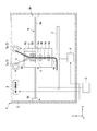
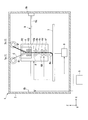
- FIG. 1 is an overall configuration diagram of a three-dimensional printing apparatus according to a first embodiment of the present invention. It is a schematic diagram which shows the shape of the filament formed in this invention. It is a whole block diagram of the three-dimensional printing apparatus which concerns on 2nd Embodiment of this invention. It is a whole block diagram of the three-dimensional printing apparatus which concerns on 3rd Embodiment of this invention. It is a graph which shows the comparison with the setting dimension at the time of twist generate
- the three-dimensional printing apparatus is configured such that a linear (thread-like) filament F including a resin (thermoplastic resin P) and a reinforcing fiber bundle C is continuously arranged on a plate-like platform. It is an apparatus to form. Specifically, for example, an apparatus (three-dimensional printing apparatus) that forms a three-dimensional structure by laminating filaments F on a platform in a softened state and then solidifying them. In addition to the platform, the object to be ejected includes a laminated filament F (structure).
- the filament F that is a raw material of the structure is impregnated with a reinforcing fiber bundle C such as carbon fiber or glass fiber in a thermoplastic resin P such as PLA resin (polylactic acid), ABS resin, or nylon resin. It is formed in a linear shape.
- a reinforcing fiber bundle C such as carbon fiber or glass fiber
- a thermoplastic resin P such as PLA resin (polylactic acid), ABS resin, or nylon resin. It is formed in a linear shape.
- a three-dimensional printing apparatus 1 includes a casing 2, a platform 3 disposed in the casing 2, a printer head 4 that supplies a filament F to the platform 3, a control device 5, and a twist adjusting unit. 6 (fiber bundle twisting mechanism), a bobbin 7, a platform driving device 8, and a header driving device 9.
- an arrow Z indicates a vertical direction (up and down direction)
- an arrow X indicates a horizontal direction
- an arrow Y indicates a horizontal direction that is orthogonal to the Z direction and the X direction.
- the casing 2 is a box-shaped housing having at least a front surface opened.
- the platform 3 is a rectangular plate parallel to the bottom surface 2 a of the casing 2.
- the platform 3 is disposed below the printer head 4 and in the vicinity of the bottom of the casing 2.
- the platform 3 is driven by the platform driving device 8 so as to be vertically movable in the vertical direction Z.
- the platform 3 is provided with a platform heating device (not shown) for heating the arranged filament F. In other words, the platform 3 has a function of heating the filament F disposed on the platform 3.
- the printer head 4 includes a heater 4a, an upper filament drawing device 4b (drawing means), a cutting device 4c, a lower filament drawing device 4d (drawing means), and a pressing roller 4e (pressing means). .
- the printer head 4 is connected to the fiber passage R1 through which the reinforcing fiber bundle C passes, the resin passage R2 through which the thermoplastic resin P passes, the fiber passage R1 and the resin passage R2, and is heated to cause the thermoplastic resin P to be heated. Is formed with an impregnation passage R3 in which the reinforcing fiber bundle C is impregnated.
- the heater 4a is provided on the side of the impregnation passage R3 and is melted by heating the thermoplastic resin P in the impregnation passage R3.
- the heater 4a and the impregnation passage R3 constitute the impregnation means in the present invention.
- the upper filament drawing device 4b is composed of two rollers, sandwiches the filament F impregnated with the thermoplastic resin P, and feeds it downward in the Z direction.
- the cutting device 4c is a device that is provided below the upper filament drawing device 4b and cuts the drawn filament F at an arbitrary position.
- the lower filament drawing device 4d is provided below the cutting device 4c, is configured by two rollers, and is a device that sends out the filament F toward the platform 3.
- the pressing roller 4e is a roller that has a built-in heater and presses the discharged filament F toward the platform 3 while heating it.
- the control device 5 is a computer that controls the printer head 4 and the platform 3. Specifically, the control device 5 is a device having a control program for controlling the printer head 4 and the like, a storage device for storing 3D data of structures, and a processor for executing the control program.
- the twist adjusting unit 6 is a device that forms a twist on the reinforcing fiber bundle C in a fiber bobbin 7a to be described later in the bobbin 7.
- the twist adjusting unit 6 causes the reinforcing fiber bundle C to form a twist by rotating the fiber bobbin 7a around the rotation axis along the Z direction.
- the twist adjusting unit 6 can adjust the presence / absence of twist and the twist amount based on an instruction from the control device 5. Specifically, the twist adjusting unit 6 rotates the fiber bobbin 7 a so as to eliminate the twist of the fiber generated in the curved portion of the platform 3 by being controlled by the control device 5.
- the bobbin 7 includes a fiber bobbin 7a (fiber bundle bobbin) around which the reinforcing fiber bundle C is wound and a resin bobbin 7b around which the thermoplastic resin P is wound. Further, the bobbin 7 is rotated by a rotation mechanism (not shown) around the rotation axis along the X direction, and the wound reinforcing fiber bundle C and the thermoplastic resin P are suspended downward in the Z direction. The reinforcing fiber bundle C and the thermoplastic resin P are supplied from the bobbin 7 to the printer head 4. These bobbins 7 are moved together with the printer head 4.
- the platform drive device 8 is a device that moves the platform 3 in the Z direction based on an instruction from the control device 5.
- the header drive device 9 is a device that moves the printer head 4 in the X direction and the Y direction based on an instruction from the control device 5.
- the header driving device 9 includes an X-axis driving device 9a that moves the printer head 4 in a first direction (X-axis direction) along a plane parallel to the platform 3, and a printer head 4 along a plane parallel to the platform 3.
- a Y-axis drive device 9b that moves in a second direction (Y-axis direction) orthogonal to the first direction.
- a predetermined drive device in which a stepping motor and a linear motion mechanism such as a ball screw are combined can be used.
- the fiber bobbin 7a and the resin bobbin 7b are rotated, and the reinforcing fiber bundle C and the thermoplastic resin P are supplied to the fiber passage R1 and the resin passage R2.
- the thermoplastic resin P is melted by the heater 4a and impregnated into the reinforcing fiber bundle C to become the filament F.
- the filament F is conveyed downward in the Z direction by the upper filament drawing device 4b and the lower filament drawing device 4d, and reaches the platform 3.
- the filament F is pressed against the platform 3 or the filament F stacked on the platform 3 by the pressing roller 4e, so that the internal bubbles are crushed.
- the control device 5 that stores the design shape appropriately moves the platform 3 and the printer head 4 so that the filaments F are stacked along the design shape by driving the platform drive device 8 and the header drive device 9. .
- the control device 5 instructs the twist adjusting unit 6 to twist the reinforcing fiber bundle C supplied from the fiber bobbin 7a. Then, the filament F in which the reinforcing fiber bundle C to which the twist is applied is impregnated with the thermoplastic resin P is curved and arranged along the design shape as shown in FIG. Thereby, the difference of the required length based on the difference in curvature between the inside and the outside in the curved portion can be eliminated, and the twist of the fiber caused by bending the filament F can be eliminated.
- the deformation of the filament F due to the twist of the fiber is suppressed, and a three-dimensional structure as designed can be produced. Can do. Further, when creating a three-dimensional structure without driving the twist adjusting unit 6, the twist of the filament F may be gradually accumulated inside the three-dimensional printing apparatus 1. In such a case, it can be solved by twisting the filament F by the twist adjusting unit 6.
- the molded three-dimensional structure is in a state in which the reinforcing fiber bundle C is twisted only at the curved portion, and the strength is maintained by making the reinforcing fiber bundle C straight at the flat portion. can do.
- control device 5 supplies, based on the design shape, a fiber bundle having a large twist amount for a portion having a large curvature, that is, a fiber bundle having a large amount of twist added, and a fiber having a small twist amount for a portion having a small curvature.
- a bundle can be fed.
- the twisted reinforcing fiber bundle C is impregnated with the thermoplastic resin P.
- the molten thermoplastic resin P is easily entangled with the reinforcing fiber bundle C, and the reinforcing fiber bundle C is easily impregnated.
- the filament F is pulled out below the impregnation passage R3 by the upper filament drawing device 4b and the lower filament drawing device 4d.
- the three-dimensional printing apparatus 1 of this embodiment does not require a discharge nozzle for discharging the filament F, and the filament F does not clog the discharge nozzle.
- the three-dimensional printing apparatus 1 includes the pressing roller 4e, thereby preventing air bubbles from being mixed into the molded three-dimensional structure and bringing the stacked filaments F into close contact with each other.
- the twist adjusting unit 6 is twisting the reinforcing fiber bundle C by rotating the fiber bobbin 7a around the rotation axis along the Z direction. Therefore, the three-dimensional printing apparatus 1 can adjust the twist of the reinforcing fiber bundle C without providing a complicated configuration.
- the three-dimensional printing apparatus 1 does not have the twist adjusting unit 6 that rotates the fiber bobbin 7a, and is configured to twist the filament F discharged from the impregnation means.
- the printer head 4 further includes a transport roller 4f below the lower filament drawing device 4d.
- the three-dimensional printing apparatus 1 is provided with a twist adjusting unit 6A (filament twisting mechanism) that allows the upper filament drawing device 4b and the transport roller 4f to be rotated by a rotation shaft along the Z direction.
- the lower filament drawing device 4d holds a fixed state when the upper filament drawing device 4b and the transport roller 4f are rotated.
- a heater may be provided around the upper filament drawing device 4b so that the filament F is heated.
- the upper filament drawing device 4b and the conveying roller 4f are in directions opposite to each other on the rotation axis along the Z direction.
- a twist is formed in the filament F between the upper filament drawing device 4b and the conveying roller 4f.
- the filament F to which the twist is added is arranged in a curved shape along the design shape.
- the difference of the required length based on the difference in curvature between the inside and the outside in the curved portion can be eliminated, and the twist of the fiber caused by bending the filament F can be eliminated. Therefore, in the three-dimensional printing apparatus 1 using the filament F in which the reinforcing fiber bundle C is impregnated with the thermoplastic resin P, the deformation of the filament F due to the twist of the fiber is suppressed, and a three-dimensional structure as designed can be produced. Can do.
- thermoplastic resin P moves and becomes uniform, thereby obtaining an effect of improving the impregnation failure that occurs when the reinforcing fiber bundle C is impregnated with the thermoplastic resin P. It is done.
- FIG. 4 shows that the three-dimensional printing apparatus according to this embodiment does not include the upper filament drawing device 4b, the lower filament drawing device 4d, and the twist adjusting unit 6 as shown in FIG.
- the illustrated rotation mechanism is provided. Thereby, the printer head 4 is rotated, and the filament F is discharged from the printer head 4 in a twisted state. Therefore, the printer head 4 corresponds to the twisting means in the present invention.
- the filament F can be twisted even when it is a small three-dimensional printing device and it is difficult to provide a twist adjusting device or the like.
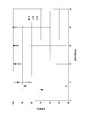
- FIG. 5 is a graph showing the correlation between the accuracy with respect to the radius of the set shape (set radius) and the number of fibers of the reinforcing fiber bundle C when forming a ring shape using a conventional three-dimensional printing apparatus. .
- the accuracy is indicated by the ratio (%) of the actually formed ring-shaped radius (actual radius) to the set radius.
- the number of fibers in the reinforcing fiber bundle C is 1000 for 1K, 4000 for 4K, and 8000 for 8K.
- the accuracy of the actual radius tends to decrease as the set radius decreases.
- the accuracy of the actual radius tends to decrease.
- the above tendency indicates that the twist due to the difference between the inner diameter and the outer diameter of the filament F increases as the set radius decreases.
- the twist amount is increased as the set radius is decreased, and the twist amount is decreased as the set radius is increased.
- the twist amount is preferably set to 1 / r [rad / m].
- the twist amount is increased, so that twisting of the filament F can be prevented and more accurate three-dimensional printing is possible.
- the twist adjusting unit 6 can adjust both the presence / absence of twist and the amount of twist, but the present invention is not limited to this.
- the twist adjusting unit 6 may adjust only the presence or absence of twist formation.
- control apparatus 5 employ
- this invention is based on this. It is not limited.
- a sensor that detects the deflection of the filament F is provided, and the control device 5 may be configured to twist the filament F when the deflection of the filament F is detected when the three-dimensional structure is formed. is there.
- the three-dimensional printing apparatus 1 includes a step of generating the filament F by impregnating the reinforcing fiber bundle C with the thermoplastic resin P.
- the three-dimensional printing apparatus 1 may supply a filament F produced by impregnating a reinforcing fiber bundle C with a thermoplastic resin P in advance. In this case, as shown in the second embodiment, the three-dimensional printing apparatus 1 can twist the filament F by heating and twisting the filament F.
- the reinforcing fiber bundle C or the filament F in a twisted state may be supplied to the three-dimensional printing apparatus.
- the twisting means of the three-dimensional printing apparatus adjusts the twist amount by rotating the reinforcing fiber bundle C or the filament F in the untwisting direction or the twisting direction. In this case, when forming a shape with many curved surfaces, the step of adjusting the twist amount can be easily and quickly performed.
- the three-dimensional printing apparatus may not be provided with the platform 3 and may operate in a state that is not horizontal with respect to the base of the shape to be formed.
- the three-dimensional printing apparatus 1 may include a robot arm for driving the printer head 4, and the printer head may be moved by the robot arm. In this case, the robot arm can move the printer head in the three-dimensional direction.
- the twist that is gradually accumulated in the filament inside the three-dimensional printing apparatus can be eliminated by twisting the filament with the twist adjusting unit.
Landscapes
- Engineering & Computer Science (AREA)
- Chemical & Material Sciences (AREA)
- Materials Engineering (AREA)
- Manufacturing & Machinery (AREA)
- Mechanical Engineering (AREA)
- Optics & Photonics (AREA)
- Physics & Mathematics (AREA)
- Ceramic Engineering (AREA)
- Civil Engineering (AREA)
- Composite Materials (AREA)
- Structural Engineering (AREA)
- Textile Engineering (AREA)
- Moulding By Coating Moulds (AREA)
Abstract
繊維束(C)に樹脂(P)を含浸させた線状のフィラメント(F)を連続して吐出可能な3次元プリンティング装置(1)であって、上記フィラメント(F)の全体の撚り量あるいは上記繊維束(C)の撚り量を変更可能な撚り手段(6)を備える。
Description
本発明は、3次元プリンティング装置に関する。
本願は、2017年2月15日に、日本に出願された特願2017-025745号に基づき優先権を主張し、その内容をここに援用する。
本願は、2017年2月15日に、日本に出願された特願2017-025745号に基づき優先権を主張し、その内容をここに援用する。
例えば、特許文献1には、熱溶解により樹脂フィラメントを溶融させ、溶融した樹脂フィラメントを積層することにより立体構造物を成形する3Dプリンタ(3次元プリンティング装置)が記載されている。このような3Dプリンタにおいて、樹脂を炭素繊維やガラス繊維などの繊維に含浸させたフィラメントを用いることにより、成形される立体構造物の強度を増加させることが考えられている。
しかしながら、繊維に樹脂を含浸させたフィラメントを用いる3次元プリンティング装置では、湾曲部分等を成形するために、連続するフィラメントをプラットホーム等の上で湾曲するように吐出する場合がある。フィラメントを湾曲するように配置していくと、徐々にフィラメントに捻じれが生じ、フィラメント内部の繊維も捩ることになる。このようにフィラメント内部の繊維が捻じれると、繊維の復元力によりフィラメントが意図せず変形し、設計通りの形状の立体構造物を作製できない可能性がある。
本発明は、上述する問題点に鑑みてなされたもので、繊維に樹脂を含浸させたフィラメントを用いる3次元プリンティング装置において、繊維の捩れによるフィラメントの変形を抑制し、設計通りの立体構造物を作製可能とすることを目的とする。
上記目的を達成するために、本発明では、第1の態様として、繊維束に樹脂を含浸させた線状のフィラメントを連続して吐出可能な3次元プリンティング装置であって、上記フィラメントの全体の撚り量あるいは上記繊維束の撚り量を変更可能な撚り手段を備える。
第2の態様として、上記繊維側に上記樹脂を含浸させる含浸手段と、上記含浸手段から上記フィラメントを引き出す引出手段と、上記引出手段にて引き出された上記フィラメントを被吐出対象物に押し付ける押付手段と備える。
第3の態様として、上記撚り手段は、上記含浸手段に供給される前の上記繊維束を撚る繊維束撚り機構である。
第4の態様として、上記繊維束撚り機構は、上記含浸手段に供給される繊維束が巻回された繊維束用ボビンを回動させることにより上記繊維束を撚る。
第5の態様として、上記撚り手段は、上記含浸手段から排出された上記フィラメントの全体を撚るフィラメント撚り機構である。
第6の態様として、上記押付手段は、ヒータが内蔵されたローラである。
第7の態様として、上記撚り手段は、作成対象となる立体構造物の設計形状に基づいて、上記設計形状のうち曲率が大きい部位に対しては上記撚り量が大きくなるように調節し、上記設計形状のうち曲率が小さい部位に対しては上記撚り量が小さくなるように調節する。
第8の態様として、上記撚り手段は、曲面状の部位を形成する場合に、上記繊維束の繊維本数が多いほど撚り量が大きくなるように調節する。
本発明によれば、3次元プリンティング装置は、繊維束の撚り量を調節可能な撚り調節部を備えている。したがって、曲面状の部位を成形する際に繊維束を撚ることにより、曲面の内側に配置される繊維と外側に配置される繊維との所要長さの差が解消することができ、フィラメントを湾曲させることにより生じる繊維の捩れを解消することができる。したがって、本発明によれば、繊維に樹脂を含浸させたフィラメントを用いる3次元プリンティング装置において、繊維の捩れによるフィラメントの変形を抑制し、設計通りの立体構造物を作製可能とすることができる。また、フィラメントを用いて撚り調節部を駆動させずに立体構造物を作成した際に、3次元プリンティング装置の内部のフィラメントに次第に蓄積される撚りを、撚り調節部によりフィラメントを撚ることで、解消することができる。
以下、図面を参照して、本発明に係る3次元プリンティング装置の一実施形態について説明する。
[第1実施形態]
本実施形態の3次元プリンティング装置は、樹脂(熱可塑性樹脂P)と強化繊維束Cを含む線状(糸状)のフィラメントFを板状のプラットホームの上に連続的に配置することによって構造物を形成する装置である。具体的には、例えば、フィラメントFを軟化状態でプラットホームに積層した後、固化させることによって、三次元構造物を形成する装置(3次元プリンティング装置)である。被吐出対象物としては、プラットホームの他に、積層されたフィラメントF(構造物)も含まれる。
構造物の原材料となるフィラメントFは、例えば、PLA樹脂(polylactic acid、ポリ乳酸)、ABS樹脂、ナイロン樹脂などの熱可塑性樹脂Pに、炭素繊維やガラス繊維などの強化繊維束Cを含浸させ、線状に形成したものである。
図1に示すように、3次元プリンティング装置1は、ケーシング2と、ケーシング2内に配置されたプラットホーム3と、プラットホーム3にフィラメントFを供給するプリンタヘッド4と、制御装置5と、撚り調節部6(繊維束撚り機構)と、ボビン7と、プラットホーム駆動装置8と、ヘッダ駆動装置9と、を有している。図1において、矢印Zは鉛直方向(上下方向)を示し、矢印Xは水平方向の一方向を示し、矢印Yは水平方向であってZ方向及びX方向に直交する方向を示している。
ケーシング2は、少なくとも前面が開口された箱形状の筐体である。プラットホーム3は、ケーシング2の底面2aと平行な矩形板である。プラットホーム3は、プリンタヘッド4の下方であって、ケーシング2の底部近傍に配置されている。プラットホーム3は、プラットホーム駆動装置8によって鉛直方向Zに上下移動可能に駆動される。また、プラットホーム3には、配置されたフィラメントFを加熱するためのプラットホーム加熱装置(図示せず)が設けられている。換言すれば、プラットホーム3は、プラットホーム3上に配置されたフィラメントFを加熱する機能を有している。
プリンタヘッド4は、ヒータ4aと、上側フィラメント引出装置4b(引出手段)と、切断装置4cと、下側フィラメント引出装置4d(引出手段)と、押付ローラ4e(押付手段)とを有している。また、プリンタヘッド4には、強化繊維束Cが通る繊維通路R1と、熱可塑性樹脂Pが通る樹脂通路R2と、繊維通路R1及び樹脂通路R2と接続され、加熱されることにより熱可塑性樹脂Pが強化繊維束Cに含浸される含浸通路R3とが形成されている。
ヒータ4aは、含浸通路R3の通路側方に設けられ、含浸通路R3内の熱可塑性樹脂Pを加熱することにより溶融させている。ヒータ4a及び含浸通路R3は、本発明における含浸手段を構成している。上側フィラメント引出装置4bは、2つのローラにより構成され、熱可塑性樹脂Pが含浸されたフィラメントFを挟み込んでZ方向下側に向けて送り出す。切断装置4cは、上側フィラメント引出装置4bの下方に設けられ、引き出されたフィラメントFを任意の位置で切断する装置である。下側フィラメント引出装置4dは、切断装置4cの下方に設けられ、2つのローラにより構成されており、フィラメントFをプラットホーム3に向けて送り出す装置である。押付ローラ4eは、ヒータを内蔵し、吐出されたフィラメントFを加熱しつつ、プラットホーム3に向けて押し付けるローラである。
制御装置5は、プリンタヘッド4、及びプラットホーム3の制御を行うコンピュータである。具体的には、制御装置5は、プリンタヘッド4などを制御する制御プログラムや、構造物の3Dデータなどを記憶する記憶装置や、制御プログラムを実行するためのプロセッサを有する装置である。
撚り調節部6は、ボビン7のうち、後述する繊維ボビン7aにおいて、強化繊維束Cに対して撚りを形成させる装置である。撚り調節部6は、例えば、繊維ボビン7aをZ方向に沿う回転軸で回転させることで、強化繊維束Cに撚りを形成させる。また、撚り調節部6は、制御装置5からの指示に基づいて、撚りの有無及び撚り量を調節することが可能である。具体的には、撚り調節部6は、制御装置5に制御されることにより、プラットホーム3において湾曲する部分に発生する繊維の撚れを解消するように繊維ボビン7aを回転させる。
ボビン7は、強化繊維束Cが巻回された繊維ボビン7a(繊維束用ボビン)と、熱可塑性樹脂Pが巻回された樹脂ボビン7bとにより構成されている。また、ボビン7は、不図示の回転機構によりX方向に沿う回転軸で回転され、巻回された強化繊維束C及び熱可塑性樹脂PをZ方向下側へと垂下させている。強化繊維束C及び熱可塑性樹脂Pは、ボビン7からプリンタヘッド4へと供給される。これらのボビン7は、プリンタヘッド4と共に移動される。
プラットホーム駆動装置8は、制御装置5からの指示に基づいて、プラットホーム3をZ方向において移動させる装置である。ヘッダ駆動装置9は、制御装置5からの指示に基づいて、プリンタヘッド4をX方向及びY方向へと移動させる装置である。ヘッダ駆動装置9は、プリンタヘッド4をプラットホーム3と平行な面上に沿う第一方向(X軸方向)に移動させるX軸駆動装置9aと、プリンタヘッド4をプラットホーム3と平行な面上に沿う第一方向と直交する第二方向(Y軸方向)に移動させるY軸駆動装置9bと、から構成されている。X軸駆動装置9aとY軸駆動装置9bとは、例えば、ステッピングモータと、ボールねじなどの直動機構を組み合わせた、所定の駆動装置を用いることができる。
このような本実施形態における3次元プリンティング装置1が駆動されると、繊維ボビン7a及び樹脂ボビン7bが回転され、繊維通路R1及び樹脂通路R2へと強化繊維束C及び熱可塑性樹脂Pが供給される。熱可塑性樹脂Pは、ヒータ4aにより溶融され、強化繊維束Cに含浸されることで、フィラメントFとなる。さらに、フィラメントFは、上側フィラメント引出装置4b及び下側フィラメント引出装置4dにより、Z方向下側へと搬送され、プラットホーム3上へと到達する。そして、フィラメントFは、押付ローラ4eによりプラットホーム3またはプラットホーム3に積層されたフィラメントFに対して押し付けられることで、内部の気泡が潰される。また、吐出されたフィラメントFがプラットホーム3に積層されたフィラメントFに対して押し付けられる場合には、押付ローラ4eにより互いに押し付けられることで、フィラメントF同士が密着させられる。なお、設計形状を記憶する制御装置5は、プラットホーム駆動装置8及びヘッダ駆動装置9を駆動させることによりフィラメントFが設計形状に沿って積層されるように、プラットホーム3及びプリンタヘッド4を適宜移動させる。
また、曲面を形成する場合には、制御装置5が撚り調節部6に指示することにより、繊維ボビン7aから供給される強化繊維束Cに撚りが加えられる。そして、撚りが加えられた強化繊維束Cに熱可塑性樹脂Pが含浸されたフィラメントFは、図2に示すように、設計形状に沿って湾曲して配置される。これにより、曲面状の部位における内側と外側との曲率の違いに基づく所要長さの差を解消することができ、フィラメントFを湾曲させることにより生じる繊維の捩れを解消することができる。したがって、強化繊維束Cに熱可塑性樹脂Pを含浸させたフィラメントFを用いる3次元プリンティング装置1において、繊維の捩れによるフィラメントFの変形を抑制し、設計通りの立体構造物を作製可能とすることができる。また、撚り調節部6を駆動させずに立体構造物を作成する際に、3次元プリンティング装置1の内部においてフィラメントFのねじれが次第に蓄積される場合がある。このような場合に、撚り調節部6によりフィラメントFを撚ることで、解消することができる。
なお、曲面状の部位と平面状の部位とが連続する設計形状の場合には、曲面状の部位を形成する強化繊維束Cの部位のみに撚りを加え、平面状の部位を形成する際には強化繊維束Cはストレートな状態とする。これにより、成形された立体構造物は、曲面状の部位のみにおいて強化繊維束Cに撚りが加えられた状態となり、平面状の部位では強化繊維束Cが直線状とされることで強度を保持することができる。また、制御装置5は、設計形状に基づいて、曲率の大きい部位については撚り量を大きい繊維束、すなわち多く撚りが加えられた繊維束を供給させ、曲率の小さい部位については撚り量の小さい繊維束を供給させることができる。
また、本実施形態によれば、撚った状態の強化繊維束Cに対して熱可塑性樹脂Pを含浸させる。このため、溶融した熱可塑性樹脂Pは、強化繊維束Cに絡みやすくなり、強化繊維束Cに含浸しやすくなる。
さらに、本実施形態によれば、上側フィラメント引出装置4b及び下側フィラメント引出装置4dにより、含浸通路R3の下側でフィラメントFを引き出している。これにより、本実施形態の3次元プリンティング装置1は、フィラメントFを吐出するための吐出ノズルを不要とし、フィラメントFが吐出ノズルに詰まることがない。また、3次元プリンティング装置1は、押付ローラ4eを備えることにより、成形された立体構造物に気泡が混入することを防止すると共に、積層されるフィラメントF同士を密着させることができる。
また、本実施形態においては、撚り調節部6は、繊維ボビン7aをZ方向に沿う回転軸で回転させることにより、強化繊維束Cに撚りを加えている。したがって、3次元プリンティング装置1は、複雑な構成を設けることなく強化繊維束Cの撚りを調節することができる。
[第2実施形態]
次に、上記第1実施形態の変形例を第2実施形態として説明する。なお、第1実施形態と同一の機能を有する構成については、符号を同一としている。
次に、上記第1実施形態の変形例を第2実施形態として説明する。なお、第1実施形態と同一の機能を有する構成については、符号を同一としている。
本実施形態における3次元プリンティング装置1は、図3に示すように、繊維ボビン7aを回転させる撚り調節部6を有さず、含浸手段から排出されたフィラメントFに撚りを加える構成とされている。具体的には、プリンタヘッド4は、下側フィラメント引出装置4dの下方にさらに搬送ローラ4fを有している。また、3次元プリンティング装置1には、上側フィラメント引出装置4b及び搬送ローラ4fをZ方向に沿う回転軸で回転可能とする撚り調節部6A(フィラメント撚り機構)が設けられている。なお、下側フィラメント引出装置4dは、上側フィラメント引出装置4b及び搬送ローラ4fが回転される際に固定された状態を保持している。また、上側フィラメント引出装置4bの周囲にはヒータが設けられ、フィラメントFが加熱されるものとしてもよい。
このような本実施形態における3次元プリンティング装置1は、強化繊維束Cに熱可塑性樹脂Pが含浸された状態において、上側フィラメント引出装置4b及び搬送ローラ4fがZ方向に沿う回転軸で互いに反対方向に回転されることにより、上側フィラメント引出装置4bと搬送ローラ4fとの間においてフィラメントFに撚りが形成される。
撚りが加えられたフィラメントFは、図2に示すように、設計形状に沿って湾曲させて配置される。これにより、曲面状の部位における内側と外側との曲率の違いに基づく所要長さの差を解消することができ、フィラメントFを湾曲させることにより生じる繊維の捩れを解消することができる。したがって、強化繊維束Cに熱可塑性樹脂Pを含浸させたフィラメントFを用いる3次元プリンティング装置1において、繊維の捩れによるフィラメントFの変形を抑制し、設計通りの立体構造物を作製可能とすることができる。
また、フィラメントFに撚りを加えることにより、熱可塑性樹脂Pが移動して均一となることで、強化繊維束Cに熱可塑性樹脂Pが含浸される際に発生した含浸不良が改善する効果が得られる。
[第3実施形態]
次に、上記第1実施形態の別の変形例を第3実施形態として説明する。なお、第1実施形態と同一の機能を有する構成については、符号を同一としている。
次に、上記第1実施形態の別の変形例を第3実施形態として説明する。なお、第1実施形態と同一の機能を有する構成については、符号を同一としている。
図4は、本実施形態における3次元プリンティング装置においては、図4に示すように、上側フィラメント引出装置4b、下側フィラメント引出装置4d及び撚り調節部6を備えておらず、プリンタヘッド4に不図示の回転機構が設けられる構成とされる。これにより、プリンタヘッド4が回転することで、フィラメントFが撚られた状態でプリンタヘッド4より吐出される。したがって、プリンタヘッド4が本発明における撚り手段に相当する。
このような構成とすることにより、小型の3次元プリンティング装置であり、撚り調節装置等を設けることが困難な場合でも、フィラメントFに撚りを形成することが可能である。
また、図5は、従来の3次元プリンティング装置を用いて環形状を形成する際の設定形状の半径(設定半径)に対する正確度と、強化繊維束Cの繊維本数との相関を示すグラフである。なお、正確度は、設定半径に対する実際に形成された環形状の半径(実半径)の割合(%)で示している。また、強化繊維束Cの繊維本数は、1Kが1000本、4Kが4000本、8Kが8000本を示している。
なお、図5のグラフに示すように、従来の3次元プリンティング装置では、設定半径が小さいほど、実半径の正確度が下がる傾向が見られる。また、強化繊維束Cの本数が多いほど、実半径の正確度が下がる傾向が見られる。上記の傾向は、設定半径が小さくなるほど、フィラメントFの内径と外径との差による捩れが大きくなることを示している。
したがって、本発明の3次元プリンティング装置1において、設定半径が小さいほど撚り量を大きくし、設定半径が大きいほど撚り量を小さくすることで、フィラメントFの捩れを防止でき、より正確な3次元プリントが可能となる。例えば、曲率半径r[m]の曲面をプリントする場合には、撚り量を1/r[rad/m]と設定することが良い。
さらに、本発明の3次元プリンティング装置1において、強化繊維束Cの本数が多いほど撚り量を大きくすることで、フィラメントFの捩れを防止でき、より正確な3次元プリントが可能となる。
以上、図面を参照しながら本発明の好適な実施形態について説明したが、本発明は上記実施形態に限定されるものではない。上述した実施形態において示した各構成部材の諸形状や組み合わせ等は一例であって、本発明の趣旨から逸脱しない範囲において設計要求等に基づき種々変更可能である。
上記実施形態においては、撚り調節部6は、撚りの形成の有無及び撚り量の双方を調節可能としたが、本発明はこれに限定されない。撚り調節部6は、撚りの形成の有無のみを調節するものとしてもよい。
上記実施形態においては、制御装置5は、設計形状に基づき、立体構造物の曲面状の部位について、強化繊維束CまたはフィラメントFに撚りを加える構成を採用しているが、本発明はこれに限定されない。例えば、フィラメントFの撓みを検出するセンサが設けられ、制御装置5は、立体構造物の成形時において、フィラメントFの撓みを検出した際に、フィラメントFに撚りを加える構成とすることも可能である。
また、上記実施形態においては、3次元プリンティング装置1は、熱可塑性樹脂Pを強化繊維束Cに含浸させてフィラメントFを生成する工程を含むものとしたが、本発明はこれに限定されない。3次元プリンティング装置1は、予め熱可塑性樹脂Pが強化繊維束Cに含浸されて製造されたフィラメントFを供給してもよい。この場合、3次元プリンティング装置1は、上記第2実施形態に示すように、フィラメントFを加熱すると共に撚りを加えることで、フィラメントFを撚ることができる。
また、3次元プリンティング装置には、撚りが加えられた状態の強化繊維束CまたはフィラメントFが供給されてもよい。3次元プリンティング装置の撚り手段は、撚りを解く方向または撚る方向に強化繊維束CまたはフィラメントFを回転させることで、撚り量を調節する。この場合、曲面の多い形状を形成する際に、撚り量を調節する工程を容易にかつ素早く行うことができる。
また、3次元プリンティング装置は、プラットホーム3を備えず、形成される形状の土台に対して水平でない状態で動作するものとしてもよい。さらに、3次元プリンティング装置1は、プリンタヘッド4を駆動させるためのロボットアームを備え、ロボットアームによりプリンタヘッドを移動させてもよい。この場合、ロボットアームは、プリンタヘッドを三次元方向に移動させることが可能である。
本発明によれば、3次元プリンティング装置の内部のフィラメントに次第に蓄積される撚りを、撚り調節部によりフィラメントを撚ることで、解消することができる。
1……3次元プリンティング装置
4……プリンタヘッド
4a……ヒータ
4b……上側フィラメント引出装置
4c……切断装置
4d……下側フィラメント引出装置
4e……押付ローラ
4f……搬送ローラ
5……制御装置
6、6A……撚り調節部
4……プリンタヘッド
4a……ヒータ
4b……上側フィラメント引出装置
4c……切断装置
4d……下側フィラメント引出装置
4e……押付ローラ
4f……搬送ローラ
5……制御装置
6、6A……撚り調節部
Claims (12)
- 繊維束に樹脂を含浸させた線状のフィラメントを連続して吐出可能な3次元プリンティング装置であって、
前記フィラメントの全体の撚り量あるいは前記繊維束の撚り量を変更可能な撚り手段を備える3次元プリンティング装置。 - 前記繊維束に前記樹脂を含浸させる含浸手段と、
前記含浸手段から前記フィラメントを引き出す引出手段と、
前記引出手段にて引き出された前記フィラメントを被吐出対象物に押し付ける押付手段と
を備える請求項1記載の3次元プリンティング装置。 - 前記撚り手段は、前記含浸手段に供給される前の前記繊維束を撚る繊維束撚り機構である請求項2記載の3次元プリンティング装置。
- 前記繊維束撚り機構は、前記含浸手段に供給される繊維束が巻回された繊維束用ボビンを回動させることにより前記繊維束を撚る請求項3記載の3次元プリンティング装置。
- 前記撚り手段は、前記含浸手段から排出された前記フィラメントの全体を撚るフィラメント撚り機構である請求項2記載の3次元プリンティング装置。
- 前記押付手段は、ヒータが内蔵されたローラである請求項2~5のいずれか一項に記載の3次元プリンティング装置。
- 前記撚り手段は、作成対象となる立体構造物の設計形状に基づいて、前記設計形状のうち曲率が大きい部位に対しては前記撚り量が大きくなるように調節し、前記設計形状のうち曲率が小さい部位に対しては前記撚り量が小さくなるように調節する請求項1~5のいずれか一項に記載の3次元プリンティング装置。
- 前記撚り手段は、作成対象となる立体構造物の設計形状に基づいて、前記設計形状のうち曲率が大きい部位に対しては前記撚り量が大きくなるように調節し、前記設計形状のうち曲率が小さい部位に対しては前記撚り量が小さくなるように調節する請求項6に記載の3次元プリンティング装置。
- 前記撚り手段は、曲面状の部位を形成する場合に、前記繊維束の繊維本数が多いほど撚り量が大きくなるように調節する請求項1~5のいずれか一項に記載の3次元プリンティング装置。
- 前記撚り手段は、曲面状の部位を形成する場合に、前記繊維束の繊維本数が多いほど撚り量が大きくなるように調節する請求項6に記載の3次元プリンティング装置。
- 前記撚り手段は、曲面状の部位を形成する場合に、前記繊維束の繊維本数が多いほど撚り量が大きくなるように調節する請求項7に記載の3次元プリンティング装置。
- 前記撚り手段は、曲面状の部位を形成する場合に、前記繊維束の繊維本数が多いほど撚り量が大きくなるように調節する請求項8に記載の3次元プリンティング装置。
Priority Applications (3)
| Application Number | Priority Date | Filing Date | Title |
|---|---|---|---|
| US16/485,711 US11472109B2 (en) | 2017-02-15 | 2018-02-13 | Three-dimensional printing apparatus |
| JP2018568518A JP6969753B2 (ja) | 2017-02-15 | 2018-02-13 | 3次元プリンティング装置 |
| EP18753645.3A EP3584062A4 (en) | 2017-02-15 | 2018-02-13 | THREE-DIMENSIONAL PRINTING DEVICE |
Applications Claiming Priority (2)
| Application Number | Priority Date | Filing Date | Title |
|---|---|---|---|
| JP2017-025745 | 2017-02-15 | ||
| JP2017025745 | 2017-02-15 |
Publications (1)
| Publication Number | Publication Date |
|---|---|
| WO2018151074A1 true WO2018151074A1 (ja) | 2018-08-23 |
Family
ID=63170585
Family Applications (1)
| Application Number | Title | Priority Date | Filing Date |
|---|---|---|---|
| PCT/JP2018/004817 WO2018151074A1 (ja) | 2017-02-15 | 2018-02-13 | 3次元プリンティング装置 |
Country Status (4)
| Country | Link |
|---|---|
| US (1) | US11472109B2 (ja) |
| EP (1) | EP3584062A4 (ja) |
| JP (1) | JP6969753B2 (ja) |
| WO (1) | WO2018151074A1 (ja) |
Cited By (8)
| Publication number | Priority date | Publication date | Assignee | Title |
|---|---|---|---|---|
| JP2019081292A (ja) * | 2017-10-30 | 2019-05-30 | 株式会社Ihi | 三次元造形物製造装置及び三次元造形物製造方法 |
| CN111186138A (zh) * | 2020-04-13 | 2020-05-22 | 北京化工大学 | 一种连续纤维熔融浸渍的3d打印装置及工艺 |
| EP3695951A1 (en) * | 2019-02-18 | 2020-08-19 | Fuji Xerox Co., Ltd | Shaping apparatus |
| JP2020131699A (ja) * | 2019-02-18 | 2020-08-31 | 富士ゼロックス株式会社 | 造形装置 |
| JP2020175628A (ja) * | 2019-04-22 | 2020-10-29 | 株式会社Ihi | 三次元造形装置及び三次元造形方法 |
| JP2021091190A (ja) * | 2019-12-12 | 2021-06-17 | 富士フイルムビジネスイノベーション株式会社 | 造形装置 |
| JP7392397B2 (ja) | 2019-01-31 | 2023-12-06 | 富士フイルムビジネスイノベーション株式会社 | 造形装置 |
| JP7484288B2 (ja) | 2020-03-24 | 2024-05-16 | 富士フイルムビジネスイノベーション株式会社 | 造形装置 |
Families Citing this family (8)
| Publication number | Priority date | Publication date | Assignee | Title |
|---|---|---|---|---|
| CN111169000A (zh) * | 2018-11-12 | 2020-05-19 | 三纬国际立体列印科技股份有限公司 | 立体打印装置 |
| CN111361151B (zh) * | 2020-03-17 | 2021-04-27 | 重庆市美客无双智能科技有限公司 | 一种混色3d打印喷头组件以及混色方法 |
| CN111645228A (zh) * | 2020-06-12 | 2020-09-11 | 上海大学 | 一种加捻连续天然纤维预浸料的制备方法 |
| CN111688193B (zh) * | 2020-06-13 | 2021-05-14 | 西安交通大学 | 可控偏置连续纤维增强复合材料的直写3d打印装置及方法 |
| CN114290679B (zh) * | 2021-12-30 | 2023-10-03 | 浙江闪铸集团有限公司 | 一种3d打印机进丝结构及其调试方法 |
| IT202200009980A1 (it) * | 2022-05-13 | 2023-11-13 | Univ Della Calabria | Dispositivo di estrusione e stampante 3D |
| CN115091757B (zh) * | 2022-06-21 | 2024-01-05 | 深圳市创想三维科技股份有限公司 | 3d打印自动切换料装置及3d打印机 |
| DE102022125491A1 (de) * | 2022-10-04 | 2024-04-04 | Simona Aktiengesellschaft | Vorrichtung und Verfahren zur additiven Bauteilherstellung |
Citations (7)
| Publication number | Priority date | Publication date | Assignee | Title |
|---|---|---|---|---|
| WO2015182675A1 (ja) * | 2014-05-27 | 2015-12-03 | 学校法人日本大学 | 三次元プリンティングシステム、三次元プリンティング方法、成形装置、繊維入りオブジェクト及びその製造方法 |
| WO2015198706A1 (ja) * | 2014-06-26 | 2015-12-30 | 株式会社リコー | 三次元造形方法、及び三次元造形装置 |
| JP2016501136A (ja) | 2012-11-09 | 2016-01-18 | エボニック インダストリーズ アクチエンゲゼルシャフトEvonik Industries AG | 多色の押出し成形3d印刷 |
| WO2016129613A1 (ja) * | 2015-02-10 | 2016-08-18 | ユニチカ株式会社 | 造形材料 |
| JP2016531020A (ja) * | 2013-07-17 | 2016-10-06 | マークフォーゲット インコーポレイテッドMarkforged, Inc. | 繊維強化による積層造形用装置 |
| JP2017025745A (ja) | 2015-07-18 | 2017-02-02 | 利次 鼻田 | フライホイール |
| JP2017128072A (ja) * | 2016-01-22 | 2017-07-27 | 国立大学法人岐阜大学 | 立体構造物の製造方法および3dプリンタ用フィラメント |
Family Cites Families (16)
| Publication number | Priority date | Publication date | Assignee | Title |
|---|---|---|---|---|
| US5134569A (en) * | 1989-06-26 | 1992-07-28 | Masters William E | System and method for computer automated manufacturing using fluent material |
| US6934600B2 (en) * | 2002-03-14 | 2005-08-23 | Auburn University | Nanotube fiber reinforced composite materials and method of producing fiber reinforced composites |
| US9511445B2 (en) * | 2014-12-17 | 2016-12-06 | Aeroprobe Corporation | Solid state joining using additive friction stir processing |
| US8875976B2 (en) * | 2005-09-26 | 2014-11-04 | Aeroprobe Corporation | System for continuous feeding of filler material for friction stir welding, processing and fabrication |
| ES2373640T3 (es) | 2007-06-12 | 2012-02-07 | Hexcel Reinforcements | Procedimiento de fabricación de un material compuesto en el que al menos se coloca un hilo retorcido y el material compuesto que se obtiene de este modo. |
| US9126365B1 (en) * | 2013-03-22 | 2015-09-08 | Markforged, Inc. | Methods for composite filament fabrication in three dimensional printing |
| WO2014197732A2 (en) * | 2013-06-05 | 2014-12-11 | Markforged, Inc. | Methods for fiber reinforced additive manufacturing |
| US9481131B2 (en) | 2013-07-18 | 2016-11-01 | Mitsubishi Electric Research Laboratories, Inc. | Method and apparatus for printing 3D objects using additive manufacturing and material extruder with translational and rotational axes |
| US20160243762A1 (en) | 2013-11-15 | 2016-08-25 | Fleming Robert J | Automated design, simulation, and shape forming process for creating structural elements and designed objects |
| US20160297104A1 (en) * | 2013-11-19 | 2016-10-13 | Guill Tool & Engineering | Coextruded, multilayer and multicomponent 3d printing inputs field |
| US9796140B2 (en) * | 2014-06-19 | 2017-10-24 | Autodesk, Inc. | Automated systems for composite part fabrication |
| CN104085112B (zh) * | 2014-07-11 | 2016-08-31 | 东莞中国科学院云计算产业技术创新与育成中心 | 一种3d打印机喷头及其速度和精度调控方法 |
| ES2894037T3 (es) | 2014-12-12 | 2022-02-11 | Fund Eurecat | Procedimiento para fabricar una pieza de material compuesto |
| US10195784B2 (en) * | 2015-07-31 | 2019-02-05 | The Boeing Company | Systems for additively manufacturing composite parts |
| US10232551B2 (en) * | 2016-04-15 | 2019-03-19 | Cc3D Llc | Head and system for continuously manufacturing composite hollow structure |
| JP2020152068A (ja) * | 2019-03-22 | 2020-09-24 | 富士ゼロックス株式会社 | 造形装置 |
-
2018
- 2018-02-13 WO PCT/JP2018/004817 patent/WO2018151074A1/ja unknown
- 2018-02-13 EP EP18753645.3A patent/EP3584062A4/en not_active Withdrawn
- 2018-02-13 JP JP2018568518A patent/JP6969753B2/ja active Active
- 2018-02-13 US US16/485,711 patent/US11472109B2/en active Active
Patent Citations (7)
| Publication number | Priority date | Publication date | Assignee | Title |
|---|---|---|---|---|
| JP2016501136A (ja) | 2012-11-09 | 2016-01-18 | エボニック インダストリーズ アクチエンゲゼルシャフトEvonik Industries AG | 多色の押出し成形3d印刷 |
| JP2016531020A (ja) * | 2013-07-17 | 2016-10-06 | マークフォーゲット インコーポレイテッドMarkforged, Inc. | 繊維強化による積層造形用装置 |
| WO2015182675A1 (ja) * | 2014-05-27 | 2015-12-03 | 学校法人日本大学 | 三次元プリンティングシステム、三次元プリンティング方法、成形装置、繊維入りオブジェクト及びその製造方法 |
| WO2015198706A1 (ja) * | 2014-06-26 | 2015-12-30 | 株式会社リコー | 三次元造形方法、及び三次元造形装置 |
| WO2016129613A1 (ja) * | 2015-02-10 | 2016-08-18 | ユニチカ株式会社 | 造形材料 |
| JP2017025745A (ja) | 2015-07-18 | 2017-02-02 | 利次 鼻田 | フライホイール |
| JP2017128072A (ja) * | 2016-01-22 | 2017-07-27 | 国立大学法人岐阜大学 | 立体構造物の製造方法および3dプリンタ用フィラメント |
Non-Patent Citations (1)
| Title |
|---|
| See also references of EP3584062A4 |
Cited By (12)
| Publication number | Priority date | Publication date | Assignee | Title |
|---|---|---|---|---|
| JP2019081292A (ja) * | 2017-10-30 | 2019-05-30 | 株式会社Ihi | 三次元造形物製造装置及び三次元造形物製造方法 |
| JP7392397B2 (ja) | 2019-01-31 | 2023-12-06 | 富士フイルムビジネスイノベーション株式会社 | 造形装置 |
| EP3695951A1 (en) * | 2019-02-18 | 2020-08-19 | Fuji Xerox Co., Ltd | Shaping apparatus |
| JP2020131699A (ja) * | 2019-02-18 | 2020-08-31 | 富士ゼロックス株式会社 | 造形装置 |
| JP7388075B2 (ja) | 2019-02-18 | 2023-11-29 | 富士フイルムビジネスイノベーション株式会社 | 造形装置 |
| JP2020175628A (ja) * | 2019-04-22 | 2020-10-29 | 株式会社Ihi | 三次元造形装置及び三次元造形方法 |
| JP7207131B2 (ja) | 2019-04-22 | 2023-01-18 | 株式会社Ihi | 三次元造形装置及び三次元造形方法 |
| JP2021091190A (ja) * | 2019-12-12 | 2021-06-17 | 富士フイルムビジネスイノベーション株式会社 | 造形装置 |
| JP7434869B2 (ja) | 2019-12-12 | 2024-02-21 | 富士フイルムビジネスイノベーション株式会社 | 造形装置 |
| JP7484288B2 (ja) | 2020-03-24 | 2024-05-16 | 富士フイルムビジネスイノベーション株式会社 | 造形装置 |
| CN111186138A (zh) * | 2020-04-13 | 2020-05-22 | 北京化工大学 | 一种连续纤维熔融浸渍的3d打印装置及工艺 |
| CN111186138B (zh) * | 2020-04-13 | 2021-04-23 | 北京化工大学 | 一种连续纤维熔融浸渍的3d打印装置及工艺 |
Also Published As
| Publication number | Publication date |
|---|---|
| EP3584062A4 (en) | 2020-11-25 |
| JP6969753B2 (ja) | 2021-11-24 |
| US11472109B2 (en) | 2022-10-18 |
| US20200130276A1 (en) | 2020-04-30 |
| EP3584062A1 (en) | 2019-12-25 |
| JPWO2018151074A1 (ja) | 2019-12-12 |
Similar Documents
| Publication | Publication Date | Title |
|---|---|---|
| WO2018151074A1 (ja) | 3次元プリンティング装置 | |
| WO2017150186A1 (ja) | 3次元プリンティング装置及び3次元プリンティング方法 | |
| CN1173083C (zh) | 复丝开纤片的制造方法和制造装置 | |
| US11104120B2 (en) | Three-dimensional printing system, three-dimensional printing method, molding device, fiber-containing object, and production method thereof | |
| JP4933584B2 (ja) | 樹脂含浸処理された複数の配向を有する複合材料の製造法 | |
| WO2016039081A1 (ja) | 繊維強化熱可塑性樹脂テープの製造方法、および製造装置 | |
| US4964891A (en) | Programmably controlled fiber glass strand feeders and improved methods for making glass fiber mats | |
| JP6962492B1 (ja) | 繊維強化樹脂成形材料の製造方法及び繊維強化樹脂成形材料の製造装置 | |
| US11168190B2 (en) | Random mat and production method therefor, and fiber-reinforced resin molding material using random mat | |
| KR102406266B1 (ko) | 직물 복합 재료의 연속 제조 시스템 및 방법 | |
| EP0428063A1 (en) | Programmably controlled fibre glass strand feeders and improved methods for making glass fibre mats | |
| JP2014227288A5 (ja) | ||
| JP7247596B2 (ja) | 造形装置 | |
| JP7484288B2 (ja) | 造形装置 | |
| JP7392397B2 (ja) | 造形装置 | |
| JP2005219373A (ja) | 強化繊維の自動積層装置及び強化繊維プリフォームの製造方法 | |
| JP2020044772A (ja) | 造形装置 | |
| JP7484296B2 (ja) | 造形材接続装置及び造形装置 | |
| JP2020023069A (ja) | 造形装置 | |
| JP5917223B2 (ja) | 繊維束処理装置 | |
| KR102045902B1 (ko) | 섬유 연속 공급 장치 | |
| WO2023233884A1 (ja) | フィラメント及び造形物の製造方法 | |
| JP2020026062A (ja) | 造形装置 | |
| JP2020104473A (ja) | 含浸装置、造形装置 | |
| JPH1044253A (ja) | 繊維強化熱可塑性樹脂シートの製造方法 |
Legal Events
| Date | Code | Title | Description |
|---|---|---|---|
| 121 | Ep: the epo has been informed by wipo that ep was designated in this application |
Ref document number: 18753645 Country of ref document: EP Kind code of ref document: A1 |
|
| ENP | Entry into the national phase |
Ref document number: 2018568518 Country of ref document: JP Kind code of ref document: A |
|
| NENP | Non-entry into the national phase |
Ref country code: DE |
|
| ENP | Entry into the national phase |
Ref document number: 2018753645 Country of ref document: EP Effective date: 20190916 |