WO2018150508A1 - 回転機械 - Google Patents
回転機械 Download PDFInfo
- Publication number
- WO2018150508A1 WO2018150508A1 PCT/JP2017/005684 JP2017005684W WO2018150508A1 WO 2018150508 A1 WO2018150508 A1 WO 2018150508A1 JP 2017005684 W JP2017005684 W JP 2017005684W WO 2018150508 A1 WO2018150508 A1 WO 2018150508A1
- Authority
- WO
- WIPO (PCT)
- Prior art keywords
- magnet
- rotating shaft
- casing
- damping
- damping mechanism
- Prior art date
- Legal status (The legal status is an assumption and is not a legal conclusion. Google has not performed a legal analysis and makes no representation as to the accuracy of the status listed.)
- Ceased
Links
Images



Classifications
-
- F—MECHANICAL ENGINEERING; LIGHTING; HEATING; WEAPONS; BLASTING
- F04—POSITIVE - DISPLACEMENT MACHINES FOR LIQUIDS; PUMPS FOR LIQUIDS OR ELASTIC FLUIDS
- F04D—NON-POSITIVE-DISPLACEMENT PUMPS
- F04D29/00—Details, component parts, or accessories
- F04D29/66—Combating cavitation, whirls, noise, vibration or the like; Balancing
- F04D29/661—Combating cavitation, whirls, noise, vibration or the like; Balancing especially adapted for elastic fluid pumps
- F04D29/668—Combating cavitation, whirls, noise, vibration or the like; Balancing especially adapted for elastic fluid pumps damping or preventing mechanical vibrations
-
- F—MECHANICAL ENGINEERING; LIGHTING; HEATING; WEAPONS; BLASTING
- F04—POSITIVE - DISPLACEMENT MACHINES FOR LIQUIDS; PUMPS FOR LIQUIDS OR ELASTIC FLUIDS
- F04D—NON-POSITIVE-DISPLACEMENT PUMPS
- F04D17/00—Radial-flow pumps, e.g. centrifugal pumps; Helico-centrifugal pumps
- F04D17/08—Centrifugal pumps
- F04D17/10—Centrifugal pumps for compressing or evacuating
- F04D17/12—Multi-stage pumps
- F04D17/122—Multi-stage pumps the individual rotor discs being, one for each stage, on a common shaft and axially spaced, e.g. conventional centrifugal multi- stage compressors
-
- F—MECHANICAL ENGINEERING; LIGHTING; HEATING; WEAPONS; BLASTING
- F04—POSITIVE - DISPLACEMENT MACHINES FOR LIQUIDS; PUMPS FOR LIQUIDS OR ELASTIC FLUIDS
- F04D—NON-POSITIVE-DISPLACEMENT PUMPS
- F04D25/00—Pumping installations or systems
- F04D25/02—Units comprising pumps and their driving means
- F04D25/06—Units comprising pumps and their driving means the pump being electrically driven
- F04D25/0606—Units comprising pumps and their driving means the pump being electrically driven the electric motor being specially adapted for integration in the pump
-
- F—MECHANICAL ENGINEERING; LIGHTING; HEATING; WEAPONS; BLASTING
- F04—POSITIVE - DISPLACEMENT MACHINES FOR LIQUIDS; PUMPS FOR LIQUIDS OR ELASTIC FLUIDS
- F04D—NON-POSITIVE-DISPLACEMENT PUMPS
- F04D29/00—Details, component parts, or accessories
- F04D29/05—Shafts or bearings, or assemblies thereof, specially adapted for elastic fluid pumps
- F04D29/051—Axial thrust balancing
-
- F—MECHANICAL ENGINEERING; LIGHTING; HEATING; WEAPONS; BLASTING
- F04—POSITIVE - DISPLACEMENT MACHINES FOR LIQUIDS; PUMPS FOR LIQUIDS OR ELASTIC FLUIDS
- F04D—NON-POSITIVE-DISPLACEMENT PUMPS
- F04D29/00—Details, component parts, or accessories
- F04D29/05—Shafts or bearings, or assemblies thereof, specially adapted for elastic fluid pumps
- F04D29/056—Bearings
- F04D29/058—Bearings magnetic; electromagnetic
-
- F—MECHANICAL ENGINEERING; LIGHTING; HEATING; WEAPONS; BLASTING
- F16—ENGINEERING ELEMENTS AND UNITS; GENERAL MEASURES FOR PRODUCING AND MAINTAINING EFFECTIVE FUNCTIONING OF MACHINES OR INSTALLATIONS; THERMAL INSULATION IN GENERAL
- F16F—SPRINGS; SHOCK-ABSORBERS; MEANS FOR DAMPING VIBRATION
- F16F15/00—Suppression of vibrations in systems; Means or arrangements for avoiding or reducing out-of-balance forces, e.g. due to motion
- F16F15/02—Suppression of vibrations of non-rotating, e.g. reciprocating systems; Suppression of vibrations of rotating systems by use of members not moving with the rotating systems
- F16F15/022—Suppression of vibrations of non-rotating, e.g. reciprocating systems; Suppression of vibrations of rotating systems by use of members not moving with the rotating systems using dampers and springs in combination
-
- F—MECHANICAL ENGINEERING; LIGHTING; HEATING; WEAPONS; BLASTING
- F16—ENGINEERING ELEMENTS AND UNITS; GENERAL MEASURES FOR PRODUCING AND MAINTAINING EFFECTIVE FUNCTIONING OF MACHINES OR INSTALLATIONS; THERMAL INSULATION IN GENERAL
- F16F—SPRINGS; SHOCK-ABSORBERS; MEANS FOR DAMPING VIBRATION
- F16F15/00—Suppression of vibrations in systems; Means or arrangements for avoiding or reducing out-of-balance forces, e.g. due to motion
- F16F15/02—Suppression of vibrations of non-rotating, e.g. reciprocating systems; Suppression of vibrations of rotating systems by use of members not moving with the rotating systems
- F16F15/03—Suppression of vibrations of non-rotating, e.g. reciprocating systems; Suppression of vibrations of rotating systems by use of members not moving with the rotating systems using magnetic or electromagnetic means
-
- F—MECHANICAL ENGINEERING; LIGHTING; HEATING; WEAPONS; BLASTING
- F16—ENGINEERING ELEMENTS AND UNITS; GENERAL MEASURES FOR PRODUCING AND MAINTAINING EFFECTIVE FUNCTIONING OF MACHINES OR INSTALLATIONS; THERMAL INSULATION IN GENERAL
- F16F—SPRINGS; SHOCK-ABSORBERS; MEANS FOR DAMPING VIBRATION
- F16F15/00—Suppression of vibrations in systems; Means or arrangements for avoiding or reducing out-of-balance forces, e.g. due to motion
- F16F15/02—Suppression of vibrations of non-rotating, e.g. reciprocating systems; Suppression of vibrations of rotating systems by use of members not moving with the rotating systems
- F16F15/03—Suppression of vibrations of non-rotating, e.g. reciprocating systems; Suppression of vibrations of rotating systems by use of members not moving with the rotating systems using magnetic or electromagnetic means
- F16F15/035—Suppression of vibrations of non-rotating, e.g. reciprocating systems; Suppression of vibrations of rotating systems by use of members not moving with the rotating systems using magnetic or electromagnetic means by use of eddy or induced-current damping
-
- F—MECHANICAL ENGINEERING; LIGHTING; HEATING; WEAPONS; BLASTING
- F16—ENGINEERING ELEMENTS AND UNITS; GENERAL MEASURES FOR PRODUCING AND MAINTAINING EFFECTIVE FUNCTIONING OF MACHINES OR INSTALLATIONS; THERMAL INSULATION IN GENERAL
- F16F—SPRINGS; SHOCK-ABSORBERS; MEANS FOR DAMPING VIBRATION
- F16F15/00—Suppression of vibrations in systems; Means or arrangements for avoiding or reducing out-of-balance forces, e.g. due to motion
- F16F15/10—Suppression of vibrations in rotating systems by making use of members moving with the system
- F16F15/12—Suppression of vibrations in rotating systems by making use of members moving with the system using elastic members or friction-damping members, e.g. between a rotating shaft and a gyratory mass mounted thereon
-
- F—MECHANICAL ENGINEERING; LIGHTING; HEATING; WEAPONS; BLASTING
- F16—ENGINEERING ELEMENTS AND UNITS; GENERAL MEASURES FOR PRODUCING AND MAINTAINING EFFECTIVE FUNCTIONING OF MACHINES OR INSTALLATIONS; THERMAL INSULATION IN GENERAL
- F16F—SPRINGS; SHOCK-ABSORBERS; MEANS FOR DAMPING VIBRATION
- F16F15/00—Suppression of vibrations in systems; Means or arrangements for avoiding or reducing out-of-balance forces, e.g. due to motion
- F16F15/10—Suppression of vibrations in rotating systems by making use of members moving with the system
- F16F15/12—Suppression of vibrations in rotating systems by making use of members moving with the system using elastic members or friction-damping members, e.g. between a rotating shaft and a gyratory mass mounted thereon
- F16F15/1201—Suppression of vibrations in rotating systems by making use of members moving with the system using elastic members or friction-damping members, e.g. between a rotating shaft and a gyratory mass mounted thereon for damping of axial or radial, i.e. non-torsional vibrations
-
- F—MECHANICAL ENGINEERING; LIGHTING; HEATING; WEAPONS; BLASTING
- F04—POSITIVE - DISPLACEMENT MACHINES FOR LIQUIDS; PUMPS FOR LIQUIDS OR ELASTIC FLUIDS
- F04D—NON-POSITIVE-DISPLACEMENT PUMPS
- F04D17/00—Radial-flow pumps, e.g. centrifugal pumps; Helico-centrifugal pumps
- F04D17/08—Centrifugal pumps
- F04D17/10—Centrifugal pumps for compressing or evacuating
- F04D17/105—Centrifugal pumps for compressing or evacuating with double suction
-
- F—MECHANICAL ENGINEERING; LIGHTING; HEATING; WEAPONS; BLASTING
- F16—ENGINEERING ELEMENTS AND UNITS; GENERAL MEASURES FOR PRODUCING AND MAINTAINING EFFECTIVE FUNCTIONING OF MACHINES OR INSTALLATIONS; THERMAL INSULATION IN GENERAL
- F16C—SHAFTS; FLEXIBLE SHAFTS; ELEMENTS OR CRANKSHAFT MECHANISMS; ROTARY BODIES OTHER THAN GEARING ELEMENTS; BEARINGS
- F16C19/00—Bearings with rolling contact, for exclusively rotary movement
- F16C19/52—Bearings with rolling contact, for exclusively rotary movement with devices affected by abnormal or undesired conditions
- F16C19/527—Bearings with rolling contact, for exclusively rotary movement with devices affected by abnormal or undesired conditions related to vibration and noise
Definitions
- the present invention relates to a rotating machine.
- Compressor that is one of rotating machines has a casing, a rotating shaft, an impeller, a radial bearing, and a thrust bearing.
- the casing has a fluid inlet for introducing a fluid and a fluid outlet for guiding the fluid compressed by the impeller.
- the rotating shaft is accommodated in the casing and extends in the longitudinal direction of the casing.
- the impeller is provided at one end of the rotating shaft and rotates together with the rotating shaft.
- the impeller compresses the introduced fluid and guides the compressed fluid to the fluid outlet.
- the radial bearing is disposed so as to face the outer peripheral surface of the rotating shaft.
- the radial bearing rotatably supports the rotating shaft.
- the thrust bearing is provided on the other end side of the rotating shaft. The thrust bearing supports the thrust direction of the rotating shaft.
- Patent Document 1 discloses a thrust bearing for the purpose of suppressing displacement of the rotating shaft in the thrust direction.
- the thrust bearing disclosed in Patent Document 1 is arranged with a first permanent magnet disposed at the other end of the rotating shaft, and spaced apart from the first permanent magnet in the thrust direction, with respect to the first permanent magnet. And a second permanent magnet repelling.
- Patent Document 1 does not have a configuration for attenuating the vibration of the rotating shaft in the thrust direction. For this reason, there was a possibility that the vibration of the rotating shaft in the thrust direction could not be attenuated.
- the present invention provides a rotating machine capable of dampening the vibration of the rotating shaft in the thrust direction.
- a rotating machine includes a casing, a rotating shaft supported in a rotatable state in the casing and extending in a thrust direction, and a first magnet provided on the rotating shaft.
- a damping mechanism supported by the casing and disposed opposite to the first magnet in the thrust direction; and provided in the damping mechanism so as to face the first magnet in the thrust direction.
- a second magnet that repels the first magnet, wherein the damping mechanism attenuates the vibration of the second magnet in the thrust direction, and the second magnet moves the first magnet to the first magnet.
- a push-back portion that pushes back in the direction toward the magnet is included.
- the attenuation portion that attenuates the vibration of the second magnet in the thrust direction, it is possible to reduce the force acting in the thrust direction by the attenuation portion when the rotation shaft moves in the direction toward the attenuation mechanism. It becomes.
- the push-back part which gives the force which pushes back a 2nd magnet in the direction which goes to a 1st magnet
- the position of the movable part of an attenuation part is returned to the rotating shaft side (it returns to the position where an attenuation part functions) It is possible to repeatedly attenuate the force acting in the thrust direction. Therefore, the vibration of the rotating shaft in the thrust direction can be attenuated.
- the first magnet provided on the rotating shaft and the second magnet provided in the damping mechanism so as to face the first magnet and repelling the first magnet, It becomes possible to have the same function as connecting the first magnet and the second magnet with a spring in a non-contact state. Thereby, even when the rotating shaft vibrates in the thrust direction, it becomes possible to avoid the collision between the first magnet and the second magnet, so that damage to the first and second magnets can be suppressed. .
- the push-back portion may be an elastic body.
- the second magnet can be pushed back in the direction toward the first magnet.
- the damping section may be a viscous fluid damper.
- the attenuation unit may be an eddy current damper.
- the damping portion may be a frictional resistance imparting member.
- the attenuation portion may be a viscoelastic member.
- the viscoelastic member as the damping part, it is possible to attenuate the vibration of the rotating shaft in the thrust direction.
- one of the first and second magnets has a convex portion, and the other has a concave portion in which a part of the convex portion is accommodated.
- the convex portion and the concave portion may be arranged to face each other in the thrust direction.
- one of the first and second magnets has a convex portion
- the other has a concave portion in which a part of the convex portion is accommodated
- the convex portion and the concave portion are arranged to face each other in the thrust direction.
- the rotating machine includes an impeller provided at one end of the rotating shaft, and a plurality of support portions that support the damping mechanism with respect to the casing.
- the casing includes a fluid introduction portion that is disposed to face the impeller and introduces a fluid into the casing, and the damping mechanism is disposed in the fluid introduction portion and may be supported by the plurality of support members. Good.
- the rotating shaft includes a rotating shaft main body extending in the thrust direction, and the damping mechanism is provided on one end side of the rotating shaft main body. Also good.
- the rotating shaft may include a rotating shaft main body extending in the thrust direction, and the damping mechanisms may be provided at both ends of the rotating shaft main body, respectively.
- the damping mechanism is disposed so as to sandwich the rotating shaft main body in the extending direction of the rotating shaft main body (the direction in which the rotating shaft vibrates).
- the damping mechanism is disposed so as to sandwich the rotating shaft main body in the extending direction of the rotating shaft main body (the direction in which the rotating shaft vibrates).
- the rotating shaft includes a rotating shaft main body extending in the thrust direction and a thrust collar provided on the rotating shaft main body,
- the magnet, the second magnet, and the damping mechanism may be provided on both sides of the thrust collar in the thrust direction so as to sandwich the thrust collar from the thrust direction.
- three or more pairs of the damping mechanisms that sandwich the thrust collar may be arranged in the circumferential direction of the thrust collar.
- the thrust collar is prevented from being inclined with respect to the extending direction of the rotating shaft body.
- the vibration of the rotating shaft in the direction can be attenuated.
- the first impeller provided at one end of the rotating shaft the second impeller provided at the other end of the rotating shaft, A plurality of support portions that support the damping mechanism with respect to the casing, and the casing is disposed opposite to the first impeller and introduces a first fluid into the casing.
- a second fluid introduction portion that is disposed opposite to the second impeller and introduces a second fluid into the casing, and the damping mechanism includes the first fluid introduction portion and the second fluid introduction portion.
- the fluid introduction portions may be respectively supported by the plurality of support members.
- the vibration of the rotating shaft in the thrust direction can be attenuated.
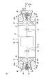
- FIG. 1 is a cross-sectional view showing a schematic configuration of a rotating machine according to the first embodiment of the present invention.
- X 1 direction shown in FIG. 1 is a direction toward the rotation axis body 13 from the first damping mechanism 31, X 2 direction toward the rotation axis body 13 from the second damping mechanism 32, X-direction X 1 direction and the X Thrust directions including the two directions (extending direction of the rotary shaft main body 13),
- O 1 indicates the axis of the rotary shaft 12 extending in the X direction (hereinafter referred to as “axis O 1 ”).
- FIG. 2 is a cross-sectional view schematically showing the rotary machine shown in FIG.
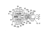
- FIG. 3 is an enlarged cross-sectional view of a portion surrounded by a region A in the rotary machine shown in FIG.
- FIG. 3 the same components as those shown in FIGS. 1 and 2 are denoted by the same reference numerals.
- the rotary machine 10 of the first embodiment includes a casing 11, a rotary shaft 12, a rotary drive unit 15, bearing support members 16 and 17, and radial bearings 19 and 21.
- the damping mechanism 32, two second magnets 33, and a plurality of support members 34 and 35 are provided.
- the casing 11 includes a first casing portion 36, second casing portions 37 and 38, third casing portions 41 and 42, and flow paths 43 and 44.
- the first casing portion 36 is a cylindrical member whose both ends are open ends.
- the first casing portion 36 extends in the X direction.
- a first flange portion 36 ⁇ / b> A is provided at one end of the first casing portion 36.
- a second flange portion 36 ⁇ / b> B is provided at the other end of the first casing portion 36.
- the second casing part 37 is fixed to the first flange part 36A.
- An opening 37 ⁇ / b> A into which a part of one end 13 ⁇ / b> A of the rotary shaft main body 13 is inserted is provided at the center of the second casing portion 37.
- the second casing portion 38 is fixed to the second flange portion 36B.
- An opening 38 ⁇ / b> A into which a part of the other end 13 ⁇ / b> B of the rotating shaft main body 13 is inserted is provided at the center of the second casing portion 38.
- the third casing part 41 includes a first fluid introduction part 45 and a support part 46.
- the first fluid introduction part 45 is a cylindrical member and extends in the X direction.
- the first fluid introduction part 45 has a space 45A in a cylindrical shape inside thereof.
- the space 45 ⁇ / b> A functions as an inlet for introducing a first fluid (for example, outside air) into the first impeller 26 disposed in the casing 11.
- the third casing portion 41 is provided at a position where the first fluid introduction portion 45 can accommodate one end portion 13 ⁇ / b> A of the rotary shaft main body 13.
- the support part 46 is provided at the other end of the first fluid introduction part 45.
- the shape of the support portion 46 is a shape that spreads outside the first fluid introduction portion 45.
- a part of the support portion 46 is in contact with the second casing portion 37.
- the support part 46 is fixed to the second casing part 37 with bolts or the like.
- the third casing part 42 includes a second fluid introduction part 48 and a support part 49.
- the second fluid introduction part 48 is a cylindrical member and extends in the X direction.
- the second fluid introduction part 48 has a space 48 ⁇ / b> A having a cylindrical shape inside thereof.
- the space 48 ⁇ / b> A functions as an inlet for introducing the second fluid into the second impeller 27 disposed in the casing 11.
- the second fluid for example, the first fluid that has passed through the first impeller 26 can be used.
- the third casing portion 42 is provided at a position where the second fluid introduction portion 48 can accommodate the other end portion 13B of the rotary shaft main body 13.
- the support portion 49 is provided at the other end of the second fluid introduction portion 48.
- the shape of the support portion 49 is a shape that spreads outside the second fluid introduction portion 48.
- a part of the support portion 49 is in contact with the second casing portion 38.
- the support portion 49 is fixed to the second casing portion 38 with bolts or the like.
- the flow path 43 is formed between the second casing part 37 and the third casing part 41.
- the first fluid derived from the first impeller 26 flows through the flow path 43.
- the flow path 44 is formed between the second casing portion 38 and the third casing portion 42.
- the second fluid derived from the second impeller 27 flows through the flow path 44.
- the rotating shaft 12 includes a rotating shaft main body 13.
- the rotating shaft main body 13 is accommodated in the casing 11 in a state extending in the X direction.
- the shape of the rotating shaft main body 13 can be a cylindrical shape, for example.
- the rotary shaft main body 13 is supported in a rotatable state by radial bearings 19 and 21.
- the rotating shaft main body 13 has one end 13A and the other end 13B.
- One end 13A includes one end 13Aa. A part of the one end portion 13 ⁇ / b> A including the one end 13 ⁇ / b> Aa is accommodated in the first fluid introduction portion 45 in a state of being separated from the first fluid introduction portion 45. One end 13A is a portion into which the first impeller 26 is inserted. One end portion 13A has a smaller diameter than other portions of the rotary shaft main body 13 except the other end portion 13B. This makes it possible to regulate the X 1 direction position of the first impeller 26.
- the other end 13B is an end provided on the opposite side of the one end 13A and includes the other end 13Ba.
- a part of the other end 13 ⁇ / b> B including the other end 13 ⁇ / b> Ba is accommodated in the second fluid introduction part 48 in a state of being separated from the second fluid introduction part 48.
- the other end portion 13B is a portion into which the second impeller 27 is inserted.
- the other end 13B has a smaller diameter than the other part of the rotary shaft main body 13 excluding the one end 13A. This makes it possible to regulate the X 2 direction position of the second impeller 27.
- the rotation drive unit 15 includes a rotor 51 and a stator 52.
- the rotor 51 is fixed to the outer peripheral surface 13 a at the center of the rotary shaft main body 13.
- the stator 52 is provided on the inner peripheral surface 36 a of the first casing portion 36 that faces the rotor 51.
- the rotation drive unit 15 rotates the rotating shaft body 13 together with the rotor 51 by rotating the rotor 51.
- the bearing support members 16 and 17 are ring-shaped members and are accommodated in the first casing portion 36.
- the bearing support members 16 and 17 are fixed inside the first casing portion 36.
- the bearing support members 16 and 17 are disposed so as to face each other with the rotation drive unit 15 interposed therebetween in the X direction.
- the inner peripheral surfaces 16a and 17a of the bearing support members 16 and 17 are opposed to the outer peripheral surface 13a of the rotary shaft main body 13 with a gap in which the radial bearings 19 and 21 can be disposed.
- the radial bearing 19 is provided on the inner peripheral surface 16 a of the bearing support member 16.
- the radial bearing 21 is provided on the inner peripheral surface 17 a of the bearing support member 17.
- journal bearings can be used as the radial bearings 19 and 21, for example.
- the seal member 23 is provided in a portion of the second casing portion 37 that partitions the opening 37A.
- the seal member 24 is provided in a portion of the second casing portion 38 that partitions the opening 38A.
- the seal members 23 and 24 seal between the rotary shaft main body 13 and the second casing portions 37 and 38.
- the first impeller 26 includes a disk portion 26A, a cover portion 26B, a plurality of blade portions 26C, and a flow path 26D.
- the disk portion 26A has a through hole 26Aa at the center.
- the plurality of blade portions 26C are erected on the disk portion 26A, and are disposed between the disk portion 26A and the cover portion 26B.
- the flow path 26D is partitioned by a disk portion 26A, a cover portion 26B, and a blade portion 26C.
- the flow path 26 ⁇ / b> D is connected to the space 45 ⁇ / b> A and the flow path 43.
- the first fluid is introduced into the flow path 26 ⁇ / b> D, and the compressed first fluid is led to the flow path 43.
- the first impeller 26 configured as described above is provided at one end portion 13A of the rotary shaft main body 13 in a state where a part of the one end portion 13A of the rotary shaft main body 13 is inserted into the through hole 26Aa. Yes. Thereby, the 1st impeller 26 rotates when the rotating shaft main body 13 rotates. The first impeller 26 exposes one end 13Aa.
- the second impeller 27 has the same configuration as the first impeller 26 described above. That is, the second impeller 27 includes a disk portion 26A, a cover portion 26B, a plurality of blade portions 26C, and a flow path 26D. The second impeller 27 is provided at the other end 13B of the rotary shaft main body 13 in a state where a part of the other end 13B of the rotary shaft main body 13 is inserted into the through hole 26Aa.
- the flow path 26 ⁇ / b> D constituting the second impeller 27 is connected to the space 48 ⁇ / b> A and the flow path 44.
- the second fluid is introduced into the flow path 26 ⁇ / b> D constituting the second impeller 27, and the compressed second fluid is led to the flow path 44.
- the second impeller 27 exposes the other end 13Ba.
- the position regulating member 28 is provided at one end 13 ⁇ / b> Aa of the rotary shaft main body 13.
- Position regulating member 28 is a member for regulating the movement in the X 2 direction of the first impeller 26.
- the position regulating member 29 is provided at the other end 13Ba of the rotary shaft main body 13.
- Position regulating member 29 is a member for regulating the movement in the X 1 direction of the second impeller 27.
- one first magnet 30 is provided on the position regulating member 28.
- One first magnet 30 is arranged so as to face one end 13Aa of the rotary shaft main body 13 with a part of the position regulating member 28 interposed therebetween in the X direction.
- the other first magnet 30 is disposed so as to face the other end 13Ba of the rotary shaft main body 13 with a part of the position regulating member 29 in the X direction.
- the first magnet 30 has a recess 30 ⁇ / b> A at a portion facing the second magnet 33.
- a permanent magnet can be used as the first magnet 30.
- the first damping mechanism 31 is disposed in the space 45A in a state in which a flow path capable of introducing the first fluid can be formed between the first damping mechanism 31 and the inner surface of the first fluid introduction part 45.
- the first attenuation mechanism 31 includes an attenuation unit 53 and a push-back unit 54.
- the damping part 53 is a viscous fluid damper, and includes a cylinder 56, a piston 57, seal members 58 and 64, a rod 61, and a magnet support part 62.
- the cylinder 56 is disposed in the first fluid introduction part 45 without being in contact with the first fluid introduction part 45.
- the cylinder 56 is connected to the plurality of support members 34.
- the cylinder 56 is supported by the first fluid introduction part 45 via the plurality of support members 34.
- the cylinder 56 has a space 56A, an opening 56B, and a recess 56C.
- the space 56 ⁇ / b> A is formed inside the cylinder 56.
- the space 56A has a cylindrical shape and extends in the X direction.
- the opening 56B is provided so as to penetrate a portion of the cylinder 56 facing the first magnet 30.
- a part of the rod 61, a seal member 58, a piston 57, and a part of the push-back part 54 are arranged in a state filled with viscous fluid.
- the viscous fluid for example, oil, magnetic fluid, silicon gel or the like can be used.
- the concave portion 56 ⁇ / b> C is provided in a portion of the piston 57 that faces a surface located on the opposite side to the surface to which the rod 61 is connected.
- the concave portion 56 ⁇ / b> C is disposed on an extension of one end 13 ⁇ / b> Aa of the rotary shaft main body 13. A part of the push-back part 54 is accommodated in the recess 56C.
- the piston 57 has a piston main body 57A, a plurality of through holes 57B, and a recess 57C.
- the piston main body 57A is arranged in the space 56A in the cylinder 56 in a state where it can move in the X direction.
- the plurality of through holes 57B are provided in a portion of the piston main body 57A located outside the connection position between the piston main body 57A and the rod 61.
- the plurality of through holes 57B are holes through which viscous fluid can move, and penetrate the piston body 57A in the X direction.
- the recess 57C is provided in a portion of the piston main body 57A located on the opposite side to the side to which the rod 61 is connected.
- the recess 57C is disposed so as to face the recess 56C in the X direction.
- a part of the push-back part 54 is accommodated in the recess 57C.
- the concave portion 57C is disposed so as to face the rod 61 with a part of the piston main body 57A sandwiched in the X direction.
- the inclination of the piston 57 with respect to the X direction can be increased. after having suppressed, it is possible to push the piston 57 in the X 1 direction by the push-back section 54.
- the seal member 58 is provided between the inner peripheral surface of the cylinder 56 and the outer peripheral surface of the piston main body 57A.
- the rod 61 extends in the X direction and is inserted into the opening 56B.
- One end of the rod 61 is connected to the piston main body 57 ⁇ / b> A, and the other end is connected to the magnet support portion 62.
- the magnet support part 62 has an accommodating part 62 ⁇ / b> A for accommodating the second magnet 33 in a part facing the first magnet 30.
- the magnet support part 62 moves in the X direction together with the piston 57 and the rod 61.
- the seal member 64 is provided between the cylinder 56 that defines the opening 56B and the outer peripheral surface of the rod 61.
- the push-back part 54 is provided in the cylinder 56.
- One end of the push-back portion 54 is fixed to a cylinder 56 that defines the recess 56C while being accommodated in the recess 56C.
- the other end of the push-back portion 54 is fixed to a piston 57 that defines the recess 57C while being accommodated in the recess 57C.
- the push-back portion 54 extends in the X direction and is configured to be movable in the X direction. Push back portion 54, when the piston 57 is moved in the X 2 direction (in FIG. 3), push back the second magnet 33 in the X 1 direction (direction toward the first magnet 30). Thus, push back portion 54 pushes back the piston 57 is a movable part of the damping portion in the X 1 direction (direction toward the rotation axis).
- the second magnet 33 to push back portion 54 is moved in the X 2 direction pushes back the X 1 direction, it is possible to repeatedly attenuate vibration in the X direction of the rotary shaft main body 13 by the attenuation section 53 .
- an elastic body for example, a spring
- a pair of magnets arranged in directions repelling each other may be used.
- a spring that is an elastic body is illustrated as an example of the push-back portion 54.
- the spring constant of the spring the repulsive force between the first magnet 30 and the second magnet 33, and the like. Should be set to be equal.
- the first damping mechanism 31 configured as described above may be arranged, for example, so that the central axis thereof coincides with the axis O 1 of the rotating shaft 12. By arranging the first damping mechanism 31 at such a position, it is possible to prevent the first damping mechanism 31 from becoming an obstacle when the first fluid is guided to the first impeller 26.
- a first damping mechanism 31 of the above structure reduce the force acting in the X direction by the attenuation section 53 when the rotary shaft main body 13 is moved in the X 2 direction (direction toward the first damping mechanism 31) It becomes possible to do. Then, by having the push-back section 54 that applies a force to push back the piston 57 is a movable part of the damping portion 53 in the X 1 direction (direction toward the rotation axis body 13), the rotational shaft the position of the piston 57 of the damping unit 53 It is possible to return to the main body 13 side (return to the position where the attenuating portion 53 functions) and repeatedly attenuate the force acting in the X direction. Therefore, the vibration of the rotating shaft main body 13 in the X direction can be attenuated.
- the second damping mechanism 32 has the same configuration as that of the first damping mechanism 31 described above, except that the second damping mechanism 32 is disposed in the space 48A in the second fluid introduction portion 48.
- the first and second damping mechanisms 31 and 32 are disposed at both ends (one end 13Aa and the other end 13Ba) of the rotating shaft main body 13.
- the first and second damping mechanisms 31 and 32 at both ends of the rotary shaft main body 13, the first and second so as to sandwich the rotary shaft main body 13 in the extending direction of the rotary shaft main body 13.
- the damping mechanisms 31 and 32 can be arranged.
- X 1 direction and the X 2 direction to the force acting on the Since it is possible to attenuate repeatedly, it is possible to enhance the damping effect of the vibration of the rotary shaft 12 in the X direction.
- the first and second damping mechanisms 31 and 32 are located at positions shifted from the extending direction of the rotating shaft (the direction of the axis O 1 ). Compared with the case where 31 and 32 are arrange
- one of the second magnets 33 is in the direction of repulsion with respect to the first magnet 30 and is in the accommodating portion 62 ⁇ / b> A of the magnet support portion 62 that constitutes the first damping mechanism 31. Is provided.
- the other second magnet 33 is provided in the accommodating portion 62 ⁇ / b> A of the magnet support portion 62 constituting the second damping mechanism 32 in a direction repelling the first magnet 30.
- the first and second magnets 30 and 33 are arranged to face each other in the X direction.
- the opposing portions of the first and second magnets 30 and 33 are of the same polarity (S poles or N poles).
- the second magnet 33 has a convex portion 33A facing the concave portion 30A provided in the first magnet 30 in the X direction.
- the shape of the convex portion 33A is such that a part thereof can be disposed in the concave portion 30A.
- a part of the convex portion 33A is disposed in the concave portion 30A.
- the second magnet 33 with respect to the first magnet 30 is provided by providing the second magnet 33 with the concave portion 30 ⁇ / b> A provided in the first magnet 30 and the convex portion 33 ⁇ / b> A partially accommodated in the concave portion 30 ⁇ / b> A. It is possible to regulate the position in the radial direction (the position in the radial direction of the first magnet 30 with respect to the second magnet 33). Thereby, the vibration of the rotating shaft 12 in the X direction can be transmitted to the first and second damping mechanisms 31 and 32 with high accuracy. In addition, the rotation shaft provided with the first magnet can be accurately held on the central axis.
- the second magnet 33 for example, a permanent magnet or an electromagnet can be used.
- the case where the first magnet 30 is provided with the concave portion 30A and the second magnet 33 is provided with the convex portion 33A has been described as an example.
- the magnet 30 may be provided with a convex portion
- the second magnet 33 may be provided with a concave portion.
- what is necessary is just to provide the recessed part 30A and the convex part 33A as needed, and is not an essential structure.
- the plurality of support members 34 are provided in the first fluid introduction part 45. One end of each of the plurality of support members 34 is connected to the inner wall of the first fluid introduction part 45, and the other end is connected to a cylinder 56 that constitutes the first damping mechanism 31.
- the plurality of support members 34 are arranged in the circumferential direction of the cylinder 56.
- the plurality of support members 34 may have a wing shape, for example. Thus, by making the shape of the plurality of support members 34 into a wing shape, it is possible to suppress the plurality of support members 34 from interfering with the introduction of the first fluid.
- the plurality of support members 35 are provided in the second fluid introduction part 48. One end of each of the plurality of support members 35 is connected to the inner wall of the second fluid introduction part 48, and the other end is connected to a cylinder 56 that constitutes the second damping mechanism 32.
- the plurality of support members 35 are arranged in the circumferential direction of the cylinder 56.
- the plurality of support members 35 may have a wing shape, for example. Thus, by making the shape of the plurality of support members 35 into a wing shape, it is possible to suppress the plurality of support members 35 from interfering with the introduction of the second fluid.
- the first and second magnets 30 and 33 are provided opposite to both ends (one end 13Aa and the other end 13Ba) of the rotary shaft body 13, By providing the first and second damping mechanisms 31 and 32 that support the second magnet 33, the damping that constitutes the first and second damping mechanisms 31 and 32 when the rotary shaft 12 moves in the X direction.
- the portion 53 can reduce the force acting in the X direction.
- the case where the first and second damping mechanisms 31 and 32 are provided at both ends of the rotary shaft main body 13 has been described as an example.
- a damping mechanism (the first damping mechanism 31 or the second damping mechanism 32) may be provided at one of the both ends of the.
- the rotating machine configured as described above can obtain the same effects as the rotating machine 10 of the first embodiment.
- FIG. 4 is a cross-sectional view illustrating a schematic configuration of a damping mechanism according to a first modification of the first embodiment. 4, the same components as those in the structure shown in FIG.
- a damping mechanism 70 according to a first modification of the first embodiment will be described with reference to FIG.
- the damping mechanism 70 has the same configuration as that of the first damping mechanism 31 except that the first damping mechanism 31 described in the first embodiment includes a screw hole 56D, a screw 71, and a seal member 72. It is said that.
- the screw hole 56D is provided so as to penetrate a portion of the cylinder 56 that faces the recess 56C in the X direction.
- the screw hole 56D extends in the X direction and reaches the recess 56C.
- One end of the push-back portion 54 is exposed in the screw hole 56D.
- the screw 71 includes a head portion 71A and a shaft portion 71B provided at one end of the head portion 71A.
- the screw 71 is screwed into the screw hole 56D from the outside of the cylinder 56.
- the other end of the shaft portion 71B is in contact with one end of the push-back portion 54.
- Screw 71 rotates the screw 71 to move in the X 1 direction and pushes back portion 54 contracted, the push-back section 54 turn the screw 71 so that screw 71 is moved in the X 2 direction extend.
- the seal member 72 is provided between the cylinder 56 that defines the screw hole 56D and the outer peripheral surface of the shaft portion 71B.
- the screw hole 56D, the screw 71, and the seal member 72 are included, so that when the spring is used as the push-back portion 54, the X direction (FIG. 4). for the arrangement example, it is possible to adjust the position of the other end of the shaft portion 71B in the X 2 direction). Thereby, the rigidity of the spring in the X direction can be adjusted.
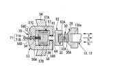
- FIG. 5 is a cross-sectional view showing a schematic configuration of a damping mechanism according to a second modification of the first embodiment.
- the same components as those in the structure shown in FIG. 5
- a damping mechanism 75 according to a second modification of the first embodiment will be described with reference to FIG.
- the damping mechanism 75 has an end on the second magnet 33 side of the cylinder 56 constituting the first damping mechanism 31 described in the first embodiment as an open end, and a damping unit 76 instead of the damping unit 53.
- the configuration is the same as that of the first damping mechanism 31 except for the above.
- the attenuation unit 76 is an eddy current damper.
- the attenuating portion 76 is replaced with the cylinder 56, the piston 57, and the seal members 58 and 64, except that the attenuating portion 76 includes a support plate 81, a metal plate 82, and a magnet 83, as described in the first embodiment.
- the configuration is the same as 53.
- the support plate 81 is disposed in the cylinder 56 so that the outer peripheral surface is in contact with the inner peripheral surface of the cylinder 56.
- the support plate 81 has first and second surfaces 81a and 81b orthogonal to the X direction.
- the first surface 81a is disposed on the push-back portion 54 side.
- the second surface 81b is disposed on the opposite side of the first surface 81a.
- the other end of the push-back portion 54 is connected to the first surface 81 a side of the support plate 81.
- the metal plate 82 is made of a metal material having a high electric conductivity.
- the metal plate 82 is disposed in the cylinder 56.
- the metal plate 82 has first and second surfaces 82a and 82b orthogonal to the X direction.
- the first surface 82 a faces the second surface 81 b of the support plate 81.
- the second surface 82b is disposed on the opposite side of the first surface 82a.
- the metal plate 82 is provided on the support plate 81 so that the first surface 82a is in contact with the second surface 81b.
- the outer peripheral surface of the metal plate 82 is in contact with the inner peripheral surface of the cylinder 56.
- Cu, Au, or the like can be used as a metal material having a high electrical conductivity constituting the metal plate 82.
- the magnet 83 has a plate shape.
- the magnet 83 is disposed in the cylinder 56 so that the outer peripheral surface is in contact with the inner peripheral surface of the cylinder 56.
- the magnet 83 has first and second surfaces 83a and 83b orthogonal to the X direction.
- the first surface 83 a faces the second surface 82 b of the metal plate 82.
- the second surface 83b is disposed on the opposite side of the first surface 83a.
- the second surface 83 b side of the magnet 83 is connected to the rod 61.
- the magnet 83 is provided on the metal plate 82 so that the first surface 83a is in contact with the second surface 82b.
- the outer peripheral surface of the magnet 83 is in contact with the inner peripheral surface of the cylinder 56.
- a permanent magnet can be used as the magnet 83.
- the above-described support plate 81, metal plate 82, and magnet 83 are configured to be movable in the X direction.
- the first and second damping mechanisms 31 and 32 described in the first embodiment have the eddy current damper as the damping portion 76. The same effect can be obtained.
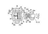
- FIG. 6 is a cross-sectional view illustrating a schematic configuration of a damping mechanism according to a third modification of the first embodiment.
- FIG. 6 the same components as those in the structure shown in FIG. 6, the same components as those in the structure shown in FIG.
- a damping mechanism 85 according to a third modification of the first embodiment will be described with reference to FIG.
- the attenuation mechanism 85 is configured in the same manner as the attenuation mechanism 75 except that it includes an attenuation section 86 instead of the attenuation section 76 that configures the attenuation mechanism 75 of the second modification of the first embodiment.
- the attenuating portion 86 has the same configuration as that of the attenuating portion 76 except that it has a frictional resistance imparting member 89 instead of the structure made up of the support plate 81, the metal plate 82, and the magnet 83.
- the frictional resistance imparting member 89 is provided in the cylinder 56.
- the frictional resistance applying member 89 has an outer peripheral surface in contact with the inner peripheral surface of the cylinder 56.
- the frictional resistance imparting member 89 is configured to be movable in the X direction. When the frictional resistance applying member 89 moves in the X direction, a frictional force is generated between the frictional resistance applying member 89 and the cylinder 56. By this frictional force. The vibration in the X direction of the rotating shaft 12 is suppressed.
- examples of the material of the friction resistance imparting member 89 include a metal or ceramic having excellent wear resistance, and a resin friction material on the surface of the piston. It is possible to construct it.
- the damping portion 86 includes the frictional resistance imparting member 89, so that the vibration of the rotary shaft 12 in the X direction can be attenuated with a simple configuration. Can do.
- FIG. 7 is a cross-sectional view showing a schematic configuration of a damping mechanism according to a fourth modification of the first embodiment.
- the same components as those in the structure shown in FIG. 7
- a damping mechanism 95 according to a fourth modification of the first embodiment will be described with reference to FIG.
- the attenuation mechanism 95 is configured in the same manner as the attenuation mechanism 75 except that it includes an attenuation unit 96 instead of the attenuation unit 76 that configures the attenuation mechanism 75 of the second modification of the first embodiment.
- the attenuating portion 96 has the same configuration as the attenuating portion 76 except that it has a viscoelastic member 98 and a support plate 99 instead of the metal plate 82 and the magnet 83.
- the viscoelastic member 98 is a plate-like member made of a viscoelastic material.
- the viscoelastic member 98 is disposed in the cylinder 56.
- the viscoelastic member 98 is sandwiched between the support plate 81 and the support plate 99 in the X direction.
- the viscoelastic member 98 has first and second surfaces 98a and 98b orthogonal to the X direction.
- the first surface 98 a is in contact with the second surface 81 b of the support plate 81.
- the viscoelastic member 98 has a function of attenuating the vibration in the X direction of the rotational shaft 12 (in the case of the arrangement example of FIG. 7 X 2 direction).
- a viscoelastic material used as the material of the viscoelastic member 98 rubber
- the support plate 99 is disposed in the cylinder 56 with the outer peripheral surface in contact with the inner peripheral surface of the cylinder 56.
- the support plate 99 has first and second surfaces 99a and 99b orthogonal to the X direction.
- the first surface 99 a is in contact with the second surface 98 b of the viscoelastic member 98.
- a rod 61 is connected to the second surface 99 b side of the support plate 99.
- the support plates 81 and 99 and the viscoelastic member 98 are configured to be integrally movable in the X direction.
- the damping unit 96 includes the viscoelastic member 98, so that the vibration of the rotating shaft 113 in the X direction can be damped.
- damping mechanisms 75, 85, and 95 shown in FIGS. 5 to 7 may be provided with the screw hole 56D, the screw 71, and the seal member 72 shown in FIG. In this case, the same effect as that of the damping mechanism 70 shown in FIG. 4 can be obtained.
- the damping mechanisms 70, 75, 85, and 95 shown in FIGS. 4 to 7 may be provided at both ends of the rotary shaft main body 13.
- FIG. 8 is a cross-sectional view showing a schematic configuration of a rotating machine according to the second embodiment of the present invention.
- the same components as those of the structure shown in FIG. 8.
- the rotary machine 110 of the second embodiment excludes the radial bearing 21, the second impeller 27, and the position regulating member 29 that constitute the rotary machine 10 of the first embodiment from the constituent elements. It has been configured.
- the rotating machine 110 changes the positions of the first and second damping mechanisms 31 and 32, the first and second magnets 30 and 33, and the rotation driving unit 15 provided in the rotating machine 10.
- the rotating machine 110 has a casing 111 and a rotating shaft 113 instead of the casing 11 and the rotating shaft 12 constituting the rotating machine 10, and further includes support members 115 and 116, and the rotating machine of the first embodiment.
- the configuration is the same as in FIG.
- the casing 111 has the same configuration as the casing 11 except that the second and third casing portions 38 and 42 are removed from the casing 11 described in the first embodiment.
- the rotary shaft 113 includes the rotary shaft main body 13 and the thrust collar 118 described in the first embodiment.
- the thrust collar 118 is provided in a portion of the rotary shaft main body 13 that is accommodated in the first casing portion 36.
- the thrust collar 118 is a circular plate material whose diameter is larger than the outer diameter of the rotary shaft main body 13.
- the thrust collar 118 has first and second surfaces 118a and 118b orthogonal to the X direction.
- the first surface 118 a faces the first impeller 26.
- the second surface 118b is disposed on the opposite side of the first surface 118a.
- the rotation drive unit 15 is provided outside the casing 111 in a state where the rotation shaft 12 can be rotated.
- the first magnet 30 is provided on the first and second surfaces 118a and 118b of the thrust collar 118 so as to face each other in the X direction with the thrust collar 118 interposed therebetween. Three or more pairs of the first magnets 30 that are arranged to face each other are arranged at a predetermined interval in the circumferential direction of the thrust collar 118.
- the first damping mechanism 31 is provided in the first casing portion 36 so as to face the first magnet 30 provided on the first surface 118a of the thrust collar 118. Three or more first damping mechanisms 31 are arranged in the circumferential direction of the thrust collar 118.
- the second damping mechanism 32 is provided in the first casing portion 36 so as to face the first magnet 30 provided on the second surface 118b of the thrust collar 118.
- the second damping mechanism 32 is disposed opposite to the first damping mechanism 31 across the thrust collar 118 in the X direction.
- Three or more second damping mechanisms 32 are arranged in the circumferential direction of the thrust collar 118.
- the support member 115 has one end connected to the inner wall of the first casing portion 36 and the other end connected to the cylinder 56 constituting the first damping mechanism 31. Thereby, the support member 115 supports the first damping mechanism 31.
- the support member 116 has one end connected to the inner wall of the first casing portion 36 and the other end connected to the cylinder 56 constituting the second damping mechanism 32. Thereby, the support member 116 supports the second damping mechanism 32.
- the structure including the first magnet 30, the second magnet 33, and the damping mechanism (the first damping mechanism 31 or the second damping mechanism 32)
- the thrust collar 118 By arranging the thrust collar 118 on both sides (the first surface 118a side and the second surface 118b side) of the thrust collar 118 so as to sandwich the thrust collar 118 from the direction, the vibration of the rotary shaft 113 in the X direction can be attenuated. it can.
- a structure including the first magnet 30, the second magnet 33, and the first damping mechanism 31, and a structure including the first magnet 30, the second magnet 33, and the second damping mechanism 32. are provided in the circumferential direction of the thrust collar 118, respectively, so that the inclination of the thrust collar 118 with respect to the X direction can be suppressed and the vibration of the rotary shaft 12 in the X direction can be attenuated.
- the rotary machine of the present invention can be applied to a compressor, a turbine, or the like.
Landscapes
- Engineering & Computer Science (AREA)
- General Engineering & Computer Science (AREA)
- Mechanical Engineering (AREA)
- Physics & Mathematics (AREA)
- Acoustics & Sound (AREA)
- Aviation & Aerospace Engineering (AREA)
- Electromagnetism (AREA)
- Structures Of Non-Positive Displacement Pumps (AREA)
- Connection Of Motors, Electrical Generators, Mechanical Devices, And The Like (AREA)
Abstract
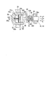
回転軸(12)に設けられた第1の磁石(30)と、ケーシング(11)に支持されるとともに、スラスト方向(X方向)において第1の磁石(30)と対向配置された減衰機構(31,32)と、第1の磁石(30)と対向するように減衰機構(31,32)に設けられ、第1の磁石(30)に対して反発する第2の磁石(33)と、を備え、減衰機構は、スラスト方向における回転軸(12)の振動を減衰させる減衰部、及び減衰部の可動部を回転軸(12)に向かう方向に押し戻す押し戻し部を含む。
Description
本発明は、回転機械に関する。
回転機械のうちの1つである圧縮機は、ケーシング、回転軸、インペラ、ラジアル軸受、及びスラスト軸受を有する。ケーシングは、流体を導入する流体導入口と、インペラにより圧縮された流体を導出する流体導出口と、を有する。回転軸は、ケーシング内に収容されており、ケーシングの長手方向に延在している。
インペラは、回転軸の一方の端に設けられており、回転軸とともに回転する。インペラは、導入された流体を圧縮し、圧縮した流体を流体導出口へと導く。ラジアル軸受は、回転軸の外周面と対向するように配置されている。ラジアル軸受は、回転軸を回転可能に支持している。スラスト軸受は、回転軸の他方の端側に設けられている。スラスト軸受は、回転軸のスラスト方向を支持している。
特許文献1には、回転軸のスラスト方向の変位を抑制することを目的としたスラスト軸受が開示されている。特許文献1に開示されたスラスト軸受は、回転軸の他方の端に配置された第1の永久磁石と、第1の永久磁石からスラスト方向に離間して配置され、第1の永久磁石に対して反発する第2の永久磁石と、で構成されている。
ところで、回転軸にスラスト方向の加振力が働いている状態では、回転軸がスラスト方向に大きく振動してしまう。しかしながら、特許文献1に開示された技術では、スラスト方向への回転軸の振動を減衰させる構成がない。このため、スラスト方向への回転軸の振動を減衰できない可能性があった。
そこで、本発明は、スラスト方向における回転軸の振動を減衰させることの可能な回転機械を提供する。
本発明の第1の態様に係る回転機械は、ケーシングと、前記ケーシング内に回転可能な状態で支持され、スラスト方向に延在する回転軸と、前記回転軸に設けられた第1の磁石と、前記ケーシングに支持されるとともに、前記スラスト方向において前記第1の磁石と対向配置された減衰機構と、前記スラスト方向において前記第1の磁石と対向するように前記減衰機構に設けられ、前記第1の磁石に対して反発する第2の磁石と、を備え、前記減衰機構は、前記スラスト方向における前記第2の磁石の振動を減衰させる減衰部、及び前記第2の磁石を前記第1の磁石に向かう方向に押し戻す押し戻し部を含む。
このように、スラスト方向における第2の磁石の振動を減衰させる減衰部を有することで、回転軸が減衰機構に向かう方向に移動した際に減衰部によりスラスト方向に働く力を小さくすることが可能となる。そして、第2の磁石を第1の磁石に向かう方向に押し戻す力を付与する押し戻し部を有することで、減衰部の可動部の位置を回転軸側に戻して(減衰部が機能する位置に戻して)、スラスト方向に働く力を繰り返し減衰させることが可能となる。したがって、スラスト方向における回転軸の振動を減衰させることができる。
また、回転軸に設けられた第1の磁石と、第1の磁石と対向するように減衰機構に設けられ、第1の磁石に対して反発する第2の磁石と、を有することで、第1の磁石と第2の磁石との間を非接触の状態にてバネで連結したのと同様の機能を有することが可能となる。これにより、スラスト方向に回転軸が振動した場合でも第1の磁石と第2の磁石との衝突を回避することが可能となるので、第1及び第2の磁石の損傷を抑制することができる。
また、本発明の第2の態様に係る回転機械において、前記押し戻し部は、弾性体であってもよい。
このように、押し戻し部として弾性体を用いることで、第2の磁石を第1の磁石に向かう方向に押し戻すことができる。
また、本発明の第3の態様に係る回転機械において、前記減衰部は、粘性流体ダンパであってもよい。
このように、減衰部として粘性流体ダンパを用いることで、スラスト方向における回転軸の振動を減衰させることができる。
また、本発明の第4の態様に係る回転機械において、前記減衰部は、エディカレントダンパであってもよい。
このように、減衰部としてエディカレントダンパを用いることで、スラスト方向における回転軸の振動を減衰させることができる。
また、本発明の第5の態様に係る回転機械において、前記減衰部は、摩擦抵抗付与部材であってもよい。
このように、減衰部として摩擦抵抗付与部材を用いることで、スラスト方向における回転軸の振動を減衰させることができる。
また、本発明の第6の態様に係る回転機械において、前記減衰部は、粘弾性部材であってもよい。
このように、減衰部として粘弾性部材を用いることで、スラスト方向における回転軸の振動を減衰させることができる。
また、本発明の第7の態様に係る回転機械において、前記第1及び第2の磁石のうち、一方が凸部を有し、他方が前記凸部の一部が収容される凹部を有しており、前記凸部及び前記凹部は、前記スラスト方向において対向配置されていてもよい。
このように、第1及び第2の磁石のうち、一方が凸部を有し、他方が凸部の一部が収容される凹部を有するとともに、凸部及び凹部をスラスト方向において対向配置させることで、第1の磁石に対する第2の磁石の径方向の位置(第2の磁石に対する第1の磁石の径方向の位置)を規制することが可能となる。これにより、第1及び第2の磁石を経由して、スラスト方向における回転軸の振動を精度良く減衰機構に伝達させることができる。また、第1の磁石が設けられた回転軸を中心軸上に精度よく保持することができる。
また、本発明の第8の態様に係る回転機械において、前記回転軸の一方の端に設けられたインペラと、前記ケーシングに対して前記減衰機構を支持する複数の支持部と、を備え、前記ケーシングは、前記インペラと対向配置され、前記ケーシング内に流体を導入させる流体導入部を含み、前記減衰機構は、前記流体導入部内に配置されており、前記複数の支持部材により支持されていてもよい。
このように、ケーシングを構成する流体導入部内に減衰機構を配置させることで、回転機械の大型化を抑制した上で、スラスト方向における回転軸の振動を減衰させることができる。
また、本発明の第9の態様に係る回転機械において、前記回転軸は、前記スラスト方向に延在する回転軸本体を含み、前記減衰機構は、前記回転軸本体の一方の端側に設けてもよい。
このように、回転軸本体の一方の端側に減衰機構を設けることで、回転軸本体の延在方向に減衰機構を配置することが可能となる。これにより、回転軸の延在方向からずれた位置に減衰機構を配置させたときよりもスラスト方向における回転軸の振動を精度良く減衰させることができる。
また、本発明の第10の態様に係る回転機械において、前記回転軸は、前記スラスト方向に延在する回転軸本体を含み、前記減衰機構は、前記回転軸本体の両端にそれぞれ設けてもよい。
このように、回転軸本体の両端に減衰機構を設けることで、回転軸本体の延在方向(回転軸が振動する方向)において、回転軸本体を挟み込むように減衰機構が配置される。これにより、2方向(一方の端に設けられた減衰機構に回転軸が近づくスラスト方向、及び他方の端に設けられた減衰機構に回転軸が近づくスラスト方向)に働く力を繰り返し減衰させることが可能となるので、スラスト方向における回転軸の振動の減衰効果を高めることができる。
また、本発明の第11の態様に係る回転機械において、前記回転軸は、前記スラスト方向に延在する回転軸本体と、該回転軸本体に設けられたスラストカラーと、を含み、前記第1の磁石、前記第2の磁石、及び前記減衰機構は、前記スラスト方向から前記スラストカラーを挟み込むように、該スラストカラーの前記スラスト方向の両側にそれぞれ設けてもよい。
このように、スラスト方向からスラストカラーを挟み込むように減衰機構を設けた場合も、スラスト方向における回転軸の振動を減衰させることができる。
また、本発明の第12の態様に係る回転機械において、前記スラストカラーを挟み込む一対の前記減衰機構は、前記スラストカラーの周方向に3つ以上配置させてもよい。
このように、スラストカラーを挟み込む一対の減衰機構をスラストカラーの周方向に3つ以上配置させることで、回転軸本体の延在方向に対してスラストカラーが傾斜することを抑制した上で、スラスト方向における回転軸の振動を減衰させることができる。
また、本発明の第13の態様に係る回転機械において、前記回転軸の一方の端に設けられた第1のインペラと、前記回転軸の他方の端に設けられた第2のインペラと、前記ケーシングに対して前記減衰機構を支持する複数の支持部と、を備え、前記ケーシングは、前記第1のインペラと対向配置され、前記ケーシング内に第1の流体を導入させる第1の流体導入部と、前記第2のインペラと対向配置され、前記ケーシング内に第2の流体を導入させる第2の流体導入部と、を含み、前記減衰機構は、前記第1の流体導入部内と前記第2の流体導入部内とにそれぞれ配置されるとともに、前記複数の支持部材により支持されていてもよい。
このように、ケーシングを構成する第1の流体導入部内に減衰機構を配置させるとともに、第2の流体導入部内に減衰機構を配置させることで、回転機械の大型化を抑制した上で、スラスト方向における回転軸の振動を精度良く減衰させることができる。
本発明によれば、スラスト方向における回転軸の振動を減衰させることができる。
〔第1の実施形態〕
図1は、本発明の第1の実施形態に係る回転機械の概略構成を示す断面図である。図1に示すX1方向は第1の減衰機構31から回転軸本体13に向かう方向、X2方向は第2の減衰機構32から回転軸本体13に向かう方向、X方向はX1方向及びX2方向を含むスラスト方向(回転軸本体13の延在方向)、O1はX方向に延在する回転軸12の軸線(以下、「軸線O1」という)をそれぞれ示している。
図1は、本発明の第1の実施形態に係る回転機械の概略構成を示す断面図である。図1に示すX1方向は第1の減衰機構31から回転軸本体13に向かう方向、X2方向は第2の減衰機構32から回転軸本体13に向かう方向、X方向はX1方向及びX2方向を含むスラスト方向(回転軸本体13の延在方向)、O1はX方向に延在する回転軸12の軸線(以下、「軸線O1」という)をそれぞれ示している。
図2は、図1に示す回転機械を模式的に示す断面図である。図2において、図1に示す構造体と同一構成部分には同一符号を付す。図3は、図1に示す回転機械のうち、領域Aで囲んだ部分を拡大した断面図である。図3では、図1及び図2に示す構造体と同一構成部分には同一符号を付す。
図1~図3を参照するに、第1の実施形態の回転機械10は、ケーシング11と、回転軸12と、回転駆動部15と、軸受支持部材16,17と、ラジアル軸受19,21と、シール部材23,24と、第1のインペラ26と、第2のインペラ27と、位置規制部材28,29と、2つの第1の磁石30と、第1の減衰機構31と、第2の減衰機構32と、2つの第2の磁石33と、複数の支持部材34,35と、を有する。
ケーシング11は、第1のケーシング部36と、第2のケーシング部37,38と、第3のケーシング部41,42と、流路43,44と、を有する。
第1のケーシング部36は、両端が開放端とされた筒状の部材である。第1のケーシング部36は、X方向に延在している。第1のケーシング部36の一方の端には、第1のフランジ部36Aが設けられている。第1のケーシング部36の他方の端には、第2のフランジ部36Bが設けられている。
第2のケーシング部37は、第1のフランジ部36Aに固定されている。第2のケーシング部37の中央部には、回転軸本体13の一方の端部13Aの一部が挿入される開口部37Aが設けられている。第2のケーシング部38は、第2のフランジ部36Bに固定されている。第2のケーシング部38の中央部には、回転軸本体13の他方の端部13Bの一部が挿入される開口部38Aが設けられている。
第3のケーシング部41は、第1の流体導入部45と、支持部46と、を有する。第1の流体導入部45は、筒状とされた部材であり、X方向に延在している。第1の流体導入部45は、その内側に円柱形状とされた空間45Aを有する。空間45Aは、第1の流体(例えば、外気)をケーシング11内に配置された第1のインペラ26内に導入するための導入口として機能する。第3のケーシング部41は、回転軸本体13の一方の端部13Aを第1の流体導入部45が収容可能な位置に設けられている。
支持部46は、第1の流体導入部45の他端に設けられている。支持部46の形状は、第1の流体導入部45の外側に広がるような形状とされている。支持部46の一部は、第2のケーシング部37と接触している。支持部46は、ボルト等により第2のケーシング部37に固定されている。
第3のケーシング部42は、第2の流体導入部48と、支持部49と、を有する。第2の流体導入部48は、筒状とされた部材であり、X方向に延在している。第2の流体導入部48は、その内側に円柱形状とされた空間48Aを有する。空間48Aは、第2の流体をケーシング11内に配置された第2のインペラ27内に導入するための導入口として機能する。第2の流体としては、例えば、第1のインペラ26を通過した第1の流体を用いることが可能である。第3のケーシング部42は、回転軸本体13の他方の端部13Bを第2の流体導入部48が収容可能な位置に設けられている。
支持部49は、第2の流体導入部48の他端に設けられている。支持部49の形状は、第2の流体導入部48の外側に広がるような形状とされている。支持部49の一部は、第2のケーシング部38と接触している。支持部49は、ボルト等により第2のケーシング部38に固定されている。
流路43は、第2のケーシング部37と第3のケーシング部41との間に形成されている。流路43には、第1のインペラ26から導出された第1の流体が流れる。流路44は、第2のケーシング部38と第3のケーシング部42との間に形成されている。流路44には、第2のインペラ27から導出された第2の流体が流れる。
回転軸12は、回転軸本体13を含む。回転軸本体13は、X方向に延在した状態でケーシング11内に収容されている。回転軸本体13の形状は、例えば、円柱形状とすることが可能である。回転軸本体13は、ラジアル軸受19,21により回転可能な状態で支持されている。回転軸本体13は、一方の端部13Aと、他方の端部13Bと、を有する。
一方の端部13Aは、一方の端13Aaを含む。一方の端部13Aのうち、一方の端13Aaを含む一部は、第1の流体導入部45から離間した状態で第1の流体導入部45内に収容されている。一方の端部13Aは、第1のインペラ26が挿入される部分である。一方の端部13Aは、他方の端部13Bを除く回転軸本体13の他の部分よりも縮径されている。これにより、第1のインペラ26のX1方向の位置を規制することが可能となる。
他方の端部13Bは、一方の端部13Aの反対側に設けられた端部であり、他方の端13Baを含む。他方の端部13Bのうち、他方の端13Baを含む一部は、第2の流体導入部48から離間した状態で第2の流体導入部48内に収容されている。他方の端部13Bは、第2のインペラ27が挿入される部分である。他方の端部13Bは、一方の端部13Aを除く回転軸本体13の他の部分よりも縮径されている。これにより、第2のインペラ27のX2方向の位置を規制することが可能となる。
回転駆動部15は、ロータ51と、ステータ52と、を有する。ロータ51は、回転軸本体13の中央部の外周面13aに固定されている。ステータ52は、ロータ51と対向する第1のケーシング部36の内周面36aに設けられている。回転駆動部15は、ロータ51を回転させることで、ロータ51とともに回転軸本体13を回転させる。
軸受支持部材16,17は、リング状の部材であり、第1のケーシング部36内に収容されている。軸受支持部材16,17は、第1のケーシング部36の内側に固定されている。軸受支持部材16,17は、X方向において回転駆動部15を挟んで対向するように配置されている。軸受支持部材16,17の内周面16a,17aは、ラジアル軸受19,21を配置可能な隙間を介在させた状態で、回転軸本体13の外周面13aと対向している。
ラジアル軸受19は、軸受支持部材16の内周面16aに設けられている。ラジアル軸受21は、軸受支持部材17の内周面17aに設けられている。ラジアル軸受19,21としては、例えば、ジャーナル軸受を用いることが可能である。
シール部材23は、第2のケーシング部37のうち、開口部37Aを区画する部分に設けられている。シール部材24は、第2のケーシング部38のうち、開口部38Aを区画する部分に設けられている。シール部材23,24は、回転軸本体13と第2のケーシング部37,38との間をシールしている。
第1のインペラ26は、ディスク部26Aと、カバー部26Bと、複数のブレード部26Cと、流路26Dと、を有する。ディスク部26Aは、中央に貫通穴26Aaが形成されている。複数のブレード部26Cは、ディスク部26Aに立設されており、ディスク部26Aとカバー部26Bとの間に配置されている。
流路26Dは、ディスク部26A、カバー部26B、及びブレード部26Cにより区画されている。流路26Dは、空間45A及び流路43と接続されている。流路26Dには、第1の流体が導入され、圧縮された第1の流体が流路43に導出される。
上記構成とされた第1のインペラ26は、貫通穴26Aaに回転軸本体13の一方の端部13Aの一部が挿入された状態で、回転軸本体13の一方の端部13Aに設けられている。これにより、第1のインペラ26は、回転軸本体13が回転した際に回転する。第1のインペラ26は、一方の端13Aaを露出している。
第2のインペラ27は、先に説明した第1のインペラ26と同様な構成とされている。つまり、第2のインペラ27は、ディスク部26Aと、カバー部26Bと、複数のブレード部26Cと、流路26Dと、を有する。第2のインペラ27は、貫通穴26Aaに回転軸本体13の他方の端部13Bの一部が挿入された状態で、回転軸本体13の他方の端部13Bに設けられている。
第2のインペラ27を構成する流路26Dは、空間48A及び流路44と接続されている。第2のインペラ27を構成する流路26Dには、第2の流体が導入され、圧縮された第2の流体が流路44に導出される。第2のインペラ27は、他方の端13Baを露出している。
位置規制部材28は、回転軸本体13の一方の端13Aaに設けられている。位置規制部材28は、第1のインペラ26のX2方向への移動を規制する部材である。位置規制部材29は、回転軸本体13の他方の端13Baに設けられている。位置規制部材29は、第2のインペラ27のX1方向への移動を規制する部材である。
2つの第1の磁石30のうち、一方の第1の磁石30は、位置規制部材28に設けられている。一方の第1の磁石30は、X方向において位置規制部材28の一部を挟んで回転軸本体13の一方の端13Aaと対向するように配置されている。
他方の第1の磁石30は、X方向において位置規制部材29の一部を挟んで回転軸本体13の他方の端13Baと対向するように配置されている。第1の磁石30は、第2の磁石33と対向する部分に凹部30Aを有する。第1の磁石30としては、例えば、永久磁石を用いることが可能である。
第1の減衰機構31は、第1の流体導入部45の内面との間に第1の流体を導入可能な流路を形成可能な状態で、空間45Aに配置されている。第1の減衰機構31は、減衰部53と、押し戻し部54と、を有する。減衰部53は、粘性流体ダンパであり、シリンダ56と、ピストン57と、シール部材58,64と、ロッド61と、磁石支持部62と、を有する。
シリンダ56は、第1の流体導入部45と接触しない状態で、第1の流体導入部45内に配置されている。シリンダ56は、複数の支持部材34と接続されている。シリンダ56は、複数の支持部材34を介して、第1の流体導入部45に支持されている。シリンダ56は、空間56Aと、開口部56Bと、凹部56Cと、を有する。空間56Aは、シリンダ56の内部に形成されている。空間56Aは、円柱形状とされており、X方向に延在している。
開口部56Bは、シリンダ56のうち、第1の磁石30と対向する部分を貫通するように設けられている。シリンダ56内には、粘性流体が充填された状態で、ロッド61の一部、シール部材58、ピストン57、及び押し戻し部54の一部が配置されている。粘性流体としては、例えば、オイル、磁性流体、シリコンゲル等を用いることが可能である。
凹部56Cは、ピストン57のうち、ロッド61が接続される面とは反対側に位置する面と対向する部分に設けられている。凹部56Cは、回転軸本体13の一方の端13Aaの延長上に配置されている。凹部56Cには、押し戻し部54の一部が収容されている。
ピストン57は、ピストン本体57Aと、複数の貫通穴57Bと、凹部57Cと、を有する。ピストン本体57Aは、X方向に移動可能な状態で、シリンダ56内の空間56Aに配置されている。複数の貫通穴57Bは、ピストン本体57Aのうち、ピストン本体57Aとロッド61との接続位置よりも外側に位置する部分に設けられている。複数の貫通穴57Bは、粘性流体が移動可能な穴であり、ピストン本体57AをX方向に貫通している。
ピストン57がX方向(図3の配置例の場合、X2方向)に押されると、複数の貫通穴57Bを粘性流体が移動することで抵抗が発生し、X方向における第2の磁石33の振動が減衰される。このように、X方向における第2の磁石33の振動が減衰されることで、X方向における回転軸12の振動が減衰される。
凹部57Cは、ピストン本体57Aのうち、ロッド61が接続される側とは反対側に位置する部分に設けられている。凹部57Cは、X方向において凹部56Cと対向するように配置されている。凹部57Cは、押し戻し部54の一部が収容される。凹部57Cは、X方向においてピストン本体57Aの一部を挟んで、ロッド61と対向するように配置されている。
このように、X方向においてピストン本体57Aの一部を挟んで、ロッド61と対向するように、押し戻し部54の一部が収容される凹部57Cを設けることで、X方向に対するピストン57の傾斜を抑制した上で、押し戻し部54によりピストン57をX1方向に押し戻すことができる。
シール部材58は、シリンダ56の内周面とピストン本体57Aの外周面との間に設けられている。
ロッド61は、X方向に延在しており、開口部56Bに挿入されている。ロッド61は、一端がピストン本体57Aと接続されており、他端が磁石支持部62と接続されている。
磁石支持部62は、第1の磁石30と対向する部分に第2の磁石33を収容する収容部62Aを有する。磁石支持部62は、ピストン57及びロッド61とともにX方向に移動する。
シール部材64は、開口部56Bを区画するシリンダ56とロッド61の外周面との間に設けられている。
押し戻し部54は、シリンダ56内に設けられている。押し戻し部54の一方の端部は、凹部56C内に収容された状態で、凹部56Cを区画するシリンダ56に固定されている。押し戻し部54の他方の端部は、凹部57C内に収容された状態で、凹部57Cを区画するピストン57に固定されている。
このように、X方向において対向配置された凹部56C,57C内に押し戻し部54の一部を配置させることで、押し戻し部54の変位方向がX方向となるように案内することができる。
押し戻し部54は、X方向に延在するとともに、X方向に移動可能な構成とされている。押し戻し部54は、ピストン57がX2方向(図3の場合)に移動させられた際、第2の磁石33をX1方向(第1の磁石30に向かう方向)に押し戻す。これにより、押し戻し部54は、減衰部の可動部であるピストン57をX1方向(回転軸に向かう方向)に押し戻す。
このように、X2方向に移動させられた第2の磁石33を押し戻し部54がX1方向に押し戻すことで、減衰部53により回転軸本体13のX方向の振動を繰り返し減衰させることができる。
押し戻し部54としては、例えば、弾性体(例えば、ばね)を用いることが可能であるが、これに替えて、互いに反発する向きで配置された一対の磁石を用いてもよい。
なお、図1~図3では、押し戻し部54の一例として、弾性体であるばねを図示したが、この場合、ばねのばね定数と第1の磁石30と第2の磁石33との反発力とが等しくなるように設定するとよい。
上記構成とされた第1の減衰機構31は、例えば、その中心軸が回転軸12の軸線O1と一致するように配置させるとよい。このような位置に第1の減衰機構31を配置させることで、第1の流体を第1のインペラ26に導く際に第1の減衰機構31が障害になることを抑制できる。
上記構成とされた第1の減衰機構31によれば、回転軸本体13がX2方向(第1の減衰機構31に向かう方向)に移動した際に減衰部53によりX方向に働く力を小さくすることが可能となる。そして、減衰部53の可動部であるピストン57をX1方向(回転軸本体13に向かう方向)に押し戻す力を付与する押し戻し部54を有することで、減衰部53のピストン57の位置を回転軸本体13側に戻して(減衰部53が機能する位置に戻して)、X方向に働く力を繰り返し減衰させることが可能となる。したがって、X方向における回転軸本体13の振動を減衰させることができる。
第2の減衰機構32は、第2の流体導入部48内の空間48Aに配置されていること以外は、先に説明した第1の減衰機構31と同様な構成とされている。
第1及び第2の減衰機構31,32は、回転軸本体13の両端(一方の端13Aa、及び他方の端13Ba)に配置されている。
第1及び第2の減衰機構31,32は、回転軸本体13の両端(一方の端13Aa、及び他方の端13Ba)に配置されている。
このように、回転軸本体13の両端に第1及び第2の減衰機構31,32を設けることで、回転軸本体13の延在方向に、回転軸本体13を挟み込むように第1及び第2の減衰機構31,32を配置することが可能となる。これにより、X1方向及びX2方向(第1の減衰機構31に第2の減衰機構32に近づく方向、及び第2の減衰機構32に第1の減衰機構31に近づく方向)に働く力を繰り返し減衰させることが可能となるので、X方向における回転軸12の振動の減衰効果を高めることができる。
また、回転軸本体13の両端に第1及び第2の減衰機構31,32を設けることで、回転軸の延在方向(軸線O1方向)からずれた位置に第1及び第2の減衰機構31,32を配置させた場合と比較して、X方向における回転軸12の振動を精度良く減衰させることができる。
2つの第2の磁石33のうち、一方の第2の磁石33は、第1の磁石30に対して反発する向きで、第1の減衰機構31を構成する磁石支持部62の収容部62A内に設けられている。他方の第2の磁石33は、第1の磁石30に対して反発する向きで第2の減衰機構32を構成する磁石支持部62の収容部62A内に設けられている。第1及び第2の磁石30,33は、X方向で対向するように配置されている。第1及び第2の磁石30,33の対向する部分は、同極(S極同士、またはN極同士)とされている。
このような構成とすることで、第1の磁石30と第2の磁石33と間に僅かな隙間が形成されるため、第1の磁石30と第2の磁石33との間を非接触状態にてバネで連結したのと同様の機能を有することが可能となる。これにより、X方向に回転軸12が振動した場合でも第1の磁石30と第2の磁石33との衝突を抑制可能となるので、第1及び第2の磁石30,33の損傷を抑制できる。
第2の磁石33は、X方向において第1の磁石30に設けられた凹部30Aと対向する凸部33Aを有する。凸部33Aの形状は、その一部が凹部30A内に配置可能な形状とされている。凸部33Aは、その一部が凹部30A内に配置されている。
このように、第1の磁石30に凹部30Aを設けるとともに、凹部30Aに一部が収容される凸部33Aを第2の磁石33に設けることで、第1の磁石30に対する第2の磁石33の径方向の位置(第2の磁石33に対する第1の磁石30の径方向の位置)を規制することが可能となる。これにより、X方向における回転軸12の振動を精度良く第1及び第2の減衰機構31,32に伝達させることができる。また、第1の磁石が設けられた回転軸を中心軸上に精度よく保持することができる。
第2の磁石33としては、例えば、永久磁石または電磁石を用いることが可能である。
なお、図1~図3では、一例として、第1の磁石30に凹部30Aを設け、第2の磁石33に凸部33Aを設けた場合を例に挙げて説明したが、例えば、第1の磁石30に凸部を設け、第2の磁石33に凹部を設けてもよい。また、凹部30A及び凸部33Aは、必要に応じて設ければよく、必須の構成ではない。
複数の支持部材34は、第1の流体導入部45内に設けられている。複数の支持部材34は、一端が第1の流体導入部45の内壁に接続されており、他端が第1の減衰機構31を構成するシリンダ56と接続されている。複数の支持部材34は、シリンダ56の周方向に配置されている。複数の支持部材34の形状は、例えば、翼形状にするとよい。このように、複数の支持部材34の形状を翼形状とすることで、複数の支持部材34が第1の流体の導入の妨げになることを抑制できる。
複数の支持部材35は、第2の流体導入部48内に設けられている。複数の支持部材35は、一端が第2の流体導入部48の内壁に接続されており、他端が第2の減衰機構32を構成するシリンダ56と接続されている。複数の支持部材35は、シリンダ56の周方向に配置されている。複数の支持部材35の形状は、例えば、翼形状にするとよい。このように、複数の支持部材35の形状を翼形状とすることで、複数の支持部材35が第2の流体の導入の妨げになることを抑制できる。
第1の実施形態の回転機械10によれば、回転軸本体13の両端(一方の端13Aa、及び他方の端13Ba)に対向配置された第1及び第2の磁石30,33を設けるとともに、第2の磁石33を支持する第1及び第2の減衰機構31,32を設けることで、回転軸12がX方向に移動した際に第1及び第2の減衰機構31,32を構成する減衰部53によりX方向に働く力を小さくすることが可能となる。
そして、第1及び第2の減衰機構31,32を構成する押し戻し部54により、減衰部53のピストン57の位置を回転軸12側に戻して(減衰部53が機能する位置に戻して)、X方向に働く力を繰り返し減衰させることが可能となる。したがって、X方向における回転軸12の振動を減衰させることができる。
また、互いに反発する向きで配置された第1及び第2の磁石30,33を有することで、第1の磁石30と第2の磁石33との間を非接触状態とし、かつバネで連結したのと同様の機能を有することが可能となる。これにより、X方向に回転軸12が振動した場合でも第1の磁石30と第2の磁石33との接触を抑制することが可能となるので、第1及び第2の磁石30,33の損傷を抑制できる。
なお、第1の実施形態では、一例として、回転軸本体13の両端に第1の及び第2の減衰機構31,32を設けた場合を例に挙げて説明したが、例えば、回転軸本体13の両端の一方に減衰機構(第1の減衰機構31または第2の減衰機構32)を設けてもよい。この場合、回転軸本体13の両端の他方に減衰機構に向かう方向(X1方向またはX2方向)に対して常に力を印加する外力付与機構を設けるとよい。このような構成とされた回転機械は、第1の実施形態の回転機械10と同様な効果を得ることができる。
図4は、第1の実施形態の第1変形例に係る減衰機構の概略構成を示す断面図である。図4において、図3に示す構造体と同一構成部分には同一符号を付す。
図4を参照して、第1の実施形態の第1変形例に係る減衰機構70について説明する。減衰機構70は、第1の実施形態で説明した第1の減衰機構31の構成に、ねじ穴56D、ねじ71、及びシール部材72を有すること以外は、第1の減衰機構31と同様な構成とされている。
ねじ穴56Dは、シリンダ56のうち、X方向において凹部56Cと対向する部分を貫通するように設けられている。ねじ穴56Dは、X方向に延在しており、凹部56Cに到達している。ねじ穴56Dは、押し戻し部54の一端を露出されている。
ねじ71は、頭部71Aと、頭部71Aの一端に設けられた軸部71Bと、を有する。ねじ71は、シリンダ56の外側からねじ穴56Dに対して螺合されている。軸部71Bの他端は、押し戻し部54の一端に当接されている。ねじ71がX1方向に移動するようにねじ71を回すと押し戻し部54は縮み、ねじ71がX2方向に移動するようにねじ71を回すと押し戻し部54は伸びる。シール部材72は、ねじ穴56Dを区画するシリンダ56と軸部71Bの外周面との間に設けられている。
第1の実施形態の第1変形例に係る減衰機構70によれば、ねじ穴56D、ねじ71、及びシール部材72を有することで、押し戻し部54としてばねを用いる場合において、X方向(図4の配置例の場合、X2方向)における軸部71Bの他端の位置を調節することが可能となる。これにより、X方向におけるばねの剛性を調節することができる。
図5は、第1の実施形態の第2変形例に係る減衰機構の概略構成を示す断面図である。図5において、図3に示す構造体と同一構成部分には同一符号を付す。
図5を参照して、第1の実施形態の第2変形例に係る減衰機構75について説明する。減衰機構75は、第1の実施形態で説明した第1の減衰機構31を構成するシリンダ56の第2の磁石33側の端部を開放端にするとともに、減衰部53に替えて減衰部76を有すること以外は、第1の減衰機構31と同様な構成とされている。
減衰部76は、エディカレントダンパである。減衰部76は、シリンダ56、ピストン57、及びシール部材58,64に替えて、支持板81、金属板82と、磁石83と、を有すること以外は、第1の実施形態で説明した減衰部53と同様に構成されている。
支持板81は、外周面がシリンダ56の内周面と接触するように、シリンダ56内に配置されている。支持板81は、X方向に対して直交する第1及び第2の面81a,81bを有する。第1の面81aは、押し戻し部54側に配置されている。第2の面81bは、第1の面81aの反対側に配置されている。支持板81の第1の面81a側には、押し戻し部54の他端が接続されている。
金属板82は、高い電気伝導率を有する金属材料で構成されている。金属板82は、シリンダ56内に配置されている。金属板82は、X方向に対して直交する第1及び第2の面82a,82bを有する。第1の面82aは、支持板81の第2の面81bと対向している。第2の面82bは、第1の面82aの反対側に配置されている。金属板82は、第1の面82aが第2の面81bと接触するように支持板81に設けられている。金属板82の外周面は、シリンダ56の内周面と接触している。金属板82を構成する高電気伝導率の金属材料としては、例えば、CuやAu等を用いることが可能である。
磁石83は、板状とされている。磁石83は、外周面がシリンダ56の内周面と接触するように、シリンダ56内に配置されている。磁石83は、X方向に対して直交する第1及び第2の面83a,83bを有する。第1の面83aは、金属板82の第2の面82bと対向している。第2の面83bは、第1の面83aの反対側に配置されている。磁石83の第2の面83b側は、ロッド61と接続されている。
磁石83は、第1の面83aが第2の面82bと接触するように金属板82に設けられている。磁石83の外周面は、シリンダ56の内周面と接触している。磁石83としては、例えば、永久磁石を用いることが可能である。
上述した支持板81、金属板82、及び磁石83は、X方向に移動可能な構成とされている。
第1の実施形態の第2変形例に係る減衰機構75によれば、減衰部76としてエディカレントダンパを有することで、第1の実施形態で説明した第1及び第2の減衰機構31,32と同様な効果を得ることができる。
図6は、第1の実施形態の第3変形例に係る減衰機構の概略構成を示す断面図である。図6において、図5に示す構造体と同一構成部分には同一符号を付す。
図6を参照して、第1の実施形態の第3変形例に係る減衰機構85について説明する。減衰機構85は、第1の実施形態の第2変形例の減衰機構75を構成する減衰部76に替えて、減衰部86を有すること以外は、減衰機構75と同様に構成されている。
減衰部86は、支持板81、金属板82、及び磁石83よりなる構造体に替えて、摩擦抵抗付与部材89を有すること以外は、減衰部76と同様な構成とされている。
摩擦抵抗付与部材89は、シリンダ56内に設けられている。摩擦抵抗付与部材89は、外周面がシリンダ56の内周面と接触している。摩擦抵抗付与部材89は、X方向に移動可能な構成とされている。摩擦抵抗付与部材89がX方向に移動すると、シリンダ56との間において摩擦力が発生する。この摩擦力により。回転軸12のX方向の振動を抑制する。
シリンダ56の材料が耐摩耗性に優れた金属材料である場合、摩擦抵抗付与部材89の材料としては、例えば、耐摩耗性に優れた金属やセラミック、金属の表面に樹脂系摩擦材をピストン表面に施工するこが可能である。
第1の実施形態の第3変形例に係る減衰機構85によれば、減衰部86が摩擦抵抗付与部材89を含むことで、簡便な構成で、X方向における回転軸12の振動を減衰させることができる。
図7は、第1の実施形態の第4変形例に係る減衰機構の概略構成を示す断面図である。図7において、図5に示す構造体と同一構成部分には同一符号を付す。
図7を参照して、第1の実施形態の第4変形例に係る減衰機構95について説明する。減衰機構95は、第1の実施形態の第2変形例の減衰機構75を構成する減衰部76に替えて、減衰部96を有すること以外は、減衰機構75と同様に構成されている。
減衰部96は、金属板82及び磁石83に替えて、粘弾性部材98及び支持板99を有すること以外は、減衰部76と同様な構成とされている。
粘弾性部材98は、粘弾性材料で構成された板状の部材である。粘弾性部材98は、シリンダ56内に配置されている。粘弾性部材98は、X方向において支持板81と支持板99との間に挟まれている。粘弾性部材98は、X方向に対して直交する第1及び第2の面98a,98bを有する。第1の面98aは、支持板81の第2の面81bと接触している。粘弾性部材98は、回転軸12のX方向(図7の配置例の場合X2方向)の振動を減衰させる機能を有する。粘弾性部材98の材料となる粘弾性材料としては、例えば、ゴムを例示することが可能である。
支持板99は、外周面がシリンダ56の内周面と接触した状態で、シリンダ56内に配置されている。支持板99は、X方向に対して直交する第1及び第2の面99a,99bを有する。第1の面99aは、粘弾性部材98の第2の面98bと接触している。支持板99の第2の面99b側には、ロッド61が接続されている。
支持板81,99及び粘弾性部材98は、一体的にX方向に移動可能な構成とされている。
第1の実施形態の第4変形例に係る減衰機構95によれば、減衰部96が粘弾性部材98を含むことで、X方向における回転軸113の振動を減衰させることができる。
なお、図5~図7に示す減衰機構75,85,95に、図4に示すねじ穴56D、ねじ71、及びシール部材72を設けてもよい。この場合、図4に示す減衰機構70と同様な効果を得ることができる。また、図4~図7に示す減衰機構70,75,85,95は、回転軸本体13の両端に設けてもよい。
〔第2の実施形態〕
図8は、本発明の第2の実施形態に係る回転機械の概略構成を示す断面図である。図8において、図2に示す構造体と同一構成部分には同一符号を付す。
図8は、本発明の第2の実施形態に係る回転機械の概略構成を示す断面図である。図8において、図2に示す構造体と同一構成部分には同一符号を付す。
図8を参照するに、第2の実施形態の回転機械110は、第1の実施形態の回転機械10を構成するラジアル軸受21、第2のインペラ27、及び位置規制部材29を構成要素から除いた構成とされている。回転機械110は、回転機械10に設けられた第1及び第2の減衰機構31,32、第1及び第2の磁石30,33、及び回転駆動部15の位置を変更している。
回転機械110は、回転機械10を構成するケーシング11及び回転軸12に替えてケーシング111及び回転軸113を有するとともに、さらに支持部材115,116を有すること以外は、第1の実施形態の回転機械10と同様な構成とされている。
ケーシング111は、第1の実施形態で説明したケーシング11から第2及び第3のケーシング部38,42を除いたこと以外は、ケーシング11と同様な構成とされている。
回転軸113は、第1の実施形態で説明した回転軸本体13と、スラストカラー118と、を有する。スラストカラー118は、回転軸本体13のうち、第1のケーシング部36内に収容された部分に設けられている。スラストカラー118は、回転軸本体13の外径よりも拡径された円形状の板材である。
スラストカラー118は、X方向に対して直交する第1及び第2の面118a,118bを有する。第1の面118aは、第1のインペラ26と対向している。第2の面118bは、第1の面118aの反対側に配置されている。
回転駆動部15は、回転軸12を回転させることが可能な状態で、ケーシング111の外側に設けられている。
第1の磁石30は、スラストカラー118を挟んで、X方向において対向するように、スラストカラー118の第1及び第2の面118a,118bに設けられている。対向配置された一対の第1の磁石30は、スラストカラー118の周方向に所定の間隔を空けた状態で3つ以上配置されている。
第1の減衰機構31は、スラストカラー118の第1の面118a設けられた第1の磁石30と対向するように、第1のケーシング部36内に設けられている。第1の減衰機構31は、スラストカラー118の周方向に3つ以上配置されている。
第2の減衰機構32は、スラストカラー118の第2の面118b設けられた第1の磁石30と対向するように、第1のケーシング部36内に設けられている。
第2の減衰機構32は、X方向においてスラストカラー118を挟んで第1の減衰機構31と対向配置されている。第2の減衰機構32は、スラストカラー118の周方向に3つ以上配置されている。
第2の減衰機構32は、X方向においてスラストカラー118を挟んで第1の減衰機構31と対向配置されている。第2の減衰機構32は、スラストカラー118の周方向に3つ以上配置されている。
支持部材115は、一端が第1のケーシング部36の内壁と接続されており、他端が第1の減衰機構31を構成するシリンダ56と接続されている。これにより、支持部材115は、第1の減衰機構31を支持している。
支持部材116は、一端が第1のケーシング部36の内壁と接続されており、他端が第2の減衰機構32を構成するシリンダ56と接続されている。これにより、支持部材116は、第2の減衰機構32を支持している。
第2の実施形態の回転機械110によれば、第1の磁石30、第2の磁石33、及び減衰機構(第1の減衰機構31または第2の減衰機構32)を含む構造体を、X方向からスラストカラー118を挟み込むように、スラストカラー118の両側(第1の面118a側及び第2の面118b側)にそれぞれ配置させることで、X方向における回転軸113の振動を減衰させることができる。
また、第1の磁石30、第2の磁石33、及び第1の減衰機構31を含む構造体と、第1の磁石30、第2の磁石33、及び第2の減衰機構32を含む構造体と、をそれぞれスラストカラー118の周方向にそれぞれ3つ以上設けることで、X方向に対するスラストカラー118の傾斜を抑制した上で、X方向における回転軸12の振動を減衰させることができる。
本発明の回転機械は、圧縮機やタービン等に適用可能である。
10,110 回転機械
11,111 ケーシング
12,113 回転軸
13 回転軸本体
13a 外周面
13A 一方の端部
13Aa 一方の端
13B 他方の端部
13Ba 他方の端
15 回転駆動部
16,17 軸受支持部材
16a,17a,36a 内周面
19,21 ラジアル軸受
23,24,58,64,72 シール部材
26 第1のインペラ
26A ディスク
26Aa、57B 貫通穴
26B カバー部
26C ブレード部
26D,43,44 流路
27 第2のインペラ
28,29 位置規制部材
30 第1の磁石
30A,56C,57C 凹部
31 第1の減衰機構
32 第2の減衰機構
33 第2の磁石
33A 凸部
34,35,115,116 支持部材
36 第1のケーシング部
36A 第1のフランジ部
36B 第2のフランジ部
37,38 第2のケーシング部
37A,38A,56B 開口部
41,42 第3のケーシング部
45 第1の流体導入部
45A,48A,56A 空間
46,49 支持部
48 第2の流体導入部
51 ロータ
52 ステータ
53,76,86,96 減衰部
54 押し戻し部
56 シリンダ
56D ねじ穴
57 ピストン
57A ピストン本体
61 ロッド
62 磁石支持部
62A 収容部
70,75,85,95 減衰機構
71 ねじ
71A 頭部
71B 軸部
81,99 支持板
81a,82a,83a,98a,99a,118a 第1の面
81b,82b,83b,98b,99b,118b 第2の面
82 金属板
83 磁石
89 摩擦抵抗付与部材
98 粘弾性部材
118 スラストカラー
A 領域
11,111 ケーシング
12,113 回転軸
13 回転軸本体
13a 外周面
13A 一方の端部
13Aa 一方の端
13B 他方の端部
13Ba 他方の端
15 回転駆動部
16,17 軸受支持部材
16a,17a,36a 内周面
19,21 ラジアル軸受
23,24,58,64,72 シール部材
26 第1のインペラ
26A ディスク
26Aa、57B 貫通穴
26B カバー部
26C ブレード部
26D,43,44 流路
27 第2のインペラ
28,29 位置規制部材
30 第1の磁石
30A,56C,57C 凹部
31 第1の減衰機構
32 第2の減衰機構
33 第2の磁石
33A 凸部
34,35,115,116 支持部材
36 第1のケーシング部
36A 第1のフランジ部
36B 第2のフランジ部
37,38 第2のケーシング部
37A,38A,56B 開口部
41,42 第3のケーシング部
45 第1の流体導入部
45A,48A,56A 空間
46,49 支持部
48 第2の流体導入部
51 ロータ
52 ステータ
53,76,86,96 減衰部
54 押し戻し部
56 シリンダ
56D ねじ穴
57 ピストン
57A ピストン本体
61 ロッド
62 磁石支持部
62A 収容部
70,75,85,95 減衰機構
71 ねじ
71A 頭部
71B 軸部
81,99 支持板
81a,82a,83a,98a,99a,118a 第1の面
81b,82b,83b,98b,99b,118b 第2の面
82 金属板
83 磁石
89 摩擦抵抗付与部材
98 粘弾性部材
118 スラストカラー
A 領域
Claims (13)
- ケーシングと、
前記ケーシング内に回転可能な状態で支持され、スラスト方向に延在する回転軸と、
前記回転軸に設けられた第1の磁石と、
前記ケーシングに支持されるとともに、前記スラスト方向において前記第1の磁石と対向配置された減衰機構と、
前記スラスト方向において前記第1の磁石と対向するように前記減衰機構に設けられ、前記第1の磁石に対して反発する第2の磁石と、
を備え、
前記減衰機構は、前記スラスト方向における前記第2の磁石の振動を減衰させる減衰部、及び前記第2の磁石を前記第1の磁石に向かう方向に押し戻す押し戻し部を含む回転機械。 - 前記押し戻し部は、弾性体である請求項1記載の回転機械。
- 前記減衰部は、粘性流体ダンパである請求項1または2記載の回転機械。
- 前記減衰部は、エディカレントダンパである請求項1または2記載の回転機械。
- 前記減衰部は、摩擦抵抗付与部材である請求項1または2記載の回転機械。
- 前記減衰部は、粘弾性部材である請求項1または2記載の回転機械。
- 前記第1及び第2の磁石のうち、一方が凸部を有し、他方が前記凸部の一部が収容される凹部を有しており、
前記凸部及び前記凹部は、前記スラスト方向において対向配置されている請求項1ないし6のうち、いずれか1項記載の回転機械。 - 前記回転軸の一方の端に設けられたインペラと、
前記ケーシングに対して前記減衰機構を支持する複数の支持部と、を備え、
前記ケーシングは、前記インペラと対向配置され、前記ケーシング内に流体を導入させる流体導入部を含み、
前記減衰機構は、前記流体導入部内に配置されており、前記複数の支持部材により支持される請求項2記載の回転機械。 - 前記回転軸は、前記スラスト方向に延在する回転軸本体を含み、
前記減衰機構は、前記回転軸本体の一方の端側に設けられている請求項1記載の回転機械。 - 前記回転軸は、前記スラスト方向に延在する回転軸本体を含み、
前記第1の磁石は、前記回転軸本体の両端にそれぞれ設けられている請求項1記載の回転機械。 - 前記回転軸は、前記スラスト方向に延在する回転軸本体と、該回転軸本体に設けられたスラストカラーと、を含み、
前記第1の磁石、前記第2の磁石、及び前記減衰機構は、前記スラスト方向から前記スラストカラーを挟み込むように、該スラストカラーの前記スラスト方向の両側にそれぞれ設ける請求項1記載の回転機械。 - 前記スラストカラーを挟み込む一対の前記減衰機構は、前記スラストカラーの周方向に3つ以上配置させる請求項11記載の回転機械。
- 前記回転軸の一方の端に設けられた第1のインペラと、
前記回転軸の他方の端に設けられた第2のインペラと、
前記ケーシングに対して前記減衰機構を支持する複数の支持部と、を備え、
前記ケーシングは、前記第1のインペラと対向配置され、前記ケーシング内に第1の流体を導入させる第1の流体導入部と、前記第2のインペラと対向配置され、前記ケーシング内に第2の流体を導入させる第2の流体導入部と、を含み、
前記減衰機構は、前記第1の流体導入部内と前記第2の流体導入部内とにそれぞれ配置されるとともに、前記複数の支持部材により支持される請求項10記載の回転機械。
Priority Applications (3)
| Application Number | Priority Date | Filing Date | Title |
|---|---|---|---|
| US15/577,599 US10605271B2 (en) | 2017-02-16 | 2017-02-16 | Rotating machine |
| PCT/JP2017/005684 WO2018150508A1 (ja) | 2017-02-16 | 2017-02-16 | 回転機械 |
| JP2017530776A JP6186632B1 (ja) | 2017-02-16 | 2017-02-16 | 回転機械 |
Applications Claiming Priority (1)
| Application Number | Priority Date | Filing Date | Title |
|---|---|---|---|
| PCT/JP2017/005684 WO2018150508A1 (ja) | 2017-02-16 | 2017-02-16 | 回転機械 |
Publications (1)
| Publication Number | Publication Date |
|---|---|
| WO2018150508A1 true WO2018150508A1 (ja) | 2018-08-23 |
Family
ID=59720290
Family Applications (1)
| Application Number | Title | Priority Date | Filing Date |
|---|---|---|---|
| PCT/JP2017/005684 Ceased WO2018150508A1 (ja) | 2017-02-16 | 2017-02-16 | 回転機械 |
Country Status (3)
| Country | Link |
|---|---|
| US (1) | US10605271B2 (ja) |
| JP (1) | JP6186632B1 (ja) |
| WO (1) | WO2018150508A1 (ja) |
Cited By (1)
| Publication number | Priority date | Publication date | Assignee | Title |
|---|---|---|---|---|
| US20230160455A1 (en) * | 2020-06-29 | 2023-05-25 | Beijing Goldwind Science & Creation Windpower Equipment Co., Ltd. | Hybrid damping module, vibration suppression device, vibration suppression method, and wind turbine set |
Citations (6)
| Publication number | Priority date | Publication date | Assignee | Title |
|---|---|---|---|---|
| JPS529404U (ja) * | 1975-07-08 | 1977-01-22 | ||
| JPH0530706A (ja) * | 1991-07-02 | 1993-02-05 | Fujitsu Ltd | 振動緩衝駆動装置 |
| JP2001045704A (ja) * | 1999-08-04 | 2001-02-16 | Mitsubishi Heavy Ind Ltd | フライホイール装置 |
| JP2013150408A (ja) * | 2012-01-18 | 2013-08-01 | Mitsubishi Heavy Ind Ltd | 回転機械 |
| JP2014125946A (ja) * | 2012-12-26 | 2014-07-07 | Ihi Corp | 回転機械 |
| DE102015016607A1 (de) * | 2015-12-22 | 2016-08-11 | Daimler Ag | Strömungsmaschine für einen Energiewandler und Verfahren zum Lagern eines Laufzeugs einer Strömungsmaschine |
Family Cites Families (2)
| Publication number | Priority date | Publication date | Assignee | Title |
|---|---|---|---|---|
| US5445494A (en) * | 1993-11-08 | 1995-08-29 | Bw/Ip International, Inc. | Multi-stage centrifugal pump with canned magnetic bearing |
| JP5919745B2 (ja) * | 2011-11-15 | 2016-05-18 | 株式会社島津製作所 | 真空ポンプ |
-
2017
- 2017-02-16 US US15/577,599 patent/US10605271B2/en active Active
- 2017-02-16 JP JP2017530776A patent/JP6186632B1/ja active Active
- 2017-02-16 WO PCT/JP2017/005684 patent/WO2018150508A1/ja not_active Ceased
Patent Citations (6)
| Publication number | Priority date | Publication date | Assignee | Title |
|---|---|---|---|---|
| JPS529404U (ja) * | 1975-07-08 | 1977-01-22 | ||
| JPH0530706A (ja) * | 1991-07-02 | 1993-02-05 | Fujitsu Ltd | 振動緩衝駆動装置 |
| JP2001045704A (ja) * | 1999-08-04 | 2001-02-16 | Mitsubishi Heavy Ind Ltd | フライホイール装置 |
| JP2013150408A (ja) * | 2012-01-18 | 2013-08-01 | Mitsubishi Heavy Ind Ltd | 回転機械 |
| JP2014125946A (ja) * | 2012-12-26 | 2014-07-07 | Ihi Corp | 回転機械 |
| DE102015016607A1 (de) * | 2015-12-22 | 2016-08-11 | Daimler Ag | Strömungsmaschine für einen Energiewandler und Verfahren zum Lagern eines Laufzeugs einer Strömungsmaschine |
Cited By (2)
| Publication number | Priority date | Publication date | Assignee | Title |
|---|---|---|---|---|
| US20230160455A1 (en) * | 2020-06-29 | 2023-05-25 | Beijing Goldwind Science & Creation Windpower Equipment Co., Ltd. | Hybrid damping module, vibration suppression device, vibration suppression method, and wind turbine set |
| US12129905B2 (en) * | 2020-06-29 | 2024-10-29 | Beijing Goldwind Science & Creation Windpower Equipment Co., Ltd. | Hybrid damping module, vibration suppression device, vibration suppression method, and wind turbine set |
Also Published As
| Publication number | Publication date |
|---|---|
| JPWO2018150508A1 (ja) | 2019-02-21 |
| US10605271B2 (en) | 2020-03-31 |
| US20180355891A1 (en) | 2018-12-13 |
| JP6186632B1 (ja) | 2017-08-30 |
Similar Documents
| Publication | Publication Date | Title |
|---|---|---|
| JP5999176B2 (ja) | 真空ポンプ | |
| JP7361151B2 (ja) | 回転子 | |
| US6448679B1 (en) | Passive magnetic support and damping system | |
| JP4296292B2 (ja) | 流体軸受 | |
| JP6772721B2 (ja) | 真空ポンプ | |
| JP2013104370A (ja) | 真空ポンプ | |
| KR20200044067A (ko) | 와전류식 댐퍼 | |
| JP2017172697A (ja) | ラジアル軸受装置、及び、回転機械 | |
| JP2019157947A (ja) | マスダンパ | |
| JP6186632B1 (ja) | 回転機械 | |
| US20080309184A1 (en) | Support device for supporting a rotor for rotation | |
| JP6475444B2 (ja) | 電動アクチュエータ | |
| US9404556B2 (en) | Damper | |
| JP2015190331A (ja) | 真空ポンプ | |
| JP7135725B2 (ja) | 渦電流式ダンパ | |
| JP6245725B2 (ja) | 防振装置 | |
| CN213243722U (zh) | 降低噪音的线性装置 | |
| JP2020197277A (ja) | 減衰装置、洗濯機 | |
| JP2014058932A (ja) | 真空ポンプ | |
| CN115711275A (zh) | 减振装置及压缩机 | |
| JP2012052632A (ja) | 可撓パッド軸受 | |
| JP2014202235A (ja) | 回転型減衰装置 | |
| JP2019078331A (ja) | 渦電流式ダンパ | |
| KR100511277B1 (ko) | 조합형 댐퍼 및 이를 구비한 드럼 세탁기 | |
| JPH0833269A (ja) | ターボ分子ポンプ |
Legal Events
| Date | Code | Title | Description |
|---|---|---|---|
| ENP | Entry into the national phase |
Ref document number: 2017530776 Country of ref document: JP Kind code of ref document: A |
|
| 121 | Ep: the epo has been informed by wipo that ep was designated in this application |
Ref document number: 17897129 Country of ref document: EP Kind code of ref document: A1 |
|
| NENP | Non-entry into the national phase |
Ref country code: DE |
|
| 122 | Ep: pct application non-entry in european phase |
Ref document number: 17897129 Country of ref document: EP Kind code of ref document: A1 |