WO2018147106A1 - 油圧システム - Google Patents
油圧システム Download PDFInfo
- Publication number
- WO2018147106A1 WO2018147106A1 PCT/JP2018/002665 JP2018002665W WO2018147106A1 WO 2018147106 A1 WO2018147106 A1 WO 2018147106A1 JP 2018002665 W JP2018002665 W JP 2018002665W WO 2018147106 A1 WO2018147106 A1 WO 2018147106A1
- Authority
- WO
- WIPO (PCT)
- Prior art keywords
- hydraulic
- actuator
- circuit
- travel
- state
- Prior art date
- Legal status (The legal status is an assumption and is not a legal conclusion. Google has not performed a legal analysis and makes no representation as to the accuracy of the status listed.)
- Ceased
Links
Images





Classifications
-
- E—FIXED CONSTRUCTIONS
- E02—HYDRAULIC ENGINEERING; FOUNDATIONS; SOIL SHIFTING
- E02F—DREDGING; SOIL-SHIFTING
- E02F9/00—Component parts of dredgers or soil-shifting machines, not restricted to one of the kinds covered by groups E02F3/00 - E02F7/00
- E02F9/20—Drives; Control devices
- E02F9/22—Hydraulic or pneumatic drives
-
- F—MECHANICAL ENGINEERING; LIGHTING; HEATING; WEAPONS; BLASTING
- F15—FLUID-PRESSURE ACTUATORS; HYDRAULICS OR PNEUMATICS IN GENERAL
- F15B—SYSTEMS ACTING BY MEANS OF FLUIDS IN GENERAL; FLUID-PRESSURE ACTUATORS, e.g. SERVOMOTORS; DETAILS OF FLUID-PRESSURE SYSTEMS, NOT OTHERWISE PROVIDED FOR
- F15B11/00—Servomotor systems without provision for follow-up action; Circuits therefor
- F15B11/16—Servomotor systems without provision for follow-up action; Circuits therefor with two or more servomotors
- F15B11/17—Servomotor systems without provision for follow-up action; Circuits therefor with two or more servomotors using two or more pumps
-
- F—MECHANICAL ENGINEERING; LIGHTING; HEATING; WEAPONS; BLASTING
- F15—FLUID-PRESSURE ACTUATORS; HYDRAULICS OR PNEUMATICS IN GENERAL
- F15B—SYSTEMS ACTING BY MEANS OF FLUIDS IN GENERAL; FLUID-PRESSURE ACTUATORS, e.g. SERVOMOTORS; DETAILS OF FLUID-PRESSURE SYSTEMS, NOT OTHERWISE PROVIDED FOR
- F15B2211/00—Circuits for servomotor systems
- F15B2211/20—Fluid pressure source, e.g. accumulator or variable axial piston pump
- F15B2211/205—Systems with pumps
-
- F—MECHANICAL ENGINEERING; LIGHTING; HEATING; WEAPONS; BLASTING
- F15—FLUID-PRESSURE ACTUATORS; HYDRAULICS OR PNEUMATICS IN GENERAL
- F15B—SYSTEMS ACTING BY MEANS OF FLUIDS IN GENERAL; FLUID-PRESSURE ACTUATORS, e.g. SERVOMOTORS; DETAILS OF FLUID-PRESSURE SYSTEMS, NOT OTHERWISE PROVIDED FOR
- F15B2211/00—Circuits for servomotor systems
- F15B2211/70—Output members, e.g. hydraulic motors or cylinders or control therefor
- F15B2211/705—Output members, e.g. hydraulic motors or cylinders or control therefor characterised by the type of output members or actuators
Definitions
- the present invention relates to a hydraulic system including a travel motor and an actuator for driving a dozer.
- Patent Document 1 an apparatus disclosed in Patent Document 1 is known as a hydraulic system including a travel motor and a dozer cylinder that raises and lowers a dozer.
- This apparatus includes two main pumps that supply pressure oil (that is, hydraulic oil) to a pair of traveling hydraulic motors, and a dozer pump that supplies pressure oil to a dozer cylinder.
- pressure oil that is, hydraulic oil
- the travel switching valve is a valve that switches a supply destination of hydraulic oil from each pump in accordance with a drive mode. For example, when the dozer is not driven and only the driving motor is driven, the operating oil is supplied from the second pump to the other driving motor while supplying the operating oil from the first pump to the other driving motor. The travel switching valve switches the hydraulic circuit. On the other hand, when driving of the travel motor and drive of the dozer are performed simultaneously, operating oil is supplied from the second pump to the actuator for driving the dozer while supplying operating oil to both the travel motors. The travel switching valve switches the hydraulic circuit.
- the present invention has been made in view of the above circumstances, and an object thereof is to provide a hydraulic system capable of realizing comfortable operability while suppressing cost.
- One aspect of the present invention includes a first hydraulic pump and a second hydraulic pump that supply hydraulic oil, a first traveling motor and a second traveling motor that are driven according to the supplied hydraulic oil, and hydraulic oil that is supplied.
- a first actuator that drives the dozer in accordance with the circuit, and a circuit switching unit that changes a hydraulic circuit and switches a supply destination of hydraulic oil from the first hydraulic pump and the second hydraulic pump, and the circuit switching unit includes: A first circuit state in which hydraulic oil is supplied from the first hydraulic pump to the first travel motor and the first actuator, and hydraulic oil is supplied from the second hydraulic pump to the second travel motor and the first actuator; and from the first hydraulic pump
- a second circuit that supplies hydraulic oil to the first traveling motor supplies hydraulic oil from the second hydraulic pump to the second traveling motor, and does not supply hydraulic oil to the first actuator from the first hydraulic pump and the second hydraulic pump.
- On purpose to a hydraulic system to change the hydraulic circuit.
- the circuit switching unit is configured so that in each of the first circuit state and the second circuit state, the flow rate of the hydraulic oil supplied to the first travel motor is equal to the flow rate of the hydraulic oil supplied to the second travel motor. May be changed.
- the hydraulic system further includes an instruction receiving unit that receives an operation instruction, and the circuit switching unit is a mode in which the operation instruction received by the instruction receiving unit drives the first actuator while driving the first travel motor and the second travel motor.
- the operation instruction received by the instruction receiving unit corresponds to a mode in which the first traveling motor and the second traveling motor are driven but the first actuator is not driven.
- the hydraulic circuit may be in the second circuit state.
- the hydraulic system is a second actuator that is different from the first actuator, and further includes a second actuator that is driven according to the supplied hydraulic oil
- the circuit switching unit includes a travel switching valve, A first switching state in which hydraulic fluid is supplied from the first hydraulic pump to at least the first travel motor and hydraulic fluid is supplied from the second hydraulic pump to at least the second travel motor; (2)
- the hydraulic circuit is set to either the first circuit state or the second circuit state by supplying the hydraulic oil to the travel motor and supplying the hydraulic oil from the first hydraulic pump to at least the second actuator.
- the travel switching valve is set to the first switching state, the hydraulic circuit is supplied with hydraulic oil from the second hydraulic pump to the first travel motor and the second travel motor, and the first actuator is operated.
- the traveling switching valve may be the second switching state.
- the hydraulic system further includes an instruction receiving unit that receives an operation instruction, and the circuit switching unit is configured such that the operation instruction received by the instruction receiving unit drives the first travel motor and the second travel motor, and drives the first actuator,
- the hydraulic circuit is set to the first circuit state, and the operation instruction received by the instruction receiving unit drives the first travel motor and the second travel motor.
- the hydraulic circuit is set in the second circuit state, and the operation instruction received by the instruction receiving unit is the first travel motor and the second travel.
- the hydraulic circuit is set to the third circuit state. Sea urchin, may change the hydraulic circuit.
- a hydraulic system is a logic system for switching a travel switching valve between a first switching state and a second switching state in accordance with driving states of a first traveling motor, a second traveling motor, a first actuator, and a second actuator. May be further provided.
- the logic system has a hydraulic logic circuit, and the pressure oil pressure in the hydraulic logic circuit changes according to the driving state of the first traveling motor, the second traveling motor, the first actuator, and the second actuator, and the logic system May switch the travel switching valve between the first switching state and the second switching state based on the pressure oil in the hydraulic logic circuit.
- the logic system includes an electric signal logic circuit, and a signal flowing through the electric signal logic circuit changes according to driving states of the first traveling motor, the second traveling motor, the first actuator, and the second actuator.
- the travel switching valve may be switched between the first switching state and the second switching state based on a signal flowing through the electric signal logic circuit.
- the circuit switching unit includes a first travel motor direction switching valve that switches the presence / absence of supply of hydraulic oil to the first travel motor and the supply direction of hydraulic oil, the presence / absence of supply of hydraulic oil to the second travel motor, and the supply of hydraulic oil.
- a second traveling motor direction switching valve that switches the direction and a first actuator direction switching valve that switches whether the hydraulic oil is supplied to the first actuator and the hydraulic oil supply direction may be included.
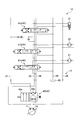
- FIG. 1 is a schematic diagram showing a circuit configuration of a typical hydraulic system using a travel switching valve, and shows a state before supplying hydraulic oil to a first actuator constituted by a dozer cylinder for driving a dozer.
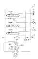
- FIG. 2 is a schematic diagram showing a circuit configuration of a typical hydraulic system using a travel switching valve, and shows a state where hydraulic oil is supplied to the first actuator.
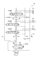
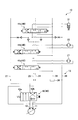
- FIG. 3 is a schematic diagram showing a circuit configuration of the hydraulic system according to the embodiment of the present invention, and shows a state where the first actuator is not driven.
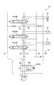
- FIG. 4 is a schematic diagram showing a circuit configuration of the hydraulic system according to the embodiment of the present invention, and shows a state in which the first actuator is driven.
- FIG. 1 is a schematic diagram showing a circuit configuration of a typical hydraulic system using a travel switching valve, and shows a state before supplying hydraulic oil to a first actuator constituted by a dozer cylinder for driving a dozer.
- FIG. 2 is a schematic diagram showing a
- FIG. 5 is a schematic diagram showing a circuit configuration of a hydraulic system according to an embodiment of the present invention, in which the first travel motor and the second travel motor are driven, the first actuator is not driven, and other actuators are driven. Indicates the state to be performed.
- FIG. 6 is a block diagram illustrating a relationship among the instruction receiving unit, the direction switching valve, and various actuators.
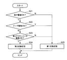
- FIG. 7 is a flowchart showing an outline of a determination flow of the first circuit state (see FIG. 4) and the second circuit state (see FIG. 3).
- FIG. 8 is a flowchart showing an outline of a flow for determining the switching state of the travel switching valve.
- FIG. 9 is a table showing the driving states of various actuators, the state of the travel switching valve, and the state of the hydraulic circuit in the first driving mode, the second driving mode, and the third driving mode.
- FIG. 10 is a block diagram showing the relationship between the logic system and the travel switching valve.
- FIG. 11 is a diagram illustrating an example of a hydraulic logic circuit of a logic system using hydraulic logic.
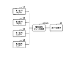
- FIG. 12 is a diagram illustrating an example of an electric signal logic circuit of a logic system using electric signal logic.
- FIG. 13 is a circuit diagram showing an example in which the hydraulic system according to one embodiment of the present invention is applied to a hydraulic excavator including a dozer.
- the hydraulic system described below is a system for driving two traveling motors and a dozer cylinder (that is, a first actuator) by two hydraulic pumps, and is less expensive and is uncomfortable during switching shocks and the like. This makes it possible to achieve comfortable operability.
- FIG. 1 is a schematic diagram showing a circuit configuration of a typical hydraulic system 10 using a travel switching valve 42, before supplying hydraulic oil to a first actuator 31 constituted by a dozer cylinder for driving the dozer. Shows the state.
- FIG. 2 is a schematic diagram showing a circuit configuration of a typical hydraulic system 10 using the travel switching valve 42, and shows a state in which hydraulic oil is supplied to the first actuator 31.
- the hydraulic system 10 shown in FIGS. 1 and 2 includes a first hydraulic pump 11 and a second hydraulic pump 12.
- the oil passage from the first hydraulic pump 11 branches into two oil passages, and one oil passage is connected to the second tandem passage 25. Further, the oil passage from the second hydraulic pump 12 branches into two oil passages, and one oil passage is connected to the first parallel passage 26.
- the other oil passage extending from the first hydraulic pump 11 and the other oil passage extending from the second hydraulic pump 12 are connected to the travel switching valve 42, and the connected oil passage is changed according to the switching state of the travel switching valve 42. Is done. That is, the travel switching valve 42 can be switched to either the first switching state 42a or the second switching state 42b, and changes the hydraulic circuit 13.
- the travel switching valve 42 is in the second switching state 42b, the other oil passage extending from the first hydraulic pump 11 is connected to the first tandem passage 24 via the travel switching valve 42, and from the second hydraulic pump 12
- the other extending oil passage is connected to the second parallel passage 27 via the travel switching valve 42.
- the travel switching valve 42 when the travel switching valve 42 is in the first switching state 42a, the other oil passage extending from the first hydraulic pump 11 is connected to the second parallel passage 27 via the travel switching valve 42, and the second hydraulic pump.
- the other oil passage extending from 12 is connected to the first tandem passage 24 via the travel switching valve 42.
- the first travel motor 21 and the second travel motor 22 are driven, and at least one of the first actuator 31 and other actuators connected to the first hydraulic pump 11 and the second hydraulic pump 12 via the hydraulic circuit 13.
- the travel switching valve 42 is placed in the second switching state 42b.
- the hydraulic oil from the first hydraulic pump 11 is supplied to the first traveling motor 21 via the first tandem passage 24, and the hydraulic oil from the first hydraulic pump 11 is supplied to the second via the second tandem passage 25. It is supplied to the traveling motor 22.
- the hydraulic oil from the second hydraulic pump 12 is supplied to the first actuator 31 via the second parallel passage 27, and the hydraulic oil from the second hydraulic pump 12 is supplied to the first parallel passage 26 and / or the second parallel passage 27. To be supplied to other actuators.
- first travel motor 21 and the second travel motor 22 are driven, and the first actuator 31 and other actuators connected to the first hydraulic pump 11 and the second hydraulic pump 12 through the hydraulic circuit 13 include
- the travel switching valve 42 is placed in the first switching state 42a.
- the hydraulic oil from the second hydraulic pump 12 is supplied to the first traveling motor 21 via the first tandem passage 24, and the hydraulic oil from the first hydraulic pump 11 is supplied to the second tandem passage 25 via the second tandem passage 25. It is supplied to the traveling motor 22.
- the direction switching valves 41a, 41b, and 41c are assigned to the first traveling motor 21, the second traveling motor 22, the first actuator 31, and the other actuators.
- Each direction switching valve 41a, 41b, 41c is provided with the supply of hydraulic oil to the assigned actuator (that is, the first travel motor 21, the second travel motor 22, the first actuator 31, or another actuator) and the supply of the hydraulic oil. It is possible to change the direction or adjust the supply amount of the hydraulic oil by narrowing the supply passage of the hydraulic oil.
- Each of the directional control valves 41a, 41b, and 41c shown in FIGS. 1 and 2 is configured as an eight-port three-position hydraulic pilot operating valve that has eight ports and can take three positions, and the middle position is hydraulic oil.
- the neutral position that is, the non-driving position
- the both end positions show the driving position where hydraulic oil is supplied. 1 and 2
- the right end position indicates the forward drive position
- the left end position indicates the reverse drive position. Accordingly, in FIG. 1, the direction switching valve 41 a assigned to the first travel motor 21 and the direction switching valve 41 b assigned to the second travel motor 22 are placed in the forward drive position and are assigned to the first actuator 31.
- the state where 41c is placed in the neutral position is shown.
- the direction switching valve 41 a assigned to the first traveling motor 21, the direction switching valve 41 b assigned to the second traveling motor 22, and the direction switching valve 41 c assigned to the first actuator 31 are in the forward drive position. The state of being placed in is shown. In FIGS. 1 and 2, the illustration of the directional control valve assigned to the other actuator is omitted.
- the hydraulic fluid discharged from the first travel motor 21, the second travel motor 22, the first actuator 31, and other actuators flows into the tank passage 29 via the direction switching valves 41 a, 41 b, 41 c and from the tank passage 29. It is discharged to the discharge tank 30.
- Each of the first tandem passage 24, the second tandem passage 25, the first parallel passage 26, and the second parallel passage 27 is connected to the tank passage 29 at the most downstream position.
- FIG. 3 is a schematic diagram illustrating a circuit configuration of the hydraulic system 10 according to an embodiment of the present invention, and illustrates a state where the first actuator 31 configured by a dozer cylinder is not driven.
- FIG. 4 is a schematic diagram showing a circuit configuration of the hydraulic system 10 according to the embodiment of the present invention, and shows a state in which the first actuator 31 configured by a dozer cylinder is driven.
- 3 and 4 are diagrams showing a circuit configuration in a case where an actuator other than the first traveling motor 21, the second traveling motor 22, and the first actuator 31 (that is, a “second actuator” described later) is not driven. is there. The case where the actuators other than the first traveling motor 21, the second traveling motor 22, and the first actuator 31 are driven will be described later (see FIG. 5 and the like).
- the hydraulic system 10 shown in FIGS. 3 and 4 also includes a first hydraulic pump 11 and a second hydraulic pump 12 that supply hydraulic oil, and a first traveling motor 21 and a second traveling that are driven according to the supplied hydraulic oil.
- a switching unit 40 a switching unit 40.
- the first hydraulic pump 11 and the second hydraulic pump 12 have the same output, and hydraulic oil having the same flow rate is supplied from the first hydraulic pump 11 and the second hydraulic pump 12 to the oil passage.
- the circuit switching unit 40 includes direction switching valves 41a, 41b, and 41c (8-port three-position hydraulic pressures) that are assigned to each actuator (that is, each of the first traveling motor 21, the second traveling motor 22, the first actuator 31, and the other actuators).
- a pilot operation valve and a travel switching valve 42.
- the first tandem passage 24, the second tandem passage 25, the first parallel passage 26, and the second passage are provided downstream of the first actuator 31. It is provided so as to be able to communicate with the parallel passage 27, and is constituted by one or a plurality of actuators (for example, a hydraulic motor or a hydraulic cylinder).
- actuators for example, a hydraulic motor or a hydraulic cylinder.
- other actuators that is, one or a plurality of actuators
- the second actuator is one or a plurality of actuators different from the first travel motor 21, the second travel motor 22, and the first actuator 31, and is driven according to the supplied hydraulic oil.
- the direction switching valve 41a is a direction switching valve for the first travel motor 21 and switches the presence / absence of supply of hydraulic fluid to the first travel motor 21 and the supply direction of hydraulic fluid.
- the direction switching valve 41b is a direction switching valve for the second traveling motor 22 and switches whether or not hydraulic oil is supplied to the second traveling motor 22 and the supply direction of the hydraulic oil.
- the direction switching valve 41 c is a direction switching valve for the first actuator 31, and switches whether hydraulic oil is supplied to the first actuator 31 and the supply direction of the hydraulic oil.
- a dedicated direction switching valve is also provided for the second actuator (that is, another actuator).
- the direction switching valve not only can switch the presence / absence of supply of hydraulic oil to the assigned actuator and the supply direction of hydraulic oil, but also adjusts the supply amount of hydraulic oil to the assigned actuator by narrowing the oil passage. You can also.
- the hydraulic system 10 includes a first tandem passage 24, a second tandem passage 25, a first parallel passage 26, and a second parallel passage 27.
- first tandem passage 24 and the second tandem passage 25 direction switching valves 41a, 41b, and 41c are provided in series.
- the hydraulic fluid flowing through each of the first tandem passage 24 and the second tandem passage 25 is caused to flow upstream (that is, closer to the first hydraulic pump 11 and the second hydraulic pump 12) by the direction switching valves 41a, 41b, and 41c. ) Can be preferentially supplied to the actuator.
- a branch path is formed in the middle of each of the first tandem passage 24 and the second tandem passage 25.
- the branch path is provided with a check valve that prevents the backflow of hydraulic oil from the downstream side to the upstream side, and is provided so as to be able to communicate with the first actuator 31 via the direction switching valve 41c.
- Each of the first parallel passage 26 and the second parallel passage 27 is also formed with a branch path, and the branch path is provided with a throttle and a check valve.
- the first actuator is connected via the direction switching valve 41c. 31 can be communicated.
- the first tandem passage 24, the second tandem passage 25, the first parallel passage 26, and the second parallel passage 27 are connected to the tank passage 29 in the most downstream portion.
- the hydraulic oil that has not been supplied to any actuator connected to the hydraulic circuit 13 finally flows into the tank passage 29 from these passages and is discharged from the tank passage 29 to the discharge tank 30.
- Each direction switching valve 41 a, 41 b, 41 c is also connected to the tank passage 29.
- the hydraulic fluid discharged from the actuators connected to the hydraulic circuit 13 (that is, the first travel motor 21, the second travel motor 22, the first actuator 31, and the second actuator) passes through the direction switching valves 41a, 41b, 41c. It flows into the tank passage 29 and is discharged from the tank passage 29 to the discharge tank 30.
- the traveling switching valve 42 is configured as a hydraulic pilot operating valve whose state is switched by a pilot pressure (hydraulic pressure).
- a pilot pressure hydraulic pressure
- the travel switching valve 42 When the travel switching valve 42 is placed in the first switching state 42a, the travel switching valve 42 connects the oil passage connected from the first hydraulic pump 11 to the travel switching valve 42 to the first tandem passage 24, and the second An oil passage connected from the hydraulic pump 12 to the travel switching valve 42 is connected to the second parallel passage 27. Therefore, when the travel switching valve 42 is placed in the first switching state 42a, the first hydraulic pump 11 supplies hydraulic oil to the first tandem passage 24 and the first parallel passage 26, and the second hydraulic pump 12 is connected to the second tandem passage. The hydraulic oil is supplied to 25 and the second parallel passage 27. As a result, hydraulic oil can be supplied from the first hydraulic pump 11 to at least the first travel motor 21, and hydraulic oil can be supplied from the second hydraulic pump 12 to at least the second travel motor 22. .
- the travel switching valve 42 when the travel switching valve 42 is placed in the second switching state 42b, the travel switching valve 42 connects an oil passage connected from the first hydraulic pump 11 to the travel switching valve 42 to the second parallel passage 27, and An oil passage connected from the second hydraulic pump 12 to the travel switching valve 42 is connected to the first tandem passage 24.
- the “oil passage to the second parallel passage 27” and the “oil passage to the first tandem passage 24” of the travel switching valve 42 in the second switching state 42b are connected to each other via a communication oil passage.
- the communication oil passage is provided with a throttle and a check valve so that hydraulic oil can flow from “the oil passage to the second parallel passage 27” to “the oil passage to the first tandem passage 24”. .
- the first hydraulic pump 11 mainly supplies hydraulic oil to the first parallel passage 26 and the second parallel passage 27, and the second hydraulic pump 12 is in the first tandem. Hydraulic fluid is supplied to the passage 24 and the second tandem passage 25.
- the hydraulic oil is supplied from the second hydraulic pump 12 to the first traveling motor 21 and the second traveling motor 22, and at least the second actuator (that is, downstream of the first actuator 31) is provided from the first hydraulic pump 11. It is possible to supply hydraulic oil to other actuators.
- the circuit switching unit 40 (that is, the direction switching valves 41a, 41b, 41c and the travel switching valve 42) of the present embodiment changes the hydraulic circuit 13 of the hydraulic system 10 to the following first circuit state and second circuit state.
- the first circuit state and the second circuit state described below are “when the first traveling motor 21 and the second traveling motor 22 are driven, the first actuator 31 is not driven, and other actuators are driven. It is realized in other cases.
- the travel switching valve 42 is placed in the first switching state 42a.
- the oil passage from the first hydraulic pump 11 is connected to each of the first tandem passage 24 and the first parallel passage 26, and the oil passage from the second hydraulic pump 12 is connected to the second tandem passage 25 and the second parallel passage 27. Lead to each.
- the direction switching valve 41c assigned to the first actuator 31 is placed in the drive position (the forward drive position on the right end side in the example shown in FIG. 4) in the first circuit state, and in the neutral position ( In the example shown in FIG.
- hydraulic fluid is supplied from the first hydraulic pump 11 to the first traveling motor 21 and the first actuator 31, and hydraulic fluid is supplied from the second hydraulic pump 12 to the second traveling motor 22 and the first actuator 31.
- Supply see FIG. 4
- hydraulic oil is supplied from the first hydraulic pump 11 to the first travel motor 21, and hydraulic oil is supplied from the second hydraulic pump 12 to the second travel motor 22.
- Hydraulic fluid is not supplied from the hydraulic pump 12 to the first actuator 31 (see FIG. 3).
- the circuit switching unit 40 is configured so that the flow rate of the hydraulic oil supplied to the first travel motor 21 is the flow rate of the hydraulic oil supplied to the second travel motor 22 in each of the first circuit state and the second circuit state described above.
- the hydraulic circuit can be changed to be equal.
- the travel switching valve 42 may not be provided.
- the oil passage extending from the first hydraulic pump 11 and the second hydraulic pump 12 can be configured similarly to the oil passage in the first switching state 42 a of the travel switching valve 42. That is, the oil passage from the first hydraulic pump 11 is connected to the first tandem passage 24 and the first parallel passage 26, and the oil passage from the second hydraulic pump 12 is connected to the second tandem passage 25 and the second parallel passage 27. can do.
- FIG. 5 is a schematic diagram illustrating a circuit configuration of the hydraulic system 10 according to an embodiment of the present invention, in which the first travel motor 21 and the second travel motor 22 are driven, the first actuator 31 is not driven, and the like. The state in which the actuator is driven is shown.
- the travel switching valve 42 is driven. Is placed in the second switching state 42b.
- the hydraulic oil from the second hydraulic pump 12 is supplied to the first traveling motor 21 via the first tandem passage 24, and the hydraulic oil from the second hydraulic pump 12 is secondly supplied to the second traveling motor 22.
- the hydraulic fluid from the first hydraulic pump is supplied to the second actuator via the first parallel passage 26 and / or the second parallel passage 27.
- the hydraulic circuit 13 is placed in the third circuit state, and hydraulic oil is supplied from the second hydraulic pump 12 to the first travel motor 21 and the second travel motor 22.
- the hydraulic oil is supplied to the first actuator 31, and the hydraulic oil is supplied from the first hydraulic pump 11 to the second actuator (that is, another actuator provided on the downstream side of the first actuator 31).
- FIG. 6 is a block diagram showing a relationship among the instruction receiving unit 50, the direction switching valve 41a, and various actuators.
- the hydraulic system 10 includes an instruction receiving unit 50 that receives an operation instruction from an operator.
- the instruction receiving unit 50 is provided in association with each actuator (that is, each of the first traveling motor 21, the second traveling motor 22, the first actuator 31, and the second actuator 32).
- indication reception part 50 is not specifically limited, Typically, the instruction
- the instruction receiving unit 50 of the present embodiment is associated with the first travel pedal 51 associated with the first travel motor 21, the second travel pedal 52 associated with the second travel motor 22, and the first actuator 31.
- a first operation lever 53 and a second operation lever 54 associated with the second actuator 32 are included. As described above, since the second actuator 32 collectively represents one or a plurality of actuators, the second operation lever 54 also collectively represents one or a plurality of levers.
- the operator can control the direction switching valve 41 a by operating the first travel pedal 51 to switch between driving and non-driving of the first traveling motor 21 and the driving state of the first traveling motor 21.
- the operator controls the direction switching valve 41b by operating the second traveling pedal 52, controls the direction switching valve 41c by operating the first operating lever 53, and operates the second operating lever 54.
- it is possible to control the direction switching valve 41d, and to control switching and driving states of the second traveling motor 22, the first actuator 31, and the second actuator 32. Therefore, when the dozer 33 is moved up and down, the operator may operate the first operation lever 53.
- FIG. 7 is a flowchart showing an outline of a determination flow of the first circuit state (see FIG. 4) and the second circuit state (see FIG. 3).
- FIG. 7 shows a circuit state determination flow based on the presence / absence of travel driving and the presence / absence of dozer driving. Therefore, the flowchart shown in FIG. 7 is based on the premise that the second actuator 32 (that is, another actuator provided downstream of the first actuator 31) is not driven. Note that the flow of determining the circuit state in consideration of whether or not the second actuator 32 is driven will be described later with reference to FIGS.
- the circuit switching unit 40 causes the hydraulic circuit 13 to be in the first circuit state. (S13).
- the circuit switching unit 40 causes the hydraulic circuit 13 to be connected to the second circuit. A state is set (S14).
- the circuit switching unit 40 changes the hydraulic circuit 13 based on the operation instruction received by the instruction receiving unit 50 (see FIG. 6), thereby realizing the first circuit state and the second circuit state.
- the circuit switching unit. 40 sets the hydraulic circuit 13 to the first circuit state.
- the circuit switching unit 40 is a hydraulic circuit. Let 13 be the second circuit state.
- FIG. 8 is a flowchart showing an outline of a flow for determining the switching state of the travel switching valve 42.
- the subsequent step S22 is performed.
- the drive mode of the hydraulic system 10 is a mode in which traveling driving is performed (Y in S21 in FIG. 8)
- the subsequent step S22 is performed.
- the drive mode of the hydraulic system 10 is not a mode for running driving (N in S21)
- the running switching valve 42 is placed in the first switching state 42a (S25).
- the traveling is performed regardless of whether the second actuator 32 is driven or not.
- the switching valve 42 is placed in the first switching state 42a (S25).
- the drive mode of the hydraulic system 10 is a mode in which driving is performed but is not a mode in which the dozer is driven by the first actuator 31 (N in S22)
- the following is performed depending on whether the second actuator 32 is driven or not.
- the switching state of the travel switching valve 42 is determined. That is, when the drive mode of the hydraulic system 10 is not the mode for driving the second actuator 32 (N in S23), the travel switching valve 42 is placed in the first switching state 42a (S25).
- the travel switching valve 42 is placed in the second switching state 42b (S24).
- the switching state of the travel switching valve 42 is determined, the states of the direction switching valves 41a, 41b, 41c are determined, and the hydraulic pressure The circuit 13 is changed to realize the first circuit state, the second circuit state, and the third circuit state.
- the operation instruction received by the instruction receiving unit 50 drives the first travel motor 21 and the second travel motor 22, drives the first actuator 31, and drives the second actuator 32, or does not drive the first drive mode.
- the travel switching valve 42 is placed in the first switching state 42a, and the circuit switching unit 40 places the hydraulic circuit 13 in the first circuit state.
- the operation instruction received by the instruction receiving unit 50 corresponds to the second driving mode in which the first traveling motor 21 and the second traveling motor 22 are driven and the first actuator 31 and the second actuator 32 are not driven.
- the travel switching valve 42 is placed in the first switching state 42a, and the circuit switching unit 40 places the hydraulic circuit 13 in the second circuit state.
- the operation instruction received by the instruction receiving unit 50 corresponds to the third drive mode in which the first travel motor 21 and the second travel motor 22 are driven, the first actuator 31 is not driven, and the second actuator 32 is driven. In this case, the travel switching valve 42 is placed in the second switching state 42b, and the circuit switching unit 40 places the hydraulic circuit 13 in the third circuit state.
- FIG. 9 is a table showing the driving states of various actuators, the state of the travel switching valve, and the state of the hydraulic circuit in the first driving mode, the second driving mode, and the third driving mode.
- the first travel motor 21 and the second travel motor 22 are driven, the first actuator 31 (that is, the dozer cylinder) is driven, and the second actuator 32 (that is, another actuator) is driven.
- the travel switching valve 42 is placed in the first switching state 42a, and the hydraulic circuit 13 is placed in the first circuit state.
- the second drive mode the first travel motor 21 and the second travel motor 22 are driven, the first actuator 31 is not driven, the second actuator 32 is not driven, and the travel switching valve 42 is in the first switching state 42a.
- the hydraulic circuit 13 is placed in the second circuit state.
- the third drive mode the first travel motor 21 and the second travel motor 22 are driven, the first actuator 31 is not driven, the second actuator 32 is driven, and the travel switching valve 42 is in the second switching state 42b.
- the hydraulic circuit 13 is placed in the third circuit state.
- FIG. 10 is a block diagram showing the relationship between the logic system 60 and the travel switching valve 42.
- the travel switching valve 42 is switched to the first switching state 42 a or the second switching state 42 b by the logic system 60.
- the logic system 60 performs switching control of the travel switching valve 42 in accordance with an operation instruction received by the instruction receiving unit 50 (see FIG. 6).
- the logic system 60 included in the hydraulic system 10 sets the travel switching valve 42 in the first switching state according to the driving states of the first traveling motor 21, the second traveling motor 22, the first actuator 31, and the second actuator 32. It is possible to switch between 42a and the second switching state 42b.
- the specific configuration of the logic system 60 is not particularly limited.
- the logic system 60 can be configured by a system using hydraulic logic or a system using electric signal logic.
- FIG. 11 is a diagram illustrating an example of the hydraulic logic circuit 61 of the logic system 60 using the hydraulic logic.
- a hydraulic pressure source 64 for the hydraulic logic circuit 61 that is, a pilot hydraulic pressure source.
- An oil passage extending from the hydraulic pressure source 64 is connected to a first travel motor logic valve 66, a second travel motor logic valve 67, a second actuator logic valve 68, and a dozer logic valve 69 through a throttle.
- the first travel motor logic valve 66, the second travel motor logic valve 67, the second actuator logic valve 68, and the dozer logic valve 69 are provided in parallel to the oil passage from the hydraulic source 64.
- Each has a mode for blocking the oil passage and a mode for communicating the oil passage to the discharge tank 70.
- the first travel motor logic valve 66 is interlocked with the drive mode of the first travel motor 21, the second travel motor logic valve 67 is interlocked with the drive mode of the second travel motor 22, and the second actuator logic valve 68 is In conjunction with the drive mode of the second actuator 32, the dozer logic valve 69 is linked to the drive mode of the first actuator 31.
- the symbols “66a”, “67a”, “68a”, and “69a” in FIG. 11 represent states when the corresponding actuators are driven in the forward direction, and the symbols “66c”, “67c”, “68c”, and “69c”.
- the oil is supplied from the hydraulic source 64 to the oil passage.
- the pressure oil is discharged to the discharge tank 70, and no pilot pressure is generated in the oil passage at the position indicated by the symbol “A” in FIG. Therefore, the pilot pressure does not act on the travel switching valve 42, and the travel switching valve 42 is placed in the first switching state 42a.
- the pressure of the pressure oil in the hydraulic logic circuit 61 changes according to the driving states of the first traveling motor 21, the second traveling motor 22, the first actuator 31, and the second actuator 32.
- the logic system 60 switches the travel switching valve 42 between the first switching state 42a and the second switching state 42b based on the pressure (that is, hydraulic pressure) of the pressure oil in the hydraulic logic circuit 61.
- FIG. 12 is a diagram illustrating an example of the electric signal logic circuit 62 of the logic system 60 using the electric signal logic.
- each of the first travel pedal 51, the second travel pedal 52, the first operation lever 53, and the second operation lever 54 sends an electrical signal corresponding to the operation state of the operator to the electrical signal logic circuit 62.
- each of the first travel pedal 51, the second travel pedal 52, the first operation lever 53, and the second operation lever 54 here is not only an operation portion that is directly operated by an operator, but also the operation portion.
- a signal generation unit that sends an electric signal corresponding to the operation to the electric signal logic circuit 62 is also included.
- the electrical signal logic circuit 62 sets the travel switching valve 42 as described above according to the electrical signals sent from the first travel pedal 51, the second travel pedal 52, the first operation lever 53, and the second operation lever 54. Switch to either the first switching state 42a or the second switching state 42b.
- the signal flowing through the electric signal logic circuit 62 changes according to the driving state of the first traveling motor 21, the second traveling motor 22, the first actuator 31, and the second actuator 32.
- the logic system 60 switches the travel switching valve 42 between the first switching state 42a and the second switching state 42b based on these signals flowing through the electric signal logic circuit 62.
- FIG. 13 is a circuit diagram showing an example in which the hydraulic system 10 according to the above-described embodiment of the present invention is applied to a hydraulic excavator equipped with a dozer.
- a hydraulic excavator includes a lower frame having a crawler, an upper frame provided so as to be rotatable with respect to the lower frame, a boom attached to the upper frame, an arm attached to the boom, and a bucket attached to the arm.
- the hydraulic excavator according to the present embodiment further includes a dozer for extruding deposits such as earth and sand and snow.
- the first hydraulic pump 11 is similar to the hydraulic system 10 shown in FIGS. , Second hydraulic pump 12, first tandem passage 24, second tandem passage 25, first parallel passage 26, second parallel passage 27, tank passage 29, travel switching valve 42, direction switching valves 41a, 41b, 41c, 41d
- the first travel motor 21, the second travel motor 22, and the first actuator 31 are provided.
- a hydraulic motor for turning the upper frame with respect to the lower frame is illustrated as the second actuator 32.
- an actuator for example, a hydraulic cylinder
- an actuator for boom swing and other service actuators may be provided.
- FIG. 13 shows a main system hydraulic circuit 13a (see a solid line) for flowing hydraulic oil for driving various actuators and a pressure oil for operating a valve state operation and other states.
- An operation system hydraulic circuit 13b (see dotted line) is shown.
- the signs “Pa1” and “Pb1” in FIG. 13 connected to the operation system hydraulic circuit 13b are pilot pressures used to change the state (position) of the direction switching valve 41a for the first travel motor 21.
- the inflow / outflow port of the pressure oil which gives to the direction switching valve 41a is shown.
- symbols “Pa2” and “Pb2” indicate pilot pressure oil inflow / outflow ports used for changing the state of the direction switching valve 41b for the second traveling motor 22, and symbols “Pa3” and “Pb3”.
- Fig. 4 shows the pilot pressure oil inflow / outflow ports used to change the state of 41d.
- a symbol “Pp” in FIG. 13 indicates an inflow port of pilot pressure oil for supplying pressure oil (that is, pilot pressure oil) that provides a pilot pressure to the operation system hydraulic circuit 13b, and a symbol “Dr1” indicates the operation system.
- a drain port for discharging pilot pressure oil from the hydraulic circuit 13b is shown.
- an auto idle system 80, a parking brake system 81, and a logic system 60 are connected to the operation system hydraulic circuit 13b.
- the auto idle system 80 is a system for generating a pilot pressure.
- the pilot pressure can be generated in the operation system hydraulic circuit 13b.
- the parking brake system 81 is a system for controlling on / off of a parking brake (not shown) for braking the turning operation.
- the parking brake system 81 can turn off the parking brake and release the braking of the turning operation. .
- the direction switching valves 41a, 41b, 41c, and 41d shown in FIG. 13 are connected not only to the oil passage of the main system hydraulic circuit 13a but also to the oil passage of the operation system hydraulic circuit 13b, and the operation that flows through the main system hydraulic circuit 13a.
- the flow of pressure oil flowing through the oil and operation system hydraulic circuit 13b and the supply oil passage for these hydraulic oil and pressure oil are controlled.
- a portion that controls the hydraulic oil in the main system hydraulic circuit 13a and a portion that controls the pressure oil in the operation system hydraulic circuit 13b are linked to each other.
- the state of the operation system hydraulic circuit 13b changes according to the driving state of the first travel motor 21, the second travel motor 22, the first actuator 31, the second actuator 32, etc., and is connected to the operation system hydraulic circuit 13b.
- the control states of various systems such as the auto idle system 80, the parking brake system 81, and the logic system 60 also change.
- the direction switching valves 41a, 41b, 41c, and 41d can be realized by an arbitrary valve device, and the direction switching valves 41a, 41b, 41c, and 41d can be typically configured by spool valves.
- the travel switching valve 42 can also be realized by an arbitrary valve device. Typically, the travel switching valve 42 can be configured by a spool valve.
- the direction switching valves 41a, 41b, 41c, 41d and the travel switching valves having the functions symbolically shown in FIGS. 3 to 5 and FIG. 13 are devised by devising the land portion, notch portion, notch and the like formed on the spool. 42 can be realized. Accordingly, the hydraulic circuit 13 shown in FIG.
- main system hydraulic circuit 13a and the operation system hydraulic circuit 13b can be obtained by a person skilled in the art having ordinary knowledge by, for example, a monoblock type valve body including a plurality of spool valves. It is possible to configure.
- three or more actuators including two travel motors and a dozer cylinder (in the above-described embodiment, the first travel motor 21, the second travel motor 22, the first actuator). 31 and the second actuator 32) can be appropriately driven and controlled by only two hydraulic pumps.
- the traveling switching valve 42 When only the first traveling motor 21 and the second traveling motor 22 are driven and only traveling is performed, the traveling switching valve 42 is placed in the first switching state 42a and the hydraulic circuit 13 is brought into the first circuit state.
- the hydraulic oil is supplied to only one traveling motor from one hydraulic pump.
- the travel switching valve 42 when the first actuator 31 is driven to operate the dozer, the travel switching valve 42 is placed in the first switching state 42a regardless of whether other actuators are driven or not, and the hydraulic circuit 13 is in the first state.
- hydraulic fluid In a circuit state, hydraulic fluid is supplied from only one hydraulic pump to one traveling motor.
- the hydraulic oil is supplied only from one hydraulic pump to one traveling motor. Therefore, switching according to switching between driving and non-driving of the dozer. Shock does not occur and operability is good.
- the present invention is not limited to the above-described embodiments and modifications. For example, various modifications may be made to the elements of the above-described embodiments and modifications. In addition, embodiments including components other than the above-described components are also included in the embodiments of the present invention. Further, a form in which some of the above-described components are not included is also included in the embodiment of the present invention. In addition, embodiments including some components included in an embodiment of the present invention and some components included in another embodiment of the present invention are also included in the embodiment of the present invention. Therefore, the constituent elements included in each of the embodiments and modifications described above and the embodiments of the present invention other than those described above may be combined with each other, and embodiments related to such combinations are also included in the embodiments of the present invention. .
- the effect produced by the present invention is not limited to the above-described effect, and a specific effect corresponding to the specific configuration of each embodiment can be exhibited.
- various additions, modifications, and partial deletions may be made to each element described in the claims, the description, the abstract, and the drawings without departing from the technical idea and spirit of the present invention. It is.
- First switching state, 42b ... 2nd switching state, 50 ... Instruction receiving part, 51 ... 1st travel pedal, 52 ... 2nd travel pedal, 53 ... 1st operation lever, 54 ... 2nd operation lever, 60 ... Logic system, 61 Hydraulic logic circuit, 62 ... electric signal logic circuit, 64 ... hydraulic power source, 66 ... first travel motor logic valve, 67 ... second travel motor logic valve, 68 ... second actuator logic valve, 69 ... dozer logic Valve, 70 ... Discharge tank, 80 ... Auto idle system, 81 ... Parking brake system
Landscapes
- Engineering & Computer Science (AREA)
- General Engineering & Computer Science (AREA)
- Physics & Mathematics (AREA)
- Fluid Mechanics (AREA)
- Mechanical Engineering (AREA)
- Mining & Mineral Resources (AREA)
- Civil Engineering (AREA)
- Structural Engineering (AREA)
- Operation Control Of Excavators (AREA)
- Fluid-Pressure Circuits (AREA)
Abstract
コストを抑えつつ快適な操作性を実現できる油圧システムを提供する。油圧システム(10)は、第1油圧ポンプ(11)及び第2油圧ポンプ(12)と、第1走行モータ(21)及び第2走行モータ(22)と、ドーザを駆動する第1アクチュエータ(31)と、回路切換部(40)とを備える。回路切換部(40)は、油圧回路(13)を第1回路状態及び第2回路状態に変更する。第1回路状態では、第1油圧ポンプ(11)から第1走行モータ(21)及び第1アクチュエータ(31)に作動油が供給され、第2油圧ポンプ(12)から第2走行モータ(22)及び第1アクチュエータ(31)に作動油が供給される。第2回路状態では、第1油圧ポンプ(11)から第1走行モータ(21)に作動油が供給され、第2油圧ポンプ(12)から第2走行モータ(22)に作動油が供給され、第1油圧ポンプ(11)及び第2油圧ポンプ(12)から第1アクチュエータ(31)に作動油が供給されない。
Description
本発明は、走行モータとドーザを駆動するアクチュエータとを備える油圧システムに関する。
走行モータとドーザを昇降させるドーザシリンダとを備える油圧システムとして、例えば特許文献1が開示する装置が知られている。この装置は、一対の走行油圧モータに圧油(すなわち作動油)を供給する2つのメインポンプと、ドーザシリンダに圧油を供給するドーザポンプとを備える。
特許文献1の装置のように走行モータの駆動に用いるポンプとは別個にドーザシリンダの駆動に用いるポンプを設けることで、ドーザシリンダの駆動が走行モータの駆動に影響を及ぼさない。しかしながら、ドーザシリンダを駆動するための専用ポンプを設ける必要があるため、コストが増大してしまう。
一方、走行モータの駆動及びドーザの駆動に共通のポンプを用いる方法として、2つのポンプを使用し、一方のポンプからの作動油を一方の走行モータに供給しつつ、他方のポンプからの作動油を他方の走行モータ及びドーザシリンダに供給する方法が考えられる。しかしながら、この方法では、ドーザシリンダを駆動する場合には左右の走行モータ間において作動油の供給量に差が生じ、直進走行を行うことが難しくなり、操作性が悪い。
走行モータの駆動及びドーザの駆動に共通のポンプを用いる他の方法として、走行切換弁を利用する方法が考えられる。走行切換弁は、駆動モードに応じて各ポンプからの作動油の供給先を切り換える弁である。例えばドーザが駆動されず走行モータの駆動のみが行われる場合、第1のポンプから一方の走行モータに作動油を供給しつつ第2のポンプから他方の走行モータに作動油を供給するように、走行切換弁は油圧回路を切り換える。一方、走行モータの駆動及びドーザの駆動が同時に行われる場合、第1のポンプから両方の走行モータに作動油を供給しつつ第2のポンプからドーザ駆動用のアクチュエータに作動油を供給するように、走行切換弁は油圧回路を切り換える。
このような走行切換弁を用いることによって、ドーザ駆動のための専用ポンプが不要になるが、2つのポンプによって2つの走行モータを駆動する状態と1つのポンプによって2つの走行モータを駆動する状態との間で、油圧回路を切り換える必要がある。このような油圧回路の切り換え時には、走行モータに対するポンプの割り当ての状態が変化することに伴う衝撃(すなわち切換ショック)が操作者に作用し、油圧回路を切り換えるたびに操作者に対して不快感がもたらされる。特に、ドーザの上昇駆動及び下降駆動を切り換えるたびに、走行切換弁によって油圧回路を切り換える必要がある場合には、油圧回路の切り換えに伴って走行速度の変化及び切換ショックが生じるため、操作性が非常に悪い。
本発明は上述の事情に鑑みてなされたものであり、コストを抑えつつ快適な操作性を実現することができる油圧システムを提供することを目的とする。
本発明の一態様は、作動油を供給する第1油圧ポンプ及び第2油圧ポンプと、供給される作動油に応じて駆動される第1走行モータ及び第2走行モータと、供給される作動油に応じてドーザを駆動する第1アクチュエータと、油圧回路を変更して、第1油圧ポンプ及び第2油圧ポンプからの作動油の供給先を切り換える回路切換部と、を備え、回路切換部は、第1油圧ポンプから第1走行モータ及び第1アクチュエータに作動油を供給し、第2油圧ポンプから第2走行モータ及び第1アクチュエータに作動油を供給する第1回路状態と、第1油圧ポンプから第1走行モータに作動油を供給し、第2油圧ポンプから第2走行モータに作動油を供給し、第1油圧ポンプ及び第2油圧ポンプから第1アクチュエータに作動油を供給しない第2回路状態と、に油圧回路を変更する油圧システムに関する。
回路切換部は、第1回路状態及び第2回路状態の各々において、第1走行モータに供給される作動油の流量が第2走行モータに供給される作動油の流量と等しくなるように油圧回路を変更してもよい。
油圧システムは、操作指示を受け付ける指示受付部を更に備え、回路切換部は、指示受付部が受け付けた操作指示が、第1走行モータ及び第2走行モータを駆動しつつ第1アクチュエータを駆動するモードに対応する場合には、油圧回路を第1回路状態とし、指示受付部が受け付けた操作指示が、第1走行モータ及び第2走行モータを駆動するが第1アクチュエータを駆動しないモードに対応する場合には、油圧回路を第2回路状態としてもよい。
油圧システムは、第1アクチュエータとは異なる第2アクチュエータであって、供給される作動油に応じて駆動される第2アクチュエータを更に備え、回路切換部は走行切換弁を含み、走行切換弁は、第1油圧ポンプから少なくとも第1走行モータに作動油を供給し、第2油圧ポンプから少なくとも第2走行モータに作動油を供給する第1切換状態と、第2油圧ポンプから第1走行モータ及び第2走行モータに作動油を供給しつつ、第1油圧ポンプから少なくとも第2アクチュエータに作動油を供給する第2切換状態と、にされ、油圧回路を第1回路状態及び第2回路状態のいずれかにする場合には、走行切換弁は第1切換状態にされ、油圧回路を、第2油圧ポンプから第1走行モータ及び第2走行モータに作動油を供給し、第1アクチュエータに作動油を供給せず、第1油圧ポンプから第2アクチュエータに作動油を供給する第3回路状態にする場合には、走行切換弁は第2切換状態にされてもよい。
油圧システムは、操作指示を受け付ける指示受付部を更に備え、回路切換部は、指示受付部が受け付けた操作指示が、第1走行モータ及び第2走行モータを駆動し、第1アクチュエータを駆動し、第2アクチュエータを駆動し又は駆動しない第1駆動モードに対応する場合には、油圧回路を第1回路状態とし、指示受付部が受け付けた操作指示が、第1走行モータ及び第2走行モータを駆動し、第1アクチュエータ及び第2アクチュエータを駆動しない第2駆動モードに対応する場合には、油圧回路を第2回路状態とし、指示受付部が受け付けた操作指示が、第1走行モータ及び第2走行モータを駆動し、第1アクチュエータを駆動せず、第2アクチュエータを駆動する第3駆動モードに対応する場合には、油圧回路を第3回路状態とするように、油圧回路を変更してもよい。
油圧システムは、第1走行モータ、第2走行モータ、第1アクチュエータ及び第2アクチュエータの駆動状態に応じて、走行切換弁を第1切換状態と第2切換状態との間で切り換えるためのロジックシステムを更に備えてもよい。
ロジックシステムは、油圧ロジック回路を有し、油圧ロジック回路内の圧油の圧力は、第1走行モータ、第2走行モータ、第1アクチュエータ及び第2アクチュエータの駆動状態に応じて変化し、ロジックシステムは、油圧ロジック回路内の圧油に基づいて、走行切換弁を第1切換状態と第2切換状態との間で切り換えてもよい。
ロジックシステムは、電気信号ロジック回路を有し、電気信号ロジック回路を流れる信号は、第1走行モータ、第2走行モータ、第1アクチュエータ及び第2アクチュエータの駆動状態に応じて変化し、ロジックシステムは、電気信号ロジック回路を流れる信号に基づいて、走行切換弁を第1切換状態と第2切換状態との間で切り換えてもよい。
回路切換部は、第1走行モータに対する作動油の供給の有無及び作動油の供給方向を切り換える第1走行モータ用方向切換弁と、第2走行モータに対する作動油の供給の有無及び作動油の供給方向を切り換える第2走行モータ用方向切換弁と、第1アクチュエータに対する作動油の供給の有無及び作動油の供給方向を切り換える第1アクチュエータ用方向切換弁と、を含んでもよい。
本発明によれば、コストを抑えつつ快適な操作性を実現することができる油圧システムを提供することができる。
以下、図面を参照して本発明の一実施形態について説明する。以下に説明する油圧システムは、2つの油圧ポンプによって、2つの走行モータ及びドーザシリンダ(すなわち第1アクチュエータ)を駆動するためのシステムであり、コストを抑えつつ、切換ショック等の操作時の不快感を低減して快適な操作性を実現することができる。
まず、本発明の実施形態と比較される「走行切換弁を用いた典型的な油圧システム」について説明する。
図1は、走行切換弁42を用いた典型的な油圧システム10の回路構成を示す概略図であり、ドーザを駆動するためのドーザシリンダによって構成される第1アクチュエータ31に作動油を供給する前の状態を示す。図2は、走行切換弁42を用いた典型的な油圧システム10の回路構成を示す概略図であり、第1アクチュエータ31に作動油を供給している状態を示す。
図1及び図2に示す油圧システム10は第1油圧ポンプ11及び第2油圧ポンプ12を備える。第1油圧ポンプ11からの油路は2つの油路に分岐し、一方の油路が第2タンデム通路25につながっている。また第2油圧ポンプ12からの油路は2つの油路に分岐し、一方の油路が第1パラレル通路26につながっている。
第1油圧ポンプ11から延びる他方の油路及び第2油圧ポンプ12から延びる他方の油路は、走行切換弁42に接続され、走行切換弁42の切換状態に応じて接続される油路が変更される。すなわち、走行切換弁42は第1切換状態42a及び第2切換状態42bのいずれかに切り換え可能であり、油圧回路13を変更する。走行切換弁42が第2切換状態42bに置かれている場合、第1油圧ポンプ11から延びる他方の油路は走行切換弁42を介して第1タンデム通路24につながり、第2油圧ポンプ12から延びる他方の油路は走行切換弁42を介して第2パラレル通路27につながる。一方、走行切換弁42が第1切換状態42aに置かれている場合、第1油圧ポンプ11から延びる他方の油路は走行切換弁42を介して第2パラレル通路27につながり、第2油圧ポンプ12から延びる他方の油路は走行切換弁42を介して第1タンデム通路24につながる。
第1走行モータ21及び第2走行モータ22が駆動され、且つ、油圧回路13を介して第1油圧ポンプ11及び第2油圧ポンプ12に接続されている第1アクチュエータ31及び他のアクチュエータの少なくともいずれかが駆動される場合、走行切換弁42は、第2切換状態42bに置かれる。この場合、第1油圧ポンプ11からの作動油が第1タンデム通路24を介して第1走行モータ21に供給され、第1油圧ポンプ11からの作動油が第2タンデム通路25を介して第2走行モータ22に供給される。また第2油圧ポンプ12からの作動油が第2パラレル通路27を介して第1アクチュエータ31に供給され、第2油圧ポンプ12からの作動油が第1パラレル通路26及び/又は第2パラレル通路27を介して他のアクチュエータに供給される。
一方、第1走行モータ21及び第2走行モータ22が駆動され、且つ、油圧回路13を介して第1油圧ポンプ11及び第2油圧ポンプ12に接続されている第1アクチュエータ31及び他のアクチュエータがいずれも駆動されない場合、走行切換弁42は、第1切換状態42aに置かれる。この場合、第2油圧ポンプ12からの作動油が第1タンデム通路24を介して第1走行モータ21に供給され、第1油圧ポンプ11からの作動油が第2タンデム通路25を介して第2走行モータ22に供給される。
また第1走行モータ21、第2走行モータ22、第1アクチュエータ31及び他のアクチュエータの各々に対しては、方向切換弁41a、41b、41cが割り当てられている。各方向切換弁41a、41b、41cは、割り当てられたアクチュエータ(すなわち第1走行モータ21、第2走行モータ22、第1アクチュエータ31又は他のアクチュエータ)に対する作動油の供給の有無及び作動油の供給方向を切り換えたり、作動油の供給路を絞って作動油の供給量を調整したりすることができる。
図1及び図2に示す方向切換弁41a、41b、41cの各々は、8個のポートを持ち3つの位置をとることができる8ポート3位置油圧パイロット作動弁として構成され、真ん中位置が作動油の供給を停止する中立位置(すなわち非駆動位置)を示し、両端位置が作動油の供給を行う駆動位置を示す。図1及び図2では右側端位置が順方向駆動位置を示し、左側端位置が逆方向駆動位置を示す。したがって図1には、第1走行モータ21に割り当てられる方向切換弁41a及び第2走行モータ22に割り当てられる方向切換弁41bが順方向駆動位置に置かれ、第1アクチュエータ31に割り当てられる方向切換弁41cが中立位置に置かれている状態が示されている。一方、図2には、第1走行モータ21に割り当てられる方向切換弁41a、第2走行モータ22に割り当てられる方向切換弁41b及び第1アクチュエータ31に割り当てられる方向切換弁41cが、順方向駆動位置に置かれている状態が示されている。なお図1及び図2において、他のアクチュエータに割り当てられている方向切換弁の図示は省略されている。
第1走行モータ21、第2走行モータ22、第1アクチュエータ31及び他のアクチュエータから排出される作動油は、方向切換弁41a、41b、41cを介してタンク通路29に流入し、タンク通路29から排出タンク30に排出される。また第1タンデム通路24、第2タンデム通路25、第1パラレル通路26及び第2パラレル通路27の各々は、最下流位置においてタンク通路29に接続されている。
このように、上述の走行切換弁42を用いた典型的な油圧システム10では、走行しながらドーザを上下駆動する際には、1つの油圧ポンプ(図1及び図2では第1油圧ポンプ11)から第1走行モータ21及び第2走行モータ22に作動油が供給される。一方、第1アクチュエータ31及び他のアクチュエータを駆動せず第1走行モータ21及び第2走行モータ22のみを駆動する際には、2つの油圧ポンプから第1走行モータ21及び第2走行モータ22に作動油が供給される。そのため、ドーザの駆動及び非駆動を細かく切り換える場合には、走行切換弁42の状態も細かく切り換えられ、ドーザの駆動及び非駆動を切り換えるたびに切換ショックが発生し、操作性が非常に悪い。
一方、下記の本発明の一実施形態に係る油圧システム10によれば、2つの油圧ポンプによって2つの走行モータ及びドーザシリンダを駆動され、そのような切換ショックの発生が低減されており、低コスト化と快適な操作性の実現とを両立させることができる。
図3は、本発明の一実施形態に係る油圧システム10の回路構成を示す概略図であり、ドーザシリンダによって構成される第1アクチュエータ31が駆動されない状態を示す。図4は、本発明の一実施形態に係る油圧システム10の回路構成を示す概略図であり、ドーザシリンダによって構成される第1アクチュエータ31が駆動される状態を示す。なお図3及び図4は、第1走行モータ21、第2走行モータ22及び第1アクチュエータ31以外の他のアクチュエータ(すなわち後述の「第2アクチュエータ」)が駆動されない場合の回路構成を示す図である。第1走行モータ21、第2走行モータ22及び第1アクチュエータ31以外の他のアクチュエータが駆動される場合については、後述する(図5等参照)。
図3及び図4に示す油圧システム10も、作動油を供給する第1油圧ポンプ11及び第2油圧ポンプ12と、供給される作動油に応じて駆動される第1走行モータ21及び第2走行モータ22と、供給される作動油に応じてドーザを駆動する第1アクチュエータ31と、油圧回路を変更して、第1油圧ポンプ11及び第2油圧ポンプ12からの作動油の供給先を切り換える回路切換部40とを備える。第1油圧ポンプ11及び第2油圧ポンプ12は、同じ出力を有し、第1油圧ポンプ11及び第2油圧ポンプ12から同じ流量の作動油が油路に供給される。回路切換部40は、各アクチュエータ(すなわち第1走行モータ21、第2走行モータ22、第1アクチュエータ31及び他のアクチュエータの各々)に割り当てられる方向切換弁41a、41b、41c(8ポート3位置油圧パイロット作動弁)と、走行切換弁42とを有する。
なお、他のアクチュエータは、図3及び図4において図示が省略されているが、第1アクチュエータ31よりも下流側において第1タンデム通路24、第2タンデム通路25、第1パラレル通路26及び第2パラレル通路27に連通可能に設けられており、1又は複数のアクチュエータ(例えば油圧モータ又は油圧シリンダ等)によって構成されている。以下、他のアクチュエータ(すなわち1又は複数のアクチュエータ)を総称して「第2アクチュエータ」とも呼ぶ。すなわち第2アクチュエータは、第1走行モータ21、第2走行モータ22及び第1アクチュエータ31とは異なる1又は複数のアクチュエータであって、供給される作動油に応じて駆動される。
方向切換弁41aは、第1走行モータ21用の方向切換弁であり、第1走行モータ21に対する作動油の供給の有無及び作動油の供給方向を切り換える。方向切換弁41bは、第2走行モータ22用の方向切換弁であり、第2走行モータ22に対する作動油の供給の有無及び作動油の供給方向を切り換える。方向切換弁41cは、第1アクチュエータ31用の方向切換弁であり、第1アクチュエータ31に対する作動油の供給の有無及び作動油の供給方向を切り換える。第2アクチュエータ(すなわち他のアクチュエータ)に対しても、専用の方向切換弁が設けられている。なお方向切換弁は、割り当てられたアクチュエータに対する作動油の供給の有無及び作動油の供給方向を切り換えることができるだけではなく、油路を絞って割り当てられたアクチュエータに対する作動油の供給量を調整することもできる。
油圧システム10は、第1タンデム通路24、第2タンデム通路25、第1パラレル通路26及び第2パラレル通路27を含む。第1タンデム通路24及び第2タンデム通路25の各々には、方向切換弁41a、41b、41cが直列的に設けられている。これにより、第1タンデム通路24及び第2タンデム通路25の各々を流れる作動油は、方向切換弁41a、41b、41cによって、上流側(すなわち第1油圧ポンプ11及び第2油圧ポンプ12に近い側)のアクチュエータに優先的に供給可能となっている。
例えば、図3及び図4に示す油圧システム10では、方向切換弁41aが駆動位置(すなわち図3の右側の順方向駆動位置又は図3の左側の逆方向駆動位置)に置かれた場合、第1タンデム通路24から第1走行モータ21に作動油が供給される。そのため、第1タンデム通路24を流れる作動油は、第1走行モータ21よりも下流側に設けられるアクチュエータ(すなわち第2走行モータ22、第1アクチュエータ31及び他のアクチュエータ)には供給されない。また方向切換弁41bが駆動位置(すなわち図3の右側の順方向駆動位置又は図3の左側の逆方向駆動位置)に置かれた場合、第2タンデム通路25から第2走行モータ22に作動油が供給される。そのため、第2タンデム通路25を流れる作動油は、第2走行モータ22よりも下流側に設けられるアクチュエータ(すなわち第1アクチュエータ31及び他のアクチュエータ)には供給されない。
方向切換弁41bと方向切換弁41cとの間において、第1タンデム通路24及び第2タンデム通路25の各々には途中で分岐路が形成されている。当該分岐路は、下流側から上流側への作動油の逆流を防ぐ逆止弁が設けられており、方向切換弁41cを介して第1アクチュエータ31に連通可能に設けられている。また第1パラレル通路26及び第2パラレル通路27の各々にも途中で分岐路が形成され、当該分岐路は、絞り及び逆止弁が設けられており、方向切換弁41cを介して第1アクチュエータ31に連通可能に設けられている。第1タンデム通路24、第2タンデム通路25、第1パラレル通路26及び第2パラレル通路27の各々に設けられるこれらの分岐路は、相互に合流した後に方向切換弁41cに接続されている。
第1タンデム通路24、第2タンデム通路25、第1パラレル通路26及び第2パラレル通路27は、最下流部においてタンク通路29につながっている。油圧回路13に接続されるいずれのアクチュエータにも供給されなかった作動油は、最終的にはこれらの通路からタンク通路29に流れ込んで、タンク通路29から排出タンク30に排出される。また各方向切換弁41a、41b、41cもタンク通路29に接続されている。油圧回路13につながっているアクチュエータ(すなわち第1走行モータ21、第2走行モータ22、第1アクチュエータ31及び第2アクチュエータ)から排出された作動油は、方向切換弁41a、41b、41cを介してタンク通路29に流れ込み、タンク通路29から排出タンク30に排出される。
走行切換弁42は、パイロット圧(油圧)によって状態が切り換えられる油圧パイロット作動弁として構成されている。パイロット圧が走行切換弁42に作用していない場合には走行切換弁42は第1切換状態42aに置かれ、パイロット圧が走行切換弁42に作用している場合には走行切換弁42は第2切換状態42bに置かれる。
走行切換弁42が第1切換状態42aに置かれる場合、走行切換弁42は、第1油圧ポンプ11から走行切換弁42に接続される油路を第1タンデム通路24に接続するとともに、第2油圧ポンプ12から走行切換弁42に接続される油路を第2パラレル通路27に接続する。したがって走行切換弁42が第1切換状態42aに置かれる場合、第1油圧ポンプ11は第1タンデム通路24及び第1パラレル通路26に作動油を供給し、第2油圧ポンプ12は第2タンデム通路25及び第2パラレル通路27に作動油を供給する。これにより、第1油圧ポンプ11から少なくとも第1走行モータ21に作動油を供給することが可能となり、また第2油圧ポンプ12から少なくとも第2走行モータ22に作動油を供給することが可能になる。
一方、走行切換弁42が第2切換状態42bに置かれる場合、走行切換弁42は、第1油圧ポンプ11から走行切換弁42に接続される油路を第2パラレル通路27に接続するとともに、第2油圧ポンプ12から走行切換弁42に接続される油路を第1タンデム通路24に接続する。なお、第2切換状態42bの走行切換弁42が有する「第2パラレル通路27への油路」と「第1タンデム通路24への油路」とは連絡油路を介して相互に接続されている。当該連絡油路には絞り及び逆止弁が設けられ、「第2パラレル通路27への油路」から「第1タンデム通路24への油路」への作動油の流入が可能となっている。したがって走行切換弁42が第2切換状態42bに置かれる場合、第1油圧ポンプ11は主として第1パラレル通路26及び第2パラレル通路27に作動油を供給し、第2油圧ポンプ12は第1タンデム通路24及び第2タンデム通路25に作動油を供給する。これにより、第2油圧ポンプ12から第1走行モータ21及び第2走行モータ22に作動油を供給しつつ、第1油圧ポンプ11から少なくとも第2アクチュエータ(すなわち第1アクチュエータ31よりも下流側に設けられる他のアクチュエータ)に作動油を供給することが可能になる。
本実施形態の回路切換部40(すなわち方向切換弁41a、41b、41c及び走行切換弁42)は、以下の第1回路状態と第2回路状態とに、油圧システム10の油圧回路13を変更する。なお、以下に説明する第1回路状態及び第2回路状態は、「第1走行モータ21及び第2走行モータ22が駆動され、第1アクチュエータ31が駆動されず、他のアクチュエータが駆動される場合」以外の場合に実現される。
すなわち、油圧回路13を第1回路状態(図4参照)及び第2回路状態(図3参照)のいずれかにする場合には、走行切換弁42は第1切換状態42aに置かれる。これにより、第1油圧ポンプ11からの油路が第1タンデム通路24及び第1パラレル通路26の各々につながり、第2油圧ポンプ12からの油路が第2タンデム通路25及び第2パラレル通路27の各々につながる。ただし、第1アクチュエータ31に割り当てられた方向切換弁41cは、第1回路状態では駆動位置(図4に示す例では右端側の順方向駆動位置)に置かれ、第2回路状態では中立位置(図3に示す例では真ん中位置)に置かれる。
したがって第1回路状態では、第1油圧ポンプ11から第1走行モータ21及び第1アクチュエータ31に作動油を供給し、第2油圧ポンプ12から第2走行モータ22及び第1アクチュエータ31に作動油を供給する(図4参照)。また第2回路状態では、第1油圧ポンプ11から第1走行モータ21に作動油を供給し、第2油圧ポンプ12から第2走行モータ22に作動油を供給し、第1油圧ポンプ11及び第2油圧ポンプ12から第1アクチュエータ31に作動油は供給されない(図3参照)。
なお回路切換部40は、上述の第1回路状態及び第2回路状態の各々において、第1走行モータ21に供給される作動油の流量が第2走行モータ22に供給される作動油の流量と等しくなるように油圧回路を変更することができる。
また第1走行モータ21、第2走行モータ22及び第1アクチュエータ31以外の他のアクチュエータ(すなわち第2アクチュエータ)が油圧回路13に接続されない場合、走行切換弁42が設けられていなくてもよい。この場合、第1油圧ポンプ11及び第2油圧ポンプ12から延びる油路は、走行切換弁42の第1切換状態42aの場合の油路と同様に構成することができる。すなわち、第1油圧ポンプ11からの油路を第1タンデム通路24及び第1パラレル通路26に接続し、第2油圧ポンプ12からの油路を第2タンデム通路25及び第2パラレル通路27に接続することができる。
図5は、本発明の一実施形態に係る油圧システム10の回路構成を示す概略図であり、第1走行モータ21及び第2走行モータ22が駆動され、第1アクチュエータ31が駆動されず、他のアクチュエータが駆動される状態を示す。
第1走行モータ21及び第2走行モータ22が駆動され、第1アクチュエータ31が駆動されず、油圧回路13に接続される他のアクチュエータ(すなわち第2アクチュエータ)が駆動される場合、走行切換弁42は第2切換状態42bに置かれる。これにより、第1走行モータ21には第2油圧ポンプ12からの作動油が第1タンデム通路24を介して供給され、第2走行モータ22には第2油圧ポンプ12からの作動油が第2タンデム通路25を介して供給され、第2アクチュエータには第1油圧ポンプからの作動油が第1パラレル通路26及び/又は第2パラレル通路27を介して供給される。このように走行切換弁42が第2切換状態42bに置かれると油圧回路13は第3回路状態に置かれ、第2油圧ポンプ12から第1走行モータ21及び第2走行モータ22に作動油が供給され、第1アクチュエータ31に作動油が供給されず、第1油圧ポンプ11から第2アクチュエータ(すなわち第1アクチュエータ31よりも下流側に設けられる他のアクチュエータ)に作動油が供給される。
図6は、指示受付部50、方向切換弁41a及び各種アクチュエータの関係を示すブロック図である。
油圧システム10は、操作者からの操作指示を受け付ける指示受付部50を備える。この指示受付部50は、各アクチュエータ(すなわち第1走行モータ21、第2走行モータ22、第1アクチュエータ31及び第2アクチュエータ32の各々)に関連づけられて設けられている。指示受付部50の具体的な形態は特に限定されないが、典型的には、操作者によって操作可能なレバー、ボタン或いはペダル等によって指示受付部50を構成することができる。本実施形態の指示受付部50は、第1走行モータ21に関連づけられた第1走行ペダル51と、第2走行モータ22に関連づけられた第2走行ペダル52と、第1アクチュエータ31に関連づけられた第1操作レバー53と、第2アクチュエータ32に関連づけられた第2操作レバー54とを含む。なお、上述のように第2アクチュエータ32は1又は複数のアクチュエータを集合的に表しているため、第2操作レバー54も1又は複数のレバー等を集合的に表している。
例えば、操作者は、第1走行ペダル51を操作することによって、方向切換弁41aをコントロールし、第1走行モータ21の駆動及び非駆動の切り換えや第1走行モータ21の駆動状態をコントロールできる。同様に、操作者は、第2走行ペダル52を操作することによって方向切換弁41bをコントロールし、第1操作レバー53を操作することによって方向切換弁41cをコントロールし、第2操作レバー54を操作することによって方向切換弁41dをコントロールし、第2走行モータ22、第1アクチュエータ31及び第2アクチュエータ32の駆動及び非駆動の切り換えや駆動状態をコントロールすることができる。したがって、ドーザ33を上下動させる場合には、操作者は、第1操作レバー53を操作すればよい。
図7は、第1回路状態(図4参照)及び第2回路状態(図3参照)の決定フローの概略を示すフローチャートである。理解を容易にするために、図7は、走行駆動の有無及びドーザ駆動の有無に基づく回路状態の決定フローが示されている。したがって図7に示されるフローチャートは、第2アクチュエータ32(すなわち第1アクチュエータ31よりも下流側に設けられる他のアクチュエータ)が駆動されていないことが前提となっている。なお、第2アクチュエータ32の駆動の有無も考慮した回路状態の決定フローについては、図8及び図9を参照して後述する。
油圧システム10の駆動モードが走行駆動を行うモードの場合(図7のS11のY)、図7に示す後段のステップ(S12~S14)が行われる。一方、油圧システム10の駆動モードが走行駆動を行うモードではない場合(S11のN)、図7に示す後段のステップが行われない。
油圧システム10の駆動モードが、走行駆動を行うモードであり、且つ、第1アクチュエータ31によってドーザを駆動するモードである場合(S12のY)、回路切換部40は油圧回路13を第1回路状態にする(S13)。一方、油圧システム10の駆動モードが、走行駆動を行うモードではあるが、第1アクチュエータ31によってドーザを駆動するモードではない場合(S12のN)、回路切換部40は油圧回路13を第2回路状態にする(S14)。
具体的には、指示受付部50(図6参照)が受け付けた操作指示に基づいて回路切換部40が油圧回路13を変更し、第1回路状態及び第2回路状態を実現する。例えば指示受付部50(図6参照)が受け付けた操作指示が、第1走行モータ21及び第2走行モータ22を駆動しつつ第1アクチュエータ31を駆動するモードに対応する場合には、回路切換部40は油圧回路13を第1回路状態とする。一方、指示受付部50が受け付けた操作指示が、第1走行モータ21及び第2走行モータ22を駆動するが第1アクチュエータ31を駆動しないモードに対応する場合には、回路切換部40は油圧回路13を第2回路状態とする。
図8は、走行切換弁42の切換状態の決定フローの概略を示すフローチャートである。
油圧システム10の駆動モードが走行駆動を行うモードの場合(図8のS21のY)、後段のステップS22が行われる。一方、油圧システム10の駆動モードが走行駆動を行うモードではない場合(S21のN)、走行切換弁42は第1切換状態42aに置かれる(S25)
油圧システム10の駆動モードが、走行駆動を行うモードであり、且つ、第1アクチュエータ31によってドーザを駆動するモードである場合(S22のY)、第2アクチュエータ32の駆動の有無にかかわらず、走行切換弁42は第1切換状態42aに置かれる(S25)。一方、油圧システム10の駆動モードが、走行駆動を行うモードではあるが、第1アクチュエータ31によってドーザを駆動するモードではない場合(S22のN)、第2アクチュエータ32の駆動の有無に応じて以下のように走行切換弁42の切換状態が決められる。すなわち、油圧システム10の駆動モードが第2アクチュエータ32を駆動するモードではない場合(S23のN)、走行切換弁42は第1切換状態42aに置かれる(S25)。一方、油圧システム10の駆動モードが第2アクチュエータ32を駆動するモードの場合(S23のY)、走行切換弁42は第2切換状態42bに置かれる(S24)。
具体的には、指示受付部50(図6参照)が受け付けた操作指示に基づいて、走行切換弁42の切換状態が決められ、各方向切換弁41a、41b、41cの状態が決められ、油圧回路13が変更され、第1回路状態、第2回路状態及び第3回路状態が実現される。例えば指示受付部50が受け付けた操作指示が、第1走行モータ21及び第2走行モータ22を駆動し、第1アクチュエータ31を駆動し、第2アクチュエータ32を駆動し又は駆動しない第1駆動モードに対応する場合には、走行切換弁42は第1切換状態42aに置かれ、回路切換部40は油圧回路13を第1回路状態とする。また指示受付部50が受け付けた操作指示が、第1走行モータ21及び第2走行モータ22を駆動し、第1アクチュエータ31及び第2アクチュエータ32を駆動しない第2駆動モードに対応する場合には、走行切換弁42は第1切換状態42aに置かれ、回路切換部40は油圧回路13を第2回路状態とする。また指示受付部50が受け付けた操作指示が、第1走行モータ21及び第2走行モータ22を駆動し、第1アクチュエータ31を駆動せず、第2アクチュエータ32を駆動する第3駆動モードに対応する場合には、走行切換弁42は第2切換状態42bに置かれ、回路切換部40は油圧回路13を第3回路状態とする。
図9は、第1駆動モード、第2駆動モード及び第3駆動モードにおける、各種アクチュエータの駆動状態と、走行切換弁の状態と、油圧回路の状態とを示す表である。
上述のように第1駆動モードでは、第1走行モータ21及び第2走行モータ22が駆動され、第1アクチュエータ31(すなわちドーザシリンダ)が駆動され、第2アクチュエータ32(すなわち他のアクチュエータ)が駆動され又は駆動されず、走行切換弁42が第1切換状態42aに置かれ、油圧回路13が第1回路状態に置かれる。また第2駆動モードでは、第1走行モータ21及び第2走行モータ22が駆動され、第1アクチュエータ31が駆動されず、第2アクチュエータ32が駆動されず、走行切換弁42が第1切換状態42aに置かれ、油圧回路13が第2回路状態に置かれる。また第3駆動モードでは、第1走行モータ21及び第2走行モータ22が駆動され、第1アクチュエータ31が駆動されず、第2アクチュエータ32が駆動され、走行切換弁42が第2切換状態42bに置かれ、油圧回路13が第3回路状態に置かれる。
次に、走行切換弁42の切り換えを行うロジックシステムについて説明する。
図10は、ロジックシステム60及び走行切換弁42の関係を示すブロック図である。走行切換弁42は、ロジックシステム60によって第1切換状態42a又は第2切換状態42bに切り換えられる。このロジックシステム60は、指示受付部50(図6参照)が受け付けた操作指示に応じて、走行切換弁42の切り換えコントロールを行う。
このように油圧システム10が備えるロジックシステム60は、第1走行モータ21、第2走行モータ22、第1アクチュエータ31及び第2アクチュエータ32の駆動状態に応じて、走行切換弁42を第1切換状態42aと第2切換状態42bとの間で切り換えることができる。ただし、ロジックシステム60の具体的な構成は特に限定されない。典型的には、油圧ロジックを利用したシステム又は電気信号ロジックを利用したシステムによってロジックシステム60を構成することが可能である。
図11は、油圧ロジックを利用したロジックシステム60の油圧ロジック回路61の一例を示す図である。
図11の油圧ロジック回路61は、油圧ロジック回路61用の油圧源64(すなわちパイロット油圧源)を備える。油圧源64から延びる油路は、絞りを介して第1走行モータ用ロジック弁66、第2走行モータ用ロジック弁67、第2アクチュエータ用ロジック弁68及びドーザ用ロジック弁69に接続されている。第1走行モータ用ロジック弁66、第2走行モータ用ロジック弁67、第2アクチュエータ用ロジック弁68及びドーザ用ロジック弁69は、油圧源64からの油路に対して並列的に設けられており、それぞれ油路を遮断するモードと油路を排出タンク70に連通するモードとを有する。
第1走行モータ用ロジック弁66は第1走行モータ21の駆動モードに連動し、第2走行モータ用ロジック弁67は第2走行モータ22の駆動モードに連動し、第2アクチュエータ用ロジック弁68は第2アクチュエータ32の駆動モードに連動し、ドーザ用ロジック弁69は第1アクチュエータ31の駆動モードに連動する。図11の符合「66a」、「67a」、「68a」及び「69a」は対応のアクチュエータが順方向駆動される場合の状態を表し、符合「66c」、「67c」、「68c」及び「69c」は対応のアクチュエータが逆方向駆動される場合の状態を表し、符合「66b」、「67b」、「68b」及び「69b」は対応のアクチュエータが中立位置(すなわち非駆動の場合)の状態を表す。
したがって、第1走行モータ21、第2走行モータ22及び第2アクチュエータ32のいずれかが駆動されない場合や、ドーザ用ロジック弁69が駆動されている場合には、油圧源64から油路に供給される圧油は排出タンク70に排出され、図11の符合「A」で示される位置の油路にはパイロット圧は発生しない。そのため走行切換弁42にはパイロット圧が作用せず、走行切換弁42は第1切換状態42aの状態に置かれる。
一方、第1走行モータ21、第2走行モータ22及び第2アクチュエータ32が駆動され且つ第1アクチュエータ31が駆動されない場合には、油圧源64からの油路が第1走行モータ用ロジック弁66、第2走行モータ用ロジック弁67、第2アクチュエータ用ロジック弁68及びドーザ用ロジック弁69によって閉じられる。そのため、図11の符合「A」で示される位置の油路にはパイロット圧が発生し、走行切換弁42にパイロット圧が作用して、走行切換弁42は第2切換状態42bの状態に置かれる。
このように油圧ロジック回路61内の圧油の圧力は、第1走行モータ21、第2走行モータ22、第1アクチュエータ31及び第2アクチュエータ32の駆動状態に応じて変化する。ロジックシステム60は、油圧ロジック回路61内の圧油の圧力(すなわち油圧)に基づいて、走行切換弁42を第1切換状態42aと第2切換状態42bとの間で切り換える。
図12は、電気信号ロジックを利用したロジックシステム60の電気信号ロジック回路62の一例を示す図である。
図12のロジックシステム60が有する電気信号ロジック回路62は、指示受付部50の第1走行ペダル51、第2走行ペダル52、第1操作レバー53及び第2操作レバー54に接続されている。第1走行ペダル51、第2走行ペダル52、第1操作レバー53及び第2操作レバー54の各々は、操作者の操作状態に応じた電気信号を電気信号ロジック回路62に送る。なお、ここでいう第1走行ペダル51、第2走行ペダル52、第1操作レバー53及び第2操作レバー54の各々は、操作者によって直接的に操作される操作部分だけでなく、当該操作部分の操作に応じた電気信号を電気信号ロジック回路62に送る信号生成部も含む。
電気信号ロジック回路62は、第1走行ペダル51、第2走行ペダル52、第1操作レバー53及び第2操作レバー54から送られてくる電気信号に応じて、走行切換弁42を上述のように第1切換状態42a及び第2切換状態42bのいずれかに切り換える。
このように電気信号ロジック回路62を流れる信号は、第1走行モータ21、第2走行モータ22、第1アクチュエータ31及び第2アクチュエータ32の駆動状態に応じて変化する。ロジックシステム60は、電気信号ロジック回路62を流されるこれらの信号に基づいて、走行切換弁42を第1切換状態42aと第2切換状態42bとの間で切り換える。
図13は、本発明の上述の実施形態に係る油圧システム10を、ドーザを備える油圧ショベルに応用した例を示す回路図である。油圧ショベルは、一般に、クローラを具備する下部フレームと、下部フレームに対して旋回可能に設けられる上部フレームと、上部フレームに取り付けられるブームと、ブームに取り付けられるアームと、アームに取り付けられるバケットとを備える。本実施形態に係る油圧ショベルは、更に、土砂や雪等の堆積物を押し出すためのドーザを備える。
図13に示す油圧システム10は、上述の図3~図5に示す油圧システム10とは構成が厳密には異なるが、図3~図5に示す油圧システム10と同様に、第1油圧ポンプ11、第2油圧ポンプ12、第1タンデム通路24、第2タンデム通路25、第1パラレル通路26、第2パラレル通路27、タンク通路29、走行切換弁42、方向切換弁41a、41b、41c、41d、第1走行モータ21、第2走行モータ22及び第1アクチュエータ31を備える。また図13には、下部フレームに対して上部フレームを旋回させるための油圧モータが、第2アクチュエータ32として例示されている。なお図13では省略されているが、ブーム、アーム及びバケットを駆動するためのアクチュエータ(例えば油圧シリンダ)が、旋回用油圧モータよりも下流側において第2アクチュエータ32として設けられている。また、ブームスイング用のアクチュエータやその他のサービス用のアクチュエータが設けられていてもよい。
図13には、各種のアクチュエータを駆動するための作動油を流すためのメイン系油圧回路13a(実線参照)と、弁の状態操作やその他の状態等を操作するための圧油を流すための操作系油圧回路13b(点線参照)とが図示されている。
例えば、操作系油圧回路13bに接続されている図13の符合「Pa1」及び「Pb1」は、第1走行モータ21用の方向切換弁41aの状態(位置)を変えるために利用されるパイロット圧を方向切換弁41aに付与する圧油の流入/流出ポートを示す。同様に、符合「Pa2」及び「Pb2」は第2走行モータ22用の方向切換弁41bの状態を変えるために利用されるパイロット圧油の流入/流出ポートを示し、符合「Pa3」及び「Pb3」は第1アクチュエータ31用の方向切換弁41cの状態を変えるために利用されるパイロット圧油の流入/流出ポートを示し、符合「Pa4」及び「Pb4」は第2アクチュエータ32用の方向切換弁41dの状態を変えるために利用されるパイロット圧油の流入/流出ポートを示す。
また図13の符合「Pp」は、パイロット圧をもたらす圧油(すなわちパイロット圧油)を操作系油圧回路13bに供給するためのパイロット圧油の流入ポートを示し、符合「Dr1」は、操作系油圧回路13bからパイロット圧油を排出するためのドレーンポートを示す。
また操作系油圧回路13bには、オートアイドルシステム80、パーキングブレーキシステム81及びロジックシステム60(図10~図12参照)が接続されている。オートアイドルシステム80は、パイロット圧を発生させるためのシステムであり、例えばいずれかのアクチュエータが操作されることによって操作系油圧回路13bにおいてパイロット圧をもたらすことが可能である。パーキングブレーキシステム81は、旋回動作を制動するパーキングブレーキ(図示省略)のオン/オフをコントロールするためのシステムである。例えば、複数のアクチュエータを含む第2アクチュエータ32のいずれか又は第1アクチュエータ31が操作された場合、パーキングブレーキシステム81は、パーキングブレーキをオフにして、旋回動作の制動を解除することが可能である。
図13に示す方向切換弁41a、41b、41c、41dは、メイン系油圧回路13aの油路だけではなく操作系油圧回路13bの油路にも接続されており、メイン系油圧回路13aを流れる作動油及び操作系油圧回路13bを流れる圧油の流れ、及びこれらの作動油及び圧油のための供給油路をコントロールする。方向切換弁41a、41b、41c、41dのうち、メイン系油圧回路13aの作動油をコントロールする部分と操作系油圧回路13bの圧油をコントロールする部分とは相互に連動する。そのため、第1走行モータ21、第2走行モータ22、第1アクチュエータ31及び第2アクチュエータ32等の駆動状態に応じて、操作系油圧回路13bの状態が変化し、操作系油圧回路13bに接続されるオートアイドルシステム80、パーキングブレーキシステム81及びロジックシステム60等の各種システムの制御状態も変化する。
なお方向切換弁41a、41b、41c、41dは、任意の弁デバイスによって実現可能であり、典型的にはスプール弁によって方向切換弁41a、41b、41c、41dを構成することが可能である。また走行切換弁42も、任意の弁デバイスによって実現可能であり、典型的にはスプール弁によって走行切換弁42を構成することが可能である。スプールに形成するランド部、切欠部及びノッチ等を工夫することによって、図3~5や図13において記号的に示されている機能を持つ方向切換弁41a、41b、41c、41d及び走行切換弁42を実現することが可能である。したがって、図13に示す油圧回路13(すなわちメイン系油圧回路13a及び操作系油圧回路13b)は、通常の知識を有する当業者であれば、例えば複数のスプール弁を含むモノブロックタイプの弁体によって構成することが可能である。
上述の図13に示す油圧システム10においても、回路切換部40(すなわち方向切換弁41a、41b、41c、41d及び走行切換弁42)を切り替えることによって、図3~図5に示す油圧システム10と同様に、図9に示す「各種のアクチュエータの挙動に応じた回路状態」を実現することができる。
以上説明したように本実施形態の油圧システム10によれば、2つの走行モータ及びドーザシリンダを含む3以上のアクチュエータ(上述の実施形態では第1走行モータ21、第2走行モータ22、第1アクチュエータ31及び第2アクチュエータ32)を2つの油圧ポンプのみによって適切に駆動制御することができる。
また、第1走行モータ21及び第2走行モータ22のみが駆動されて走行のみが行われる場合には、走行切換弁42が第1切換状態42aに置かれて油圧回路13が第1回路状態に置かれ、1つの油圧ポンプから1つの走行モータにのみ作動油が供給される。一方、ドーザを操作するために第1アクチュエータ31を駆動する際にも、他のアクチュエータの駆動の有無にかかわらず、走行切換弁42が第1切換状態42aに置かれて油圧回路13が第1回路状態に置かれ、1つの油圧ポンプから1つの走行モータにのみ作動油が供給される。このように、走行時にドーザを操作する場合もドーザを操作しない場合にも、1つの油圧ポンプから1つの走行モータにのみ作動油が供給されるため、ドーザの駆動及び非駆動の切り換えに伴う切換ショックは発生せず、操作性が良好である。
このように本実施形態の油圧システム10によれば、油圧ポンプの数を2つに抑えてコストの低減を図りつつ、快適な操作性を実現することができる。
本発明は、上述の実施形態及び変形例には限定されない。例えば、上述の実施形態及び変形例の各要素に各種の変形が加えられてもよい。また、上述の構成要素以外の構成要素を含む形態も、本発明の実施形態に含まれる。また、上述の構成要素のうちの一部の要素が含まれない形態も、本発明の実施形態に含まれる。また、本発明のある実施形態に含まれる一部の構成要素と、本発明の他の実施形態に含まれる一部の構成要素とを含む形態も、本発明の実施形態に含まれる。したがって、上述の実施形態及び変形例、及び上述以外の本発明の実施形態の各々に含まれる構成要素同士が組み合わされてもよく、そのような組み合わせに係る形態も本発明の実施形態に含まれる。また、本発明によって奏される効果も上述の効果に限定されず、各実施形態の具体的な構成に応じた特有の効果も発揮されうる。このように、本発明の技術的思想及び趣旨を逸脱しない範囲で、特許請求の範囲、明細書、要約書及び図面に記載される各要素に対して種々の追加、変更及び部分的削除が可能である。
10…油圧システム、11…第1油圧ポンプ、12…第2油圧ポンプ、13…油圧回路、13a…メイン系油圧回路、13b…操作系油圧回路、21…第1走行モータ、22…第2走行モータ、24…第1タンデム通路、25…第2タンデム通路、26…第1パラレル通路、27…第2パラレル通路、29…タンク通路、30…排出タンク、31…第1アクチュエータ、32…第2アクチュエータ、33…ドーザ、40…回路切換部、41a…方向切換弁、41b…方向切換弁、41c…方向切換弁、41d…方向切換弁、42…走行切換弁、42a…第1切換状態、42b…第2切換状態、50…指示受付部、51…第1走行ペダル、52…第2走行ペダル、53…第1操作レバー、54…第2操作レバー、60…ロジックシステム、61…油圧ロジック回路、62…電気信号ロジック回路、64…油圧源、66…第1走行モータ用ロジック弁、67…第2走行モータ用ロジック弁、68…第2アクチュエータ用ロジック弁、69…ドーザ用ロジック弁、70…排出タンク、80…オートアイドルシステム、81…パーキングブレーキシステム
Claims (9)
- 作動油を供給する第1油圧ポンプ及び第2油圧ポンプと、
供給される前記作動油に応じて駆動される第1走行モータ及び第2走行モータと、
供給される前記作動油に応じてドーザを駆動する第1アクチュエータと、
油圧回路を変更して、前記第1油圧ポンプ及び前記第2油圧ポンプからの前記作動油の供給先を切り換える回路切換部と、を備え、
前記回路切換部は、
前記第1油圧ポンプから前記第1走行モータ及び前記第1アクチュエータに前記作動油を供給し、前記第2油圧ポンプから前記第2走行モータ及び前記第1アクチュエータに前記作動油を供給する第1回路状態と、
前記第1油圧ポンプから前記第1走行モータに前記作動油を供給し、前記第2油圧ポンプから前記第2走行モータに前記作動油を供給し、前記第1油圧ポンプ及び前記第2油圧ポンプから前記第1アクチュエータに前記作動油を供給しない第2回路状態と、に前記油圧回路を変更する油圧システム。 - 前記回路切換部は、前記第1回路状態及び前記第2回路状態の各々において、前記第1走行モータに供給される前記作動油の流量が前記第2走行モータに供給される前記作動油の流量と等しくなるように前記油圧回路を変更する請求項1に記載の油圧システム。
- 操作指示を受け付ける指示受付部を更に備え、
前記回路切換部は、
前記指示受付部が受け付けた操作指示が、前記第1走行モータ及び前記第2走行モータを駆動しつつ前記第1アクチュエータを駆動するモードに対応する場合には、前記油圧回路を前記第1回路状態とし、
前記指示受付部が受け付けた操作指示が、前記第1走行モータ及び前記第2走行モータを駆動するが前記第1アクチュエータを駆動しないモードに対応する場合には、前記油圧回路を前記第2回路状態とする請求項1又は2に記載の油圧システム。 - 前記第1アクチュエータとは異なる第2アクチュエータであって、供給される前記作動油に応じて駆動される第2アクチュエータを更に備え、
前記回路切換部は走行切換弁を含み、
前記走行切換弁は、
前記第1油圧ポンプから少なくとも前記第1走行モータに前記作動油を供給し、前記第2油圧ポンプから少なくとも前記第2走行モータに前記作動油を供給する第1切換状態と、
前記第2油圧ポンプから前記第1走行モータ及び前記第2走行モータに前記作動油を供給しつつ、前記第1油圧ポンプから少なくとも前記第2アクチュエータに前記作動油を供給する第2切換状態と、にされ、
前記油圧回路を前記第1回路状態及び前記第2回路状態のいずれかにする場合には、前記走行切換弁は前記第1切換状態にされ、
前記油圧回路を、前記第2油圧ポンプから前記第1走行モータ及び前記第2走行モータに前記作動油を供給し、前記第1アクチュエータに前記作動油を供給せず、前記第1油圧ポンプから前記第2アクチュエータに前記作動油を供給する第3回路状態にする場合には、前記走行切換弁は前記第2切換状態にされる請求項1又は2に記載の油圧システム。 - 操作指示を受け付ける指示受付部を更に備え、
前記回路切換部は、
前記指示受付部が受け付けた操作指示が、前記第1走行モータ及び前記第2走行モータを駆動し、前記第1アクチュエータを駆動し、前記第2アクチュエータを駆動し又は駆動しない第1駆動モードに対応する場合には、前記油圧回路を前記第1回路状態とし、
前記指示受付部が受け付けた操作指示が、前記第1走行モータ及び前記第2走行モータを駆動し、前記第1アクチュエータ及び前記第2アクチュエータを駆動しない第2駆動モードに対応する場合には、前記油圧回路を前記第2回路状態とし、
前記指示受付部が受け付けた操作指示が、前記第1走行モータ及び前記第2走行モータを駆動し、前記第1アクチュエータを駆動せず、前記第2アクチュエータを駆動する第3駆動モードに対応する場合には、前記油圧回路を前記第3回路状態とするように、前記油圧回路を変更する請求項4に記載の油圧システム。 - 前記第1走行モータ、前記第2走行モータ、前記第1アクチュエータ及び前記第2アクチュエータの駆動状態に応じて、前記走行切換弁を前記第1切換状態と前記第2切換状態との間で切り換えるためのロジックシステムを更に備える請求項4又は5に記載の油圧システム。
- 前記ロジックシステムは、油圧ロジック回路を有し、
前記油圧ロジック回路内の圧油の圧力は、前記第1走行モータ、前記第2走行モータ、前記第1アクチュエータ及び前記第2アクチュエータの駆動状態に応じて変化し、
前記ロジックシステムは、前記油圧ロジック回路内の圧油に基づいて、前記走行切換弁を前記第1切換状態と前記第2切換状態との間で切り換える請求項6に記載の油圧システム。 - 前記ロジックシステムは、電気信号ロジック回路を有し、
前記電気信号ロジック回路を流れる信号は、前記第1走行モータ、前記第2走行モータ、前記第1アクチュエータ及び前記第2アクチュエータの駆動状態に応じて変化し、
前記ロジックシステムは、前記電気信号ロジック回路を流れる信号に基づいて、前記走行切換弁を前記第1切換状態と前記第2切換状態との間で切り換える請求項6に記載の油圧システム。 - 前記回路切換部は、
前記第1走行モータに対する前記作動油の供給の有無及び前記作動油の供給方向を切り換える第1走行モータ用方向切換弁と、
前記第2走行モータに対する前記作動油の供給の有無及び前記作動油の供給方向を切り換える第2走行モータ用方向切換弁と、
前記第1アクチュエータに対する前記作動油の供給の有無及び前記作動油の供給方向を切り換える第1アクチュエータ用方向切換弁と、を含む請求項1~8のいずれか一項に記載の油圧システム。
Priority Applications (2)
| Application Number | Priority Date | Filing Date | Title |
|---|---|---|---|
| KR1020197025974A KR102500482B1 (ko) | 2017-02-09 | 2018-01-29 | 유압 시스템 |
| CN201880010909.1A CN110268169B (zh) | 2017-02-09 | 2018-01-29 | 液压系统 |
Applications Claiming Priority (2)
| Application Number | Priority Date | Filing Date | Title |
|---|---|---|---|
| JP2017022347A JP6873726B2 (ja) | 2017-02-09 | 2017-02-09 | 油圧システム |
| JP2017-022347 | 2017-02-09 |
Publications (1)
| Publication Number | Publication Date |
|---|---|
| WO2018147106A1 true WO2018147106A1 (ja) | 2018-08-16 |
Family
ID=63108135
Family Applications (1)
| Application Number | Title | Priority Date | Filing Date |
|---|---|---|---|
| PCT/JP2018/002665 Ceased WO2018147106A1 (ja) | 2017-02-09 | 2018-01-29 | 油圧システム |
Country Status (4)
| Country | Link |
|---|---|
| JP (1) | JP6873726B2 (ja) |
| KR (1) | KR102500482B1 (ja) |
| CN (1) | CN110268169B (ja) |
| WO (1) | WO2018147106A1 (ja) |
Families Citing this family (3)
| Publication number | Priority date | Publication date | Assignee | Title |
|---|---|---|---|---|
| JP7373406B2 (ja) * | 2020-01-08 | 2023-11-02 | ナブテスコ株式会社 | 油圧回路および建設機械 |
| JP7547073B2 (ja) * | 2020-04-23 | 2024-09-09 | ナブテスコ株式会社 | 流体圧制御弁装置及び流体圧システム |
| JP7489103B2 (ja) * | 2020-12-17 | 2024-05-23 | 株式会社オグラ | 油圧作動装置 |
Citations (1)
| Publication number | Priority date | Publication date | Assignee | Title |
|---|---|---|---|---|
| JP2002089511A (ja) * | 2000-09-11 | 2002-03-27 | Shin Caterpillar Mitsubishi Ltd | 建設機械の油圧回路 |
Family Cites Families (6)
| Publication number | Priority date | Publication date | Assignee | Title |
|---|---|---|---|---|
| JPH10102546A (ja) * | 1996-09-30 | 1998-04-21 | Yutani Heavy Ind Ltd | 建設機械の油圧回路 |
| JP3680689B2 (ja) | 2000-03-14 | 2005-08-10 | コベルコ建機株式会社 | ショベルのドーザ制御装置 |
| US20130038121A1 (en) * | 2010-04-28 | 2013-02-14 | Nabtesco Corporation | Hybrid Construction Machine Control System |
| JP6196499B2 (ja) * | 2013-08-20 | 2017-09-13 | ナブテスコ株式会社 | 建設機械の多連方向切換弁 |
| KR101648662B1 (ko) * | 2014-01-15 | 2016-08-16 | 나부테스코 가부시키가이샤 | 건설 기계용 유압 회로 |
| JP6639130B2 (ja) * | 2015-07-15 | 2020-02-05 | ナブテスコ株式会社 | 建設機械用油圧回路および建設機械 |
-
2017
- 2017-02-09 JP JP2017022347A patent/JP6873726B2/ja not_active Expired - Fee Related
-
2018
- 2018-01-29 CN CN201880010909.1A patent/CN110268169B/zh not_active Expired - Fee Related
- 2018-01-29 WO PCT/JP2018/002665 patent/WO2018147106A1/ja not_active Ceased
- 2018-01-29 KR KR1020197025974A patent/KR102500482B1/ko active Active
Patent Citations (1)
| Publication number | Priority date | Publication date | Assignee | Title |
|---|---|---|---|---|
| JP2002089511A (ja) * | 2000-09-11 | 2002-03-27 | Shin Caterpillar Mitsubishi Ltd | 建設機械の油圧回路 |
Also Published As
| Publication number | Publication date |
|---|---|
| CN110268169B (zh) | 2021-06-15 |
| KR102500482B1 (ko) | 2023-02-16 |
| JP6873726B2 (ja) | 2021-05-19 |
| JP2018128099A (ja) | 2018-08-16 |
| KR20190115051A (ko) | 2019-10-10 |
| CN110268169A (zh) | 2019-09-20 |
Similar Documents
| Publication | Publication Date | Title |
|---|---|---|
| JP5711395B2 (ja) | パイプレイヤ用油圧回路 | |
| JP4139352B2 (ja) | 油圧制御装置 | |
| JP4907231B2 (ja) | エネルギー回生型動力装置 | |
| US8607557B2 (en) | Hydraulic control system for excavator | |
| WO2014148449A1 (ja) | 建設機械の油圧駆動装置 | |
| WO2018147106A1 (ja) | 油圧システム | |
| JP5762328B2 (ja) | 建設機械の制御装置 | |
| US9181677B2 (en) | Construction machine having hydraulic circuit | |
| JP5293176B2 (ja) | 建設機械の油圧制御装置 | |
| WO2014073515A1 (ja) | パワーショベルの流体圧制御装置 | |
| JP2006329341A (ja) | 作業機械の油圧制御装置 | |
| KR102642076B1 (ko) | 작업 차량의 유압 회로 | |
| JP2003184815A (ja) | 建設機械の油圧制御装置及び油圧ショベルの油圧制御装置 | |
| JP6012021B2 (ja) | パワーショベルの流体圧制御装置 | |
| JP3898167B2 (ja) | 建設機械の油圧回路 | |
| JP5150529B2 (ja) | パイロット切換機構付き流量制御弁 | |
| JP5455562B2 (ja) | 油圧回路装置 | |
| JP5455563B2 (ja) | 油圧回路装置 | |
| CN104067002B (zh) | 混合动力建筑机械的控制系统 | |
| JP5996416B2 (ja) | 建設機械の油圧回路 | |
| JP4926627B2 (ja) | 電油システム | |
| JP2010101448A (ja) | 作業機械の油圧制御装置 | |
| JPH11217852A (ja) | 第3油圧ポンプを使用した建設機械の油圧回路 | |
| KR200467133Y1 (ko) | 휠타입 굴삭기의 주행조작장치 | |
| JPH0726592A (ja) | バックホウの油圧回路構造 |
Legal Events
| Date | Code | Title | Description |
|---|---|---|---|
| 121 | Ep: the epo has been informed by wipo that ep was designated in this application |
Ref document number: 18750633 Country of ref document: EP Kind code of ref document: A1 |
|
| NENP | Non-entry into the national phase |
Ref country code: DE |
|
| ENP | Entry into the national phase |
Ref document number: 20197025974 Country of ref document: KR Kind code of ref document: A |
|
| 122 | Ep: pct application non-entry in european phase |
Ref document number: 18750633 Country of ref document: EP Kind code of ref document: A1 |