WO2018147016A1 - 搬送システム - Google Patents
搬送システム Download PDFInfo
- Publication number
- WO2018147016A1 WO2018147016A1 PCT/JP2018/001128 JP2018001128W WO2018147016A1 WO 2018147016 A1 WO2018147016 A1 WO 2018147016A1 JP 2018001128 W JP2018001128 W JP 2018001128W WO 2018147016 A1 WO2018147016 A1 WO 2018147016A1
- Authority
- WO
- WIPO (PCT)
- Prior art keywords
- end surface
- camera
- display panel
- tray
- tray stage
- Prior art date
Links
Images


Classifications
-
- B—PERFORMING OPERATIONS; TRANSPORTING
- B25—HAND TOOLS; PORTABLE POWER-DRIVEN TOOLS; MANIPULATORS
- B25J—MANIPULATORS; CHAMBERS PROVIDED WITH MANIPULATION DEVICES
- B25J13/00—Controls for manipulators
- B25J13/08—Controls for manipulators by means of sensing devices, e.g. viewing or touching devices
-
- B—PERFORMING OPERATIONS; TRANSPORTING
- B65—CONVEYING; PACKING; STORING; HANDLING THIN OR FILAMENTARY MATERIAL
- B65G—TRANSPORT OR STORAGE DEVICES, e.g. CONVEYORS FOR LOADING OR TIPPING, SHOP CONVEYOR SYSTEMS OR PNEUMATIC TUBE CONVEYORS
- B65G49/00—Conveying systems characterised by their application for specified purposes not otherwise provided for
- B65G49/05—Conveying systems characterised by their application for specified purposes not otherwise provided for for fragile or damageable materials or articles
- B65G49/06—Conveying systems characterised by their application for specified purposes not otherwise provided for for fragile or damageable materials or articles for fragile sheets, e.g. glass
Definitions
- the present invention relates to a transport system for transporting a display panel such as a liquid crystal panel.
- a transfer device incorporated in an assembly line of a liquid crystal display device used in a portable device or the like is known (for example, see Patent Document 1).
- the transport apparatus described in Patent Literature 1 includes five transport units, and various transport processes in the assembly process of the liquid crystal display device are assigned to each transport unit.
- the transport device includes an automatic loader that supplies the liquid crystal panel accommodated in the tray to the transport unit (see FIG. 19 of Patent Document 1).
- the automatic loader includes, for example, a robot that transports a liquid crystal panel accommodated in a tray to a transport unit. Note that in the transport device described in Patent Document 1, a camera that reads optically readable data recorded at a location outside the display area of the liquid crystal panel may be installed.
- the inventors of the present application are considering the installation of a camera that reads the data of the liquid crystal panel carried out from the tray. Specifically, in the direction in which the two tray stages are aligned so that the transport time to the camera is shortened regardless of which of the two tray stages the liquid crystal panel is unloaded from.
- a camera between two tray stages.
- the liquid crystal panel carried out from the tray is gripped by the panel gripping portion of the robot and transported to the camera.
- the data recording position on the liquid crystal panel may vary depending on the specifications of the liquid crystal panel.
- an object of the present invention is to provide two tray stages on which a tray capable of accommodating a display panel such as a liquid crystal panel is placed, a camera for reading optically readable data recorded on the display panel, and a camera
- a transport system including a robot that transports a display panel toward the camera, even when optically readable data is recorded at various positions on the display panel, the data recorded on the display panel is read by the camera.
- An object of the present invention is to provide a transport system capable of narrowing the movement range of the robot panel gripping portion in the direction in which two tray stages are arranged.
- a transport system of the present invention is a transport system that performs at least one of transport of a display panel supplied to a predetermined processing apparatus and transport of a display panel discharged from the predetermined processing apparatus.
- a first tray stage and a second tray stage on which a tray capable of accommodating a rectangular display panel is placed; and a tray placed on the first tray stage and a second tray stage.
- a robot that performs at least one of carrying out the display panel from the tray that has been placed, and carrying the display panel into the tray placed on the first tray stage and the tray placed on the second tray stage, and display And a camera for reading optically readable data recorded on the panel, and the display panel has a data recording unit on which the data is recorded.
- the robot includes a panel gripping unit that grips the display panel so that the thickness direction of the display panel coincides with the vertical direction, and a rotation mechanism that rotates the panel gripping unit with the vertical direction as the axis direction of rotation.
- the first tray stage and the second tray stage are the first direction when a predetermined direction orthogonal to the vertical direction is a first direction and a direction orthogonal to the vertical direction and the first direction is a second direction.
- the camera is disposed adjacent to each other with a predetermined interval in the direction, and the camera is disposed between the first tray stage and the second tray stage in the first direction, and the optical axis direction and the vertical direction of the camera.
- the robot When reading data recorded on the display panel with the camera, the robot carries the display panel above the camera so that the end face of the display panel is parallel to the second direction. To together, characterized by transporting the display panel so that the data recording unit to the second tray stage side than the center of the first direction of the display panel is disposed.
- the robot rotates the panel gripping portion that grips the display panel so that the thickness direction of the display panel coincides with the vertical direction, and the panel gripping portion with the vertical direction as the axis direction of rotation. And a rotating mechanism for causing the rotation.
- the robot places the display panel above the camera so that the end face of the display panel is parallel to the second direction.
- the display panel is transported so that the data recording unit of the display panel is arranged closer to the second tray stage than the center in the first direction of the display panel.
- the robot when the optically readable data recorded on the display panel is read by the camera, the robot uses the rotation mechanism that rotates the panel gripping portion in the first direction of the display panel.
- the display panel is transported so that the data recording unit of the display panel is arranged closer to the second tray stage than the center.
- the panel gripping unit Even when optically readable data is recorded at various positions on the display panel, when the optically readable data recorded on the display panel is read by the camera, the panel gripping unit The center of the display panel held in the first direction does not move to the second tray stage side than the camera. That is, in the present invention, even when optically readable data is recorded at various positions on the display panel, when the optically readable data recorded on the display panel is read by the camera, the panel gripping unit The portion of the display panel that grips the center in the first direction does not move to the second tray stage side than the camera.
- the present invention even when optically readable data is recorded at various positions on the display panel, the first tray stage and the second tray stage when the data recorded on the display panel is read by the camera. It is possible to narrow the range of movement of the panel gripping portion in the direction in which the lines are aligned (first direction).
- the control unit for controlling the transport system includes an input unit for inputting position information, which is information indicating at which position of the display panel the data recording unit is formed, and the robot is attached to the display panel.
- position information which is information indicating at which position of the display panel the data recording unit is formed
- the robot is attached to the display panel.
- one side of the second direction is the third direction side
- the opposite side of the third direction side is the fourth direction side
- two pieces are arranged on one diagonal line of the rectangular display panel.
- the transport system includes a second camera that detects the first corner from the lower side of the display panel, and the robot extends 2 to the outer peripheral side of the panel gripping part.
- the panel gripping part grips the display panel arranged below the panel gripping part and the extension member, and the outer shape of the panel gripping part when viewed from above and below is larger than that of the display panel.
- each of the two first corners is covered with each of the two expansion members, and the camera 1 tray stage and 2nd tray stay In the state where the display panel is arranged above the camera when the data recorded on the display panel is read with the camera, the first one of the two first corners
- the one corner is arranged on the first tray stage side and the third direction side
- the other first corner is arranged on the second tray stage side and the fourth direction side.
- each of the two first corners of the display panel extends to the outer peripheral side of the panel gripping portion. Therefore, even if the outer shape of the panel gripping portion when viewed from above and below is smaller than the outer shape of the display panel, the first corner of the display panel reflected on the second camera and the lower surface of the expansion member The contrast can be increased, and as a result, the first camera can accurately detect the first corner of the display panel. Therefore, it is possible to accurately detect the corner portion of the display panel while reducing the size of the panel gripping portion.
- the camera is arranged on the third direction end side of the first tray stage and the second tray stage.
- positioned at the 1st tray stage side is arrange
- angular part is arrange
- the end surface on the second tray stage side of the first tray stage and the end surface on the first tray stage side of the second tray stage are parallel to the second direction and are recorded on the display panel.
- An extension member that covers the first corner portion arranged on the second tray stage side and the fourth direction side in a state where the display panel is arranged above the camera when the read data is read by the camera is defined as the first extension member.
- the first tray stage side which is the end face of the display panel arranged in parallel with the second direction when the data recorded on the display panel is read by the camera. If the end surface is the second end surface and the end surface of the display panel opposite to the second end surface is the third end surface, the second end surface and the third end surface are parallel to the second direction and the third end surface and the center of the camera Are located at the same position in the first direction, the second end face is located closer to the second tray stage than the end face on the second tray stage side of the first tray stage, When the second end surface and the third end surface are parallel to the second direction and the center of the display panel and the center of the camera in the first direction are located at the same position in the first direction when viewed from the up and down direction.
- the first end face is disposed closer to the first tray stage than the end face on the first tray stage side of the second tray stage, and the second end face and the third end face are parallel to the second direction and the third end face and the camera.
- the center of The distance between the end surface on the second tray stage side of the first tray stage and the second end surface, and the second end surface and the third end surface when viewed from the up-down direction in the state of being arranged at the same position in the first direction,
- the first of the second tray stage when viewed from above and below with the center of the display panel and the center of the camera in the first direction being arranged at the same position in the first direction while being parallel to the second direction. It is preferable that the distance between the end surface on the tray stage side and the first end surface is substantially equal.
- the end surface on the second tray stage side of the first tray stage and the end surface on the first tray stage side of the second tray stage are parallel to the second direction and are recorded on the display panel.
- the end surface of the display panel that is arranged in parallel with the second direction when reading the data with the camera and that is arranged on the first tray stage side is the second end surface, and the display panel is opposite to the second end surface.
- the end face of the first and second end faces is the third end face
- the second end face and the third end face are parallel to the second direction
- the third end face and the center of the camera are arranged at the same position in the first direction.
- the second end surface When viewed, the second end surface is disposed closer to the second tray stage than the end surface of the first tray stage on the second tray stage side, and the second end surface and the third end surface are parallel to the second direction and 1
- the third end surface is the end surface on the first tray stage side of the second tray stage when viewed from above and below in a state where the center of the display panel and the center of the camera in the first direction are disposed at the same position in the first direction.
- the second end surface and the third end surface are parallel to the second direction, and the third end surface and the center of the camera are disposed at the same position in the first direction.
- the distance between the end surface on the second tray stage side of the first tray stage and the second end surface, the second end surface and the third end surface are parallel to the second direction, and the display panel in the first direction
- the distance between the end surface on the first tray stage side of the second tray stage and the third end surface when viewed from above and below in a state where the center of the camera and the center of the camera are arranged at the same position in the first direction It is preferable that substantially equal.
- the transport system carries out the tray placed on the first tray stage and the tray carried on the second tray stage, and carries the tray onto the first tray stage and onto the second tray stage.
- a second robot that performs at least one of the loading of the tray and a control unit that controls the transport system includes position information that is information indicating where the data recording unit is formed on the display panel, and An input unit for receiving size information, which is information indicating the size of the display panel, is provided, and when the data recorded on the display panel is read by the camera, the panel is held in a state where the display panel is arranged above the camera.
- the control unit forms the data recording unit in the interference region based on at least the position information input to the input unit.
- the data recording unit is formed in the interference area, it is preferable to restrict the operation of the second robot when reading the data recorded on the display panel with the camera.
- two tray stages on which a tray capable of accommodating a display panel such as a liquid crystal panel is placed, a camera for reading optically readable data recorded on the display panel In a transport system including a robot that transports a display panel toward a camera, even when optically readable data is recorded at various positions on the display panel, the data recorded on the display panel is read by the camera.
- a transport system including a robot that transports a display panel toward a camera, even when optically readable data is recorded at various positions on the display panel, the data recorded on the display panel is read by the camera.
- the movement range of the panel gripping portion of the robot in the direction in which the two tray stages are arranged can be narrowed.
- FIG. 3 is a plan view for explaining the positional relationship between the display panel and the tray stage when reading data on the display panel with the camera shown in FIG. 2.
- FIG. 3 is a plan view for explaining the positional relationship between the display panel and the tray stage when reading data on the display panel with the camera shown in FIG. 2.
- FIG. 3 is a plan view for explaining the positional relationship between the display panel and the tray stage when reading data on the display panel with the camera shown in FIG. 2.
- FIG. 3 is a plan view for explaining the positional relationship between the display panel and the tray stage when reading data on the display panel with the camera shown in FIG. 2. It is a flowchart for demonstrating operation
- FIG. 1 is a side view of a transport system 1 according to an embodiment of the present invention.
- FIG. 2 is a diagram for explaining the transport system 1 from the EE direction of FIG.
- the transport system 1 of this embodiment is used by being incorporated in a production line for medium-sized liquid crystal displays used in portable devices and the like.
- the transport system 1 transports the liquid crystal panel 2 that is a display panel, and supplies the liquid crystal panel 2 to a processing device 15 (see FIG. 2) that performs predetermined processing on the liquid crystal panel 2. That is, the transport system 1 transports the liquid crystal panel 2 supplied to the processing device 15.
- the transport system 1 transports a medium-sized liquid crystal panel 2 (for example, a 9 to 15 inch liquid crystal panel).
- the liquid crystal panel 2 transported by the transport system 1 may be a small liquid crystal panel (for example, a 4-inch liquid crystal panel).
- the liquid crystal panel 2 is formed in a rectangular shape. Specifically, the liquid crystal panel 2 is formed in a rectangular flat plate shape. Data such as inspection data of the liquid crystal panel 2 is recorded at a location outside the display area of the liquid crystal panel 2. Specifically, data such as inspection data is recorded as a two-dimensional code or a one-dimensional code at a location outside the display area of the liquid crystal panel 2. That is, optically readable data is recorded at a location outside the display area of the liquid crystal panel 2, and the data recording unit 2 a in which the optically readable data is recorded on the liquid crystal panel 2. (See FIGS. 4 and 7). The data recording unit 2 a is formed at various positions on the liquid crystal panel 2 according to the specifications of the liquid crystal panel 2.
- the polarizing plate (polarizing film) may be affixed to the liquid crystal panel 2 conveyed by the conveying system 1 of this embodiment, or the polarizing plate may not be affixed.
- the liquid crystal panel 2 may be mounted with an FPC or a chip, or may not be mounted with an FPC or a chip.
- the transport system 1 includes two conveyors 4 and 5 that transport a tray 3 that can accommodate the liquid crystal panel 2.
- the conveyors 4 and 5 convey the trays 3 stacked in a plurality of stages (that is, the stacked trays 3) linearly in the horizontal direction.
- the conveyance direction of the tray 3 by the conveyors 4 and 5 (X direction in FIG. 1 and the like) is referred to as “front-rear direction”, and the direction perpendicular to the vertical direction (vertical direction) and the front-rear direction (Y in FIG. 1 and the like).
- Direction is the “left-right direction”.
- one side in the front-rear direction (X1 direction side in FIG. 1 etc.) is the “front” side, and the opposite side (X2 direction side in FIG.
- the Y1 direction side is the “right” side, and the opposite side (the Y2 direction side in FIG. 2 etc.) is the “left” side.
- the processing device 15 is disposed on the rear side of the transfer system 1.
- the left-right direction (Y direction) of the present embodiment is a first direction that is a predetermined direction orthogonal to the up-down direction
- the front-rear direction is a first direction orthogonal to the left-right direction, which is the first direction, and the up-down direction.
- the rear side (X2 direction side) is the third direction side that is one side of the second direction
- the front side (X1 direction side) is the opposite side of the third direction side. It has four directions.
- the transport system 1 includes two tray stages 6 and 7 on which the tray 3 is placed, a robot 8 that transports the tray 3 between the conveyors 4 and 5 and the tray stages 6 and 7, and the tray stage 6.
- 7 is provided with a robot 9 that carries the liquid crystal panel 2 out of the tray 3 and a supply unit 11 that receives the liquid crystal panel 2 from the robot 9 and supplies the liquid crystal panel 2 to the processing device 15.
- the tray stages 6 and 7 are arranged behind the conveyors 4 and 5.
- the supply unit 11 is disposed behind the tray stages 6 and 7.
- the tray stage 6 of this embodiment is a first tray stage
- the tray stage 7 is a second tray stage.
- the robot 8 is a second robot.
- the transport system 1 includes a main body frame 12 on which the conveyors 4 and 5, the tray stages 6 and 7, the robot 8 and the supply unit 11 are installed, and a main body frame 13 on which the robot 9 is installed.
- the upper surface of the main body frame 12 is formed in a planar shape perpendicular to the vertical direction, and the conveyors 4 and 5, the tray stages 6 and 7, the robot 8, and the supply unit 11 are installed on the upper surface of the main body frame 12.
- the main body frame 13 is a portal frame formed in a substantially gate shape, and is installed so as to straddle the rear end portion of the main body frame 12 in the left-right direction.
- the robot 9 is installed on the upper surface of the main body frame 13.
- the conveyors 4 and 5 are roller conveyors including a plurality of rollers.
- the conveyor 4 and the conveyor 5 are adjacently arranged in the left-right direction.
- the conveyor 4 conveys the stacked trays 3 toward the rear side
- the conveyor 5 conveys the stacked trays 3 toward the front side.
- the liquid crystal panel 2 is accommodated in the tray 3 conveyed by the conveyor 4.
- the liquid crystal panel 2 is not accommodated in the tray 3 conveyed by the conveyor 5, and the tray 3 conveyed by the conveyor 5 is an empty tray.
- a tray 3 in a stacked state that is carried by an operator from a temporary shelf (not shown) is placed on the front end side of the conveyor 4, a tray 3 in a stacked state that is carried by an operator from a temporary shelf (not shown) is placed.
- the stacked tray 3 placed on the front end side of the conveyor 4 is transported to the rear side, and the stacked tray 3 transported to the rear end side of the conveyor 4 is stacked by the robot 8 as described later. It is separated. Also, empty trays 3 are stacked on the rear end side of the conveyor 5 by the robot 8 as will be described later.
- the robot 8 empty trays 3 are stacked on the rear end side of the conveyor 5 by the robot 8 as will be described later.
- the tray stages 6 and 7 are formed in a rectangular flat plate shape.
- the tray stage 6 and the tray stage 7 are formed in the same shape.
- the tray stages 6 and 7 are fixed to the upper end of the gantry rising from the upper surface of the main body frame 12 (see FIG. 1).
- the tray stage 6 and the tray stage 7 are arranged so as to be adjacent to each other with a predetermined interval in the left-right direction.
- the tray stage 6 is disposed on the left side
- the tray stage 7 is disposed on the right side.
- the tray stage 6 is disposed at substantially the same position as the conveyor 4 in the left-right direction
- the tray stage 7 is disposed at substantially the same position as the conveyor 5 in the left-right direction.
- the tray stage 6 and the tray stage 7 are arranged at the same position in the front-rear direction.
- the upper surfaces of the tray stages 6 and 7 are formed in a planar shape perpendicular to the vertical direction.
- One tray 3 is placed on the tray stages 6 and 7.
- the tray stages 6 and 7 have rectangular end faces in the longitudinal direction (short sides of the tray stages 6 and 7) that are parallel to the left and right directions, and the tray stages 6 and 7 have short sides.
- the end faces in the hand direction (long sides of the tray stages 6 and 7) are arranged so as to be parallel to the front-rear direction.
- a control unit 16 (control unit 16 of the transport system 1, see FIG. 2) that controls the transport system 1 is input by an input unit 17 to which predetermined information necessary for control of the transport system 1 is input and an input unit 17. And a storage unit 18 for storing information.
- the control unit 16 is, for example, a PLC
- the input unit 17 is, for example, a touch panel.
- the storage unit 18 includes a RAM and the like.
- the size information of the liquid crystal panel 2 which is information indicating the size of the liquid crystal panel 2 transported by the transport system 1, and in which position of the liquid crystal panel 2 the data recording unit 2 a is formed.
- the position information of the data recording unit 2a which is information indicating the
- FIG. 3 is a perspective view of the robot 9 shown in FIG. 4 is a plan view of the panel gripping portion 29 and the expansion member 30 shown in FIG.
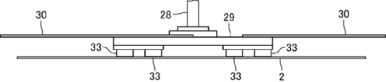
- FIG. 5 is a side view of the panel grip 29 and the expansion member 30 shown in FIG.
- the robot 8 is a so-called three-axis orthogonal robot.
- the robot 8 includes a main body frame 20 formed in a gate shape, a movable frame 21 held by the main body frame 20 so as to be slidable in the left-right direction with respect to the main body frame 20, and the movable frame 21.
- a tray grip portion 24 attached to the movable frame 23.
- the robot 8 includes a drive mechanism that slides the movable frame 21 in the left-right direction, a drive mechanism that slides the movable frame 22 in the front-rear direction, and a drive mechanism that slides the movable frame 23 in the up-down direction.
- the height of the main body frame 20 is higher than the height of the conveyors 4 and 5, and the main body frame 20 is installed across the conveyors 4 and 5 in the left-right direction.
- the movable frame 21 is attached to the upper surface side of the main body frame 20.
- the movable frame 21 is disposed above the tray 3 in a stacked state placed on the conveyors 4 and 5.
- the movable frame 22 is attached to the right side of the movable frame 21.
- the movable frame 23 is attached to the rear end side of the movable frame 22.
- the tray holding part 24 is attached to the lower end of the movable frame 23.
- the tray gripping portion 24 includes a plurality of suction portions that suck the tray 3. When the robot 8 transports the tray 3, the suction unit contacts the upper surface of the tray 3 and vacuum-sucks the tray 3.
- the robot 8 carries in the tray 3 to the tray stages 6 and 7 and carries out the tray 3 placed on the tray stages 6 and 7. That is, the robot 8 carries the tray 3 from the conveyor 4 to the tray stages 6 and 7 and carries the tray 3 from the tray stages 6 and 7 to the conveyor 5. Specifically, the robot 8 transports the stacked trays 3 conveyed to the rear end side of the conveyor 4 one by one to the tray stage 6 or the tray stage 7, and stacks the trays on the conveyor 4. Step 3 Further, the robot 8 conveys one empty tray 3 from the tray stage 6 or the tray stage 7 to the rear end side of the conveyor 5 and stacks the trays 3 on the conveyor 5.
- the robot 9 is a so-called parallel link robot.
- the robot 9 includes a main body 25, three levers 26 connected to the main body 25, three arm parts 27 connected to each of the three levers 26, and three arm parts 27.
- a head unit 28 to be connected, a panel grip 29 attached to the head unit 28, and two expansion members 30 extending to the outer peripheral side of the panel grip 29 are provided.
- the robot 9 is installed so as to hang from the upper surface of the main body frame 13. Further, the main body 25 is disposed above the tray stages 6 and 7 and is disposed behind the main body frame 20 of the robot 8.
- illustration of the expansion member 30 is abbreviate
- the three levers 26 are connected to the main body 25 so as to extend radially at substantially equal angular pitches toward the outer periphery of the main body 25. That is, the three levers 26 are connected to the main body 25 so as to extend radially at a pitch of approximately 120 ° toward the outer periphery of the main body 25. Further, the base end sides of the three levers 26 are rotatably connected to the main body portion 25. A motor 31 with a speed reducer that rotates the lever 26 is disposed at a connecting portion between the main body 25 and the lever 26.
- the robot 9 of this embodiment includes three motors 31 that rotate each of the three levers 26. The output shaft of the motor 31 is fixed to the base end side of the lever 26.
- the proximal end side of the arm portion 27 is connected to the distal end side of the lever 26 so as to be rotatable.
- the arm portion 27 includes two linear arms 32 that are parallel to each other, and the base end sides of the two arms 32 are rotatably connected to the distal end side of the lever 26. ing.
- the head unit 28 is rotatably connected to the distal ends of the three arm portions 27. That is, the head unit 28 is rotatably connected to the distal end side of the six arms 32.
- the three motors 31 are individually driven, so that the head unit 28 is maintained in a predetermined posture in a predetermined area at any position in the vertical direction, the horizontal direction, and the front-rear direction. In this state (specifically, with the panel gripping portion 29 facing downward), the head unit 28 can be moved.
- the panel holding part 29 is formed in a substantially rectangular flat plate shape.
- the panel grip 29 is attached to the lower end of the head unit 28 so that the thickness direction of the panel grip 29 formed in a flat plate shape coincides with the vertical direction.
- a motor 34 is attached to the upper end of the head unit 28 (see FIG. 3).
- the panel grip 29 is connected to the motor 34 and can be rotated with the power of the motor 34 so that the vertical direction is the axis of rotation.
- the panel gripping portion 29 can be rotated around the center of the panel gripping portion 29 formed in a substantially rectangular flat plate shape.
- the motor 34 of this embodiment is a rotation mechanism that rotates the panel gripping portion 29 with the vertical direction as the axis direction of rotation. The position shifted from the center of the panel grip 29 may be the center of rotation of the panel grip 29.
- the panel gripping portion 29 includes a plurality of suction portions 33 (see FIG. 5) that vacuum-suck the liquid crystal panel 2, and sucks and grips the liquid crystal panel 2.
- the suction part 33 is provided on the lower surface side of the panel gripping part 29, and the panel gripping part 29 grips the liquid crystal panel 2 by sucking the upper surface of the liquid crystal panel 2 by the suction part 33. That is, the panel gripping part 29 grips the liquid crystal panel 2 disposed below the panel gripping part 29. Further, the panel gripping part 29 grips the liquid crystal panel 2 so that the thickness direction of the liquid crystal panel 2 matches the vertical direction.
- the expansion member 30 is formed in a substantially rectangular thin plate shape. As shown in FIG. 4, each of the two expansion members 30 is an extension of a diagonal line from each of two corners arranged on one diagonal line of a panel grip portion 29 formed in a substantially rectangular flat plate shape. It is fixed to each of the two corners so as to spread on the line.
- the expansion member 30 is fixed to the panel gripping portion 29 so that the direction of the long side of the panel gripping portion 29 coincides with the direction of the long side of the expansion member 30 when viewed from the top-bottom direction.
- the expansion member 30 is fixed to the upper surface of the panel gripping portion 29, and the liquid crystal panel 2 gripped by the panel gripping portion 29 is disposed below the expansion member 30.
- a polarizing member (polarizing plate or polarizing film) formed in a flat plate shape or a film shape is attached to the lower surface of the expansion member 30.
- the outer shape of the panel gripping portion 29 when viewed from above and below is smaller than the outer shape of the liquid crystal panel 2.
- the liquid crystal panel 2 is gripped by the panel gripping portion 29 so that the center of the liquid crystal panel 2 and the center of the panel gripping portion 29 are substantially coincident when viewed from above and below. Further, the liquid crystal panel 2 is gripped by the panel gripping portion 29 so that the direction of the long side of the liquid crystal panel 2 and the direction of the long side of the panel gripping portion 29 are substantially coincident when viewed from the vertical direction.
- the liquid crystal panel 2 held by the panel holding unit 29 is disposed below the panel holding unit 29 and the expansion member 30. Note that the center of the liquid crystal panel 2 held by the panel holding portion 29 may be shifted from the center of the panel holding portion 29 when viewed from the vertical direction.
- each of the two corner portions 2 b and 2 c is covered with each of the two expansion members 30.
- the expansion member 30 is formed so as to extend to the outer peripheral side of the liquid crystal panel 2 with respect to the corner portions 2 b and 2 c, and the corner portions 2 b and 2 c are completely covered from the upper side by the expansion member 30.
- the corner portions 2b and 2c in the present embodiment are first corner portions.
- the robot 9 carries out the liquid crystal panels 2 one by one from the tray 3 placed on the tray stage 6 or the tray 3 placed on the tray stage 7. Specifically, the robot 9 carries out the liquid crystal panels 2 one by one from the tray 3 until the tray 3 placed on the tray stages 6 and 7 becomes empty. Further, the robot 9 conveys the liquid crystal panel 2 carried out from the tray 3 to a slide stage 48 described later.
- the supply unit 11 includes a camera 41 that reads optically readable data recorded on the liquid crystal panel 2 (see FIG. 2).
- the supply unit 11 includes two cameras 42 that detect the corners 2b and 2c of the liquid crystal panel 2, a robot 44 that conveys the liquid crystal panel 2 after data is read by the camera 41, to the processing device 15, and An ionizer (static removal device) 45 that removes static electricity from the liquid crystal panel 2 that is transported to the processing device 15, and a transport device 46 that transports the liquid crystal panel 2 after data is read by the camera 41 toward the robot 44.
- the camera 42 of this embodiment is a second camera.
- the camera 42 is disposed between the tray stage 6 and the tray stage 7 in the left-right direction. Further, the camera 42 is arranged so that the optical axis direction of the camera 42 coincides with the vertical direction.
- the camera 42 is disposed below the liquid crystal panel 2 held by the panel holding unit 29 and detects the corners 2 b and 2 c of the liquid crystal panel 2 from the lower side of the liquid crystal panel 2. Specifically, each of the two cameras 42 detects the position of each of the two corners 2 b and 2 c from the lower side of the liquid crystal panel 2.
- a polarizing filter is attached to the tip of the lens of the camera 42. The phase of the polarizing filter of the camera 42 and the phase of the polarizing member attached to the lower surface of the expansion member 30 are shifted by 90 °.
- the polarizing member may not be attached to the lower surface of the expansion member 30.
- the lower surface of the expansion member 30 is black.
- the polarizing filter may not be attached to the camera 42.
- the camera 41 is disposed between the tray stage 6 and the tray stage 7 in the left-right direction.
- the camera 41 is arranged on the right side (tray stage 7 side) with respect to the center position between the tray stage 6 and the tray stage 7 in the left-right direction.
- the camera 41 is arranged so that the optical axis direction of the camera 41 coincides with the vertical direction.
- the camera 41 is disposed below the liquid crystal panel 2 held by the panel holding unit 29.
- the camera 41 is arranged on the rear end side of the tray stages 6 and 7. In this embodiment, the camera 41 is disposed slightly behind the rear end surfaces of the tray stages 6 and 7. The camera 41 is disposed behind the camera 42.
- the camera 41 reads data recorded on the liquid crystal panel 2 from the lower side of the liquid crystal panel 2. When the camera 41 reads data, the light emitted from the illumination (not shown) is applied to the liquid crystal panel 2 from below.
- the transfer device 46 includes a slide stage 48 (see FIG. 2) on which the liquid crystal panel 2 is placed, a fixed frame that holds the slide stage 48 so as to be slidable in the left-right direction, and slides relative to the fixed frame. And a drive mechanism that slides the stage 48 in the left-right direction.
- the slide stage 48 includes a plurality of suction units that vacuum-suck the liquid crystal panel 2 placed on the upper surface of the slide stage 48.
- the robot 44 includes a panel holding portion 49 (see FIG. 2) that holds the liquid crystal panel 2 by vacuum suction, a movable frame that holds the panel holding portion 49 so that the liquid crystal panel 2 can slide in the vertical direction, and a horizontal direction.
- a second movable frame that holds the movable frame so as to be slidable, a fixed frame that holds the second movable frame so that sliding in the front-rear direction is possible, and a panel gripper 49 with respect to the movable frame.
- a drive mechanism that slides the movable frame in the left-right direction relative to the second movable frame, and a drive mechanism that slides the second movable frame in the front-rear direction relative to the fixed frame.
- the robot 9 grips the liquid crystal panel 2 in the tray 3 on the tray stages 6 and 7, and performs camera operation. Transport to above 42. Specifically, as shown in FIG. 4, in the vicinity of one corner 2 b of the two corners 2 b and 2 c of the liquid crystal panel 2 directly above one of the two cameras 42. The robot 9 conveys the liquid crystal panel 2 so that the portion is disposed and the portion near the other corner 2c is disposed directly above the other camera 42. When the liquid crystal panel 2 is conveyed above the camera 42, the positions of the two corners 2b and 2c are detected by the two cameras 42 from the lower side.
- the robot 9 adjusts the position of the liquid crystal panel 2 based on the detection result of the positions of the corners 2b and 2c by the camera 42.
- the liquid crystal panel 2 is conveyed from above 42 to above the camera 41. That is, the robot 9 transports the liquid crystal panel 2 from above the camera 42 to above the camera 41 while moving the panel gripping portion 29 based on the detection result of the camera 42 and aligning the liquid crystal panel 2. .
- the robot 9 drives the motors 31 and 34 based on the detection result of the camera 42 to slightly rotate the panel grip portion 29 with the vertical direction as the axis direction of rotation, and to the front and rear, left and right directions.
- the liquid crystal panel 2 is transported from the upper side of the camera 42 to the upper side of the camera 41 while the liquid crystal panel 2 is aligned by moving the panel gripping part 29 to the upper side.
- the camera 41 reads the data on the liquid crystal panel 2.
- the data of the liquid crystal panel 2 read by the camera 41 is linked to the liquid crystal panel 2 from which the data has been read as individual data of the liquid crystal panel 2 from which the data has been read.
- the robot 9 transports the liquid crystal panel 2 to the slide stage 48 and places the liquid crystal panel 2 on the slide stage 48.
- the transport device 46 moves the slide stage 48 and transports the liquid crystal panel 2 to a position where the panel gripping portion 49 of the robot 44 can grip the liquid crystal panel 2.
- the robot 44 grips the liquid crystal panel 2 transported by the transport device 46 by vacuum suction using the panel gripping portion 49, and carries the liquid crystal panel 2 from the slide stage 48 into the processing device 15.
- FIG. 10 is a flowchart for explaining the operation of the robot 9 shown in FIG.
- the robot 9 When reading the data recorded on the liquid crystal panel 2 with the camera 41, the robot 9 conveys the liquid crystal panel 2 above the camera 41 so that the end face of the liquid crystal panel 2 is parallel to the front-rear direction. Specifically, when the data recorded on the liquid crystal panel 2 is read by the camera 41, the robot 9 has front and rear end faces (long sides of the liquid crystal panel 2) of the liquid crystal panel 2 formed in a rectangular shape. The liquid crystal panel 2 is conveyed above the camera 41 so as to be parallel to the direction.
- the one corner portion 2b or the expansion member 30 covering the corner portion 2c is on the left rear side.
- the expansion member 30 (first expansion member) that is disposed and covers the other corner 2c or the corner 2b is disposed on the right front side.
- the end surfaces in the short direction of the tray stages 6 and 7 are parallel to the front-rear direction, and the right end surface of the tray stage 6 (that is, the end surface on the tray stage 7 side) 6a and the tray stage 7 are.
- the left end surface (that is, the end surface on the tray stage 6 side) 7a is parallel to the front-rear direction.
- the left end surface (the end surface on the tray stage 6 side) of the expansion member 30 disposed on the left rear side. ) Is parallel to the front-rear direction
- the right end surface (end surface on the tray stage 7 side, first end surface) of the expansion member 30 arranged on the right front side is parallel to the front-rear direction.
- the left end surface of the expansion member 30 disposed on the left rear side is the left end of the liquid crystal panel 2.
- the right end surface of the expansion member 30 disposed on the left side of the surface and disposed on the right front side is disposed on the right side of the right end surface of the liquid crystal panel 2.
- the end surface in the short direction of the liquid crystal panel 2 is parallel to the front-rear direction, and the right end surface (third end surface) of the liquid crystal panel 2 and the center of the camera 41 are in the same position in the left-right direction.
- the left end surface (second end surface) of the liquid crystal panel 2 is disposed on the right side (tray stage 7 side) of the right end surface 6a of the tray stage 6.
- the end face of the liquid crystal panel 2 in the short direction is parallel to the front-rear direction, and the center of the liquid crystal panel 2 and the center of the camera 41 in the left-right direction are at the same position in the left-right direction.
- the right end surface of the expansion member 30 disposed on the right front side is disposed on the left side (the tray stage 6 side) of the left end surface 7a of the tray stage 7.
- the end face in the short direction of the liquid crystal panel 2 is parallel to the front-rear direction, and the right end face of the liquid crystal panel 2 and the center of the camera 41 are arranged at the same position in the left-right direction, as viewed from above and below.
- the distance L1 between the left end surface of the liquid crystal panel 2 and the right end surface 6a of the tray stage 6 (see FIG. 6A) and the end surface in the short direction of the liquid crystal panel 2 are parallel to the front-rear direction and left and right
- the distance L2 from the left end surface 7a is substantially equal.
- the robot 9 sets the rectangular shape of the liquid crystal panel 2 in the lateral direction so that the end face in the short direction is parallel to the front-rear direction.
- the liquid crystal panel 2 is conveyed upward.
- the robot 9 has one end surface 2 d in the short direction of the liquid crystal panel 2 disposed on the right side, and the short side of the liquid crystal panel 2.
- the liquid crystal panel 2 is conveyed above the camera 42 so that the other end surface 2e in the direction is arranged on the left side (see FIG. 4).
- the end faces (one end face 2d and the other end face 2e) of the liquid crystal panel 2 are parallel to the front-rear direction, and the center of the liquid crystal panel 2 and the center of the camera 41 in the left-right direction are the same in the left-right direction.
- the right end surface of the expansion member 30 disposed on the right front side is disposed on the left side of the left end surface 7 a of the tray stage 7.
- the short side direction center of the liquid crystal panel 2 (the center of the liquid crystal panel 2 in the horizontal direction when the data of the liquid crystal panel 2 is read by the camera 41) is closer to the one end face 2d side.
- the data recording unit 2a is formed in the region 2f of the liquid crystal panel 2 (specifically, when the data recording unit 2a is formed on the lower surface of the region 2f), the data of the liquid crystal panel 2 is transferred to the camera.
- the tray stage 7 is a movement range of the tray gripping portion 24 and the like of the robot 8. Therefore, when the liquid crystal panel 2 or the expansion member 30 and the tray stage 7 overlap with each other in the vertical direction, the robot 8 that performs the operation of transporting the tray 3 to the tray stage 7 interferes with the liquid crystal panel 2 or the expansion member 30. There is a risk.
- the robot 9 detects the corners 2b and 2c with the camera 42 when reading the data of the liquid crystal panel 2 with the camera 41.
- the liquid crystal panel 2 is conveyed above the camera 41 in the same direction as the direction 2.
- the robot 9 reads the data on the liquid crystal panel 2 with the camera 41, and the liquid crystal panel when the corners 2b and 2c are detected with the camera 42.
- the liquid crystal panel 2 is transported above the camera 41 in a direction rotated approximately 180 ° with the vertical direction as the axial direction of rotation from the direction 2 (see FIG. 7B).
- the robot 9 detects the corners 2b and 2c of the liquid crystal panel 2 with the camera 42 and then rotates the panel holding unit 29 by approximately 180 °. After that, the liquid crystal panel 2 is disposed above the camera 41.
- the robot 9 can be used regardless of whether the data recording unit 2a is formed in the region 2f or the data recording unit 2a is formed in the region 2g.
- the liquid crystal panel 2 is transported so that the data recording unit 2a is disposed on the right side (tray stage 7 side) of the center of the liquid crystal panel 2 in the horizontal direction.
- Whether the data recording unit 2a is formed in the area 2f or whether the data recording unit 2a is formed in the area 2g is determined based on the position information of the data recording unit 2a input to the input unit 17. 16 judges. Further, when the robot 9 reads the data of the liquid crystal panel 2 with the camera 41, the direction of the liquid crystal panel 2 when the corners 2 b and 2 c are detected with the camera 42 based on the control command from the control unit 16 is the same. The liquid crystal panel 2 is transported above the camera 41 in the direction of the angle, and the vertical direction is rotated by about 180 ° from the direction of the liquid crystal panel 2 when the corners 2b and 2c are detected by the camera 42. The liquid crystal panel 2 is transported above the camera 41 in the orientation. That is, when the robot 9 reads the data of the liquid crystal panel 2 with the camera 41, the robot 9 transports the liquid crystal panel 2 above the camera 41 based on the position information of the data recording unit 2 a input to the input unit 17.
- the data recording unit 2a is formed in the region 2j (see FIG. 9) of the liquid crystal panel 2 defined by a predetermined range toward the other end surface 2e (specifically, the data recording unit is formed on the lower surface of the region 2j) 2a)
- the expansion member 30 covering the corner 2b and the tray stage 6 may overlap in the vertical direction (See FIG. 9A).
- the expansion member 30 covering the corner 2c in the longitudinal direction of the liquid crystal panel 2, in the range in which the expansion member 30 covering the corner 2c is disposed and in the short direction of the liquid crystal panel 2, the other end surface 2e in the short direction of the liquid crystal panel 2 to the one end surface 2d.
- the data recording unit 2a is formed in the region 2n (see FIG. 9) of the liquid crystal panel 2 defined by the predetermined range toward the side (specifically, the data recording unit 2a is formed on the lower surface of the region 2n)
- the expansion member 30 that covers the corner 2c and the tray stage 6 may overlap in the vertical direction.
- the end face in the short direction of the liquid crystal panel 2 is parallel to the front-rear direction, and the right end face of the liquid crystal panel 2 and the center of the camera 41 are arranged at the same position in the left-right direction.
- the left end surface of the liquid crystal panel 2 is disposed on the right side of the right end surface 6a of the tray stage 6, and therefore the region 2p of the liquid crystal panel 2 excluding the regions 2j and 2n.
- the data recording part 2a is formed (see FIG. 9) (specifically, when the data recording part 2a is formed on the lower surface of the region 2p), the data recording part 2a is read by the camera 41.
- the expansion member 30 and the tray stage 6 do not overlap in the vertical direction (see FIG. 9B).
- the upper part of the tray stage 6 is a moving range of the tray gripping portion 24 of the robot 8 and the like. Therefore, when the expansion member 30 and the tray stage 6 overlap in the vertical direction, the robot 8 that performs the operation of transporting the tray 3 to the tray stage 6 and the expansion member 30 may interfere with each other.
- the operation of the robot 8 is restricted when the data of the liquid crystal panel 2 is read by the camera 41. Specifically, in the case where the data recording unit 2a is formed in the areas 2j and 2n, the data camera of the liquid crystal panel 2 immediately after the movement of the liquid crystal panel 2 from above the camera 42 to above the camera 41 is started. The tray holding portion 24 of the robot 8 does not move until the reading at 41 is finished and the liquid crystal panel 2 is placed on the slide stage 48. On the other hand, when the data recording unit 2a is formed in the region 2p, the operation of the robot 8 is not restricted.
- Whether the data recording unit 2a is formed in the areas 2j and 2n is determined by the control unit 16 based on the position information of the data recording unit 2a input to the input unit 17.
- the control unit 16 regulates the operation of the robot 8 when the data recorded on the liquid crystal panel 2 is read by the camera 41.
- the areas 2j and 2n of the present embodiment are the expansion member 30 and the tray stage 6 of the robot 9 in a state where the liquid crystal panel 2 is disposed above the camera 41 when the data recorded on the liquid crystal panel 2 is read by the camera 41. Is an interference area that is an area of the liquid crystal panel 2 in which the data recording portion 2a is formed.
- the operations of the robot 9 and the like are summarized as shown in the flowchart of FIG. That is, when predetermined information such as the size information of the liquid crystal panel 2 and the position information of the data recording unit 2 a is input to the input unit 17 and the automatic operation is started, the robot 9 performs the tray 3 on the tray stages 6 and 7.
- the liquid crystal panel 2 is gripped (step S1) and conveyed above the camera 42 (step S2). Thereafter, when the corners 2b and 2c of the liquid crystal panel 2 are detected by the camera 42, the robot 9 starts moving the liquid crystal panel 2 from above the camera 42 to above the camera 41 (step S3).
- step S4 determines whether or not the data recording unit 2a is formed in the areas 2j and 2n based on the position information of the data recording unit 2a input to the input unit 17 (step S4). .
- step S4 when the data recording unit 2a is formed in the areas 2j and 2n, the control unit 16 regulates the operation of the robot 8 (step S5) and then the data recording unit input to the input unit 17 Based on the position information of 2a, it is determined whether the data recording unit 2a is formed in the region 2f or whether the data recording unit 2a is formed in the region 2g (step S6). On the other hand, if the data recording unit 2a is formed in the region 2p in step S4, the process proceeds to step S6 as it is.
- step S6 when the data recording unit 2a is formed in the region 2f, the robot 9 has the same orientation as that of the liquid crystal panel 2 when the corners 2b and 2c are detected by the camera 42. Is conveyed above the camera 41 (step S7).
- step S7 when the data recording unit 2a is formed in the region 2g in step S6, the robot 9 rotates in the vertical direction from the direction of the liquid crystal panel 2 when the corners 2b and 2c are detected by the camera 42.
- the liquid crystal panel 2 is conveyed above the camera 41 in a direction rotated approximately 180 ° as the axial direction of the camera (step S8).
- steps S7 and S8 when the liquid crystal panel 2 is transported above the camera 41, the position of the liquid crystal panel 2 is aligned based on the detection results of the positions of the corners 2b and 2c by the camera 42, The liquid crystal panel 2 is conveyed.
- the camera 41 reads the data recorded on the liquid crystal panel 2 (step S9).
- the robot 9 conveys the liquid crystal panel 2 to the slide stage 48 (step S10).
- the robot 9 places the liquid crystal panel 2 on the slide stage 48 (step S11), returns to step S1, and holds another liquid crystal panel 2 in the tray 3 on the tray stages 6 and 7.
- the data recording unit 2a is formed in the region 2f of the liquid crystal panel 2 and the data recording unit 2a is formed in the region 2g of the liquid crystal panel 2. Even when the robot 9 reads the data of the liquid crystal panel 2 with the camera 41, the robot 9 transports the liquid crystal panel 2 so that the data recording unit 2a is arranged on the right side of the center of the liquid crystal panel 2 in the horizontal direction. is doing.
- the robot 9 when the robot 9 reads the data of the liquid crystal panel 2 with the camera 41, the robot 9 is on the right side of the center of the liquid crystal panel 2 in the horizontal direction based on the position information of the data recording unit 2 a input to the input unit 17.
- the liquid crystal panel 2 is transported above the camera 41 so that the data recording unit 2a is disposed on the camera 41. That is, in this embodiment, the operation of the robot 9 when reading the data of the liquid crystal panel 2 with the camera 41 is set by inputting the position information of the data recording unit 2 a to the input unit 17. Therefore, in this embodiment, it is possible to easily set the operation of the robot 9 when reading the data of the liquid crystal panel 2 with the camera 41.
- each of the two corner portions 2 b and 2 c is covered with each of the two expansion members 30, and
- the camera 42 shows the lower surface of the expansion member 30 together with the corners 2b and 2c.
- the phase of the polarizing member attached to the lower surface of the expansion member 30 and the phase of the polarizing filter of the camera 42 are shifted by 90 °, and the lower surface of the expansion member 30 reflected in the camera 42 is black.
- the corner portions 2 b and 2 c of the liquid crystal panel 2 reflected on the camera 42 and the expansion member 30.
- the camera 42 can accurately detect the corners 2 b and 2 c of the liquid crystal panel 2. Therefore, in this embodiment, it is possible to accurately detect the corners 2b and 2c of the liquid crystal panel 2 and to accurately align the liquid crystal panel 2 while reducing the size of the panel grip portion 29.
- the upper surface of the reflecting plate that reflects light toward the liquid crystal panel 2 is white. If the lower surface of the expansion member 30 is black, the contrast between the corners 2b and 2c of the liquid crystal panel 2 reflected on the camera 42 and the lower surface of the expansion member 30 can be increased. Therefore, even in this case, the corners 2b and 2c of the liquid crystal panel 2 can be accurately detected by the camera 42 even if the outer shape of the panel gripping portion 29 when viewed from above and below is smaller than the outer shape of the liquid crystal panel 2. Can be detected.
- the camera 41 is disposed on the rear end side of the tray stages 6 and 7.
- the liquid crystal panel 2 when the data of the liquid crystal panel 2 is read by the camera 41, when the liquid crystal panel 2 is disposed above the camera 41, one expansion member 30 is disposed on the left rear side, and the other The expansion member 30 is disposed on the right front side. Therefore, in this embodiment, the regions 2j and 2n can be narrowed in the longitudinal direction of the liquid crystal panel 2.
- the range of the regions 2j and 2n in the longitudinal direction of the liquid crystal panel 2 is the entire region in the longitudinal direction of the liquid crystal panel 2.
- the range in which the expansion member 30 covering 2b is arranged is the range of the region 2j in the longitudinal direction of the liquid crystal panel 2
- the range in which the expansion member 30 covering the corner 2c is arranged in the longitudinal direction of the liquid crystal panel 2 is 2 is the range of the region 2n in the longitudinal direction. Therefore, in this embodiment, the regions 2j and 2n can be narrowed in the longitudinal direction of the liquid crystal panel 2.
- the end face in the short direction of the liquid crystal panel 2 is parallel to the front-rear direction, and the right end face of the liquid crystal panel 2 and the center of the camera 41 are arranged at the same position in the left-right direction, as viewed from above and below.
- the distance L1 between the left end face of the liquid crystal panel 2 and the right end face 6a of the tray stage 6, the end face in the short direction of the liquid crystal panel 2 is parallel to the front-rear direction, and the center of the liquid crystal panel 2 in the left-right direction.
- the camera 41 of the data on the liquid crystal panel 2 immediately after the liquid crystal panel 2 starts to move from above the camera 42 to above the camera 41.
- the tray grip 24 of the robot 8 does not move. Therefore, in this embodiment, even when the data recording unit 2a is formed in the areas 2j and 2n, when the data of the liquid crystal panel 2 is read by the camera 41, the expansion member 30 disposed on the left rear side and the robot 8 Interference can be prevented.
- the end surface in the short direction of the liquid crystal panel 2 is parallel to the front-rear direction, and the right end surface of the liquid crystal panel 2 and the center of the camera 41 are disposed at the same position in the left-right direction (FIG. 6 (The left end surface of the liquid crystal panel 2 may be disposed on the left side of the right end surface 6a of the tray stage 6 when viewed from above and below in the state shown in A). In this case, when the data recorded in the data recording unit 2a is read by the camera 41, the left end portion of the liquid crystal panel 2 and the tray stage 6 may overlap in the vertical direction.
- the control unit 16 determines whether or not the data recording unit 2a is formed in the interference area based on the position information of the data recording unit 2a and the size information of the liquid crystal panel 2 input to the input unit 17. Determine whether.
- the left end surface of the expansion member 30 disposed on the left rear side is disposed on the right side of the right end surface 6a of the tray stage 6 when viewed from the top and bottom in the state shown in FIG. Also good.
- the interference areas 2j and 2n are eliminated, there is no need to regulate the operation of the robot 8 when the camera 41 reads the data recorded in the data recording unit 2a.
- the end face in the short direction of the liquid crystal panel 2 is parallel to the front-rear direction, and the center of the liquid crystal panel 2 and the center of the camera 41 in the left-right direction are arranged at the same position in the left-right direction (see FIG. 6B), the right end surface of the expansion member 30 disposed on the right front side may be disposed on the right side of the left end surface 7a of the tray stage 7 when viewed from above and below.
- the expansion member 30 arranged on the right front side and the tray stage 7 may overlap in the vertical direction.
- the expansion member 30 and the tray stage 7 disposed on the right front side are vertically moved with the liquid crystal panel 2 disposed above the camera 41.
- the area of the liquid crystal panel 2 in which the data recording unit 2a is formed becomes an interference area.
- the control unit 16 determines whether or not the data recording unit 2a is formed in the interference area based on the position information of the data recording unit 2a input to the input unit 17.
- the right end surface of the liquid crystal panel 2 may be disposed on the right side of the left end surface 7a of the tray stage 7 when viewed from above and below in the state shown in FIG.
- the right end portion of the liquid crystal panel 2 and the tray stage 7 may overlap in the vertical direction.
- the control unit 16 determines whether or not the data recording unit 2a is formed in the interference area based on the position information of the data recording unit 2a and the size information of the liquid crystal panel 2 input to the input unit 17. Determine whether.
- the supply unit 11 may not include the camera 42 that detects the corners 2b and 2c of the liquid crystal panel 2.
- the robot 9 may not include the expansion member 30.
- the left end surface of the liquid crystal panel 2 is disposed on the right side of the right end surface 6 a of the tray stage 6 when viewed from above and below in the state shown in FIG. 6B
- the right end surface of the liquid crystal panel 2 is preferably arranged on the left side of the left end surface 7a of the tray stage 7 when viewed from above and below in the state shown in FIG.
- there is no interference area there is no need to regulate the operation of the robot 8 when the camera 41 reads the data recorded in the data recording unit 2a.
- the robot 9 has the tray stage 6 such that the end face in the short direction of the liquid crystal panel 2 formed in a rectangular shape is parallel to the front-rear direction. 7. Hold the liquid crystal panel 2 in the tray 3 on the upper side. Further, the robot 9 transports the liquid crystal panel 2 above the camera 41 in the same direction as that of the liquid crystal panel 2 when the robot 9 grips the liquid crystal panel 2 based on a control command from the control unit 16. The robot 9 transports the liquid crystal panel 2 to the upper side of the camera 41 in a direction rotated about 180 ° with the vertical direction as the axis direction of rotation from the direction of the liquid crystal panel 2 when the robot 9 grips the liquid crystal panel 2.
- the robot 9 when the camera 2 detects the corners 2b and 2c of the liquid crystal panel 2, the robot 9 has an end face in the longitudinal direction of the liquid crystal panel 2 formed in a rectangular shape (the short side of the liquid crystal panel 2). ) May be transported above the camera 42 so that it is parallel to the front-rear direction.
- the robot 9 sets the vertical direction from the direction of the liquid crystal panel 2 when the corners 2b and 2c are detected by the camera 42 according to the position where the data recording unit 2a is formed, as the axis direction of rotation.
- the liquid crystal panel 2 is conveyed above the camera 41 in a direction rotated approximately 90 ° in one direction or the other direction.
- the transport system 1 may be a system for transporting the liquid crystal panel 2 discharged from the processing device 15, or transports and processes the liquid crystal panel 2 supplied to the processing device 15.
- a system for transporting the liquid crystal panel 2 discharged from the device 15 may be used.
- the robot 9 transfers the liquid crystal panel 2 discharged from the processing device 15 to the tray 3 placed on the tray stages 6 and 7. Carry in. In this case, the data of the liquid crystal panel 2 is read by the camera 41 before the liquid crystal panel 2 is carried into the tray 3. Further, when the transport system 1 transports the liquid crystal panel 2 supplied to the processing device 15 and transports the liquid crystal panel 2 discharged from the processing device 15, the robot 9 moves the trays on the tray stages 6 and 7. 3 and the liquid crystal panel 2 discharged from the processing device 15 is loaded into the tray 3 on the tray stages 6 and 7.
- the robot 8 may only carry the tray 3 into the tray stages 6 and 7 or may carry out only the tray 3 placed on the tray stages 6 and 7.
- the camera 41 may be disposed on the front side of the rear end surfaces of the tray stages 6 and 7. Furthermore, in the embodiment described above, the camera 41 may be disposed at the center position between the tray stage 6 and the tray stage 7 in the left-right direction.
- the supply unit 11 may include one camera 42.
- the plurality of trays 3 may be placed on the tray stages 6 and 7 so as not to overlap each other.
- the robot 9 is a parallel link robot, but the robot 9 may be a robot such as a horizontal articulated robot or a vertical articulated robot.
- the robot 8 is a three-axis orthogonal robot, but the robot 8 may be a robot such as a horizontal articulated robot.
- the display panel transported by the transport system 1 is the liquid crystal panel 2, but the display panel transported by the transport system 1 may be a display panel other than the liquid crystal panel 2.
- the display panel transported by the transport system 1 may be an organic EL panel.
- Transport system Liquid crystal panel (display panel) 2a Data recording portion 2b, 2c Corner portion (first corner portion) 2d One end face (end face of display panel) 2e The other end face (end face of the display panel) 2j, 2n area (interference area) 3 tray 6 tray stage (first tray stage) 6a Right end surface (end surface of the first tray stage on the second tray stage side) 7 Tray stage (second tray stage) 7a Left end surface (end surface of the second tray stage on the first tray stage side) 8 Robot (second robot) DESCRIPTION OF SYMBOLS 9 Robot 15 Processing apparatus 16 Control part 17 Input part 29 Panel holding part 30 Expansion member 34 Motor (rotation mechanism) 41 camera 42 camera (second camera) X 2nd direction X1 4th direction X2 3rd direction Y 1st direction
Abstract
搬送システムにおいて、光学的に読取可能なデータが表示パネルの様々な位置に記録されていても、表示パネルのデータをカメラで読み取る際の、2個のトレイステージが並んでいる方向におけるロボットのパネル把持部の移動範囲を狭めることが可能な搬送システムを提供する。この搬送システムでは、表示パネル2に記録された光学的に読取可能なデータをカメラ41で読み取るときに、ロボットは、表示パネル2の端面2d、2eがX方向と平行になるようにカメラ41の上方に表示パネル2を搬送するとともに、表示パネル2のY方向の中心よりもトレイステージ7側に表示パネル2のデータ記録部2aが配置されるように表示パネル2を搬送する。
Description
本発明は、液晶パネル等の表示パネルを搬送する搬送システムに関する。
従来、携帯機器等で使用される液晶表示装置の組立ラインに組み込まれる搬送装置が知られている(たとえば、特許文献1参照)。特許文献1に記載の搬送装置は、5個の搬送ユニットを備えており、各搬送ユニットには、液晶表示装置の組立工程における各種の組立加工処理が割り当てられている。また、この搬送装置は、トレイに収容された液晶パネルを搬送ユニットに供給する自動ローダーを備えている(特許文献1の図19参照)。自動ローダーは、たとえば、トレイに収容された液晶パネルを搬送ユニットに搬送するロボットを備えている。なお、特許文献1に記載の搬送装置では、液晶パネルの表示領域から外れた箇所に記録された光学的に読取可能なデータを読み取るカメラが設置されていることがある。
特許文献1に記載の搬送装置では、空になったトレイを、液晶パネルが収容されたトレイに交換するときに、液晶パネルを供給することができず、サイクルタイムが長くなる。そこで、本願発明者は、サイクルタイムを短縮するため、トレイが載置されるトレイステージを2個、設置することを検討している。2個のトレイステージが設置されていれば、一方のトレイステージ上のトレイの交換時にも、他方のトレイステージ上のトレイから液晶パネルを供給することが可能になる。
また、本願発明者は、トレイから搬出される液晶パネルのデータを読み取るカメラの設置を検討している。具体的には、2個のトレイステージのどちらのトレイステージ上のトレイから液晶パネルが搬出されても、カメラまでの搬送時間が短縮されるように、2個のトレイステージが並んでいる方向において、2個のトレイステージの間にカメラを設置することを検討している。この場合、トレイから搬出される液晶パネルは、ロボットのパネル把持部に把持されてカメラまで搬送される。ここで、液晶パネルに対するデータの記録位置は、液晶パネルの仕様によって変わることがある。液晶パネルの仕様に応じて液晶パネルの様々な位置に記録されるデータを1箇所に固定されたカメラによって読み取る場合、カメラでデータを読み取る際のロボットのパネル把持部の移動範囲が広くなるおそれがある。
2個のトレイステージが並んでいる方向において、カメラでデータを読み取る際のパネル把持部の移動範囲が広くなると、たとえば、トレイステージに対してトレイを搬送する搬送機構が動作しているときや、トレイに対して液晶パネルを搬送するロボットが動作しているときに、パネル把持部が把持している液晶パネルと搬送機構とが干渉するおそれや、パネル把持部と搬送機構とが干渉するおそれが高くなる。また、これらの干渉のおそれが高くなると、カメラでデータを読み取る際に、搬送機構の動作が規制されたり、ロボットの動作が規制されたりする場面が多くなって、サイクルタイムが長くなる。
そこで、本発明の課題は、液晶パネル等の表示パネルを収容可能なトレイが載置される2個のトレイステージと、表示パネルに記録された光学的に読取可能なデータを読み取るカメラと、カメラに向かって表示パネルを搬送するロボットとを備える搬送システムにおいて、光学的に読取可能なデータが表示パネルの様々な位置に記録されていても、表示パネルに記録されたデータをカメラで読み取る際の、2個のトレイステージが並んでいる方向におけるロボットのパネル把持部の移動範囲を狭めることが可能な搬送システムを提供することにある。
上記の課題を解決するため、本発明の搬送システムは、所定の処理装置に供給される表示パネルの搬送および所定の処理装置から排出される表示パネルの搬送の少なくともいずれか一方を行う搬送システムであって、矩形状に形成された表示パネルを収容可能なトレイが載置される第1トレイステージおよび第2トレイステージと、第1トレイステージに載置されたトレイおよび第2トレイステージに載置されたトレイからの表示パネルの搬出と、第1トレイステージに載置されたトレイおよび第2トレイステージに載置されたトレイへの表示パネルの搬入との少なくともいずれか一方を行うロボットと、表示パネルに記録された光学的に読取可能なデータを読み取るカメラとを備え、表示パネルには、データが記録されたデータ記録部が形成され、ロボットは、表示パネルの厚さ方向と上下方向とが一致するように表示パネルを把持するパネル把持部と、上下方向を回動の軸方向としてパネル把持部を回動させる回動機構とを備え、上下方向に直交する所定の方向を第1方向とし、上下方向と第1方向とに直交する方向を第2方向とすると、第1トレイステージと第2トレイステージとは、第1方向において所定の間隔をあけた状態で隣り合うように配置され、カメラは、第1方向において第1トレイステージと第2トレイステージとの間に配置されるとともに、カメラの光軸方向と上下方向とが一致するように配置され、表示パネルに記録されたデータをカメラで読み取るときに、ロボットは、表示パネルの端面が第2方向と平行になるようにカメラの上方に表示パネルを搬送するとともに、表示パネルの第1方向の中心よりも第2トレイステージ側にデータ記録部が配置されるように表示パネルを搬送することを特徴とする。
本発明の搬送システムでは、ロボットは、表示パネルの厚さ方向と上下方向とが一致するように表示パネルを把持するパネル把持部と、上下方向を回動の軸方向としてパネル把持部を回動させる回動機構とを備えている。また、本発明では、表示パネルに記録された光学的に読取可能なデータをカメラで読み取るときに、ロボットは、表示パネルの端面が第2方向と平行になるようにカメラの上方に表示パネルを搬送するとともに、表示パネルの第1方向の中心よりも第2トレイステージ側に表示パネルのデータ記録部が配置されるように表示パネルを搬送している。すなわち、本発明では、表示パネルに記録された光学的に読取可能なデータをカメラで読み取るときに、ロボットは、パネル把持部を回動させる回動機構を用いて、表示パネルの第1方向の中心よりも第2トレイステージ側に表示パネルのデータ記録部が配置されるように表示パネルを搬送している。
そのため、本発明では、光学的に読取可能なデータが表示パネルの様々な位置に記録されていても、表示パネルに記録された光学的に読取可能なデータをカメラで読み取るときに、パネル把持部に把持された表示パネルの第1方向の中心がカメラよりも第2トレイステージ側に移動することはない。すなわち、本発明では、光学的に読取可能なデータが表示パネルの様々な位置に記録されていても、表示パネルに記録された光学的に読取可能なデータをカメラで読み取るときに、パネル把持部の、表示パネルの第1方向の中心を把持する部分がカメラよりも第2トレイステージ側に移動することはない。したがって、本発明では、光学的に読取可能なデータが表示パネルの様々な位置に記録されていても、表示パネルに記録されたデータをカメラで読み取る際の、第1トレイステージと第2トレイステージとが並んでいる方向(第1方向)におけるパネル把持部の移動範囲を狭めることが可能になる。
本発明において、搬送システムを制御する制御部は、表示パネルのどの位置にデータ記録部が形成されているのかを示す情報である位置情報が入力される入力部を備え、ロボットは、表示パネルに記録されたデータをカメラで読み取るときに、入力部に入力された位置情報に基づいてカメラの上方に表示パネルを搬送することが好ましい。このように構成すると、データ記録部の位置情報を入力部に入力することで、表示パネルに記録されたデータをカメラで読み取る際のロボットの動作を設定することが可能になる。したがって、表示パネルに記録されたデータをカメラで読み取る際のロボットの動作を容易に設定することが可能になる。
本発明において、第2方向の一方側を第3方向側とし、第3方向側の反対側を第4方向側とし、矩形状に形成される表示パネルの一方の対角線上に配置される2個の角部のそれぞれを第1角部とすると、たとえば、搬送システムは、表示パネルの下側から第1角部を検知する第2カメラを備え、ロボットは、パネル把持部の外周側へ広がる2個の拡張部材を備え、パネル把持部は、パネル把持部および拡張部材の下側に配置される表示パネルを把持し、上下方向から見たときのパネル把持部の外形は、表示パネルの外形よりも小さくなっており、パネル把持部に把持されている表示パネルを上側から見ると、2個の第1角部のそれぞれは、2個の拡張部材のそれぞれに覆われており、カメラは、第1トレイステージおよび第2トレイステージの第3方向端側に配置され、表示パネルに記録されたデータをカメラで読み取るときにカメラの上方に表示パネルが配置されている状態では、2個の第1角部のうちの一方の第1角部は、第1トレイステージ側かつ第3方向側に配置され、他方の第1角部は、第2トレイステージ側かつ第4方向側に配置されている。
この場合には、パネル把持部に把持されている表示パネルを上側から見ると、表示パネルの2個の第1角部のそれぞれが、パネル把持部の外周側へ広がる2個の拡張部材のそれぞれに覆われているため、上下方向から見たときのパネル把持部の外形が表示パネルの外形より小さくなっていても、第2カメラに写る表示パネルの第1角部と拡張部材の下面とのコントラストを高めることが可能になり、その結果、第2カメラによって表示パネルの第1角部を正確に検知することが可能になる。したがって、パネル把持部を小型化しつつ、表示パネルの角部を正確に検知することが可能になる。
また、この場合には、カメラは、第1トレイステージおよび第2トレイステージの第3方向端側に配置されている。また、第1トレイステージ側に配置される第1角部は第3方向側に配置されており、この第1角部を覆う拡張部材が第3方向側に配置されている。そのため、表示パネルに記録されたデータをカメラで読み取る際に、第1トレイステージにトレイを搬送する搬送機構と、第1トレイステージ側に配置される第1角部を覆う拡張部材とが干渉するパネル把持部の動作範囲を狭めることが可能になる。
本発明において、第1トレイステージの、第2トレイステージ側の端面、および、第2トレイステージの、第1トレイステージ側の端面は、第2方向と平行になっており、表示パネルに記録されたデータをカメラで読み取るときにカメラの上方に表示パネルが配置されている状態で第2トレイステージ側かつ第4方向側に配置される第1角部を覆う拡張部材を第1拡張部材とすると、表示パネルに記録されたデータをカメラで読み取るときにカメラの上方に表示パネルが配置されている状態では、第1拡張部材の第2トレイステージ側の端面である第1端面は、第2方向と平行になっており、表示パネルに記録されたデータをカメラで読み取るときに第2方向と平行に配置される表示パネルの端面であって第1トレイステージ側に配置される端面を第2端面とし、表示パネルの、第2端面の反対側の端面を第3端面とすると、第2端面および第3端面が第2方向と平行になるとともに第3端面とカメラの中心とが第1方向において同じ位置に配置されている状態で上下方向から見たときに、第2端面は、第1トレイステージの第2トレイステージ側の端面よりも第2トレイステージ側に配置され、第2端面および第3端面が第2方向と平行になるとともに第1方向における表示パネルの中心とカメラの中心とが第1方向において同じ位置に配置されている状態で上下方向から見たときに、第1端面は、第2トレイステージの第1トレイステージ側の端面よりも第1トレイステージ側に配置され、第2端面および第3端面が第2方向と平行になるとともに第3端面とカメラの中心とが第1方向において同じ位置に配置されている状態で上下方向から見たときの、第1トレイステージの第2トレイステージ側の端面と第2端面との距離と、第2端面および第3端面が第2方向と平行になるとともに第1方向における表示パネルの中心とカメラの中心とが第1方向において同じ位置に配置されている状態で上下方向から見たときの、第2トレイステージの第1トレイステージ側の端面と第1端面との距離とが略等しくなっていることが好ましい。
このように構成すると、第1方向における第1トレイステージと第2トレイステージとの間隔を狭めつつ、表示パネルに記録されたデータをカメラで読み取る際に、パネル把持部に把持される表示パネルと、第1トレイステージにトレイを搬送する搬送機構との干渉を防止することが可能になるとともに、パネル把持部に把持される表示パネルおよび第1拡張部材と、第2トレイステージにトレイを搬送する搬送機構との干渉を防止することが可能になる。
本発明において、第1トレイステージの、第2トレイステージ側の端面、および、第2トレイステージの、第1トレイステージ側の端面は、第2方向と平行になっており、表示パネルに記録されたデータをカメラで読み取るときに第2方向と平行に配置される表示パネルの端面であって第1トレイステージ側に配置される端面を第2端面とし、表示パネルの、第2端面の反対側の端面を第3端面とすると、第2端面および第3端面が第2方向と平行になるとともに第3端面とカメラの中心とが第1方向において同じ位置に配置されている状態で上下方向から見たときに、第2端面は、第1トレイステージの第2トレイステージ側の端面よりも第2トレイステージ側に配置され、第2端面および第3端面が第2方向と平行になるとともに第1方向における表示パネルの中心とカメラの中心とが第1方向において同じ位置に配置されている状態で上下方向から見たときに、第3端面は、第2トレイステージの第1トレイステージ側の端面よりも第1トレイステージ側に配置され、第2端面および第3端面が第2方向と平行になるとともに第3端面とカメラの中心とが第1方向において同じ位置に配置されている状態で上下方向から見たときの、第1トレイステージの第2トレイステージ側の端面と第2端面との距離と、第2端面および第3端面が第2方向と平行になるとともに第1方向における表示パネルの中心とカメラの中心とが第1方向において同じ位置に配置されている状態で上下方向から見たときの、第2トレイステージの第1トレイステージ側の端面と第3端面との距離とが略等しくなっていることが好ましい。
このように構成すると、第1方向における第1トレイステージと第2トレイステージとの間隔を狭めつつ、表示パネルに記録されたデータをカメラで読み取る際に、パネル把持部に把持される表示パネルと、第1トレイステージにトレイを搬送する搬送機構との干渉を防止することが可能になるとともに、パネル把持部に把持される表示パネルと、第2トレイステージにトレイを搬送する搬送機構との干渉を防止することが可能になる。
本発明において、搬送システムは、第1トレイステージに載置されたトレイの搬出および第2トレイステージに載置されたトレイの搬出と、第1トレイステージへのトレイの搬入および第2トレイステージへのトレイの搬入との少なくともいずれか一方を行う第2ロボットを備え、搬送システムを制御する制御部は、表示パネルのどの位置にデータ記録部が形成されているのかを示す情報である位置情報および表示パネルの大きさを示す情報であるサイズ情報が入力される入力部を備え、表示パネルに記録されたデータをカメラで読み取るときにカメラの上方に表示パネルが配置されている状態で、パネル把持部に把持される表示パネルおよびロボットの少なくともいずれか一方と、第1トレイステージまたは第2トレイステージとが上下方向で重なる場合に、データ記録部が形成されている表示パネルの領域を干渉領域とすると、制御部は、入力部に入力された少なくとも位置情報に基づいて、データ記録部が干渉領域に形成されているのか否かを判断し、データ記録部が干渉領域に形成されている場合、表示パネルに記録されたデータをカメラで読み取るときに、第2ロボットの動作を規制することが好ましい。
このように構成すると、データ記録部が干渉領域に形成されていても、表示パネルに記録されたデータをカメラで読み取る際に、パネル把持部に把持される表示パネルおよびロボットと、第2ロボットとの干渉を防止することが可能になる。
以上のように、本発明では、液晶パネル等の表示パネルを収容可能なトレイが載置される2個のトレイステージと、表示パネルに記録された光学的に読取可能なデータを読み取るカメラと、カメラに向かって表示パネルを搬送するロボットとを備える搬送システムにおいて、光学的に読取可能なデータが表示パネルの様々な位置に記録されていても、表示パネルに記録されたデータをカメラで読み取る際の、2個のトレイステージが並んでいる方向におけるロボットのパネル把持部の移動範囲を狭めることが可能になる。
以下、図面を参照しながら、本発明の実施の形態を説明する。
(搬送システムの全体構成)
図1は、本発明の実施の形態にかかる搬送システム1の側面図である。図2は、図1のE-E方向から搬送システム1を説明するための図である。
図1は、本発明の実施の形態にかかる搬送システム1の側面図である。図2は、図1のE-E方向から搬送システム1を説明するための図である。
本形態の搬送システム1は、携帯機器等で使用される中型の液晶ディスプレイの製造ラインに組み込まれて使用される。この搬送システム1は、表示パネルである液晶パネル2を搬送して、液晶パネル2に対して所定の処理を行う処理装置15(図2参照)に液晶パネル2を供給する。すなわち、搬送システム1は、処理装置15に供給される液晶パネル2を搬送する。また、搬送システム1は、中型の液晶パネル2(たとえば、9~15インチの液晶パネル)を搬送する。なお、搬送システム1で搬送される液晶パネル2は、小型の液晶パネル(たとえば、4インチの液晶パネル)であっても良い。
液晶パネル2は、矩形状に形成されている。具体的には、液晶パネル2は、長方形の平板状に形成されている。液晶パネル2の、表示領域から外れた箇所には、液晶パネル2の検査データ等のデータが記録されている。具体的には、液晶パネル2の、表示領域から外れた箇所に、検査データ等のデータが二次元コードや一次元コードとして記録されている。すなわち、液晶パネル2の、表示領域から外れた箇所には、光学的に読取可能なデータが記録されており、液晶パネル2には、光学的に読取可能なデータが記録されたデータ記録部2a(図4、図7参照)が形成されている。データ記録部2aは、液晶パネル2の仕様に応じて液晶パネル2の様々な位置に形成されている。
なお、本形態の搬送システム1で搬送される液晶パネル2には、偏光板(偏光フィルム)が貼り付けられていても良いし、偏光板が貼り付けられていなくても良い。また、液晶パネル2には、FPCやチップが実装されていても良いし、FPCやチップが実装されていなくても良い。
搬送システム1は、液晶パネル2を収容可能なトレイ3を搬送する2個のコンベヤ4、5を備えている。コンベヤ4、5は、複数段に積み重なったトレイ3(すなわち、段積みされたトレイ3)を水平方向へ直線的に搬送する。以下の説明では、コンベヤ4、5によるトレイ3の搬送方向(図1等のX方向)を「前後方向」とし、上下方向(鉛直方向)と前後方向とに直交する方向(図1等のY方向)を「左右方向」とする。また、前後方向の一方側(図1等のX1方向側)を「前」側とし、その反対側(図1等のX2方向側)を「後ろ」側とし、左右方向の一方側(図2等のY1方向側)を「右」側とし、その反対側(図2等のY2方向側)を「左」側とする。
本形態では、搬送システム1の後ろ側に処理装置15が配置されている。また、本形態の左右方向(Y方向)は、上下方向に直交する所定の方向である第1方向となっており、前後方向は、第1方向である左右方向と上下方向とに直交する第2方向となっている。また、本形態では、後ろ側(X2方向側)は、第2方向の一方側である第3方向側となっており、前側(X1方向側)は、第3方向側の反対側である第4方向側となっている。
また、搬送システム1は、トレイ3が載置される2個のトレイステージ6、7と、コンベヤ4、5とトレイステージ6、7との間でトレイ3を搬送するロボット8と、トレイステージ6、7に載置されたトレイ3から液晶パネル2を搬出するロボット9と、ロボット9から液晶パネル2を受け取って処理装置15に供給する供給ユニット11とを備えている。トレイステージ6、7は、コンベヤ4、5よりも後ろ側に配置されている。供給ユニット11は、トレイステージ6、7よりも後ろ側に配置されている。本形態のトレイステージ6は、第1トレイステージであり、トレイステージ7は、第2トレイステージである。また、ロボット8は、第2ロボットである。
また、搬送システム1は、コンベヤ4、5とトレイステージ6、7とロボット8と供給ユニット11とが設置される本体フレーム12と、ロボット9が設置される本体フレーム13とを備えている。本体フレーム12の上面は、上下方向に直交する平面状に形成されており、本体フレーム12の上面に、コンベヤ4、5とトレイステージ6、7とロボット8と供給ユニット11とが設置されている。本体フレーム13は、略門型に形成された門型フレームであり、左右方向で本体フレーム12の後端側部分を跨ぐように設置されている。ロボット9は、本体フレーム13の上面部に設置されている。
コンベヤ4、5は、複数のローラを備えるローラコンベヤである。コンベヤ4とコンベヤ5とは、左右方向で隣接配置されている。コンベヤ4は、段積みされたトレイ3を後ろ側へ向かって搬送し、コンベヤ5は、段積みされたトレイ3を前側に向かって搬送する。コンベヤ4で搬送されるトレイ3には、液晶パネル2が収容されている。一方、コンベヤ5で搬送されるトレイ3には、液晶パネル2は収容されておらず、コンベヤ5で搬送されるトレイ3は空トレイとなっている。
コンベヤ4の前端側には、仮置き用の棚(図示省略)から作業者によって運ばれてきた段積み状態のトレイ3が載置される。コンベヤ4の前端側に載置された段積み状態のトレイ3は、後ろ側へ搬送され、コンベヤ4の後端側まで搬送された段積み状態のトレイ3は、後述のようにロボット8によって段ばらしされる。また、コンベヤ5の後端側には、後述のようにロボット8によって空のトレイ3が段積みされる。所定の段数までトレイ3が段積みされると、段積み状態のトレイ3は、前側に搬送される。コンベヤ5の前端側まで搬送された段積み状態のトレイ3は、作業者によって空トレイ用の棚まで運ばれる。
トレイステージ6、7は、長方形の平板状に形成されている。トレイステージ6とトレイステージ7とは、同形状に形成されている。トレイステージ6、7は、本体フレーム12の上面から立ち上がる架台の上端に固定されている(図1参照)。トレイステージ6とトレイステージ7とは、左右方向において所定の間隔をあけた状態で隣り合うように配置されている。本形態では、トレイステージ6が左側に配置され、トレイステージ7が右側に配置されている。また、トレイステージ6は、左右方向においてコンベヤ4と略同じ位置に配置され、トレイステージ7は、左右方向においてコンベヤ5と略同じ位置に配置されている。
また、トレイステージ6とトレイステージ7とは、前後方向において同じ位置に配置されている。トレイステージ6、7の上面は、上下方向に直交する平面状に形成されている。トレイステージ6、7には、1個のトレイ3が載置される。また、トレイステージ6、7は、長方形状に形成されるトレイステージ6、7の長手方向の端面(トレイステージ6、7の短辺)が左右方向と平行になり、トレイステージ6、7の短手方向の端面(トレイステージ6、7の長辺)が前後方向と平行になるように配置されている。
搬送システム1を制御する制御部16(搬送システム1の制御部16、図2参照)は、搬送システム1の制御に必要な所定の情報が入力される入力部17と、入力部17で入力された情報を記憶する記憶部18とを備えている。制御部16は、たとえば、PLCであり、入力部17は、たとえば、タッチパネルである。また、記憶部18は、RAM等を備えている。入力部17には、搬送システム1で搬送される液晶パネル2の大きさを示す情報である液晶パネル2のサイズ情報、および、液晶パネル2のどの位置にデータ記録部2aが形成されているのかを示す情報であるデータ記録部2aの位置情報等が入力される。
(ロボットおよび供給ユニットの構成)
図3は、図1に示すロボット9の斜視図である。図4は、図3に示すパネル把持部29および拡張部材30の平面図である。図5は、図4に示すパネル把持部29および拡張部材30の側面図である。
図3は、図1に示すロボット9の斜視図である。図4は、図3に示すパネル把持部29および拡張部材30の平面図である。図5は、図4に示すパネル把持部29および拡張部材30の側面図である。
ロボット8は、いわゆる3軸直交ロボットである。このロボット8は、門型に形成される本体フレーム20と、本体フレーム20に対して左右方向へのスライドが可能となるように本体フレーム20に保持される可動フレーム21と、可動フレーム21に対して前後方向へスライドが可能となるように可動フレーム21に保持される可動フレーム22と、可動フレーム22に対して上下方向へのスライドが可能となるように可動フレーム22に保持される可動フレーム23と、可動フレーム23に取り付けられるトレイ把持部24とを備えている。また、ロボット8は、可動フレーム21を左右方向へスライドさせる駆動機構と、可動フレーム22を前後方向へスライドさせる駆動機構と、可動フレーム23を上下方向へスライドさせる駆動機構とを備えている。
本体フレーム20の高さは、コンベヤ4、5の高さよりも高くなっており、本体フレーム20は、左右方向でコンベヤ4、5を跨ぐように設置されている。可動フレーム21は、本体フレーム20の上面側に取り付けられている。この可動フレーム21は、コンベヤ4、5に載置される段積み状態のトレイ3よりも上側に配置されている。可動フレーム22は、可動フレーム21の右側に取り付けられている。可動フレーム23は、可動フレーム22の後端側に取り付けられている。トレイ把持部24は、可動フレーム23の下端に取り付けられている。このトレイ把持部24は、トレイ3を吸着する複数の吸着部を備えている。この吸着部は、ロボット8がトレイ3を搬送するときにトレイ3の上面に接触してトレイ3を真空吸着する。
ロボット8は、トレイステージ6、7へのトレイ3の搬入と、トレイステージ6、7に載置されたトレイ3の搬出とを行う。すなわち、ロボット8は、コンベヤ4からトレイステージ6、7へのトレイ3の搬送と、トレイステージ6、7からコンベヤ5へのトレイ3の搬送とを行う。具体的には、ロボット8は、コンベヤ4の後端側まで搬送された段積み状態のトレイ3をトレイステージ6またはトレイステージ7に1個ずつ搬送して、コンベヤ4上の段積み状態のトレイ3を段ばらしする。また、ロボット8は、空になった1個のトレイ3をトレイステージ6またはトレイステージ7からコンベヤ5の後端側に搬送して、コンベヤ5にトレイ3を段積みする。
ロボット9は、いわゆるパラレルリンクロボットである。このロボット9は、本体部25と、本体部25に連結される3本のレバー26と、3本のレバー26のそれぞれに連結される3個のアーム部27と、3個のアーム部27に連結されるヘッドユニット28と、ヘッドユニット28に取り付けられるパネル把持部29と、パネル把持部29の外周側へ広がる2個の拡張部材30とを備えている。ロボット9は、本体フレーム13の上面部にぶら下がるように設置されている。また、本体部25は、トレイステージ6、7の上方に配置されるとともに、ロボット8の本体フレーム20よりも後ろ側に配置されている。なお、図1、図2では、拡張部材30の図示を省略している。
3本のレバー26は、本体部25の外周側へ略等角度ピッチで略放射状に伸びるように本体部25に連結されている。すなわち、3本のレバー26は、本体部25の外周側へ略120°ピッチで略放射状に伸びるように本体部25に連結されている。また、3本のレバー26の基端側は、本体部25に回動可能に連結されている。本体部25とレバー26との連結部には、レバー26を回動させる減速機付きのモータ31が配置されている。本形態のロボット9は、3本のレバー26のそれぞれを回動させる3個のモータ31を備えている。モータ31の出力軸は、レバー26の基端側に固定されている。
アーム部27の基端側は、レバー26の先端側に回動可能に連結されている。具体的には、アーム部27は、互いに平行な直線状の2本のアーム32によって構成されており、2本のアーム32のそれぞれの基端側がレバー26の先端側に回動可能に連結されている。ヘッドユニット28は、3個のアーム部27の先端側に回動可能に連結されている。すなわち、ヘッドユニット28は、6本のアーム32の先端側に回動可能に連結されている。ロボット9では、3個のモータ31を個別に駆動することで、所定のエリア内において、上下方向、左右方向および前後方向の任意の位置へ、かつ、ヘッドユニット28が一定の姿勢を保ったままの状態で(具体的には、パネル把持部29が下側を向いたままの状態で)、ヘッドユニット28を移動させることが可能になっている。
パネル把持部29は、略長方形の平板状に形成されている。このパネル把持部29は、平板状に形成されるパネル把持部29の厚さ方向と上下方向とが一致するようにヘッドユニット28の下端に取り付けられている。また、ヘッドユニット28の上端には、モータ34が取り付けられている(図3参照)。パネル把持部29は、モータ34に連結されており、モータ34の動力によって、上下方向を回動の軸方向とする回動が可能になっている。具体的には、パネル把持部29は、略長方形の平板状に形成されるパネル把持部29の中心を回動中心とする回動が可能となっている。本形態のモータ34は、上下方向を回動の軸方向としてパネル把持部29を回動させる回動機構である。なお、パネル把持部29の中心からずれた位置がパネル把持部29の回動中心になっていても良い。
パネル把持部29は、液晶パネル2を真空吸着する複数の吸着部33(図5参照)を備えており、液晶パネル2を吸着して把持する。具体的には、吸着部33は、パネル把持部29の下面側に設けられており、パネル把持部29は、吸着部33によって液晶パネル2の上面を吸着することで液晶パネル2を把持する。すなわち、パネル把持部29は、パネル把持部29の下側に配置される液晶パネル2を把持する。また、パネル把持部29は、液晶パネル2の厚さ方向と上下方向とが一致するように液晶パネル2を把持する。
拡張部材30は、略長方形の薄板状に形成されている。図4に示すように、2個の拡張部材30のそれぞれは、略長方形の平板状に形成されるパネル把持部29の一方の対角線上に配置される2個の角部のそれぞれから対角線の延長線上に広がるように、この2個の角部のそれぞれに固定されている。また、拡張部材30は、上下方向から見たときにパネル把持部29の長辺の方向と拡張部材30の長辺の方向とが一致するようにパネル把持部29に固定されている。また、拡張部材30は、パネル把持部29の上面に固定されており、パネル把持部29に把持される液晶パネル2は、拡張部材30の下側に配置されている。拡張部材30の下面には、平板状またはフィルム状に形成される偏光部材(偏光板または偏光フィルム)が取り付けられている。
図4に示すように、上下方向から見たときのパネル把持部29の外形は、液晶パネル2の外形よりも小さくなっている。液晶パネル2は、上下方向から見たときに液晶パネル2の中心とパネル把持部29の中心とが略一致するようにパネル把持部29に把持される。また、液晶パネル2は、上下方向から見たときに液晶パネル2の長辺の方向とパネル把持部29の長辺の方向とが略一致するようにパネル把持部29に把持される。また、パネル把持部29に把持される液晶パネル2は、パネル把持部29および拡張部材30の下側に配置されている。なお、上下方向から見たときに、パネル把持部29に把持される液晶パネル2の中心とパネル把持部29の中心とがずれていても良い。
パネル把持部29に把持されている液晶パネル2を下側から見ると、長方形状に形成される液晶パネル2の一方の対角線上に配置される2個の角部2b、2c(図4参照)のそれぞれは、2個の拡張部材30のそれぞれと重なっている。すなわち、パネル把持部29に把持されている液晶パネル2を上側から見ると、2個の角部2b、2cのそれぞれは、2個の拡張部材30のそれぞれに覆われている。拡張部材30は、角部2b、2cよりも液晶パネル2の外周側へ広がるように形成されており、角部2b、2cは、拡張部材30によって上側から完全に覆われている。本形態の角部2b、2cは、第1角部である。
ロボット9は、トレイステージ6に載置されたトレイ3またはトレイステージ7に載置されたトレイ3から液晶パネル2を1枚ずつ搬出する。具体的には、ロボット9は、トレイステージ6、7に載置されたトレイ3が空になるまでトレイ3から液晶パネル2を1枚ずつ搬出する。また、ロボット9は、トレイ3から搬出した液晶パネル2を後述のスライドステージ48まで搬送する。
供給ユニット11は、液晶パネル2に記録された光学的に読取可能なデータを読み取るカメラ41を備えている(図2参照)。また、供給ユニット11は、液晶パネル2の角部2b、2cを検知する2個のカメラ42と、カメラ41でデータが読み取られた後の液晶パネル2を処理装置15へ搬送するロボット44と、処理装置15へ搬送される液晶パネル2から静電気を除去するイオナイザー(静電気除去装置)45と、カメラ41でデータが読み取られた後の液晶パネル2をロボット44に向かって搬送する搬送装置46とを備えている。本形態のカメラ42は、第2カメラである。
カメラ42は、左右方向においてトレイステージ6とトレイステージ7との間に配置されている。また、カメラ42は、カメラ42の光軸方向と上下方向とが一致するように配置されている。カメラ42は、パネル把持部29に把持される液晶パネル2よりも下側に配置されており、液晶パネル2の下側から液晶パネル2の角部2b、2cを検知する。具体的には、2個のカメラ42のそれぞれが、液晶パネル2の下側から2個の角部2b、2cのそれぞれの位置を検知する。カメラ42のレンズの先端には、偏光フィルタが取り付けられている。カメラ42の偏光フィルタの位相と拡張部材30の下面に貼り付けられる偏光部材の位相とは90°ずれている。
カメラ42で角部2b、2cを検知する際には、照明(図示省略)から射出され反射板(図示省略)で反射された光(すなわち、間接光)が液晶パネル2に下側から照射される。液晶パネル2に向かって光を反射する反射板の上面は、たとえば、白色となっている。なお、反射板の上面が白色となっている場合には、拡張部材30の下面に偏光部材が貼り付けられていなくても良い。この場合には、拡張部材30の下面は、黒色となっている。また、拡張部材30の下面に偏光部材が貼り付けられていない場合には、カメラ42に偏光フィルタが取り付けられていなくても良い。
カメラ41は、左右方向において、トレイステージ6とトレイステージ7との間に配置されている。本形態では、カメラ41は、左右方向におけるトレイステージ6とトレイステージ7との間の中心位置よりも右側(トレイステージ7側)に配置されている。また、カメラ41は、カメラ41の光軸方向と上下方向とが一致するように配置されている。カメラ41は、パネル把持部29に把持される液晶パネル2よりも下側に配置されている。
また、カメラ41は、トレイステージ6、7の後端側に配置されている。本形態では、カメラ41は、トレイステージ6、7の後端面よりもわずかに後ろ側に配置されている。また、カメラ41は、カメラ42よりも後ろ側に配置されている。カメラ41は、液晶パネル2の下側から液晶パネル2に記録されたデータを読み取る。カメラ41がデータを読み取る際には、照明(図示省略)から射出された光が液晶パネル2に下側から照射される。
搬送装置46は、液晶パネル2が載置されるスライドステージ48(図2参照)と、左右方向へのスライドが可能となるようにスライドステージ48を保持する固定フレームと、固定フレームに対してスライドステージ48を左右方向へスライドさせる駆動機構とを備えている。スライドステージ48は、スライドステージ48の上面に載置された液晶パネル2を真空吸着する複数の吸着部を備えている。
ロボット44は、液晶パネル2を真空吸着して把持するパネル把持部49(図2参照)と、上下方向へのスライドが可能となるようにパネル把持部49を保持する可動フレームと、左右方向へのスライドが可能となるように可動フレームを保持する第2可動フレームと、前後方向へのスライドが可能となるように第2可動フレームを保持する固定フレームと、可動フレームに対してパネル把持部49を昇降させる昇降機構と、第2可動フレームに対して可動フレームを左右方向へスライドさせる駆動機構と、固定フレームに対して第2可動フレームを前後方向へスライドさせる駆動機構とを備えている。
(液晶パネルの位置合わせ動作、データ読取動作および処理装置への搬入動作の概略)搬送システム1では、ロボット9は、トレイステージ6、7上のトレイ3の中の液晶パネル2を把持してカメラ42の上方まで搬送する。具体的には、図4に示すように、2個のカメラ42のうちの一方のカメラ42の真上に液晶パネル2の2個の角部2b、2cのうちの一方の角部2bの近傍部分が配置され、他方のカメラ42の真上に他方の角部2cの近傍部分が配置されるように、ロボット9は、液晶パネル2を搬送する。カメラ42の上方まで液晶パネル2が搬送されると、2個のカメラ42によって下側から2個の角部2b、2cの位置が検知される。
カメラ42によって液晶パネル2の角部2b、2cが検知されると、ロボット9は、カメラ42での角部2b、2cの位置の検知結果に基づいて液晶パネル2の位置合わせを行いながら、カメラ42の上方からカメラ41の上方まで液晶パネル2を搬送する。すなわち、ロボット9は、カメラ42での検知結果に基づいてパネル把持部29を移動させて、液晶パネル2の位置合わせを行いながら、カメラ42の上方からカメラ41の上方まで液晶パネル2を搬送する。具体的には、ロボット9は、カメラ42での検知結果に基づいてモータ31、34を駆動して、上下方向を回動の軸方向としてパネル把持部29をわずかに回動させたり前後左右方向へパネル把持部29を移動させたりすることで、液晶パネル2の位置合わせを行いながら、カメラ42の上方からカメラ41の上方まで液晶パネル2を搬送する。
カメラ41の上方まで液晶パネル2が搬送されると、カメラ41が液晶パネル2のデータを読み取る。カメラ41で読み取られた液晶パネル2のデータは、データが読み取られた液晶パネル2の個別データとして、データが読み取られた液晶パネル2に紐付けされる。カメラ41で液晶パネル2のデータが読み取られると、ロボット9は、スライドステージ48まで液晶パネル2を搬送してスライドステージ48に液晶パネル2を載置する。
スライドステージ48に液晶パネル2が載置されると、搬送装置46は、スライドステージ48を移動させて、ロボット44のパネル把持部49が液晶パネル2を把持できる位置まで液晶パネル2を搬送する。ロボット44は、搬送装置46によって搬送された液晶パネル2をパネル把持部49で真空吸着して把持し、スライドステージ48から液晶パネル2を処理装置15に搬入する。
(データ読取時のロボットの動作およびデータ読取時の液晶パネル等の位置)
図6~図9は、図2に示すカメラ41で液晶パネル2のデータを読み取るときの液晶パネル2等とトレイステージ6、7との位置関係を説明するための平面図である。図10は、図3に示すロボット9等の動作を説明するためのフローチャートである。
図6~図9は、図2に示すカメラ41で液晶パネル2のデータを読み取るときの液晶パネル2等とトレイステージ6、7との位置関係を説明するための平面図である。図10は、図3に示すロボット9等の動作を説明するためのフローチャートである。
液晶パネル2に記録されたデータをカメラ41で読み取るときには、ロボット9は、液晶パネル2の端面が前後方向と平行になるようにカメラ41の上方に液晶パネル2を搬送する。具体的には、液晶パネル2に記録されたデータをカメラ41で読み取るときに、ロボット9は、長方形状に形成される液晶パネル2の短手方向の端面(液晶パネル2の長辺)が前後方向と平行になるようにカメラ41の上方に液晶パネル2を搬送する。
液晶パネル2に記録されたデータをカメラ41で読み取るときにカメラ41の上方に液晶パネル2が配置されている状態では、液晶パネル2の2個の角部2b、2cのうちの一方の角部2bまたは角部2cは、左後ろ側に配置され、他方の角部2cまたは角部2bは、右前側に配置されている。すなわち、液晶パネル2のデータをカメラ41で読み取るときにカメラ41の上方に液晶パネル2が配置されている状態では、一方の角部2bまたは角部2cは、トレイステージ6側かつ後ろ側に配置され、他方の角部2cまたは角部2bは、トレイステージ7側かつ前側に配置されている。
そのため、液晶パネル2のデータをカメラ41で読み取るときにカメラ41の上方に液晶パネル2が配置されている状態では、一方の角部2bまたは角部2cを覆う拡張部材30は、左後ろ側に配置され、他方の角部2cまたは角部2bを覆う拡張部材30(第1拡張部材)は、右前側に配置されている。また、上述のように、トレイステージ6、7の短手方向の端面は、前後方向と平行になっており、トレイステージ6の右端面(すなわち、トレイステージ7側の端面)6aおよびトレイステージ7の左端面(すなわち、トレイステージ6側の端面)7aは、前後方向と平行になっている。
また、液晶パネル2のデータをカメラ41で読み取るときにカメラ41の上方に液晶パネル2が配置されている状態では、左後ろ側に配置される拡張部材30の左端面(トレイステージ6側の端面)は、前後方向と平行になっており、右前側に配置される拡張部材30の右端面(トレイステージ7側の端面、第1端面)は、前後方向と平行になっている。また、液晶パネル2のデータをカメラ41で読み取るときにカメラ41の上方に液晶パネル2が配置されている状態では、左後ろ側に配置される拡張部材30の左端面は、液晶パネル2の左端面よりも左側に配置され、右前側に配置される拡張部材30の右端面は、液晶パネル2の右端面よりも右側に配置されている。
図6(A)に示すように、液晶パネル2の短手方向の端面が前後方向と平行になるとともに液晶パネル2の右端面(第3端面)とカメラ41の中心とが左右方向において同じ位置に配置されている状態で上下方向から見たときには、液晶パネル2の左端面(第2端面)は、トレイステージ6の右端面6aよりも右側(トレイステージ7側)に配置されている。また、図6(B)に示すように、液晶パネル2の短手方向の端面が前後方向と平行になるとともに左右方向における液晶パネル2の中心とカメラ41の中心とが左右方向において同じ位置に配置されている状態で上下方向から見たときには、右前側に配置される拡張部材30の右端面は、トレイステージ7の左端面7aよりも左側(トレイステージ6側)に配置されている。
本形態では、液晶パネル2の短手方向の端面が前後方向と平行になるとともに液晶パネル2の右端面とカメラ41の中心とが左右方向において同じ位置に配置されている状態で上下方向から見たときの、液晶パネル2の左端面とトレイステージ6の右端面6aとの距離L1(図6(A)参照)と、液晶パネル2の短手方向の端面が前後方向と平行になるとともに左右方向における液晶パネル2の中心とカメラ41の中心とが左右方向において同じ位置に配置されている状態で上下方向から見たときの、右前側に配置される拡張部材30の右端面とトレイステージ7の左端面7aとの距離L2(図6(B)参照)とは、略等しくなっている。
また、液晶パネル2の角部2b、2cをカメラ42で検知するときには、ロボット9は、長方形状に形成される液晶パネル2の短手方向の端面が前後方向と平行になるようにカメラ42の上方に液晶パネル2を搬送する。具体的には、液晶パネル2の角部2b、2cをカメラ42で検知するときに、ロボット9は、液晶パネル2の短手方向の一端面2dが右側に配置され、液晶パネル2の短手方向の他端面2eが左側に配置されるようにカメラ42の上方に液晶パネル2を搬送する(図4参照)。
上述のように、液晶パネル2の短手方向の端面(一端面2dおよび他端面2e)が前後方向と平行になるとともに左右方向における液晶パネル2の中心とカメラ41の中心とが左右方向において同じ位置に配置されている状態で上下方向から見たときには、右前側に配置される拡張部材30の右端面は、トレイステージ7の左端面7aよりも左側に配置されている。
そのため、図7(A)に示すように、液晶パネル2の短手方向の中心(液晶パネル2のデータをカメラ41で読み取るときの左右方向における液晶パネル2の中心)よりも一端面2d側の、液晶パネル2の領域2fにデータ記録部2aが形成されている場合(具体的には、領域2fの下面にデータ記録部2aが形成されている場合)には、液晶パネル2のデータをカメラ41で読み取るときに、角部2b、2cをカメラ42で検知したときの液晶パネル2の向きと同様の向きで、ロボット9が液晶パネル2をカメラ41の上方に搬送しても、データ記録部2aに記録されたデータをカメラ41で読み取る際に、液晶パネル2および拡張部材30と、トレイステージ7とが上下方向で重なることはない。
一方、図8に示すように、液晶パネル2の短手方向の中心よりも他端面2e側の、液晶パネル2の領域2gにデータ記録部2aが形成されている場合(具体的には、領域2gの下面にデータ記録部2aが形成されている場合)には、液晶パネル2のデータをカメラ41で読み取るときに、角部2b、2cをカメラ42で検知したときの液晶パネル2の向きと同様の向きで、ロボット9が液晶パネル2をカメラ41の上方に搬送すると、データ記録部2aに記録されたデータをカメラ41で読み取る際に、液晶パネル2や拡張部材30と、トレイステージ7とが上下方向で重なるおそれがある。トレイステージ7の上方は、ロボット8のトレイ把持部24等の移動範囲となっている。そのため、液晶パネル2や拡張部材30と、トレイステージ7とが上下方向で重なると、トレイステージ7へのトレイ3の搬送動作を行っているロボット8と、液晶パネル2や拡張部材30とが干渉するおそれがある。
本形態では、領域2fにデータ記録部2aが形成されている場合、ロボット9は、液晶パネル2のデータをカメラ41で読み取るときに、角部2b、2cをカメラ42で検知したときの液晶パネル2の向きと同様の向きで液晶パネル2をカメラ41の上方に搬送する。一方、領域2gにデータ記録部2aが形成されている場合には、ロボット9は、液晶パネル2のデータをカメラ41で読み取るときに、角部2b、2cをカメラ42で検知したときの液晶パネル2の向きから上下方向を回動の軸方向として略180°回動させた向きで液晶パネル2をカメラ41の上方に搬送する(図7(B)参照)。すなわち、領域2gにデータ記録部2aが形成されている場合には、ロボット9は、液晶パネル2の角部2b、2cをカメラ42で検知した後、パネル把持部29を略180°回動させてから、液晶パネル2をカメラ41の上方に配置する。
このように、本形態では、領域2fにデータ記録部2aが形成されている場合、および、領域2gにデータ記録部2aが形成されている場合のいずれの場合であっても、ロボット9は、液晶パネル2のデータをカメラ41で読み取るときに、液晶パネル2の左右方向の中心よりも右側(トレイステージ7側)にデータ記録部2aが配置されるように液晶パネル2を搬送する。
領域2fにデータ記録部2aが形成されているのか、それとも、領域2gにデータ記録部2aが形成されているのかは、入力部17に入力されたデータ記録部2aの位置情報に基づいて制御部16が判断する。また、ロボット9は、液晶パネル2のデータをカメラ41で読み取るときに、制御部16からの制御指令に基づいて、角部2b、2cをカメラ42で検知したときの液晶パネル2の向きと同様の向きで液晶パネル2をカメラ41の上方に搬送したり、角部2b、2cをカメラ42で検知したときの液晶パネル2の向きから上下方向を回動の軸方向として略180°回動させた向きで液晶パネル2をカメラ41の上方に搬送したりする。すなわち、ロボット9は、液晶パネル2のデータをカメラ41で読み取るときに、入力部17に入力されたデータ記録部2aの位置情報に基づいて液晶パネル2をカメラ41の上方に搬送する。
また、本形態では、液晶パネル2の長手方向において、角部2bを覆う拡張部材30が配置される範囲と、液晶パネル2の短手方向において、液晶パネル2の短手方向の一端面2dから他端面2e側に向かう所定の範囲とによって規定される液晶パネル2の領域2j(図9参照)にデータ記録部2aが形成されている場合(具体的には、領域2jの下面にデータ記録部2aが形成されている場合)には、データ記録部2aに記録されたデータをカメラ41で読み取るときに、角部2bを覆う拡張部材30とトレイステージ6とが上下方向で重なるおそれがある(図9(A)参照)。
同様に、液晶パネル2の長手方向において、角部2cを覆う拡張部材30が配置される範囲と、液晶パネル2の短手方向において、液晶パネル2の短手方向の他端面2eから一端面2d側に向かう所定の範囲とによって規定される液晶パネル2の領域2n(図9参照)にデータ記録部2aが形成されている場合(具体的には、領域2nの下面にデータ記録部2aが形成されている場合)には、データ記録部2aに記録されたデータをカメラ41で読み取るときに、角部2cを覆う拡張部材30とトレイステージ6とが上下方向で重なるおそれがある。
一方、本形態では、上述のように、液晶パネル2の短手方向の端面が前後方向と平行になるとともに液晶パネル2の右端面とカメラ41の中心とが左右方向において同じ位置に配置されている状態で上下方向から見たときに、液晶パネル2の左端面は、トレイステージ6の右端面6aよりも右側に配置されているため、液晶パネル2の、領域2j、2nを除いた領域2p(図9参照)にデータ記録部2aが形成されている場合(具体的には、領域2pの下面にデータ記録部2aが形成されている場合)には、データ記録部2aにカメラ41で読み取るときに、拡張部材30とトレイステージ6とが上下方向で重なることはない(図9(B)参照)。
トレイステージ6の上方は、ロボット8のトレイ把持部24等の移動範囲となっている。そのため、拡張部材30とトレイステージ6とが上下方向で重なると、トレイステージ6へのトレイ3の搬送動作を行っているロボット8と拡張部材30とが干渉するおそれがある。本形態では、領域2j、2nにデータ記録部2aが形成されている場合、液晶パネル2のデータをカメラ41で読み取るときに、ロボット8の動作が規制される。具体的には、領域2j、2nにデータ記録部2aが形成されている場合、カメラ42の上方からカメラ41の上方への液晶パネル2の移動を開始した直後から、液晶パネル2のデータのカメラ41での読取りが終わって、スライドステージ48に液晶パネル2が載置されるまで、ロボット8のトレイ把持部24は移動しない。一方、領域2pにデータ記録部2aが形成されている場合には、ロボット8の動作は規制されない。
領域2j、2nにデータ記録部2aが形成されているのか否かは、入力部17に入力されたデータ記録部2aの位置情報に基づいて制御部16が判断する。また、領域2j、2nにデータ記録部2aが形成されている場合には、液晶パネル2に記録されたデータをカメラ41で読み取るときに、制御部16がロボット8の動作を規制する。本形態の領域2j、2nは、液晶パネル2に記録されたデータをカメラ41で読み取るときにカメラ41の上方に液晶パネル2が配置されている状態で、ロボット9の拡張部材30とトレイステージ6とが上下方向で重なる場合に、データ記録部2aが形成されている液晶パネル2の領域である干渉領域となっている。
なお、ロボット9等の動作をまとめると、たとえば、図10に示すフローチャートのようになる。すなわち、液晶パネル2のサイズ情報やデータ記録部2aの位置情報等の所定の情報が入力部17に入力されて自動運転が開始されると、ロボット9は、トレイステージ6、7上のトレイ3の中の液晶パネル2を把持して(ステップS1)、カメラ42の上方に搬送する(ステップS2)。その後、カメラ42によって液晶パネル2の角部2b、2cが検知されると、ロボット9は、カメラ42の上方からカメラ41の上方への液晶パネル2の移動を開始する(ステップS3)。
このとき、制御部16は、入力部17に入力されたデータ記録部2aの位置情報に基づいて、領域2j、2nにデータ記録部2aが形成されているのか否かを判断する(ステップS4)。ステップS4において、領域2j、2nにデータ記録部2aが形成されている場合には、制御部16は、ロボット8の動作を規制した後(ステップS5)、入力部17に入力されたデータ記録部2aの位置情報に基づいて、領域2fにデータ記録部2aが形成されているのか、それとも、領域2gにデータ記録部2aが形成されているのかを判断する(ステップS6)。一方、ステップS4において、領域2pにデータ記録部2aが形成されている場合には、そのままステップS6に進む。
ステップS6において、領域2fにデータ記録部2aが形成されている場合には、ロボット9は、角部2b、2cをカメラ42で検知したときの液晶パネル2の向きと同様の向きで液晶パネル2をカメラ41の上方に搬送する(ステップS7)。一方、ステップS6において、領域2gにデータ記録部2aが形成されている場合には、ロボット9は、角部2b、2cをカメラ42で検知したときの液晶パネル2の向きから上下方向を回動の軸方向として略180°回動させた向きで液晶パネル2をカメラ41の上方に搬送する(ステップS8)。ステップS7、S8において、液晶パネル2をカメラ41の上方に搬送するときには、カメラ42での角部2b、2cの位置の検知結果に基づいて液晶パネル2の位置合わせを行いながら、カメラ41の上方に液晶パネル2を搬送する。
その後、カメラ41は、液晶パネル2に記録されたデータを読み取る(ステップS9)。液晶パネル2のデータがカメラ41で読み取られると、ロボット9は、スライドステージ48に液晶パネル2を搬送する(ステップS10)。また、ロボット9は、スライドステージ48に液晶パネル2を載置してから(ステップS11)、ステップS1に戻り、トレイステージ6、7上のトレイ3の中の別の液晶パネル2を把持する。
(本形態の主な効果)
以上説明したように、本形態では、液晶パネル2の領域2fにデータ記録部2aが形成されている場合、および、液晶パネル2の領域2gにデータ記録部2aが形成されている場合のいずれの場合であっても、ロボット9は、液晶パネル2のデータをカメラ41で読み取るときに、液晶パネル2の左右方向の中心よりも右側にデータ記録部2aが配置されるように液晶パネル2を搬送している。
以上説明したように、本形態では、液晶パネル2の領域2fにデータ記録部2aが形成されている場合、および、液晶パネル2の領域2gにデータ記録部2aが形成されている場合のいずれの場合であっても、ロボット9は、液晶パネル2のデータをカメラ41で読み取るときに、液晶パネル2の左右方向の中心よりも右側にデータ記録部2aが配置されるように液晶パネル2を搬送している。
そのため、本形態では、光学的に読取可能なデータが液晶パネル2の様々な位置に記録されていても、液晶パネル2に記録されたデータをカメラ41で読み取るときに、パネル把持部29に把持された液晶パネル2の左右方向の中心がカメラ41よりも右側に移動することはない。すなわち、本形態では、光学的に読取可能なデータが液晶パネル2の様々な位置に記録されていても、液晶パネル2のデータをカメラ41で読み取るときに、液晶パネル2の左右方向の中心を把持するパネル把持部29の左右方向の中心部分がカメラ41よりも右側に移動することはない。したがって、本形態では、光学的に読取可能なデータが液晶パネル2の様々な位置に記録されていても、液晶パネル2のデータをカメラ41で読み取る際の、左右方向におけるパネル把持部29の移動範囲を狭めることが可能になる。
本形態では、ロボット9は、液晶パネル2のデータをカメラ41で読み取るときに、入力部17に入力されたデータ記録部2aの位置情報に基づいて、液晶パネル2の左右方向の中心よりも右側にデータ記録部2aが配置されるように液晶パネル2をカメラ41の上方に搬送している。すなわち、本形態では、データ記録部2aの位置情報を入力部17に入力することで、液晶パネル2のデータをカメラ41で読み取る際のロボット9の動作が設定されている。そのため、本形態では、液晶パネル2のデータをカメラ41で読み取る際のロボット9の動作を容易に設定することが可能になる。
本形態では、パネル把持部29に把持されている液晶パネル2を上側から見ると、2個の角部2b、2cのそれぞれは2個の拡張部材30のそれぞれに覆われており、カメラ42によって角部2b、2cを検知する際、カメラ42には、角部2b、2cと一緒に拡張部材30の下面が写る。また、本形態では、拡張部材30の下面に貼り付けられた偏光部材の位相とカメラ42の偏光フィルタの位相とは90°ずれており、カメラ42に写る拡張部材30の下面は黒くなる。
そのため、本形態では、上下方向から見たときのパネル把持部29の外形が液晶パネル2の外形よりも小さくなっていても、カメラ42に写る液晶パネル2の角部2b、2cと拡張部材30の下面とのコントラストを高めることが可能になり、その結果、カメラ42によって液晶パネル2の角部2b、2cを正確に検知することが可能になる。したがって、本形態では、パネル把持部29を小型化しつつ、液晶パネル2の角部2b、2cを正確に検知して、液晶パネル2を精度良く位置合わせすることが可能になる。
なお、拡張部材30の下面に偏光部材が貼り付けられておらず、かつ、カメラ42に偏光フィルタが取り付けられていない場合でも、液晶パネル2に向かって光を反射する反射板の上面が白色となっており、かつ、拡張部材30の下面が黒色となっていれば、カメラ42に写る液晶パネル2の角部2b、2cと拡張部材30の下面とのコントラストを高めることが可能になる。したがって、この場合であっても、上下方向から見たときのパネル把持部29の外形が液晶パネル2の外形よりも小さくなっていても、カメラ42によって液晶パネル2の角部2b、2cを正確に検知することが可能になる。
本形態では、カメラ41は、トレイステージ6、7の後端側に配置されている。また、本形態では、液晶パネル2のデータをカメラ41で読み取るときにカメラ41の上方に液晶パネル2が配置されている状態では、一方の拡張部材30は、左後ろ側に配置され、他方の拡張部材30は、右前側に配置されている。そのため、本形態では、液晶パネル2の長手方向において領域2j、2nを狭めることが可能になる。
すなわち、液晶パネル2のデータをカメラ41で読み取るときにカメラ41の上方に液晶パネル2が配置されている状態で、一方の拡張部材30が左前側に配置され、他方の拡張部材30が右後ろ側に配置されている場合には、液晶パネル2の長手方向における領域2j、2nの範囲は、液晶パネル2の長手方向の全域となるが、本形態では、液晶パネル2の長手方向において角部2bを覆う拡張部材30が配置される範囲が、液晶パネル2の長手方向における領域2jの範囲となり、液晶パネル2の長手方向において角部2cを覆う拡張部材30が配置される範囲が、液晶パネル2の長手方向における領域2nの範囲となる。したがって、本形態では、液晶パネル2の長手方向において領域2j、2nを狭めることが可能になる。
本形態では、液晶パネル2の短手方向の端面が前後方向と平行になるとともに液晶パネル2の右端面とカメラ41の中心とが左右方向において同じ位置に配置されている状態で上下方向から見たときの、液晶パネル2の左端面とトレイステージ6の右端面6aとの距離L1と、液晶パネル2の短手方向の端面が前後方向と平行になるとともに左右方向における液晶パネル2の中心とカメラ41の中心とが左右方向において同じ位置に配置されている状態で上下方向から見たときの、右前側に配置される拡張部材30の右端面とトレイステージ7の左端面7aとの距離L2とが略等しくなっている。そのため、本形態では、左右方向におけるトレイステージ6とトレイステージ7との間隔を狭めつつ、液晶パネル2のデータをカメラ41で読み取る際の、右前側に配置される拡張部材30とロボット8との干渉、および、液晶パネル2とロボット8との干渉を防止することが可能になる。
本形態では、領域2j、2nにデータ記録部2aが形成されている場合、カメラ42の上方からカメラ41の上方への液晶パネル2の移動を開始した直後から、液晶パネル2のデータのカメラ41での読取りが終わって、スライドステージ48に液晶パネル2が載置されるまで、ロボット8のトレイ把持部24は移動しない。そのため、本形態では、領域2j、2nにデータ記録部2aが形成されていても、液晶パネル2のデータをカメラ41で読み取る際に、左後ろ側に配置される拡張部材30とロボット8との干渉を防止することが可能になる。
(他の実施の形態)
上述した形態は、本発明の好適な形態の一例ではあるが、これに限定されるものではなく本発明の要旨を変更しない範囲において種々変形実施が可能である。
上述した形態は、本発明の好適な形態の一例ではあるが、これに限定されるものではなく本発明の要旨を変更しない範囲において種々変形実施が可能である。
上述した形態において、液晶パネル2の短手方向の端面が前後方向と平行になるとともに液晶パネル2の右端面とカメラ41の中心とが左右方向において同じ位置に配置されている状態(図6(A)に示す状態)で上下方向から見たときに、液晶パネル2の左端面がトレイステージ6の右端面6aより左側に配置されていても良い。この場合には、データ記録部2aに記録されたデータをカメラ41で読み取るときに、液晶パネル2の左端側部分とトレイステージ6とが上下方向で重なることがある。
この場合には、液晶パネル2に記録されたデータをカメラ41で読み取るときにカメラ41の上方に液晶パネル2が配置されている状態で、液晶パネル2とトレイステージ6とが上下方向で重なる場合に、データ記録部2aが形成されている液晶パネル2の領域も干渉領域となる。また、この場合には、制御部16は、入力部17に入力されたデータ記録部2aの位置情報および液晶パネル2のサイズ情報に基づいてデータ記録部2aが干渉領域に形成されているのか否かを判断する。
上述した形態において、図6(A)に示す状態で上下方向から見たときに、左後ろ側に配置される拡張部材30の左端面がトレイステージ6の右端面6aより右側に配置されていても良い。この場合には、干渉領域2j、2nがなくなるため、データ記録部2aに記録されたデータをカメラ41で読み取るときに、ロボット8の動作を規制する必要がなくなる。
上述した形態において、液晶パネル2の短手方向の端面が前後方向と平行になるとともに左右方向における液晶パネル2の中心とカメラ41の中心とが左右方向において同じ位置に配置されている状態(図6(B)に示す状態)で上下方向から見たときに、右前側に配置される拡張部材30の右端面がトレイステージ7の左端面7aより右側に配置されていても良い。
この場合には、データ記録部2aに記録されたデータをカメラ41で読み取るときに、右前側に配置される拡張部材30とトレイステージ7とが上下方向で重なることがある。この場合、液晶パネル2に記録されたデータをカメラ41で読み取るときにカメラ41の上方に液晶パネル2が配置されている状態で、右前側に配置される拡張部材30とトレイステージ7とが上下方向で重なる場合に、データ記録部2aが形成されている液晶パネル2の領域が干渉領域となる。また、この場合には、制御部16は、入力部17に入力されたデータ記録部2aの位置情報に基づいてデータ記録部2aが干渉領域に形成されているのか否かを判断する。
また、上述した形態において、図6(B)に示す状態で上下方向から見たときに、液晶パネル2の右端面がトレイステージ7の左端面7aより右側に配置されていても良い。この場合には、データ記録部2aに記録されたデータをカメラ41で読み取るときに、液晶パネル2の右端側部分とトレイステージ7とが上下方向で重なることがある。この場合、液晶パネル2に記録されたデータをカメラ41で読み取るときにカメラ41の上方に液晶パネル2が配置されている状態で、液晶パネル2とトレイステージ7とが上下方向で重なる場合に、データ記録部2aが形成されている液晶パネル2の領域も干渉領域となる。また、この場合には、制御部16は、入力部17に入力されたデータ記録部2aの位置情報および液晶パネル2のサイズ情報に基づいてデータ記録部2aが干渉領域に形成されているのか否かを判断する。
上述した形態において、供給ユニット11は、液晶パネル2の角部2b、2cを検知するカメラ42を備えていなくても良い。この場合には、ロボット9は、拡張部材30を備えていなくても良い。ロボット9が拡張部材30を備えていない場合には、図6(A)に示す状態で上下方向から見たときに、液晶パネル2の左端面がトレイステージ6の右端面6aより右側に配置され、図6(B)に示す状態で上下方向から見たときに、液晶パネル2の右端面がトレイステージ7の左端面7aより左側に配置されていることが好ましい。この場合には、干渉領域がなくなるため、データ記録部2aに記録されたデータをカメラ41で読み取るときに、ロボット8の動作を規制する必要がなくなる。
また、この場合には、図6(A)に示す状態で上下方向から見たときの、液晶パネル2の左端面とトレイステージ6の右端面6aとの距離と、図6(B)に示す状態で上下方向から見たときの、液晶パネル2の右端面とトレイステージ7の左端面7aとの距離とが略等しくなっていることが好ましい。この場合には、左右方向におけるトレイステージ6とトレイステージ7との間隔を狭めつつ、干渉領域をなくすことができる。
なお、図6(A)に示す状態で上下方向から見たときに、液晶パネル2の左端面がトレイステージ6の右端面6aより左側に配置されている場合、および、図6(B)に示す状態で上下方向から見たときに、液晶パネル2の右端面がトレイステージ7の左端面7aより右側に配置されている場合の少なくともいずれか一方の場合には、制御部16は、入力部17に入力されたデータ記録部2aの位置情報および液晶パネル2のサイズ情報に基づいてデータ記録部2aが干渉領域に形成されているのか否かを判断する。
また、供給ユニット11がカメラ42を備えていない場合には、たとえば、ロボット9は、長方形状に形成される液晶パネル2の短手方向の端面が前後方向と平行になるようにトレイステージ6、7上のトレイ3の中の液晶パネル2を把持する。また、ロボット9は、制御部16からの制御指令に基づいて、ロボット9が液晶パネル2を把持したときの液晶パネル2の向きと同様の向きで液晶パネル2をカメラ41の上方に搬送したり、ロボット9が液晶パネル2を把持したときの液晶パネル2の向きから上下方向を回動の軸方向として略180°回動させた向きで液晶パネル2をカメラ41の上方に搬送したりする。
上述した形態において、たとえば、液晶パネル2の角部2b、2cをカメラ42で検知するときに、ロボット9は、長方形状に形成される液晶パネル2の長手方向の端面(液晶パネル2の短辺)が前後方向と平行になるようにカメラ42の上方に液晶パネル2を搬送しても良い。この場合には、ロボット9は、データ記録部2aが形成される位置に応じて、角部2b、2cをカメラ42で検知したときの液晶パネル2の向きから上下方向を回動の軸方向として一方向あるいは他方向へ略90°回動させた向きで液晶パネル2をカメラ41の上方に搬送する。
上述した形態において、液晶パネル2のデータをカメラ41で読み取るときにカメラ41の上方に液晶パネル2が配置されている状態で、一方の拡張部材30が左前側に配置され、他方の拡張部材30が右後ろ側に配置されていても良い。また、上述した形態において、搬送システム1は、処理装置15から排出される液晶パネル2を搬送するためのシステムであっても良いし、処理装置15に供給される液晶パネル2を搬送するとともに処理装置15から排出される液晶パネル2を搬送するためのシステムであっても良い。
搬送システム1が、処理装置15から排出される液晶パネル2を搬送する場合には、ロボット9は、処理装置15から排出された液晶パネル2を、トレイステージ6、7に載置されたトレイ3に搬入する。また、この場合には、液晶パネル2がトレイ3に搬入される前に、液晶パネル2のデータがカメラ41で読み取られる。また、搬送システム1が、処理装置15に供給される液晶パネル2を搬送するとともに処理装置15から排出される液晶パネル2を搬送する場合には、ロボット9は、トレイステージ6、7上のトレイ3から液晶パネル2を搬出するとともに、処理装置15から排出された液晶パネル2をトレイステージ6、7上のトレイ3に搬入する。
上述した形態において、ロボット8は、トレイステージ6、7へのトレイ3の搬入のみを行っても良いし、トレイステージ6、7に載置されたトレイ3の搬出のみを行っても良い。また、上述した形態において、カメラ41は、トレイステージ6、7の後端面より前側に配置されていても良い。さらに、上述した形態において、カメラ41は、左右方向におけるトレイステージ6とトレイステージ7との間の中心位置に配置されていても良い。また、上述した形態において、供給ユニット11が備えるカメラ42の数は1個であっても良い。また、上述した形態において、複数のトレイ3が互いに重ならないように、トレイステージ6、7に載置されても良い。
上述した形態では、ロボット9は、パラレルリンクロボットであるが、ロボット9は、水平多関節ロボットや垂直多関節ロボット等のロボットであっても良い。また、上述した形態では、ロボット8は、3軸直交ロボットであるが、ロボット8は、水平多関節ロボット等のロボットであっても良い。さらに、上述した形態では、搬送システム1で搬送される表示パネルは、液晶パネル2であるが、搬送システム1で搬送される表示パネルは、液晶パネル2以外の表示パネルであっても良い。たとえば、搬送システム1で搬送される表示パネルは、有機ELパネルであっても良い。
1 搬送システム
2 液晶パネル(表示パネル)
2a データ記録部
2b、2c 角部(第1角部)
2d 一端面(表示パネルの端面)
2e 他端面(表示パネルの端面)
2j、2n 領域(干渉領域)
3 トレイ
6 トレイステージ(第1トレイステージ)
6a 右端面(第1トレイステージの、第2トレイステージ側の端面)
7 トレイステージ(第2トレイステージ)
7a 左端面(第2トレイステージの、第1トレイステージ側の端面)
8 ロボット(第2ロボット)
9 ロボット
15 処理装置
16 制御部
17 入力部
29 パネル把持部
30 拡張部材
34 モータ(回動機構)
41 カメラ
42 カメラ(第2カメラ)
X 第2方向
X1 第4方向
X2 第3方向
Y 第1方向
Claims (6)
- 所定の処理装置に供給される表示パネルの搬送および所定の処理装置から排出される表示パネルの搬送の少なくともいずれか一方を行う搬送システムであって、
矩形状に形成された前記表示パネルを収容可能なトレイが載置される第1トレイステージおよび第2トレイステージと、前記第1トレイステージに載置された前記トレイおよび前記第2トレイステージに載置された前記トレイからの前記表示パネルの搬出と、前記第1トレイステージに載置された前記トレイおよび前記第2トレイステージに載置された前記トレイへの前記表示パネルの搬入との少なくともいずれか一方を行うロボットと、前記表示パネルに記録された光学的に読取可能なデータを読み取るカメラとを備え、
前記表示パネルには、前記データが記録されたデータ記録部が形成され、
前記ロボットは、前記表示パネルの厚さ方向と上下方向とが一致するように前記表示パネルを把持するパネル把持部と、上下方向を回動の軸方向として前記パネル把持部を回動させる回動機構とを備え、
上下方向に直交する所定の方向を第1方向とし、上下方向と第1方向とに直交する方向を第2方向とすると、
前記第1トレイステージと前記第2トレイステージとは、第1方向において所定の間隔をあけた状態で隣り合うように配置され、
前記カメラは、第1方向において前記第1トレイステージと前記第2トレイステージとの間に配置されるとともに、前記カメラの光軸方向と上下方向とが一致するように配置され、
前記表示パネルに記録された前記データを前記カメラで読み取るときに、前記ロボットは、前記表示パネルの端面が第2方向と平行になるように前記カメラの上方に前記表示パネルを搬送するとともに、前記表示パネルの第1方向の中心よりも前記第2トレイステージ側に前記データ記録部が配置されるように前記表示パネルを搬送することを特徴とする搬送システム。 - 前記搬送システムを制御する制御部は、前記表示パネルのどの位置に前記データ記録部が形成されているのかを示す情報である位置情報が入力される入力部を備え、
前記ロボットは、前記表示パネルに記録された前記データを前記カメラで読み取るときに、前記入力部に入力された前記位置情報に基づいて前記カメラの上方に前記表示パネルを搬送することを特徴とする請求項1記載の搬送システム。 - 第2方向の一方側を第3方向側とし、第3方向側の反対側を第4方向側とし、矩形状に形成される前記表示パネルの一方の対角線上に配置される2個の角部のそれぞれを第1角部とすると、
前記表示パネルの下側から前記第1角部を検知する第2カメラを備え、
前記ロボットは、前記パネル把持部の外周側へ広がる2個の拡張部材を備え、
前記パネル把持部は、前記パネル把持部および前記拡張部材の下側に配置される前記表示パネルを把持し、
上下方向から見たときの前記パネル把持部の外形は、前記表示パネルの外形よりも小さくなっており、
前記パネル把持部に把持されている前記表示パネルを上側から見ると、2個の前記第1角部のそれぞれは、2個の前記拡張部材のそれぞれに覆われており、
前記カメラは、前記第1トレイステージおよび前記第2トレイステージの第3方向端側に配置され、
前記表示パネルに記録された前記データを前記カメラで読み取るときに前記カメラの上方に前記表示パネルが配置されている状態では、2個の前記第1角部のうちの一方の前記第1角部は、前記第1トレイステージ側かつ第3方向側に配置され、他方の前記第1角部は、前記第2トレイステージ側かつ第4方向側に配置されていることを特徴とする請求項1または2記載の搬送システム。 - 前記第1トレイステージの、前記第2トレイステージ側の端面、および、前記第2トレイステージの、前記第1トレイステージ側の端面は、第2方向と平行になっており、
前記表示パネルに記録された前記データを前記カメラで読み取るときに前記カメラの上方に前記表示パネルが配置されている状態で前記第2トレイステージ側かつ第4方向側に配置される前記第1角部を覆う前記拡張部材を第1拡張部材とすると、
前記表示パネルに記録された前記データを前記カメラで読み取るときに前記カメラの上方に前記表示パネルが配置されている状態では、前記第1拡張部材の前記第2トレイステージ側の端面である第1端面は、第2方向と平行になっており、
前記表示パネルに記録された前記データを前記カメラで読み取るときに第2方向と平行に配置される前記表示パネルの端面であって前記第1トレイステージ側に配置される端面を第2端面とし、前記表示パネルの、前記第2端面の反対側の端面を第3端面とすると、
前記第2端面および前記第3端面が第2方向と平行になるとともに前記第3端面と前記カメラの中心とが第1方向において同じ位置に配置されている状態で上下方向から見たときに、前記第2端面は、前記第1トレイステージの前記第2トレイステージ側の端面よりも前記第2トレイステージ側に配置され、
前記第2端面および前記第3端面が第2方向と平行になるとともに第1方向における前記表示パネルの中心と前記カメラの中心とが第1方向において同じ位置に配置されている状態で上下方向から見たときに、前記第1端面は、前記第2トレイステージの前記第1トレイステージ側の端面よりも前記第1トレイステージ側に配置され、
前記第2端面および前記第3端面が第2方向と平行になるとともに前記第3端面と前記カメラの中心とが第1方向において同じ位置に配置されている状態で上下方向から見たときの、前記第1トレイステージの前記第2トレイステージ側の端面と前記第2端面との距離と、前記第2端面および前記第3端面が第2方向と平行になるとともに第1方向における前記表示パネルの中心と前記カメラの中心とが第1方向において同じ位置に配置されている状態で上下方向から見たときの、前記第2トレイステージの前記第1トレイステージ側の端面と前記第1端面との距離とが略等しくなっていることを特徴とする請求項3記載の搬送システム。 - 前記第1トレイステージの、前記第2トレイステージ側の端面、および、前記第2トレイステージの、前記第1トレイステージ側の端面は、第2方向と平行になっており、
前記表示パネルに記録された前記データを前記カメラで読み取るときに第2方向と平行に配置される前記表示パネルの端面であって前記第1トレイステージ側に配置される端面を第2端面とし、前記表示パネルの、前記第2端面の反対側の端面を第3端面とすると、
前記第2端面および前記第3端面が第2方向と平行になるとともに前記第3端面と前記カメラの中心とが第1方向において同じ位置に配置されている状態で上下方向から見たときに、前記第2端面は、前記第1トレイステージの前記第2トレイステージ側の端面よりも前記第2トレイステージ側に配置され、
前記第2端面および前記第3端面が第2方向と平行になるとともに第1方向における前記表示パネルの中心と前記カメラの中心とが第1方向において同じ位置に配置されている状態で上下方向から見たときに、前記第3端面は、前記第2トレイステージの前記第1トレイステージ側の端面よりも前記第1トレイステージ側に配置され、
前記第2端面および前記第3端面が第2方向と平行になるとともに前記第3端面と前記カメラの中心とが第1方向において同じ位置に配置されている状態で上下方向から見たときの、前記第1トレイステージの前記第2トレイステージ側の端面と前記第2端面との距離と、前記第2端面および前記第3端面が第2方向と平行になるとともに第1方向における前記表示パネルの中心と前記カメラの中心とが第1方向において同じ位置に配置されている状態で上下方向から見たときの、前記第2トレイステージの前記第1トレイステージ側の端面と前記第3端面との距離とが略等しくなっていることを特徴とする請求項1または2記載の搬送システム。 - 前記第1トレイステージに載置された前記トレイの搬出および前記第2トレイステージに載置された前記トレイの搬出と、前記第1トレイステージへの前記トレイの搬入および前記第2トレイステージへの前記トレイの搬入との少なくともいずれか一方を行う第2ロボットを備え、
前記搬送システムを制御する制御部は、前記表示パネルのどの位置に前記データ記録部が形成されているのかを示す情報である位置情報および前記表示パネルの大きさを示す情報であるサイズ情報が入力される入力部を備え、
前記表示パネルに記録された前記データを前記カメラで読み取るときに前記カメラの上方に前記表示パネルが配置されている状態で、前記パネル把持部に把持される前記表示パネルおよび前記ロボットの少なくともいずれか一方と、前記第1トレイステージまたは前記第2トレイステージとが上下方向で重なる場合に、前記データ記録部が形成されている前記表示パネルの領域を干渉領域とすると、
前記制御部は、前記入力部に入力された少なくとも前記位置情報に基づいて、前記データ記録部が前記干渉領域に形成されているのか否かを判断し、前記データ記録部が前記干渉領域に形成されている場合、前記表示パネルに記録された前記データを前記カメラで読み取るときに、前記第2ロボットの動作を規制することを特徴とする請求項1から5のいずれかに記載の搬送システム。
Priority Applications (2)
| Application Number | Priority Date | Filing Date | Title |
|---|---|---|---|
| CN201880009884.3A CN110291029B (zh) | 2017-02-09 | 2018-01-17 | 搬运系统 |
| TW107103441A TWI753999B (zh) | 2017-02-09 | 2018-01-31 | 搬運系統 |
Applications Claiming Priority (2)
| Application Number | Priority Date | Filing Date | Title |
|---|---|---|---|
| JP2017022005A JP6839993B2 (ja) | 2017-02-09 | 2017-02-09 | 搬送システム |
| JP2017-022005 | 2017-02-09 |
Publications (1)
| Publication Number | Publication Date |
|---|---|
| WO2018147016A1 true WO2018147016A1 (ja) | 2018-08-16 |
Family
ID=63107448
Family Applications (1)
| Application Number | Title | Priority Date | Filing Date |
|---|---|---|---|
| PCT/JP2018/001128 WO2018147016A1 (ja) | 2017-02-09 | 2018-01-17 | 搬送システム |
Country Status (4)
| Country | Link |
|---|---|
| JP (1) | JP6839993B2 (ja) |
| CN (1) | CN110291029B (ja) |
| TW (1) | TWI753999B (ja) |
| WO (1) | WO2018147016A1 (ja) |
Cited By (1)
| Publication number | Priority date | Publication date | Assignee | Title |
|---|---|---|---|---|
| CN110589488A (zh) * | 2019-09-30 | 2019-12-20 | 深圳市集银科技有限公司 | 一种lcd自动下料装置 |
Families Citing this family (2)
| Publication number | Priority date | Publication date | Assignee | Title |
|---|---|---|---|---|
| JP7434049B2 (ja) | 2020-04-30 | 2024-02-20 | ニデックインスツルメンツ株式会社 | 搬送システム |
| CN112938407B (zh) * | 2021-03-22 | 2022-08-02 | 珠海格力智能装备有限公司 | 抓取装置以及抓取方法 |
Citations (5)
| Publication number | Priority date | Publication date | Assignee | Title |
|---|---|---|---|---|
| JP2006273501A (ja) * | 2005-03-29 | 2006-10-12 | Seiko Epson Corp | 基板移載装置、基板移載方法、および電気光学装置の製造方法 |
| JP2007115992A (ja) * | 2005-10-21 | 2007-05-10 | Nikon Corp | 露光装置、基板及びデバイスの製造方法 |
| JP2007144586A (ja) * | 2005-11-29 | 2007-06-14 | Seiko Epson Corp | 自動教示装置の制御方法、自動教示装置、プログラム |
| JP2012106318A (ja) * | 2010-11-18 | 2012-06-07 | Seibu Electric & Mach Co Ltd | パネルの搬送装置 |
| JP2013122969A (ja) * | 2011-12-09 | 2013-06-20 | Seiko Epson Corp | 搬送装置、搬送システム、及び、搬送方法 |
Family Cites Families (6)
| Publication number | Priority date | Publication date | Assignee | Title |
|---|---|---|---|---|
| JP2004281474A (ja) * | 2003-03-12 | 2004-10-07 | Seiko Epson Corp | 製造対象物の受け渡し装置および製造対象物の受け渡し装置を有する搬送システム |
| JP3941738B2 (ja) * | 2003-05-26 | 2007-07-04 | 松下電器産業株式会社 | ワーク供給装置 |
| JP5245757B2 (ja) * | 2007-12-27 | 2013-07-24 | 株式会社安川電機 | 防塵機構を備えた基板搬送装置およびシステム、これらを用いた半導体製造装置 |
| JP5931389B2 (ja) * | 2011-09-29 | 2016-06-08 | 川崎重工業株式会社 | 搬送システム |
| JP5949741B2 (ja) * | 2013-12-19 | 2016-07-13 | 株式会社安川電機 | ロボットシステム及び検出方法 |
| CN105417066B (zh) * | 2015-11-09 | 2017-12-01 | 合肥欣奕华智能机器有限公司 | 基板位置偏移检测及校正装置和基板搬运系统 |
-
2017
- 2017-02-09 JP JP2017022005A patent/JP6839993B2/ja active Active
-
2018
- 2018-01-17 CN CN201880009884.3A patent/CN110291029B/zh active Active
- 2018-01-17 WO PCT/JP2018/001128 patent/WO2018147016A1/ja active Application Filing
- 2018-01-31 TW TW107103441A patent/TWI753999B/zh active
Patent Citations (5)
| Publication number | Priority date | Publication date | Assignee | Title |
|---|---|---|---|---|
| JP2006273501A (ja) * | 2005-03-29 | 2006-10-12 | Seiko Epson Corp | 基板移載装置、基板移載方法、および電気光学装置の製造方法 |
| JP2007115992A (ja) * | 2005-10-21 | 2007-05-10 | Nikon Corp | 露光装置、基板及びデバイスの製造方法 |
| JP2007144586A (ja) * | 2005-11-29 | 2007-06-14 | Seiko Epson Corp | 自動教示装置の制御方法、自動教示装置、プログラム |
| JP2012106318A (ja) * | 2010-11-18 | 2012-06-07 | Seibu Electric & Mach Co Ltd | パネルの搬送装置 |
| JP2013122969A (ja) * | 2011-12-09 | 2013-06-20 | Seiko Epson Corp | 搬送装置、搬送システム、及び、搬送方法 |
Cited By (1)
| Publication number | Priority date | Publication date | Assignee | Title |
|---|---|---|---|---|
| CN110589488A (zh) * | 2019-09-30 | 2019-12-20 | 深圳市集银科技有限公司 | 一种lcd自动下料装置 |
Also Published As
| Publication number | Publication date |
|---|---|
| CN110291029A (zh) | 2019-09-27 |
| TW201833011A (zh) | 2018-09-16 |
| JP6839993B2 (ja) | 2021-03-10 |
| CN110291029B (zh) | 2021-04-13 |
| TWI753999B (zh) | 2022-02-01 |
| JP2018127332A (ja) | 2018-08-16 |
Similar Documents
| Publication | Publication Date | Title |
|---|---|---|
| JP6791665B2 (ja) | 搬送システム | |
| KR101763268B1 (ko) | 반송 시스템 | |
| JP5189370B2 (ja) | 基板交換装置及び基板処理装置並びに基板検査装置 | |
| WO2018147016A1 (ja) | 搬送システム | |
| JP2022093656A (ja) | 物品移載設備 | |
| CN108349088B (zh) | 示教用夹具及机器人的示教方法 | |
| WO2018139244A1 (ja) | アライメント装置 | |
| WO2018003578A1 (ja) | アライメント装置 | |
| TWI720219B (zh) | 搬送系統 | |
| JP7406306B2 (ja) | 基板搬送装置 | |
| WO2018003577A1 (ja) | アライメント装置 | |
| CN109313869B (zh) | 对准装置 | |
| CN113581847A (zh) | 搬运系统 | |
| WO2018155011A1 (ja) | データ読取システムおよびデータ読取システムの制御方法 | |
| JP2009141152A (ja) | パネル搬送装置およびパネル搬送方法 | |
| JPWO2020136867A1 (ja) | 作業ロボット |
Legal Events
| Date | Code | Title | Description |
|---|---|---|---|
| 121 | Ep: the epo has been informed by wipo that ep was designated in this application |
Ref document number: 18751325 Country of ref document: EP Kind code of ref document: A1 |
|
| NENP | Non-entry into the national phase |
Ref country code: DE |
|
| 122 | Ep: pct application non-entry in european phase |
Ref document number: 18751325 Country of ref document: EP Kind code of ref document: A1 |