WO2018143409A1 - 水耕栽培用容器、水耕栽培用カバー、水耕栽培装置および水耕栽培方法 - Google Patents
水耕栽培用容器、水耕栽培用カバー、水耕栽培装置および水耕栽培方法 Download PDFInfo
- Publication number
- WO2018143409A1 WO2018143409A1 PCT/JP2018/003604 JP2018003604W WO2018143409A1 WO 2018143409 A1 WO2018143409 A1 WO 2018143409A1 JP 2018003604 W JP2018003604 W JP 2018003604W WO 2018143409 A1 WO2018143409 A1 WO 2018143409A1
- Authority
- WO
- WIPO (PCT)
- Prior art keywords
- hydroponic cultivation
- cover
- container
- nutrient solution
- hydroponics
- Prior art date
- Legal status (The legal status is an assumption and is not a legal conclusion. Google has not performed a legal analysis and makes no representation as to the accuracy of the status listed.)
- Ceased
Links
Images






Classifications
-
- A—HUMAN NECESSITIES
- A01—AGRICULTURE; FORESTRY; ANIMAL HUSBANDRY; HUNTING; TRAPPING; FISHING
- A01G—HORTICULTURE; CULTIVATION OF VEGETABLES, FLOWERS, RICE, FRUIT, VINES, HOPS OR SEAWEED; FORESTRY; WATERING
- A01G31/00—Soilless cultivation, e.g. hydroponics
- A01G31/02—Special apparatus therefor
-
- A—HUMAN NECESSITIES
- A01—AGRICULTURE; FORESTRY; ANIMAL HUSBANDRY; HUNTING; TRAPPING; FISHING
- A01G—HORTICULTURE; CULTIVATION OF VEGETABLES, FLOWERS, RICE, FRUIT, VINES, HOPS OR SEAWEED; FORESTRY; WATERING
- A01G27/00—Self-acting watering devices, e.g. for flower-pots
- A01G27/003—Control of self-acting watering devices
-
- A—HUMAN NECESSITIES
- A01—AGRICULTURE; FORESTRY; ANIMAL HUSBANDRY; HUNTING; TRAPPING; FISHING
- A01G—HORTICULTURE; CULTIVATION OF VEGETABLES, FLOWERS, RICE, FRUIT, VINES, HOPS OR SEAWEED; FORESTRY; WATERING
- A01G27/00—Self-acting watering devices, e.g. for flower-pots
- A01G27/008—Component parts, e.g. dispensing fittings, level indicators
-
- A—HUMAN NECESSITIES
- A01—AGRICULTURE; FORESTRY; ANIMAL HUSBANDRY; HUNTING; TRAPPING; FISHING
- A01G—HORTICULTURE; CULTIVATION OF VEGETABLES, FLOWERS, RICE, FRUIT, VINES, HOPS OR SEAWEED; FORESTRY; WATERING
- A01G31/00—Soilless cultivation, e.g. hydroponics
- A01G31/02—Special apparatus therefor
- A01G31/065—Special apparatus therefor with means for recycling the nutritive solution
-
- A—HUMAN NECESSITIES
- A01—AGRICULTURE; FORESTRY; ANIMAL HUSBANDRY; HUNTING; TRAPPING; FISHING
- A01G—HORTICULTURE; CULTIVATION OF VEGETABLES, FLOWERS, RICE, FRUIT, VINES, HOPS OR SEAWEED; FORESTRY; WATERING
- A01G9/00—Cultivation in receptacles, forcing-frames or greenhouses; Edging for beds, lawn or the like
- A01G9/02—Receptacles, e.g. flower-pots or boxes; Glasses for cultivating flowers
-
- Y—GENERAL TAGGING OF NEW TECHNOLOGICAL DEVELOPMENTS; GENERAL TAGGING OF CROSS-SECTIONAL TECHNOLOGIES SPANNING OVER SEVERAL SECTIONS OF THE IPC; TECHNICAL SUBJECTS COVERED BY FORMER USPC CROSS-REFERENCE ART COLLECTIONS [XRACs] AND DIGESTS
- Y02—TECHNOLOGIES OR APPLICATIONS FOR MITIGATION OR ADAPTATION AGAINST CLIMATE CHANGE
- Y02P—CLIMATE CHANGE MITIGATION TECHNOLOGIES IN THE PRODUCTION OR PROCESSING OF GOODS
- Y02P60/00—Technologies relating to agriculture, livestock or agroalimentary industries
- Y02P60/20—Reduction of greenhouse gas [GHG] emissions in agriculture, e.g. CO2
- Y02P60/21—Dinitrogen oxide [N2O], e.g. using aquaponics, hydroponics or efficiency measures
Definitions
- the present invention relates to a hydroponic container, a hydroponic cover, a hydroponic apparatus, and a hydroponic method.
- This application claims priority based on Japanese Patent Application No. 2017-017879, Japanese Patent Application No. 2017-017808 and Japanese Patent Application No. 2017-017881 filed in Japan on February 2, 2017, the contents of which are incorporated herein by reference. .
- the methods for cultivating plants such as vegetables include outdoor cultivation in which plants are cultivated in a natural environment and soil, and cultivation in which plants are cultivated by controlling the cultivation environment and supplying the plants with nutrients necessary for growth.
- a cultivation method that does not use soil among hydroponics is called hydroponics.
- Hydroponics is an advantage that plants can be produced regardless of the season by optimizing the cultivation environment such as light, temperature, nutrient solution quantity, etc. while supplying the nutrients necessary for plant growth.
- hydroponic cultivation is often done indoors, such as inside a greenhouse, but if you grow plants while always controlling the indoor cultivation environment to the optimum conditions, it takes time and money, so it is outdoors. Hydroponics is desired.
- Patent Literature 1 discloses a hydroponic cultivation apparatus using a concrete U-shaped groove.
- the hydroponic cultivation apparatus of patent document 1 arranges U-grooves made of concrete so as to be inclined on a straight line.
- An impervious plastic sheet is laid on the inner surface of the U-shaped groove over the entire length of the U-shaped groove array, and a plurality of concrete inner walls are provided along the longitudinal direction of the U-shaped groove array by a liquid leakage prevention plate made of concrete. It is divided into. Plants are placed in each compartment.
- the water level of the nutrient solution in the hydroponics container is adjusted using a nutrient solution supply amount control mechanism and a water level sensor attached to the nutrient solution supply unit.
- a conventional water level adjustment method has a problem that the apparatus becomes large.
- the hydroponic cultivation apparatus described in Patent Document 1 there is a problem that it takes time and effort to change the inclination angle of the U-shaped groove row once installed and the shape of the overflow weir plate.
- the present invention has been made in view of the above-described problems, and has a simple configuration, is easy to manufacture, is easy to handle, and can be easily changed.
- a culture cultivation cover a hydroponics apparatus, and a hydroponics method using the hydroponic apparatus.
- the container for hydroponics of the present invention has outdoor weather resistance, includes a hollow tube, and at least one opening for arranging a plant rhizosphere in the hollow part of the hollow tube is the hollow It is formed in the surrounding wall part of a pipe
- the hollow tube may be formed of a resin, and the resin may be polyvinyl chloride.
- the hydroponics container of the present invention further includes a bottomed cylindrical pot, and the pot is held in the hollow portion with its upper end hooked on the periphery of the opening. Holes may be formed in the side wall and the bottom.
- the cover for hydroponic cultivation of the present invention is a cover for hydroponic cultivation that covers the rhizosphere of a plant cultivated by hydroponic cultivation, including a sheet material having outdoor weather resistance and flexibility, and the sheet material Is a piercing hole having a diameter larger than the diameter of the stem of the plant, and a notch or cutting line extending from the piercing hole to the outer edge of the sheet material. It is characterized by having.
- the sheet material is a surface portion on both sides of the notch or the cutting line, and at least one pair of magnets is provided in the vicinity thereof, and the at least one pair
- the magnets may be arranged so that they can be held in a state where the notches of the sheet material or portions on both sides of the cutting line are overlapped and brought into contact with each other by magnetic force.
- the cover for hydroponic cultivation of the present invention is a cover for hydroponic cultivation that covers the rhizosphere of a plant cultivated by hydroponic cultivation, has outdoor weather resistance and flexibility, and the plant is disposed thereon.
- a first member attachable to the peripheral wall portion of the hydroponics container, and a second member having outdoor weather resistance and flexibility, attachable to the peripheral wall portion of the hydroponics container,
- the first member has a first connecting portion for connecting to the second member
- the second member has a second connecting portion for connecting to the first member
- a notch is formed in each of the first connecting part and the second connecting part, and the first member and the second member are connected in the first connecting part and the second connecting part,
- the notch portion of the first connecting portion and the notch portion of the second connecting portion cooperate to obtain the diameter of the plant stem. And forming a stem through-hole having a larger diameter.
- the hydroponics cover of the present invention may be formed so as to abut on the peripheral wall portion at the connecting portion between the first member and the second member.
- a part may be in contact with the peripheral wall part, and the remaining part may not be in contact with the peripheral wall part.
- at least one pair of magnets is provided on the first connection portion and the second connection portion, and the at least one pair of magnets is formed by the magnetic force. You may arrange
- the hydroponic cultivation apparatus of the present invention includes the hydroponic cultivation container, the hydroponic cultivation cover, and a nutrient solution supply unit that supplies a nutrient solution to the hollow portion.
- the cover has a size capable of covering the opening of the container for hydroponics.
- the hydroponics apparatus of the present invention may further include a water level adjusting mechanism capable of adjusting the water level of the nutrient solution in the hollow portion, and the water level adjusting mechanism may be configured to be connectable to the hydroponics container.
- the water level adjusting mechanism is configured by a joint connected to a hollow tube of the hydroponic cultivation container, and the joint has an inlet and an outlet having a smaller diameter than the inlet.
- the hollow tube is connected to the introduction port, the discharge port is provided at a position eccentric with respect to the introduction port, and the joint rotates about the central axis of the hollow tube as a rotation axis It may be configured to be possible.
- the water level adjustment mechanism is configured by a joint connected to the pipe material, the joint includes an inlet and an outlet, the pipe is connected to the inlet, and the drain A partition plate that can be freely opened and closed may be provided at the outlet.
- the partition plate may be configured to be movable in the vertical direction.
- the water level adjusting mechanism is configured by a joint connected to the pipe, and the joint includes an inlet, a diameter smaller than the inlet, and a plurality of outlets, and the introduction
- the pipe material may be connected to a mouth, and each of the plurality of discharge ports may be provided at a position eccentric with respect to the introduction port, and may be configured to be openable and closable.
- the hydroponic cultivation method of the present invention is a hydroponic cultivation method using the hydroponic cultivation apparatus described above, wherein a container arranging step of arranging the hydroponic cultivation container at a predetermined place, and the plant through the opening. A plant insertion step of putting a rhizosphere into the hydroponics container; and the hydroponic culture cover so that the stem of the plant penetrates the stem through-hole and covers the opening And a nutrient solution supply step of supplying the nutrient solution to the inside by the nutrient solution supply unit.
- the hydroponic cultivation method of the present invention is a hydroponic cultivation method using the hydroponic cultivation apparatus described above, wherein a container arranging step of arranging the hydroponic cultivation container at a predetermined place, and the plant through the opening.
- the container placement step may be performed outdoors.
- the present invention has a simple configuration, is easy to manufacture, is easy to handle, and the hydroponics container used for hydroponics that is easy to change the configuration, the cover for hydroponics, the hydroponic cultivation device, And the hydroponic cultivation method using this hydroponic cultivation apparatus can be provided.
- FIG. 5 is a cross-sectional view of the water level adjusting mechanism as viewed along the line QQ shown in FIG. 4.
- FIG. 5 is a cross-sectional view of the water level adjusting mechanism as viewed along the line QQ shown in FIG. 4.
- FIG. 5 is a cross-sectional view of the water level adjusting mechanism as viewed along the line QQ shown in FIG. 4. It is a perspective view of the 1st member and the 2nd member of the cover for hydroponic cultivation used for the hydroponic cultivation apparatus of a second embodiment concerning the present invention. It is a perspective view of the cover for hydroponics after connecting and assembling the 1st member of FIG. 8, and the 2nd member. It is a perspective view of the 1st member and the 2nd member of the cover for hydroponic cultivation used for the hydroponic cultivation apparatus of the 1st modification of a second embodiment concerning the present invention. It is a perspective view of the cover for hydroponic cultivation after connecting and assembling the 1st member and the 2nd member of FIG.
- the hydroponic cultivation apparatus 1 includes a container (hydroponic cultivation container) 10, a nutrient solution supply unit 20, and a cover (hydroponic cultivation cover) 50. And a pot 30 and a water level adjusting mechanism 60.
- the nutrient solution supply unit 20 supplies the nutrient solution W to the hollow portion 12 s of the container 10.
- the cover 50 covers and protects the rhizosphere R of the plant P arranged in the hollow portion 12s.
- the pot 30 is disposed in the hollow portion 12s.
- the water level adjustment mechanism 60 makes it possible to adjust the water level of the nutrient solution W in the hollow portion 12s.
- the plant P cultivated by the hydroponic cultivation apparatus 1 is, for example, a tomato, but is not particularly limited as long as hydroponic cultivation is possible.
- the container 10 includes a hollow portion 12s, and at least a part thereof is formed in a tubular shape.
- the container 10 of the present embodiment is composed of a tube material (hollow tube) 12.
- the tube material 12 includes an elbow 12E and two tubes 12A and 12B extending substantially parallel to the horizontal direction.
- the two pipes 12A and 12B are connected by a joint 18.
- the elbow 12E bends substantially vertically (upward in the drawing in FIG. 1) from the direction along the axis (center axis) J12 of the tubes 12A and 12B. Therefore, the upstream end portion 12a of the elbow 12E (that is, the upstream end portion 12a of the pipe 12) is oriented in a direction perpendicular to the axis J12.
- the upstream end portion of the pipe member 12A is inserted into the receiving end of the downstream end portion of the elbow 12E.
- the inner diameter of the tube material 12 is preferably 20 mm to 300 mm, more preferably 40 mm to 150 mm, and even more preferably 50 mm to 100 mm. If the inner diameter of the pipe material 12 is equal to or greater than the lower limit value, it is advantageous for plant growth because a sufficient volume of roots can be secured. If the inner diameter is equal to or smaller than the upper limit value, the material weight is prevented from becoming too large. The ease of installation can be ensured.
- the thickness of the peripheral wall portion of the tube material 12 is not particularly limited, but is preferably 1 mm to 10 mm, more preferably 2 mm to 7 mm, and still more preferably 2 mm to 5 mm. If the thickness of the peripheral wall part of the pipe material 12 is more than the said lower limit, the pipe material 12 is advantageous in maintaining the shape of the pipe material when cultivated, and if it is less than the said upper limit, the material weight of the pipe material 12 is large. It becomes possible to prevent becoming too much and to ensure the ease of installation.
- the tubes 12A, 12B and the elbow 12E are distinguished and described only when it is necessary to distinguish between the tubes 12A, 12B and the elbow 12E. In other cases, the tubes 12A and 12B and the elbow 12E are collectively described as the tube material 12.
- the nutrient solution W circulates in the hollow portion 12s.
- An opening 14 is formed in the peripheral wall portion 12 r of the tube material 12.
- the tube material 12 is arranged so that the end 12a and the opening 14 open upward.
- the rhizosphere R is disposed in the hollow portion 12 s from the outside of the tube material 12 through the opening 14.
- the pipe material 12 is supported by the support part 40 so that it may be located in predetermined height from floor surfaces G, such as the ground.
- the support part 40 includes a bar-like member 42 that is connected in the vertical direction or in the horizontal direction.
- the pipe material 12 may be provided so that it may contact
- the tube material 12 is preferably made of resin.
- a suitable resin forming the pipe member 12 is preferably polyvinyl chloride (PVC), polyethylene (PE) or the like. Since the pipe material 12 is composed of the above-described materials, the pipe material 12 can be easily manufactured, the shape of the pipe material 12 can be easily changed, and the cost of the pipe material 12 can be reduced.
- having “outdoor weather resistance” is a property that hardly causes alteration such as deformation, discoloration, and deterioration when used outdoors. Specifically, for example, outdoor weather resistance can be evaluated by the following method.
- the test conditions are irradiance 60W / m 2 (300-400nm), shower ring is 18 minutes in 120 minutes, black panel temperature 63 ⁇ 3 ° C, outdoor glass filter is used, The temperature in the tank may be 23 ° C. and the humidity may be 50%.
- the pot 30 is disposed in the hollow portion 12s from the outside of the tube material 12, and stabilizes the rhizosphere R in the hollow portion 12s.
- the pot 30 has a main body 30b formed in a bottomed cylindrical shape so that the rhizosphere R can be accommodated therein.
- the main body 30b is slightly reduced in diameter toward the bottom and is formed of plastic or the like.
- a large number of holes are formed in the side wall and bottom of the main body 30b. As a result, the roots of the plant P are easily entangled with the main body 30b, and the nutrient solution W easily flows between the outside and the inside of the pot 30.
- the pot 30 has a flange 32 that extends from the upper end of the main body 30b in a direction away from the center of the upper opening of the main body 30b. With this flange 32, the pot 30 is held in the hollow portion 12 s while being hooked on the periphery of the opening 14.
- the diameter of the opening 14 is larger than the diameter of the upper end portion of the main body 30 b and smaller than the maximum diameter of the flange 32. Therefore, the main body 30b can be easily disposed in the hollow portion 12s by hooking the flange 32 on the pipe 12 around the opening 14.
- the cover 50 of the first embodiment is configured by a substantially circular sheet material 52 in plan view.
- a stem penetrating opening 52c is formed at the center of the sheet material 52 before assembly.
- the diameter of the stem penetrating opening 52c is appropriately larger than the diameter of the stem C of the plant P (see FIG. 1).
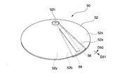
- the sheet material 52 is cut along the radial direction D51 at a predetermined position I in the circumferential direction D50. That is, a notch 56 extending from the stem penetrating opening 52 c to the outer edge of the sheet material 52 is provided at the position I.
- the width of the notch 56 in the circumferential direction D50 increases as it goes outward in the radial direction D51 from the communicating portion between the stem penetrating opening 52c and the notch 56.
- the one end 52a in the circumferential direction D50 of the sheet material 52 is configured to be detachable from the other end 52b.
- the bonding portion 58 is provided on the back surface 52 y in the vicinity of the end portion 52 a of the sheet material 52.
- a bonded portion 59 is provided on the surface 52 x in the vicinity of the end portion 52 b of the sheet material 52.
- the bonded portion 58 and the bonded portion 59 are configured by, for example, a magnet that can be attached to and detached from each other by magnetic force, Velcro (registered trademark), or the like.
- the bonded portion 58 and the bonded portion 59 are preferably magnets.
- a bonded portion 59 may be provided on the back surface 52 y in the vicinity of the end portion 52 a of the sheet material 52.
- An adhesive portion 58 may be provided on the surface 52 x in the vicinity of the end portion 52 b of the sheet material 52.
- an adhesive portion 58 may be provided on the surface 52 x in the vicinity of the end portion 52 a of the sheet material 52.
- a bonded portion 59 may be provided on the back surface 52 y in the vicinity of the end portion 52 b of the sheet material 52.
- the end portion 52 a overlaps the end portion 52 b of the sheet material 52 by bonding the bonding portion 58 to the bonded portion 59.
- the stem penetration opening 52c is closed in the circumferential direction D50 to form a stem penetration hole 52h, and the cover 50 is assembled.
- the cover 50 descends from the stem through hole 52h toward the outside in the radial direction D51 and has a shape like an umbrella.
- the cover 50 has a size that can cover the opening 14.
- the diameter of the cover 50 in plan view is at least larger than the diameter of the opening 14.
- the diameter of the sheet material 52 shown in FIG. 2 is set to be larger than the diameter of the cover 50 in plan view in accordance with the diameter of the cover 50 in plan view.
- the material of the sheet material 52 is not particularly limited as long as it has outdoor weather resistance and flexibility.
- a preferable material for the sheet material 52 is, for example, a synthetic rubber, a resin such as polycarbonate (PC), or the like.
- the nutrient solution supply unit 20 includes a nutrient solution tank 22 in which the nutrient solution W can be stored.
- a pump P is connected to the nutrient solution tank 22.
- An end 24 a on the downstream side of the nutrient solution supply pipe 24 is connected to the pump P.
- the diameter (outer diameter in the circumferential direction) of the downstream end 24 b of the nutrient solution supply pipe 24 is smaller than the diameter of the end 12 a of the pipe 12.
- the end portion 24 b of the nutrient solution supply pipe 24 and the end portion 12 a of the tube material 12 are connected by a joint 26 so that the end portion 24 b of the nutrient solution supply pipe 24 is disposed inside the end portion 12 a of the tube material 12. Therefore, the nutrient solution W pumped up from the nutrient solution tank 22 by the pump P is supplied to the hollow portion 12 s through the nutrient solution supply pipe 24.
- a filter for removing unnecessary components mixed in the nutrient solution W or a device for removing unnecessary components between the nutrient solution supply port of the nutrient solution tank 22 or between the nutrient solution tank 22 and the pump P Alternatively, a nutrient addition device or the like for adding a nutrient or the like for promoting the growth of the plant P may be provided.
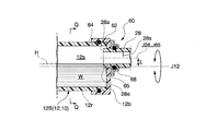
- the water level adjusting mechanism 60 is connected to the end 12b of the pipe 12 (that is, the end 12b on the downstream side of the pipe 12B).
- the water level adjusting mechanism 60 includes a joint 62 connected to the end 12b.
- the joint 62 has an introduction port 64 and a discharge port 65 having a diameter smaller than the diameter of the introduction port 64.
- the end portion 12 b of the tube material 12 is fitted into the introduction port 64.
- An upstream end portion 28 a of a nutrient solution discharge pipe 28 to be described later is fitted into the discharge port 65 through a sealing material 68. That is, the end portion 28 a of the nutrient solution discharge pipe 28 is disposed inside the end portion 12 b of the pipe material 12 via the joint 62.
- the discharge port 65 is provided at a position eccentric with respect to the introduction port 64, and is rotatable along the inside of the introduction port 64.
- the joint 62 is rotatable about the axis J12 while being in contact with the outer surface of the peripheral wall portion 12r of the tube material 12.
- the axis L65 of the discharge port 65 in the vertical direction and the interval L between the axis J28 of the nutrient solution discharge pipe 28 and the axis J12 of the pipe 12 change.
- the interval L the amount of nutrient solution W discharged from the hollow portion 12s to the hollow portion 28s of the nutrient solution discharge pipe 28 naturally changes.
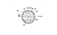
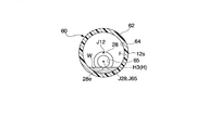
- the water level H of the nutrient solution W in the hollow portion 12s changes as shown in FIGS.
- the water level H is adjusted to the same heights H1, H2 and H3 as the lower end 28e of the hollow portion 28s.
- the water level H1 of the nutrient solution W is adjusted above the axis J12.
- the amount of the nutrient solution W in the hollow portion 12s is larger than when the axes J12, J28, J65 are at the same height.
- ⁇ Nutrient solution discharge pipe> As shown in FIG. 1, the downstream end portion 28 b of the nutrient solution discharge pipe 28 is connected to the nutrient solution tank 22 via a connection pipe (not shown). The nutrient solution W discharged to the hollow portion 28s returns to the nutrient solution tank 22 and can be reused.
- the hydroponic cultivation method of the first embodiment is a hydroponic cultivation method using the hydroponic cultivation apparatus 1 and includes a container arrangement step, a plant arrangement step, a cover arrangement step, a nutrient solution supply step, and a water level adjustment step.
- a container arrangement step a container arrangement step, a plant arrangement step, a cover arrangement step, a nutrient solution supply step, and a water level adjustment step.
- each step will be described.
- the pipe material 12 constituting the container 10 is disposed at a predetermined outdoor location.
- the support portion 40 is assembled at the predetermined location, and the tube material 12 is supported by the support portion 40 with the opening 14 facing upward.
- the nutrient solution supply unit 20 and the nutrient solution supply tube 24 are connected to the end portion 12a of the tube material 12, and the nutrient solution discharge tube 28 is connected to the end portion 12b.
- the rhizosphere R of the plant P is disposed in the hollow portion 12s of the tube material 12 from the outside through the opening 14 outdoors.
- the pot 30 is disposed in the hollow portion 12 s by passing the main body 30 b of the pot 30 from the bottom through the opening 14 and attaching the flange 32 to the opening 14.
- the root zone R is placed in the pot 30.
- the stalk C is inserted through the stalk through-hole 52h (stem-penetrating opening 52c) and the cover 50 is disposed in the container 10 so as to cover the opening 14.
- the stem C is inserted through the stem penetrating opening 52c.
- the end portion 52 a and the end portion 52 b are bonded, and the opening 14 and the rhizosphere R exposed in the opening 14 are covered with the cover 50.
- the stem C may be inserted through the stem through hole 52h in advance before the rhizosphere R is accommodated in the pot 30.
- the root zone R may be accommodated in the pot 30 and at the same time the root zone R exposed in the opening 14 may be covered with the cover 50.
- a predetermined amount of nutrient solution W is supplied to the hollow portion 12s by the nutrient solution supply unit 20 outdoors.
- the pump P is operated, and the nutrient solution W is supplied to the hollow portion 12s through the nutrient solution supply pipe 24 at a predetermined flow rate and flow rate.
- Water level adjustment process Basically, hydroponics is performed by performing the above-described nutrient solution supply process. Furthermore, you may adjust the water level H of the nutrient solution W in the hollow part 12s of the pipe material 12 using the water level adjustment mechanism 60 according to the growth condition etc. of the plant P outdoors. Specifically, the water level H can be adjusted by rotating the joint 62 about the axis J12.
- hydroponic cultivation of the plant P using the hydroponic cultivation apparatus 1 can be performed.
- the container 10 of the first embodiment Since the container 10 of the first embodiment has weather resistance, it is not deformed or deteriorated by ultraviolet rays or the like even when installed outdoors. Further, by forming the tube 12 and forming the tubular material 12, the length of the container 10 can be set and changed to a desired length. That is, if the tube material 12 is appropriately cut or a plurality of tube materials 12 are freely connected, the overall shape and configuration of the container 10 can be flexibly changed.
- the container 10 is made of resin, it is lightweight. Thereby, the operator who performs hydroponics is easy to carry the container 10, and handling of the container 10 becomes easy.
- the container 10 By forming the container 10 with polyvinyl chloride having a mature molding technique, the container 10 can be manufactured easily and at low cost.
- the container 10 has an opening 14 and includes a pot 30. Therefore, if the rhizosphere R is disposed inside the main body 30b, the plant P can be easily planted, and the rhizosphere R can be stabilized by the hollow portion 12s. Moreover, if the rhizosphere R is extracted from the inside of the main body 30 b or the rhizosphere R is extracted from the container 10 together with the pot 30, the plant P can be easily removed and replaced with respect to the container 10.
- the cover 50 of the first embodiment when the rhizosphere R is disposed in the opening 14, the stem C above the rhizosphere R is caused to penetrate the stem through hole 52 h / the stem penetrating opening 52 c.
- the cover 50 can be easily installed above the opening 14 without damaging the stem.
- the outer diameter of the sheet material 52 is larger than the outer diameter of the opening 14 and the cover 50 has a size capable of closing the opening 14, the opening 14 can be reliably covered without a gap.
- the cover 50 having weather resistance can shield the rhizosphere R so that rainwater, soil, and other obstacles / garbage do not enter the rhizosphere R.
- the hydroponic cultivation container, hydroponic cultivation cover, hydroponic cultivation apparatus, and hydroponic cultivation method according to the present invention can be applied to plant cultivation using microorganisms. Even when cultivation is performed, it is possible to shield the ultraviolet rays by the cover 50, or to suppress the mixing of harmful substances contained in the surrounding soil and rainwater. Therefore, long-term stable outdoor cultivation can be performed while suppressing the death of microorganisms by ultraviolet rays or harmful substances.
- limiting in particular about the said microorganisms For example, the microorganisms etc. which are known to construct
- the cover 50 of the first embodiment is easily assembled by adhering the end portion 52a and the end portion 52b of the sheet material 52 after passing the stem C through the stem through hole 52h, and is installed above the opening 14. Is done. Since the sheet material 52 has the stem through-hole 52h, the plant P such as the stem C can be prevented from being damaged when the cover 50 is installed in the container 10. When removing the cover 50, the end 52a and the end 52b of the sheet material 52 may be separated from each other, and the stem C may be removed from the stem penetrating opening 52c. Thus, handling of the cover 50 is simple. Moreover, the shape of the cover 50 can be changed flexibly by freely changing the shape of the sheet material 52 before assembly.
- a magnet (adhered portion 58) is provided on the back surface 52 y in the vicinity of the end portion 52 a of the sheet material 52, and a magnet (adhered portion 59) is provided on the surface 52 x in the vicinity of the end portion 52 b of the sheet material 52. Therefore, the end 52a and the end 52b can be easily and easily attached and detached. Thereby, the cover 50 can be handled more easily.
- the hydroponic cultivation apparatus 1 includes a container 10, a cover 50, and a nutrient solution supply unit 20.
- the hydroponic cultivation apparatus 1 has weather resistance to prevent deformation and deterioration of the container 10 and the cover 50 due to weather and the like, and can be used outdoors for a long time.
- the container 10 is comprised by simple work, the plant P is planted in the container 10, and while protecting the rhizosphere R exposed to the opening 14 with the cover 50, the pump P is operated. If it is made, the plant P can be hydroponically cultivated almost automatically. That is, hydroponics can be performed easily and easily.
- the configuration of the container 10 can be easily changed, the arrangement of the plant P and the flow path of the nutrient solution W can be changed flexibly.
- the shape of the container 10 of the hydroponic cultivation apparatus 1 is increased by increasing the number of joints 18 that connect the plurality of pipe materials 12 and connecting the plurality of pipe materials 12 in a desired overall shape and pattern using the joints 18. -The configuration can be easily changed.
- the hydroponic cultivation apparatus 1 By using the hydroponic cultivation apparatus 1, the nutrient solution W can be supplied to the hollow portion 12s by the nutrient solution supply unit 20, and the nutrient solution W can be absorbed from the rhizosphere R arranged in the hollow portion 12s. Therefore, the hydroponics apparatus 1 can be installed outdoors, and the plant P can be hydroponically cultivated outdoors.
- the hydroponic cultivation device By using the hydroponic cultivation device 1, if the water level adjustment mechanism 60 is connected to the pipe material 12, the water level H of the nutrient solution W in the hollow portion 12 s can be easily reduced using the water level adjustment mechanism 60 while suppressing an increase in the size of the device. Can be adjusted.
- the water level H of the nutrient solution W supplied to the hollow part 12s is so low that the center of the discharge port 65 is arrange
- each component of the hydroponic cultivation apparatus 1 is lightweight and easy to handle and does not require soil, hydroponic cultivation can be easily carried out regardless of the location, such as the desert, the basement, or the rooftop of a building.
- the hydroponic cultivation method of the first embodiment is a hydroponic cultivation method using the hydroponic cultivation apparatus 1, and includes a container placement step of placing the container 10 in a predetermined place, and the root zone R through the opening 14.
- a container placement step of placing the container 10 in a predetermined place, and the root zone R through the opening 14.
- the cover placement step of penetrating the stem C through the stem through-hole 12h and placing the cover 50 in the container 10 so as to cover the opening 14, and the nutrient solution supply unit 20
- a nutrient solution supply step for supplying the nutrient solution W to the inside of the container 10.
- the rhizosphere R is inserted into the opening 14, the stem C is inserted into the stem through-hole 12 h, and the end 52 a of the sheet material 52 is bonded to the end 52 b.
- the cover 50 can be easily installed above the cover 14 and the opening 14 and the rhizosphere R can be reliably covered with the cover 50.
- the hydroponics method of the first embodiment further includes a water level adjustment step of adjusting the water level H of the nutrient solution W in the hollow portion 12s using the water level adjustment mechanism 60.
- a control mechanism or an expensive adjusting mechanism having a complicated structure is provided in a state where the supply amount of the nutrient solution W pumped from the nutrient solution supply unit 20 and supplied to the hollow portion 12s of the pipe 12 is constant. Even if it does not use etc., the water level H of the nutrient solution W in the hollow part 12s of the pipe material 12 can be adjusted easily and easily.
- a predetermined amount of nutrient solution W is supplied to the hollow portion 12s by the nutrient solution supply unit 20, and the water level H of the nutrient solution W in the hollow portion 12s using the water level adjustment mechanism 60. Can be adjusted. Further, the water level H of the nutrient solution W in the hollow portion 12s can be easily adjusted while keeping the supply amount of the nutrient solution W from the nutrient solution supply unit 20 at a predetermined amount.
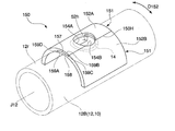
- the hydroponic cultivation apparatus (not shown) of the second embodiment according to the present invention includes a cover 150 shown in FIG. 9 instead of the cover 50 of the hydroponic cultivation apparatus 1 of FIG. It comprises the following elements.
- symbol is attached
- the cover 150 includes a first member 152A and a second member 152B connectable to the first member 152A.
- the first member 152A and the second member 152B are made of a sheet material 151 having outdoor weather resistance and flexibility.
- the first member 152A and the second member 152B can be attached to the peripheral wall portion 12r of the pipe material 12 (that is, the container 10).
- the first member 152A and the second member 152B are formed so as to abut on the peripheral wall portion 12r in the D152 direction (the connecting direction of the first member and the second member).
- the first member 152A and the second member 152B are curved so as to trace the outer surface of the peripheral wall portion 12r above the axis J12.
- the first member 152A and the second member 152B are connectable along the axis J12 at the upper end portion of the peripheral wall portion 12r.
- a stem penetration hole 154A is formed in the first connecting portion 155 of the first member 152A on the second member 152B side.
- a stem penetrating opening 154B is formed in the second connecting portion 156 on the first member 152A side of the second member 152B.
- the stem penetration holes 154A and 154B have a size that allows the stem C of the plant P to be inserted therethrough, and are formed in a substantially circular or semicircular shape in plan view.
- the stem penetrating opening 154A opens to the connecting end surface 159C on the second member 152B side of the first member 152A.
- the stem penetrating opening 154B opens on the connection end surface 159D of the second member 152B on the first member 152A side.
- the first member 152A and the second member 152B may be composed of sheet materials of the same material or may be composed of sheet materials of different materials.
- the lower side of the first connecting part 155 is cut out, and the upper side of the second connecting part 156 is cut out.
- the second connecting portion 156 is fitted below the first connecting portion 155.
- one of the bonding portion 58 and the bonded portion 59 (not shown) is provided on the lower surface 158 of the first connecting portion 155.
- the other of the bonded portion 58 and the bonded portion 59 is provided on the upper surface 157 of the second connecting portion 156.
- the bonded portion 58 and the bonded portion 59 are configured by, for example, a magnet that can be attached to and detached from each other, Velcro (registered trademark), or the like. In order to easily attach and detach the bonded portion 58 and the bonded portion 59, the bonded portion 58 and the bonded portion 59 are preferably magnets.
- the connecting end surface 159C is attached to the connecting end surface 159B
- the connecting end surface 159D is attached to the connecting end surface 159A.
- the stem penetration hole 52h is formed by arrange
- the pot 30, the bonding portion 58, and the bonded portion 59 are omitted.
- connection method of the first member 152A and the second member 152B is not limited to the above-described method.
- the connection state between the first member 152A and the second member 152B can be stabilized, and it is only necessary that the first member 152A and the second member 152B are difficult to come off.
- one of the bonding portion 58 and the bonded portion 59 may not be on the lower surface 158 of the first connecting portion 155 and the other of the bonding portion 58 and the bonded portion 59 may not be on the upper surface 157 of the second connecting portion 156.
- the 2nd connection part 156 fits under the 1st connection part 155, and a tape may be affixed on the joint 150H of the 1st member 152A and the 2nd member 152B of a connection state.
- the connected first member 152A and second member 152B may be fixed from the outside along the connecting direction with rubber, tape, string, or the like.
- the lower side of the first connecting portion 155 and the upper side of the second connecting portion 156 may not be cut out, and the connecting end surface 159C and the connecting end surface 159A may be flush with each other.
- the connecting end surface 159D and the connecting end surface 159B may be flush with each other.
- connection end surfaces 159C and 159D has one of the bonded portion 58 and the bonded portion 59.
- the other of the connection end surfaces 159C and 159D has the other of the bonding portion 58 and the bonded portion 59.
- one member of the first member 152A and the second member 152B has an engaging claw, and the other member of the first member 152A and the second member 152B has an engaged recess in which the engaging claw can be engaged. May be. In any of the configurations described above, the first member 152A and the second member 152B can be easily connected, and the first member 152A and the second member 152B in the connected state are unlikely to come off.
- the cover 150 has a size that can cover the opening 14.
- the length and width of the cover 150 in plan view are at least larger than the diameter of the opening 14.
- the length and width of the first member 152A and the second member 152B shown in FIG. 2 are set in accordance with the length and width of the cover 150 in plan view.
- the material of the sheet material 151 has outdoor weather resistance and flexibility. If the first member 152A and the second member 152B can be easily connected and separated, and are difficult to separate from each other in the connected state, the material of the sheet material 151 is not particularly limited.
- a preferable material for the sheet material 52 is, for example, a resin material such as PVC, PE, or polypropylene.
- the hydroponic cultivation method of the second embodiment is a hydroponic cultivation method using the hydroponic cultivation apparatus of the second embodiment.
- the hydroponics method of 2nd embodiment is equipped with the container arrangement
- the container arrangement process, plant arrangement process, nutrient solution supply process, and water level adjustment process of the second embodiment are exactly the same as those of the first embodiment. Below, only the cover arrangement
- the cover 150 is disposed in the container 10 so as to cover the opening 14 by allowing the stem C to penetrate the stem through hole 52h (the stem penetrating opening portion 154A or the stem penetrating opening portion 154B) outdoors. (See FIG. 9). Specifically, the stem C is penetrated through the stem penetration hole 154A (or the stem penetration hole 154B).
- the cover 150 is assembled by connecting and fixing the first connecting portion 155 and the second connecting portion 156.
- the cover 150 covers the opening 14 and the rhizosphere R exposed in the opening 14. Note that, before the rhizosphere R is accommodated in the pot 30, the stem C may be penetrated through the stem penetrating opening 154A in advance. Thereafter, the cover 150 may be assembled by connecting and fixing the first connecting portion 155 and the second connecting portion 156. Furthermore, the rhizosphere R may be covered with the cover 150 at the same time when the rhizosphere R is accommodated in the pot 30.
- first modification of the cover 150, the first member 152A, and the second member 152B there are a cover 160, a first member 162A, and a second member 162B shown in FIGS.
- the first member 162A and the second member 162B are coupled along the D162 direction (the coupling direction of the first member and the second member).
- the direction D162 is a direction in contact with the upper end of the tube 12B in the horizontal plane and orthogonal to the axis J12.
- a part of the first member 162A and the second member 162B is in contact with the peripheral wall portion 12r.
- the remaining portions of the first member 162A and the second member 162B are separated from the peripheral wall portion 12r toward the outside in the radial direction of the tube 12B.
- the first member 162A and the second member 162B of the first modified example have an upper surface 163 extending along the direction D162 and a side surface 164 descending from the outer end of the upper surface 163 in the direction D152.
- the upper surface 163 of the first member 162A is in contact with the upper end of the tube 12B along the axis J12 at the first connecting portion 155 via the second connecting portion 156.
- the upper surface 163 of the second member 162B is in direct contact with the upper end of the tube 12B along the axis J12 at the second connecting portion 156.
- Lower portions of the side surfaces 164 of the first member 162A and the second member 162B are in direct contact with the side ends of the tube 12B along the axis J12.
- the connecting end surface 159C is connected to the connecting end surface 159B
- the end surface 159D is connected to the connection end surface 159A.
- the cover 170, the first member 172A, and the second member 172B shown in FIGS. 12 and 13 are examples of the second modification of the cover 150, the first member 152A, and the second member 152B.
- the cover 170 of the second modification has the same configuration as the cover 160. That is, a part of the first member 172A and the second member 172B is in contact with the peripheral wall portion 12r along the peripheral wall portion 12r. The remaining portions of the first member 172A and the second member 172B are separated from the peripheral wall portion 12r toward the outside in the radial direction of the tube 12B.
- the first member 162 ⁇ / b> A and the second member 162 ⁇ / b> B of the second modification have an inclined surface 173 and a side surface 164.
- the inclined surface 173 descends from the upper end of the tube 12B and from the center in the width direction toward the side end when viewed from the upstream side along the axis J12.
- the side surface 164 descends from the outer end of the inclined surface 173 in the D172 direction (the direction in which the first member and the second member are connected).
- the inclined surfaces 173 of the first member 162A and the second member 162B are in contact with the peripheral wall portion 12r at the substantially central portion along the direction D172.
- the connecting end surface 159C is coupled to the connecting end surface 159B, and the connection is made.
- End surface 159D couples to connecting end surface 159A.
- the stem penetration hole 154A and the stem penetration hole 154B are overlapped to form the stem penetration hole 52h, the cover 170 is assembled.
- the connection strength of the 1st connection part 155 and the 2nd connection part 156 increases because the 1st connection part 155 and the 2nd connection part 156 have refracted in the mountain shape.
- the cover 150 of the second embodiment connects the first member 152A and the second member 152B by adhering the first connecting part 155 and the second connecting part 156 after the stem C has penetrated the notch part 142A. Is easily assembled and installed above the opening 14. When removing the cover 150, the connection state between the first member 152A and the second member 152B is released, and the stem C may be removed from the notch 142A (or the notch 142B). Thus, handling of the cover 150 is easy. Moreover, the shape of the cover 50 can be changed flexibly by freely changing the shapes of the first member 152A and the second member 152B.
- a magnet (adhered portion) is provided on the lower surface 158 of the first connecting portion 155, and a magnet (adhered portion) is provided on the upper surface 157 of the second connecting portion 156.
- the 1st connection part 155 and the 2nd connection part 156 can be attached and detached easily and easily. Thereby, the cover 150 can be more easily handled.
- the hydroponic cultivation apparatus of the second embodiment other than the cover 150 has the same configuration as the hydroponic cultivation apparatus 1 of the first embodiment other than the cover 50. Therefore, the effect similar to the hydroponic cultivation apparatus 1 is obtained by the hydroponic cultivation apparatus of the second embodiment.
- the elbow 12E and the pipes 12A and 12B may be formed as a single pipe material.
- the plurality of tubes 12A, 12B,... Do not have to be linearly connected as illustrated in FIG.
- the elbow 12E and the pipes 12A and 12B may be connected, for example, in a ring shape or a U shape in plan view.
- several 12A, 12B, ... may be provided in parallel in the height direction.
- the hydroponic cultivation device 1 may not be equipped with the nutrient solution tank 22 or the like, and may be configured so that seawater or fresh water can be directly introduced into the hydroponic cultivation device 1. Seawater or fresh water drawn to the hydroponic cultivation apparatus 1 may be supplied as the nutrient solution W to the nutrient solution supply pipe 24 or the tube material 12.
- the upstream end 24a of the nutrient solution supply pipe 24 may be connected to a lake, a bay, a lake, or an underground hydrous layer.
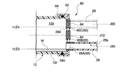
- the discharge port 65 of the joint 62 does not rotate along the inside of the introduction port 64, and on the other hand, there is a water level adjusting mechanism 70 which is provided at a fixed position and in which a partition plate 72 (so-called gate valve) is provided at the discharge port 65.
- a partition plate 72 so-called gate valve
- the diameter of the discharge port 65 does not necessarily have to be smaller than the diameter of the introduction port 64 and may be the same.
- the partition plate 72 is configured to be operable from below the discharge port 65 because the water level H of the nutrient solution W can be adjusted in detail according to the movement of the partition plate 72. It is preferable to be configured to be movable along the vertical direction. Thereby, the water level H of the nutrient solution W can be easily adjusted to a desired water level by appropriately moving the partition plate 72 in the vertical direction.
- the upper end 72d of the partition plate 72 is set to the height E1
- the water level H of the nutrient solution W becomes the same as the height E1
- the partition plate 72 is moved in the direction D72 (that is, upward) as shown by a broken line in FIG. )
- the upper end 72d is raised to the height E2
- the water level H of the nutrient solution W is also raised to the height E2.
- the water level adjusting mechanism 70 includes a joint 62 connected to the pipe material 12.
- the joint 62 includes an introduction port 64 and a discharge port 65.
- the pipe material 12 is connected to the introduction port 64, and a partition plate 72 that can be freely opened and closed is provided at the discharge port 65.
- the size of the discharge port 65 is changed by opening and closing the partition plate 72. Therefore, the water level H of the nutrient solution W in the hollow portion 12s can be easily adjusted by simply opening and closing the partition plate 72.
- the partition plate 72 When the partition plate 72 is lowered by using the water level adjusting mechanism 70, the height of the lower end of the discharge port 65 through which the nutrient solution W can flow is reduced. On the other hand, when the partition plate 72 is raised, the height of the lower end of the discharge port 65 through which the nutrient solution W can flow increases, and the water level H of the hollow portion 12s rises. As described above, the height of the lower end of the discharge port 65 through which the nutrient solution W can flow is changed by opening and closing the partition plate 72. Therefore, the water level H of the nutrient solution W in the hollow portion 12s can be easily adjusted according to the opening / closing amount of the partition plate 72.
- the water level adjustment mechanism 60 for example, as shown in FIG. 15, there is no particular limitation as long as it is other than a predetermined direction of the joint 62 (for example, other than the horizontal direction / lateral direction of the inlet 64, the circumferential direction or A plurality of discharge ports 65 are formed along the vertical direction, etc., and at least one of these discharge ports 65 is provided at a position eccentric with respect to the introduction port 64 and does not rotate along the inside of the introduction port 64. And a water level adjusting mechanism 80 that can be opened and closed by a cap 84 or the like.
- the number of discharge ports 65 is not particularly limited, but is preferably 4 to 5, for example.
- the water level adjusting mechanism 80 is configured by a joint connected to the pipe material 12, and the joint includes an introduction port and a plurality of discharge ports having a smaller diameter than the introduction port, and the pipe material is connected to the introduction port.
- Each of the plurality of discharge ports is provided at a position eccentric with respect to the introduction port, and is configured to be openable and closable.
- the water level H of the nutrient solution W in the hollow portion 12s can be easily adjusted according to the height of the lower end of the opened outlet by appropriately selecting what is to be opened among the plurality of outlets. .
- the nutrient solution discharge pipe 28 is connected to a desired discharge port 65 among the plurality of discharge ports 65, and the other discharge ports 65 are closed with a cap 84 or the like.
- the water level H of the nutrient solution W is changed to the vicinity of the lower end of the discharge port 65 to which the nutrient solution discharge pipe 28 is connected. Therefore, the water level H of the nutrient solution W can be easily adjusted to a desired water level by changing the discharge port 65 connecting the nutrient solution discharge pipe 28.
- FIG. 15 the water level in which three discharge ports 65 ⁇ / b> A, 65 ⁇ / b> B, 65 ⁇ / b> C are provided along the vertical direction when the connecting portions of the joint 62, the pipe material 12, and the nutrient solution discharge pipe 28 are viewed from the side.
- the adjustment mechanism 80 is shown.
- the discharge ports 65 ⁇ / b> A and 65 ⁇ / b> C are provided at positions that are eccentric with respect to the introduction port 64, but the discharge port 65 ⁇ / b> B is provided at a position that is not substantially eccentric with respect to the introduction port 64.
- the water level H of the nutrient solution W becomes the height E3 (that is, the nutrient solution discharge pipe).
- the nutrient solution discharge pipe 28 is connected to the discharge port 65C formed on the uppermost side and the discharge ports 65A and 65B are closed with the cap 84 as shown by the broken line in FIG. 15, the water level H of the nutrient solution W is high. It rises to E4.
- the sheet material 52 in the first embodiment may be provided with a cutting line at the position I communicating with the piercing hole 52c instead of the notch 56.
- the present invention can be widely used in the field related to hydroponics.
- the hydroponic cultivation apparatus and the hydroponic cultivation method according to the present invention can be implemented at any place as long as nourishing liquid can be supplied even without soil, so that conventionally, hydroponic cultivation has been difficult, such as deserts and underground It can be used for hydroponics.
Landscapes
- Life Sciences & Earth Sciences (AREA)
- Environmental Sciences (AREA)
- Engineering & Computer Science (AREA)
- Water Supply & Treatment (AREA)
- Cultivation Receptacles Or Flower-Pots, Or Pots For Seedlings (AREA)
- Hydroponics (AREA)
Abstract
本発明を適用した水耕栽培装置(1)は、容器(10)、カバー(50)、容器(10)の中空部(12s)に養液(W)を供給する養液供給部(20)、水位調整機構(60)を備える。容器(10)は、管状に形成される。カバー(50)は、根圏(R)を保護し、容器(10)の開口(14)を覆うことができる大きさを有する。水位調整機構(60)は、容器(10)に連結され、中空部(12s)における養液(W)の水位を調整できる。
Description
本発明は、水耕栽培用容器、水耕栽培用カバー、水耕栽培装置および水耕栽培方法に関する。本願は、2017年2月2日に日本に出願された特願2017-017879号、特願2017-017880号および特願2017-017881号に基づき優先権を主張し、その内容をここに援用する。
野菜等の植物の栽培方法には、天然の環境と土壌で植物を栽培する露地栽培と、栽培環境を制御し、成長に必要な養分を養液として植物に供給することで植物を栽培する養液栽培がある。養液栽培の中でも土壌を使用しない栽培方法は、水耕栽培と呼ばれている。水耕栽培は、植物の成長に必要な養分を植物に供給しつつ、光、温度、養液量等の栽培環境を最適化することで、季節に関係なく植物の生産が可能になるという利点を有する。栽培環境における光、温度、及び養液量の制御方法をはじめとする水耕栽培の技術に関して、様々な検討が進んでいる。現状では、水耕栽培はビニールハウス内などの屋内で行われることが多いが、屋内の栽培環境を常に最適な条件に制御しつつ植物の栽培を行うと、手間やコストがかかるため、屋外での水耕栽培が望まれている。
例えば、特許文献1には、コンクリート製のU字溝を用いた水耕栽培装置が開示されている。特許文献1の水耕栽培装置は、コンクリート製のU字溝を一直線上に傾斜させて並べたものである。U字溝列の全長にわたってU字溝の内面に不透水性のプラスチック製のシートが敷設され、コンクリート製の液漏れ防止板によってシートの内側の空間がU字溝列の長手方向に沿って複数に区画されている。各区画内に植物が配置される。
しかしながら、特許文献1に記載の水耕栽培装置では、コンクリート製のU字溝を用いることにより問題が生じる。即ち、水耕栽培用容器の重量が増大し、水耕栽培装置の設置に手間がかかり、水耕栽培装置の構成をフレキシブルに変更することが難しいという問題があった。また、従来の水耕栽培では、簡易な構成を有し、製造が容易であり、取り扱い易く、構成の変更が容易な水耕栽培装置を用いて屋外で行われている事例はない。さらに、従来は、屋外での水耕栽培に用いる水耕栽培用容器、水耕栽培用カバー、水耕栽培装置、および水耕栽培方法に関する十分な検討がなされていなかった。
また、水耕栽培では、植物の根圏を遮光したり、根圏に雨水や土が入らないように配慮することが望ましい。特許文献1に記載の水耕栽培装置では、コンクリート製蓋の上方に、アーチ状に設置されたプラスチックフィルムによって根圏に雨水や土が入らないようにされている。また、特許文献1に記載されている反射又は遮光プレートも、根圏を遮光し、根圏に雨水や土が入らないようにする役割を担っている。しかしながら、前記プラスチックフィルムや反射又は遮光プレートを設置する際に、植物の茎などを傷付けないように注意する必要があり、設置が難しいという問題があった。さらに、植物の茎などを傷付けないように植物の周囲に十分な隙間を設けて設置しようとすると、根圏の遮光や、根圏に雨水や土が入ることを防止する効果が不十分になるという問題があった。
さらに、水耕栽培では、植物の種類や生育状況に応じて水耕栽培用容器の内部における養液の水位を調整することが重要である。従来の水耕栽培装置では、養液供給部に付設する養液供給量制御機構や水位センサを用いて、水耕栽培用容器の内部における養液の水位を調整する。しかしながら、このような従来の水位調整方法では、装置が大がかりになるという問題があった。また、特許文献1に記載の水耕栽培装置では、一旦設置されたU字溝列の傾斜角度や溢流堰板の形状を変更するのは手間と労力がかかるという問題があった。
本発明は、上述の問題を鑑みてなされたものであり、簡易な構成を有し、製造が容易であり、取り扱い易く、構成の変更が容易な水耕栽培に用いる水耕栽培用容器、水耕栽培用カバー、水耕栽培装置、および、該水耕栽培装置を用いた水耕栽培方法を提供する。
本発明の水耕栽培用容器は、屋外耐候性を有し、かつ、中空管を含み、前記中空管の中空部に植物の根圏を配置するための少なくとも1つの開口が前記中空管の周壁部に形成されていることを特徴とする。
本発明の水耕栽培用容器では、前記中空管は樹脂により形成されていてもよく、前記樹脂はポリ塩化ビニルであってもよい。
本発明の水耕栽培用容器は、さらに有底筒状のポットを含み、前記ポットは、その上端部が前記開口の周縁に引っ掛けられた状態で前記中空部に保持されており、前記ポットの側壁部および底部には孔が形成されていてもよい。
本発明の水耕栽培用容器は、さらに有底筒状のポットを含み、前記ポットは、その上端部が前記開口の周縁に引っ掛けられた状態で前記中空部に保持されており、前記ポットの側壁部および底部には孔が形成されていてもよい。
本発明の水耕栽培用カバーは、水耕栽培により栽培されている植物の根圏を覆う水耕栽培用カバーであって、屋外耐候性および可撓性を有するシート材を含み、前記シート材は、その中央部に、前記植物の茎の直径よりも大きな直径を有する茎貫通用開孔部、及び前記茎貫通用開孔部から前記シート材の外縁端部に亘って延びる切欠又は切断線を有することを特徴とする。
本発明の水耕栽培用カバーでは、前記シート材は、前記切欠または前記切断線の両側の表面部分であって、かつ、その近傍に少なくとも1対のマグネットが設けられており、前記少なくとも1対のマグネットは、磁力により前記シート材の前記切欠または前記切断線の両側の部分を重ね合わせて接触させた状態で保持できるように配置されていてもよい。
本発明の水耕栽培用カバーは、水耕栽培により栽培されている植物の根圏を覆う水耕栽培用カバーであって、屋外耐候性および可撓性を有し、前記植物が配置される水耕栽培用容器の周壁部に取り付け可能な第一部材と、屋外耐候性および可撓性を有し、前記水耕栽培用容器の周壁部に取り付け可能な第二部材と、を備え、前記第一部材は、前記第二部材と連結するための第一連結部を有しており、前記第二部材は、前記第一部材と連結するための第二連結部を有しており、前記第一連結部及び前記第二連結部のそれぞれに切欠部が形成されており、前記第一部材と前記第二部材とは、前記第一連結部及び前記第二連結部において連結され、ここで、前記第一連結部の切欠部と前記第二連結部の切欠部が協働して、前記植物の茎の直径よりも大きな直径を有する茎貫通孔を形成することを特徴とする。
本発明の水耕栽培用カバーでは、前記第一部材と前記第二部材との連結部において前記周壁部に当接するように形成されてもよい。
本発明の水耕栽培用カバーでは、一部分は前記周壁部に接し、残りの部分は前記周壁部に接していなくてもよい。
本発明の水耕栽培用カバーでは、前記第一連結部と前記第二連結部に少なくとも1対のマグネットが設けられており、前記少なくとも1対のマグネットは、磁力により前記第一連結部と前記第二連結部とを重ね合わせて接触させた状態で保持できるように配置されていてもよい。
本発明の水耕栽培用カバーでは、一部分は前記周壁部に接し、残りの部分は前記周壁部に接していなくてもよい。
本発明の水耕栽培用カバーでは、前記第一連結部と前記第二連結部に少なくとも1対のマグネットが設けられており、前記少なくとも1対のマグネットは、磁力により前記第一連結部と前記第二連結部とを重ね合わせて接触させた状態で保持できるように配置されていてもよい。
本発明の水耕栽培装置は、上記の水耕栽培用容器と、上記の水耕栽培用カバーと、前記中空部に養液を供給する養液供給部と、を備え、前記水耕栽培用カバーは前記水耕栽培用容器の開口を覆うことができる大きさを有することを特徴とする。
本発明の水耕栽培装置では、前記中空部における前記養液の水位を調整可能な水位調整機構をさらに備え、前記水位調整機構は前記水耕栽培用容器に連結可能に構成されてもよい。
本発明の水耕栽培装置では、前記水位調整機構は、前記水耕栽培用容器の中空管に接続される継手で構成され、前記継手は導入口と前記導入口よりも小さい径の排出口とを備え、前記導入口に前記中空管が接続され、前記排出口が前記導入口に対して偏心した位置に設けられるとともに、前記継手が、前記中空管の中心軸を回転軸として回転可能に構成されてもよい。
本発明の水耕栽培装置では、前記水位調整機構は、前記管材に接続される継手で構成され、前記継手は導入口と排出口とを備え、前記導入口に前記管材が接続され、前記排出口に開閉自在の仕切板が設けられてもよい。
本発明の水耕栽培装置では、前記仕切板は上下方向に移動可能となるように構成されてもよい。
本発明の水耕栽培装置では、前記仕切板は上下方向に移動可能となるように構成されてもよい。
本発明の水耕栽培装置では、前記水位調整機構は、前記管材に接続される継手で構成され、前記継手は導入口と該導入口よりも小さい径かつ複数の排出口とを備え、前記導入口に前記管材が接続され、前記複数の排出口の各々が前記導入口に対して偏心した位置に設けられるとともに、開閉可能に構成されてもよい。
本発明の水耕栽培方法は、上記の水耕栽培装置を用いた水耕栽培方法であって、前記水耕栽培用容器を所定の場所に配置する容器配置工程と、前記開口を通して前記植物の根圏を前記水耕栽培用容器の内部に入れる植物挿入工程と、前記茎貫通孔に前記植物の茎を貫通させ、前記開口を覆うように前記水耕栽培用カバーを前記水耕栽培用容器に配置するカバー配置工程と、前記養液供給部によって前記内部に前記養液を供給する養液供給工程と、を備えたことを特徴とする。
本発明の水耕栽培方法は、上記の水耕栽培装置を用いた水耕栽培方法であって、前記水耕栽培用容器を所定の場所に配置する容器配置工程と、前記開口を通して前記植物の根圏を前記水耕栽培用容器の内部に入れる植物挿入工程と、前記茎貫通孔に前記植物の茎を貫通させ、前記開口を覆うように前記水耕栽培用カバーを前記水耕栽培用容器に配置するカバー配置工程と、前記養液供給部によって前記内部に前記養液を供給する養液供給工程と、前記水位調整機構を用いて前記中空部における前記養液の水位を調整する水位調整工程と、を備えたことを特徴とする。
本発明の水耕栽培方法では、前記容器配置工程を屋外で行ってもよい。
本発明によれば、簡易な構成を有し、製造が容易であり、取り扱い易く、構成の変更が容易な水耕栽培に用いる水耕栽培用容器、水耕栽培用カバー、水耕栽培装置、および、該水耕栽培装置を用いた水耕栽培方法を提供できる。
以下、本発明に係る水耕栽培用容器、水耕栽培用カバー、水耕栽培装置、および、水耕栽培方法について、図面を参照して説明する。なお、以下の説明で用いる図面は、模式的なものである。図面中の各構成要素の長さ、幅、及び厚みの比率等は実際のものと同一とは限らない。また、以下の説明において例示される材料等は一例であって、本発明はそれらに限定されない。以下で説明する内容は、本発明の要旨を変更しない範囲で適宜変更可能である。
(第一実施形態)
[水耕栽培装置]
図1に示すように、本発明に係る第一実施形態の水耕栽培装置1は、容器(水耕栽培用容器)10と、養液供給部20と、カバー(水耕栽培用カバー)50と、ポット30と、水位調整機構60と、を備える。養液供給部20は、容器10の中空部12sに養液Wを供給する。カバー50は、中空部12sに配置された植物Pの根圏Rを覆って保護する。ポット30は、中空部12sに配置される。水位調整機構60は、中空部12sにおける養液Wの水位を調整可能にする。
[水耕栽培装置]
図1に示すように、本発明に係る第一実施形態の水耕栽培装置1は、容器(水耕栽培用容器)10と、養液供給部20と、カバー(水耕栽培用カバー)50と、ポット30と、水位調整機構60と、を備える。養液供給部20は、容器10の中空部12sに養液Wを供給する。カバー50は、中空部12sに配置された植物Pの根圏Rを覆って保護する。ポット30は、中空部12sに配置される。水位調整機構60は、中空部12sにおける養液Wの水位を調整可能にする。
水耕栽培装置1で栽培される植物Pは、例えばトマトであるが、水耕栽培可能であれば特に限定されない。
<水耕栽培用容器>
容器10は、中空部12sを含み、少なくとも一部は管状に形成される。本実施形態の容器10は、管材(中空管)12で構成される。
容器10は、中空部12sを含み、少なくとも一部は管状に形成される。本実施形態の容器10は、管材(中空管)12で構成される。
管材12は、エルボ12Eと、水平方向に略平行に延びる二本の管12A,12Bで構成される。二本の管12A,12Bは、継手18によって連結されている。エルボ12Eは、管12A,12Bの軸線(中心軸)J12に沿った方向から略垂直(図1の紙面の上側)に曲がる。したがって、エルボ12Eの上流側の端部12a(すなわち、管材12の上流側の端部12a)は、軸線J12に直交する方向に向いている。一方、管材12Aの上流側の端部は、エルボ12Eの下流側の端部の受け口に挿入される。管12Bの下流側の端部12bは、管材12の軸線J12に沿った方向に向く。
管材12の内径については特に制限はなく、栽培する植物の種類等に応じて適宜決定することができる。例えば、管材12の内径は、20mm~300mmであることが好ましく、40mm~150mmであることがより好ましく、50mm~100mmであることがさらに好ましい。管材12の内径が上記下限値以上であれば、根の生育する容積を十分に確保できるため植物の生長に有利であり、上記上限値以下であれば、資材重量が大きくなりすぎることを防止し、設置の容易性を確保することができる。
また、管材12の周壁部の厚みは特に制限されないが、例えば、1mm~10mmであることが好ましく、2mm~7mmであることがより好ましく、2mm~5mmであることがさらに好ましい。管材12の周壁部の厚みが上記下限値以上であれば、管材12は栽培する際に管材の形状を維持することに有利であり、上記上限値以下であれば、管材12の資材重量が大きくなりすぎることを防止し、設置の容易性を確保することができる。
管材12の内径については特に制限はなく、栽培する植物の種類等に応じて適宜決定することができる。例えば、管材12の内径は、20mm~300mmであることが好ましく、40mm~150mmであることがより好ましく、50mm~100mmであることがさらに好ましい。管材12の内径が上記下限値以上であれば、根の生育する容積を十分に確保できるため植物の生長に有利であり、上記上限値以下であれば、資材重量が大きくなりすぎることを防止し、設置の容易性を確保することができる。
また、管材12の周壁部の厚みは特に制限されないが、例えば、1mm~10mmであることが好ましく、2mm~7mmであることがより好ましく、2mm~5mmであることがさらに好ましい。管材12の周壁部の厚みが上記下限値以上であれば、管材12は栽培する際に管材の形状を維持することに有利であり、上記上限値以下であれば、管材12の資材重量が大きくなりすぎることを防止し、設置の容易性を確保することができる。
以下、本明細書では、管12A,12Bとエルボ12Eの各々を区別して記載する必要があるときのみ管12A,12Bとエルボ12Eを区別して記載する。それ以外のときは、管12A,12Bとエルボ12Eをまとめて管材12として記載する。
養液Wは中空部12sで流通する。管材12の周壁部12rに、開口14が形成されている。管材12は、端部12aと開口14が上側に開口するように配置されている。根圏Rは、管材12の外方から開口14を通して中空部12sに配置される。管材12は、地面等の床面Gから所定の高さに位置するように、支持部40によって支持されている。支持部40は、上下方向や水平方向に複数連結された棒状部材42を備える。なお、管材12は、地面に当接するように施設されてもよい。
管材12の素材は、屋外耐候性を有していれば、特に制限されない。管材12が軽量化される観点から、管材12が樹脂からなることが好ましい。管材12をなす好適な樹脂は、ポリ塩化ビニル(polyvinyl chloride:PVC)、ポリエチレン(polyethylene:PE)等が好ましい。管材12が前述の素材で構成されることで、管材12を容易に製造し、管材12の形状を変更し易く、且つ管材12の低コスト化を図ることができる。
尚、本発明において「屋外耐候性」を有するとは、屋外で使用された場合に、変形、変色、劣化等の変質を起こしにくい性質である。具体的には、例えば、以下の方法により屋外耐候性を評価することができる。放射照度255W/m2(300~700nm)、シャワーリング120分中18分間, ブラックパネル温度63±3℃、屋外用ガラスフィルター使用、槽内温度23℃、湿度50%の試験条件にてJIS K 7350に準拠したオープンフレームカーボンアークランプ(サンシャインカーボンアークランプ)照射を実施する。オープンフレームカーボンアークランプの照射開始から1500時間経過後の管材について、1/2偏平試験を行った結果、割れやヒビがなければ、「屋外耐候性」を有すると評価できる。照射するランプが、キセノンアークランプの場合、試験条件を放射照度60W/m2(300~400nm)、シャワーリングは120分中18分間、ブラックパネル温度63±3℃、屋外用ガラスフィルターを使用、槽内温度23℃、湿度50%としてもよい。
尚、本発明において「屋外耐候性」を有するとは、屋外で使用された場合に、変形、変色、劣化等の変質を起こしにくい性質である。具体的には、例えば、以下の方法により屋外耐候性を評価することができる。放射照度255W/m2(300~700nm)、シャワーリング120分中18分間, ブラックパネル温度63±3℃、屋外用ガラスフィルター使用、槽内温度23℃、湿度50%の試験条件にてJIS K 7350に準拠したオープンフレームカーボンアークランプ(サンシャインカーボンアークランプ)照射を実施する。オープンフレームカーボンアークランプの照射開始から1500時間経過後の管材について、1/2偏平試験を行った結果、割れやヒビがなければ、「屋外耐候性」を有すると評価できる。照射するランプが、キセノンアークランプの場合、試験条件を放射照度60W/m2(300~400nm)、シャワーリングは120分中18分間、ブラックパネル温度63±3℃、屋外用ガラスフィルターを使用、槽内温度23℃、湿度50%としてもよい。
<ポット>
ポット30は、管材12の外方から中空部12sに配置され、根圏Rを中空部12sで安定させる。ポット30は、内部に根圏Rを収容することができるように有底筒状に形成された本体30bを有する。本体30bは、底部に向かう程、やや縮径し、プラスチック等で形成される。本体30bの側壁部および底部には、多数の孔が形成されている。このことにより、植物Pの根が本体30bに良好にからむとともにポット30の外部と内部の間で養液Wが流通し易い。
ポット30は、管材12の外方から中空部12sに配置され、根圏Rを中空部12sで安定させる。ポット30は、内部に根圏Rを収容することができるように有底筒状に形成された本体30bを有する。本体30bは、底部に向かう程、やや縮径し、プラスチック等で形成される。本体30bの側壁部および底部には、多数の孔が形成されている。このことにより、植物Pの根が本体30bに良好にからむとともにポット30の外部と内部の間で養液Wが流通し易い。
ポット30は、本体30bの上端部から本体30bの上部開口の中心から離れる方向に向かって延びるフランジ32を有している。このフランジ32により、ポット30を開口14の周縁に引っ掛けられた状態で中空部12sに保持する。開口14の直径は、本体30bの上端部の直径より大きく、フランジ32の最大直径より小さい。したがって、フランジ32を開口14の周囲の管材12に引っ掛けて、本体30bを中空部12sに容易に配置することができる。
<水耕栽培用カバー>
図2に示すように、第一実施形態のカバー50は、平面視で略円形のシート材52で構成される。組み立てる前のシート材52の中心に、茎貫通用開孔部52cが形成される。茎貫通用開孔部52cの直径は、植物Pの茎C(図1参照)の直径より適度に大きい。シート材52は、周方向D50における所定の位置Iで径方向D51に沿って切断される。すなわち、茎貫通用開孔部52cからシート材52の外縁端部に亘って延びる切欠56が位置Iに設けられる。周方向D50における切欠56の幅は、茎貫通用開孔部52cと切欠56との連通箇所から径方向D51の外方に向かう程、大きくなる。
図2に示すように、第一実施形態のカバー50は、平面視で略円形のシート材52で構成される。組み立てる前のシート材52の中心に、茎貫通用開孔部52cが形成される。茎貫通用開孔部52cの直径は、植物Pの茎C(図1参照)の直径より適度に大きい。シート材52は、周方向D50における所定の位置Iで径方向D51に沿って切断される。すなわち、茎貫通用開孔部52cからシート材52の外縁端部に亘って延びる切欠56が位置Iに設けられる。周方向D50における切欠56の幅は、茎貫通用開孔部52cと切欠56との連通箇所から径方向D51の外方に向かう程、大きくなる。
シート材52の周方向D50における一方の端部52aは、他方の端部52bと着脱可能に構成される。第一実施形態では、接着部58がシート材52の端部52aの近傍の裏面52yに設けられる。被接着部59がシート材52の端部52bの近傍の表面52xに設けられる。接着部58および被接着部59は、例えば磁力により互いに着脱可能なマグネット、マジックテープ(登録商標)等で構成される。接着部58と被接着部59とを容易に着脱可能とするために、接着部58および被接着部59はマグネットであることが好ましい。
接着部58と被接着部59は、交換可能である。シート材52の端部52aの近傍の裏面52yに被接着部59が設けられてもよい。シート材52の端部52bの近傍の表面52xに、接着部58が設けられてもよい。また、シート材52の端部52aの近傍の表面52xに接着部58が設けられてもよい。シート材52の端部52bの近傍の裏面52yに、被接着部59が設けられてもよい。
図3に示すように、接着部58が被接着部59に接着されることによって、シート材52の端部52bに端部52aが重なる。茎貫通用開孔部52cが周方向D50において閉じて茎貫通孔52hとなり、カバー50が組み立てられる。カバー50は、茎貫通孔52hから径方向D51の外方に向かって下降し、傘のような形状を有する。
図1に示すように、カバー50は、開口14を覆うことができる大きさを有する。カバー50の平面視における直径は、少なくとも開口14の直径よりも大きい。図2に示すシート材52の直径は、カバー50の平面視における直径に合わせて、カバー50の平面視における直径よりさらに大きく設定される。
シート材52の素材は、屋外耐候性及び可撓性を有していれば、特に制限されない。シート材52の好ましい素材は、例えば、合成ゴム、ポリカーボネート(PC)等の樹脂等である。
<養液供給部>
養液供給部20は、養液Wを貯留可能な養液槽22を備える。ポンプPが養液槽22に接続される。養液供給管24の下流側の端部24aがポンプPに接続される。養液供給管24の下流側の端部24bの直径(周方向の外側の直径)は、管材12の端部12aの直径より小さい。養液供給管24の端部24bが管材12の端部12aの内側に配置されるように、養液供給管24の端部24bと管材12の端部12aは、継手26によって連結される。したがって、養液槽22からポンプPによって汲み上げられた養液Wは、養液供給管24を介して中空部12sに供給される。
養液供給部20は、養液Wを貯留可能な養液槽22を備える。ポンプPが養液槽22に接続される。養液供給管24の下流側の端部24aがポンプPに接続される。養液供給管24の下流側の端部24bの直径(周方向の外側の直径)は、管材12の端部12aの直径より小さい。養液供給管24の端部24bが管材12の端部12aの内側に配置されるように、養液供給管24の端部24bと管材12の端部12aは、継手26によって連結される。したがって、養液槽22からポンプPによって汲み上げられた養液Wは、養液供給管24を介して中空部12sに供給される。
図示していないが、養液槽22の養液供給口または養液槽22とポンプPとの間に、養液Wに混入している不要な成分を除去するフィルタや不要な成分の除去装置、あるいは植物Pの成長を促進する養分等を添加する養分添加装置等が設けられてもよい。
<水位調整機構>
図4に示すように、管材12の端部12b(すなわち、管12Bの下流側の端部12b)に、水位調整機構60が連結される。水位調整機構60は、端部12bに接続された継手62を備える。
図4に示すように、管材12の端部12b(すなわち、管12Bの下流側の端部12b)に、水位調整機構60が連結される。水位調整機構60は、端部12bに接続された継手62を備える。
継手62は、導入口64と、導入口64の直径よりも小さい直径を有する排出口65と、を有する。管材12の端部12bが導入口64に内嵌される。後述する養液排出管28の上流側の端部28aがシール材68を介して排出口65に内嵌される。すなわち、養液排出管28の端部28aは、継手62を介して、管材12の端部12bの内側に配置される。
排出口65は、導入口64に対して偏心した位置に設けられ、導入口64の内側に沿って回動可能である。継手62は、管材12の周壁部12rの外面に当接しつつ、軸線J12を中心として回動可能である。継手62が軸線J12を中心に回動することによって、上下方向における排出口65の軸線J65および養液排出管28の軸線J28と管材12の軸線J12との間隔Lが変化する。間隔Lが変化することで、中空部12sから養液排出管28の中空部28sに排出される養液Wの量が自然に変化する。
詳しくは、継手62が軸線J12を中心に回動することによって、図4から図7に示すように、中空部12sにおける養液Wの水位Hが変化する。水位Hは、中空部28sの下端28eの高さと同じ高さH1,H2,H3に調整される。図5に示すように、軸線J12に沿って上流側から見た場合に、下端28eが軸線J12より上方に位置すれば、養液Wの水位H1は軸線J12より上方に調整される。この際、中空部12sにおける養液Wの量は、軸線J12,J28,J65が同じ高さにある場合に比べて多くなる。図6に示すように、軸線J12,J28,J65が同じ高さにあり、下端28eが軸線J12より下方に位置すれば、養液Wの水位H2は軸線J12よりやや下方に調整される。この際、中空部12sにおける養液Wの量は、図5に示す場合より減少する。図7に示すように、下端28eが図6に示す位置に比べて軸線J12よりさらに下方に位置すれば、養液Wの水位H3は軸線J12よりさらに下方に調整される。この際、中空部12sにおける養液Wの量が図6に示す場合よりさらに減少する。
<養液排出管>
図1に示すように、養液排出管28の下流側の端部28bは、不図示の連結管等を介して、養液槽22に接続される。中空部28sに排出される養液Wは、養液槽22に戻り、再利用可能である。
図1に示すように、養液排出管28の下流側の端部28bは、不図示の連結管等を介して、養液槽22に接続される。中空部28sに排出される養液Wは、養液槽22に戻り、再利用可能である。
[水耕栽培方法]
次いで、本発明に係る第一実施形態の水耕栽培方法について説明する。第一実施形態の水耕栽培方法は、水耕栽培装置1を用いた水耕栽培方法であって、容器配置工程、植物配置工程、カバー配置工程、養液供給工程および水位調整工程を備える。以下、各工程について説明する。
次いで、本発明に係る第一実施形態の水耕栽培方法について説明する。第一実施形態の水耕栽培方法は、水耕栽培装置1を用いた水耕栽培方法であって、容器配置工程、植物配置工程、カバー配置工程、養液供給工程および水位調整工程を備える。以下、各工程について説明する。
<容器配置工程>
本工程では、容器10を構成する管材12を屋外の所定の場所に配置する。具体的には、前記所定の場所において支持部40を組み立て、開口14を上側に向けて管材12を支持部40によって支持する。図1に示すように、管材12の端部12aに養液供給部20および養液供給管24を接続し、端部12bに養液排出管28を接続する。
本工程では、容器10を構成する管材12を屋外の所定の場所に配置する。具体的には、前記所定の場所において支持部40を組み立て、開口14を上側に向けて管材12を支持部40によって支持する。図1に示すように、管材12の端部12aに養液供給部20および養液供給管24を接続し、端部12bに養液排出管28を接続する。
<植物配置工程>
本工程では、屋外にて、開口14を通して外方から管材12の中空部12sに植物Pの根圏Rを配置する。具体的には、先ず、ポット30の本体30bを底部から開口14に通してフランジ32を開口14に取り付けることによって、ポット30を中空部12sに配置する。続いて、根圏Rをポット30に収める。
本工程では、屋外にて、開口14を通して外方から管材12の中空部12sに植物Pの根圏Rを配置する。具体的には、先ず、ポット30の本体30bを底部から開口14に通してフランジ32を開口14に取り付けることによって、ポット30を中空部12sに配置する。続いて、根圏Rをポット30に収める。
<カバー配置工程>
本工程では、屋外にて、茎貫通孔52h(茎貫通用開孔部52c)に茎Cを挿通させ、開口14を覆うようにカバー50を容器10に配置する。先ず、茎Cを茎貫通用開孔部52cに挿通させる。その後、端部52aと端部52bとを接着し、開口14および開口14内に露出した根圏Rをカバー50で覆う。なお、根圏Rをポット30に収める前に、予め茎Cを茎貫通孔52hに挿通させてもよい。端部52aと端部52bを接着し、カバー50を組み立てた後に、根圏Rをポット30に収めると同時に開口14および開口14内に露出した根圏Rをカバー50で覆ってもよい。
本工程では、屋外にて、茎貫通孔52h(茎貫通用開孔部52c)に茎Cを挿通させ、開口14を覆うようにカバー50を容器10に配置する。先ず、茎Cを茎貫通用開孔部52cに挿通させる。その後、端部52aと端部52bとを接着し、開口14および開口14内に露出した根圏Rをカバー50で覆う。なお、根圏Rをポット30に収める前に、予め茎Cを茎貫通孔52hに挿通させてもよい。端部52aと端部52bを接着し、カバー50を組み立てた後に、根圏Rをポット30に収めると同時に開口14および開口14内に露出した根圏Rをカバー50で覆ってもよい。
<養液供給工程>
本工程では、屋外にて、養液供給部20によって中空部12sに所定量の養液Wを供給する。具体的には、ポンプPを作動させ、養液供給管24を通して中空部12sに養液Wを所定の流量・流速で供給する。
本工程では、屋外にて、養液供給部20によって中空部12sに所定量の養液Wを供給する。具体的には、ポンプPを作動させ、養液供給管24を通して中空部12sに養液Wを所定の流量・流速で供給する。
<水位調整工程>
基本的には、上述の養液供給工程までを行うことによって水耕栽培が行われる。さらに、屋外にて、植物Pの生育状況等に合わせて水位調整機構60を用いて管材12の中空部12sにおける養液Wの水位Hを調整してもよい。具体的には、軸線J12を中心にして継手62を回動させることによって、水位Hを調整できる。
基本的には、上述の養液供給工程までを行うことによって水耕栽培が行われる。さらに、屋外にて、植物Pの生育状況等に合わせて水位調整機構60を用いて管材12の中空部12sにおける養液Wの水位Hを調整してもよい。具体的には、軸線J12を中心にして継手62を回動させることによって、水位Hを調整できる。
以上の各工程を行うことにより、水耕栽培装置1を用いた植物Pの水耕栽培を行うことができる。
[第一実施形態の作用効果]
第一実施形態の容器10は耐候性を有するので、屋外に設置されても紫外線等によって変形・劣化しない。また、管状に形成され、管材12を備えることによって、容器10の長さを所望の長さに設定・変更できる。すなわち、管材12を適宜切断する、または複数の管材12を自在に連結すれば、容器10の全体の形状・構成をフレキシブルに変更できる。
第一実施形態の容器10は耐候性を有するので、屋外に設置されても紫外線等によって変形・劣化しない。また、管状に形成され、管材12を備えることによって、容器10の長さを所望の長さに設定・変更できる。すなわち、管材12を適宜切断する、または複数の管材12を自在に連結すれば、容器10の全体の形状・構成をフレキシブルに変更できる。
容器10は、樹脂で構成されるので、軽量である。これにより、水耕栽培を行う作業者が容器10を運搬し易く、容器10の取り扱いが容易になる。成形法の技術が成熟しているポリ塩化ビニルで容器10が構成されることによって、容器10を容易に、かつ低コストで製造できる。
容器10は、開口14を有し、ポット30を備える。したがって、本体30bの内部に根圏Rを配置すれば、植物Pを容易に植栽できると共に、根圏Rを中空部12sで安定させることができる。また、本体30bの内部から根圏Rを抜出する、あるいはポット30ごと根圏Rを容器10から抜出すれば、容器10に対して植物Pを容易に除去・入れ替えできる。
第一実施形態のカバー50によれば、開口14に根圏Rが配置された際に、根圏Rの上方の茎Cを茎貫通孔52h/茎貫通用開孔部52cに貫通させる。シート材52の端部52aを端部52bに接着することで、開口14の上方に、カバー50を容易に、かつ、茎を傷つけることなく設置できる。また、シート材52の外径が開口14の外径よりも大きく、カバー50が開口14を閉塞可能な大きさを有するので、開口14を隙間なく確実に覆うことができる。このことによって、開口14に露出する根圏Rを確実に保護できる。また、耐候性を有するカバー50によって、根圏Rを遮光し、根圏Rに雨水や土、その他の障害物・ごみなどが入らないようにすることができる。
また、本発明に係る水耕栽培用容器、水耕栽培用カバー、水耕栽培装置および水耕栽培方法は、微生物を用いた植物栽培に適用することができるが、そのような場合、屋外で栽培を行っても、カバー50により紫外線を遮蔽すること、或いは周辺の土壌、雨水に含まれる有害物の混入を抑制することが可能になる。そのため、紫外線又は有害物により微生物が死滅することを抑制しつつ、長期的に安定した屋外栽培を行うことが可能となる。ここで、前記の微生物については特に制限はなく、例えば、栽培する植物と有益な共生関係を構築することが知られている微生物等を使用することができる。
第一実施形態のカバー50は、茎Cを茎貫通孔52hに貫通させた後に、シート材52の端部52aと端部52bとを接着することで容易に組み立てられ、開口14の上方に設置される。シート材52が茎貫通孔52hを有するので、カバー50を容器10に設置する際に、茎Cなどの植物Pを傷付けないようにすることができる。カバー50を取り外す場合には、シート材52の端部52aと端部52bとを離間させ、茎貫通用開孔部52cから茎Cを外せばよい。このように、カバー50の取り扱いは簡単である。また、組み立てる前のシート材52の形状を自在に変更することで、カバー50の形状をフレキシブルに変更できる。
カバー50では、シート材52の端部52aの近傍の裏面52yにマグネット(接着部58)が設けられ、シート材52の端部52bの近傍の表面52xにマグネット(被接着部59)が設けられるので、端部52aと端部52bとを容易かつ手軽に着脱できる。これにより、カバー50をより取り扱い易くできる。
第一実施形態の水耕栽培装置1は、容器10およびカバー50と、養液供給部20と、を備えている。水耕栽培装置1は、耐候性を有することで天候等による容器10及びカバー50の変形劣化を防止し、屋外でも長期使用できる。また、水耕栽培装置1によれば、簡易な作業で容器10を構成し、植物Pを容器10に栽植し、カバー50で開口14に露出した根圏Rを保護すると共に、ポンプPを作動させてれば、略自動的に植物Pを水耕栽培できる。すなわち、水耕栽培を容易かつ手軽に行うことができる。前述したように容器10の構成は容易に変更できるので、植物Pの配置および養液Wの流路をフレキシブルに変更できる。例えば、複数の管材12同士を連結する継手18を増やし、継手18を用いて複数の管材12を所望の全体形状、パターンをなすように連結することで、水耕栽培装置1の容器10の形状・構成を容易に変更できる。
水耕栽培装置1を用いることで、養液供給部20によって養液Wを中空部12sに供給し、中空部12sに配置された根圏Rから養液Wを吸収させることができる。したがって、水耕栽培装置1を屋外に設置し、植物Pを屋外で水耕栽培できる。
水耕栽培装置1を用いることで、水位調整機構60が管材12に連結されれば、装置の大型化を抑えつつ、水位調整機構60を用いて中空部12sにおける養液Wの水位Hを容易に調整できる。
また、第一実施形態の水位調整機構60を用いることで、排出口65の中心が導入口64の中心より下方に配置される程、中空部12sに供給される養液Wの水位Hは低くなる。逆に、排出口65の中心が導入口64の中心より上方に配置される程、中空部12sに供給される養液Wの水位Hは高くなる。すなわち、管材12に対して継手62を軸中心に回転させる(管材12の軸線J12を中心に導入口64を回動させる)ことにより、排出口65の位置が軸中心に回転し、排出口65の高さが変わる。つまり、排出口65の中心を導入口64の中心に対して移動させるだけで、中空部12sにおける養液Wの水位Hを容易に調整できる。
また、水耕栽培装置1の各構成要素が軽量であって取り扱い易く、土壌を必要としないので、砂漠や地下、ビルの屋上等、場所を問わずに水耕栽培を容易に実施できる。
第一実施形態の水耕栽培方法は、水耕栽培装置1を用いた水耕栽培方法であって、容器10を所定の場所に配置する容器配置工程と、開口14を通して根圏Rを容器10の内部(中空部12s)に入れる植物挿入工程と、茎貫通孔12hに茎Cを貫通させ、開口14を覆うようにカバー50を容器10に配置するカバー配置工程と、養液供給部20によって容器10の内部に養液Wを供給する養液供給工程と、を備える。
上述の水耕栽培方法を用いることで、開口14に根圏Rを入れ、茎Cを茎貫通孔12hに挿通させ、シート材52の端部52aを端部52bに接着することで、開口14の上方にカバー50を容易に設置し、開口14および根圏Rをカバー50によって確実に覆うことができる。
第一実施形態の水耕栽培方法は、水位調整機構60を用いて中空部12sにおける養液Wの水位Hを調整する水位調整工程をさらに備える。水位調整機構60を用いれば、養液供給部20から汲み上げて管材12の中空部12sに供給する養液Wの供給量を一定した状態で、複雑な構成を備えた制御機構や高価な調整機構等を用いなくても、管材12の中空部12sにおける養液Wの水位Hを容易かつ手軽に調整できる。
また、上述の水耕栽培方法を用いることで、養液供給部20によって中空部12sに所定量の養液Wを供給し、水位調整機構60を用いて中空部12sにおける養液Wの水位Hを調整できる。また、養液供給部20からの養液Wの供給量を所定量に保ちつつ、中空部12sにおける養液Wの水位Hを容易に調整できる。
(第二実施形態)
[水耕栽培装置]
本発明に係る第二実施形態の不図示の水耕栽培装置は、図1の水耕栽培装置1のカバー50に替えて図9に示すカバー150を備え、カバー50以外の水耕栽培装置1の構成要素を備える。なお、第二実施形態の水耕栽培装置およびカバー150の説明および図面では、水耕栽培装置1およびカバー50と共通する構成要素には同一の符号を付し、その説明を省略する。
[水耕栽培装置]
本発明に係る第二実施形態の不図示の水耕栽培装置は、図1の水耕栽培装置1のカバー50に替えて図9に示すカバー150を備え、カバー50以外の水耕栽培装置1の構成要素を備える。なお、第二実施形態の水耕栽培装置およびカバー150の説明および図面では、水耕栽培装置1およびカバー50と共通する構成要素には同一の符号を付し、その説明を省略する。
カバー150は、第一部材152Aと、第一部材152Aに連結可能な第二部材152Bと、を備える。第一部材152Aおよび第二部材152Bは、屋外耐候性および可撓性を有するシート材151からなる。第一部材152Aおよび第二部材152Bは、管材12(すなわち、容器10)の周壁部12rに取り付け可能である。第二実施形態では、第一部材152Aおよび第二部材152Bは、D152方向(第一部材と第二部材との連結方向)にわたって周壁部12rに当接するように形成される。管材12の軸線J12に沿って上流側から見ると、第一部材152Aおよび第二部材152Bは、軸線J12より上側の周壁部12rの外表面をなぞるように湾曲する。
第一部材152Aと第二部材152Bは、周壁部12rの上端部で軸線J12に沿って連結可能である。図8に示すように、第一部材152Aの第二部材152B側の第一連結部155に、茎貫通用開孔部154Aが形成される。第二部材152Bの第一部材152A側の第二連結部156に、茎貫通用開孔部154Bが形成される。茎貫通用開孔部154A,154Bは、植物Pの茎Cを挿通可能な大きさを有し、平面視で略円形または半円形に形成される。茎貫通用開孔部154Aは、第一部材152Aの第二部材152B側の連結端面159Cに開口する。茎貫通用開孔部154Bは、第二部材152Bの第一部材152A側の連結端面159Dに開口する。
なお、第一部材152Aと第二部材152Bとは、同じ材質のシート材で構成されていても、異なる材質のシート材で構成されていても良い。
なお、第一部材152Aと第二部材152Bとは、同じ材質のシート材で構成されていても、異なる材質のシート材で構成されていても良い。
第二実施形態では、第一連結部155の下側が切欠かれ、第二連結部156の上側が切欠かれる。図9に示すように、第一連結部155の下側に第二連結部156が嵌まる。また、不図示の接着部58と被接着部59の一方が第一連結部155の下面158に設けられる。接着部58と被接着部59の他方が第二連結部156の上面157に設けられる。第一実施形態と同様に、接着部58および被接着部59は、例えば互いに着脱可能なマグネット、マジックテープ(登録商標)等で構成される。接着部58と被接着部59とを容易に着脱可能とするために、接着部58および被接着部59はマグネットであることが好ましい。
第一連結部155の下側に第二連結部156を嵌めると、連結端面159Cは連結端面159Bに取り付け、連結端面159Dは連結端面159Aに取り付ける。また、茎貫通用開孔部154Aと茎貫通用開孔部154Bが重なり合うように配置されることで、茎貫通孔52hが形成される。なお、図9では、ポット30、接着部58および被接着部59を省略する。
第一部材152Aと第二部材152Bとの連結方法は、上述の方法に限定されない。第一部材152Aと第二部材152Bが連結した際に、第一部材152Aと第二部材152Bとの連結状態を安定させることができ、第一部材152Aと第二部材152Bが外れ難ければよい。例えば、接着部58と被接着部59の一方が第一連結部155の下面158になく、かつ接着部58と被接着部59の他方が第二連結部156の上面157になくてもよい。第一連結部155の下側に第二連結部156が嵌まり、連結状態の第一部材152Aと第二部材152Bとの合わせ目150Hにテープが貼られてもよい。あるいは、連結状態の第一部材152Aと第二部材152Bが連結方向に沿って外側からゴム、テープや紐等で固定されてもよい。また、第一連結部155の下側および第二連結部156の上側が切欠かれず、連結端面159Cと連結端面159Aが面一であってもよい。連結端面159Dと連結端面159Bが面一であってもよい。この場合、連結端面159C,159Dの一方に接着部58と被接着部59の一方があることが好ましい。また、連結端面159C,159Dの他方に接着部58と被接着部59の他方があることが好ましい。さらに、第一部材152Aと第二部材152Bの一方の部材に係合爪があり、第一部材152Aと第二部材152Bの他方の部材に係合爪が係合可能な被係合凹部があってもよい。以上説明したいずれの構成において、第一部材152Aと第二部材152Bは容易に連結可能であって、連結状態の第一部材152Aと第二部材152Bが外れ難い。
図9に示すように、カバー150は、開口14を覆うことができる大きさを有する。カバー150の平面視における長さおよび幅は、少なくとも開口14の直径よりも大きい。図2に示す第一部材152Aおよび第二部材152Bの長さ・幅は、カバー150の平面視における長さおよび幅に合わせて設定される。
シート材151の素材は、屋外耐候性及び可撓性を有する。第一部材152Aと第二部材152Bが容易に連結および分離可能になり、連結状態では互いに外れ難くなれば、シート材151の素材は特に制限されない。シート材52の好ましい素材は、例えば、PVC、PE、ポリプロピレン(polypropylene:PP)等の樹脂系素材である。
[水耕栽培方法]
次いで、本発明に係る第二実施形態の水耕栽培方法について説明する。第二実施形態の水耕栽培方法は、第二実施形態の水耕栽培装置を用いた水耕栽培方法である。第二実施形態の水耕栽培方法は、第一実施形態と同様に、容器配置工程、植物配置工程、カバー配置工程、養液供給工程および水位調整工程を備えている。第二実施形態の容器配置工程、植物配置工程、養液供給工程および水位調整工程は第一実施形態の各工程と全く同様である。以下では、第二実施形態のカバー配置工程についてのみ説明する。
次いで、本発明に係る第二実施形態の水耕栽培方法について説明する。第二実施形態の水耕栽培方法は、第二実施形態の水耕栽培装置を用いた水耕栽培方法である。第二実施形態の水耕栽培方法は、第一実施形態と同様に、容器配置工程、植物配置工程、カバー配置工程、養液供給工程および水位調整工程を備えている。第二実施形態の容器配置工程、植物配置工程、養液供給工程および水位調整工程は第一実施形態の各工程と全く同様である。以下では、第二実施形態のカバー配置工程についてのみ説明する。
<カバー配置工程>
本工程では、屋外にて、茎貫通孔52h(茎貫通用開孔部154Aまたは茎貫通用開孔部154B)に茎Cを貫通させ、開口14を覆うようにカバー150を容器10に配置する(図9参照)。具体的には、茎Cを茎貫通用開孔部154A(または、茎貫通用開孔部154B)に貫通させる。第一連結部155と第二連結部156を連結および固定してカバー150を組み立てる。カバー150で開口14および開口14内に露出した根圏Rを覆う。なお、根圏Rをポット30に収める前に、予め茎Cを茎貫通用開孔部154Aに貫通させてもよい。その後、第一連結部155と第二連結部156を連結および固定してカバー150を組み立ててもよい。さらに、根圏Rをポット30に収めると同時に開口14および開口14内に露出した根圏Rをカバー150で覆ってもよい。
本工程では、屋外にて、茎貫通孔52h(茎貫通用開孔部154Aまたは茎貫通用開孔部154B)に茎Cを貫通させ、開口14を覆うようにカバー150を容器10に配置する(図9参照)。具体的には、茎Cを茎貫通用開孔部154A(または、茎貫通用開孔部154B)に貫通させる。第一連結部155と第二連結部156を連結および固定してカバー150を組み立てる。カバー150で開口14および開口14内に露出した根圏Rを覆う。なお、根圏Rをポット30に収める前に、予め茎Cを茎貫通用開孔部154Aに貫通させてもよい。その後、第一連結部155と第二連結部156を連結および固定してカバー150を組み立ててもよい。さらに、根圏Rをポット30に収めると同時に開口14および開口14内に露出した根圏Rをカバー150で覆ってもよい。
[第二実施形態の第一変形例]
カバー150と第一部材152Aおよび第二部材152Bの第一変形例に、図10および図11に示すカバー160と第一部材162Aおよび第二部材162Bがある。第一部材162Aと第二部材162Bは、D162方向(第一部材と第二部材との連結方向)に沿って連結される。D162方向は、水平面において管12Bの上端に接して軸線J12に直交する方向である。周壁部12rに沿って、第一部材162Aおよび第二部材162Bの一部分は周壁部12rに接する。第一部材162Aおよび第二部材162Bの残りの部分は周壁部12rから管12Bの径方向の外側に向かって離れる。第一変形例の第一部材162Aおよび第二部材162Bは、D162方向に沿って延在する上面163と、上面163のD152方向の外側の端部から下降する側面164と、を有する。第一部材162Aの上面163は、第二連結部156を介して、第一連結部155で、軸線J12に沿って管12Bの上端に接する。第二部材162Bの上面163は、第二連結部156で、軸線J12に沿って管12Bの上端に直接、接する。第一部材162Aおよび第二部材162Bの側面164の下部は、軸線J12に沿って管12Bの側端に直接的に接する。
カバー150と第一部材152Aおよび第二部材152Bの第一変形例に、図10および図11に示すカバー160と第一部材162Aおよび第二部材162Bがある。第一部材162Aと第二部材162Bは、D162方向(第一部材と第二部材との連結方向)に沿って連結される。D162方向は、水平面において管12Bの上端に接して軸線J12に直交する方向である。周壁部12rに沿って、第一部材162Aおよび第二部材162Bの一部分は周壁部12rに接する。第一部材162Aおよび第二部材162Bの残りの部分は周壁部12rから管12Bの径方向の外側に向かって離れる。第一変形例の第一部材162Aおよび第二部材162Bは、D162方向に沿って延在する上面163と、上面163のD152方向の外側の端部から下降する側面164と、を有する。第一部材162Aの上面163は、第二連結部156を介して、第一連結部155で、軸線J12に沿って管12Bの上端に接する。第二部材162Bの上面163は、第二連結部156で、軸線J12に沿って管12Bの上端に直接、接する。第一部材162Aおよび第二部材162Bの側面164の下部は、軸線J12に沿って管12Bの側端に直接的に接する。
第一変形例においても、第一連結部155の下側に第二連結部156が嵌まり、不図示の被接着部に接着部が接着すると、連結端面159Cが連結端面159Bに連結し、連結端面159Dが連結端面159Aに連結する。また、茎貫通用開孔部154Aと茎貫通用開孔部154Bとが重なり合って茎貫通孔52hが形成されると、カバー160が組み立てられた状態になる。
[第二実施形態の第二変形例]
カバー150と第一部材152Aおよび第二部材152Bの第二変形例に、図12および図13に示すカバー170と第一部材172Aおよび第二部材172Bがある。第二変形例のカバー170は、カバー160と同様の構成を備える。すなわち、周壁部12rに沿って、第一部材172Aおよび第二部材172Bの一部分は周壁部12rに接する。第一部材172Aおよび第二部材172Bの残りの部分は周壁部12rから管12Bの径方向の外側に向かって離れる。第二変形例の第一部材162Aおよび第二部材162Bは、傾斜面173と、側面164と、を有する。傾斜面173は、軸線J12に沿って上流側から見たときに管12Bの上端かつ幅方向中央から側端に向かって下降する。側面164は、傾斜面173のD172方向(第一部材と第二部材との連結方向)の外側の端部から下降する。第一部材162Aおよび第二部材162Bの傾斜面173は、D172方向に沿って略中央部で周壁部12rに接する。
カバー150と第一部材152Aおよび第二部材152Bの第二変形例に、図12および図13に示すカバー170と第一部材172Aおよび第二部材172Bがある。第二変形例のカバー170は、カバー160と同様の構成を備える。すなわち、周壁部12rに沿って、第一部材172Aおよび第二部材172Bの一部分は周壁部12rに接する。第一部材172Aおよび第二部材172Bの残りの部分は周壁部12rから管12Bの径方向の外側に向かって離れる。第二変形例の第一部材162Aおよび第二部材162Bは、傾斜面173と、側面164と、を有する。傾斜面173は、軸線J12に沿って上流側から見たときに管12Bの上端かつ幅方向中央から側端に向かって下降する。側面164は、傾斜面173のD172方向(第一部材と第二部材との連結方向)の外側の端部から下降する。第一部材162Aおよび第二部材162Bの傾斜面173は、D172方向に沿って略中央部で周壁部12rに接する。
第二変形例においても、第一連結部155の下側に第二連結部156が嵌まり、不図示の被接着部に接着部が接着すると、連結端面159Cが連結端面159Bに結合し、連結端面159Dが連結端面159Aに結合する。また、茎貫通用開孔部154Aと茎貫通用開孔部154Bとが重なり合って茎貫通孔52hが形成されると、カバー170が組み立てられた状態になる。第二変形例のように、第一連結部155および第二連結部156が山型に屈折していることで、第一連結部155と第二連結部156との連結強度が高まる。
[第二実施形態および変形例の作用効果]
第二実施形態のカバー150は、茎Cを切欠部142Aに貫通させた後に、第一連結部155と第二連結部156とを接着して第一部材152Aと第二部材152Bを連結することで容易に組み立てられ、開口14の上方に設置される。カバー150を取り外す場合には、第一部材152Aと第二部材152Bとの連結状態を解除し、切欠部142A(または、切欠部142B)から茎Cを外せばよい。このように、カバー150の取り扱いは簡単である。また、第一部材152Aおよび第二部材152Bの形状を自在に変更することで、カバー50の形状をフレキシブルに変更できる。
第二実施形態のカバー150は、茎Cを切欠部142Aに貫通させた後に、第一連結部155と第二連結部156とを接着して第一部材152Aと第二部材152Bを連結することで容易に組み立てられ、開口14の上方に設置される。カバー150を取り外す場合には、第一部材152Aと第二部材152Bとの連結状態を解除し、切欠部142A(または、切欠部142B)から茎Cを外せばよい。このように、カバー150の取り扱いは簡単である。また、第一部材152Aおよび第二部材152Bの形状を自在に変更することで、カバー50の形状をフレキシブルに変更できる。
カバー150では、第一連結部155の下面158にマグネット(接着部)が設けられ、第二連結部156の上面157にマグネット(被接着部)が設けられる。第一連結部155と第二連結部156とを容易かつ手軽に着脱できる。これにより、カバー150をより取り扱い易くできる。
カバー150以外の第二実施形態の水耕栽培装置は、カバー50以外の第一実施形態の水耕栽培装置1と同様の構成を備える。したがって、第二実施形態の水耕栽培装置によって、水耕栽培装置1と同様の作用効果が得られる。
以上、本発明の好ましい実施形態について詳述したが、本発明は係る特定の実施形態に限定されるものではなく、特許請求の範囲内に記載された本発明の要旨の範囲内において、種々の変形・変更が可能である。
エルボ12Eと管12A,12Bは、一本の管材として形成されてもよい。複数の管12A,12B,…は、図1に例示したように直線状に連結されなくてもよい。エルボ12Eと管12A,12Bは、例えば平面視で環状やU字状に連結されてもよい。また、複数の12A,12B,…は、高さ方向に並列に設けられてもよい。
水耕栽培装置1は養液槽22等を備えず、水耕栽培装置1に海水や淡水を直接導入することができるように構成されてもよい。水耕栽培装置1に引いた海水や淡水等を養液Wとして養液供給管24や管材12に供給してもよい。養液供給管24の上流側の端部24aが湖、湾、湖や地下の含水層に接続されてもよい。
さらに、上述の実施形態で説明した水位調整機構60の変形例として、例えば、図14に示すように継手62の排出口65が導入口64の内側に沿って回動せず、導入口64に対して固定の位置に設けられており、排出口65に仕切板72(いわゆる、ゲート弁)が設けられている水位調整機構70がある。
なお、上述の構成では、排出口65の径は必ずしも導入口64の径よりも小さくなくてもよく、同一でも構わない。
なお、上述の構成では、排出口65の径は必ずしも導入口64の径よりも小さくなくてもよく、同一でも構わない。
上述の構成では、仕切板72の動きに応じて養液Wの水位Hを詳細に調整することができる点から、仕切板72は排出口65の下方から操作可能に構成され、排出口65の上下方向に沿って移動可能に構成されていることが好ましい。これにより、仕切板72を上下方向に適宜動かすことで、養液Wの水位Hを所望の水位へと容易に調整することができる。
例えば、仕切板72の上端72dを高さE1にすれば、養液Wの水位Hが高さE1と同じになり、図14において破線で示すように仕切板72を方向D72(すなわち、上方向)に移動させて上端72dを高さE2まで上昇させれば、養液Wの水位Hも高さE2まで上昇する。
水位調整機構70では、管材12に接続される継手62で構成される。継手62は、導入口64と排出口65とを備える。管材12が導入口64に接続され、排出口65に開閉自在の仕切板72が設けられる。このような構成を用いることで、仕切板72の開閉によって排出口65の大きさが変わる。したがって、仕切板72を開閉するだけで、中空部12sにおける養液Wの水位Hを容易に調整できる。
水位調整機構70を用いることで、仕切板72が下がると、養液Wが流通可能な排出口65の下端の高さが低くなる。一方、仕切板72が上がると、養液Wが流通可能な排出口65の下端の高さが高くなり、中空部12sの水位Hが上昇する。このように仕切板72の開閉によって養液Wが流通可能な排出口65の下端の高さが変わる。したがって、仕切板72の開閉量に応じて、中空部12sにおける養液Wの水位Hを容易に調整できる。
水位調整機構60の別の変形例としては、例えば、図15に示すように継手62の所定の方向(例えば、導入口64の左右方向/横方向以外であれば特に限定されず、周方向や上下方向等)に沿って複数の排出口65が形成され、これらの排出口65の少なくとも一つが導入口64に対して偏心した位置に設けられ、導入口64の内側に沿って回動せず、キャップ84等によって開けることも閉じることもできる水位調整機構80が挙げられる。上述の構成では、排出口65の数は特に限定されないが、例えば4~5個であることが好ましい。
水位調整機構80は、管材12に接続される継手で構成され、前記継手は導入口と前記導入口よりも小さい径かつ複数の排出口とを備え、前記導入口に前記管材が接続され、前記複数の排出口の各々が前記導入口に対して偏心した位置に設けられるとともに、開閉可能に構成される。
水位調整機構80によれば、複数の排出口のうち開けるものを適宜選択することによって、開けた排出口の下端の高さに応じて中空部12sにおける養液Wの水位Hを容易に調整できる。具体的には、複数の排出口65のうち所望の排出口65に養液排出管28を連結し、その他の排出口65をキャップ84等で閉じる。このことによって、養液Wの水位Hが養液排出管28を連結した排出口65の下端近傍に変更される。したがって、養液排出管28を連結する排出口65を変更することにより、養液Wの水位Hを所望の水位へと容易に調整することができる。
例えば、図15には、継手62と管材12及び養液排出管28との各連結部分を側方から見たときに上下方向に沿って三つの排出口65A,65B,65Cが設けられた水位調整機構80を示す。排出口65A,65Cは導入口64に対して偏心した位置に設けられているが、排出口65Bは導入口64に対して略偏心していない位置に設けられている。養液排出管28を最も下側に形成されている排出口65Aに接続し、排出口65B,65Cをキャップ84で閉じれば、養液Wの水位Hが高さE3(すなわち、養液排出管28の中空部28sの下端28eの高さ)と同じになる。一方、図15において破線で示すように養液排出管28を最も上側に形成されている排出口65Cに接続し、排出口65A,65Bをキャップ84で閉じれば、養液Wの水位Hが高さE4に上昇する。
例えば、第一実施形態における、シート材52は、切欠56に替えて、茎貫通用開孔部52cに連通する切断線が位置Iに設けられてもよい。
本発明は、水耕栽培に関する分野で広く利用可能である。また、本発明に係る水耕栽培装置および水耕栽培方法は、土壌がなくても養液を供給可能であれば任意の場所で実施可能なので、従来は水耕栽培が難しかった砂漠や地下等での水耕栽培に利用可能である。
1…水耕栽培装置
10…容器(水耕栽培用容器)
12s…中空部
14…開口
18…連結具
20…養液供給部
30…ポット
50,150,160,170…カバー(水耕栽培用カバー)
60,70,80…水位調整機構
W…養液
P…植物
R…根圏
10…容器(水耕栽培用容器)
12s…中空部
14…開口
18…連結具
20…養液供給部
30…ポット
50,150,160,170…カバー(水耕栽培用カバー)
60,70,80…水位調整機構
W…養液
P…植物
R…根圏
Claims (19)
- 屋外耐候性を有し、かつ、
中空管を含み、前記中空管の中空部に植物の根圏を配置するための少なくとも1つの開口が前記中空管の周壁部に形成された、水耕栽培用容器。 - 前記中空管は樹脂により形成されている請求項1に記載の水耕栽培用容器。
- 前記樹脂はポリ塩化ビニルである請求項2に記載の水耕栽培用容器。
- さらに有底筒状のポットを含み、前記ポットは、その上端部が前記開口の周縁に引っ掛けられた状態で前記中空部に保持されており、
前記ポットの側壁部および底部には孔が形成されている請求項1から請求項3のいずれか一項に記載の水耕栽培用容器。 - 水耕栽培により栽培されている植物の根圏を覆う水耕栽培用カバーであって、
屋外耐候性および可撓性を有するシート材を含み、
前記シート材は、その中央部に、前記植物の茎の直径より大きな直径を有する茎貫通用開孔部、及び前記茎貫通用開孔部から前記シート材の外縁端部に亘って延びる切欠又は切断線を有する水耕栽培用カバー。 - 前記シート材は、前記切欠または前記切断線の両側の表面部分であって、かつ、その近傍に少なくとも1対のマグネットが設けられており、前記少なくとも1対のマグネットは、磁力により前記シート材の前記切欠または前記切断線の両側の部分を重ね合わせて接触させた状態で保持できるように配置されている請求項5に記載の水耕栽培用カバー。
- 水耕栽培により栽培されている植物の根圏を覆う水耕栽培用カバーであって、
屋外耐候性および可撓性を有し、前記植物が配置される水耕栽培用容器の周壁部に取り付け可能な第一部材と、
屋外耐候性および可撓性を有し、前記水耕栽培用容器の周壁部に取り付け可能な第二部材と、を備え、
前記第一部材は、前記第二部材と連結するための第一連結部を有しており、
前記第二部材は、前記第一部材と連結するための第二連結部を有しており、
前記第一連結部及び前記第二連結部のそれぞれに切欠部が形成されており、前記第一部材と前記第二部材とは、前記第一連結部及び前記第二連結部において連結され、ここで、前記第一連結部の切欠部と前記第二連結部の切欠部が協働して、前記植物の茎の直径よりも大きな直径を有する茎貫通孔を形成する水耕栽培用カバー。 - 前記第一部材と前記第二部材との連結部において前記周壁部に当接するように形成された請求項7に記載の水耕栽培用カバー。
- 一部分は前記周壁部に接し、残りの部分は前記周壁部に接しない請求項7に記載の水耕栽培用カバー。
- 前記第一連結部と前記第二連結部に少なくとも1対のマグネットが設けられており、前記少なくとも1対のマグネットは、磁力により前記第一連結部と前記第二連結部とを重ね合わせて接触させた状態で保持できるように配置されている請求項7から9のいずれか一項に記載の水耕栽培用カバー。
- 請求項1から4のいずれか一項に記載の水耕栽培用容器と、
請求項5から10のいずれか一項に記載の水耕栽培用カバーと、
前記中空部に養液を供給する養液供給部と、を備え、
前記水耕栽培用カバーは前記水耕栽培用容器の開口を覆うことができる大きさを有する水耕栽培装置。 - 前記中空部における前記養液の水位を調整可能な水位調整機構をさらに備え、
前記水位調整機構は前記水耕栽培用容器に連結可能に構成された請求項11に記載の水耕栽培装置。 - 前記水位調整機構は、前記水耕栽培用容器の中空管に接続される継手で構成され、
前記継手は導入口と前記導入口よりも小さい径の排出口とを備え、
前記導入口に前記中空管が接続され、
前記排出口が前記導入口に対して偏心した位置に設けられるとともに、前記継手が、前記中空管の中心軸を回転軸として回転可能に構成された請求項12に記載の水耕栽培装置。 - 前記水位調整機構は、前記管材に接続される継手で構成され、
前記継手は導入口と排出口とを備え、
前記導入口に前記管材が接続され、
前記排出口に開閉自在の仕切板が設けられた請求項12に記載の水耕栽培装置。 - 前記仕切板は上下方向に移動可能となるように構成された請求項14に記載の水耕栽培装置。
- 前記水位調整機構は、前記管材に接続される継手で構成され、
前記継手は導入口と該導入口よりも小さい径かつ複数の排出口とを備え、
前記導入口に前記管材が接続され、
前記複数の排出口の各々が前記導入口に対して偏心した位置に設けられるとともに、開閉可能に構成された請求項12に記載の水耕栽培装置。 - 請求項11に記載の水耕栽培装置を用いた水耕栽培方法であって、
前記水耕栽培用容器を所定の場所に配置する容器配置工程と、
前記開口を通して前記植物の根圏を前記水耕栽培用容器の内部に入れる植物挿入工程と、
前記茎貫通孔に前記植物の茎を挿通させ、前記開口を覆うように前記水耕栽培用カバーを前記水耕栽培用容器に配置するカバー配置工程と、
前記養液供給部によって前記内部に前記養液を供給する養液供給工程と、
を備えた水耕栽培方法。 - 請求項12から16のいずれか一項に記載の水耕栽培装置を用いた水耕栽培方法であって、
前記水耕栽培用容器を所定の場所に配置する容器配置工程と、
前記開口を通して前記植物の根圏を前記水耕栽培用容器の内部に入れる植物挿入工程と、
前記茎貫通孔に前記植物の茎を挿通させ、前記開口を覆うように前記水耕栽培用カバーを前記水耕栽培用容器に配置するカバー配置工程と、
前記養液供給部によって前記内部に前記養液を供給する養液供給工程と、
前記水位調整機構を用いて前記中空部における前記養液の水位を調整する水位調整工程と、
を備えた水耕栽培方法。 - 前記容器配置工程を屋外で行う請求項17または18に記載の水耕栽培方法。
Priority Applications (3)
| Application Number | Priority Date | Filing Date | Title |
|---|---|---|---|
| US16/475,779 US20190343055A1 (en) | 2017-02-02 | 2018-02-02 | Container for hydroponic culture, cover for hydroponic culture, hydroponic culture apparatus, and hydroponic culture method |
| JP2018566123A JPWO2018143409A1 (ja) | 2017-02-02 | 2018-02-02 | 水耕栽培用容器、水耕栽培用カバー、水耕栽培装置および水耕栽培方法 |
| SG11201906228XA SG11201906228XA (en) | 2017-02-02 | 2018-02-02 | Container for hydroponic culture, cover for hydroponic culture, hydroponic culture apparatus, and hydroponic culture method |
Applications Claiming Priority (6)
| Application Number | Priority Date | Filing Date | Title |
|---|---|---|---|
| JP2017017881 | 2017-02-02 | ||
| JP2017-017879 | 2017-02-02 | ||
| JP2017017880 | 2017-02-02 | ||
| JP2017-017881 | 2017-02-02 | ||
| JP2017-017880 | 2017-02-02 | ||
| JP2017017879 | 2017-02-02 |
Publications (1)
| Publication Number | Publication Date |
|---|---|
| WO2018143409A1 true WO2018143409A1 (ja) | 2018-08-09 |
Family
ID=63039824
Family Applications (1)
| Application Number | Title | Priority Date | Filing Date |
|---|---|---|---|
| PCT/JP2018/003604 Ceased WO2018143409A1 (ja) | 2017-02-02 | 2018-02-02 | 水耕栽培用容器、水耕栽培用カバー、水耕栽培装置および水耕栽培方法 |
Country Status (4)
| Country | Link |
|---|---|
| US (1) | US20190343055A1 (ja) |
| JP (1) | JPWO2018143409A1 (ja) |
| SG (1) | SG11201906228XA (ja) |
| WO (1) | WO2018143409A1 (ja) |
Cited By (5)
| Publication number | Priority date | Publication date | Assignee | Title |
|---|---|---|---|---|
| CN109258441A (zh) * | 2018-10-24 | 2019-01-25 | 杭州师范大学 | 植株形态观察水培装置及使用方法 |
| TWI716326B (zh) * | 2019-07-01 | 2021-01-11 | 馬來西亞商歐亞農技有限公司 | 水耕栽培托盤及零件套組 |
| JP2021176267A (ja) * | 2020-05-06 | 2021-11-11 | 浩晃 池田 | 水耕栽培装置及び水耕栽培方法 |
| CN114568280A (zh) * | 2022-03-29 | 2022-06-03 | 浙江大学 | 节水轻简高效设施果菜基质栽培系统 |
| JP2023026781A (ja) * | 2021-08-16 | 2023-03-01 | プランテク株式会社 | 植物の栽培装置 |
Families Citing this family (9)
| Publication number | Priority date | Publication date | Assignee | Title |
|---|---|---|---|---|
| US20190297803A1 (en) * | 2018-03-30 | 2019-10-03 | Mark F. Gomez | Hydroponics system |
| US10990875B2 (en) * | 2018-11-28 | 2021-04-27 | International Business Machines Corporation | Neural network forecasting for tiered hydroponic natural farming configurations |
| US12575516B2 (en) * | 2021-01-27 | 2026-03-17 | Earthwise Incorporated | In-ground aeroponic planter and system |
| US11957087B2 (en) * | 2021-12-29 | 2024-04-16 | King Fahd University Of Petroleum And Minerals | IoT based hydroponic communications system for agricultural industries |
| US12329077B2 (en) | 2022-04-21 | 2025-06-17 | Cori BYRGE | Aquaponics plant production system |
| WO2023205331A1 (en) * | 2022-04-21 | 2023-10-26 | Byrge Cori | Aquaponics plant production system |
| WO2024145541A1 (en) * | 2022-12-30 | 2024-07-04 | Local Bounti Operating Company, Llc | Modular plant plug inserts |
| EP4701404A1 (en) * | 2023-04-25 | 2026-03-04 | BlåGrön Odling AB | Cultivation system |
| US12557746B2 (en) * | 2023-11-13 | 2026-02-24 | Itisha Gupta | Apparatus for protecting a building from weather elements |
Citations (6)
| Publication number | Priority date | Publication date | Assignee | Title |
|---|---|---|---|---|
| JPH10165020A (ja) * | 1996-12-04 | 1998-06-23 | Tokimec Inc | 植物保持装置 |
| JP2002065069A (ja) * | 2000-08-28 | 2002-03-05 | Chizuko Sakaguchi | 園芸用断熱、耐寒シート |
| JP3184579U (ja) * | 2013-04-22 | 2013-07-04 | 有限会社ベスコン | 水耕栽培装置 |
| JP2014150797A (ja) * | 2013-02-12 | 2014-08-25 | Shigeru Inagaki | 苗クリップシート |
| JP3204062U (ja) * | 2016-02-22 | 2016-05-12 | 有限会社ベスコン | 水耕栽培装置 |
| JP2016208764A (ja) * | 2015-04-27 | 2016-12-08 | 裕史 久保 | 太陽光発電システム |
-
2018
- 2018-02-02 US US16/475,779 patent/US20190343055A1/en not_active Abandoned
- 2018-02-02 JP JP2018566123A patent/JPWO2018143409A1/ja active Pending
- 2018-02-02 WO PCT/JP2018/003604 patent/WO2018143409A1/ja not_active Ceased
- 2018-02-02 SG SG11201906228XA patent/SG11201906228XA/en unknown
Patent Citations (6)
| Publication number | Priority date | Publication date | Assignee | Title |
|---|---|---|---|---|
| JPH10165020A (ja) * | 1996-12-04 | 1998-06-23 | Tokimec Inc | 植物保持装置 |
| JP2002065069A (ja) * | 2000-08-28 | 2002-03-05 | Chizuko Sakaguchi | 園芸用断熱、耐寒シート |
| JP2014150797A (ja) * | 2013-02-12 | 2014-08-25 | Shigeru Inagaki | 苗クリップシート |
| JP3184579U (ja) * | 2013-04-22 | 2013-07-04 | 有限会社ベスコン | 水耕栽培装置 |
| JP2016208764A (ja) * | 2015-04-27 | 2016-12-08 | 裕史 久保 | 太陽光発電システム |
| JP3204062U (ja) * | 2016-02-22 | 2016-05-12 | 有限会社ベスコン | 水耕栽培装置 |
Cited By (7)
| Publication number | Priority date | Publication date | Assignee | Title |
|---|---|---|---|---|
| CN109258441A (zh) * | 2018-10-24 | 2019-01-25 | 杭州师范大学 | 植株形态观察水培装置及使用方法 |
| CN109258441B (zh) * | 2018-10-24 | 2023-12-08 | 杭州师范大学 | 植株形态观察水培装置及使用方法 |
| TWI716326B (zh) * | 2019-07-01 | 2021-01-11 | 馬來西亞商歐亞農技有限公司 | 水耕栽培托盤及零件套組 |
| JP2021176267A (ja) * | 2020-05-06 | 2021-11-11 | 浩晃 池田 | 水耕栽培装置及び水耕栽培方法 |
| JP2023026781A (ja) * | 2021-08-16 | 2023-03-01 | プランテク株式会社 | 植物の栽培装置 |
| CN114568280A (zh) * | 2022-03-29 | 2022-06-03 | 浙江大学 | 节水轻简高效设施果菜基质栽培系统 |
| CN114568280B (zh) * | 2022-03-29 | 2022-12-16 | 浙江大学 | 节水轻简高效设施果菜基质栽培系统 |
Also Published As
| Publication number | Publication date |
|---|---|
| JPWO2018143409A1 (ja) | 2019-11-21 |
| US20190343055A1 (en) | 2019-11-14 |
| SG11201906228XA (en) | 2019-08-27 |
Similar Documents
| Publication | Publication Date | Title |
|---|---|---|
| JPWO2018143409A1 (ja) | 水耕栽培用容器、水耕栽培用カバー、水耕栽培装置および水耕栽培方法 | |
| ES2811310T3 (es) | Sistema de cultivo y método para el cultivo de plantas en el agua | |
| EP1955586A1 (en) | Plant cultivating unit and plant cultivating container | |
| US20070011944A1 (en) | Grotube | |
| US10531618B2 (en) | Plant incubator apparatus and method of growing plants under controlled conditions | |
| JP2017503525A5 (ja) | ||
| US20150181821A1 (en) | Prefabricated vertical aquaponic system | |
| US10342188B2 (en) | Methods and apparatus for vertical hanging plant container | |
| TWI665958B (zh) | 高密度無土植物生長系統 | |
| US20120186153A1 (en) | Device, system and methods for hydroponic gardening | |
| KR101015514B1 (ko) | 회전식 조립화분 | |
| CN109618742B (zh) | 一种林业幼苗抚养用的辅助培育装置 | |
| WO2009025514A2 (en) | Nutrient culture pot assembly | |
| JP2015522298A (ja) | 多段栽培床を用いたオーガニック・オタネニンジン連続栽培システム | |
| US20150208598A1 (en) | Hydroponic Nutrient Delivery Gardening System | |
| CN116868745A (zh) | 一种果树栽培滴灌装置及栽培方法 | |
| WO2017010952A1 (es) | Torre hidropónica modular | |
| KR102281940B1 (ko) | 벽면 설치용 식물 포트의 적층 설치 구조 | |
| WO2018062987A1 (en) | Method and system for cultivating plant material | |
| JPH06233635A (ja) | U字溝段流形式の水耕栽培装置 | |
| CN211558163U (zh) | 一种园林树木幼苗培育装置 | |
| CN220630237U (zh) | 一种园林的立体空间植物栽培装置 | |
| EP3498089A1 (en) | System for the cultivation, in particular hydroponic, of plants, flowers and the like | |
| JP2007330119A (ja) | 海ぶどうの養殖装置及び海ぶどうの養殖方法 | |
| KR101899720B1 (ko) | 복사열 차단 이중구조 식물재배화분 |
Legal Events
| Date | Code | Title | Description |
|---|---|---|---|
| 121 | Ep: the epo has been informed by wipo that ep was designated in this application |
Ref document number: 18748794 Country of ref document: EP Kind code of ref document: A1 |
|
| ENP | Entry into the national phase |
Ref document number: 2018566123 Country of ref document: JP Kind code of ref document: A |
|
| NENP | Non-entry into the national phase |
Ref country code: DE |
|
| 122 | Ep: pct application non-entry in european phase |
Ref document number: 18748794 Country of ref document: EP Kind code of ref document: A1 |