WO2018142654A1 - フレーム構造、加工装置、部品の製造方法、転がり軸受の製造方法、車両の製造方法、機械の製造方法及びプレス装置 - Google Patents
フレーム構造、加工装置、部品の製造方法、転がり軸受の製造方法、車両の製造方法、機械の製造方法及びプレス装置 Download PDFInfo
- Publication number
- WO2018142654A1 WO2018142654A1 PCT/JP2017/031129 JP2017031129W WO2018142654A1 WO 2018142654 A1 WO2018142654 A1 WO 2018142654A1 JP 2017031129 W JP2017031129 W JP 2017031129W WO 2018142654 A1 WO2018142654 A1 WO 2018142654A1
- Authority
- WO
- WIPO (PCT)
- Prior art keywords
- frame
- action
- frame structure
- action point
- structure according
- Prior art date
- Legal status (The legal status is an assumption and is not a legal conclusion. Google has not performed a legal analysis and makes no representation as to the accuracy of the status listed.)
- Ceased
Links
Images

Classifications
-
- B—PERFORMING OPERATIONS; TRANSPORTING
- B21—MECHANICAL METAL-WORKING WITHOUT ESSENTIALLY REMOVING MATERIAL; PUNCHING METAL
- B21J—FORGING; HAMMERING; PRESSING METAL; RIVETING; FORGE FURNACES
- B21J13/00—Details of machines for forging, pressing, or hammering
- B21J13/04—Frames; Guides
-
- B—PERFORMING OPERATIONS; TRANSPORTING
- B30—PRESSES
- B30B—PRESSES IN GENERAL
- B30B15/00—Details of, or accessories for, presses; Auxiliary measures in connection with pressing
- B30B15/04—Frames; Guides
- B30B15/044—Means preventing deflection of the frame, especially for C-frames
-
- B—PERFORMING OPERATIONS; TRANSPORTING
- B21—MECHANICAL METAL-WORKING WITHOUT ESSENTIALLY REMOVING MATERIAL; PUNCHING METAL
- B21D—WORKING OR PROCESSING OF SHEET METAL OR METAL TUBES, RODS OR PROFILES WITHOUT ESSENTIALLY REMOVING MATERIAL; PUNCHING METAL
- B21D5/00—Bending sheet metal along straight lines, e.g. to form simple curves
- B21D5/02—Bending sheet metal along straight lines, e.g. to form simple curves on press brakes without making use of clamping means
- B21D5/0272—Deflection compensating means
-
- B—PERFORMING OPERATIONS; TRANSPORTING
- B30—PRESSES
- B30B—PRESSES IN GENERAL
- B30B15/00—Details of, or accessories for, presses; Auxiliary measures in connection with pressing
- B30B15/04—Frames; Guides
- B30B15/047—C-shaped frames
Definitions
- the present invention relates to a frame structure having a C-shaped frame structure, a processing apparatus, a part manufacturing method, a rolling bearing manufacturing method, a vehicle manufacturing method, a machine manufacturing method, and a press apparatus.
- the frame structure of the press device is roughly divided into C shape and portal shape according to its shape.
- the press device having the C-shaped frame structure is widely used because it has better workability from the front side than the press device having the portal frame structure.
- FIG. 4 shows an example of a conventional structure of a press apparatus having such a C-shaped frame structure.
- the press apparatus 1 shown in FIG. 4 includes a C-shaped frame 2, a fixed mold 3, and a movable mold 4.
- the C-shaped frame 2 is configured by combining the lower frame 5, the intermediate frame 6, and the upper frame 7 into a C-shape that is open at the front side in the front-rear direction and both sides in the left-right direction.
- “front-rear direction” is the left-right direction in each figure
- “left-right direction” is in each figure.
- the direction perpendicular to the paper surface, that is, the front-back direction, and the “up-down direction” is the up-down direction in each figure.
- “front” in the “front-rear direction” is the right in each figure
- “rear” in the “front-rear direction” is the left in each figure.
- the fixed mold 3 is supported and fixed on the upper surface of the lower frame 5.
- the movable mold 4 is supported so as to be movable in the vertical direction with respect to the upper frame 7 while being arranged above the fixed mold 3. Specifically, the movable die 4 is supported by a hydraulic or electric cylinder (not shown) assembled to the upper frame 7 so as to be movable in the vertical direction.
- the movable die 4 When the workpiece is pressed using the press device 1 having the above-described configuration, for example, the movable die 4 is retracted upward with respect to the fixed die 3, and the fixed die 3 or the movable die is used. In a state where the workpiece is set on 4, the movable mold 4 is moved downward toward the fixed mold 3. Thus, a predetermined pressing process such as shearing, bending, drawing, forging or the like is performed on the workpiece between the fixed mold 3 and the movable mold 4.
- a predetermined pressing process such as shearing, bending, drawing, forging or the like is performed on the workpiece between the fixed mold 3 and the movable mold 4.
- the processing reaction force F from the workpiece is passed through the fixed die 3 and the movable die 4 (and the cylinder).
- the C-shaped frame 2 undergoes elastic deformation called mouth opening as shown by a two-dot chain line in FIG.
- the relative displacement in the front-rear direction between the fixed mold 3 and the movable mold 4 the inclination of the central axes of the fixed mold 3 and the movable mold 4, etc. Axis deviation occurs. For this reason, unless some measures are taken against the elastic deformation of the opening of the C-shaped frame 2 as described above, it becomes difficult to ensure the processing accuracy of the workpiece.
- Patent Document 1 has a structure in which a mechanism is provided to prevent axial deviation between the fixed mold and the movable mold even when the C-shaped frame is elastically deformed. Is described. However, when such a mechanism is incorporated, there is a problem that the structure of the press device is complicated and the cost is significantly increased.
- the aspect of the present invention is a C-shaped frame that can effectively suppress axial misalignment that occurs between the fixed mold and the movable mold when the workpiece is pressed between the fixed mold and the movable mold.
- a structure capable of elastically deforming is provided.
- the frame structure according to one aspect of the present invention is supported by a C-shaped frame that is open at the front in the front-rear direction among the front-rear direction, the left-right direction, and the vertical direction that are orthogonal to each other, and an upper front portion of the C-shaped frame.
- An upper action part, and a lower action part supported by a lower front side portion of the C-shaped frame, and the C-shaped frame is elastically deformed when a reaction force is applied through the upper action part. Accordingly, the displacement of the upper action portion in the front-rear direction is canceled, and the displacement of the rotation about the axis in the left-right direction of the upper action portion is canceled.
- the C-shaped frame includes a part that displaces the upper action part toward the front and a part that displaces the back part along the elastic deformation. Also good.
- the C-shaped frame rotates the upper action part to one side about a horizontal axis as the elastic deformation occurs. And a portion to be rotated to the other side.
- a lower frame In the frame structure according to another aspect of the present invention, a lower frame, an intermediate frame having a lower end coupled to the lower frame, a rear end coupled to an upper end of the intermediate frame, and a front end
- a C-shaped frame having a first upper frame having a portion positioned below the rear end portion, and a second upper frame having a front end portion coupled to the front end portion of the first upper frame, and the second upper portion
- An upper action part supported by the frame and a lower action part supported by the lower frame.
- the lower action portion may be supported so as to be movable in the vertical direction with respect to the second upper frame.
- the workpiece In the above aspect (4) or (5), the workpiece may be pressed between the upper action portion and the lower action portion.
- a processing apparatus has the frame structure according to any one of (1) to (6) above.
- a method for manufacturing a component according to one embodiment of the present invention uses the frame structure described in any one of (1) to (6) above.
- a method for manufacturing a rolling bearing according to an aspect of the present invention uses the frame structure described in any one of (1) to (6) above.
- a vehicle manufacturing method uses the frame structure described in any one of (1) to (6) above.
- a method for manufacturing a machine according to an aspect of the present invention uses the frame structure described in any one of (1) to (6) above.
- the press device includes a first action point and a second action point at which a reaction force during press working acts, and between the first action point and the second action point.
- a frame having a continuous element, the continuous element having a gap provided between the first action point and the second action point in a first direction, and the continuous
- the element has a first position, a second position, and a third position in order from the first action point toward the second action point, and the first position and the second position in the first direction.
- the third position and the second action point are arranged between the second position and the second action point between the second position and the third position in the second direction intersecting the first direction.
- the second position and the third position A line connecting the angle between the third position and the second line connecting the point of action line is changed.
- the press apparatus of the present invention when the workpiece is pressed between the fixed mold and the movable mold, the axial deviation generated between the fixed mold and the movable mold can be effectively suppressed.
- the C-shaped frame can be elastically deformed.
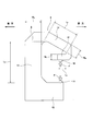
- the schematic side view of the press apparatus regarding 1st Embodiment of this invention The schematic side view which shows the press apparatus regarding 1st Embodiment of this invention in the state before and behind that a C-shaped flame
- the press device 8 of this example is used in a state where it is placed on the floor surface of a factory or the like, and has a C-shaped frame 9, a fixed die (upper action portion, second action point) 10, and a movable die. (Lower action part, first action point) 11.
- the C-shaped frame 9 is made of metal, and the lower frame 12, the intermediate frame 13, the first upper frame 14, and the second upper frame 15 are opened at the front side in the front-rear direction and the both sides in the left-right direction. It is configured by combining with a substantially C shape.
- the lower frame 12 is placed on the floor surface of a factory or the like, and is arranged in the front-rear direction.
- the intermediate frame 13 is arranged in the vertical direction, and the lower end portion is coupled to the rear end portion of the lower frame 12.
- the first upper frame 14 is disposed in the front-rear direction, the rear end portion is coupled to the upper end portion of the intermediate frame 13, and the front end portion is located below the rear end portion. In other words, the first upper frame 14 is inclined downward in the direction from the rear end portion toward the front end portion.
- the second upper frame 15 is disposed in the front-rear direction, and the front end is coupled to the front end of the first upper frame 14.
- the length of the second upper frame 15 is sufficiently smaller than the length of the first upper frame 14.
- such a C-shaped frame 9 can be formed by joining and fixing a plurality of parts to each other, and can also be formed integrally as a whole.
- the fixed mold 10 is supported and fixed to the lower surface of the rear end portion of the second upper frame 15.
- the movable mold 11 is supported so as to be movable in the vertical direction with respect to the front end portion of the lower frame 12 in a state of being arranged below the fixed mold 10. Specifically, the movable mold 11 is supported by a hydraulic or electric cylinder (not shown) assembled to the lower frame 12 so as to be movable in the vertical direction. In this state, the central axes of the fixed mold 10 and the movable mold 11 are located on the same imaginary line extending in the vertical direction.
- the movable die 11 is retracted downward with respect to the fixed die 10 and the fixed die 10 is also retracted.
- the movable mold 11 is moved upward toward the fixed mold 10 while the workpiece is set on the movable mold 11.
- a predetermined pressing process such as shearing, bending, drawing, forging or the like is performed on the workpiece between the fixed mold 10 and the movable mold 11.
- the processing reaction force F from the workpiece is C via the fixed mold 10 and the movable mold 11 (and cylinder). Join the shape frame 9.
- the C-shaped frame 9 undergoes elastic deformation of the opening as shown by a two-dot chain line in FIG.
- the intermediate frame 13 rotates or tilts counterclockwise (+ direction) on one side with respect to the left and right axis Z 1 with respect to the lower frame 12.
- the upper frame 14 rotates or tilts counterclockwise (+ direction) about the horizontal axis Z 2 with respect to the intermediate frame 13, and the second upper frame 15 moves left and right with respect to the first upper frame 14.
- the C-shaped frame 9 is elastically deformed so as to rotate, that is, tilt in the clockwise direction ( ⁇ direction) on the other side about the direction axis Z 3 .
- the processing reaction force F acting on the lower frame 12 is supported by the floor surface, the posture of the lower frame 12 does not change.
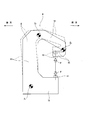
- FIG. 3 schematically shows the posture change of the C-shaped frame 9 at this time, that is, a skeletal model ignoring the elastic bending deformation generated in each of the frames 13 to 15. .
- the C-shaped frame 9 indicates a state before elastic deformation by a solid line and a state after elastic deformation by a two-dot chain line.
- the frame 9 has a first action point (11) corresponding to the movable mold (lower action part) 11 and a second action point (10) corresponding to the fixed mold (upper action part) 10.
- the first action point (11) and the second action point (10) are arranged opposite to each other, and a reaction force during processing (for example, press working) is applied to the first action point (11) and the second action point (10). Acts substantially simultaneously.
- a gap is provided between the first action point (11) and the second action point (10) in at least the first direction (for example, the vertical direction).
- the frame 9 has a continuous element that is continuous between the first action point (11) and the second action point (10), and the continuous element has at least a first direction and a second direction that intersects the first direction ( For example, it extends in the vertical direction).
- the continuous elements include a first element (12) corresponding to the lower frame 12, a second element (13) corresponding to the intermediate frame 13, a third element (14) corresponding to the upper frame 14, and the upper frame 15. And a corresponding fourth element (15).
- Continuous elements of the frame 9, in order toward the first working point (11) from the second working point (10) has a first position Z 1, and a second position Z 2, and a third position Z 3.
- a first position Z 1 is disposed between the first element (12) and the second element (13).
- Second position Z 2 is disposed between the second element (13) and the third element (14).
- Third position Z 3 is disposed between the third element (14) and the fourth element (15).
- the first element (12) is arranged between the first working point (11) and the first position Z 1
- first position Z 1 and a second position Z 2 the second element (13) is arranged between the second position Z 2 and which third element (14) is disposed between the third position Z 3, the third position Z 3 and second working point (10)
- the fourth element 15 is arranged between the two. In the first direction, between the first position Z 1 and second position Z 2, the third position Z 3 and second working point (10) is arranged.
- the second working point (10) is disposed between the second position Z 2 and third location Z 3.
- the second position Z 2 , the third position Z 3 , and the second action point (10) are arranged above the first action point (11) and the first position Z 1 .
- a second position Z 2 are disposed above.
- the second action point (10) is disposed between the second position Z 2 and third location Z 3.
- the angle ( ⁇ ) between the connecting lines changes ( ⁇ 1 ⁇ ⁇ 2).
- the central axis of the fixed mold 10 is also counterclockwise by the same angle ( ⁇ 2 ⁇ 1). Tilt around (+ direction).
- the central axis of the fixed mold 10 is also rotated counterclockwise by the same angle ( ⁇ 2 ⁇ 1). Tilt in the + direction).
- the central axis of the fixed mold 10 is also rotated clockwise by the same angle ( ⁇ 1 ⁇ 2) ( ⁇ Tilt in the direction).
- the intermediate frame 13 when the intermediate frame 13 is tilted counterclockwise (+ direction) with respect to the lower frame 12 as described above, the upper end of the intermediate frame 13 is It is displaced backward by a distance ⁇ L1sin ( ⁇ 2- ⁇ 1) ⁇ corresponding to the length ⁇ L1 (FIG. 3) ⁇ and the tilt angle ( ⁇ 2- ⁇ 1). Accordingly, the fixed mold 10 is also displaced backward by the same distance.
- the first upper frame 14 since the front end of the first upper frame 14 is located below the rear end, the first upper frame 14 rotates counterclockwise with respect to the intermediate frame 13 as described above ( When tilted in the + direction), the front end portion of the first upper frame 14 depends on the length ⁇ L2 (FIG.
- the fixed mold 10 is also displaced forward by the same distance.
- the length of the second upper frame 15 is made sufficiently shorter than the length of the first upper frame 14, or the second upper frame 15 is nearly parallel to the front-rear direction. Because of the arrangement, even if the second upper frame 15 is tilted clockwise ( ⁇ direction) with respect to the first upper frame 14 as described above, the fixed mold 10 generates a very small displacement in the front-rear direction. Absent.
- the axial displacement between the fixed mold 10 and the movable mold 11 (center between the fixed mold 10 and the movable mold 11) that occurs when the workpiece is pressed.
- the inclination of the shafts and the relative displacement in the front-rear direction between the fixed mold 10 and the movable mold 11) can be effectively suppressed.
- by adjusting the length and rigidity balance of each part constituting the C-shaped frame 9, as shown in FIG. It is also possible to make almost no axial deviation between the movable mold 11 and the movable mold 11.
- the fixed mold 10 is fixed while allowing the fixed mold 10 to be displaced upward as the elastic deformation amount of the C-shaped frame 9 increases as the machining reaction force increases. It is possible to prevent an axial deviation between the mold 10 and the movable mold 11 from occurring. Therefore, in the case of this example, it is possible to improve the processing accuracy of the workpiece and to extend the lifetime of the fixed mold 10 and the movable mold 11.
- the fixed mold 10 is supported and fixed to the second upper frame 15 and the movable mold 11 is supported to the lower frame 12 so as to be movable in the vertical direction.
- the C-shaped frame 9 and the press device 8 have been described using a configuration in which they are installed in the vertical direction.
- the direction in which the C-shaped frame 9 and the press device 8 are installed is not necessarily in the vertical direction, and can be installed in any direction.
- the frame structure of the above-described embodiment is used in a processing apparatus including a friction stir welding apparatus as disclosed in, for example, Japanese Patent Application Laid-Open No. 2014-18850. Further, the frame structure of the above-described embodiment is used for manufacturing parts including, for example, mechanical parts, electric parts and the like. In particular, the frame structure of the above-described embodiment is used for manufacturing bearing parts. For example, the frame structure of the above-described embodiment is used for manufacturing a bearing component including a rolling bearing as disclosed in Japanese Patent Application Laid-Open No. 2014-101896. Further, for example, the frame structure of the above-described embodiment is used for manufacturing a vehicle or a machine.
- the frame structure of the above-described embodiment may be used for manufacturing a vehicle or a machine including a rolling bearing.
- vehicle, machine, or the like to be manufactured may be any power other than human power for operating the vehicle, machine, etc., regardless of the type of power, or the power may be human power.
- the material of the C-shaped frame 9 is SS400 (JIS G 3101 rolled steel for general structure), and the C-shaped frame 9
- the thickness dimension T in the left-right direction is 35 mm
- the length dimension L A in FIG. 1 of the intermediate frame 13 is 370 mm
- the width dimension W A in FIG. in Figure 1 of the frame 14 the length L B and 130 mm
- the width W B of FIG. 1 of the first upper frame 14 and 51 mm in FIG. 1 of the second upper frame 15
- the length dimension L C is set to 70 mm
- the pressing force (processing reaction force F) applied to the workpiece is set to 4000 N, for example. it can.
- the material of the C-shaped frame 9 and the thickness dimension T in the left-right direction are irrelevant to the axial misalignment between the fixed mold 10 and the movable mold 11 that occurs when a pressing force is applied to the workpiece. This affects the amount of relative displacement between the fixed mold 10 and the movable mold 11 in the axial direction (pressing force direction).
- the axial deviation between the fixed mold 10 and the movable mold 11 that occurs when, for example, a pressing force of 4000 N is applied to the work piece becomes extremely small. It becomes small enough to be neglected in the pressing process.
Landscapes
- Engineering & Computer Science (AREA)
- Mechanical Engineering (AREA)
- Presses And Accessory Devices Thereof (AREA)
- Forging (AREA)
Priority Applications (4)
| Application Number | Priority Date | Filing Date | Title |
|---|---|---|---|
| US16/087,927 US10611114B2 (en) | 2017-02-06 | 2017-08-30 | Frame structure, processing apparatus, method of manufacturing components, method of manufacturing rolling bearing, method of manufacturing vehicle, method of manufacturing machine and press apparatus |
| JP2018512228A JP6380708B1 (ja) | 2017-02-06 | 2017-08-30 | フレーム構造、加工装置、部品の製造方法、転がり軸受の製造方法、車両の製造方法、機械の製造方法及びプレス装置 |
| CN201780084209.2A CN110198831B (zh) | 2017-02-06 | 2017-08-30 | 框架构造、加工装置、部件的制造方法、滚动轴承的制造方法、车辆的制造方法、机械的制造方法以及冲压装置 |
| EP17895047.3A EP3578351B1 (en) | 2017-02-06 | 2017-08-30 | Frame structure, method for producing component, method for producing rolling bearing, method for producing vehicle and method for producing machine |
Applications Claiming Priority (2)
| Application Number | Priority Date | Filing Date | Title |
|---|---|---|---|
| JP2017019364 | 2017-02-06 | ||
| JP2017-019364 | 2017-02-06 |
Publications (1)
| Publication Number | Publication Date |
|---|---|
| WO2018142654A1 true WO2018142654A1 (ja) | 2018-08-09 |
Family
ID=63039588
Family Applications (1)
| Application Number | Title | Priority Date | Filing Date |
|---|---|---|---|
| PCT/JP2017/031129 Ceased WO2018142654A1 (ja) | 2017-02-06 | 2017-08-30 | フレーム構造、加工装置、部品の製造方法、転がり軸受の製造方法、車両の製造方法、機械の製造方法及びプレス装置 |
Country Status (5)
| Country | Link |
|---|---|
| US (1) | US10611114B2 (enExample) |
| EP (1) | EP3578351B1 (enExample) |
| JP (2) | JP6380708B1 (enExample) |
| CN (1) | CN110198831B (enExample) |
| WO (1) | WO2018142654A1 (enExample) |
Families Citing this family (1)
| Publication number | Priority date | Publication date | Assignee | Title |
|---|---|---|---|---|
| EP4074432A1 (de) * | 2021-04-15 | 2022-10-19 | Bystronic Laser AG | Biegemaschine zur biegung von werkstücken, insbesondere abkantpresse |
Citations (8)
| Publication number | Priority date | Publication date | Assignee | Title |
|---|---|---|---|---|
| JPS5916800U (ja) * | 1982-07-20 | 1984-02-01 | 株式会社小松製作所 | プレス機械 |
| JPS6233100A (ja) * | 1986-04-05 | 1987-02-13 | Aida Eng Ltd | ギャップフレームプレス |
| US5633024A (en) * | 1995-12-07 | 1997-05-27 | Ziv-Av; Amir | Clamping assembly for injection molding apparatus |
| JP2001025900A (ja) | 1999-07-12 | 2001-01-30 | Aida Eng Ltd | Cフレームプレスのギブ補正装置 |
| JP2014018850A (ja) | 2012-07-23 | 2014-02-03 | Nsk Ltd | 摩擦攪拌接合装置 |
| JP2014101896A (ja) | 2012-11-16 | 2014-06-05 | Nsk Ltd | 転がり軸受 |
| JP2015077616A (ja) * | 2013-10-17 | 2015-04-23 | 日本精工株式会社 | 車輪支持用転がり軸受ユニットの製造方法 |
| JP2017019364A (ja) | 2015-07-09 | 2017-01-26 | 本田技研工業株式会社 | 車両用シートアセンブリ |
Family Cites Families (12)
| Publication number | Priority date | Publication date | Assignee | Title |
|---|---|---|---|---|
| FR528452A (fr) * | 1920-06-04 | 1921-11-12 | Pierre Plana | Perfectionnement aux presses à col de cygne |
| JPS5095869A (enExample) * | 1973-12-27 | 1975-07-30 | ||
| SU1224181A1 (ru) * | 1984-10-05 | 1986-04-15 | Предприятие П/Я А-7555 | Вертикальный пресс |
| JPS61154798A (ja) * | 1984-12-28 | 1986-07-14 | Koshin Giken:Kk | 片持プレス装置 |
| NL8801799A (nl) * | 1988-07-14 | 1990-02-01 | Brouwer & Co Holding | Gereedschapsmachine met c-vormig frame. |
| JP2894503B2 (ja) * | 1990-02-28 | 1999-05-24 | 株式会社アマダ | パンチプレス |
| US5062290A (en) * | 1990-06-25 | 1991-11-05 | Burndy Corporation | Hydraulic crimping press for electrical connectors |
| DE19501469C2 (de) * | 1995-01-19 | 1998-03-26 | Hemscheidt Maschtech Schwerin | Holmlose Formschließeinrichtung |
| US6072583A (en) * | 1996-12-06 | 2000-06-06 | General Electro Mechanical Corp. | Apparatus and method for detecting mis-oriented fasteners |
| ES2244749T3 (es) * | 2001-03-16 | 2005-12-16 | Bystronic Laser Ag | Procedimiento de regulacion de la carrera de una prensa plegadora. |
| US7305755B2 (en) * | 2003-12-18 | 2007-12-11 | Heiko Schmidt | Processing tong |
| DE102005043211A1 (de) * | 2005-09-09 | 2007-03-15 | Newfrey Llc, Newark | Fügevorrichtung zum umformtechnischen Fügen |
-
2017
- 2017-08-30 CN CN201780084209.2A patent/CN110198831B/zh active Active
- 2017-08-30 JP JP2018512228A patent/JP6380708B1/ja active Active
- 2017-08-30 WO PCT/JP2017/031129 patent/WO2018142654A1/ja not_active Ceased
- 2017-08-30 US US16/087,927 patent/US10611114B2/en active Active
- 2017-08-30 EP EP17895047.3A patent/EP3578351B1/en active Active
-
2018
- 2018-07-20 JP JP2018136270A patent/JP7020327B2/ja active Active
Patent Citations (8)
| Publication number | Priority date | Publication date | Assignee | Title |
|---|---|---|---|---|
| JPS5916800U (ja) * | 1982-07-20 | 1984-02-01 | 株式会社小松製作所 | プレス機械 |
| JPS6233100A (ja) * | 1986-04-05 | 1987-02-13 | Aida Eng Ltd | ギャップフレームプレス |
| US5633024A (en) * | 1995-12-07 | 1997-05-27 | Ziv-Av; Amir | Clamping assembly for injection molding apparatus |
| JP2001025900A (ja) | 1999-07-12 | 2001-01-30 | Aida Eng Ltd | Cフレームプレスのギブ補正装置 |
| JP2014018850A (ja) | 2012-07-23 | 2014-02-03 | Nsk Ltd | 摩擦攪拌接合装置 |
| JP2014101896A (ja) | 2012-11-16 | 2014-06-05 | Nsk Ltd | 転がり軸受 |
| JP2015077616A (ja) * | 2013-10-17 | 2015-04-23 | 日本精工株式会社 | 車輪支持用転がり軸受ユニットの製造方法 |
| JP2017019364A (ja) | 2015-07-09 | 2017-01-26 | 本田技研工業株式会社 | 車両用シートアセンブリ |
Non-Patent Citations (1)
| Title |
|---|
| See also references of EP3578351A4 |
Also Published As
| Publication number | Publication date |
|---|---|
| JP6380708B1 (ja) | 2018-08-29 |
| CN110198831B (zh) | 2022-02-22 |
| EP3578351A1 (en) | 2019-12-11 |
| US20190084263A1 (en) | 2019-03-21 |
| EP3578351A4 (en) | 2020-12-16 |
| JP2018158387A (ja) | 2018-10-11 |
| CN110198831A (zh) | 2019-09-03 |
| JPWO2018142654A1 (ja) | 2019-02-14 |
| JP7020327B2 (ja) | 2022-02-16 |
| EP3578351B1 (en) | 2024-02-28 |
| US10611114B2 (en) | 2020-04-07 |
Similar Documents
| Publication | Publication Date | Title |
|---|---|---|
| US9187875B2 (en) | Arm for construction machine | |
| JP2020040582A (ja) | サスペンションサポートブラケットおよびサスペンションサポートブラケットの製造方法 | |
| JP6380708B1 (ja) | フレーム構造、加工装置、部品の製造方法、転がり軸受の製造方法、車両の製造方法、機械の製造方法及びプレス装置 | |
| JP6189249B2 (ja) | 乗物用シート | |
| JP2020040444A (ja) | 車体のクロスメンバおよびクロスメンバの製造方法 | |
| CN114435475A (zh) | 车辆用副车架 | |
| CN114435286A (zh) | 车辆用副车架 | |
| JP5891876B2 (ja) | ステアリング装置 | |
| JP2019025529A (ja) | ローラヘミング加工方法 | |
| JP2016060311A (ja) | サブフレーム構造 | |
| JPWO2020116350A1 (ja) | ステアリング装置 | |
| KR102412348B1 (ko) | 작업 기계의 작업 암 | |
| JP2009214124A (ja) | スライド傾き軽減方法及びスライド傾き軽減装置 | |
| JP5941272B2 (ja) | 入口ローラーガイド | |
| JP2002001599A (ja) | プレス機械 | |
| JP3953010B2 (ja) | スライドドア装置 | |
| JP6897024B2 (ja) | 接合方法 | |
| JP3843098B2 (ja) | 送り系構造及びこれを備えた工作機械 | |
| JP7132879B2 (ja) | 金型プレス装置及び金型プレス方法 | |
| JP4141690B2 (ja) | 曲げ加工機 | |
| JP7627622B2 (ja) | 車両用シート装置 | |
| JP6737848B2 (ja) | 工作機械 | |
| JP6098745B2 (ja) | ステアリング装置 | |
| US10967713B2 (en) | Vehicle side door | |
| JP2004098086A (ja) | 3点駆動プレス機械 |
Legal Events
| Date | Code | Title | Description |
|---|---|---|---|
| ENP | Entry into the national phase |
Ref document number: 2018512228 Country of ref document: JP Kind code of ref document: A |
|
| 121 | Ep: the epo has been informed by wipo that ep was designated in this application |
Ref document number: 17895047 Country of ref document: EP Kind code of ref document: A1 |
|
| NENP | Non-entry into the national phase |
Ref country code: DE |
|
| WWE | Wipo information: entry into national phase |
Ref document number: 2017895047 Country of ref document: EP |