WO2018135260A1 - 無人搬送車 - Google Patents
無人搬送車 Download PDFInfo
- Publication number
- WO2018135260A1 WO2018135260A1 PCT/JP2017/046727 JP2017046727W WO2018135260A1 WO 2018135260 A1 WO2018135260 A1 WO 2018135260A1 JP 2017046727 W JP2017046727 W JP 2017046727W WO 2018135260 A1 WO2018135260 A1 WO 2018135260A1
- Authority
- WO
- WIPO (PCT)
- Prior art keywords
- guided vehicle
- movable body
- vehicle
- automatic guided
- vehicle body
- Prior art date
- Legal status (The legal status is an assumption and is not a legal conclusion. Google has not performed a legal analysis and makes no representation as to the accuracy of the status listed.)
- Ceased
Links
Images






Classifications
-
- B—PERFORMING OPERATIONS; TRANSPORTING
- B65—CONVEYING; PACKING; STORING; HANDLING THIN OR FILAMENTARY MATERIAL
- B65G—TRANSPORT OR STORAGE DEVICES, e.g. CONVEYORS FOR LOADING OR TIPPING, SHOP CONVEYOR SYSTEMS OR PNEUMATIC TUBE CONVEYORS
- B65G1/00—Storing articles, individually or in orderly arrangement, in warehouses or magazines
-
- B—PERFORMING OPERATIONS; TRANSPORTING
- B65—CONVEYING; PACKING; STORING; HANDLING THIN OR FILAMENTARY MATERIAL
- B65G—TRANSPORT OR STORAGE DEVICES, e.g. CONVEYORS FOR LOADING OR TIPPING, SHOP CONVEYOR SYSTEMS OR PNEUMATIC TUBE CONVEYORS
- B65G63/00—Transferring or trans-shipping at storage areas, railway yards or harbours or in opening mining cuts; Marshalling yard installations
-
- G—PHYSICS
- G05—CONTROLLING; REGULATING
- G05D—SYSTEMS FOR CONTROLLING OR REGULATING NON-ELECTRIC VARIABLES
- G05D1/00—Control of position, course, altitude or attitude of land, water, air or space vehicles, e.g. using automatic pilots
- G05D1/02—Control of position or course in two dimensions
Definitions
- This invention relates to an automatic guided vehicle.
- the automatic guided vehicle that can mount the container is a large automatic guided vehicle (for example, the total length is 15.0 m, the width is 3.0 m, and the height is 2.0 m or more).
- container transportation by high-speed traveling is required to improve the efficiency of container transportation, so the maximum speed may be improved to about 25 km / h.
- an emergency stop button as an emergency stop means is provided in front of and behind the vehicle body side of the automatic guided vehicle.
- the power source of the drive unit can be directly shut off without using a control unit that controls the drive unit of the automatic guided vehicle.
- This type of emergency stop means is a condition required for automatic guided vehicles according to related laws and regulations, JIS standards, and the like.
- Patent Document 1 discloses a submersible automatic guided vehicle that is submerged under a wagon and conveys the wagon in that state.
- An emergency stop button and a bumper are provided at the front and rear ends of the wagon. For example, when an emergency stop button is pressed, stop control means provided in the automatic guided vehicle causes the automatic guided vehicle to emergency stop.
- the automatic guided vehicle that transports the container is significantly larger than the automatic guided vehicle disclosed in Patent Document 1, and an operator approaches the traveling vehicle body for an emergency stop of the automatic guided vehicle. It is difficult to touch the emergency stop button directly. Moreover, the greater the speed of the large automated guided vehicle, the greater the difficulty of directly touching the emergency stop button.
- the present invention has been made in view of the above problems, and an object of the present invention is to provide an automatic guided vehicle capable of making an emergency stop by touching the automatic guided vehicle indirectly at a position away from the automatic guided vehicle. On offer.
- the present invention provides a vehicle body, a travel drive unit provided in the vehicle body, a control unit that is mounted on the vehicle body and controls the travel drive unit, and the control unit.
- the emergency stop device is provided on a side surface of the vehicle body so as to be displaceable and can be locked.
- a movable body comprising: a detector that detects displacement of the movable body; and a switch that blocks power supply to the driving unit based on detection of displacement of the movable body by the detector. It is characterized by having.
- the detector when an operator displaces the movable body with respect to the vehicle body by locking the locking member to the locked portion at a position away from the traveling automatic guided vehicle, the detector is moved to the movable body. Detect displacement.
- the switch interrupts the power supply to the driving unit for travel, so that the automatic guided vehicle stops without going through the control unit. Therefore, when the automatic guided vehicle is brought to an emergency stop, the movable body is indirectly displaced using a locking tool, so that the automatic guided vehicle can be moved away from the automatic guided vehicle without touching the automatic guided vehicle directly. Can be stopped.
- the movable body extends along a side surface of the vehicle body and is capable of being displaced with respect to the vehicle body, and is fixed to the long member, It is good also as a structure which has a to-be-latched member provided with the part.
- the movable body since the movable body has a long member that is displaced with respect to the vehicle body, the movable body is provided in the front-rear direction over the side surface of the vehicle body. Therefore, it becomes possible to provide a locked member having a locked portion over the longitudinal direction of the long member, and in particular, when a plurality of locked members are provided, it is easier to lock the locking tool to the movable body. It becomes.
- the movable body may be configured to be displaceable in the front-rear direction of the vehicle body. Since the movable body can be displaced in the front-rear direction, the movable body is not displaced in the front-rear direction even if vertical vibrations occur in the automatic guided vehicle during loading. For this reason, the automatic guided vehicle is not emergency-stopped due to a malfunction caused by vibration during loading.
- the movable body may be a flexible string-like member extending along the side surface of the vehicle body.
- the flexible string-like member extending on the side surface of the vehicle body can be displaced with respect to the vehicle body and has a function as a locked portion. For this reason, by locking the locking tool to the string-like member, the string-like member can be displaced with respect to the vehicle body, and the automatic guided vehicle can be emergency-stopped.
- an automatic guided vehicle that enables an emergency stop by indirectly touching the automatic guided vehicle at a position away from the automatic guided vehicle.
- (A) is a principal part side view of the movable body which concerns on another example 1
- (b) is a principal part side view of the movable body and detector which concerns on another example 2
- the automatic guided vehicle for containers of this embodiment receives a container cargo handling between a ship and a container yard at a container terminal as a port facility and transports the container.
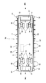
- the vehicle body 11 of the containerless guided vehicle 10 includes a loading platform 12 that supports a container C as a load.
- a pair of left and right front wheels 13 are provided on the lower front side of the vehicle body 11, and a pair of left and right rear wheels 14 are provided on the lower rear side of the vehicle body 11.
- the loading platform 12 can support a 40 ft (feet) standard container (hereinafter referred to as “40 ft container”) C.
- 40 ft container standard container
- the loading platform 12 can support two 20 ft containers in the front and rear.
- the overall length of the vehicle body 11 is a length that matches the overall length of the 40 ft container C.
- stoppers 15 that regulate the displacement in the width direction of the 40 ft container C with respect to the loading platform 12.
- stoppers 16 are provided at the front portion and the rear portion of the vehicle body 11 to regulate the positional displacement in the length direction of the 40 ft container C mounted on the loading platform 12.
- the stoppers 16 provided at the front part and the rear part of the vehicle body 11 can correspond to a 20 ft container.
- a turning support portion 17 that is turnable in the horizontal direction with respect to the vehicle body 11 is provided.
- a shaft case 18 that houses an axle (not shown) and a differential mechanism (not shown) is connected to the lower end of the turning support portion 17.
- Tires 19 are respectively attached to both ends of the axle, and the front wheels 13 and the rear wheels 14 have a double tire structure including two tires 19.
- the shaft case 18 is provided with an electric motor 20 for traveling.
- the electric motor 20 corresponds to a traveling drive unit.
- the electric motor 20 is fixed to the shaft case 18 so that the longitudinal direction of the electric motor 20 is substantially horizontal between the two tires 19.
- the rotational force of the electric motor 20 is transmitted to the axle via the differential mechanism. Accordingly, the driving force for traveling is transmitted from the corresponding electric motor 20 to all the wheels (front wheel 13 and rear wheel 14).
- a servo motor is used as the electric motor 20.
- a steering mechanism 21 is connected to the upper part of each turning support portion 17.
- the steering mechanism 21 includes a steering electric motor and a reduction gear for turning the turning support portion 17. Therefore, the front wheel 13 and the rear wheel 14 can be steered independently of each other by the operation of the steering mechanism 21.
- the maximum steering angle of the front wheels 13 and the rear wheels 14 is set to 90 degrees or more in the right direction and 90 degrees or more in the left direction when the steering angle during straight traveling is 0 degree. Accordingly, the steering angle at which the front wheel 13 and the rear wheel 14 can be steered is 0 to 90 degrees or more in the right direction and 0 to 90 degrees or more in the left direction. That is, the steering angle at which the front wheels 13 and the rear wheels 14 can be steered is set to 90 degrees or more in the left-right direction with respect to the steering angle 0 degrees during straight traveling.
- the vehicle body 11 is equipped with a controller 22 for controlling each part of the automatic guided vehicle 10 for containers.
- the controller 22 includes an arithmetic processing unit 23, a storage unit 24, and a communication unit 25.
- the arithmetic processing unit 23 executes various programs and performs various data processing.
- the storage unit 24 executes various programs and stores various data.
- the communication unit 25 communicates with an upper computer (not shown) installed on the ground side.
- the automatic guided vehicle 10 for a container travels at a container terminal or stops at a predetermined position based on a command from a host computer.
- the host computer grasps the operation status of the automatic guided vehicle 10 for containers at the container terminal and grasps the cargo handling status of the container terminal.
- the controller 22 is connected to a motor driver 26 that controls driving of each electric motor 20 and has a function of instructing the motor driver 26.
- the motor driver 26 supplies the electric motor 20 with electric power according to the command from the controller 22. Therefore, the controller 22 can perform vehicle speed control by drive control of the electric motor 20 by instructing the motor driver 26.
- the controller 22 sends a command for acceleration or deceleration to the motor driver 26 in addition to a command to the motor driver 26 for high speed travel (25 km / h) and a command for low speed travel (0.5 km / h). Can be communicated to.
- the controller 22 corresponds to a control unit.
- the controller 22 is connected to each steering mechanism 21, and each steering mechanism 21 steers the corresponding wheel based on a command from the controller 22.
- Each wheel is steered independently from each other by a corresponding steering mechanism 21.
- the controller 22 controls each steering mechanism 21 so that the steering angles of the front wheels 13 and the rear wheels 14 are 0 degrees.
- the controller 22 controls each steering mechanism 21 so as to have a steering angle necessary to correspond to the curved route of the front wheels 13 and the rear wheels 14.
- each steering mechanism 21 is controlled so that the vehicle travels obliquely without changing the direction of the vehicle body 11 or travels in the width direction of the vehicle body 11 without changing the direction of the vehicle body 11. .
- a position detection sensor 27 for reading a marker M embedded in the road surface is provided at the front and rear of the bottom of the vehicle body 11.
- the position detection sensor 27 detects the position by reading the marker M.
- the marker M of this embodiment is a magnetic marker, and ID information (position information of X and Y coordinates) for each marker is held in these markers M.
- ID information position information of X and Y coordinates
- the position detection sensor 27 is connected to the controller 22.
- the controller 22 recognizes the position of the automatic guided vehicle 10 for a container based on the detection signal of the position detection sensor 27.
- the automatic guided vehicle 10 for containers of this embodiment is provided with an emergency stop device for making an emergency stop of the automatic guided vehicle 10 for traveling.
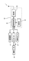
- the emergency stop device includes a detector 31 provided near the front end and the rear end of the left and right side surfaces of the vehicle body 11, a movable body 32 connected to the detector 31 and provided to be displaceable, and a movable body formed by the detector 31. And an electromagnetic switch 33 that cuts off the power supply to the electric motor 20 based on the detection of 32.
- the detector 31 is for detecting the displacement of the movable body 32 with respect to the vehicle body 11. As shown in FIG. 5, the detector 31 includes a detection unit 35, a detection arm unit 36, and a cover member 37. A proximal end portion of a detection arm unit 36 is connected to the detection unit 35. The detection arm portion 36 can tilt back and forth with the base end portion as a fulcrum. The distal end portion of the detection arm portion 36 is connected to the end portion of the movable body 32.
- the detection unit 35 is a switch that switches from ON to OFF when the tilt of the detection arm unit 36 is detected.
- the detector 31 is biased to return the detection arm unit 36 to the ON position (neutral position) even when the detection arm unit 36 is tilted to a position (switching position) where the detection unit 35 is switched from ON to OFF. Means (not shown) are provided. A coil spring is used as the biasing means.
- the cover member 37 is a member that covers the outer periphery of the detection unit 35.
- the movable body 32 has an attachment portion 38 connected to the detection arm portion 36 and a substantially U-shaped locked portion 39 formed integrally with the attachment portion 38.
- the attachment portion 38 is fixed to the distal end portion of the detection arm portion 36 so that the longitudinal direction is up and down. It is being fixed to the attaching part 38 so that a pair of edge part of the to-be-latched part 39 may become up and down. Therefore, as shown in FIG. 3, the movable body 32 projects outward in the width direction of the vehicle body 11.
- the locked portion 39 is a portion in the movable body 32 where a locking tool 47 described later is easily locked.
- the movable body 32 can be displaced by being tilted back and forth integrally with the detection arm portion 36 by receiving a load in the front-rear direction.
- the movable body 32 is connected to each detector 31 provided on the vehicle body 11.
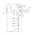
- the electromagnetic switch 33 is a contactor including a contact 41 that can be opened and closed and an exciting coil 42 that opens and closes the contact 41.
- the electromagnetic switch 33 according to the present embodiment is provided between the in-vehicle battery 43 and the motor driver 26 in the power circuit.
- the electromagnetic switch 33 closes the contact 41 and energizes the electric motor 20 from the in-vehicle battery 43.
- the electromagnetic switch 33 opens the contact 41 and interrupts energization from the in-vehicle battery 43 to the electric motor 20.
- the detector 31 is connected in series with the exciting coil 42. In the present embodiment, since four detectors 31 are provided, these detectors 31 are connected in series.
- the power circuit shown in FIG. 6 includes switches 44 and 45 connected in parallel between the exciting coil 42 and the detector 31.
- An exciting coil 46 for opening and closing the switch 44 is connected in series with the detector 31.
- the switch 44 is closed by exciting the exciting coil 46. Therefore, the switch 44 and the exciting coil 46 constitute a relay.
- the switch 44 remains closed unless the excitation coil 46 is de-energized, but once the excitation coil 46 is de-energized, it remains open. That is, once the detection unit 35 of the detector 31 is turned off, the switch 44 is not closed even if the detection unit 35 is turned on. That is, the switch 44 and the exciting coil 46 constitute a self-holding circuit.
- the switch 45 is a normally open switch, and is a return switch for returning the automatic guided vehicle 10 for a container from an emergency stop state to a travelable state.
- the switch 44 In the state where the excitation of the excitation coil 46 is released, the switch 44 is open. However, when the switch 45 is operated and closed, the excitation coil 46 is excited and the switch 44 is closed and is energized. Further, since the exciting coil 42 is also excited by energization, the contact 41 is closed, the electromagnetic switch 33 is energized, and the containerless guided vehicle 10 is returned to a travelable state.
- the switch 45 is a button that is provided on the vehicle body 11 and can be directly operated by an operator.
- the locking tool 47 is a boat hook used to draw a small boat, and is always provided at the container terminal.
- the container automatic guided vehicle 10 is used as a locking tool 47 for making an emergency stop.
- the locking tool 47 includes a telescopic pole portion 48 and a hook portion 49 attached to the tip end portion of the pole portion 48.
- the locking member 47 When the pole portion 48 is extended, the locking member 47 has a length of 2 m or more.
- the hook portion 49 is formed in a hook shape that can be locked to the locked portion 39 of the movable body 32.
- the end of the locking tool 47 opposite to the tip provided with the hook portion 49 is a part that is gripped by the operator.
- the containerless guided vehicle 10 travels on the travel route while checking the current position while reading the marker M on the travel route.
- the exciting coil 42 is excited and the electromagnetic switch 33 is in an energized state.
- the exciting coil 46 is energized and the switch 44 is closed and energized.
- the electric power of the vehicle-mounted battery 43 is supplied to the electric motor 20 via the electromagnetic switch 33 and the motor driver 26.
- the operator locks the hook part 49 of the extended locking tool 47 to the locked part 39 of the movable body 32.
- the movable body 32 is tilted and displaced with respect to the vehicle body 11.
- the detection arm unit 36 is tilted from the ON position (neutral position) to the OFF position (switching position) by using the locking tool 47, the operator releases the locking tool 47 and the containerless guided vehicle 10 for containers. You should keep away from.
- the detection part 35 When the detection arm part 36 is tilted to the switching position, the detection part 35 is turned off and the excitation of the excitation coils 42 and 46 is canceled.
- the excitation coil 42 When the excitation coil 42 is de-energized, the contact 41 of the electromagnetic switch 33 is opened, the current supply is cut off, and the electric motor 20 stops. Due to the stop of the electric motor 20, the containerless guided vehicle 10 is brought to an emergency stop.
- the switch 44 is opened. For this reason, the exciting coils 42 and 46 are excited even when the detecting arm 36 returns from the switching position to the neutral position by the urging means for returning the detecting arm 36 to the neutral position.
- the detection unit 35 is not turned on. In this way, by operating the emergency stop device using the locking tool 47, the energization to the electric motor 20 is directly cut off without going through the controller 22, and the containerless guided vehicle 10 is emergency stopped.
- the switch 45 may be closed by an operator's operation. By closing the switch 45, the exciting coils 42 and 46 are excited, the contact 41 of the electromagnetic switch 33 is closed, and the switch 44 is closed. By closing the switch 44, it is possible to continue exciting the exciting coils 42 and 46 even when the switch 45 is opened. For this reason, the electric power of the vehicle-mounted battery 43 can be supplied to the electric motor 20 via the electromagnetic switch 33 and the motor driver 26.
- the container automatic guided vehicle 10 has the following effects. (1) When a worker displaces the movable body 32 with respect to the vehicle body 11 by locking the locking member 47 on the locked portion 39 at a position away from the traveling containerless guided vehicle 10 during traveling, The detector 31 detects the displacement of the movable body 32. When the detector 31 detects the displacement of the movable body 32, the electromagnetic switch 33 cuts off the power supply to the electric motor 20, so that the container-less automated guided vehicle 10 comes to an emergency stop without using the controller 22.
- the movable body 32 is indirectly displaced by using the locking tool 47 so that the container-type guided vehicle 10 is separated from the container-type guided vehicle 10 at a position away from the container-less guided vehicle 10. 10 can be emergency stopped. Even when the large container automatic guided vehicle 10 is traveling at high speed, the emergency stop of the container automatic guided vehicle 10 can be easily performed.
- the locking tool 47 is easily locked to the movable body 32. Since the movable body 32 can be displaced in the front-rear direction, the movable body 32 is not displaced back and forth even when vertical vibrations occur in the container automated guided vehicle 10 during container loading, and the container automated guided vehicle 10 is loaded into the container. There is no emergency stop due to malfunction caused by vibration of time.
- the electromagnetic switch 33 Since the self-holding circuit is included in the power circuit, even if the detection arm portion 36 displaced to the switching position returns to the neutral position, the electromagnetic switch 33 is deenergized and the power is supplied to the electric motor 20. The emergency stop state can be maintained without being supplied. Since the biasing means for returning the detection arm part 36 to the neutral position is provided, the detection arm part 36 can be returned to the neutral position even if the detection arm part 36 is tilted to the switching position.
- a plurality of (four) detectors 31 are connected in series, and any one of these detectors 31 is turned off, so that the automatic guided vehicle 10 for containers is surely emergency Stopped.
- the emergency stop device for the automatic guided vehicle for container 50 of the present embodiment is connected to the detector 51 provided near the front end and the rear end on the left and right side surfaces of the vehicle body 11, and is connected to the detector 51 so as to be displaceable.
- a movable body 52 and an electromagnetic switch 33 are provided.
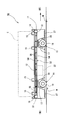
- the movable body 52 has two long members 54 that extend along the side surface of the vehicle body 11 and are arranged in parallel vertically on the side surface of the vehicle body 11. As shown in FIG. 9, a gap G is provided between the long member 54 and the side surface of the vehicle body 11, and front and rear ends of each long member 54 are connected to the detector 51, respectively. .
- the movable body 52 includes a plurality of locked members 55 that connect the upper and lower elongate members 54.
- the long member 54 is a rod-shaped member.
- the length of the long member 54 is slightly shorter than the length of the vehicle body 11.
- the elongated member 54 extends from the vicinity of the front end to the vicinity of the rear end on the side surface of the vehicle body 11.
- the locked member 55 is a substantially U-shaped member, the upper end of the locked member 55 is fixed to the upper long member 54, and the lower end of the locked member 55 is fixed to the lower long member 54. Has been.
- the locked member 55 protrudes outward from the long member 54 in the width direction of the vehicle body 11.
- the locked member 55 includes a locked portion where the locking tool 47 is easily locked, and the entire locked member 55 corresponds to the locked portion of the movable body 52.
- the plurality of locked members 55 are fixed to the long member 54 so as to maintain a constant distance from each other in the front-rear direction.
- the movable body 52 including two upper and lower long members 54 and a plurality of locked members 55 has a ladder-like structure. The movable body 52 can be displaced back and forth with respect to the vehicle body 11 by receiving a load in the front and rear direction on the locked member 55.
- the detector 51 is for detecting the displacement of the movable body 52 with respect to the vehicle body 11.
- the detector 51 includes a detection unit 56, a detection arm unit 57, a pair of coil springs 58 and a cover member 59.
- a proximal end portion of a detection arm portion 57 is connected to the detection portion 56.
- the detection arm portion 57 can tilt back and forth with the base end portion as a fulcrum.
- the distal end portion of the detection arm portion 57 is connected to the end portion of the long member 54.
- the detection arm portion 57 can tilt with respect to the long member 54.
- the detection unit 56 is a switch that switches from ON to OFF when the tilt of the detection arm unit 57 is detected.
- the pair of upper and lower long members 54 and the pair of front and rear detection arms 57 on the side surface of the vehicle body 11 constitute a parallel link mechanism that is displaced back and forth.
- the cover member 59 is a box-shaped member that covers the detection unit 56 and the detection arm unit 57.
- the cover member 59 is provided with an opening 60 through which the long member 54 is inserted.
- a pair of coil springs 58 that connect the cover member 59 and the detection arm portion 57 are provided.
- the axis of the coil spring 58 in the expansion / contraction direction coincides with the front-rear direction.
- the coil spring 58 is a biasing member that applies a tensile load in the front-rear direction to the detection arm portion 57.
- the urging force of the coil spring 58 urges the detection arm unit 57 to be kept at a neutral position where the displacement of the detection unit 56 is not detected.
- the detector 51 is connected in series with the exciting coil 42. In this embodiment, since four detectors 51 are provided, these detectors 51 are connected in series. In the present embodiment, when the movable body 52 is displaced forward or backward by using the locking tool 47, the two detectors 51 are simultaneously turned OFF, and the excitation of the excitation coils 42 and 46 is canceled. Therefore, since the electromagnetic switch 33 cuts off the power supply to the electric motor 20, the container-less automatic guided vehicle 50 comes to an emergency stop without using the controller 22.
- the automatic guided vehicle for containers 50 has the same effects as the effects (1), (3), and (4) of the first embodiment.
- the movable body 52 is disposed over the side surface of the vehicle body 11, and the long member 54 includes the plurality of locked members 55. For this reason, compared with 1st Embodiment, there are many places which can be latched in the movable body 52, and it is easy to latch the locking tool 47 on the movable body 52.
- the long member 54 and the pair of front and rear detection arms 57 on the side surface of the vehicle body 11 constitute a parallel link mechanism that is displaced forward and backward, when the movable body 52 is displaced forward or backward by the locking tool 47, The two detectors 51 are turned off simultaneously. Therefore, even if one of the detectors 51 fails and does not operate, the other detector 51 can reliably detect the displacement of the movable body 52, and the container automatic guided vehicle 50 can be surely brought to an emergency stop.
- the power circuit includes a self-holding circuit, but this is not a limitation.
- a latch may be provided in the detection arm portion of the detector so that the return to the neutral position is mechanically restricted after the detection arm portion is displaced to the switching position so that the detector does not turn on. In order to turn on the detector, the restriction by the latch may be released.
- the movable body tilting back and forth is used, but this is not restrictive.
- the movable body may have a structure that can slide back and forth. Further, in the case where a means for preventing malfunction during container loading is provided, a movable body that is displaced up and down may be used.
- the locking tool is not limited to a boat hook. If it is a locking tool that can be locked to the locked portion of the movable body, the structure is particularly free.
- the switch as a means for supplying / cutting off electric power to the electric motor in the power circuit is provided between the in-vehicle battery and the motor driver, but the position of the switch is not limited to this. For example, you may provide between the electric motor and motor driver as a drive part for driving
- the movable body 70 may be provided with a large number of shaft members 72 provided upright on one long member 71.
- the shaft member 72 corresponds to the locked portion.
- the shaft member 72 may be suspended downward.
- a shaft-like movable body 74 that extends upward from the detector 73 and can tilt forward, backward, left and right may be used.
- the movable body 74 is displaced by being tilted while being locked by the locking tool 47.
- the movable member may extend along the side surface of the vehicle body 11 and be a flexible string member 75 such as a wire rope or a synthetic fiber rope.
- the entire string-like member 75 corresponds to the locked portion.
- the traveling drive unit may have a configuration in which a hydraulic motor and an electrical element for driving the hydraulic motor are combined.
- the electrical elements include an electric motor that drives a hydraulic pump that supplies hydraulic oil to the hydraulic motor, and a hydraulic electromagnetic valve that serves as a brake means.
- the electric motor is driven by supplying electric power to the electric motor, and a hydraulic pump driven by the electric motor supplies hydraulic oil to the hydraulic motor.
- the hydraulic electromagnetic valve maintains a brake-released state in which hydraulic oil freely flows in the hydraulic piping by supplying electric power to the hydraulic electromagnetic valve as a brake means.
- the emergency stop device is operated to cut off the power supply to the electric motor that drives the hydraulic pump and cut off the power supply to the hydraulic electromagnetic valve.
- the supply of hydraulic fluid to the hydraulic motor is stopped by shutting off the power supply to the electric motor, and further, the hydraulic solenoid valve stops the flow of hydraulic oil to the hydraulic brake by cutting off the power supply to the hydraulic solenoid valve.
- the brake state is set to brake.
Landscapes
- Engineering & Computer Science (AREA)
- Aviation & Aerospace Engineering (AREA)
- Radar, Positioning & Navigation (AREA)
- Remote Sensing (AREA)
- Physics & Mathematics (AREA)
- General Physics & Mathematics (AREA)
- Automation & Control Theory (AREA)
- Mechanical Engineering (AREA)
- Control Of Position, Course, Altitude, Or Attitude Of Moving Bodies (AREA)
- Warehouses Or Storage Devices (AREA)
Abstract
本発明の目的は、無人搬送車から離れた位置にて無人搬送車に間接的に触れることにより非常停止を可能とする無人搬送車の提供にある。車体(11)と、車体(11)に備えられた走行用駆動部(20)と、車体(11)に搭載され、走行用駆動部(20)を制御する制御部(22)と、制御部(22)を介さずに走行中の非常停止を可能とする非常停止装置と、を備えたコンテナ用無人搬送車(10)において、非常停止装置は、車体(11)の側面に変位可能に設けられ、係止可能な被係止部を備えた可動体(32)と、可動体(32)の変位を検知する検知器(31)と、検知器(31)による可動体(32)の変位の検知に基づいて走行用駆動部(20)への電力供給を遮断する開閉器と、を備えた。
Description
この発明は、無人搬送車に関する。
近年では、港湾設備としてのコンテナターミナルにおいて、コンテナ運搬専用の無人搬送車によりコンテナを運搬することが提案されている。コンテナを搭載可能とする無人搬送車は、大型の無人搬送車(例えば、全長が15.0m、幅3.0m、高さ2.0m以上)である。この種の無人搬送車では、コンテナ搬送の効率向上のため、高速走行によるコンテナ搬送が求められていることから、最高速度は25km/h程度まで向上されている場合もある。
一方、無人搬送車の車体側部の前後には、非常停止手段としての非常停止ボタンがそれぞれ設けられている。これらの非常停止ボタンのいずれかが作業者により押されると、無人搬送車の駆動部を制御する制御部を介さずに駆動部の電源を直接遮断することが可能である。この種の非常停止手段は、関係法令およびJIS規格等により無人搬送車に対して要求されている条件である。
無人搬送車の非常停止に関係する従来技術としては、例えば、特許文献1に開示された潜り込み式無人搬送車の非常停止装置を挙げることができる。特許文献1では、ワゴンの下に潜り込ませて、その状態でワゴンを搬送する潜り込み式無人搬送車が開示されている。ワゴンの前端および後端には非常停止ボタンおよびバンパーが設けられている。例えば、非常停止ボタンが押されると、無人搬送車内に設けられた停止制御手段は無人搬送車を非常停止させる。
しかしながら、コンテナを運搬する無人搬送車は、特許文献1に開示された無人搬送車と比較すると著しく大型であり、無人搬送車の非常停止のために、作業者が走行中の車体に接近して非常停止ボタンに直接触れることは困難である。しかも、大型の無人搬送車が高速で走行するほど、非常停止ボタンに直接触れる困難性は高くなる。
本発明は上記の問題点に鑑みてなされたもので、本発明の目的は、無人搬送車から離れた位置にて無人搬送車に間接的に触れることにより非常停止を可能とする無人搬送車の提供にある。
上記の課題を解決するために、本発明は、車体と、前記車体に備えられた走行用駆動部と、前記車体に搭載され、前記走行用駆動部を制御する制御部と、前記制御部を介さずに走行中の非常停止を可能とする非常停止装置と、を備えた無人搬送車において、前記非常停止装置は、前記車体の側面に変位可能に設けられ、係止可能な被係止部を備えた可動体と、前記可動体の変位を検知する検知器と、前記検知器による前記可動体の変位の検知に基づいて前記走行用駆動部への電力供給を遮断する開閉器と、を備えたことを特徴とする。
本発明では、走行中の無人搬送車から離れた位置にて、作業者が被係止部に係止具を係止させて可動体を車体に対して変位させると、検知器が可動体の変位を検知する。検知器が可動体の変位を検知すると、開閉器は走行用駆動部への電力供給を遮断するため、無人搬送車は制御部を介さずに非常停止する。従って、無人搬送車を非常停止させる場合、係止具を用いて間接的に可動体を変位させることにより、無人搬送車に直接触れることなく無人搬送車から離れた位置にて無人搬送車を非常停止させることができる。
また、上記の無人搬送車において、前記可動体は、前記車体の側面に沿って延在するとともに、車体に対して変位可能な長尺部材と、前記長尺部材に固定され、前記被係止部を備えた被係止部材と、を有する構成としてもよい。
この場合、可動体が車体に対して変位する長尺部材を有するため、車体の側面にわたって前後方向に可動体が設けられる。よって、長尺部材の長手方向にわたって被係止部を備えた被係止部材を設けることが可能となり、特に複数の被係止部材を設ける場合、可動体に対する係止具の係止がより容易となる。
この場合、可動体が車体に対して変位する長尺部材を有するため、車体の側面にわたって前後方向に可動体が設けられる。よって、長尺部材の長手方向にわたって被係止部を備えた被係止部材を設けることが可能となり、特に複数の被係止部材を設ける場合、可動体に対する係止具の係止がより容易となる。
また、上記の無人搬送車において、前記可動体は前記車体の前後方向に変位可能である構成としてもよい。
可動体が前後方向へ変位可能であるため、荷の積み込み時に無人搬送車に上下方向の振動が生じても可動体は前後方向に変位することがない。このため、無人搬送車は、荷の積み込み時の振動を原因とする誤作動によって非常停止されることはない。
可動体が前後方向へ変位可能であるため、荷の積み込み時に無人搬送車に上下方向の振動が生じても可動体は前後方向に変位することがない。このため、無人搬送車は、荷の積み込み時の振動を原因とする誤作動によって非常停止されることはない。
また、上記の無人搬送車において、前記可動体は、前記車体の側面に沿って延在する可撓性の紐状部材である構成としてもよい。
この場合、車体の側面に延在する可撓性の紐状部材が車体に対して変位可能であって被係止部としての機能を備える。このため、係止具を紐状部材に係止させることにより、紐状部材を車体に対して変位させ、無人搬送車を非常停止させることができる。
この場合、車体の側面に延在する可撓性の紐状部材が車体に対して変位可能であって被係止部としての機能を備える。このため、係止具を紐状部材に係止させることにより、紐状部材を車体に対して変位させ、無人搬送車を非常停止させることができる。
本発明によれば、無人搬送車から離れた位置にて無人搬送車に間接的に触れることにより非常停止を可能とする無人搬送車を提供することができる。
(第1の実施形態)
以下、第1の実施形態に係る無人搬送車としてのコンテナ用無人搬送車について図面を参照して説明する。本実施形態のコンテナ用無人搬送車は、港湾設備としてのコンテナターミナルにおいて船舶とコンテナヤードとの間にてコンテナの荷役を受けてコンテナを搬送する。
以下、第1の実施形態に係る無人搬送車としてのコンテナ用無人搬送車について図面を参照して説明する。本実施形態のコンテナ用無人搬送車は、港湾設備としてのコンテナターミナルにおいて船舶とコンテナヤードとの間にてコンテナの荷役を受けてコンテナを搬送する。
図1に示すように、コンテナ用無人搬送車10の車体11は、荷としてのコンテナCを支持する荷台12を備えている。車体11の下部前側には左右一対の前輪13を備え、車体11の下部後側には左右一対の後輪14が備えられている。
荷台12は、40ft(フィート)の規格のコンテナ(以下「40ftコンテナ」と表記する)Cを支持可能である。また、20ft(フィート)の規格のコンテナ(図示せず、以下「20ftコンテナ」と表記する)の場合、荷台12は前後に2台の20ftコンテナを支持することが可能である。車体11の全長は40ftコンテナCの全長に合わせた長さとなっている。
車体11の幅方向の縁部付近には、荷台12に対する40ftコンテナCの幅方向の位置ずれを規制する複数のストッパ15が備えられている。また、車体11の前部および後部には、荷台12に搭載される40ftコンテナCの長さ方向の位置ずれを規制するストッパ16がそれぞれ設けられている。車体11の前部および後部にそれぞれ設けられるストッパ16は、20ftコンテナに対応可能である。
前輪13および後輪14について説明すると、車体11に対して水平方向に旋回自在の旋回支持部17が設けられている。図2、図3に示すように、旋回支持部17の下端には、車軸(図示せず)およびデフ機構(図示せず)を収容する軸ケース18が連結されている。車軸の両端にはタイヤ19がそれぞれ取り付けられており、前輪13および後輪14は、2本のタイヤ19を備えるダブルタイヤ構造となっている。軸ケース18には走行用の電動モータ20が設けられている。電動モータ20は走行用駆動部に相当する。2本のタイヤ19の間において電動モータ20の長手方向がほぼ水平となるように、電動モータ20は軸ケース18に対して固定されている。電動モータ20の回転力はデフ機構を介して車軸に伝達される。従って、全ての車輪(前輪13および後輪14)には、走行のための駆動力が対応する電動モータ20からそれぞれ伝達される。本実施形態では電動モータ20としてサーボモータが用いられている。
図3に示すように、各旋回支持部17の上部には、操舵機構21がそれぞれ連結されている。操舵機構21は、図示されないが旋回支持部17を旋回させるための操舵用の電動モータおよび減速機を備えている。従って、前輪13および後輪14は操舵機構21の作動により互いに独立して操舵可能である。本実施形態では、前輪13および後輪14の最大操舵角度は、直進走行時の操舵角度を0度としたとき、右方向に90度以上、左方向に90度以上に設定されている。従って、前輪13および後輪14の操舵可能な操舵角度は、右方向に0~90度以上であって左方向に0~90度以上である。つまり、前輪13および後輪14の操舵可能な操舵角度は、直進走行時の操舵角度0度に対して左右方向にそれぞれ90度以上に設定されている。
車体11には、コンテナ用無人搬送車10の各部を制御するコントローラ22が搭載されている。図4に示すように、コントローラ22は、演算処理部23と、記憶部24および通信部25を備えている。演算処理部23は各種のプログラムを実行や各種のデータ処理を行う。記憶部24は各種のプログラムを実行や各種のデータを記憶する。通信部25は、地上側に設置された上位のコンピュータ(図示せず)との通信を行う。本実施形態では、コンテナ用無人搬送車10は、上位のコンピュータからの指令に基づいてコンテナターミナルにおいて走行したり所定の位置に停止したりする。上位のコンピュータはコンテナターミナルにおけるコンテナ用無人搬送車10の運行状況を把握するほか、コンテナターミナルの荷役状況を把握する。
本実施形態では、コントローラ22は各電動モータ20の駆動を制御するモータドライバ26と接続されており、モータドライバ26に指令する機能を有する。モータドライバ26は、コントローラ22の指令に応じた電力を電動モータ20へ供給する。従って、コントローラ22は、モータドライバ26へ指令することにより、電動モータ20の駆動制御により車速制御を行うことができる。コントローラ22は、例えば、高速走行(25km/h)のためのモータドライバ26への指令と、低速走行(0.5km/h)するための指令のほか、加速又は減速の指令をモータドライバ26に対して伝達することできる。コントローラ22は制御部に相当する。
また、本実施形態では、コントローラ22は各操舵機構21と接続されており、各操舵機構21はコントローラ22の指令に基づいて対応する車輪を操舵する。各車輪は対応する操舵機構21により互いに独立して操舵される。コントローラ22は、直進走行する場合には、前輪13および後輪14の操舵角度が0度となるように各操舵機構21を制御する。また、コントローラ22は、カーブとなっている経路を通過する場合には、前輪13および後輪14のカーブの経路に対応するために必要な操舵角度となるように各操舵機構21を制御する。また、本実施形態では、車体11の向きを変更せずに斜めに走行したり、車体11の向きを変更せず車体11の幅方向へ走行したりするように各操舵機構21が制御される。
図1、図2に示すように、車体11の底部における前部および後部には、路面に埋設されたマーカーMを読み取る位置検出センサ27が備えられている。位置検出センサ27はマーカーMを読み取ることにより位置検出を行う。本実施形態のマーカーMは磁気マーカーであり、これらのマーカーMにはマーカー毎のID情報(X、Y座標の位置情報)が保持されている。複数のマーカーMが路面に埋設されることで、例えば、コンテナターミナルにおいてコンテナ用無人搬送車10の走行経路が形成される。位置検出センサ27はコントローラ22と接続されている。コントローラ22は、位置検出センサ27の検出信号に基づいてコンテナ用無人搬送車10の位置を認識する。
ところで、本実施形態のコンテナ用無人搬送車10は、走行中のコンテナ用無人搬送車10を非常停止させるための非常停止装置を備えている。非常停止装置は、車体11の左右の側面における前端付近および後端付近に設けた検知器31と、検知器31に連結され、変位可能に設けられた可動体32と、検知器31による可動体32の検知により電動モータ20への電力供給を遮断する電磁開閉器33と、を備えている。非常停止装置の作動により、コントローラ22を介さずにコンテナ用無人搬送車10が非常停止される。
検知器31は、車体11に対する可動体32の変位を検知するためのものである。図5に示すように、検知器31は、検知部35、検知アーム部36およびカバー部材37を備えている。検知部35には、検知アーム部36の基端部が接続されている。検知アーム部36は、基端部を支点として前後に傾動可能である。検知アーム部36の先端部は可動体32の端部と連結されている。検知部35は検知アーム部36の傾動を検知するとONからOFFに切り替わるスイッチである。検知器31には、検知アーム部36が検知部35をONからOFFに切り替える位置(切替位置)まで傾動されても、検知アーム部36をONの位置(中立位置)へ復帰させるための付勢手段(図示せず)が設けられている。付勢手段はコイルばねが用いられている。カバー部材37は検知部35の外周を覆う部材である。
可動体32は、検知アーム部36に接続される取付部38と、取付部38に一体形成された略U字状の被係止部39とを有している。取付部38は長手方向が上下となるように検知アーム部36の先端部に固定されている。被係止部39の一対の端部が上下となるように、取付部38に固定されている。従って、図3に示すように、可動体32は、車体11の幅方向において外側へ向けて張り出している。被係止部39は可動体32において後述する係止具47が係止され易い部位である。可動体32は、前後方向の荷重を受けることにより、検知アーム部36と一体となって前後に傾動して変位可能である。可動体32は、車体11に設けた各検知器31にそれぞれ連結されている。
次に、開閉器としての電磁開閉器33について説明する。図6に示すように、電磁開閉器33は、開閉可能な接点41と接点41を開閉するための励磁コイル42とを備えたコンタクタである。本実施形態の電磁開閉器33は電力回路において車載バッテリ43とモータドライバ26との間に設けられている。電磁開閉器33は、励磁コイル42が通電により励磁されると接点41を閉じて車載バッテリ43から電動モータ20へ通電する。励磁コイル42の励磁が解消されると、電磁開閉器33は、接点41を開いて車載バッテリ43から電動モータ20への通電を遮断する。電力回路において検知器31は、励磁コイル42と直列に接続されている。本実施形態では4個の検知器31を備えているため、これらの検知器31は直列に接続されている。
図6に示す電力回路には、励磁コイル42と検知器31との間に並列接続されたスイッチ44、45を備えている。スイッチ44を開閉するための励磁コイル46が検知器31と直列接続されている。励磁コイル46の励磁によりスイッチ44は閉じる。従って、スイッチ44および励磁コイル46はリレーを構成する。スイッチ44は励磁コイル46の励磁が解除されない限り閉じた状態を維持するが、一度、励磁コイル46の励磁が解除されると、開いた状態を維持する。つまり、一度、検知器31の検知部35がOFFとなると、検知部35がONになっても、スイッチ44は閉じることはない。つまり、スイッチ44および励磁コイル46は自己保持回路を構成している。
スイッチ45は、常開のスイッチであり、コンテナ用無人搬送車10を非常停止の状態から走行可能な状態に復帰させるための復帰用のスイッチである。励磁コイル46の励磁が解除されている状態では、スイッチ44が開いているが、スイッチ45を操作して閉じることにより、励磁コイル46は励磁され、スイッチ44は閉じて通電状態となる。また、通電により励磁コイル42も励磁されるため、接点41は閉じて電磁開閉器33は通電状態となり、コンテナ用無人搬送車10は走行可能な状態に復帰される。スイッチ45は、車体11に設けられ、作業者が直接操作可能なボタンである。
次に、図7に示す係止具47について説明する。係止具47は、小型船舶を引き寄せるために用いられるボートフックであり、コンテナターミナルにおいて常備されている。本実施形態では、コンテナ用無人搬送車10を非常停止させるための係止具47として用いられる。係止具47は、伸縮式のポール部48とポール部48の先端部に取り付けられたフック部49を備えている。係止具47は、ポール部48を伸長した場合は、2m以上の長さとなる。フック部49は、可動体32の被係止部39に係止可能な鉤状に形成されている。係止具47におけるフック部49を設けた先端部と反対側となる端部は、作業者が把持する部位である。
次に、コンテナ用無人搬送車10の非常停止について説明する。コンテナ用無人搬送車10は、走行経路におけるマーカーMを読み取りつつ、現在位置を確認しながら走行経路走行する。コンテナ用無人搬送車10が走行しているとき、励磁コイル42が励磁されており、電磁開閉器33は通電状態にある。このとき、励磁コイル46は励磁されてスイッチ44は閉じて通電されている。このため、車載バッテリ43の電力は電磁開閉器33およびモータドライバ26を介して電動モータ20へ供給される。
通常に走行しているコンテナ用無人搬送車10を、何らかの理由により非常停止させる場合、作業者は伸長させた係止具47のフック部49を、可動体32の被係止部39に係止させ、可動体32を傾動させ、車体11に対して変位させる。係止具47を用いて検知アーム部36をONの位置(中立位置)からOFFに切り替わる位置(切替位置)まで傾動させると、作業者は係止具47を手離してコンテナ用無人搬送車10から離れるようにすればよい。
検知アーム部36が切替位置まで傾動されると、検知部35はOFFとなり、励磁コイル42、46の励磁が解消される。励磁コイル42の励磁が解消されることにより、電磁開閉器33の接点41が開いて通電が遮断され、電動モータ20は停止する。電動モータ20の停止により、コンテナ用無人搬送車10は非常停止する。励磁コイル46の励磁が解消されることによりスイッチ44が開く。このため、検知アーム部36を中立位置へ復帰させるための付勢手段の付勢により、検知アーム部36が切替位置から中立位置へ復帰しても、励磁コイル42、46が励磁されることはなく検知部35はONとならない。このように、係止具47を用いて非常停止装置を作動させることにより、コントローラ22を介さずに電動モータ20への通電を直接遮断し、コンテナ用無人搬送車10は非常停止される。
コンテナ用無人搬送車10を非常停止の状態から通常の走行が可能な状態に切り替えるためには、作業者の操作によりスイッチ45を閉じればよい。スイッチ45を閉じることにより、励磁コイル42、46が励磁され、電磁開閉器33の接点41が閉じられるとともに、スイッチ44が閉じられる。スイッチ44が閉じることにより、スイッチ45が開いても、励磁コイル42、46の励磁を継続することが可能である。このため、車載バッテリ43の電力は電磁開閉器33およびモータドライバ26を介して電動モータ20へ供給可能である。
本実施形態に係るコンテナ用無人搬送車10は、以下の作用効果を奏する。
(1)走行中のコンテナ用無人搬送車10から離れた位置にて、作業者が被係止部39に係止具47を係止させて可動体32を車体11に対して変位させると、検知器31が可動体32の変位を検知する。検知器31が可動体32の変位を検知すると、電磁開閉器33は電動モータ20への電力供給を遮断するため、コンテナ用無人搬送車10はコントローラ22を介さずに非常停止する。従って、コンテナ用無人搬送車10を非常停止させる場合、係止具47を用いて間接的に可動体32を変位させることにより、コンテナ用無人搬送車10から離れた位置にてコンテナ用無人搬送車10を非常停止させることができる。大型のコンテナ用無人搬送車10が高速走行中であっても、コンテナ用無人搬送車10の非常停止は容易に行うことができる。
(1)走行中のコンテナ用無人搬送車10から離れた位置にて、作業者が被係止部39に係止具47を係止させて可動体32を車体11に対して変位させると、検知器31が可動体32の変位を検知する。検知器31が可動体32の変位を検知すると、電磁開閉器33は電動モータ20への電力供給を遮断するため、コンテナ用無人搬送車10はコントローラ22を介さずに非常停止する。従って、コンテナ用無人搬送車10を非常停止させる場合、係止具47を用いて間接的に可動体32を変位させることにより、コンテナ用無人搬送車10から離れた位置にてコンテナ用無人搬送車10を非常停止させることができる。大型のコンテナ用無人搬送車10が高速走行中であっても、コンテナ用無人搬送車10の非常停止は容易に行うことができる。
(2)可動体32を車体11の側面における前後端付近に検知器31を配置したことから、係止具47は可動体32に係止され易い。可動体32が前後方向へ変位可能であるため、コンテナ積み込み時にコンテナ用無人搬送車10に上下方向の振動が生じても可動体32は前後に変位せず、コンテナ用無人搬送車10がコンテナ積み込み時の振動を原因とする誤作動によって非常停止されることはない。
(3)自己保持回路が電力回路に含まれているため、切替位置へ変位した検知アーム部36が中立位置へ復帰しても、電磁開閉器33は通電を遮断し、電力が電動モータ20へ供給されず、非常停止の状態を保つことができる。検知アーム部36を中立位置へ復帰させるための付勢手段が設けられているため、検知アーム部36が切替位置まで傾動されても、検知アーム部36を中立位置へ復帰させることができる。
(4)複数(4個)の検知器31が直列に接続されており、これらの検知器31のうちいずれかの検知器31がOFFとなることにより、コンテナ用無人搬送車10は確実に非常停止される。
(第2の実施形態)
次に、第2の実施形態に係る無人搬送車について説明する。本実施形態では、可動体の構成が第1の実施形態と異なる。第1の実施形態と共通する構成については、第1の実施形態の説明を援用し、同じ符号を用いる。
次に、第2の実施形態に係る無人搬送車について説明する。本実施形態では、可動体の構成が第1の実施形態と異なる。第1の実施形態と共通する構成については、第1の実施形態の説明を援用し、同じ符号を用いる。
本実施形態のコンテナ用無人搬送車50の非常停止装置は、車体11の左右の側面における前端付近および後端付近に設けた検知器51と、検知器51に連結され、変位可能に設けられた可動体52と、電磁開閉器33と、を備えている。
図8に示すように、可動体52は、車体11の側面において、車体11の側面に沿って延在するとともに、上下に平行に配置された2本の長尺部材54を有している。図9に示すように、長尺部材54と車体11の側面との間は、間隔Gが設けられており、各長尺部材54の前後の端部は、検知器51にそれぞれ連結されている。
可動体52は、上下の長尺部材54を連結する複数の被係止部材55を備えている。長尺部材54は棒状の部材である。長尺部材54の長さは車体11の長さより僅かに短い。長尺部材54は、車体11の側面において前端付近から後端付近まで延在する。
被係止部材55は略U字状の部材であり、被係止部材55の上端は上側の長尺部材54に固定され、被係止部材55の下端は下側の長尺部材54に固定されている。被係止部材55は、車体11の幅方向において長尺部材54よりも外側へ突出している。被係止部材55は、係止具47が係止され易い被係止部を備えており、被係止部材55の全体が可動体52の被係止部に相当する。複数の被係止部材55は、前後方向において互いに一定の間隔を保つように長尺部材54に固定されている。上下の2本の長尺部材54と複数の被係止部材55を備える可動体52は梯子状の構造となっている。可動体52は被係止部材55に前後方向の荷重を受けることにより、車体11に対して前後に変位可能である。
検知器51は、車体11に対する可動体52の変位を検知するためのものである。図10に示すように、検知器51は、検知部56、検知アーム部57、一対のコイルばね58およびカバー部材59を備えている。検知部56には、検知アーム部57の基端部が接続されている。検知アーム部57は、基端部を支点として前後に傾動可能である。検知アーム部57の先端部は長尺部材54の端部と連結されている。検知アーム部57は長尺部材54に対して傾動可能である。検知部56は検知アーム部57の傾動を検知するとONからOFFに切り替わるスイッチである。車体11の側面における上下一対の長尺部材54および前後一対の検知アーム部57は前後に変位する平行リンク機構を構成する。
カバー部材59は、検知部56および検知アーム部57を覆う箱状の部材である。カバー部材59には、長尺部材54が挿通される開口部60が設けられている。カバー部材59と検知アーム部57とを接続する一対のコイルばね58が設けられている。コイルばね58の伸縮方向の軸線は前後方向と一致している。コイルばね58は、検知アーム部57に対して前後方向の引っ張り荷重を付与する付勢部材である。コイルばね58の付勢力は、検知部56の変位が検知されない中立位置に検知アーム部57を保つように付勢する。
図11に示す電力回路では、検知器51は、励磁コイル42と直列に接続されている。本実施形態では4個の検知器51を備えているため、これらの検知器51は直列に接続されている。本実施形態では、係止具47を用いることにより可動体52が前方又は後方へ変位されると、2個の検知器51が同時にOFFとなり、励磁コイル42、46の励磁が解消される。よって、電磁開閉器33は電動モータ20への電力供給を遮断するため、コンテナ用無人搬送車50はコントローラ22を介さずに非常停止する。
本実施形態のコンテナ用無人搬送車50は、第1の実施形態の作用効果(1)、(3)、(4)と同等の作用効果を奏する。また、本実施形態によれば、車体11の側面にわたって可動体52が配置され、長尺部材54は複数の被係止部材55を備えている。このため、第1の実施形態と比較して、可動体52において係止可能な箇所が多く、可動体52に係止具47を係止させ易い。また、車体11の側面における長尺部材54および前後一対の検知アーム部57は前後に変位する平行リンク機構を構成するため、係止具47によって可動体52が前方又は後方へ変位されると、2個の検知器51が同時にOFFとなる。よって、一方の検知器51が故障して作動しなくても他方の検知器51が可動体52の変位を確実に検知でき、コンテナ用無人搬送車50を確実に非常停止させることができる。
本発明は、上記の実施形態に限定されるものではなく発明の趣旨の範囲内で種々の変更が可能であり、例えば、次のように変更してもよい。
○ 上記の実施形態では、電力回路に自己保持回路を含む構成としたがこの限りではない。例えば、検知器の検知アーム部にラッチを設けて、検知アーム部が切替位置に変位した後に中立位置への復帰を機械的に規制し、検知器がONとならないようにしてもよい。検知器をONにするためには、ラッチによる規制を解除すればよい。
○ 上記の実施形態では、前後に傾動する可動体を用いたがこの限りではない。可動体は前後にスライド可能な構造であってもよい。また、コンテナ積込み時の誤作動を防止する手段を備えている場合では、上下に変位する可動体であってもよい。
○ 上記の実施形態では、係止具としてボートフックを用いる例について説明したが、係止具はボートフックに限定されない。可動体の被係止部に係止可能な係止具であれば特に構造については自由である。
○ 上記の実施形態では、電力回路において電動モータへの電力を供給・遮断する手段としての開閉器を車載バッテリとモータドライバとの間に設けたが、開閉器の位置はこの限りではない。例えば、電力回路において走行用駆動部としての電動モータとモータドライバの間に設けてもよい。この場合、三相の配線を遮断可能な開閉器が用いられる。
○ 上記の実施形態では、被係止部を有する可動体としての略U字状の可動体、あるいは長尺部材および略U字状の被係止部材を備えた可動体としたが、可動体はこれらに制限されない。例えば、図12(a)に示す別例1のように、一本の長尺部材71に立設された多数の軸部材72が設けられた可動体70としてもよい。この場合、軸部材72が被係止部に相当する。なお、軸部材72は下方へ垂設されてもよい。また、図12(b)に示す別例2のように、検知器73から上方へ延在し、かつ、前後左右に傾動可能な軸状の可動体74としてもよい。この場合、可動体74は係止具47により係止されて傾動することにより変位する。図12(c)に示す別例3のように、可動部材を、車体11の側面に沿って延在し、ワイヤーロープや化繊ロープ等の可撓性の紐状部材75としてもよい。この場合、紐状部材75を受承するフック76を車体11の側面に設けることが好ましい。紐状部材75では紐状部材75の全体が被係止部に相当する。
○ 上記の実施形態では、走行用駆動部として電動モータの例について説明したが、走行用駆動部は電動モータに限定されない。走行用駆動部は、例えば、油圧モータと油圧モータの駆動するための電気的要素とを組み合わせた構成であってもよい。電気的要素としては、例えば、油圧モータへ作動油を供給する油圧ポンプを駆動する電動モータおよびブレーキ手段としての油圧電磁バルブである。この場合、走行時には電動モータへの電力供給により電動モータが駆動され、電動モータによって駆動される油圧ポンプが作動油を油圧モータへ供給する。作動油の供給を受けて油圧モータが駆動され、無人搬送車が走行する。走行時においては、ブレーキ手段としての油圧電磁バルブに対する電力供給により、油圧電磁バルブは、油圧配管における作動油が自由に流れるブレーキ解除の状態を保つ。一方、無人搬送車を非常停止させる場合には、非常停止装置を作動させ、油圧ポンプを駆動する電動モータへの電力供給を遮断し、油圧電磁バルブへの電力供給を遮断する。電動モータへの電力供給の遮断により、油圧モータへの作動油の供給が停止され、さらに、油圧電磁バルブへの電力供給の遮断により、油圧電磁バルブは作動油の流れを止めて油圧ブレーキに対して制動するブレーキ状態となる。その結果、無人搬送車は非常停止する。なお、油圧に代えて空気圧を利用した空気圧モータを有する走行用駆動部としてもよい。
○ 上記の実施形態では、前後に傾動する可動体を用いたがこの限りではない。可動体は前後にスライド可能な構造であってもよい。また、コンテナ積込み時の誤作動を防止する手段を備えている場合では、上下に変位する可動体であってもよい。
○ 上記の実施形態では、係止具としてボートフックを用いる例について説明したが、係止具はボートフックに限定されない。可動体の被係止部に係止可能な係止具であれば特に構造については自由である。
○ 上記の実施形態では、電力回路において電動モータへの電力を供給・遮断する手段としての開閉器を車載バッテリとモータドライバとの間に設けたが、開閉器の位置はこの限りではない。例えば、電力回路において走行用駆動部としての電動モータとモータドライバの間に設けてもよい。この場合、三相の配線を遮断可能な開閉器が用いられる。
○ 上記の実施形態では、被係止部を有する可動体としての略U字状の可動体、あるいは長尺部材および略U字状の被係止部材を備えた可動体としたが、可動体はこれらに制限されない。例えば、図12(a)に示す別例1のように、一本の長尺部材71に立設された多数の軸部材72が設けられた可動体70としてもよい。この場合、軸部材72が被係止部に相当する。なお、軸部材72は下方へ垂設されてもよい。また、図12(b)に示す別例2のように、検知器73から上方へ延在し、かつ、前後左右に傾動可能な軸状の可動体74としてもよい。この場合、可動体74は係止具47により係止されて傾動することにより変位する。図12(c)に示す別例3のように、可動部材を、車体11の側面に沿って延在し、ワイヤーロープや化繊ロープ等の可撓性の紐状部材75としてもよい。この場合、紐状部材75を受承するフック76を車体11の側面に設けることが好ましい。紐状部材75では紐状部材75の全体が被係止部に相当する。
○ 上記の実施形態では、走行用駆動部として電動モータの例について説明したが、走行用駆動部は電動モータに限定されない。走行用駆動部は、例えば、油圧モータと油圧モータの駆動するための電気的要素とを組み合わせた構成であってもよい。電気的要素としては、例えば、油圧モータへ作動油を供給する油圧ポンプを駆動する電動モータおよびブレーキ手段としての油圧電磁バルブである。この場合、走行時には電動モータへの電力供給により電動モータが駆動され、電動モータによって駆動される油圧ポンプが作動油を油圧モータへ供給する。作動油の供給を受けて油圧モータが駆動され、無人搬送車が走行する。走行時においては、ブレーキ手段としての油圧電磁バルブに対する電力供給により、油圧電磁バルブは、油圧配管における作動油が自由に流れるブレーキ解除の状態を保つ。一方、無人搬送車を非常停止させる場合には、非常停止装置を作動させ、油圧ポンプを駆動する電動モータへの電力供給を遮断し、油圧電磁バルブへの電力供給を遮断する。電動モータへの電力供給の遮断により、油圧モータへの作動油の供給が停止され、さらに、油圧電磁バルブへの電力供給の遮断により、油圧電磁バルブは作動油の流れを止めて油圧ブレーキに対して制動するブレーキ状態となる。その結果、無人搬送車は非常停止する。なお、油圧に代えて空気圧を利用した空気圧モータを有する走行用駆動部としてもよい。
10 コンテナ用無人搬送車
11 車体
20 電動モータ(走行用駆動部としての)
22 コントローラ(制御部としての)
31、51、73 検知器
32、52、70、74 可動体
33 電磁開閉器(開閉器としての)
35、56 検知部
36、57 検知アーム部
39 被係止部
41 接点(電磁開閉器)
42 励磁コイル(電磁開閉器)
44 スイッチ(リレー)
45 スイッチ(復帰用)
46 励磁コイル
47 係止具
54、71 長尺部材
55 被係止部材
58 コイルばね
60 開口部
72 軸部材
75 紐状部材
C 40ftコンテナ
G 間隙
11 車体
20 電動モータ(走行用駆動部としての)
22 コントローラ(制御部としての)
31、51、73 検知器
32、52、70、74 可動体
33 電磁開閉器(開閉器としての)
35、56 検知部
36、57 検知アーム部
39 被係止部
41 接点(電磁開閉器)
42 励磁コイル(電磁開閉器)
44 スイッチ(リレー)
45 スイッチ(復帰用)
46 励磁コイル
47 係止具
54、71 長尺部材
55 被係止部材
58 コイルばね
60 開口部
72 軸部材
75 紐状部材
C 40ftコンテナ
G 間隙
Claims (4)
- 車体と、
前記車体に備えられた走行用駆動部と、
前記車体に搭載され、前記走行用駆動部を制御する制御部と、
前記制御部を介さずに走行中の非常停止を可能とする非常停止装置と、を備えた無人搬送車において、
前記非常停止装置は、
前記車体の側面に変位可能に設けられ、係止可能な被係止部を備えた可動体と、
前記可動体の変位を検知する検知器と、
前記検知器による前記可動体の変位の検知に基づいて前記走行用駆動部への電力供給を遮断する開閉器と、を備えたことを特徴とする無人搬送車。 - 前記可動体は、
前記車体の側面に沿って延在するとともに、車体に対して変位可能な長尺部材と、
前記長尺部材に固定され、前記被係止部を備えた被係止部材と、を有することを特徴とする請求項1記載の無人搬送車。 - 前記可動体は前記車体の前後方向に変位可能であることを特徴とする請求項1又は2記載の無人搬送車。
- 前記可動体は、前記車体の側面に沿って延在する可撓性の紐状部材であることを特徴とする請求項1記載の無人搬送車。
Applications Claiming Priority (2)
| Application Number | Priority Date | Filing Date | Title |
|---|---|---|---|
| JP2017-008278 | 2017-01-20 | ||
| JP2017008278A JP6766657B2 (ja) | 2017-01-20 | 2017-01-20 | コンテナ用無人搬送車 |
Publications (1)
| Publication Number | Publication Date |
|---|---|
| WO2018135260A1 true WO2018135260A1 (ja) | 2018-07-26 |
Family
ID=62908956
Family Applications (1)
| Application Number | Title | Priority Date | Filing Date |
|---|---|---|---|
| PCT/JP2017/046727 Ceased WO2018135260A1 (ja) | 2017-01-20 | 2017-12-26 | 無人搬送車 |
Country Status (2)
| Country | Link |
|---|---|
| JP (1) | JP6766657B2 (ja) |
| WO (1) | WO2018135260A1 (ja) |
Cited By (1)
| Publication number | Priority date | Publication date | Assignee | Title |
|---|---|---|---|---|
| CN111605957A (zh) * | 2020-05-26 | 2020-09-01 | 隆链智能科技(上海)有限公司 | 一种仓储货物运输系统及其运行方法 |
Families Citing this family (1)
| Publication number | Priority date | Publication date | Assignee | Title |
|---|---|---|---|---|
| CN110428209B (zh) | 2019-08-16 | 2020-10-27 | 灵动科技(北京)有限公司 | 一种盘点设备、盘点管理系统及盘点方法 |
Citations (2)
| Publication number | Priority date | Publication date | Assignee | Title |
|---|---|---|---|---|
| JPH02256540A (ja) * | 1989-03-30 | 1990-10-17 | Nissan Motor Co Ltd | 無人搬送車の障害物検出装置 |
| JPH0552905U (ja) * | 1991-12-03 | 1993-07-13 | 村田機械株式会社 | 無人走行車 |
Family Cites Families (4)
| Publication number | Priority date | Publication date | Assignee | Title |
|---|---|---|---|---|
| JPS5781976A (en) * | 1980-11-07 | 1982-05-22 | Hitachi Ltd | Safety device for moving large sized device |
| JPS611554A (ja) * | 1984-06-14 | 1986-01-07 | Mitsubishi Electric Corp | 移動台車装置 |
| JP2001228919A (ja) * | 2000-02-18 | 2001-08-24 | Yaskawa Electric Corp | 接触型障害物検出装置とそれを備えた無人走行車 |
| JP4270078B2 (ja) * | 2004-09-03 | 2009-05-27 | トヨタ車体株式会社 | 無人搬送車の制御装置 |
-
2017
- 2017-01-20 JP JP2017008278A patent/JP6766657B2/ja active Active
- 2017-12-26 WO PCT/JP2017/046727 patent/WO2018135260A1/ja not_active Ceased
Patent Citations (2)
| Publication number | Priority date | Publication date | Assignee | Title |
|---|---|---|---|---|
| JPH02256540A (ja) * | 1989-03-30 | 1990-10-17 | Nissan Motor Co Ltd | 無人搬送車の障害物検出装置 |
| JPH0552905U (ja) * | 1991-12-03 | 1993-07-13 | 村田機械株式会社 | 無人走行車 |
Cited By (2)
| Publication number | Priority date | Publication date | Assignee | Title |
|---|---|---|---|---|
| CN111605957A (zh) * | 2020-05-26 | 2020-09-01 | 隆链智能科技(上海)有限公司 | 一种仓储货物运输系统及其运行方法 |
| CN111605957B (zh) * | 2020-05-26 | 2021-01-19 | 隆链智能科技(上海)有限公司 | 一种仓储货物运输系统及其运行方法 |
Also Published As
| Publication number | Publication date |
|---|---|
| JP6766657B2 (ja) | 2020-10-14 |
| JP2018115068A (ja) | 2018-07-26 |
Similar Documents
| Publication | Publication Date | Title |
|---|---|---|
| US20210179403A1 (en) | Omnidirectional Cart Transport Mechanism | |
| ES2948528T3 (es) | Sistema de control con varios modos de funcionamiento de una carretilla elevadora con horquillas | |
| JP5847189B2 (ja) | Isoコンテナ用大型輸送車両 | |
| JPH10120393A (ja) | フロアー運搬機 | |
| CN104914860A (zh) | 叉车型无人运输车、其控制方法以及控制装置 | |
| JP6766698B2 (ja) | コンテナ用無人搬送車 | |
| CN112140884A (zh) | 自动驾驶车辆的操作装置 | |
| JP2009025984A (ja) | 搬送車の走行制御装置 | |
| CN108622102A (zh) | 车辆输入操作辅助装置 | |
| JP6766657B2 (ja) | コンテナ用無人搬送車 | |
| CN204178235U (zh) | 一种新型叉车型agv小车 | |
| US11850945B2 (en) | Power supply device for electric work vehicle | |
| JP7215345B2 (ja) | 無人搬送車 | |
| JP2003267691A (ja) | フォークリフト | |
| JP5502317B2 (ja) | 軌道走行車両の走行制御装置 | |
| JP2003131738A (ja) | 搬送台車の非常停止方法および非常停止システム | |
| JP7365619B2 (ja) | 台車および乗り物 | |
| JP4359209B2 (ja) | 杭打機 | |
| US20260125084A1 (en) | Transport Facility | |
| JP7700692B2 (ja) | 自動走行車 | |
| JP5817654B2 (ja) | フォークリフト | |
| JP2021049829A (ja) | 作業車 | |
| JP4391500B2 (ja) | 逸脱防止装置付自動運転車両 | |
| JP7207667B2 (ja) | パレットの載置部構造 | |
| CN114348916A (zh) | 用于检测关于可至少部分自动化运行的工业卡车中的货物载体的扩展的信息的方法 |
Legal Events
| Date | Code | Title | Description |
|---|---|---|---|
| 121 | Ep: the epo has been informed by wipo that ep was designated in this application |
Ref document number: 17892809 Country of ref document: EP Kind code of ref document: A1 |
|
| NENP | Non-entry into the national phase |
Ref country code: DE |
|
| 122 | Ep: pct application non-entry in european phase |
Ref document number: 17892809 Country of ref document: EP Kind code of ref document: A1 |