WO2018131425A1 - 分割環表面側部材、分割環支持側部材、分割環、静止側部材ユニット及び方法 - Google Patents
分割環表面側部材、分割環支持側部材、分割環、静止側部材ユニット及び方法 Download PDFInfo
- Publication number
- WO2018131425A1 WO2018131425A1 PCT/JP2017/046068 JP2017046068W WO2018131425A1 WO 2018131425 A1 WO2018131425 A1 WO 2018131425A1 JP 2017046068 W JP2017046068 W JP 2017046068W WO 2018131425 A1 WO2018131425 A1 WO 2018131425A1
- Authority
- WO
- WIPO (PCT)
- Prior art keywords
- split ring
- side member
- gas turbine
- surface side
- combustion gas
- Prior art date
Links
- 239000007789 gas Substances 0.000 claims abstract description 181
- 239000000567 combustion gas Substances 0.000 claims abstract description 108
- 238000001816 cooling Methods 0.000 claims description 179
- 230000007246 mechanism Effects 0.000 claims description 111
- 239000000463 material Substances 0.000 claims description 40
- 238000005192 partition Methods 0.000 claims description 40
- 229910052751 metal Inorganic materials 0.000 claims description 31
- 239000002184 metal Substances 0.000 claims description 31
- 238000011144 upstream manufacturing Methods 0.000 claims description 26
- 239000011153 ceramic matrix composite Substances 0.000 claims description 16
- 238000004519 manufacturing process Methods 0.000 claims description 12
- 230000011218 segmentation Effects 0.000 claims description 5
- 230000003746 surface roughness Effects 0.000 claims description 3
- 239000002131 composite material Substances 0.000 abstract description 4
- 239000000919 ceramic Substances 0.000 abstract description 3
- 238000007789 sealing Methods 0.000 description 19
- HBMJWWWQQXIZIP-UHFFFAOYSA-N silicon carbide Chemical compound [Si+]#[C-] HBMJWWWQQXIZIP-UHFFFAOYSA-N 0.000 description 5
- 229910010271 silicon carbide Inorganic materials 0.000 description 5
- 238000006243 chemical reaction Methods 0.000 description 4
- 230000009257 reactivity Effects 0.000 description 4
- 239000000835 fiber Substances 0.000 description 3
- 239000000446 fuel Substances 0.000 description 3
- 230000002093 peripheral effect Effects 0.000 description 3
- 238000013459 approach Methods 0.000 description 2
- 238000005452 bending Methods 0.000 description 2
- 238000002485 combustion reaction Methods 0.000 description 2
- 238000009434 installation Methods 0.000 description 2
- 238000000638 solvent extraction Methods 0.000 description 2
- 229910018072 Al 2 O 3 Inorganic materials 0.000 description 1
- 229910000990 Ni alloy Inorganic materials 0.000 description 1
- 238000005266 casting Methods 0.000 description 1
- 239000000470 constituent Substances 0.000 description 1
- 238000005520 cutting process Methods 0.000 description 1
- 230000007423 decrease Effects 0.000 description 1
- 238000010586 diagram Methods 0.000 description 1
- 230000000694 effects Effects 0.000 description 1
- 230000005484 gravity Effects 0.000 description 1
- 239000010954 inorganic particle Substances 0.000 description 1
- 238000003754 machining Methods 0.000 description 1
- 239000002923 metal particle Substances 0.000 description 1
- TWNQGVIAIRXVLR-UHFFFAOYSA-N oxo(oxoalumanyloxy)alumane Chemical compound O=[Al]O[Al]=O TWNQGVIAIRXVLR-UHFFFAOYSA-N 0.000 description 1
- 238000005498 polishing Methods 0.000 description 1
- 238000004904 shortening Methods 0.000 description 1
- 229910000601 superalloy Inorganic materials 0.000 description 1
Images


Classifications
-
- F—MECHANICAL ENGINEERING; LIGHTING; HEATING; WEAPONS; BLASTING
- F01—MACHINES OR ENGINES IN GENERAL; ENGINE PLANTS IN GENERAL; STEAM ENGINES
- F01D—NON-POSITIVE DISPLACEMENT MACHINES OR ENGINES, e.g. STEAM TURBINES
- F01D11/00—Preventing or minimising internal leakage of working-fluid, e.g. between stages
- F01D11/08—Preventing or minimising internal leakage of working-fluid, e.g. between stages for sealing space between rotor blade tips and stator
- F01D11/14—Adjusting or regulating tip-clearance, i.e. distance between rotor-blade tips and stator casing
- F01D11/16—Adjusting or regulating tip-clearance, i.e. distance between rotor-blade tips and stator casing by self-adjusting means
- F01D11/18—Adjusting or regulating tip-clearance, i.e. distance between rotor-blade tips and stator casing by self-adjusting means using stator or rotor components with predetermined thermal response, e.g. selective insulation, thermal inertia, differential expansion
-
- F—MECHANICAL ENGINEERING; LIGHTING; HEATING; WEAPONS; BLASTING
- F01—MACHINES OR ENGINES IN GENERAL; ENGINE PLANTS IN GENERAL; STEAM ENGINES
- F01D—NON-POSITIVE DISPLACEMENT MACHINES OR ENGINES, e.g. STEAM TURBINES
- F01D25/00—Component parts, details, or accessories, not provided for in, or of interest apart from, other groups
- F01D25/08—Cooling; Heating; Heat-insulation
- F01D25/12—Cooling
-
- F—MECHANICAL ENGINEERING; LIGHTING; HEATING; WEAPONS; BLASTING
- F01—MACHINES OR ENGINES IN GENERAL; ENGINE PLANTS IN GENERAL; STEAM ENGINES
- F01D—NON-POSITIVE DISPLACEMENT MACHINES OR ENGINES, e.g. STEAM TURBINES
- F01D25/00—Component parts, details, or accessories, not provided for in, or of interest apart from, other groups
- F01D25/24—Casings; Casing parts, e.g. diaphragms, casing fastenings
-
- F—MECHANICAL ENGINEERING; LIGHTING; HEATING; WEAPONS; BLASTING
- F01—MACHINES OR ENGINES IN GENERAL; ENGINE PLANTS IN GENERAL; STEAM ENGINES
- F01D—NON-POSITIVE DISPLACEMENT MACHINES OR ENGINES, e.g. STEAM TURBINES
- F01D9/00—Stators
- F01D9/02—Nozzles; Nozzle boxes; Stator blades; Guide conduits, e.g. individual nozzles
- F01D9/04—Nozzles; Nozzle boxes; Stator blades; Guide conduits, e.g. individual nozzles forming ring or sector
-
- F—MECHANICAL ENGINEERING; LIGHTING; HEATING; WEAPONS; BLASTING
- F02—COMBUSTION ENGINES; HOT-GAS OR COMBUSTION-PRODUCT ENGINE PLANTS
- F02C—GAS-TURBINE PLANTS; AIR INTAKES FOR JET-PROPULSION PLANTS; CONTROLLING FUEL SUPPLY IN AIR-BREATHING JET-PROPULSION PLANTS
- F02C7/00—Features, components parts, details or accessories, not provided for in, or of interest apart form groups F02C1/00 - F02C6/00; Air intakes for jet-propulsion plants
- F02C7/12—Cooling of plants
- F02C7/16—Cooling of plants characterised by cooling medium
- F02C7/18—Cooling of plants characterised by cooling medium the medium being gaseous, e.g. air
-
- F—MECHANICAL ENGINEERING; LIGHTING; HEATING; WEAPONS; BLASTING
- F01—MACHINES OR ENGINES IN GENERAL; ENGINE PLANTS IN GENERAL; STEAM ENGINES
- F01D—NON-POSITIVE DISPLACEMENT MACHINES OR ENGINES, e.g. STEAM TURBINES
- F01D9/00—Stators
- F01D9/02—Nozzles; Nozzle boxes; Stator blades; Guide conduits, e.g. individual nozzles
- F01D9/04—Nozzles; Nozzle boxes; Stator blades; Guide conduits, e.g. individual nozzles forming ring or sector
- F01D9/041—Nozzles; Nozzle boxes; Stator blades; Guide conduits, e.g. individual nozzles forming ring or sector using blades
-
- F—MECHANICAL ENGINEERING; LIGHTING; HEATING; WEAPONS; BLASTING
- F05—INDEXING SCHEMES RELATING TO ENGINES OR PUMPS IN VARIOUS SUBCLASSES OF CLASSES F01-F04
- F05D—INDEXING SCHEME FOR ASPECTS RELATING TO NON-POSITIVE-DISPLACEMENT MACHINES OR ENGINES, GAS-TURBINES OR JET-PROPULSION PLANTS
- F05D2240/00—Components
- F05D2240/10—Stators
- F05D2240/11—Shroud seal segments
-
- F—MECHANICAL ENGINEERING; LIGHTING; HEATING; WEAPONS; BLASTING
- F05—INDEXING SCHEMES RELATING TO ENGINES OR PUMPS IN VARIOUS SUBCLASSES OF CLASSES F01-F04
- F05D—INDEXING SCHEME FOR ASPECTS RELATING TO NON-POSITIVE-DISPLACEMENT MACHINES OR ENGINES, GAS-TURBINES OR JET-PROPULSION PLANTS
- F05D2240/00—Components
- F05D2240/10—Stators
- F05D2240/12—Fluid guiding means, e.g. vanes
-
- F—MECHANICAL ENGINEERING; LIGHTING; HEATING; WEAPONS; BLASTING
- F05—INDEXING SCHEMES RELATING TO ENGINES OR PUMPS IN VARIOUS SUBCLASSES OF CLASSES F01-F04
- F05D—INDEXING SCHEME FOR ASPECTS RELATING TO NON-POSITIVE-DISPLACEMENT MACHINES OR ENGINES, GAS-TURBINES OR JET-PROPULSION PLANTS
- F05D2260/00—Function
- F05D2260/20—Heat transfer, e.g. cooling
- F05D2260/201—Heat transfer, e.g. cooling by impingement of a fluid
-
- F—MECHANICAL ENGINEERING; LIGHTING; HEATING; WEAPONS; BLASTING
- F05—INDEXING SCHEMES RELATING TO ENGINES OR PUMPS IN VARIOUS SUBCLASSES OF CLASSES F01-F04
- F05D—INDEXING SCHEME FOR ASPECTS RELATING TO NON-POSITIVE-DISPLACEMENT MACHINES OR ENGINES, GAS-TURBINES OR JET-PROPULSION PLANTS
- F05D2260/00—Function
- F05D2260/30—Retaining components in desired mutual position
-
- F—MECHANICAL ENGINEERING; LIGHTING; HEATING; WEAPONS; BLASTING
- F05—INDEXING SCHEMES RELATING TO ENGINES OR PUMPS IN VARIOUS SUBCLASSES OF CLASSES F01-F04
- F05D—INDEXING SCHEME FOR ASPECTS RELATING TO NON-POSITIVE-DISPLACEMENT MACHINES OR ENGINES, GAS-TURBINES OR JET-PROPULSION PLANTS
- F05D2300/00—Materials; Properties thereof
- F05D2300/60—Properties or characteristics given to material by treatment or manufacturing
- F05D2300/603—Composites; e.g. fibre-reinforced
- F05D2300/6033—Ceramic matrix composites [CMC]
Definitions
- the present invention relates to a gas turbine that is rotated by combustion gas.
- a rotating shaft Conventionally, a rotating shaft, a turbine blade extending radially outward with respect to the rotating shaft, a split ring provided to be spaced radially outward from the turbine blade, and a turbine stator blade adjacent in the axial direction of the split ring are known.
- Patent Document 1 a surface-side member that is disposed on the side facing the path through which the combustion gas flows and is formed of a ceramic matrix composite material is disposed on the radially outer side of the gas turbine with respect to the surface-side member. And a support-side member that is supported by a heat shield ring and formed of metal is described.
- Patent Document 1 As shown in Patent Document 1, by disposing a member formed of a ceramic matrix composite material on the surface through which combustion gas flows, durability can be made higher than when a member formed of metal is disposed.
- the structure described in Patent Document 1 has a limit in improving the efficiency of supplying cooling air.
- the structure described in Patent Document 1 has a limit in improving the sealing performance of each part. For this reason, there is a limit in improving the efficiency of the gas turbine based on at least one of the efficiency of the cooling air and the sealing performance.
- the present invention provides a split ring surface side member, a split ring support side member, a split ring, a stationary side member unit, a gas turbine having the same, a split ring cooling method, and a split ring that can further increase the efficiency of the gas turbine. It is an object to provide a manufacturing method.
- the present invention provides a split ring that is included in a split ring disposed on a stationary side of a gas turbine and facing a moving blade, and is a part of a combustion gas flow path through which combustion gas flows.
- a folded portion having a second portion extending from the end portion of one portion toward the center line side of the surface portion; and a projecting portion extending from the folded portion to the radially outer side of the gas turbine.
- the present invention is a stationary side of a gas turbine, is included in a split ring arranged at a position facing a moving blade, and is a part of a combustion gas flow path through which combustion gas flows.
- a split ring support side member for supporting the ring surface side member, which is formed of metal and forms an engagement portion with which the split ring surface side member is engaged, and the combustion gas flow path of the split ring surface side member And a facing portion that forms a cooling space through which cooling air flows with the surface portion. The facing portion adjusts the flow resistance of the cooling space.
- a flow path resistance adjusting mechanism is provided.
- the opposed portion is connected to a cooling air supply space for supplying the cooling air, and has a plurality of through holes through which the cooling air flows, and the through holes are large at positions in the combustion gas flow direction of the gas turbine. Are preferably different.
- the flow path resistance adjusting mechanism includes a structure in which a distance between the facing portion and the split ring surface side member is different at a position in the combustion gas flow direction of the gas turbine.
- the flow path resistance adjusting mechanism includes the facing portion, and the facing portion has a different surface roughness depending on the position.
- the said flow-path resistance adjustment mechanism contains the said opposing part, and the uneven
- the flow path resistance adjusting mechanism is configured such that the pressure of the cooling air flowing in the cooling space upstream in the combustion gas flow direction of the gas turbine is the pressure of the cooling air flowing in the cooling space downstream in the combustion gas flow direction. Higher than that.
- the flow path resistance adjusting mechanism includes a partition portion that separates the cooling space into a plurality of spaces in a cross section orthogonal to the rotation direction.
- the partition portion is provided integrally with the facing portion.
- the partition portion is a plate-like member and is inserted into a groove formed at a facing position.
- the partitioning portion is made of a material other than metal at a portion in contact with the surface opposite to the surface portion of the split ring surface side member.
- a reaction preventing material is disposed in a portion of the partition portion that is in contact with the surface of the split ring surface side member opposite to the surface portion.
- the present invention is a stationary ring of a gas turbine, is included in a split ring disposed at a position facing a moving blade, has an arc shape, and is a split ring support side member, A first engagement portion projecting in the axial direction of the arc shape, a second engagement portion projecting in the axial direction, formed along the center point side of the arc shape, and formed along the center line side of the arc shape And a convex portion that is formed on the surface of the arc-shaped center line side, protrudes toward the center line side, and extends along the direction of the arc of the arc shape.
- the present invention is a split ring disposed on a stationary side of a gas turbine and facing a moving blade, and is a part of a combustion gas flow path through which combustion gas flows.
- a split ring surface side member formed of a base composite material, and arranged on a radially outer side of the gas turbine than the split ring surface side member, supporting the split ring surface side member, and the split ring surface side member;
- a split ring support side member that forms a cooling space through which cooling air flows, and faces the surface of the split ring surface side member opposite to the surface portion of the split ring surface side member.
- a flow path resistance adjusting mechanism that adjusts the flow path resistance of the cooling space.
- the flow path resistance adjusting mechanism is configured such that the pressure of the cooling air flowing in the cooling space upstream in the combustion gas flow direction of the gas turbine is the pressure of the cooling air flowing in the cooling space downstream in the combustion gas flow direction. Higher than that.
- the flow path resistance adjusting mechanism includes a partition part that separates the cooling space into a plurality of spaces in a cross section orthogonal to the rotation direction, and the partition part is provided integrally with the divided ring surface side member. It is preferable.
- the partition portion is provided integrally with the split ring support side member.
- the partition portion is a plate-like member and is inserted into a groove formed at a facing position.
- the partitioning portion is made of a material other than metal at a portion in contact with the surface opposite to the surface portion of the split ring surface side member.
- a reaction preventing material is disposed in a portion of the partition portion that is in contact with the surface of the split ring surface side member opposite to the surface portion.
- the present invention is a stationary side of a gas turbine, is included in a split ring arranged at a position facing a moving blade, and is a part of a combustion gas flow path through which combustion gas flows.
- a split ring support side member for supporting the ring surface side member which is formed of metal and forms an engagement portion with which the split ring surface side member is engaged, and the combustion gas flow path of the split ring surface side member Facing the surface opposite to the surface portion to be connected, forming a cooling space through which cooling air flows with the surface portion, and connecting the facing portion and the cooling air supply space for supplying the cooling air,
- a plurality of through holes through which the cooling air flows, and a total area of the through holes in the central region is larger than a total area of the through holes in the end region in the rotation direction of the gas turbine.
- the present invention is a stationary side of a gas turbine, is included in a split ring arranged at a position facing a moving blade, and is a part of a combustion gas flow path through which combustion gas flows.
- a split ring support side member for supporting the ring surface side member, which is formed of metal and forms an engagement portion with which the split ring surface side member is engaged, and the combustion gas flow path of the split ring surface side member Facing the surface on the opposite side of the surface portion to be formed, facing the surface portion forming a cooling space through which cooling air flows, and a surface adjacent to the gas turbine rotation direction, and the gas of the engagement portion And a seal structure disposed radially inward of an end portion on the radially outer side of the turbine.
- the seal structure is preferably a seal groove, a seal plate inserted into the seal groove, and the seal plate is preferably made of a material different from that of the split ring surface side member.
- the seal plate is preferably a metal.
- the seal structure seals between other ring-ring support side members adjacent in the circumferential direction.
- an outer seal mechanism that is disposed radially outside the seal structure and seals between other members adjacent in the axial direction of the gas turbine.
- the present invention is a split ring disposed on a stationary side of a gas turbine and facing a moving blade, and is a part of a combustion gas flow path through which combustion gas flows.
- a split ring surface side member formed of a base composite material, and arranged on a radially outer side of the gas turbine than the split ring surface side member, supporting the split ring surface side member, and the split ring surface side member; Forming a cooling space through which cooling air flows, and a split ring support side member made of metal, and the split ring surface side member includes a surface portion that forms the combustion gas flow path, and A folded portion connected to the surface portion and engaged with the split ring support side member, and the split ring support side member is disposed on a surface adjacent to the gas turbine rotating direction, and the gas of the folded portion The diameter is larger than the radially outer end of the turbine And having the placed sealing structure countercurrent inside.
- the seal structure has a seal groove and has a seal plate inserted into the seal groove, and the seal plate is made of a material different from that of the split ring surface side member.
- the seal plate is preferably a metal.
- the present invention provides a split ring surface side member as described above, and is arranged radially outside the gas turbine with respect to the split ring surface side member, and supports the split ring surface side member.
- a cooling space through which cooling air flows is formed between the split ring surface side member and a split ring support side member formed of metal, and the split ring surface side member of the combustion gas flow
- a seal mechanism is provided on at least one of the upstream side of the combustion gas flow of the upstream projecting portion and the downstream side of the combustion gas flow of the projecting portion on the downstream side of the combustion gas flow.
- the present invention is a split ring disposed on a stationary side of a gas turbine and facing a moving blade, and is a part of a combustion gas flow path through which combustion gas flows.
- a split ring surface side member formed of a base composite material, and arranged on a radially outer side of the gas turbine than the split ring surface side member, supporting the split ring surface side member, and the split ring surface side member;
- a split ring support side member made of metal, the split ring support side member extending in the axial direction of the gas turbine, and both ends thereof
- a seal mechanism that contacts a member adjacent in the axial direction and seals a flow of air in a radial direction of the gas turbine; and the split ring surface side member is located on a radially inner side of the gas turbine than the seal mechanism Characterized by being placed in To.
- the split ring surface side member is preferably supported at a position away from the position where the split ring support side member is supported by another member in the radial direction of the gas turbine.
- the present invention is a stationary side of a gas turbine, a split ring disposed at a position facing a moving blade, and disposed adjacent to both ends of the split ring, wherein the split ring is A stationary member unit having a heat shield ring sandwiched in the axial direction of the gas turbine, wherein the split ring is a part of a combustion gas flow path through which combustion gas flows and is formed of a ceramic matrix composite material
- the heat shield ring includes a side seal mechanism that seals between the heat shield rings, and the split ring surface side member has axial ends of the gas turbine, respectively. It is in contact with the side seal mechanism.
- the split ring is disposed on a radially outer side of the gas turbine than the split ring surface side member, supports the split ring surface side member, and cooling air flows between the split ring surface side member.
- a split ring support side member is formed which is formed of metal and forms a cooling space, and the split ring support side member is in contact with the side seal mechanism at both ends in the axial direction of the gas turbine and adjacent to the split ring support. It is preferable to have a support side seal mechanism that seals between the side members.
- the split ring surface side member is connected to the surface portion, and extends to the center line side of the surface portion from a first portion extending radially outward of the gas turbine and an end portion of the first portion. It is preferable to have a folded portion having two portions, and a projecting portion extending from the folded portion to the outside in the radial direction of the gas turbine and facing the heat shield ring.
- the side seal mechanism includes a first split ring seal mechanism that seals between the heat shield ring and the split ring surface side member.
- the first split ring seal mechanism cut off the flow of air in the radial direction of the gas turbine.
- the gas turbine includes a turbine blade attached to a rotatable turbine shaft, a turbine stationary blade fixed so as to face the turbine blade in the axial direction, and the split ring according to any one of the above. And a casing that is disposed on the outer periphery of the split ring and supports the turbine vane.
- the present invention is a part of a combustion gas flow path through which combustion gas flows, and a split ring surface side member formed of a ceramic matrix composite material, and a gas turbine than the split ring surface side member Arranged on the radially outer side, supporting the split ring surface side member, forming a cooling space through which cooling air flows between the split ring surface side member, and a split ring support side member formed of metal;
- a step of flowing the cooling air supplied to the cooling space along a rotation direction of the gas turbine is a split ring cooling method for a split ring disposed on a stationary side of a gas turbine and facing a moving blade, wherein the cooling air is supplied from the split ring support side member to the cooling space.
- the cooling air supplied to the cooling space flows in both directions along the rotation direction of the gas turbine from the position supplied to the cooling space.
- the cooling air that has passed through the cooling space flows between the split ring support side member and the adjacent split ring support member.
- the cooling air supplied to the cooling space also flows between the axial side surface of the split ring support side member and the side surface member of the split ring surface side member.
- the present invention provides a split ring manufacturing method for manufacturing a split ring of a gas turbine, the step of manufacturing a split ring surface side member with a ceramic matrix composite material, and a split ring support side member with a metal And in the radial direction of the gas turbine, in the radial direction of the split ring surface side member, the split ring support side is positioned at a position that is more radially outward than the protruding portion of the split ring support side part. And a step of fitting the split ring surface side member into a member and forming a cooling space between the split ring surface side member and the split ring support side member.
- FIG. 1 is a schematic configuration diagram of a gas turbine according to the present embodiment.
- FIG. 2 is a partial cross-sectional view around the turbine of the gas turbine according to the present embodiment.
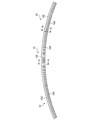
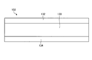
- FIG. 3 is a side view of the split ring according to the present embodiment.
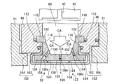
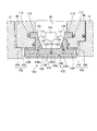
- FIG. 4 is a partially enlarged view showing the vicinity of the cross section of the split ring of the gas turbine according to the present embodiment.
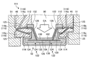
- FIG. 5 is a partially enlarged view showing the vicinity of the side surface of the split ring of the gas turbine according to the present embodiment.
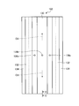
- FIG. 6 is a front view of the split ring support side member of the split ring according to the present embodiment.
- FIG. 7 is a top view of the split ring support side member of the split ring according to the present embodiment.
- FIG. 8 is a side view of the split ring support side member of the split ring according to the present embodiment.
- FIG. 9 is a cross-sectional view of the rotation direction end of the split ring support side member of the split ring according to the present embodiment.
- FIG. 10 is a perspective view of the split ring surface side member of the split ring according to the present embodiment.
- FIG. 11 is a front view of the split ring surface side member of the split ring according to the present embodiment.
- FIG. 12 is a top view of the split ring surface side member of the split ring according to the present embodiment.
- FIG. 13 is a partially enlarged view showing the vicinity of a side surface of a split ring of a gas turbine according to another embodiment.
- FIG. 14 is a partially enlarged view showing the vicinity of a side surface of a split ring of a gas turbine according to another embodiment.
- FIG. 15 is a partially enlarged view showing the vicinity of a side surface of a split ring of a gas turbine according to another embodiment.
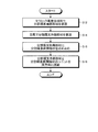
- FIG. 16 is a flowchart showing an example of a split ring manufacturing method.
- the gas turbine 1 includes a compressor 5, a combustor 6, and a turbine 7.
- a turbine shaft 8 is disposed through the center of the compressor 5, the combustor 6, and the turbine 7.
- the compressor 5, the combustor 6, and the turbine 7 are arranged in parallel along the axis CL of the turbine shaft 8 in order from the upstream side to the downstream side in the flow direction of air or combustion gas.
- Compressor 5 compresses air into compressed air.
- the compressor 5 is provided with a plurality of stages of compressor vanes 13 and a plurality of stages of compressor blades 14 in a compressor casing 12 having an air intake 11 for taking in air.
- a plurality of compressor vanes 13 at each stage are attached to the compressor casing 12 and arranged in parallel in the circumferential direction, and a plurality of compressor rotor blades 14 at each stage are attached to the turbine shaft 8 and arranged in parallel in the circumferential direction.
- the plurality of stages of compressor vanes 13 and the plurality of stages of compressor rotor blades 14 are alternately provided along the axial direction.
- the combustor 6 generates high-temperature and high-pressure combustion gas by supplying fuel to the compressed air compressed by the compressor 5.
- the combustor 6 covers, as a combustion cylinder, an inner cylinder 21 that mixes and burns compressed air and fuel, a tail cylinder 22 that guides combustion gas from the inner cylinder 21 to the turbine 7, and an outer periphery of the inner cylinder 21. 5 and an outer cylinder 23 for guiding the compressed air from 5 to the inner cylinder 21.
- the combustors 6 are arranged in the turbine casing 31 and a plurality of the combustors 6 are arranged in the circumferential direction. Note that the air compressed by the compressor 5 is temporarily stored in the vehicle compartment 24 surrounded by the turbine casing 31 and then supplied to the combustor 6.
- the turbine 7 generates rotational power by the combustion gas generated by the combustor 6.
- the turbine 7 is provided with a plurality of stages of turbine stationary blades 32 and a plurality of stages of turbine blades 33 in a turbine casing 31 serving as an outer shell.
- the turbine stationary blades 32 at each stage are attached to the turbine casing 31 and arranged in a plurality of annular shapes in the circumferential direction, and the turbine rotor blades 33 at each stage are disk-shaped discs centered on the axis CL of the turbine shaft 8. It is fixed to the outer periphery and is arranged in a plurality of rings in the circumferential direction.
- the plurality of stages of turbine stationary blades 32 and the plurality of stages of turbine rotor blades 33 are alternately provided in the axial direction.
- An exhaust chamber 34 having a diffuser portion 54 continuous with the turbine 7 is provided on the downstream side in the axial direction of the turbine casing 31 (see FIG. 1).
- the turbine shaft 8 has an end portion on the compressor 5 side supported by a bearing portion 37 and an end portion on the exhaust chamber 34 side supported by a bearing portion 38 so as to be rotatable about an axis CL.
- a drive shaft of a generator (not shown) is connected to the end of the turbine shaft 8 on the exhaust chamber 34 side.
- the turbine stationary blade 32 includes an outer shroud 51, an airfoil portion 53 extending radially inward from the outer shroud 51, and an inner shroud provided on the radially inner side of the airfoil portion 53 (see FIG. 2). (Not shown). Further, the turbine stationary blade 32 is supported from the turbine casing 31 via the heat shield ring 46 and the blade ring 45 and is on the fixed side. The plurality of stages of turbine stationary blades 32 are, in order from the upstream side in the combustion gas flow direction FG, the first turbine stationary blade 32a, the second turbine stationary blade 32b, the third turbine stationary blade 32c, and the fourth turbine stationary blade. 32d.
- the first turbine stationary blade 32a is integrally formed by an outer shroud 51a, an airfoil portion 53a, and an inner shroud (not shown).
- the second turbine stationary blade 32b is integrally formed by an outer shroud 51b, an airfoil portion 53b, and an inner shroud (not shown).
- the third turbine vane 32c is integrally formed by an outer shroud 51c, an airfoil portion 53c, and an inner shroud (not shown).
- the fourth turbine stationary blade 32d is integrally formed by an outer shroud 51d, an airfoil portion 53d, and an inner shroud (not shown).
- the plurality of stages of turbine blades 33 are arranged on the inner side in the radial direction so as to face the plurality of split rings 52.
- the turbine rotor blades 33 at each stage are provided with a predetermined gap from each divided ring 52 and are movable.
- the plurality of stages of turbine blades 33 are, in order from the upstream side in the flow direction FG of the combustion gas, the first turbine blade 33a, the second turbine blade 33b, the third turbine blade 33c, and the fourth turbine blade. 33d.
- the first turbine blade 33a is provided on the radially inner side of the first split ring 52a.
- the second turbine blade 33b, the third turbine blade 33c, and the fourth turbine blade 33d are provided on the radially inner side of the second divided ring 52b, the third divided ring 52c, and the fourth divided ring 52d. Yes.
- the plurality of stages of turbine stationary blades 32 and the plurality of stages of turbine blades 33 are arranged in order from the upstream side in the combustion gas flow direction FG, the first turbine stationary blade 32a, the first turbine rotor blade 33a, and the second turbine stationary blade 33.
- the blades 32b, the second turbine blades 33b, the third turbine blades 32c, the third turbine blades 33c, the fourth turbine blades 32d, and the fourth turbine blades 33d are arranged to face each other in the axial direction. It is provided as follows.
- the turbine casing 31 has a blade ring 45 that is disposed on the radially inner side and is supported from the turbine casing 31.
- the blade ring 45 is formed in an annular shape around the turbine shaft 8, is divided into a plurality of portions in the circumferential direction and the axial direction, and is supported from the turbine casing 31.
- the plurality of blade rings 45 are, in order from the upstream side of the combustion gas flow direction (axial direction) FG, the first blade ring 45a, the second blade ring 45b, the third blade ring 45c, and the fourth blade ring. 45d.
- a heat shield ring 46 is disposed on the radially inner side of the blade ring 45, and the turbine stationary blade 32 is supported from the blade ring 45 via the heat shield ring 46.
- the plurality of heat shield rings 46 are, in order from the upstream side of the combustion gas flow direction (axial direction) FG, the first heat shield ring 46a, the second heat shield ring 46b, the third heat shield ring 46c, and the fourth A heat shield ring 46d.
- a plurality of turbine stationary blades 32 and a plurality of split rings 52 are provided adjacent to each other in the axial direction.
- the plurality of turbine stationary blades 32 and the plurality of divided rings 52 are arranged in order from the upstream side in the flow direction FG of the combustion gas, the first turbine stationary blade 32a, the first divided ring 52a, the second turbine stationary blade 32b, and the second.
- the split ring 52b, the third turbine vane 32c, the third split ring 52c, the fourth turbine vane 32d, and the fourth split ring 52d are arranged, and are provided so as to face each other in the axial direction.
- first turbine vane 32a and the first split ring 52a are attached to the inside in the radial direction of the first blade ring 45a via the first heat shield ring 46a.
- second turbine stationary blade 32b and the second divided ring 52b are attached to the inside in the radial direction of the second blade ring 45b via the second heat shield ring 46b
- third turbine stationary blade 32c and the third divided ring 52b are attached.
- the ring 52c is attached to the inner side in the radial direction of the third blade ring 45c via the third heat shield ring 46c
- the fourth turbine stationary blade 32d and the fourth split ring 52d are connected via the fourth heat shield ring 46d. It is attached to the inner side in the radial direction of the four blade ring 45d.
- FIG. 3 is a side view of the split ring according to the present embodiment.
- FIG. 4 is a partially enlarged view showing the vicinity of the cross section of the split ring of the gas turbine according to the present embodiment.
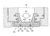
- FIG. 5 is a partially enlarged view showing the vicinity of the side surface of the split ring of the gas turbine according to the present embodiment. 4 is a cross-sectional view taken along line AA in FIG.
- FIG. 5 is a view taken along line BB in FIG.
- FIGS. 2 to 5 show only the split ring cooling structure around the second split ring 52b, but the other split rings have the same structure.
- the second split ring 52b will be described as the split ring 52 as a representative.
- a unit including the split ring 52 and the heat shield ring 46 is also referred to as a stationary side member unit.
- a plurality of split rings 52 are arranged in series in the rotation direction (the rotation direction of the gas turbine 1, the rotation direction of the turbine shaft 8, and the rotation direction of the turbine rotor blade 33).
- the plurality of split rings 52 have a ring shape arranged in the rotation direction. That is, one divided ring 52 has an arc shape when viewed from the rotation axis direction.
- the split ring 52 is disposed between the heat shield rings 46 and supported by the heat shield rings 46.
- the cooling air supplied to the split ring 52 is supplied from a blade ring cavity 41 surrounded by the casing 24 and the blade ring 45 of the turbine 7.
- a supply opening 47 is formed in the blade ring 45.
- a cavity 80 serving as a space is provided between the heat shield ring 46, the blade ring 45, and the split ring 52.
- the cavity 80 is annularly provided over the circumferential direction.
- the cavity 80 is communicated with the blade ring cavity 41 through the supply opening 47.
- the split ring 52 is formed with a cooling flow path communicating with the cavity 80.
- the cooling air CA supplied to the blade ring cavity 41 is supplied to the cavity 80 through the supply opening 47.
- the cooling air CA of the present embodiment uses passenger compartment air on the compressor outlet side or bleed air extracted from the compressor.
- the cooling air CA supplied to the cavity 80 is supplied to the split ring 52 and passes through the cooling flow path provided in the split ring 52, thereby cooling the split ring 52.
- the heat shield ring 46 is supported by the adjacent outer shroud 51.
- the heat shield ring 46 has a recess 110 into which a part of the split ring 52 is inserted on an end face in the combustion gas flow direction, that is, a face along a direction perpendicular to the rotation axis.
- the recess 110 is formed on the surface facing the cavity 80.
- the recess 110 extends in the direction of the rotation axis of the gas turbine 1, and the end of the recess 110 in the direction of the rotation axis of the gas turbine 1 serves as a bottom surface.
- the heat shield ring 46 includes a seal mechanism (second divided ring seal mechanism) 112 and a seal mechanism (first divided ring seal mechanism) 114 that seal the contact surface with the divided ring 52. Further, the heat shield ring 46 is provided with a seal groove 116 in which a seal plate 125 for sealing between the adjacent heat shield rings 46 is disposed.
- the seal groove 116 (116a, 116b, 116c) may supply seal air for urging the seal mechanisms 112, 114 toward the split ring 52 side. In the seal groove 116, a seal plate 125 is inserted into the seal groove 116b and the seal groove 116c.
- the seal plate 125 is inserted into the two seal grooves 116 b facing each other in the adjacent heat shield ring 46 and seals between the heat shield rings 46. Further, the seal plate 125 is inserted into two seal grooves 116 c facing each other of the adjacent heat shield rings 46 to seal between the heat shield rings 46.
- the seal grooves 116b and 116c, the seal plate 125 inserted into the seal grooves 116b and 116c, and the seal mechanisms 112 and 114 in contact with the seal plate 125 serve as side seal mechanisms.
- the seal mechanisms 112 and 114, the seal groove 116, and the seal plate 125 serve as the heat shield ring seal mechanism 111.
- the seal mechanism 112 is disposed on the bottom surface of the recess 110.
- the seal mechanism 112 is in contact with the surface of the split ring 52 that is orthogonal to the rotation axis of the gas turbine 1.
- the seal mechanism 114 is disposed on a surface along a direction orthogonal to the rotation axis of the heat shield ring 46 and at a position on the radially inner side of the gas turbine 1 with respect to the seal mechanism 112.
- the seal mechanism 114 is in contact with a surface of the split ring 52 that is orthogonal to the rotation axis of the gas turbine 1.
- the seal mechanisms 112 and 114 are formed of a material having heat resistance similar to that of the heat shield ring 46 and have elasticity.
- E seals can be used for the seal mechanisms 112 and 114.
- the sealing mechanisms 112 and 114 block the flow of air in the radial direction of the gas turbine at the installed positions.
- the seal groove 116 seals between the heat shield rings 46 by inserting the seal plate 125. Further, the seal groove 116 is branched into a plurality, and the ends of the branched portions face the seal mechanisms 112 and 114, respectively.
- the seal groove 116 includes seal grooves 116a, 116b, and 116c.
- the seal groove 116a is connected to a seal air supply source that supplies seal air.
- the seal groove 116b is connected to the seal groove 116a. One end portion of the seal groove 116 b faces the outer shroud 51, and the other end portion faces the seal mechanism 112.
- a seal mechanism is disposed at one end between the seal groove 116b and the outer shroud 51.
- the seal groove 116 c has one end connected to the seal groove 116 b and the other end facing the seal mechanism 114.
- the seal groove 116 is supplied with seal air having a pressure higher than that of the air supplied to the cavity 80.
- the combustion gas is prevented from leaking from the gap between the heat shield ring 46 and other members.
- the air supplied to the seal groove 116 urges the seal mechanisms 112 and 114 toward the split ring 52. Thereby, the space between the heat shield ring 46 and the split ring 52 is sealed, and the leakage of the cooling air CA from between the heat shield ring 46 and the split ring 52 can be suppressed.
- the seal mechanisms 112 and 114 have a structure in which a part of the seal air leaks when the seal air is supplied from the seal groove 116 even when the air leaks.
- the sealing mechanisms 112 and 114 of this embodiment provided the elastic member which contacts the target object sealed in a groove shape and seals, it is not limited to this, It is good also as only a groove
- the split ring 52 has basically the same shape in the cross section in the rotation direction (surface orthogonal to the rotation direction).
- the split ring 52 includes a split ring support side member 102 and a split ring surface side member 104.
- the split ring support side member 102 is connected to the heat shield ring 46.
- the split ring support side member 102 is supported by the heat shield ring 46.
- the split ring surface side member 104 is arranged on the inner side in the radial direction of the gas turbine 1 (the radial direction of the turbine shaft 8) than the split ring support side member 102, and is supported by the split ring support side member 102.
- the split ring surface side member 104 is exposed to the flow path through which the combustion gas flows, and faces the turbine rotor blade 33.
- a cooling channel 120 is provided between the split ring support side member 102 and the split ring surface side member 104.
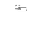
- FIG. 6 is a front view of the split ring support side member of the split ring according to the present embodiment.
- FIG. 7 is a top view of the split ring support side member of the split ring according to the present embodiment.
- FIG. 8 is a side view of the split ring support side member of the split ring according to the present embodiment.
- FIG. 9 is a cross-sectional view of the rotation direction end of the split ring support side member of the split ring according to the present embodiment. 9 is a cross-sectional view taken along the line CC of FIG. 6 to 9, the shape of the gas turbine 1 in the circumferential direction is shown by a straight line, but it has an arc shape as shown in FIG. 3.
- the split ring support side member (also simply referred to as “support side member”) 102 is a stationary part of the gas turbine 1 and supports the split ring surface side member 104.
- the support side member 102 is formed of a metal, for example, a heat resistant nickel alloy.
- the support side member 102 is an integrally molded component, and includes a main body 130, a first protrusion (first engagement portion) 132, and a second protrusion (second engagement portion) 134. .
- the end surface on the radially inner side of the gas turbine 1 becomes a facing portion (facing surface) 135.
- a channel resistance adjusting mechanism 122 is formed in the facing portion 135.
- the support side member 102 has through holes 136a, 136b, and 136c.
- the main body 130 is a plate-like member having a recess on the cavity 80 side, as shown in FIGS.
- the main body 130 has a shape having a recess, so that the area in contact with the cavity 80 can be increased.
- the first protrusions 132 are respectively provided at both ends of the main body 130 in the axial direction of the gas turbine 1.
- the first protrusion 132 protrudes more on the axial direction side of the gas turbine 1 than the main body 130.
- the first protrusion 132 is inserted into the recess 110 of the heat shield ring 46.
- the first protrusion 132 is in contact with the seal mechanism 112 at the end of the gas turbine 1 in the axial direction, that is, the surface farthest from the main body 130.
- the second protrusion 134 is provided on the radially inner side of the gas turbine 1 with respect to the first protrusion 132 of the main body 130.
- the second protrusions 134 are provided at both ends of the main body 130 in the axial direction of the gas turbine 1.
- the 2nd projection part 134 turns into an engaging part with which the division
- the end surface on the radially inner side of the gas turbine 1 of the second projecting portion 134 and the end surface on the radially inner side of the main body portion 130 form a facing portion 135 in the same plane.
- the through holes 136a, 136b, and 136c are passages that connect the cavity 80 and the cooling flow path 120 formed between the support side member 102 and the split ring surface side member 104.
- the through holes 136a, 136b, and 136c are formed in the order of the through hole 136a, the through hole 136b, and the through hole 136c from the upstream side to the downstream side in the combustion gas flow direction. Further, the through holes 136 a, 136 b, and 136 c of the present embodiment are formed at positions that become the center of the support side member 102 in the rotation direction of the gas turbine 1.
- the seal grooves 138 and 139 are formed on the end surface of the support side member 102 in the rotation direction of the gas turbine 1.
- the seal groove 138 extends in a direction parallel to the axial direction of the gas turbine 1, one end is formed in one second protrusion 134, and the other end is formed in the other second protrusion 134. Is done.
- the seal groove 139 has one end in contact with the seal groove 138 and the other end formed in the other first protrusion 132.
- the seal groove 139 is formed to a position where the other end is in contact with the seal mechanism 112.
- the support-side member 102 is formed with a groove connected from the seal mechanism 112 to the seal mechanism 112 by the seal grooves 138 and 139. As shown in FIG.
- the seal plate 126 is inserted into the seal groove 138.
- the seal plate 128 is inserted into the seal groove 139.
- the seal plate 126 is inserted into the seal grooves 138 and 139 of the two opposing support side members 102 to seal between the support side members 102 in the rotation direction of the gas turbine 1.
- the seal plate 128 is in contact with the seal plate 126 and seals between the seal mechanism 112 and the seal mechanism 112 and between the adjacent support side members 102.
- the seal plate 126 and the seal plate 128 serve as a support side seal mechanism.
- the split ring 52 supports the seal mechanism 112 and the heat shield ring 46 between the heat shield ring 46 by sealing the space between the support side member 102 and the heat shield ring 46 with the seal plates 126 and 128. It can be sealed with the side member 102. Thereby, in the support side member 102, the cavity 80 and the flow path of the combustion gas are separated by the seal plate 126 at the end of the gas turbine 1 in the rotation direction.
- the side seal mechanism including the seal groove 116 b and the inserted seal plate 125 is a support side member side seal mechanism that forms a seal structure connected to the support side member 102 in contact with the seal mechanism 112.
- FIG. 10 is a perspective view of the split ring surface side member of the split ring according to the present embodiment.
- FIG. 11 is a front view of the split ring surface side member of the split ring according to the present embodiment.
- FIG. 12 is a top view of the split ring surface side member of the split ring according to the present embodiment.
- the split ring surface side member (also simply referred to as “surface side member”) 104 is formed of a ceramic matrix composite material (also referred to as “CMC”).
- CMC is a material whose strength is improved by combining inorganic particles, metal particles, whiskers, short fibers, long fibers, and the like with ceramics.
- CMC is suitable for a material of a split ring because it has a lower specific gravity and higher heat resistance than, for example, a nickel-base superalloy.
- CMC is broadly classified into an oxide type (for example, Al 2 O 3 (aluminum oxide)) and a non-oxide type (for example, SiC (silicon carbide)).
- SiC fibers are added to non-oxide type SiC ceramics.
- CMC in which is combined.
- the front surface side member 104 has a surface portion 150, a folded portion 152, and a protruding portion 154.
- the surface side member 104 is connected to the surface portion 150, the folded portion 152, and the protruding portion 154, and has a shape that can be formed by bending a single plate, for example.
- the surface portion 150 is a plate-like member extending in the rotation axis direction and the radial direction of the gas turbine 1.
- the surface portion 150 is a portion that is an end surface on the radially inner side of the gas turbine 1 of the split ring 52 and is a part of the gas flow path.
- the surface 170 is a surface 170 that is a radially inner surface of the gas turbine 1 and is exposed to the combustion gas flow path R1.
- the back surface 172 which is the surface opposite to the front surface 170, faces the facing portion 135. A space between the back surface 172 and the facing portion 135 becomes the cooling flow path 120.
- returning part 152 is provided in the both ends of the rotating shaft direction of the gas turbine 1 of the surface part 150, respectively.
- the folded portion 152 includes a first portion 162 and a second portion 164.
- One end of the first portion 162 is connected to the end of the surface portion 150 in the direction of the rotation axis of the gas turbine 1, and the other end is on the radially outer side of the gas turbine 1 than the one end. is there. That is, the first portion 162 extends outward in the radial direction of the gas turbine 1 from the end portion of the surface portion 150 in the rotation axis direction of the gas turbine 1.
- the second portion 164 has one end connected to the other end of the first portion 162, and the other end is closer to the surface-side member 104 in the rotation axis direction of the gas turbine 1 than the one end.
- the second portion 164 is disposed on the radially outer side of the gas turbine 1 than the second protrusion 134 of the support side member 102.
- the second portion 164 has a radially inner surface of the gas turbine 1 facing and in contact with a radially outer surface of the second projecting portion 134 of the gas turbine 1.
- the surface side member 104 is engaged with the second protrusion 134 of the support side member 102 at the surface portion 150 and the folded portion 152.
- the second portion 164 is in contact with the second protrusion 134
- the first portion 162 is not in contact with the first protrusion 132.
- the protruding portion 154 extends from the folded portion 152 to the outside in the radial direction of the gas turbine 1.
- the surface on the side of the center line 159 of the surface side member 104 in the rotation axis direction of the gas turbine 1 faces the support side member 102.
- the protrusion 154 faces the heat shield ring 46 at a surface on the end side of the surface side member 104 in the rotation axis direction of the gas turbine 1.
- the protrusion 154 is in contact with the seal mechanism 114 at the surface facing the heat shield ring 46. Thereby, the space between the protruding portion 154 and the heat shield ring 46 is sealed by the seal mechanism 114.
- the side seal mechanism including the seal groove 116 c and the inserted seal plate 125 is a side seal mechanism for the surface side member that forms a seal structure connected to the surface side member 104 in contact with the seal mechanism 114.
- the flow path resistance adjusting mechanism 122 is provided in the cooling flow path 120.
- the flow path resistance adjustment mechanism 122 adjusts the flow path resistance of the cooling flow path 120 and the ease of air flow, and the pressure of the cooling air in the cooling flow path 120 on the upstream side of the combustion gas flow of the gas turbine 1 is adjusted to the downstream side.
- the pressure is higher than the pressure of the cooling air in the cooling channel 120.
- the flow path resistance adjusting mechanism 122 includes two partition plates 124 and through holes 136a, 136b, and 136c.
- the partition plate 124 protrudes in a direction away from the facing portion 135, and the tip is in contact with the surface side member 104.
- One partition plate 124 is disposed between the through hole 136a and the through hole 136b, and the other partition plate 124 is disposed between the through hole 136b and the through hole 136c.
- the partition plate 124 extends from one end of the split ring 52 to the other end in the rotation direction of the gas turbine 1.
- the through holes 136a, 136b, and 136c have smaller diameters in the order of the through hole 136a, the through hole 136b, and the through hole 136c. That is, the through hole 136a has a larger diameter than the through hole 136b.
- the through hole 136b has a larger diameter than the through hole 136c.
- the diameter of the through-hole becomes smaller as it goes from upstream to downstream of the combustion gas flow.
- the flow path resistance adjusting mechanism 122 can set the flow path resistances of the three spaces of the cooling flow path 120 partitioned by the partition plate 124 to different resistances.
- the flow resistance of the gas turbine 1 on the upstream side of the combustion gas flow is smaller than that on the downstream side, so that the pressure loss is reduced and cooling air with higher pressure is supplied.
- the split ring cooling method will be described by explaining the flow path of the cooling air CA flowing through the split ring 52.
- the cooling air CA supplied to the cavity 80 passes through the through holes 136 a, 136 b, 136 c and is supplied to each of the cooling flow paths 120 partitioned by the partition plate 124. That is, the cooling air CA passes through the split ring support side member 102 and flows into the cooling flow path between the split ring support side member 102 and the split ring surface side member 104.
- the cooling air CA that has passed through the through holes 136a, 136b, and 136c flows in the cooling flow path 120 from the center in the rotation direction of the gas turbine 1 toward the end.
- the cooling air CA flows through the cooling flow path 120 in both directions along the rotation direction of the gas turbine 1, that is, in two directions away from the through holes 136a, 136b, and 136c in the rotation direction.
- the cooling air CA that has flowed into the cooling flow path 120 also flows into the cooling space between the axial side surface of the split ring support side member 102 and the first portion (side surface member) 162 of the split ring surface side member 104.
- the axially facing side surface of the split ring support side member 102 and the first portion 162 that is, the part facing the axial direction in the cooling channel 120 among the split ring support side member and the split ring surface side member. Can be cooled.
- the cooling air CA that has moved to the end of the split ring 52 in the rotation direction of the gas turbine 1 is discharged from the gap of the split ring 52 to the combustion gas flow path R1. That is, the cooling air CA that has moved to the end of the split ring 52 in the rotation direction of the gas turbine 1 is between the split ring surface side member 104 and the split ring surface side member 104 that is adjacent in the rotation direction. To be discharged. Further, the cooling air CA that has moved to the end of the split ring 52 in the rotational direction of the gas turbine 1 also flows between the split ring support side member 102 and the adjacent split ring support member 102, and Cool the sides in the direction of rotation. The split ring 52 is thus cooled by the flow of the cooling air CA.
- the split ring 52 is configured such that the split ring surface side member 104 formed of CMC is arranged on the inner side in the radial direction of the gas turbine 1 of the split ring support side member 102 formed of metal.
- the member 104 has a shape that forms the combustion gas passage R1, the heat resistance of the split ring 52 can be increased.
- the split ring 52 is provided with a seal groove 138 and a seal plate 126 on the radially inner side of the end portion of the folded portion 152 on the radially outer side of the gas turbine 1, thereby shortening the distance between the cavity 80 and the cooling flow path 120. be able to. Thereby, the division
- the split ring 52 is provided with a protruding portion 154 on the split ring surface side member 104, and a sealing mechanism 114 is provided between the protruding portion 154 and the heat shield ring 46, and sealing is performed, so that the sealing mechanism has a ring shape. It is possible to improve the sealing performance while simplifying the installation. Since the sealing property can be enhanced, air leakage can be suppressed and each air can be used efficiently. Specifically, the amount of air leaking into the combustion gas flow path can be reduced while appropriately cooling the split ring 52. Thereby, the quantity of the compressed air used for cooling air can be reduced, and the quantity of the leakage air which lowers the temperature of combustion gas can also be reduced, and the efficiency of the gas turbine 1 can be improved.
- the split ring 52 has a cooling passage between the back surface 172 and the facing portion 135, the second portion 164 of the folded portion 152 is in contact with the second protruding portion 134, and the first portion 162 is not in contact with the first protruding portion 132.
- the part which contacts the surface side member 104 of the support side member 102 can be made into the position far from a combustion gas flow path. Thereby, the temperature around the part where the support side member 102 and the surface side member 104 contact can be lowered, and the temperature rise of the support side member 102 can be suppressed. Moreover, it can suppress that the support side member 102 and the surface side member 104 contact in the position where temperature is high.
- the split ring 52 is provided with a flow path resistance adjusting mechanism 122, and by adjusting the pressure balance of the cooling air flowing through the cooling flow path 120, the cooling air CA can be efficiently flowed, and the amount of the cooling air CA can be reduced. Can be reduced.
- the split ring 52 is a flow path resistance adjusting mechanism 122 that converts the pressure of the cooling air flowing through the cooling flow path 120 on the upstream side in the combustion gas flow direction of the gas turbine 1 to the cooling space on the downstream side in the combustion gas flow direction. By making it higher than the pressure of the cooling air flowing through the cooling air CA, it is possible to efficiently flow the cooling air CA.
- the split ring 52 is provided with a partition plate (partition part) 124 as the flow path resistance adjusting mechanism 122, and the cooling flow path 120 is separated into a plurality of spaces in a cross section orthogonal to the rotation direction, whereby the flow direction of the combustion gas ,
- the cooling flow path 120 can be separated, and the pressure of the cooling air can be easily changed depending on the position in the flow direction of the combustion gas.
- the split ring 52 can simplify the structure of the split ring surface side member 104 by providing the partition plate 124 on the split ring support side member 102. Further, the split ring 52 can be manufactured easily by forming the split ring surface side member 104 in a shape that allows the cross section to be drawn with one stroke as in the present embodiment, that is, by bending a single plate. .
- the split ring 52 is provided with through holes 136a, 136b, and 136c only in the vicinity of the center in the rotation direction of the gas turbine 1, and the split ring 52 is split by flowing the air flowing through the cooling flow path 120 along the rotation direction of the gas turbine 1.
- the ring support side member 102 and the split ring surface side member 104 can be cooled with an appropriate balance. Specifically, by using face-to-face cooling in which the air flowing through the cooling flow path 120 flows along the rotation direction of the gas turbine 1, it is possible to divide the cooling amount of the divided ring support side member 102 compared to the case of impingement cooling. The cooling amount of the ring surface side member 104 can be reduced. Thereby, the split ring 52 can suppress the excessive cooling of the split ring surface side member 104 formed of CMC and having high heat resistance while sufficiently cooling the split ring support side member 102 made of metal. .
- the split ring 52 has through-holes 136a, 136b, and 136c formed at the center of the support-side member 102 in the rotation direction of the gas turbine 1, and the center in the rotation direction of the gas turbine 1.
- the cooling air supplied to the cooling flow path 120 with the split ring surface side member 104 is changed in the rotational direction of the gas turbine 1. It can flow efficiently from the center to the end, and convection cooling can be performed efficiently.
- the center region is a region of (1/4) L from the center, and the end region is from the end. This is an area of (1/4) L.
- FIG. 13 is a partially enlarged view showing the vicinity of a side surface of a split ring of a gas turbine according to another embodiment.
- the split ring 52a shown in FIG. 13 is the same as the split ring 52 except for some shapes.
- the different points of the structure of the split ring will be described with emphasis, and parts having the same structure will be given the same reference numerals and description thereof will be omitted.
- the flow path resistance adjusting mechanism 122a is formed of a member different from the split ring support side member 102a and the split ring surface side member 104a.
- the flow path resistance adjusting mechanism 122 a includes a partition plate 180 and a buffer material 186.
- the split ring support side member 102a has a recess 182 at a position where the partition plate 180 is disposed.
- the recess 182 extends in the rotation direction of the gas turbine 1.
- the partition plate 180 is a plate that separates the cooling flow path 120 into a plurality of spaces, like the partition plate 124 of the flow path resistance adjusting mechanism 122.
- the partition plate 180 does not need to completely separate the space, and air may flow as long as the pressure difference can be maintained.
- the partition plate 180 is inserted into the recess 182 and protrudes toward the split ring surface side member 104a.
- the buffer material 186 is disposed between the partition plate 180 and the split ring surface side member 104a.
- the buffer material 186 is made of a material having heat resistance and a low reactivity with the CMC forming the split ring surface side member 104a, for example, a material other than metal.
- As the buffer material 186 for example, SiC felt can be used.
- the flow path resistance adjusting mechanism 122a may be a member different from the split ring support side member 102a and the split ring surface side member 104a. Thereby, manufacture of each member can be simplified.
- the split ring 52a is provided with a buffer material 186 made of a material having low reactivity with CMC as a reaction preventing layer between the partition plate 180 and the split ring surface side member 104a.
- the durability of the surface side member 104a can be increased.
- the surface portion 150 of the split ring surface side member 104a is in a high temperature because it contacts the combustion gas flow path.
- the surface part 150 which became high temperature is a metal which reacts when it contacts.
- the buffer material 186 it is possible to suppress reaction with other members even when the surface portion 150 becomes high temperature, and durability can be increased.
- the partition plate 180 may be formed of a material having heat resistance and low reactivity with the CMC forming the split ring surface side member 104a. . That is, the same effect can be obtained by forming the member in contact with the back surface 182 of the split ring surface side member 104a that is in contact with the CMC at a high temperature from a material having low reactivity with the CMC. Further, it is preferable to provide a cushioning material between the partition plate 124 of the split ring 52 and the surface portion 150. In this manner, the part of the partition plate (partition part) that contacts the surface opposite to the surface part of the split ring surface side member is made of a material other than metal, thereby protecting the split ring surface side member. , Durability can be increased.
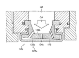
- FIG. 14 is a partially enlarged view showing the vicinity of a side surface of a split ring of a gas turbine according to another embodiment.
- the split ring 52b shown in FIG. 14 is the same as the split ring 52 except for some shapes.
- different points of the structure of the split ring 52b will be described with emphasis, and portions having the same structure will be denoted by the same reference numerals and description thereof will be omitted.
- the split ring 52b has a split ring support side member 102b and a split ring surface side member 104b.
- the split ring 52b includes a facing portion 135b in the flow path resistance adjusting mechanism 122b.
- the split ring 52b includes a structure in which the radial position of the gas turbine of the split ring support facing portion is different.
- the facing portion 135b of the split ring support side member 102b is inclined with respect to the back surface 172 of the split ring surface side member 104b.
- the facing portion 135b is inclined so as to approach the back surface 172 of the split ring surface side member 104b as it goes from upstream to downstream in the combustion gas flow direction.
- the split ring 52b is configured such that the flow path resistance adjusting mechanism 122b has a shape that approaches the back surface 172 of the split ring surface side member 104b as the facing portion 135b moves from upstream to downstream in the combustion gas flow direction. It can be set as the structure where a cooling flow path becomes narrow as it goes to the downstream from the upstream of a direction. Thereby, the flow path resistance adjusting mechanism 122b can increase the flow path resistance from the upstream in the combustion gas flow direction toward the downstream, and the pressure of the cooling air on the upstream side is made higher than the pressure of the cooling air on the downstream side. Can also be high.
- the flow path resistance adjusting mechanism 122b changes the inclination of the facing portion 135b, but may have a structure with different flow path resistances, and may change the surface roughness of the facing portion 135b. May be provided. Further, the flow path resistance adjusting mechanism 122b may change the flow path resistance in the direction of the rotation axis of the gas turbine 1. That is, the flow path resistance adjusting mechanism 122b may have a shape in which the height of the cooling flow path 120 decreases as it goes from the center in the rotation axis direction of the gas turbine 1 to the end. Further, the flow path resistance adjusting mechanism 122b may further include a partition plate. Further, in the flow path resistance adjusting mechanism 122b, the partition plate may have a shape whose width changes in the rotation axis direction of the gas turbine 1.
- the channel resistance adjusting mechanisms 122, 122a, 122b of the split rings 52, 52a, 52b disclosed in the present specification can be used singly or in combination.
- the split rings 52, 52a, 52b can increase the flow path resistance from the upstream to the downstream in the combustion gas flow direction by combining a plurality of flow resistance adjustment mechanisms 122, 122a, 122b. And the pressure of the cooling air on the upstream side can be made higher than the pressure of the cooling air on the downstream side.
- FIG. 15 is a partially enlarged view showing the vicinity of a side surface of a split ring of a gas turbine according to another embodiment.
- the split ring 52c shown in FIG. 15 is the same as the split ring 52 except for some shapes.
- different points of the structure of the split ring 52c will be described with emphasis, and portions having the same structure will be denoted by the same reference numerals and description thereof will be omitted.
- the split ring 52c has a split ring support side member 102c and a split ring surface side member 104c.
- the split ring surface side member 104c has the same structure as that of the split ring surface side member 104 except that the projecting portion 154 is not provided.
- the split ring support side member 102 c is in contact with the seal mechanism 114.
- the split ring 52c has a structure that does not include the projecting portion 154, so that the sealing performance is lowered. However, by adjusting the pressure by the flow path resistance adjusting mechanism 122, the seal air can be used efficiently.
- FIG. 16 is a flowchart illustrating an example of a method of manufacturing a split ring.
- the split ring surface side member 104 is manufactured with a ceramic matrix composite material (step S12). Further, the split ring surface side member 104 can be manufactured by a method of manufacturing a part manufactured from a ceramic matrix composite material.
- the split ring support side member 102 is manufactured with a metal (step S14). The split ring support side member 102 can be manufactured by performing machining such as casting, cutting, and polishing. Step S12 and step S14 may be executed in reverse order or in parallel. A plurality of split ring surface side members 104 and split ring surface side members 102 may be manufactured simultaneously.
- the split ring surface side member is fitted into the split ring support side member (step S16). Specifically, in the radial direction of the gas turbine 1, the second portion (projection) 164 of the split ring surface side member 104 is more radial than the second projection (projection) 134 of the split ring support side portion 102.
- the split ring surface side member 104 is fitted into the split ring support side member 102 at a position on the outer side, and a cooling channel 120 is formed between the split ring surface side member 104 and the split ring support side member 102.
- split ring support side member 102 and the split ring surface side member 104 move relative to the split ring support side member 102 and the split ring surface side member 104 in the extending direction (the direction along the rotation direction of the gas turbine at the time of installation). By doing so, the split ring surface side member 104 can be fitted into the split ring support side member 102.
- the split ring which is a unit of the split ring support side member 102 and the split ring surface side member 104 is connected in the circumferential direction (step S18).
- a ring shape is formed, and part of the outer peripheral surface of the flow path through which the combustion gas passes.
- a seal plate 126 is disposed between the adjacent split rings 52.
- the split ring support side member 102 is installed on the heat shield ring 46. After that, the split ring support side member 102 and the split ring surface side member 104 may be fitted together.
- the split ring 52 is a combination of the split ring support side member 102 and the split ring surface side member 104, and the second portion (projection) 164 of the split ring surface side member 104 is the split ring support side. It is easy to assemble the split ring surface side member 104 by fitting it into the split ring support side member 102 at a position that is more radially outward than the second protrusion (projection) 134 of the part 102. Can be manufactured.
Landscapes
- Engineering & Computer Science (AREA)
- Mechanical Engineering (AREA)
- General Engineering & Computer Science (AREA)
- Chemical & Material Sciences (AREA)
- Combustion & Propulsion (AREA)
- Turbine Rotor Nozzle Sealing (AREA)
Priority Applications (4)
| Application Number | Priority Date | Filing Date | Title |
|---|---|---|---|
| KR1020197019896A KR102238866B1 (ko) | 2017-01-12 | 2017-12-22 | 분할환 표면측 부재, 분할환 지지측 부재, 분할환, 정지측 부재 유닛, 가스 터빈, 분할환 냉각 방법 및 분할환 제조 방법 |
| CN201780083179.3A CN110177922B (zh) | 2017-01-12 | 2017-12-22 | 分割环表面侧构件、分割环支承侧构件、分割环、静止侧构件单元及方法 |
| US16/476,209 US11441447B2 (en) | 2017-01-12 | 2017-12-22 | Ring-segment surface-side member, ring-segment support-side member, ring segment, stationary-side member unit, and method |
| DE112017006797.9T DE112017006797B4 (de) | 2017-01-12 | 2017-12-22 | Ringsegment-oberflächenseitenelement für ein ringsegment einer gasturbine, ringsegment-tragseitenelement für ein ringsegment einer gasturbine, ringsegment, gasturbine, und ringsegment-kühlverfahren für ein ringsegment einer gasturbine |
Applications Claiming Priority (2)
| Application Number | Priority Date | Filing Date | Title |
|---|---|---|---|
| JP2017-003596 | 2017-01-12 | ||
| JP2017003596A JP6775428B2 (ja) | 2017-01-12 | 2017-01-12 | 分割環表面側部材、分割環支持側部材、分割環、静止側部材ユニット及び方法 |
Publications (1)
| Publication Number | Publication Date |
|---|---|
| WO2018131425A1 true WO2018131425A1 (ja) | 2018-07-19 |
Family
ID=62839977
Family Applications (1)
| Application Number | Title | Priority Date | Filing Date |
|---|---|---|---|
| PCT/JP2017/046068 WO2018131425A1 (ja) | 2017-01-12 | 2017-12-22 | 分割環表面側部材、分割環支持側部材、分割環、静止側部材ユニット及び方法 |
Country Status (6)
Families Citing this family (5)
| Publication number | Priority date | Publication date | Assignee | Title |
|---|---|---|---|---|
| EP3550106B1 (en) * | 2018-04-06 | 2024-10-09 | RTX Corporation | Cooling air for gas turbine engine with thermally isolated cooling air delivery |
| CN114294112B (zh) * | 2021-10-20 | 2023-06-13 | 中国航发四川燃气涡轮研究院 | 带转接密封结构的双通道管路装置 |
| KR102675092B1 (ko) | 2021-11-30 | 2024-06-12 | 두산에너빌리티 주식회사 | 링세그먼트 및 이를 포함하는 터빈 |
| US11913340B2 (en) * | 2022-06-17 | 2024-02-27 | Rtx Corporation | Air seal system with backside abradable layer |
| CN116733613B (zh) * | 2023-08-10 | 2023-10-20 | 成都中科翼能科技有限公司 | 一种燃气轮机的过渡段结构 |
Citations (6)
| Publication number | Priority date | Publication date | Assignee | Title |
|---|---|---|---|---|
| JP2000257447A (ja) * | 1999-03-03 | 2000-09-19 | Mitsubishi Heavy Ind Ltd | ガスタービン分割環 |
| US20030133790A1 (en) * | 2002-01-16 | 2003-07-17 | Darkins Toby George | Turbine shroud segment and shroud assembly |
| JP2004150325A (ja) * | 2002-10-30 | 2004-05-27 | Mitsubishi Heavy Ind Ltd | タービン翼環構造 |
| US20070077141A1 (en) * | 2005-10-04 | 2007-04-05 | Siemens Power Generation, Inc. | Ring seal system with reduced cooling requirements |
| JP2008111441A (ja) * | 2006-10-30 | 2008-05-15 | Snecma | ターボ機械のタービンのリングセクタ |
| JP2011208624A (ja) * | 2010-03-31 | 2011-10-20 | Hitachi Ltd | 高温部材の冷却構造 |
Family Cites Families (14)
| Publication number | Priority date | Publication date | Assignee | Title |
|---|---|---|---|---|
| JP3631898B2 (ja) * | 1998-03-03 | 2005-03-23 | 三菱重工業株式会社 | ガスタービンにおける分割環の冷却構造 |
| US6146091A (en) * | 1998-03-03 | 2000-11-14 | Mitsubishi Heavy Industries, Ltd. | Gas turbine cooling structure |
| US6758653B2 (en) | 2002-09-09 | 2004-07-06 | Siemens Westinghouse Power Corporation | Ceramic matrix composite component for a gas turbine engine |
| US7063503B2 (en) * | 2004-04-15 | 2006-06-20 | Pratt & Whitney Canada Corp. | Turbine shroud cooling system |
| JP2010065634A (ja) * | 2008-09-12 | 2010-03-25 | Hitachi Ltd | ガスタービンの高温部材 |
| US8292573B2 (en) * | 2009-04-21 | 2012-10-23 | General Electric Company | Flange cooled turbine nozzle |
| JP4634528B1 (ja) | 2010-01-26 | 2011-02-16 | 三菱重工業株式会社 | 分割環冷却構造およびガスタービン |
| KR20140015564A (ko) | 2010-04-20 | 2014-02-06 | 미츠비시 쥬고교 가부시키가이샤 | 분할 링 냉각 구조 |
| US9188062B2 (en) | 2012-08-30 | 2015-11-17 | Mitsubishi Hitachi Power Systems, Ltd. | Gas turbine |
| JP6466647B2 (ja) | 2014-03-27 | 2019-02-06 | 三菱日立パワーシステムズ株式会社 | ガスタービンの分割環の冷却構造及びこれを有するガスタービン |
| US10221715B2 (en) * | 2015-03-03 | 2019-03-05 | Rolls-Royce North American Technologies Inc. | Turbine shroud with axially separated pressure compartments |
| FR3036436B1 (fr) * | 2015-05-22 | 2020-01-24 | Safran Ceramics | Ensemble d'anneau de turbine avec maintien par brides |
| US9963990B2 (en) * | 2015-05-26 | 2018-05-08 | Rolls-Royce North American Technologies, Inc. | Ceramic matrix composite seal segment for a gas turbine engine |
| US10337346B2 (en) * | 2016-03-16 | 2019-07-02 | United Technologies Corporation | Blade outer air seal with flow guide manifold |
-
2017
- 2017-01-12 JP JP2017003596A patent/JP6775428B2/ja active Active
- 2017-12-22 WO PCT/JP2017/046068 patent/WO2018131425A1/ja active Application Filing
- 2017-12-22 KR KR1020197019896A patent/KR102238866B1/ko active Active
- 2017-12-22 DE DE112017006797.9T patent/DE112017006797B4/de active Active
- 2017-12-22 US US16/476,209 patent/US11441447B2/en active Active
- 2017-12-22 CN CN201780083179.3A patent/CN110177922B/zh active Active
Patent Citations (6)
| Publication number | Priority date | Publication date | Assignee | Title |
|---|---|---|---|---|
| JP2000257447A (ja) * | 1999-03-03 | 2000-09-19 | Mitsubishi Heavy Ind Ltd | ガスタービン分割環 |
| US20030133790A1 (en) * | 2002-01-16 | 2003-07-17 | Darkins Toby George | Turbine shroud segment and shroud assembly |
| JP2004150325A (ja) * | 2002-10-30 | 2004-05-27 | Mitsubishi Heavy Ind Ltd | タービン翼環構造 |
| US20070077141A1 (en) * | 2005-10-04 | 2007-04-05 | Siemens Power Generation, Inc. | Ring seal system with reduced cooling requirements |
| JP2008111441A (ja) * | 2006-10-30 | 2008-05-15 | Snecma | ターボ機械のタービンのリングセクタ |
| JP2011208624A (ja) * | 2010-03-31 | 2011-10-20 | Hitachi Ltd | 高温部材の冷却構造 |
Also Published As
| Publication number | Publication date |
|---|---|
| JP2018112144A (ja) | 2018-07-19 |
| KR102238866B1 (ko) | 2021-04-09 |
| DE112017006797B4 (de) | 2024-12-24 |
| KR20190092521A (ko) | 2019-08-07 |
| CN110177922A (zh) | 2019-08-27 |
| CN110177922B (zh) | 2022-05-27 |
| DE112017006797T5 (de) | 2019-09-26 |
| US11441447B2 (en) | 2022-09-13 |
| JP6775428B2 (ja) | 2020-10-28 |
| US20210140340A1 (en) | 2021-05-13 |
Similar Documents
| Publication | Publication Date | Title |
|---|---|---|
| WO2018131425A1 (ja) | 分割環表面側部材、分割環支持側部材、分割環、静止側部材ユニット及び方法 | |
| CA2606435C (en) | Cantilevered nozzle with crowned flange to improve outer band low cycle fatigue | |
| US8152450B1 (en) | Floating air seal for a turbine | |
| CN107075961B (zh) | 供用于涡轮发动机中的位于过渡道和第一排叶片组件之间的密封组件 | |
| US8388310B1 (en) | Turbine disc sealing assembly | |
| WO2015146854A1 (ja) | 分割環冷却構造及びこれを有するガスタービン | |
| CA2978395C (en) | Turbine | |
| KR20170077802A (ko) | 끝단부가 덮인 터빈 로터 블레이드 | |
| JP2011508151A (ja) | タービンノズルセグメントおよびタービンノズルアセンブリ | |
| JP2006342797A (ja) | ガスタービンエンジンのシールアッセンブリ、ロータアッセンブリ、ロータアッセンブリ用ブレードおよび段間キャビティシール | |
| RU2652736C2 (ru) | Роторное колесо, ротор газовой турбины и способ продувки ротора газовой турбины | |
| US9816389B2 (en) | Turbine rotor blades with tip portion parapet wall cavities | |
| JP5863894B2 (ja) | 動翼体及び回転機械 | |
| JP5675282B2 (ja) | 動翼体及び回転機械 | |
| JPH06102989B2 (ja) | タ―ビンノズルおよびシュラウドの隣接する円周方向セグメント間の隙間シ―ル構造 | |
| KR101737716B1 (ko) | 가스 터빈 및 외측 슈라우드 | |
| US20120269622A1 (en) | Turbine vane and gas turbine | |
| US11015481B2 (en) | Turbine shroud block segment with near surface cooling channels | |
| US11905886B2 (en) | Heatshield for a gas turbine engine | |
| CN110662885B (zh) | 轴流旋转机械 | |
| CN107438701A (zh) | 涡轮机翼型件的在两个压力下的冷却 | |
| RU2790234C1 (ru) | Тепловой экран для газотурбинного двигателя | |
| JP7234006B2 (ja) | 高温部品及び高温部品の製造方法 | |
| JP6726776B2 (ja) | ガスタービンの分割環の冷却構造及びこれを有するガスタービン | |
| KR20240167451A (ko) | 터빈 익환 조립체 및 터빈의 조립 방법 |
Legal Events
| Date | Code | Title | Description |
|---|---|---|---|
| 121 | Ep: the epo has been informed by wipo that ep was designated in this application |
Ref document number: 17891384 Country of ref document: EP Kind code of ref document: A1 |
|
| ENP | Entry into the national phase |
Ref document number: 20197019896 Country of ref document: KR Kind code of ref document: A |
|
| 122 | Ep: pct application non-entry in european phase |
Ref document number: 17891384 Country of ref document: EP Kind code of ref document: A1 |