EP3550106B1 - Cooling air for gas turbine engine with thermally isolated cooling air delivery - Google Patents
Cooling air for gas turbine engine with thermally isolated cooling air delivery Download PDFInfo
- Publication number
- EP3550106B1 EP3550106B1 EP19167088.4A EP19167088A EP3550106B1 EP 3550106 B1 EP3550106 B1 EP 3550106B1 EP 19167088 A EP19167088 A EP 19167088A EP 3550106 B1 EP3550106 B1 EP 3550106B1
- Authority
- EP
- European Patent Office
- Prior art keywords
- gas turbine
- rotating surface
- turbine engine
- downstream
- set forth
- Prior art date
- Legal status (The legal status is an assumption and is not a legal conclusion. Google has not performed a legal analysis and makes no representation as to the accuracy of the status listed.)
- Active
Links
Images


Classifications
-
- F—MECHANICAL ENGINEERING; LIGHTING; HEATING; WEAPONS; BLASTING
- F01—MACHINES OR ENGINES IN GENERAL; ENGINE PLANTS IN GENERAL; STEAM ENGINES
- F01D—NON-POSITIVE DISPLACEMENT MACHINES OR ENGINES, e.g. STEAM TURBINES
- F01D25/00—Component parts, details, or accessories, not provided for in, or of interest apart from, other groups
- F01D25/08—Cooling; Heating; Heat-insulation
-
- F—MECHANICAL ENGINEERING; LIGHTING; HEATING; WEAPONS; BLASTING
- F01—MACHINES OR ENGINES IN GENERAL; ENGINE PLANTS IN GENERAL; STEAM ENGINES
- F01D—NON-POSITIVE DISPLACEMENT MACHINES OR ENGINES, e.g. STEAM TURBINES
- F01D5/00—Blades; Blade-carrying members; Heating, heat-insulating, cooling or antivibration means on the blades or the members
- F01D5/02—Blade-carrying members, e.g. rotors
- F01D5/08—Heating, heat-insulating or cooling means
- F01D5/081—Cooling fluid being directed on the side of the rotor disc or at the roots of the blades
-
- F—MECHANICAL ENGINEERING; LIGHTING; HEATING; WEAPONS; BLASTING
- F01—MACHINES OR ENGINES IN GENERAL; ENGINE PLANTS IN GENERAL; STEAM ENGINES
- F01D—NON-POSITIVE DISPLACEMENT MACHINES OR ENGINES, e.g. STEAM TURBINES
- F01D25/00—Component parts, details, or accessories, not provided for in, or of interest apart from, other groups
- F01D25/08—Cooling; Heating; Heat-insulation
- F01D25/14—Casings modified therefor
- F01D25/145—Thermally insulated casings
-
- F—MECHANICAL ENGINEERING; LIGHTING; HEATING; WEAPONS; BLASTING
- F02—COMBUSTION ENGINES; HOT-GAS OR COMBUSTION-PRODUCT ENGINE PLANTS
- F02C—GAS-TURBINE PLANTS; AIR INTAKES FOR JET-PROPULSION PLANTS; CONTROLLING FUEL SUPPLY IN AIR-BREATHING JET-PROPULSION PLANTS
- F02C6/00—Plural gas-turbine plants; Combinations of gas-turbine plants with other apparatus; Adaptations of gas-turbine plants for special use
- F02C6/04—Gas-turbine plants providing heated or pressurised working fluid for other apparatus, e.g. without mechanical power output
- F02C6/06—Gas-turbine plants providing heated or pressurised working fluid for other apparatus, e.g. without mechanical power output providing compressed gas
- F02C6/08—Gas-turbine plants providing heated or pressurised working fluid for other apparatus, e.g. without mechanical power output providing compressed gas the gas being bled from the gas-turbine compressor
-
- F—MECHANICAL ENGINEERING; LIGHTING; HEATING; WEAPONS; BLASTING
- F02—COMBUSTION ENGINES; HOT-GAS OR COMBUSTION-PRODUCT ENGINE PLANTS
- F02C—GAS-TURBINE PLANTS; AIR INTAKES FOR JET-PROPULSION PLANTS; CONTROLLING FUEL SUPPLY IN AIR-BREATHING JET-PROPULSION PLANTS
- F02C7/00—Features, components parts, details or accessories, not provided for in, or of interest apart form groups F02C1/00 - F02C6/00; Air intakes for jet-propulsion plants
- F02C7/12—Cooling of plants
- F02C7/16—Cooling of plants characterised by cooling medium
- F02C7/18—Cooling of plants characterised by cooling medium the medium being gaseous, e.g. air
- F02C7/185—Cooling means for reducing the temperature of the cooling air or gas
-
- F—MECHANICAL ENGINEERING; LIGHTING; HEATING; WEAPONS; BLASTING
- F02—COMBUSTION ENGINES; HOT-GAS OR COMBUSTION-PRODUCT ENGINE PLANTS
- F02C—GAS-TURBINE PLANTS; AIR INTAKES FOR JET-PROPULSION PLANTS; CONTROLLING FUEL SUPPLY IN AIR-BREATHING JET-PROPULSION PLANTS
- F02C7/00—Features, components parts, details or accessories, not provided for in, or of interest apart form groups F02C1/00 - F02C6/00; Air intakes for jet-propulsion plants
- F02C7/24—Heat or noise insulation
-
- F—MECHANICAL ENGINEERING; LIGHTING; HEATING; WEAPONS; BLASTING
- F02—COMBUSTION ENGINES; HOT-GAS OR COMBUSTION-PRODUCT ENGINE PLANTS
- F02C—GAS-TURBINE PLANTS; AIR INTAKES FOR JET-PROPULSION PLANTS; CONTROLLING FUEL SUPPLY IN AIR-BREATHING JET-PROPULSION PLANTS
- F02C9/00—Controlling gas-turbine plants; Controlling fuel supply in air- breathing jet-propulsion plants
- F02C9/16—Control of working fluid flow
- F02C9/18—Control of working fluid flow by bleeding, bypassing or acting on variable working fluid interconnections between turbines or compressors or their stages
-
- F—MECHANICAL ENGINEERING; LIGHTING; HEATING; WEAPONS; BLASTING
- F05—INDEXING SCHEMES RELATING TO ENGINES OR PUMPS IN VARIOUS SUBCLASSES OF CLASSES F01-F04
- F05D—INDEXING SCHEME FOR ASPECTS RELATING TO NON-POSITIVE-DISPLACEMENT MACHINES OR ENGINES, GAS-TURBINES OR JET-PROPULSION PLANTS
- F05D2220/00—Application
- F05D2220/30—Application in turbines
- F05D2220/32—Application in turbines in gas turbines
-
- F—MECHANICAL ENGINEERING; LIGHTING; HEATING; WEAPONS; BLASTING
- F05—INDEXING SCHEMES RELATING TO ENGINES OR PUMPS IN VARIOUS SUBCLASSES OF CLASSES F01-F04
- F05D—INDEXING SCHEME FOR ASPECTS RELATING TO NON-POSITIVE-DISPLACEMENT MACHINES OR ENGINES, GAS-TURBINES OR JET-PROPULSION PLANTS
- F05D2230/00—Manufacture
- F05D2230/90—Coating; Surface treatment
-
- F—MECHANICAL ENGINEERING; LIGHTING; HEATING; WEAPONS; BLASTING
- F05—INDEXING SCHEMES RELATING TO ENGINES OR PUMPS IN VARIOUS SUBCLASSES OF CLASSES F01-F04
- F05D—INDEXING SCHEME FOR ASPECTS RELATING TO NON-POSITIVE-DISPLACEMENT MACHINES OR ENGINES, GAS-TURBINES OR JET-PROPULSION PLANTS
- F05D2240/00—Components
- F05D2240/60—Shafts
-
- F—MECHANICAL ENGINEERING; LIGHTING; HEATING; WEAPONS; BLASTING
- F05—INDEXING SCHEMES RELATING TO ENGINES OR PUMPS IN VARIOUS SUBCLASSES OF CLASSES F01-F04
- F05D—INDEXING SCHEME FOR ASPECTS RELATING TO NON-POSITIVE-DISPLACEMENT MACHINES OR ENGINES, GAS-TURBINES OR JET-PROPULSION PLANTS
- F05D2300/00—Materials; Properties thereof
- F05D2300/20—Oxide or non-oxide ceramics
- F05D2300/21—Oxide ceramics
- F05D2300/2118—Zirconium oxides
-
- F—MECHANICAL ENGINEERING; LIGHTING; HEATING; WEAPONS; BLASTING
- F05—INDEXING SCHEMES RELATING TO ENGINES OR PUMPS IN VARIOUS SUBCLASSES OF CLASSES F01-F04
- F05D—INDEXING SCHEME FOR ASPECTS RELATING TO NON-POSITIVE-DISPLACEMENT MACHINES OR ENGINES, GAS-TURBINES OR JET-PROPULSION PLANTS
- F05D2300/00—Materials; Properties thereof
- F05D2300/20—Oxide or non-oxide ceramics
- F05D2300/22—Non-oxide ceramics
-
- F—MECHANICAL ENGINEERING; LIGHTING; HEATING; WEAPONS; BLASTING
- F05—INDEXING SCHEMES RELATING TO ENGINES OR PUMPS IN VARIOUS SUBCLASSES OF CLASSES F01-F04
- F05D—INDEXING SCHEME FOR ASPECTS RELATING TO NON-POSITIVE-DISPLACEMENT MACHINES OR ENGINES, GAS-TURBINES OR JET-PROPULSION PLANTS
- F05D2300/00—Materials; Properties thereof
- F05D2300/60—Properties or characteristics given to material by treatment or manufacturing
- F05D2300/614—Fibres or filaments
-
- Y—GENERAL TAGGING OF NEW TECHNOLOGICAL DEVELOPMENTS; GENERAL TAGGING OF CROSS-SECTIONAL TECHNOLOGIES SPANNING OVER SEVERAL SECTIONS OF THE IPC; TECHNICAL SUBJECTS COVERED BY FORMER USPC CROSS-REFERENCE ART COLLECTIONS [XRACs] AND DIGESTS
- Y02—TECHNOLOGIES OR APPLICATIONS FOR MITIGATION OR ADAPTATION AGAINST CLIMATE CHANGE
- Y02T—CLIMATE CHANGE MITIGATION TECHNOLOGIES RELATED TO TRANSPORTATION
- Y02T50/00—Aeronautics or air transport
- Y02T50/60—Efficient propulsion technologies, e.g. for aircraft
Definitions
- This application relates to the supply of cooled cooling air to various rotating components in a gas turbine engine and wherein a cooling air path is thermally isolated from hotter sections of the gas turbine engine.
- Gas turbine engines typically include a fan delivering air into a bypass duct as bypass air and into a compressor in a core engine.
- the air in the compressor is compressed and delivered into a combustor where it is mixed with fuel and ignited. Products of this combustion pass downstream over turbine rotors driving them to rotate.
- the present invention provides a gas turbine engine in accordance with claim 1.
- FIG. 1 schematically illustrates a gas turbine engine 20.
- the gas turbine engine 20 is disclosed herein as a two-spool turbofan that generally incorporates a fan section 22, a compressor section 24, a combustor section 26 and a turbine section 28.
- the fan section 22 drives air along a bypass flow path B in a bypass duct defined within a nacelle 15, and also drives air along a core flow path C for compression and communication into the combustor section 26 then expansion through the turbine section 28.
- FIG. 1 schematic
- the exemplary engine 20 generally includes a low speed spool 30 and a high speed spool 32 mounted for rotation about an engine central longitudinal axis A relative to an engine static structure 36 via several bearing systems 38. It should be understood that various bearing systems 38 at various locations may alternatively or additionally be provided, and the location of bearing systems 38 may be varied as appropriate to the application.
- the low speed spool 30 generally includes an inner shaft 40 that interconnects a fan 42, a first (or low) pressure compressor 44 and a first (or low) pressure turbine 46.
- the inner shaft 40 is connected to the fan 42 through a speed change mechanism, which in exemplary gas turbine engine 20 is illustrated as a geared architecture 48 to drive the fan 42 at a lower speed than the low speed spool 30.
- the high speed spool 32 includes an outer shaft 50 that interconnects a second (or high) pressure compressor 52 and a second (or high) pressure turbine 54.
- a combustor 56 is arranged in exemplary gas turbine 20 between the high pressure compressor 52 and the high pressure turbine 54.
- a mid-turbine frame 57 of the engine static structure 36 is arranged generally between the high pressure turbine 54 and the low pressure turbine 46.
- the mid-turbine frame 57 further supports bearing systems 38 in the turbine section 28.
- the inner shaft 40 and the outer shaft 50 are concentric and rotate via bearing systems 38 about the engine central longitudinal axis A which is collinear with their longitudinal axes.
- the core airflow is compressed by the low pressure compressor 44 then the high pressure compressor 52, mixed and burned with fuel in the combustor 56, then expanded over the high pressure turbine 54 and low pressure turbine 46.
- the mid-turbine frame 57 includes airfoils 59 which are in the core airflow path C.
- the turbines 46, 54 rotationally drive the respective low speed spool 30 and high speed spool 32 in response to the expansion.
- gear system 48 may be located aft of combustor section 26 or even aft of turbine section 28, and fan section 22 may be positioned forward or aft of the location of gear system 48.
- the engine 20 in one example is a high-bypass geared aircraft engine.
- the engine 20 bypass ratio is greater than about six (6), with an example embodiment being greater than about ten (10)
- the geared architecture 48 is an epicyclic gear train, such as a planetary gear system or other gear system, with a gear reduction ratio of greater than about 2.3
- the low pressure turbine 46 has a pressure ratio that is greater than about five.
- the engine 20 bypass ratio is greater than about ten (10:1)
- the fan diameter is significantly larger than that of the low pressure compressor 44
- the low pressure turbine 46 has a pressure ratio that is greater than about five 5:1.
- Low pressure turbine 46 pressure ratio is pressure measured prior to inlet of low pressure turbine 46 as related to the pressure at the outlet of the low pressure turbine 46 prior to an exhaust nozzle.
- the geared architecture 48 may be an epicycle gear train, such as a planetary gear system or other gear system, with a gear reduction ratio of greater than about 2.3:1. It should be understood, however, that the above parameters are only exemplary of one embodiment of a geared architecture engine and that the present invention is applicable to other gas turbine engines including direct drive turbofans.
- the fan section 22 of the engine 20 is designed for a particular flight condition -- typically cruise at about 0.8 Mach and about 35,000 feet (10,668 meters).
- the flight condition of 0.8 Mach and 35,000 ft (10,668 meters), with the engine at its best fuel consumption - also known as "bucket cruise Thrust Specific Fuel Consumption ('TSFC')" - is the industry standard parameter of lbm of fuel being burned divided by lbf of thrust the engine produces at that minimum point.
- "Low fan pressure ratio” is the pressure ratio across the fan blade alone, without a Fan Exit Guide Vane (“FEGV”) system.
- the low fan pressure ratio as disclosed herein according to one non-limiting embodiment is less than about 1.45.
- the "Low corrected fan tip speed” as disclosed herein according to one non-limiting embodiment is less than about 1150 ft / second (350.5 meters/second).
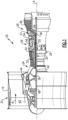
- FIG. 2 shows an intercooled cooling air system 100.
- a high pressure compressor 102 is provided with a tap 104 for tapping air to be utilized as cooling air.
- the tap 104 is from an intermediate location in the high pressure compressor. In alternative embodiments, the tap could be from a low pressure compressor.
- the tap in the Figure 2 embodiment is from a location upstream of a downstream most location 105 in the high pressure compressor 102.
- the tapped air at line 104 passes through a first leg 106 of a heat exchanger and back into a second leg 108 where it is returned through an inner housing 109.
- the heat exchanger 106/108 sits in a chamber 110 in this embodiment, which is radially inward of the bypass duct B.
- a valve 112 selectively allows the air from bypass duct B to pass over the heat exchanger 106/108.
- a control 114 is shown controlling the position of the valve 112. Air at line 116 inward of the housing 109 passes through a shutoff valve 118 into a cooling compressor 120.
- the cooling compressor 120 is provided with a drive 121.
- a system to stop the cooling compressor 120 from compressing is provided.
- the system is a clutch 122 which can disconnect the cooling compressor 120 from its drive 121.
- the drive 121 could be an electric motor and simply stopped.
- the control 114 controls the shutoff valve 118 and the clutch 122. It is desirable that the control be programmed such that the compression of air by the cooling compressor 120 is effectively stopped before the valve 118 is shut down to block the flow of air from line 116 reaching the cooling compressor 120.
- the air Downstream of the cooling compressor 120, the air passes into a line 124 and through struts 128 in a diffuser 126 radially into a mixing chamber 130.
- high pressure air may be tapped at 132 into the mixing chamber 130.
- the high pressure air tapped 132 may be air downstream of the downstream most location 105 in the high pressure compressor 102.
- the air from the mixing chamber 130 is shown passing to cool a disk and rim 142 of a downstream most location in the high pressure compressor 102.
- the air is also shown passing between a fixed housing 136 and a rotating shaft portion 140, which is part of the high pressure spool as described with regard to Figure 1 .
- a chamber 141 between the housing 136 and outer periphery of the shaft portion 140 receives the cooling airflow. That air passes through a tangential on-board injector 144 ("TOBI”) and then passes to cool the first stage blade 146 and vane 148 of a high pressure turbine.
- TOBI tangential on-board injector
- the wall 136 is radially inward of a combustor 134 and a chamber 138 is intermediate to the two.
- the chamber 138 receives air downstream of the downstream most location in the high pressure compressor and, thus, is at high temperature. As the air passes to the TOBI 144 and through the chamber 141, it may be heated by those high temperatures, which reduces the efficiency of the overall system.
- an insulation feature is placed both on at least a majority of the surface area of the housing 136 between the diffuser 126 and the TOBI 144.
- An insulation material is also placed along the majority of the outer surface of the shaft portion 140 between the downstream most location of the high pressure compressor and the rotation of the first turbine blade 146.
- each of the housing 136 and shaft 140 are formed of an underlying base metal and an outer insulation material.
- the outer insulation material has better resistance to heat passage than does the underlying metal.
- Insulation in a gas turbine and as may be defined in this application is a non-structural addition to a structure in that there is little or no structural contribution to the additional aspect involved. Further, the insulation in a gas turbine, may prevent fluid from passing on one side of the lower conductivity material which is sometimes referred to as "infiltration.” Such fluid passage would dramatically lower the value of the measures taken to apply the insulation. And, finally, the insulation may be introduced to the assembly by additional manufacturing steps and processes.
- the cooling system 200 taps air from a location at or downstream of the downstream most location 204 in the high pressure compressor 202.
- the air is shown tapped at 206 from a chamber radially outward of the combustor 208. That air passes through a heat exchanger 210, which is shown schematically being cooled, and then returned back inwardly through chamber 212 to the high pressure turbine 214.
- Such passage of air may also include the wall 136 and shaft 140 as in the Figure 2 embodiment.
- the same temperature challenges are raised.
- Figure 4 shows details of one embodiment of insulation material.
- the outer surface of the shaft 140 which faces the wall 136, is preferably provided with an insulation coating. Coating is preferred for the rotating structure as the attachment of sheets or other structure which might require mechanical attachment raises challenges with the centrifugal forces that the rotating structure will see.
- the underlying base metal 150 is provided with a metallic bond coat 152.
- a thermally-grown oxide coating 154 is placed outwardly of the bond coat 152.
- a ceramic topcoat 156 then surrounds the thermally-grown oxide.
- the ceramic topcoat 156 is composed of Yttria-stabilized zirconia.
- An outer surface of the housing 136 includes the metallic base layer 160 and a double wall structure, such as provided by an attached outer wall 164, which faces the rotating shaft surface 140.
- An intermediate insulation material such as a ceramic fiber blanket 162 is placed between the walls 160 and 164.
- Ceramic fiber blankets are known for various applications and may be formed of bulk fibers produced by spinning processes.
- the blanket 162 may be formed from pure alumina-silica. Further, the blanket 162 may be a continuous blanket and may be mechanically sewn with double needles to provide better integrity to the surface on both sides of the blanket.
- the pipes and, particularly, those downstream of the heat exchanger 106/108 (or 210) may also be provided with insulation. This would include connections 116 and, in particular, connection 124.
- monitors are provided to ensure proper operation of valve 112, valve 118, clutch 122, and predetermine any undesirable pressures or temperatures in the conduit 124.
- a gas turbine engine includes rotatable components including components within a compressor section and a turbine section housed within an outer housing.
- a tap is connected to tap air that has passed at least partially through the compressor section.
- the tap is connected to pass through a heat exchanger and connected to pass into a flow path between a rotating surface and a non-rotating surface.
- the flow path is connected to cool at least one of said rotatable components.
- At least a portion of each of the non-rotating surface and the rotating surface are provided with a base metal, and an insulation material on a surface facing the other of the rotatable and non-rotatable surfaces.
Landscapes
- Engineering & Computer Science (AREA)
- Chemical & Material Sciences (AREA)
- Combustion & Propulsion (AREA)
- Mechanical Engineering (AREA)
- General Engineering & Computer Science (AREA)
- Physics & Mathematics (AREA)
- Fluid Mechanics (AREA)
- Structures Of Non-Positive Displacement Pumps (AREA)
Description
- This application relates to the supply of cooled cooling air to various rotating components in a gas turbine engine and wherein a cooling air path is thermally isolated from hotter sections of the gas turbine engine.
- Gas turbine engines are known and typically include a fan delivering air into a bypass duct as bypass air and into a compressor in a core engine. The air in the compressor is compressed and delivered into a combustor where it is mixed with fuel and ignited. Products of this combustion pass downstream over turbine rotors driving them to rotate.
- As can be appreciated, many of the components in a gas turbine engine see very high temperatures. As an example, the turbine section and, in particular, its early stages see hot products of combustion. In addition, the compressor and, in particular, its downstream most stages also see very high temperatures. This is particularly true as the pressures developed in the compressor sections are increasing.
- Thus, it is known to supply cooling air to various rotating components such as in the turbine section and/or compressor section.
- A prior art gas turbine having the features of the preamble to claim 1 is disclosed in
US 6,612,114 . DocumentGB 2 348 466 - The present invention provides a gas turbine engine in accordance with claim 1.
- Features of embodiments are recited in the dependent claims.
- These and other features may be best understood from the following drawings and specification.
-
-
Figure 1 schematically shows a gas turbine engine. -
Figure 2 shows a first cooling air supply system. -
Figure 3 shows an alternative system. -
Figure 4 shows a detail of theFigure 2 or3 system. -
Figure 1 schematically illustrates agas turbine engine 20. Thegas turbine engine 20 is disclosed herein as a two-spool turbofan that generally incorporates afan section 22, acompressor section 24, acombustor section 26 and aturbine section 28. Thefan section 22 drives air along a bypass flow path B in a bypass duct defined within anacelle 15, and also drives air along a core flow path C for compression and communication into thecombustor section 26 then expansion through theturbine section 28. Although depicted as a two-spool turbofan gas turbine engine in the disclosed non-limiting embodiment, it should be understood that the concepts described herein are not limited to use with two-spool turbofans as the teachings may be applied to other types of turbine engines including three-spool architectures. - The
exemplary engine 20 generally includes alow speed spool 30 and ahigh speed spool 32 mounted for rotation about an engine central longitudinal axis A relative to an enginestatic structure 36 viaseveral bearing systems 38. It should be understood thatvarious bearing systems 38 at various locations may alternatively or additionally be provided, and the location ofbearing systems 38 may be varied as appropriate to the application. - The
low speed spool 30 generally includes aninner shaft 40 that interconnects afan 42, a first (or low)pressure compressor 44 and a first (or low)pressure turbine 46. Theinner shaft 40 is connected to thefan 42 through a speed change mechanism, which in exemplarygas turbine engine 20 is illustrated as a gearedarchitecture 48 to drive thefan 42 at a lower speed than thelow speed spool 30. Thehigh speed spool 32 includes anouter shaft 50 that interconnects a second (or high)pressure compressor 52 and a second (or high)pressure turbine 54. Acombustor 56 is arranged inexemplary gas turbine 20 between thehigh pressure compressor 52 and thehigh pressure turbine 54. Amid-turbine frame 57 of the enginestatic structure 36 is arranged generally between thehigh pressure turbine 54 and thelow pressure turbine 46. Themid-turbine frame 57 further supports bearingsystems 38 in theturbine section 28. Theinner shaft 40 and theouter shaft 50 are concentric and rotate viabearing systems 38 about the engine central longitudinal axis A which is collinear with their longitudinal axes. - The core airflow is compressed by the
low pressure compressor 44 then thehigh pressure compressor 52, mixed and burned with fuel in thecombustor 56, then expanded over thehigh pressure turbine 54 andlow pressure turbine 46. Themid-turbine frame 57 includesairfoils 59 which are in the core airflow path C. Theturbines low speed spool 30 andhigh speed spool 32 in response to the expansion. It will be appreciated that each of the positions of thefan section 22,compressor section 24,combustor section 26,turbine section 28, and fandrive gear system 48 may be varied. For example,gear system 48 may be located aft ofcombustor section 26 or even aft ofturbine section 28, andfan section 22 may be positioned forward or aft of the location ofgear system 48. - The
engine 20 in one example is a high-bypass geared aircraft engine. In a further example, theengine 20 bypass ratio is greater than about six (6), with an example embodiment being greater than about ten (10), the gearedarchitecture 48 is an epicyclic gear train, such as a planetary gear system or other gear system, with a gear reduction ratio of greater than about 2.3 and thelow pressure turbine 46 has a pressure ratio that is greater than about five. In one disclosed embodiment, theengine 20 bypass ratio is greater than about ten (10:1), the fan diameter is significantly larger than that of thelow pressure compressor 44, and thelow pressure turbine 46 has a pressure ratio that is greater than about five 5:1.Low pressure turbine 46 pressure ratio is pressure measured prior to inlet oflow pressure turbine 46 as related to the pressure at the outlet of thelow pressure turbine 46 prior to an exhaust nozzle. The gearedarchitecture 48 may be an epicycle gear train, such as a planetary gear system or other gear system, with a gear reduction ratio of greater than about 2.3:1. It should be understood, however, that the above parameters are only exemplary of one embodiment of a geared architecture engine and that the present invention is applicable to other gas turbine engines including direct drive turbofans. - A significant amount of thrust is provided by the bypass flow B due to the high bypass ratio. The
fan section 22 of theengine 20 is designed for a particular flight condition -- typically cruise at about 0.8 Mach and about 35,000 feet (10,668 meters). The flight condition of 0.8 Mach and 35,000 ft (10,668 meters), with the engine at its best fuel consumption - also known as "bucket cruise Thrust Specific Fuel Consumption ('TSFC')" - is the industry standard parameter of lbm of fuel being burned divided by lbf of thrust the engine produces at that minimum point. "Low fan pressure ratio" is the pressure ratio across the fan blade alone, without a Fan Exit Guide Vane ("FEGV") system. The low fan pressure ratio as disclosed herein according to one non-limiting embodiment is less than about 1.45. "Low corrected fan tip speed" is the actual fan tip speed in ft/sec divided by an industry standard temperature correction of [(Tram °R) / (518.7 °R)]0.5 (where
-
Figure 2 shows an intercooledcooling air system 100. Ahigh pressure compressor 102 is provided with atap 104 for tapping air to be utilized as cooling air. Note thetap 104 is from an intermediate location in the high pressure compressor. In alternative embodiments, the tap could be from a low pressure compressor. - Stated broadly, the tap in the
Figure 2 embodiment is from a location upstream of a downstreammost location 105 in thehigh pressure compressor 102. The tapped air atline 104 passes through afirst leg 106 of a heat exchanger and back into asecond leg 108 where it is returned through aninner housing 109. Theheat exchanger 106/108 sits in achamber 110 in this embodiment, which is radially inward of the bypass duct B. - As shown, a
valve 112 selectively allows the air from bypass duct B to pass over theheat exchanger 106/108. Acontrol 114 is shown controlling the position of thevalve 112. Air atline 116 inward of thehousing 109 passes through ashutoff valve 118 into acooling compressor 120. Thecooling compressor 120 is provided with adrive 121. - A system to stop the
cooling compressor 120 from compressing is provided. In the illustrated example, the system is aclutch 122 which can disconnect thecooling compressor 120 from itsdrive 121. Alternatively, thedrive 121 could be an electric motor and simply stopped. Thecontrol 114 controls theshutoff valve 118 and the clutch 122. It is desirable that the control be programmed such that the compression of air by thecooling compressor 120 is effectively stopped before thevalve 118 is shut down to block the flow of air fromline 116 reaching thecooling compressor 120. - Downstream of the
cooling compressor 120, the air passes into aline 124 and throughstruts 128 in adiffuser 126 radially into a mixingchamber 130. In this embodiment, high pressure air may be tapped at 132 into the mixingchamber 130. The high pressure air tapped 132 may be air downstream of the downstreammost location 105 in thehigh pressure compressor 102. The air from the mixingchamber 130 is shown passing to cool a disk andrim 142 of a downstream most location in thehigh pressure compressor 102. The air is also shown passing between afixed housing 136 and arotating shaft portion 140, which is part of the high pressure spool as described with regard toFigure 1 . Achamber 141 between thehousing 136 and outer periphery of theshaft portion 140 receives the cooling airflow. That air passes through a tangential on-board injector 144 ("TOBI") and then passes to cool thefirst stage blade 146 andvane 148 of a high pressure turbine. - As shown, the
wall 136 is radially inward of acombustor 134 and achamber 138 is intermediate to the two. - As known, the
chamber 138 receives air downstream of the downstream most location in the high pressure compressor and, thus, is at high temperature. As the air passes to theTOBI 144 and through thechamber 141, it may be heated by those high temperatures, which reduces the efficiency of the overall system. - In embodiments, an insulation feature is placed both on at least a majority of the surface area of the
housing 136 between thediffuser 126 and theTOBI 144. An insulation material is also placed along the majority of the outer surface of theshaft portion 140 between the downstream most location of the high pressure compressor and the rotation of thefirst turbine blade 146. - For purposes of this application, each of the
housing 136 andshaft 140 are formed of an underlying base metal and an outer insulation material. The outer insulation material has better resistance to heat passage than does the underlying metal. Insulation in a gas turbine, and as may be defined in this application is a non-structural addition to a structure in that there is little or no structural contribution to the additional aspect involved. Further, the insulation in a gas turbine, may prevent fluid from passing on one side of the lower conductivity material which is sometimes referred to as "infiltration." Such fluid passage would dramatically lower the value of the measures taken to apply the insulation. And, finally, the insulation may be introduced to the assembly by additional manufacturing steps and processes. - In an alternative embodiment shown schematically in
Figure 3 , thecooling system 200 taps air from a location at or downstream of the downstreammost location 204 in thehigh pressure compressor 202. Here, the air is shown tapped at 206 from a chamber radially outward of thecombustor 208. That air passes through a heat exchanger 210, which is shown schematically being cooled, and then returned back inwardly throughchamber 212 to thehigh pressure turbine 214. Such passage of air may also include thewall 136 andshaft 140 as in theFigure 2 embodiment. Thus, the same temperature challenges are raised. -
Figure 4 shows details of one embodiment of insulation material. The outer surface of theshaft 140, which faces thewall 136, is preferably provided with an insulation coating. Coating is preferred for the rotating structure as the attachment of sheets or other structure which might require mechanical attachment raises challenges with the centrifugal forces that the rotating structure will see. Theunderlying base metal 150 is provided with ametallic bond coat 152. A thermally-grown oxide coating 154 is placed outwardly of thebond coat 152. Aceramic topcoat 156 then surrounds the thermally-grown oxide. - In one embodiment, the
ceramic topcoat 156 is composed of Yttria-stabilized zirconia. - An outer surface of the
housing 136 includes themetallic base layer 160 and a double wall structure, such as provided by an attached outer wall 164, which faces therotating shaft surface 140. An intermediate insulation material such as aceramic fiber blanket 162 is placed between thewalls 160 and 164. Such ceramic fiber blankets are known for various applications and may be formed of bulk fibers produced by spinning processes. Theblanket 162 may be formed from pure alumina-silica. Further, theblanket 162 may be a continuous blanket and may be mechanically sewn with double needles to provide better integrity to the surface on both sides of the blanket. - In embodiments, the pipes and, particularly, those downstream of the
heat exchanger 106/108 (or 210) may also be provided with insulation. This would includeconnections 116 and, in particular,connection 124. - In addition, monitors are provided to ensure proper operation of
valve 112,valve 118, clutch 122, and predetermine any undesirable pressures or temperatures in theconduit 124. - Stated another way, in an embodiment, a gas turbine engine includes rotatable components including components within a compressor section and a turbine section housed within an outer housing. A tap is connected to tap air that has passed at least partially through the compressor section The tap is connected to pass through a heat exchanger and connected to pass into a flow path between a rotating surface and a non-rotating surface. The flow path is connected to cool at least one of said rotatable components. At least a portion of each of the non-rotating surface and the rotating surface are provided with a base metal, and an insulation material on a surface facing the other of the rotatable and non-rotatable surfaces.
- Although an embodiment of this invention has been disclosed, a worker of ordinary skill in this art would recognize that certain modifications would come within the scope of this disclosure. For that reason, the following claims should be studied to determine the true scope and content of this disclosure.
Claims (12)
- A gas turbine engine (20) comprising:a plurality of rotating components housed within a compressor section (24) and a turbine section (28);a first tap (104;206) connected to said compressor section (24) and configured to deliver air at a first pressure;a heat exchanger (110;206) connected downstream of said first tap (104;206); anda flowpath defined between a rotating surface and a non-rotating surface, wherein the flowpath is connected downstream of said heat exchanger (110;210) and is configured to deliver air to at least one of said plurality of rotating components, wherein at least a portion of said non-rotating surface and said rotating surface comprising a base metal (150,160); and characterised byan insulation material (152,154,156,162,164) disposed on the rotating surface and the non-rotating surface along the flowpath;wherein there is a combustor (134;208) radially outward of said non-rotating surface, and a chamber (138) intermediate said combustor (134;208) and said non-rotating surface is connected to receive compressed air downstream of a downstream most location (105) in said compressor section (24); andwherein said insulation material (152,154,156,162,164) on said rotating surface is a coating (152,154,156), said coating (152,154,156) includes an outer ceramic topcoat (156) facing the insulation material (162,164) on said non-rotating surface, a metallic bond coat (152) intermediate said ceramic topcoat (156) and the underlying base metal (150) in said rotating surface, and a thermally-grown oxide coating (154) intermediate said metallic bond coat (152) and said ceramic topcoat (156).
- The gas turbine engine as set forth in claim 1, wherein the downstream most location (105) is in a high pressure compressor (102;202) within said compressor section (24) and the first tap (104) is at an upstream location relative to the downstream most location (105).
- The gas turbine engine as set forth in claim 1, wherein there is a high pressure compressor (102;202) in the compressor section (24) with the downstream most location (105) and said first tap (206) is at a location where air will have passed downstream of the downstream most location (105).
- The gas turbine engine as set forth in claim 1, 2 or 3, wherein said at least one rotating component includes the downstream most location (105) of a/the high pressure compressor (102) within the compressor section (24).
- The gas turbine engine as set forth in any preceding claim, wherein said at least one rotating component includes an upstream most blade (146) and vane (148) in a high pressure turbine (54) which is part of said turbine section (28).
- The gas turbine engine as set forth in any preceding claim, wherein said insulation material (152,154,156,162,164) is provided outwardly of said base metal (150,160) on at least a portion of both said rotating surface and said non-rotating surface.
- The gas turbine engine as set forth in any preceding claim, wherein said rotating surface is an outer surface of a shaft (140) connecting a high pressure turbine rotor in said turbine section (28) to a high pressure compressor rotor in said compressor section (24).
- The gas turbine engine as set forth in any preceding claim, wherein said insulation material (152,154,156,162,164) on said non-rotating surface includes a ceramic fiber blanket (162).
- The gas turbine engine as set forth in claim 8, wherein said base metal (160) is radially inward of said ceramic fiber blanket (162) and an outer wall (164) of said non-rotating surface is attached on an opposed radial side of said ceramic fiber blanket (162) relative to said base metal (160).
- The gas turbine engine as set forth in claim 8 or 9, wherein said ceramic fiber blanket (162) is formed of bulk fibers, for example, alumina-silica fibers.
- The gas turbine engine as set forth in any preceding claim, wherein fluid conduits (124) are connected to a location downstream of said heat exchanger (110;210), to communicate air downstream of the heat exchanger (110;210) into said flow path, and at least some of said fluid conduits (124) being provided with insulation.
- The gas turbine engine as set forth in any preceding, wherein the non-rotating surface is a surface of a housing (136) between a diffuser (126) and a tangential on-board injector (TOBI) (144), and the insulation material (152,154,156,162,164) is placed on at least a majority of the surface area of the housing (136) between the diffuser (126) and the TOBI (144).
Applications Claiming Priority (1)
| Application Number | Priority Date | Filing Date | Title |
|---|---|---|---|
| US201862653647P | 2018-04-06 | 2018-04-06 |
Publications (2)
| Publication Number | Publication Date |
|---|---|
| EP3550106A1 EP3550106A1 (en) | 2019-10-09 |
| EP3550106B1 true EP3550106B1 (en) | 2024-10-09 |
Family
ID=66092077
Family Applications (1)
| Application Number | Title | Priority Date | Filing Date |
|---|---|---|---|
| EP19167088.4A Active EP3550106B1 (en) | 2018-04-06 | 2019-04-03 | Cooling air for gas turbine engine with thermally isolated cooling air delivery |
Country Status (2)
| Country | Link |
|---|---|
| US (3) | US11428121B2 (en) |
| EP (1) | EP3550106B1 (en) |
Families Citing this family (2)
| Publication number | Priority date | Publication date | Assignee | Title |
|---|---|---|---|---|
| US11021981B2 (en) * | 2018-05-22 | 2021-06-01 | Raytheon Technologies Corporation | Downstream turbine vane cooling for a gas turbine engine |
| EP4450781A1 (en) * | 2023-04-18 | 2024-10-23 | RTX Corporation | Gas turbine engine configured for decreased diffuser wall windage and method of assembling the same |
Family Cites Families (26)
| Publication number | Priority date | Publication date | Assignee | Title |
|---|---|---|---|---|
| US5783315A (en) * | 1997-03-10 | 1998-07-21 | General Electric Company | Ti-Cr-Al protective coatings for alloys |
| GB2348466B (en) * | 1999-03-27 | 2003-07-09 | Rolls Royce Plc | A gas turbine engine and a rotor for a gas turbine engine |
| DE10009655C1 (en) * | 2000-02-29 | 2001-05-23 | Mtu Aero Engines Gmbh | Air cooling system for the paddles of a high pressure gas turbine has flow chambers at each paddle for the leading and trailing edges and the center profile with a heat exchanger to cool the air flow to the paddle edges |
| US7288328B2 (en) * | 2004-10-29 | 2007-10-30 | General Electric Company | Superalloy article having a gamma-prime nickel aluminide coating |
| JP2006307733A (en) * | 2005-04-28 | 2006-11-09 | Mitsubishi Heavy Ind Ltd | Exhaust diffuser of gas turbine |
| US7942117B2 (en) | 2006-05-27 | 2011-05-17 | Robinson Thomas C | Engine |
| US7416790B2 (en) * | 2006-12-08 | 2008-08-26 | General Electric Company | Coating systems containing rhodium aluminide-based layers |
| US8182205B2 (en) | 2007-02-06 | 2012-05-22 | General Electric Company | Gas turbine engine with insulated cooling circuit |
| US8056345B2 (en) | 2007-06-13 | 2011-11-15 | United Technologies Corporation | Hybrid cooling of a gas turbine engine |
| US8162007B2 (en) * | 2009-02-27 | 2012-04-24 | General Electric Company | Apparatus, methods, and/or systems relating to the delivery of a fluid through a passageway |
| US8763402B2 (en) * | 2012-02-15 | 2014-07-01 | United Technologies Corporation | Multi-lobed cooling hole and method of manufacture |
| US9157325B2 (en) * | 2012-02-27 | 2015-10-13 | United Technologies Corporation | Buffer cooling system providing gas turbine engine architecture cooling |
| US10167723B2 (en) | 2014-06-06 | 2019-01-01 | United Technologies Corporation | Thermally isolated turbine section for a gas turbine engine |
| US10415478B2 (en) | 2015-01-20 | 2019-09-17 | United Technologies Corporation | Air mixing systems having mixing chambers for gas turbine engines |
| US9856793B2 (en) | 2015-02-12 | 2018-01-02 | United Technologies Corporation | Intercooled cooling air with improved air flow |
| US9869204B2 (en) * | 2015-03-06 | 2018-01-16 | United Technologies Corporation | Integrated inner case heat shield |
| US9850819B2 (en) | 2015-04-24 | 2017-12-26 | United Technologies Corporation | Intercooled cooling air with dual pass heat exchanger |
| EP3109550B1 (en) | 2015-06-19 | 2019-09-04 | Rolls-Royce Corporation | Turbine cooled cooling air flowing through a tubular arrangement |
| JP5932121B1 (en) * | 2015-09-15 | 2016-06-08 | 三菱日立パワーシステムズ株式会社 | Gas turbine plant and method for improving existing gas turbine plant |
| US10280841B2 (en) * | 2015-12-07 | 2019-05-07 | United Technologies Corporation | Baffle insert for a gas turbine engine component and method of cooling |
| US10260422B2 (en) | 2016-05-06 | 2019-04-16 | United Technologies Corporation | Heat temperature gradient heat exchanger |
| US20180058228A1 (en) * | 2016-08-26 | 2018-03-01 | Barson Composites Corporation | Hot corrosion-resistant coatings for gas turbine components |
| FR3058469B1 (en) * | 2016-11-09 | 2020-08-21 | Safran | TURBOMACHINE PART COATED WITH A THERMAL BARRIER AND PROCEDURE TO OBTAIN IT |
| JP6856364B2 (en) * | 2016-11-30 | 2021-04-07 | 三菱重工業株式会社 | High temperature parts for gas turbines, gas turbine blades and gas turbines |
| JP6775428B2 (en) * | 2017-01-12 | 2020-10-28 | 三菱パワー株式会社 | Split ring surface side member, split ring support side member, split ring, rest side member unit and method |
| US10961850B2 (en) * | 2017-09-19 | 2021-03-30 | General Electric Company | Rotatable torque frame for gas turbine engine |
-
2019
- 2019-04-03 EP EP19167088.4A patent/EP3550106B1/en active Active
- 2019-04-05 US US16/375,892 patent/US11428121B2/en active Active
-
2022
- 2022-08-15 US US17/887,869 patent/US11920485B2/en active Active
-
2023
- 2023-11-09 US US18/505,408 patent/US20240076999A1/en active Pending
Also Published As
| Publication number | Publication date |
|---|---|
| US11428121B2 (en) | 2022-08-30 |
| EP3550106A1 (en) | 2019-10-09 |
| US20240076999A1 (en) | 2024-03-07 |
| US11920485B2 (en) | 2024-03-05 |
| US20220389836A1 (en) | 2022-12-08 |
| US20200141270A1 (en) | 2020-05-07 |
Similar Documents
| Publication | Publication Date | Title |
|---|---|---|
| US11236675B2 (en) | Gas turbine engine with intercooled cooling air and turbine drive | |
| EP3584427B1 (en) | Intercooled cooling air with low temperature bearing compartment air | |
| EP3369911B1 (en) | Thermal shield for gas turbine engine diffuser case | |
| US20240076999A1 (en) | Cooling air for gas turbine engine with thermally isolated cooling air delivery | |
| EP3401511B1 (en) | Re-use and modulated cooling from tip clearance control system for gas turbine engines | |
| US11773742B2 (en) | Cooled cooling air for blade air seal through outer chamber | |
| EP3575574B1 (en) | Thermal management of a gas turbine engine shaft | |
| EP3330515B1 (en) | Gas turbine engine | |
| EP3287620B1 (en) | Boost compressor for engine cooling circuit driven by low spool | |
| EP3572645B1 (en) | Improved downstream turbine vane cooling for a gas turbine engine | |
| EP3401512A2 (en) | Tip clearance control for gas turbine engine | |
| EP3388637B1 (en) | Cooling air chamber for blade outer air seal | |
| EP3388625B1 (en) | Cooled cooling air to blade outer air seal through a static vane | |
| EP4144971B1 (en) | Intercooled cooling air with selective pressure dump | |
| EP3358152B1 (en) | External mixing chamber for a gas turbine engine with cooled turbine cooling air | |
| EP3348812B1 (en) | Cooled gas turbine engine cooling air with cold air dump |
Legal Events
| Date | Code | Title | Description |
|---|---|---|---|
| PUAI | Public reference made under article 153(3) epc to a published international application that has entered the european phase |
Free format text: ORIGINAL CODE: 0009012 |
|
| STAA | Information on the status of an ep patent application or granted ep patent |
Free format text: STATUS: THE APPLICATION HAS BEEN PUBLISHED |
|
| AK | Designated contracting states |
Kind code of ref document: A1 Designated state(s): AL AT BE BG CH CY CZ DE DK EE ES FI FR GB GR HR HU IE IS IT LI LT LU LV MC MK MT NL NO PL PT RO RS SE SI SK SM TR |
|
| AX | Request for extension of the european patent |
Extension state: BA ME |
|
| STAA | Information on the status of an ep patent application or granted ep patent |
Free format text: STATUS: REQUEST FOR EXAMINATION WAS MADE |
|
| 17P | Request for examination filed |
Effective date: 20200330 |
|
| RBV | Designated contracting states (corrected) |
Designated state(s): AL AT BE BG CH CY CZ DE DK EE ES FI FR GB GR HR HU IE IS IT LI LT LU LV MC MK MT NL NO PL PT RO RS SE SI SK SM TR |
|
| STAA | Information on the status of an ep patent application or granted ep patent |
Free format text: STATUS: EXAMINATION IS IN PROGRESS |
|
| 17Q | First examination report despatched |
Effective date: 20220302 |
|
| GRAP | Despatch of communication of intention to grant a patent |
Free format text: ORIGINAL CODE: EPIDOSNIGR1 |
|
| STAA | Information on the status of an ep patent application or granted ep patent |
Free format text: STATUS: GRANT OF PATENT IS INTENDED |
|
| INTG | Intention to grant announced |
Effective date: 20240430 |
|
| RAP1 | Party data changed (applicant data changed or rights of an application transferred) |
Owner name: RTX CORPORATION |
|
| RIN1 | Information on inventor provided before grant (corrected) |
Inventor name: SNAPE, NATHAN Inventor name: SCHWARZ, FREDERICK M. |
|
| GRAS | Grant fee paid |
Free format text: ORIGINAL CODE: EPIDOSNIGR3 |
|
| GRAA | (expected) grant |
Free format text: ORIGINAL CODE: 0009210 |
|
| STAA | Information on the status of an ep patent application or granted ep patent |
Free format text: STATUS: THE PATENT HAS BEEN GRANTED |
|
| AK | Designated contracting states |
Kind code of ref document: B1 Designated state(s): AL AT BE BG CH CY CZ DE DK EE ES FI FR GB GR HR HU IE IS IT LI LT LU LV MC MK MT NL NO PL PT RO RS SE SI SK SM TR |
|
| REG | Reference to a national code |
Ref country code: CH Ref legal event code: EP |
|
| REG | Reference to a national code |
Ref country code: DE Ref legal event code: R096 Ref document number: 602019059933 Country of ref document: DE |
|
| REG | Reference to a national code |
Ref country code: IE Ref legal event code: FG4D |
|
| REG | Reference to a national code |
Ref country code: LT Ref legal event code: MG9D |
|
| REG | Reference to a national code |
Ref country code: NL Ref legal event code: MP Effective date: 20241009 |
|
| REG | Reference to a national code |
Ref country code: AT Ref legal event code: MK05 Ref document number: 1730790 Country of ref document: AT Kind code of ref document: T Effective date: 20241009 |
|
| PG25 | Lapsed in a contracting state [announced via postgrant information from national office to epo] |
Ref country code: NL Free format text: LAPSE BECAUSE OF FAILURE TO SUBMIT A TRANSLATION OF THE DESCRIPTION OR TO PAY THE FEE WITHIN THE PRESCRIBED TIME-LIMIT Effective date: 20241009 |
|
| PG25 | Lapsed in a contracting state [announced via postgrant information from national office to epo] |
Ref country code: NL Free format text: LAPSE BECAUSE OF FAILURE TO SUBMIT A TRANSLATION OF THE DESCRIPTION OR TO PAY THE FEE WITHIN THE PRESCRIBED TIME-LIMIT Effective date: 20241009 |
|
| PG25 | Lapsed in a contracting state [announced via postgrant information from national office to epo] |
Ref country code: HR Free format text: LAPSE BECAUSE OF FAILURE TO SUBMIT A TRANSLATION OF THE DESCRIPTION OR TO PAY THE FEE WITHIN THE PRESCRIBED TIME-LIMIT Effective date: 20241009 Ref country code: IS Free format text: LAPSE BECAUSE OF FAILURE TO SUBMIT A TRANSLATION OF THE DESCRIPTION OR TO PAY THE FEE WITHIN THE PRESCRIBED TIME-LIMIT Effective date: 20250209 Ref country code: PT Free format text: LAPSE BECAUSE OF FAILURE TO SUBMIT A TRANSLATION OF THE DESCRIPTION OR TO PAY THE FEE WITHIN THE PRESCRIBED TIME-LIMIT Effective date: 20250210 |
|
| PG25 | Lapsed in a contracting state [announced via postgrant information from national office to epo] |
Ref country code: FI Free format text: LAPSE BECAUSE OF FAILURE TO SUBMIT A TRANSLATION OF THE DESCRIPTION OR TO PAY THE FEE WITHIN THE PRESCRIBED TIME-LIMIT Effective date: 20241009 |
|
| PG25 | Lapsed in a contracting state [announced via postgrant information from national office to epo] |
Ref country code: BG Free format text: LAPSE BECAUSE OF FAILURE TO SUBMIT A TRANSLATION OF THE DESCRIPTION OR TO PAY THE FEE WITHIN THE PRESCRIBED TIME-LIMIT Effective date: 20241009 |
|
| PG25 | Lapsed in a contracting state [announced via postgrant information from national office to epo] |
Ref country code: ES Free format text: LAPSE BECAUSE OF FAILURE TO SUBMIT A TRANSLATION OF THE DESCRIPTION OR TO PAY THE FEE WITHIN THE PRESCRIBED TIME-LIMIT Effective date: 20241009 |
|
| PG25 | Lapsed in a contracting state [announced via postgrant information from national office to epo] |
Ref country code: NO Free format text: LAPSE BECAUSE OF FAILURE TO SUBMIT A TRANSLATION OF THE DESCRIPTION OR TO PAY THE FEE WITHIN THE PRESCRIBED TIME-LIMIT Effective date: 20250109 |
|
| PG25 | Lapsed in a contracting state [announced via postgrant information from national office to epo] |
Ref country code: LV Free format text: LAPSE BECAUSE OF FAILURE TO SUBMIT A TRANSLATION OF THE DESCRIPTION OR TO PAY THE FEE WITHIN THE PRESCRIBED TIME-LIMIT Effective date: 20241009 Ref country code: GR Free format text: LAPSE BECAUSE OF FAILURE TO SUBMIT A TRANSLATION OF THE DESCRIPTION OR TO PAY THE FEE WITHIN THE PRESCRIBED TIME-LIMIT Effective date: 20250110 Ref country code: AT Free format text: LAPSE BECAUSE OF FAILURE TO SUBMIT A TRANSLATION OF THE DESCRIPTION OR TO PAY THE FEE WITHIN THE PRESCRIBED TIME-LIMIT Effective date: 20241009 |
|
| PG25 | Lapsed in a contracting state [announced via postgrant information from national office to epo] |
Ref country code: PL Free format text: LAPSE BECAUSE OF FAILURE TO SUBMIT A TRANSLATION OF THE DESCRIPTION OR TO PAY THE FEE WITHIN THE PRESCRIBED TIME-LIMIT Effective date: 20241009 |
|
| PG25 | Lapsed in a contracting state [announced via postgrant information from national office to epo] |
Ref country code: RS Free format text: LAPSE BECAUSE OF FAILURE TO SUBMIT A TRANSLATION OF THE DESCRIPTION OR TO PAY THE FEE WITHIN THE PRESCRIBED TIME-LIMIT Effective date: 20250109 |
|
| PG25 | Lapsed in a contracting state [announced via postgrant information from national office to epo] |
Ref country code: SM Free format text: LAPSE BECAUSE OF FAILURE TO SUBMIT A TRANSLATION OF THE DESCRIPTION OR TO PAY THE FEE WITHIN THE PRESCRIBED TIME-LIMIT Effective date: 20241009 |
|
| PGFP | Annual fee paid to national office [announced via postgrant information from national office to epo] |
Ref country code: DE Payment date: 20250319 Year of fee payment: 7 |
|
| PG25 | Lapsed in a contracting state [announced via postgrant information from national office to epo] |
Ref country code: DK Free format text: LAPSE BECAUSE OF FAILURE TO SUBMIT A TRANSLATION OF THE DESCRIPTION OR TO PAY THE FEE WITHIN THE PRESCRIBED TIME-LIMIT Effective date: 20241009 |
|
| REG | Reference to a national code |
Ref country code: DE Ref legal event code: R097 Ref document number: 602019059933 Country of ref document: DE |
|
| PG25 | Lapsed in a contracting state [announced via postgrant information from national office to epo] |
Ref country code: EE Free format text: LAPSE BECAUSE OF FAILURE TO SUBMIT A TRANSLATION OF THE DESCRIPTION OR TO PAY THE FEE WITHIN THE PRESCRIBED TIME-LIMIT Effective date: 20241009 |
|
| PG25 | Lapsed in a contracting state [announced via postgrant information from national office to epo] |
Ref country code: RO Free format text: LAPSE BECAUSE OF FAILURE TO SUBMIT A TRANSLATION OF THE DESCRIPTION OR TO PAY THE FEE WITHIN THE PRESCRIBED TIME-LIMIT Effective date: 20241009 |
|
| PG25 | Lapsed in a contracting state [announced via postgrant information from national office to epo] |
Ref country code: SK Free format text: LAPSE BECAUSE OF FAILURE TO SUBMIT A TRANSLATION OF THE DESCRIPTION OR TO PAY THE FEE WITHIN THE PRESCRIBED TIME-LIMIT Effective date: 20241009 |
|
| PG25 | Lapsed in a contracting state [announced via postgrant information from national office to epo] |
Ref country code: CZ Free format text: LAPSE BECAUSE OF FAILURE TO SUBMIT A TRANSLATION OF THE DESCRIPTION OR TO PAY THE FEE WITHIN THE PRESCRIBED TIME-LIMIT Effective date: 20241009 |
|
| PG25 | Lapsed in a contracting state [announced via postgrant information from national office to epo] |
Ref country code: IT Free format text: LAPSE BECAUSE OF FAILURE TO SUBMIT A TRANSLATION OF THE DESCRIPTION OR TO PAY THE FEE WITHIN THE PRESCRIBED TIME-LIMIT Effective date: 20241009 |
|
| PLBE | No opposition filed within time limit |
Free format text: ORIGINAL CODE: 0009261 |
|
| STAA | Information on the status of an ep patent application or granted ep patent |
Free format text: STATUS: NO OPPOSITION FILED WITHIN TIME LIMIT |
|
| PG25 | Lapsed in a contracting state [announced via postgrant information from national office to epo] |
Ref country code: SE Free format text: LAPSE BECAUSE OF FAILURE TO SUBMIT A TRANSLATION OF THE DESCRIPTION OR TO PAY THE FEE WITHIN THE PRESCRIBED TIME-LIMIT Effective date: 20241009 |
|
| 26N | No opposition filed |
Effective date: 20250710 |
|
| REG | Reference to a national code |
Ref country code: CH Ref legal event code: H13 Free format text: ST27 STATUS EVENT CODE: U-0-0-H10-H13 (AS PROVIDED BY THE NATIONAL OFFICE) Effective date: 20251125 |
|
| PG25 | Lapsed in a contracting state [announced via postgrant information from national office to epo] |
Ref country code: LU Free format text: LAPSE BECAUSE OF NON-PAYMENT OF DUE FEES Effective date: 20250403 |
|
| PG25 | Lapsed in a contracting state [announced via postgrant information from national office to epo] |
Ref country code: MC Free format text: LAPSE BECAUSE OF FAILURE TO SUBMIT A TRANSLATION OF THE DESCRIPTION OR TO PAY THE FEE WITHIN THE PRESCRIBED TIME-LIMIT Effective date: 20241009 |
|
| REG | Reference to a national code |
Ref country code: BE Ref legal event code: MM Effective date: 20250430 |
|
| PG25 | Lapsed in a contracting state [announced via postgrant information from national office to epo] |
Ref country code: BE Free format text: LAPSE BECAUSE OF NON-PAYMENT OF DUE FEES Effective date: 20250430 |
|
| PG25 | Lapsed in a contracting state [announced via postgrant information from national office to epo] |
Ref country code: CH Free format text: LAPSE BECAUSE OF NON-PAYMENT OF DUE FEES Effective date: 20250430 |
|
| PGFP | Annual fee paid to national office [announced via postgrant information from national office to epo] |
Ref country code: GB Payment date: 20260319 Year of fee payment: 8 |
|
| PG25 | Lapsed in a contracting state [announced via postgrant information from national office to epo] |
Ref country code: IE Free format text: LAPSE BECAUSE OF NON-PAYMENT OF DUE FEES Effective date: 20250403 |
|
| PGFP | Annual fee paid to national office [announced via postgrant information from national office to epo] |
Ref country code: FR Payment date: 20260319 Year of fee payment: 8 |