WO2018131425A1 - Split ring surface-side member, split ring support-side member, split ring, and stationary-side member unit and method - Google Patents
Split ring surface-side member, split ring support-side member, split ring, and stationary-side member unit and method Download PDFInfo
- Publication number
- WO2018131425A1 WO2018131425A1 PCT/JP2017/046068 JP2017046068W WO2018131425A1 WO 2018131425 A1 WO2018131425 A1 WO 2018131425A1 JP 2017046068 W JP2017046068 W JP 2017046068W WO 2018131425 A1 WO2018131425 A1 WO 2018131425A1
- Authority
- WO
- WIPO (PCT)
- Prior art keywords
- split ring
- side member
- gas turbine
- surface side
- combustion gas
- Prior art date
Links
Images


Classifications
-
- F—MECHANICAL ENGINEERING; LIGHTING; HEATING; WEAPONS; BLASTING
- F01—MACHINES OR ENGINES IN GENERAL; ENGINE PLANTS IN GENERAL; STEAM ENGINES
- F01D—NON-POSITIVE DISPLACEMENT MACHINES OR ENGINES, e.g. STEAM TURBINES
- F01D11/00—Preventing or minimising internal leakage of working-fluid, e.g. between stages
- F01D11/08—Preventing or minimising internal leakage of working-fluid, e.g. between stages for sealing space between rotor blade tips and stator
- F01D11/14—Adjusting or regulating tip-clearance, i.e. distance between rotor-blade tips and stator casing
- F01D11/16—Adjusting or regulating tip-clearance, i.e. distance between rotor-blade tips and stator casing by self-adjusting means
- F01D11/18—Adjusting or regulating tip-clearance, i.e. distance between rotor-blade tips and stator casing by self-adjusting means using stator or rotor components with predetermined thermal response, e.g. selective insulation, thermal inertia, differential expansion
-
- F—MECHANICAL ENGINEERING; LIGHTING; HEATING; WEAPONS; BLASTING
- F01—MACHINES OR ENGINES IN GENERAL; ENGINE PLANTS IN GENERAL; STEAM ENGINES
- F01D—NON-POSITIVE DISPLACEMENT MACHINES OR ENGINES, e.g. STEAM TURBINES
- F01D25/00—Component parts, details, or accessories, not provided for in, or of interest apart from, other groups
- F01D25/08—Cooling; Heating; Heat-insulation
- F01D25/12—Cooling
-
- F—MECHANICAL ENGINEERING; LIGHTING; HEATING; WEAPONS; BLASTING
- F01—MACHINES OR ENGINES IN GENERAL; ENGINE PLANTS IN GENERAL; STEAM ENGINES
- F01D—NON-POSITIVE DISPLACEMENT MACHINES OR ENGINES, e.g. STEAM TURBINES
- F01D25/00—Component parts, details, or accessories, not provided for in, or of interest apart from, other groups
- F01D25/24—Casings; Casing parts, e.g. diaphragms, casing fastenings
-
- F—MECHANICAL ENGINEERING; LIGHTING; HEATING; WEAPONS; BLASTING
- F01—MACHINES OR ENGINES IN GENERAL; ENGINE PLANTS IN GENERAL; STEAM ENGINES
- F01D—NON-POSITIVE DISPLACEMENT MACHINES OR ENGINES, e.g. STEAM TURBINES
- F01D9/00—Stators
- F01D9/02—Nozzles; Nozzle boxes; Stator blades; Guide conduits, e.g. individual nozzles
- F01D9/04—Nozzles; Nozzle boxes; Stator blades; Guide conduits, e.g. individual nozzles forming ring or sector
-
- F—MECHANICAL ENGINEERING; LIGHTING; HEATING; WEAPONS; BLASTING
- F02—COMBUSTION ENGINES; HOT-GAS OR COMBUSTION-PRODUCT ENGINE PLANTS
- F02C—GAS-TURBINE PLANTS; AIR INTAKES FOR JET-PROPULSION PLANTS; CONTROLLING FUEL SUPPLY IN AIR-BREATHING JET-PROPULSION PLANTS
- F02C7/00—Features, components parts, details or accessories, not provided for in, or of interest apart form groups F02C1/00 - F02C6/00; Air intakes for jet-propulsion plants
- F02C7/12—Cooling of plants
- F02C7/16—Cooling of plants characterised by cooling medium
- F02C7/18—Cooling of plants characterised by cooling medium the medium being gaseous, e.g. air
-
- F—MECHANICAL ENGINEERING; LIGHTING; HEATING; WEAPONS; BLASTING
- F01—MACHINES OR ENGINES IN GENERAL; ENGINE PLANTS IN GENERAL; STEAM ENGINES
- F01D—NON-POSITIVE DISPLACEMENT MACHINES OR ENGINES, e.g. STEAM TURBINES
- F01D9/00—Stators
- F01D9/02—Nozzles; Nozzle boxes; Stator blades; Guide conduits, e.g. individual nozzles
- F01D9/04—Nozzles; Nozzle boxes; Stator blades; Guide conduits, e.g. individual nozzles forming ring or sector
- F01D9/041—Nozzles; Nozzle boxes; Stator blades; Guide conduits, e.g. individual nozzles forming ring or sector using blades
-
- F—MECHANICAL ENGINEERING; LIGHTING; HEATING; WEAPONS; BLASTING
- F05—INDEXING SCHEMES RELATING TO ENGINES OR PUMPS IN VARIOUS SUBCLASSES OF CLASSES F01-F04
- F05D—INDEXING SCHEME FOR ASPECTS RELATING TO NON-POSITIVE-DISPLACEMENT MACHINES OR ENGINES, GAS-TURBINES OR JET-PROPULSION PLANTS
- F05D2240/00—Components
- F05D2240/10—Stators
- F05D2240/11—Shroud seal segments
-
- F—MECHANICAL ENGINEERING; LIGHTING; HEATING; WEAPONS; BLASTING
- F05—INDEXING SCHEMES RELATING TO ENGINES OR PUMPS IN VARIOUS SUBCLASSES OF CLASSES F01-F04
- F05D—INDEXING SCHEME FOR ASPECTS RELATING TO NON-POSITIVE-DISPLACEMENT MACHINES OR ENGINES, GAS-TURBINES OR JET-PROPULSION PLANTS
- F05D2240/00—Components
- F05D2240/10—Stators
- F05D2240/12—Fluid guiding means, e.g. vanes
-
- F—MECHANICAL ENGINEERING; LIGHTING; HEATING; WEAPONS; BLASTING
- F05—INDEXING SCHEMES RELATING TO ENGINES OR PUMPS IN VARIOUS SUBCLASSES OF CLASSES F01-F04
- F05D—INDEXING SCHEME FOR ASPECTS RELATING TO NON-POSITIVE-DISPLACEMENT MACHINES OR ENGINES, GAS-TURBINES OR JET-PROPULSION PLANTS
- F05D2260/00—Function
- F05D2260/20—Heat transfer, e.g. cooling
- F05D2260/201—Heat transfer, e.g. cooling by impingement of a fluid
-
- F—MECHANICAL ENGINEERING; LIGHTING; HEATING; WEAPONS; BLASTING
- F05—INDEXING SCHEMES RELATING TO ENGINES OR PUMPS IN VARIOUS SUBCLASSES OF CLASSES F01-F04
- F05D—INDEXING SCHEME FOR ASPECTS RELATING TO NON-POSITIVE-DISPLACEMENT MACHINES OR ENGINES, GAS-TURBINES OR JET-PROPULSION PLANTS
- F05D2260/00—Function
- F05D2260/30—Retaining components in desired mutual position
-
- F—MECHANICAL ENGINEERING; LIGHTING; HEATING; WEAPONS; BLASTING
- F05—INDEXING SCHEMES RELATING TO ENGINES OR PUMPS IN VARIOUS SUBCLASSES OF CLASSES F01-F04
- F05D—INDEXING SCHEME FOR ASPECTS RELATING TO NON-POSITIVE-DISPLACEMENT MACHINES OR ENGINES, GAS-TURBINES OR JET-PROPULSION PLANTS
- F05D2300/00—Materials; Properties thereof
- F05D2300/60—Properties or characteristics given to material by treatment or manufacturing
- F05D2300/603—Composites; e.g. fibre-reinforced
- F05D2300/6033—Ceramic matrix composites [CMC]
Definitions
- the present invention relates to a gas turbine that is rotated by combustion gas.
- a rotating shaft Conventionally, a rotating shaft, a turbine blade extending radially outward with respect to the rotating shaft, a split ring provided to be spaced radially outward from the turbine blade, and a turbine stator blade adjacent in the axial direction of the split ring are known.
- Patent Document 1 a surface-side member that is disposed on the side facing the path through which the combustion gas flows and is formed of a ceramic matrix composite material is disposed on the radially outer side of the gas turbine with respect to the surface-side member. And a support-side member that is supported by a heat shield ring and formed of metal is described.
- Patent Document 1 As shown in Patent Document 1, by disposing a member formed of a ceramic matrix composite material on the surface through which combustion gas flows, durability can be made higher than when a member formed of metal is disposed.
- the structure described in Patent Document 1 has a limit in improving the efficiency of supplying cooling air.
- the structure described in Patent Document 1 has a limit in improving the sealing performance of each part. For this reason, there is a limit in improving the efficiency of the gas turbine based on at least one of the efficiency of the cooling air and the sealing performance.
- the present invention provides a split ring surface side member, a split ring support side member, a split ring, a stationary side member unit, a gas turbine having the same, a split ring cooling method, and a split ring that can further increase the efficiency of the gas turbine. It is an object to provide a manufacturing method.
- the present invention provides a split ring that is included in a split ring disposed on a stationary side of a gas turbine and facing a moving blade, and is a part of a combustion gas flow path through which combustion gas flows.
- a folded portion having a second portion extending from the end portion of one portion toward the center line side of the surface portion; and a projecting portion extending from the folded portion to the radially outer side of the gas turbine.
- the present invention is a stationary side of a gas turbine, is included in a split ring arranged at a position facing a moving blade, and is a part of a combustion gas flow path through which combustion gas flows.
- a split ring support side member for supporting the ring surface side member, which is formed of metal and forms an engagement portion with which the split ring surface side member is engaged, and the combustion gas flow path of the split ring surface side member And a facing portion that forms a cooling space through which cooling air flows with the surface portion. The facing portion adjusts the flow resistance of the cooling space.
- a flow path resistance adjusting mechanism is provided.
- the opposed portion is connected to a cooling air supply space for supplying the cooling air, and has a plurality of through holes through which the cooling air flows, and the through holes are large at positions in the combustion gas flow direction of the gas turbine. Are preferably different.
- the flow path resistance adjusting mechanism includes a structure in which a distance between the facing portion and the split ring surface side member is different at a position in the combustion gas flow direction of the gas turbine.
- the flow path resistance adjusting mechanism includes the facing portion, and the facing portion has a different surface roughness depending on the position.
- the said flow-path resistance adjustment mechanism contains the said opposing part, and the uneven
- the flow path resistance adjusting mechanism is configured such that the pressure of the cooling air flowing in the cooling space upstream in the combustion gas flow direction of the gas turbine is the pressure of the cooling air flowing in the cooling space downstream in the combustion gas flow direction. Higher than that.
- the flow path resistance adjusting mechanism includes a partition portion that separates the cooling space into a plurality of spaces in a cross section orthogonal to the rotation direction.
- the partition portion is provided integrally with the facing portion.
- the partition portion is a plate-like member and is inserted into a groove formed at a facing position.
- the partitioning portion is made of a material other than metal at a portion in contact with the surface opposite to the surface portion of the split ring surface side member.
- a reaction preventing material is disposed in a portion of the partition portion that is in contact with the surface of the split ring surface side member opposite to the surface portion.
- the present invention is a stationary ring of a gas turbine, is included in a split ring disposed at a position facing a moving blade, has an arc shape, and is a split ring support side member, A first engagement portion projecting in the axial direction of the arc shape, a second engagement portion projecting in the axial direction, formed along the center point side of the arc shape, and formed along the center line side of the arc shape And a convex portion that is formed on the surface of the arc-shaped center line side, protrudes toward the center line side, and extends along the direction of the arc of the arc shape.
- the present invention is a split ring disposed on a stationary side of a gas turbine and facing a moving blade, and is a part of a combustion gas flow path through which combustion gas flows.
- a split ring surface side member formed of a base composite material, and arranged on a radially outer side of the gas turbine than the split ring surface side member, supporting the split ring surface side member, and the split ring surface side member;
- a split ring support side member that forms a cooling space through which cooling air flows, and faces the surface of the split ring surface side member opposite to the surface portion of the split ring surface side member.
- a flow path resistance adjusting mechanism that adjusts the flow path resistance of the cooling space.
- the flow path resistance adjusting mechanism is configured such that the pressure of the cooling air flowing in the cooling space upstream in the combustion gas flow direction of the gas turbine is the pressure of the cooling air flowing in the cooling space downstream in the combustion gas flow direction. Higher than that.
- the flow path resistance adjusting mechanism includes a partition part that separates the cooling space into a plurality of spaces in a cross section orthogonal to the rotation direction, and the partition part is provided integrally with the divided ring surface side member. It is preferable.
- the partition portion is provided integrally with the split ring support side member.
- the partition portion is a plate-like member and is inserted into a groove formed at a facing position.
- the partitioning portion is made of a material other than metal at a portion in contact with the surface opposite to the surface portion of the split ring surface side member.
- a reaction preventing material is disposed in a portion of the partition portion that is in contact with the surface of the split ring surface side member opposite to the surface portion.
- the present invention is a stationary side of a gas turbine, is included in a split ring arranged at a position facing a moving blade, and is a part of a combustion gas flow path through which combustion gas flows.
- a split ring support side member for supporting the ring surface side member which is formed of metal and forms an engagement portion with which the split ring surface side member is engaged, and the combustion gas flow path of the split ring surface side member Facing the surface opposite to the surface portion to be connected, forming a cooling space through which cooling air flows with the surface portion, and connecting the facing portion and the cooling air supply space for supplying the cooling air,
- a plurality of through holes through which the cooling air flows, and a total area of the through holes in the central region is larger than a total area of the through holes in the end region in the rotation direction of the gas turbine.
- the present invention is a stationary side of a gas turbine, is included in a split ring arranged at a position facing a moving blade, and is a part of a combustion gas flow path through which combustion gas flows.
- a split ring support side member for supporting the ring surface side member, which is formed of metal and forms an engagement portion with which the split ring surface side member is engaged, and the combustion gas flow path of the split ring surface side member Facing the surface on the opposite side of the surface portion to be formed, facing the surface portion forming a cooling space through which cooling air flows, and a surface adjacent to the gas turbine rotation direction, and the gas of the engagement portion And a seal structure disposed radially inward of an end portion on the radially outer side of the turbine.
- the seal structure is preferably a seal groove, a seal plate inserted into the seal groove, and the seal plate is preferably made of a material different from that of the split ring surface side member.
- the seal plate is preferably a metal.
- the seal structure seals between other ring-ring support side members adjacent in the circumferential direction.
- an outer seal mechanism that is disposed radially outside the seal structure and seals between other members adjacent in the axial direction of the gas turbine.
- the present invention is a split ring disposed on a stationary side of a gas turbine and facing a moving blade, and is a part of a combustion gas flow path through which combustion gas flows.
- a split ring surface side member formed of a base composite material, and arranged on a radially outer side of the gas turbine than the split ring surface side member, supporting the split ring surface side member, and the split ring surface side member; Forming a cooling space through which cooling air flows, and a split ring support side member made of metal, and the split ring surface side member includes a surface portion that forms the combustion gas flow path, and A folded portion connected to the surface portion and engaged with the split ring support side member, and the split ring support side member is disposed on a surface adjacent to the gas turbine rotating direction, and the gas of the folded portion The diameter is larger than the radially outer end of the turbine And having the placed sealing structure countercurrent inside.
- the seal structure has a seal groove and has a seal plate inserted into the seal groove, and the seal plate is made of a material different from that of the split ring surface side member.
- the seal plate is preferably a metal.
- the present invention provides a split ring surface side member as described above, and is arranged radially outside the gas turbine with respect to the split ring surface side member, and supports the split ring surface side member.
- a cooling space through which cooling air flows is formed between the split ring surface side member and a split ring support side member formed of metal, and the split ring surface side member of the combustion gas flow
- a seal mechanism is provided on at least one of the upstream side of the combustion gas flow of the upstream projecting portion and the downstream side of the combustion gas flow of the projecting portion on the downstream side of the combustion gas flow.
- the present invention is a split ring disposed on a stationary side of a gas turbine and facing a moving blade, and is a part of a combustion gas flow path through which combustion gas flows.
- a split ring surface side member formed of a base composite material, and arranged on a radially outer side of the gas turbine than the split ring surface side member, supporting the split ring surface side member, and the split ring surface side member;
- a split ring support side member made of metal, the split ring support side member extending in the axial direction of the gas turbine, and both ends thereof
- a seal mechanism that contacts a member adjacent in the axial direction and seals a flow of air in a radial direction of the gas turbine; and the split ring surface side member is located on a radially inner side of the gas turbine than the seal mechanism Characterized by being placed in To.
- the split ring surface side member is preferably supported at a position away from the position where the split ring support side member is supported by another member in the radial direction of the gas turbine.
- the present invention is a stationary side of a gas turbine, a split ring disposed at a position facing a moving blade, and disposed adjacent to both ends of the split ring, wherein the split ring is A stationary member unit having a heat shield ring sandwiched in the axial direction of the gas turbine, wherein the split ring is a part of a combustion gas flow path through which combustion gas flows and is formed of a ceramic matrix composite material
- the heat shield ring includes a side seal mechanism that seals between the heat shield rings, and the split ring surface side member has axial ends of the gas turbine, respectively. It is in contact with the side seal mechanism.
- the split ring is disposed on a radially outer side of the gas turbine than the split ring surface side member, supports the split ring surface side member, and cooling air flows between the split ring surface side member.
- a split ring support side member is formed which is formed of metal and forms a cooling space, and the split ring support side member is in contact with the side seal mechanism at both ends in the axial direction of the gas turbine and adjacent to the split ring support. It is preferable to have a support side seal mechanism that seals between the side members.
- the split ring surface side member is connected to the surface portion, and extends to the center line side of the surface portion from a first portion extending radially outward of the gas turbine and an end portion of the first portion. It is preferable to have a folded portion having two portions, and a projecting portion extending from the folded portion to the outside in the radial direction of the gas turbine and facing the heat shield ring.
- the side seal mechanism includes a first split ring seal mechanism that seals between the heat shield ring and the split ring surface side member.
- the first split ring seal mechanism cut off the flow of air in the radial direction of the gas turbine.
- the gas turbine includes a turbine blade attached to a rotatable turbine shaft, a turbine stationary blade fixed so as to face the turbine blade in the axial direction, and the split ring according to any one of the above. And a casing that is disposed on the outer periphery of the split ring and supports the turbine vane.
- the present invention is a part of a combustion gas flow path through which combustion gas flows, and a split ring surface side member formed of a ceramic matrix composite material, and a gas turbine than the split ring surface side member Arranged on the radially outer side, supporting the split ring surface side member, forming a cooling space through which cooling air flows between the split ring surface side member, and a split ring support side member formed of metal;
- a step of flowing the cooling air supplied to the cooling space along a rotation direction of the gas turbine is a split ring cooling method for a split ring disposed on a stationary side of a gas turbine and facing a moving blade, wherein the cooling air is supplied from the split ring support side member to the cooling space.
- the cooling air supplied to the cooling space flows in both directions along the rotation direction of the gas turbine from the position supplied to the cooling space.
- the cooling air that has passed through the cooling space flows between the split ring support side member and the adjacent split ring support member.
- the cooling air supplied to the cooling space also flows between the axial side surface of the split ring support side member and the side surface member of the split ring surface side member.
- the present invention provides a split ring manufacturing method for manufacturing a split ring of a gas turbine, the step of manufacturing a split ring surface side member with a ceramic matrix composite material, and a split ring support side member with a metal And in the radial direction of the gas turbine, in the radial direction of the split ring surface side member, the split ring support side is positioned at a position that is more radially outward than the protruding portion of the split ring support side part. And a step of fitting the split ring surface side member into a member and forming a cooling space between the split ring surface side member and the split ring support side member.
- FIG. 1 is a schematic configuration diagram of a gas turbine according to the present embodiment.
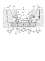
- FIG. 2 is a partial cross-sectional view around the turbine of the gas turbine according to the present embodiment.
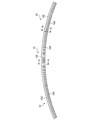
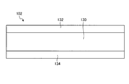
- FIG. 3 is a side view of the split ring according to the present embodiment.
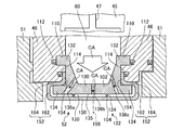
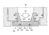
- FIG. 4 is a partially enlarged view showing the vicinity of the cross section of the split ring of the gas turbine according to the present embodiment.
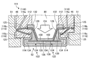
- FIG. 5 is a partially enlarged view showing the vicinity of the side surface of the split ring of the gas turbine according to the present embodiment.
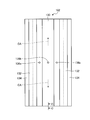
- FIG. 6 is a front view of the split ring support side member of the split ring according to the present embodiment.
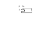
- FIG. 7 is a top view of the split ring support side member of the split ring according to the present embodiment.
- FIG. 8 is a side view of the split ring support side member of the split ring according to the present embodiment.
- FIG. 9 is a cross-sectional view of the rotation direction end of the split ring support side member of the split ring according to the present embodiment.
- FIG. 10 is a perspective view of the split ring surface side member of the split ring according to the present embodiment.
- FIG. 11 is a front view of the split ring surface side member of the split ring according to the present embodiment.
- FIG. 12 is a top view of the split ring surface side member of the split ring according to the present embodiment.
- FIG. 13 is a partially enlarged view showing the vicinity of a side surface of a split ring of a gas turbine according to another embodiment.
- FIG. 14 is a partially enlarged view showing the vicinity of a side surface of a split ring of a gas turbine according to another embodiment.
- FIG. 15 is a partially enlarged view showing the vicinity of a side surface of a split ring of a gas turbine according to another embodiment.
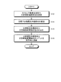
- FIG. 16 is a flowchart showing an example of a split ring manufacturing method.
- the gas turbine 1 includes a compressor 5, a combustor 6, and a turbine 7.
- a turbine shaft 8 is disposed through the center of the compressor 5, the combustor 6, and the turbine 7.
- the compressor 5, the combustor 6, and the turbine 7 are arranged in parallel along the axis CL of the turbine shaft 8 in order from the upstream side to the downstream side in the flow direction of air or combustion gas.
- Compressor 5 compresses air into compressed air.
- the compressor 5 is provided with a plurality of stages of compressor vanes 13 and a plurality of stages of compressor blades 14 in a compressor casing 12 having an air intake 11 for taking in air.
- a plurality of compressor vanes 13 at each stage are attached to the compressor casing 12 and arranged in parallel in the circumferential direction, and a plurality of compressor rotor blades 14 at each stage are attached to the turbine shaft 8 and arranged in parallel in the circumferential direction.
- the plurality of stages of compressor vanes 13 and the plurality of stages of compressor rotor blades 14 are alternately provided along the axial direction.
- the combustor 6 generates high-temperature and high-pressure combustion gas by supplying fuel to the compressed air compressed by the compressor 5.
- the combustor 6 covers, as a combustion cylinder, an inner cylinder 21 that mixes and burns compressed air and fuel, a tail cylinder 22 that guides combustion gas from the inner cylinder 21 to the turbine 7, and an outer periphery of the inner cylinder 21. 5 and an outer cylinder 23 for guiding the compressed air from 5 to the inner cylinder 21.
- the combustors 6 are arranged in the turbine casing 31 and a plurality of the combustors 6 are arranged in the circumferential direction. Note that the air compressed by the compressor 5 is temporarily stored in the vehicle compartment 24 surrounded by the turbine casing 31 and then supplied to the combustor 6.
- the turbine 7 generates rotational power by the combustion gas generated by the combustor 6.
- the turbine 7 is provided with a plurality of stages of turbine stationary blades 32 and a plurality of stages of turbine blades 33 in a turbine casing 31 serving as an outer shell.
- the turbine stationary blades 32 at each stage are attached to the turbine casing 31 and arranged in a plurality of annular shapes in the circumferential direction, and the turbine rotor blades 33 at each stage are disk-shaped discs centered on the axis CL of the turbine shaft 8. It is fixed to the outer periphery and is arranged in a plurality of rings in the circumferential direction.
- the plurality of stages of turbine stationary blades 32 and the plurality of stages of turbine rotor blades 33 are alternately provided in the axial direction.
- An exhaust chamber 34 having a diffuser portion 54 continuous with the turbine 7 is provided on the downstream side in the axial direction of the turbine casing 31 (see FIG. 1).
- the turbine shaft 8 has an end portion on the compressor 5 side supported by a bearing portion 37 and an end portion on the exhaust chamber 34 side supported by a bearing portion 38 so as to be rotatable about an axis CL.
- a drive shaft of a generator (not shown) is connected to the end of the turbine shaft 8 on the exhaust chamber 34 side.
- the turbine stationary blade 32 includes an outer shroud 51, an airfoil portion 53 extending radially inward from the outer shroud 51, and an inner shroud provided on the radially inner side of the airfoil portion 53 (see FIG. 2). (Not shown). Further, the turbine stationary blade 32 is supported from the turbine casing 31 via the heat shield ring 46 and the blade ring 45 and is on the fixed side. The plurality of stages of turbine stationary blades 32 are, in order from the upstream side in the combustion gas flow direction FG, the first turbine stationary blade 32a, the second turbine stationary blade 32b, the third turbine stationary blade 32c, and the fourth turbine stationary blade. 32d.
- the first turbine stationary blade 32a is integrally formed by an outer shroud 51a, an airfoil portion 53a, and an inner shroud (not shown).
- the second turbine stationary blade 32b is integrally formed by an outer shroud 51b, an airfoil portion 53b, and an inner shroud (not shown).
- the third turbine vane 32c is integrally formed by an outer shroud 51c, an airfoil portion 53c, and an inner shroud (not shown).
- the fourth turbine stationary blade 32d is integrally formed by an outer shroud 51d, an airfoil portion 53d, and an inner shroud (not shown).
- the plurality of stages of turbine blades 33 are arranged on the inner side in the radial direction so as to face the plurality of split rings 52.
- the turbine rotor blades 33 at each stage are provided with a predetermined gap from each divided ring 52 and are movable.
- the plurality of stages of turbine blades 33 are, in order from the upstream side in the flow direction FG of the combustion gas, the first turbine blade 33a, the second turbine blade 33b, the third turbine blade 33c, and the fourth turbine blade. 33d.
- the first turbine blade 33a is provided on the radially inner side of the first split ring 52a.
- the second turbine blade 33b, the third turbine blade 33c, and the fourth turbine blade 33d are provided on the radially inner side of the second divided ring 52b, the third divided ring 52c, and the fourth divided ring 52d. Yes.
- the plurality of stages of turbine stationary blades 32 and the plurality of stages of turbine blades 33 are arranged in order from the upstream side in the combustion gas flow direction FG, the first turbine stationary blade 32a, the first turbine rotor blade 33a, and the second turbine stationary blade 33.
- the blades 32b, the second turbine blades 33b, the third turbine blades 32c, the third turbine blades 33c, the fourth turbine blades 32d, and the fourth turbine blades 33d are arranged to face each other in the axial direction. It is provided as follows.
- the turbine casing 31 has a blade ring 45 that is disposed on the radially inner side and is supported from the turbine casing 31.
- the blade ring 45 is formed in an annular shape around the turbine shaft 8, is divided into a plurality of portions in the circumferential direction and the axial direction, and is supported from the turbine casing 31.
- the plurality of blade rings 45 are, in order from the upstream side of the combustion gas flow direction (axial direction) FG, the first blade ring 45a, the second blade ring 45b, the third blade ring 45c, and the fourth blade ring. 45d.
- a heat shield ring 46 is disposed on the radially inner side of the blade ring 45, and the turbine stationary blade 32 is supported from the blade ring 45 via the heat shield ring 46.
- the plurality of heat shield rings 46 are, in order from the upstream side of the combustion gas flow direction (axial direction) FG, the first heat shield ring 46a, the second heat shield ring 46b, the third heat shield ring 46c, and the fourth A heat shield ring 46d.
- a plurality of turbine stationary blades 32 and a plurality of split rings 52 are provided adjacent to each other in the axial direction.
- the plurality of turbine stationary blades 32 and the plurality of divided rings 52 are arranged in order from the upstream side in the flow direction FG of the combustion gas, the first turbine stationary blade 32a, the first divided ring 52a, the second turbine stationary blade 32b, and the second.
- the split ring 52b, the third turbine vane 32c, the third split ring 52c, the fourth turbine vane 32d, and the fourth split ring 52d are arranged, and are provided so as to face each other in the axial direction.
- first turbine vane 32a and the first split ring 52a are attached to the inside in the radial direction of the first blade ring 45a via the first heat shield ring 46a.
- second turbine stationary blade 32b and the second divided ring 52b are attached to the inside in the radial direction of the second blade ring 45b via the second heat shield ring 46b
- third turbine stationary blade 32c and the third divided ring 52b are attached.
- the ring 52c is attached to the inner side in the radial direction of the third blade ring 45c via the third heat shield ring 46c
- the fourth turbine stationary blade 32d and the fourth split ring 52d are connected via the fourth heat shield ring 46d. It is attached to the inner side in the radial direction of the four blade ring 45d.
- FIG. 3 is a side view of the split ring according to the present embodiment.
- FIG. 4 is a partially enlarged view showing the vicinity of the cross section of the split ring of the gas turbine according to the present embodiment.
- FIG. 5 is a partially enlarged view showing the vicinity of the side surface of the split ring of the gas turbine according to the present embodiment. 4 is a cross-sectional view taken along line AA in FIG.
- FIG. 5 is a view taken along line BB in FIG.
- FIGS. 2 to 5 show only the split ring cooling structure around the second split ring 52b, but the other split rings have the same structure.
- the second split ring 52b will be described as the split ring 52 as a representative.
- a unit including the split ring 52 and the heat shield ring 46 is also referred to as a stationary side member unit.
- a plurality of split rings 52 are arranged in series in the rotation direction (the rotation direction of the gas turbine 1, the rotation direction of the turbine shaft 8, and the rotation direction of the turbine rotor blade 33).
- the plurality of split rings 52 have a ring shape arranged in the rotation direction. That is, one divided ring 52 has an arc shape when viewed from the rotation axis direction.
- the split ring 52 is disposed between the heat shield rings 46 and supported by the heat shield rings 46.
- the cooling air supplied to the split ring 52 is supplied from a blade ring cavity 41 surrounded by the casing 24 and the blade ring 45 of the turbine 7.
- a supply opening 47 is formed in the blade ring 45.
- a cavity 80 serving as a space is provided between the heat shield ring 46, the blade ring 45, and the split ring 52.
- the cavity 80 is annularly provided over the circumferential direction.
- the cavity 80 is communicated with the blade ring cavity 41 through the supply opening 47.
- the split ring 52 is formed with a cooling flow path communicating with the cavity 80.
- the cooling air CA supplied to the blade ring cavity 41 is supplied to the cavity 80 through the supply opening 47.
- the cooling air CA of the present embodiment uses passenger compartment air on the compressor outlet side or bleed air extracted from the compressor.
- the cooling air CA supplied to the cavity 80 is supplied to the split ring 52 and passes through the cooling flow path provided in the split ring 52, thereby cooling the split ring 52.
- the heat shield ring 46 is supported by the adjacent outer shroud 51.
- the heat shield ring 46 has a recess 110 into which a part of the split ring 52 is inserted on an end face in the combustion gas flow direction, that is, a face along a direction perpendicular to the rotation axis.
- the recess 110 is formed on the surface facing the cavity 80.
- the recess 110 extends in the direction of the rotation axis of the gas turbine 1, and the end of the recess 110 in the direction of the rotation axis of the gas turbine 1 serves as a bottom surface.
- the heat shield ring 46 includes a seal mechanism (second divided ring seal mechanism) 112 and a seal mechanism (first divided ring seal mechanism) 114 that seal the contact surface with the divided ring 52. Further, the heat shield ring 46 is provided with a seal groove 116 in which a seal plate 125 for sealing between the adjacent heat shield rings 46 is disposed.
- the seal groove 116 (116a, 116b, 116c) may supply seal air for urging the seal mechanisms 112, 114 toward the split ring 52 side. In the seal groove 116, a seal plate 125 is inserted into the seal groove 116b and the seal groove 116c.
- the seal plate 125 is inserted into the two seal grooves 116 b facing each other in the adjacent heat shield ring 46 and seals between the heat shield rings 46. Further, the seal plate 125 is inserted into two seal grooves 116 c facing each other of the adjacent heat shield rings 46 to seal between the heat shield rings 46.
- the seal grooves 116b and 116c, the seal plate 125 inserted into the seal grooves 116b and 116c, and the seal mechanisms 112 and 114 in contact with the seal plate 125 serve as side seal mechanisms.
- the seal mechanisms 112 and 114, the seal groove 116, and the seal plate 125 serve as the heat shield ring seal mechanism 111.
- the seal mechanism 112 is disposed on the bottom surface of the recess 110.
- the seal mechanism 112 is in contact with the surface of the split ring 52 that is orthogonal to the rotation axis of the gas turbine 1.
- the seal mechanism 114 is disposed on a surface along a direction orthogonal to the rotation axis of the heat shield ring 46 and at a position on the radially inner side of the gas turbine 1 with respect to the seal mechanism 112.
- the seal mechanism 114 is in contact with a surface of the split ring 52 that is orthogonal to the rotation axis of the gas turbine 1.
- the seal mechanisms 112 and 114 are formed of a material having heat resistance similar to that of the heat shield ring 46 and have elasticity.
- E seals can be used for the seal mechanisms 112 and 114.
- the sealing mechanisms 112 and 114 block the flow of air in the radial direction of the gas turbine at the installed positions.
- the seal groove 116 seals between the heat shield rings 46 by inserting the seal plate 125. Further, the seal groove 116 is branched into a plurality, and the ends of the branched portions face the seal mechanisms 112 and 114, respectively.
- the seal groove 116 includes seal grooves 116a, 116b, and 116c.
- the seal groove 116a is connected to a seal air supply source that supplies seal air.
- the seal groove 116b is connected to the seal groove 116a. One end portion of the seal groove 116 b faces the outer shroud 51, and the other end portion faces the seal mechanism 112.
- a seal mechanism is disposed at one end between the seal groove 116b and the outer shroud 51.
- the seal groove 116 c has one end connected to the seal groove 116 b and the other end facing the seal mechanism 114.
- the seal groove 116 is supplied with seal air having a pressure higher than that of the air supplied to the cavity 80.
- the combustion gas is prevented from leaking from the gap between the heat shield ring 46 and other members.
- the air supplied to the seal groove 116 urges the seal mechanisms 112 and 114 toward the split ring 52. Thereby, the space between the heat shield ring 46 and the split ring 52 is sealed, and the leakage of the cooling air CA from between the heat shield ring 46 and the split ring 52 can be suppressed.
- the seal mechanisms 112 and 114 have a structure in which a part of the seal air leaks when the seal air is supplied from the seal groove 116 even when the air leaks.
- the sealing mechanisms 112 and 114 of this embodiment provided the elastic member which contacts the target object sealed in a groove shape and seals, it is not limited to this, It is good also as only a groove
- the split ring 52 has basically the same shape in the cross section in the rotation direction (surface orthogonal to the rotation direction).
- the split ring 52 includes a split ring support side member 102 and a split ring surface side member 104.
- the split ring support side member 102 is connected to the heat shield ring 46.
- the split ring support side member 102 is supported by the heat shield ring 46.
- the split ring surface side member 104 is arranged on the inner side in the radial direction of the gas turbine 1 (the radial direction of the turbine shaft 8) than the split ring support side member 102, and is supported by the split ring support side member 102.
- the split ring surface side member 104 is exposed to the flow path through which the combustion gas flows, and faces the turbine rotor blade 33.
- a cooling channel 120 is provided between the split ring support side member 102 and the split ring surface side member 104.
- FIG. 6 is a front view of the split ring support side member of the split ring according to the present embodiment.
- FIG. 7 is a top view of the split ring support side member of the split ring according to the present embodiment.
- FIG. 8 is a side view of the split ring support side member of the split ring according to the present embodiment.
- FIG. 9 is a cross-sectional view of the rotation direction end of the split ring support side member of the split ring according to the present embodiment. 9 is a cross-sectional view taken along the line CC of FIG. 6 to 9, the shape of the gas turbine 1 in the circumferential direction is shown by a straight line, but it has an arc shape as shown in FIG. 3.
- the split ring support side member (also simply referred to as “support side member”) 102 is a stationary part of the gas turbine 1 and supports the split ring surface side member 104.
- the support side member 102 is formed of a metal, for example, a heat resistant nickel alloy.
- the support side member 102 is an integrally molded component, and includes a main body 130, a first protrusion (first engagement portion) 132, and a second protrusion (second engagement portion) 134. .
- the end surface on the radially inner side of the gas turbine 1 becomes a facing portion (facing surface) 135.
- a channel resistance adjusting mechanism 122 is formed in the facing portion 135.
- the support side member 102 has through holes 136a, 136b, and 136c.
- the main body 130 is a plate-like member having a recess on the cavity 80 side, as shown in FIGS.
- the main body 130 has a shape having a recess, so that the area in contact with the cavity 80 can be increased.
- the first protrusions 132 are respectively provided at both ends of the main body 130 in the axial direction of the gas turbine 1.
- the first protrusion 132 protrudes more on the axial direction side of the gas turbine 1 than the main body 130.
- the first protrusion 132 is inserted into the recess 110 of the heat shield ring 46.
- the first protrusion 132 is in contact with the seal mechanism 112 at the end of the gas turbine 1 in the axial direction, that is, the surface farthest from the main body 130.
- the second protrusion 134 is provided on the radially inner side of the gas turbine 1 with respect to the first protrusion 132 of the main body 130.
- the second protrusions 134 are provided at both ends of the main body 130 in the axial direction of the gas turbine 1.
- the 2nd projection part 134 turns into an engaging part with which the division
- the end surface on the radially inner side of the gas turbine 1 of the second projecting portion 134 and the end surface on the radially inner side of the main body portion 130 form a facing portion 135 in the same plane.
- the through holes 136a, 136b, and 136c are passages that connect the cavity 80 and the cooling flow path 120 formed between the support side member 102 and the split ring surface side member 104.
- the through holes 136a, 136b, and 136c are formed in the order of the through hole 136a, the through hole 136b, and the through hole 136c from the upstream side to the downstream side in the combustion gas flow direction. Further, the through holes 136 a, 136 b, and 136 c of the present embodiment are formed at positions that become the center of the support side member 102 in the rotation direction of the gas turbine 1.
- the seal grooves 138 and 139 are formed on the end surface of the support side member 102 in the rotation direction of the gas turbine 1.
- the seal groove 138 extends in a direction parallel to the axial direction of the gas turbine 1, one end is formed in one second protrusion 134, and the other end is formed in the other second protrusion 134. Is done.
- the seal groove 139 has one end in contact with the seal groove 138 and the other end formed in the other first protrusion 132.
- the seal groove 139 is formed to a position where the other end is in contact with the seal mechanism 112.
- the support-side member 102 is formed with a groove connected from the seal mechanism 112 to the seal mechanism 112 by the seal grooves 138 and 139. As shown in FIG.
- the seal plate 126 is inserted into the seal groove 138.
- the seal plate 128 is inserted into the seal groove 139.
- the seal plate 126 is inserted into the seal grooves 138 and 139 of the two opposing support side members 102 to seal between the support side members 102 in the rotation direction of the gas turbine 1.
- the seal plate 128 is in contact with the seal plate 126 and seals between the seal mechanism 112 and the seal mechanism 112 and between the adjacent support side members 102.
- the seal plate 126 and the seal plate 128 serve as a support side seal mechanism.
- the split ring 52 supports the seal mechanism 112 and the heat shield ring 46 between the heat shield ring 46 by sealing the space between the support side member 102 and the heat shield ring 46 with the seal plates 126 and 128. It can be sealed with the side member 102. Thereby, in the support side member 102, the cavity 80 and the flow path of the combustion gas are separated by the seal plate 126 at the end of the gas turbine 1 in the rotation direction.
- the side seal mechanism including the seal groove 116 b and the inserted seal plate 125 is a support side member side seal mechanism that forms a seal structure connected to the support side member 102 in contact with the seal mechanism 112.
- FIG. 10 is a perspective view of the split ring surface side member of the split ring according to the present embodiment.
- FIG. 11 is a front view of the split ring surface side member of the split ring according to the present embodiment.
- FIG. 12 is a top view of the split ring surface side member of the split ring according to the present embodiment.
- the split ring surface side member (also simply referred to as “surface side member”) 104 is formed of a ceramic matrix composite material (also referred to as “CMC”).
- CMC is a material whose strength is improved by combining inorganic particles, metal particles, whiskers, short fibers, long fibers, and the like with ceramics.
- CMC is suitable for a material of a split ring because it has a lower specific gravity and higher heat resistance than, for example, a nickel-base superalloy.
- CMC is broadly classified into an oxide type (for example, Al 2 O 3 (aluminum oxide)) and a non-oxide type (for example, SiC (silicon carbide)).
- SiC fibers are added to non-oxide type SiC ceramics.
- CMC in which is combined.
- the front surface side member 104 has a surface portion 150, a folded portion 152, and a protruding portion 154.
- the surface side member 104 is connected to the surface portion 150, the folded portion 152, and the protruding portion 154, and has a shape that can be formed by bending a single plate, for example.
- the surface portion 150 is a plate-like member extending in the rotation axis direction and the radial direction of the gas turbine 1.
- the surface portion 150 is a portion that is an end surface on the radially inner side of the gas turbine 1 of the split ring 52 and is a part of the gas flow path.
- the surface 170 is a surface 170 that is a radially inner surface of the gas turbine 1 and is exposed to the combustion gas flow path R1.
- the back surface 172 which is the surface opposite to the front surface 170, faces the facing portion 135. A space between the back surface 172 and the facing portion 135 becomes the cooling flow path 120.
- returning part 152 is provided in the both ends of the rotating shaft direction of the gas turbine 1 of the surface part 150, respectively.
- the folded portion 152 includes a first portion 162 and a second portion 164.
- One end of the first portion 162 is connected to the end of the surface portion 150 in the direction of the rotation axis of the gas turbine 1, and the other end is on the radially outer side of the gas turbine 1 than the one end. is there. That is, the first portion 162 extends outward in the radial direction of the gas turbine 1 from the end portion of the surface portion 150 in the rotation axis direction of the gas turbine 1.
- the second portion 164 has one end connected to the other end of the first portion 162, and the other end is closer to the surface-side member 104 in the rotation axis direction of the gas turbine 1 than the one end.
- the second portion 164 is disposed on the radially outer side of the gas turbine 1 than the second protrusion 134 of the support side member 102.
- the second portion 164 has a radially inner surface of the gas turbine 1 facing and in contact with a radially outer surface of the second projecting portion 134 of the gas turbine 1.
- the surface side member 104 is engaged with the second protrusion 134 of the support side member 102 at the surface portion 150 and the folded portion 152.
- the second portion 164 is in contact with the second protrusion 134
- the first portion 162 is not in contact with the first protrusion 132.
- the protruding portion 154 extends from the folded portion 152 to the outside in the radial direction of the gas turbine 1.
- the surface on the side of the center line 159 of the surface side member 104 in the rotation axis direction of the gas turbine 1 faces the support side member 102.
- the protrusion 154 faces the heat shield ring 46 at a surface on the end side of the surface side member 104 in the rotation axis direction of the gas turbine 1.
- the protrusion 154 is in contact with the seal mechanism 114 at the surface facing the heat shield ring 46. Thereby, the space between the protruding portion 154 and the heat shield ring 46 is sealed by the seal mechanism 114.
- the side seal mechanism including the seal groove 116 c and the inserted seal plate 125 is a side seal mechanism for the surface side member that forms a seal structure connected to the surface side member 104 in contact with the seal mechanism 114.
- the flow path resistance adjusting mechanism 122 is provided in the cooling flow path 120.
- the flow path resistance adjustment mechanism 122 adjusts the flow path resistance of the cooling flow path 120 and the ease of air flow, and the pressure of the cooling air in the cooling flow path 120 on the upstream side of the combustion gas flow of the gas turbine 1 is adjusted to the downstream side.
- the pressure is higher than the pressure of the cooling air in the cooling channel 120.
- the flow path resistance adjusting mechanism 122 includes two partition plates 124 and through holes 136a, 136b, and 136c.
- the partition plate 124 protrudes in a direction away from the facing portion 135, and the tip is in contact with the surface side member 104.
- One partition plate 124 is disposed between the through hole 136a and the through hole 136b, and the other partition plate 124 is disposed between the through hole 136b and the through hole 136c.
- the partition plate 124 extends from one end of the split ring 52 to the other end in the rotation direction of the gas turbine 1.
- the through holes 136a, 136b, and 136c have smaller diameters in the order of the through hole 136a, the through hole 136b, and the through hole 136c. That is, the through hole 136a has a larger diameter than the through hole 136b.
- the through hole 136b has a larger diameter than the through hole 136c.
- the diameter of the through-hole becomes smaller as it goes from upstream to downstream of the combustion gas flow.
- the flow path resistance adjusting mechanism 122 can set the flow path resistances of the three spaces of the cooling flow path 120 partitioned by the partition plate 124 to different resistances.
- the flow resistance of the gas turbine 1 on the upstream side of the combustion gas flow is smaller than that on the downstream side, so that the pressure loss is reduced and cooling air with higher pressure is supplied.
- the split ring cooling method will be described by explaining the flow path of the cooling air CA flowing through the split ring 52.
- the cooling air CA supplied to the cavity 80 passes through the through holes 136 a, 136 b, 136 c and is supplied to each of the cooling flow paths 120 partitioned by the partition plate 124. That is, the cooling air CA passes through the split ring support side member 102 and flows into the cooling flow path between the split ring support side member 102 and the split ring surface side member 104.
- the cooling air CA that has passed through the through holes 136a, 136b, and 136c flows in the cooling flow path 120 from the center in the rotation direction of the gas turbine 1 toward the end.
- the cooling air CA flows through the cooling flow path 120 in both directions along the rotation direction of the gas turbine 1, that is, in two directions away from the through holes 136a, 136b, and 136c in the rotation direction.
- the cooling air CA that has flowed into the cooling flow path 120 also flows into the cooling space between the axial side surface of the split ring support side member 102 and the first portion (side surface member) 162 of the split ring surface side member 104.
- the axially facing side surface of the split ring support side member 102 and the first portion 162 that is, the part facing the axial direction in the cooling channel 120 among the split ring support side member and the split ring surface side member. Can be cooled.
- the cooling air CA that has moved to the end of the split ring 52 in the rotation direction of the gas turbine 1 is discharged from the gap of the split ring 52 to the combustion gas flow path R1. That is, the cooling air CA that has moved to the end of the split ring 52 in the rotation direction of the gas turbine 1 is between the split ring surface side member 104 and the split ring surface side member 104 that is adjacent in the rotation direction. To be discharged. Further, the cooling air CA that has moved to the end of the split ring 52 in the rotational direction of the gas turbine 1 also flows between the split ring support side member 102 and the adjacent split ring support member 102, and Cool the sides in the direction of rotation. The split ring 52 is thus cooled by the flow of the cooling air CA.
- the split ring 52 is configured such that the split ring surface side member 104 formed of CMC is arranged on the inner side in the radial direction of the gas turbine 1 of the split ring support side member 102 formed of metal.
- the member 104 has a shape that forms the combustion gas passage R1, the heat resistance of the split ring 52 can be increased.
- the split ring 52 is provided with a seal groove 138 and a seal plate 126 on the radially inner side of the end portion of the folded portion 152 on the radially outer side of the gas turbine 1, thereby shortening the distance between the cavity 80 and the cooling flow path 120. be able to. Thereby, the division
- the split ring 52 is provided with a protruding portion 154 on the split ring surface side member 104, and a sealing mechanism 114 is provided between the protruding portion 154 and the heat shield ring 46, and sealing is performed, so that the sealing mechanism has a ring shape. It is possible to improve the sealing performance while simplifying the installation. Since the sealing property can be enhanced, air leakage can be suppressed and each air can be used efficiently. Specifically, the amount of air leaking into the combustion gas flow path can be reduced while appropriately cooling the split ring 52. Thereby, the quantity of the compressed air used for cooling air can be reduced, and the quantity of the leakage air which lowers the temperature of combustion gas can also be reduced, and the efficiency of the gas turbine 1 can be improved.
- the split ring 52 has a cooling passage between the back surface 172 and the facing portion 135, the second portion 164 of the folded portion 152 is in contact with the second protruding portion 134, and the first portion 162 is not in contact with the first protruding portion 132.
- the part which contacts the surface side member 104 of the support side member 102 can be made into the position far from a combustion gas flow path. Thereby, the temperature around the part where the support side member 102 and the surface side member 104 contact can be lowered, and the temperature rise of the support side member 102 can be suppressed. Moreover, it can suppress that the support side member 102 and the surface side member 104 contact in the position where temperature is high.
- the split ring 52 is provided with a flow path resistance adjusting mechanism 122, and by adjusting the pressure balance of the cooling air flowing through the cooling flow path 120, the cooling air CA can be efficiently flowed, and the amount of the cooling air CA can be reduced. Can be reduced.
- the split ring 52 is a flow path resistance adjusting mechanism 122 that converts the pressure of the cooling air flowing through the cooling flow path 120 on the upstream side in the combustion gas flow direction of the gas turbine 1 to the cooling space on the downstream side in the combustion gas flow direction. By making it higher than the pressure of the cooling air flowing through the cooling air CA, it is possible to efficiently flow the cooling air CA.
- the split ring 52 is provided with a partition plate (partition part) 124 as the flow path resistance adjusting mechanism 122, and the cooling flow path 120 is separated into a plurality of spaces in a cross section orthogonal to the rotation direction, whereby the flow direction of the combustion gas ,
- the cooling flow path 120 can be separated, and the pressure of the cooling air can be easily changed depending on the position in the flow direction of the combustion gas.
- the split ring 52 can simplify the structure of the split ring surface side member 104 by providing the partition plate 124 on the split ring support side member 102. Further, the split ring 52 can be manufactured easily by forming the split ring surface side member 104 in a shape that allows the cross section to be drawn with one stroke as in the present embodiment, that is, by bending a single plate. .
- the split ring 52 is provided with through holes 136a, 136b, and 136c only in the vicinity of the center in the rotation direction of the gas turbine 1, and the split ring 52 is split by flowing the air flowing through the cooling flow path 120 along the rotation direction of the gas turbine 1.
- the ring support side member 102 and the split ring surface side member 104 can be cooled with an appropriate balance. Specifically, by using face-to-face cooling in which the air flowing through the cooling flow path 120 flows along the rotation direction of the gas turbine 1, it is possible to divide the cooling amount of the divided ring support side member 102 compared to the case of impingement cooling. The cooling amount of the ring surface side member 104 can be reduced. Thereby, the split ring 52 can suppress the excessive cooling of the split ring surface side member 104 formed of CMC and having high heat resistance while sufficiently cooling the split ring support side member 102 made of metal. .
- the split ring 52 has through-holes 136a, 136b, and 136c formed at the center of the support-side member 102 in the rotation direction of the gas turbine 1, and the center in the rotation direction of the gas turbine 1.
- the cooling air supplied to the cooling flow path 120 with the split ring surface side member 104 is changed in the rotational direction of the gas turbine 1. It can flow efficiently from the center to the end, and convection cooling can be performed efficiently.
- the center region is a region of (1/4) L from the center, and the end region is from the end. This is an area of (1/4) L.
- FIG. 13 is a partially enlarged view showing the vicinity of a side surface of a split ring of a gas turbine according to another embodiment.
- the split ring 52a shown in FIG. 13 is the same as the split ring 52 except for some shapes.
- the different points of the structure of the split ring will be described with emphasis, and parts having the same structure will be given the same reference numerals and description thereof will be omitted.
- the flow path resistance adjusting mechanism 122a is formed of a member different from the split ring support side member 102a and the split ring surface side member 104a.
- the flow path resistance adjusting mechanism 122 a includes a partition plate 180 and a buffer material 186.
- the split ring support side member 102a has a recess 182 at a position where the partition plate 180 is disposed.
- the recess 182 extends in the rotation direction of the gas turbine 1.
- the partition plate 180 is a plate that separates the cooling flow path 120 into a plurality of spaces, like the partition plate 124 of the flow path resistance adjusting mechanism 122.
- the partition plate 180 does not need to completely separate the space, and air may flow as long as the pressure difference can be maintained.
- the partition plate 180 is inserted into the recess 182 and protrudes toward the split ring surface side member 104a.
- the buffer material 186 is disposed between the partition plate 180 and the split ring surface side member 104a.
- the buffer material 186 is made of a material having heat resistance and a low reactivity with the CMC forming the split ring surface side member 104a, for example, a material other than metal.
- As the buffer material 186 for example, SiC felt can be used.
- the flow path resistance adjusting mechanism 122a may be a member different from the split ring support side member 102a and the split ring surface side member 104a. Thereby, manufacture of each member can be simplified.
- the split ring 52a is provided with a buffer material 186 made of a material having low reactivity with CMC as a reaction preventing layer between the partition plate 180 and the split ring surface side member 104a.
- the durability of the surface side member 104a can be increased.
- the surface portion 150 of the split ring surface side member 104a is in a high temperature because it contacts the combustion gas flow path.
- the surface part 150 which became high temperature is a metal which reacts when it contacts.
- the buffer material 186 it is possible to suppress reaction with other members even when the surface portion 150 becomes high temperature, and durability can be increased.
- the partition plate 180 may be formed of a material having heat resistance and low reactivity with the CMC forming the split ring surface side member 104a. . That is, the same effect can be obtained by forming the member in contact with the back surface 182 of the split ring surface side member 104a that is in contact with the CMC at a high temperature from a material having low reactivity with the CMC. Further, it is preferable to provide a cushioning material between the partition plate 124 of the split ring 52 and the surface portion 150. In this manner, the part of the partition plate (partition part) that contacts the surface opposite to the surface part of the split ring surface side member is made of a material other than metal, thereby protecting the split ring surface side member. , Durability can be increased.
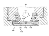
- FIG. 14 is a partially enlarged view showing the vicinity of a side surface of a split ring of a gas turbine according to another embodiment.
- the split ring 52b shown in FIG. 14 is the same as the split ring 52 except for some shapes.
- different points of the structure of the split ring 52b will be described with emphasis, and portions having the same structure will be denoted by the same reference numerals and description thereof will be omitted.
- the split ring 52b has a split ring support side member 102b and a split ring surface side member 104b.
- the split ring 52b includes a facing portion 135b in the flow path resistance adjusting mechanism 122b.
- the split ring 52b includes a structure in which the radial position of the gas turbine of the split ring support facing portion is different.
- the facing portion 135b of the split ring support side member 102b is inclined with respect to the back surface 172 of the split ring surface side member 104b.
- the facing portion 135b is inclined so as to approach the back surface 172 of the split ring surface side member 104b as it goes from upstream to downstream in the combustion gas flow direction.
- the split ring 52b is configured such that the flow path resistance adjusting mechanism 122b has a shape that approaches the back surface 172 of the split ring surface side member 104b as the facing portion 135b moves from upstream to downstream in the combustion gas flow direction. It can be set as the structure where a cooling flow path becomes narrow as it goes to the downstream from the upstream of a direction. Thereby, the flow path resistance adjusting mechanism 122b can increase the flow path resistance from the upstream in the combustion gas flow direction toward the downstream, and the pressure of the cooling air on the upstream side is made higher than the pressure of the cooling air on the downstream side. Can also be high.
- the flow path resistance adjusting mechanism 122b changes the inclination of the facing portion 135b, but may have a structure with different flow path resistances, and may change the surface roughness of the facing portion 135b. May be provided. Further, the flow path resistance adjusting mechanism 122b may change the flow path resistance in the direction of the rotation axis of the gas turbine 1. That is, the flow path resistance adjusting mechanism 122b may have a shape in which the height of the cooling flow path 120 decreases as it goes from the center in the rotation axis direction of the gas turbine 1 to the end. Further, the flow path resistance adjusting mechanism 122b may further include a partition plate. Further, in the flow path resistance adjusting mechanism 122b, the partition plate may have a shape whose width changes in the rotation axis direction of the gas turbine 1.
- the channel resistance adjusting mechanisms 122, 122a, 122b of the split rings 52, 52a, 52b disclosed in the present specification can be used singly or in combination.
- the split rings 52, 52a, 52b can increase the flow path resistance from the upstream to the downstream in the combustion gas flow direction by combining a plurality of flow resistance adjustment mechanisms 122, 122a, 122b. And the pressure of the cooling air on the upstream side can be made higher than the pressure of the cooling air on the downstream side.
- FIG. 15 is a partially enlarged view showing the vicinity of a side surface of a split ring of a gas turbine according to another embodiment.
- the split ring 52c shown in FIG. 15 is the same as the split ring 52 except for some shapes.
- different points of the structure of the split ring 52c will be described with emphasis, and portions having the same structure will be denoted by the same reference numerals and description thereof will be omitted.
- the split ring 52c has a split ring support side member 102c and a split ring surface side member 104c.
- the split ring surface side member 104c has the same structure as that of the split ring surface side member 104 except that the projecting portion 154 is not provided.
- the split ring support side member 102 c is in contact with the seal mechanism 114.
- the split ring 52c has a structure that does not include the projecting portion 154, so that the sealing performance is lowered. However, by adjusting the pressure by the flow path resistance adjusting mechanism 122, the seal air can be used efficiently.
- FIG. 16 is a flowchart illustrating an example of a method of manufacturing a split ring.
- the split ring surface side member 104 is manufactured with a ceramic matrix composite material (step S12). Further, the split ring surface side member 104 can be manufactured by a method of manufacturing a part manufactured from a ceramic matrix composite material.
- the split ring support side member 102 is manufactured with a metal (step S14). The split ring support side member 102 can be manufactured by performing machining such as casting, cutting, and polishing. Step S12 and step S14 may be executed in reverse order or in parallel. A plurality of split ring surface side members 104 and split ring surface side members 102 may be manufactured simultaneously.
- the split ring surface side member is fitted into the split ring support side member (step S16). Specifically, in the radial direction of the gas turbine 1, the second portion (projection) 164 of the split ring surface side member 104 is more radial than the second projection (projection) 134 of the split ring support side portion 102.
- the split ring surface side member 104 is fitted into the split ring support side member 102 at a position on the outer side, and a cooling channel 120 is formed between the split ring surface side member 104 and the split ring support side member 102.
- split ring support side member 102 and the split ring surface side member 104 move relative to the split ring support side member 102 and the split ring surface side member 104 in the extending direction (the direction along the rotation direction of the gas turbine at the time of installation). By doing so, the split ring surface side member 104 can be fitted into the split ring support side member 102.
- the split ring which is a unit of the split ring support side member 102 and the split ring surface side member 104 is connected in the circumferential direction (step S18).
- a ring shape is formed, and part of the outer peripheral surface of the flow path through which the combustion gas passes.
- a seal plate 126 is disposed between the adjacent split rings 52.
- the split ring support side member 102 is installed on the heat shield ring 46. After that, the split ring support side member 102 and the split ring surface side member 104 may be fitted together.
- the split ring 52 is a combination of the split ring support side member 102 and the split ring surface side member 104, and the second portion (projection) 164 of the split ring surface side member 104 is the split ring support side. It is easy to assemble the split ring surface side member 104 by fitting it into the split ring support side member 102 at a position that is more radially outward than the second protrusion (projection) 134 of the part 102. Can be manufactured.
Abstract
In order to enhance the efficiency of a gas turbine, this split ring surface-side member is included in a split ring, disposed at a position on the stationary side of the gas turbine and facing a moving blade, and forms a portion of a combustion gas flow path through which a combustion gas flows. The split ring surface-side member has: a surface part which is formed of a ceramic-based composite material and forms the combustion gas flow path; a folded part provided with a first section connected to the surface part and extending outward in a radial direction of the gas turbine, and a second section extending from an end portion of the first section toward the center line side of the surface part; and a protruding part extending outward from the folded part in a radial direction of the gas turbine.
Description
本発明は、燃焼ガスによって回転するガスタービンに関するものである。
The present invention relates to a gas turbine that is rotated by combustion gas.
従来、回転軸と、回転軸に対して径方向外側に延びるタービン動翼と、タービン動翼から径方向外側に離間して設けられた分割環と、分割環の軸方向に隣接するタービン静翼と、を備えたガスタービンが知られている。
Conventionally, a rotating shaft, a turbine blade extending radially outward with respect to the rotating shaft, a split ring provided to be spaced radially outward from the turbine blade, and a turbine stator blade adjacent in the axial direction of the split ring Are known.
特許文献1には、燃焼ガスが流れる経路と対面する側に配置され、セラミックス基複合材料で形成された表面側部材と、表面側部材よりもガスタービンの径方向外側に配置され、表面側部材を支持し、遮熱環に支持され、金属で形成された支持側部材と、を有する分割環が記載されている。
In Patent Document 1, a surface-side member that is disposed on the side facing the path through which the combustion gas flows and is formed of a ceramic matrix composite material is disposed on the radially outer side of the gas turbine with respect to the surface-side member. And a support-side member that is supported by a heat shield ring and formed of metal is described.
特許文献1に示すように、燃焼ガスが流れる面にセラミックス基複合材料で形成された部材を配置することで、金属で形成された部材を配置した場合よりも耐久性を高くすることができる。しかしながら、特許文献1に記載の構造では、冷却空気の供給の効率の向上に限界がある。また、特許文献1に記載の構造では、各部のシール性能の向上に限界がある。このため、冷却空気の効率及びシール性能の少なくとも一方に基づいて、ガスタービンの効率の向上に限界がある。
As shown in Patent Document 1, by disposing a member formed of a ceramic matrix composite material on the surface through which combustion gas flows, durability can be made higher than when a member formed of metal is disposed. However, the structure described in Patent Document 1 has a limit in improving the efficiency of supplying cooling air. Further, the structure described in Patent Document 1 has a limit in improving the sealing performance of each part. For this reason, there is a limit in improving the efficiency of the gas turbine based on at least one of the efficiency of the cooling air and the sealing performance.
そこで、本発明は、ガスタービンの効率をより高くすることができる分割環表面側部材、分割環支持側部材、分割環、静止側部材ユニット、これを有するガスタービン、分割環冷却方法及び分割環製造方法を提供することを課題とする。
Therefore, the present invention provides a split ring surface side member, a split ring support side member, a split ring, a stationary side member unit, a gas turbine having the same, a split ring cooling method, and a split ring that can further increase the efficiency of the gas turbine. It is an object to provide a manufacturing method.
上記課題を解決するために本発明は、ガスタービンの静止側であり、動翼と対面する位置に配置される分割環に含まれ、燃焼ガスが流れる燃焼ガス流路の一部である分割環表面側部材であって、セラミックス基複合材料で形成され、前記燃焼ガス流路を形成する表面部と、前記表面部と連結し、前記ガスタービンの径方向外側に伸びた第1部分及び前記第1部分の端部から前記表面部の中心線側に伸びた第2部分を備える折り返し部と、前記折り返し部から、前記ガスタービンの径方向外側に伸びた突出部と、を有することを特徴とする。
In order to solve the above-described problems, the present invention provides a split ring that is included in a split ring disposed on a stationary side of a gas turbine and facing a moving blade, and is a part of a combustion gas flow path through which combustion gas flows. A surface-side member formed of a ceramic matrix composite material, the surface portion forming the combustion gas flow path, connected to the surface portion and extending radially outward of the gas turbine; and the first portion A folded portion having a second portion extending from the end portion of one portion toward the center line side of the surface portion; and a projecting portion extending from the folded portion to the radially outer side of the gas turbine. To do.
上記課題を解決するために本発明は、ガスタービンの静止側であり、動翼と対面する位置に配置される分割環に含まれ、燃焼ガスが流れる燃焼ガス流路の一部であり、分割環表面側部材を支持する分割環支持側部材であって、金属で形成され、前記分割環表面側部材が係合する係合部と、前記分割環表面側部材の前記燃焼ガス流路を形成する表面部とは反対側の面と対面し、前記表面部との冷却空気が流れる冷却空間を形成する対向部と、を有し、前記対向部は、前記冷却空間の流路抵抗を調整する流路抵抗調整機構を備えることを特徴とする。
In order to solve the above-mentioned problems, the present invention is a stationary side of a gas turbine, is included in a split ring arranged at a position facing a moving blade, and is a part of a combustion gas flow path through which combustion gas flows. A split ring support side member for supporting the ring surface side member, which is formed of metal and forms an engagement portion with which the split ring surface side member is engaged, and the combustion gas flow path of the split ring surface side member And a facing portion that forms a cooling space through which cooling air flows with the surface portion. The facing portion adjusts the flow resistance of the cooling space. A flow path resistance adjusting mechanism is provided.
また、前記対向部と前記冷却空気を供給する冷却空気供給空間とを接続し、前記冷却空気が流れる貫通孔を複数有し、前記貫通孔は、前記ガスタービンの燃焼ガス流れ方向の位置で大きさが異なることが好ましい。
Further, the opposed portion is connected to a cooling air supply space for supplying the cooling air, and has a plurality of through holes through which the cooling air flows, and the through holes are large at positions in the combustion gas flow direction of the gas turbine. Are preferably different.
また、前記流路抵抗調整機構は、前記ガスタービンの燃焼ガス流れ方向の位置で、前記対向部と前記分割環表面側部材との距離が異なる構造を含むことが好ましい。
Further, it is preferable that the flow path resistance adjusting mechanism includes a structure in which a distance between the facing portion and the split ring surface side member is different at a position in the combustion gas flow direction of the gas turbine.
また、前記流路抵抗調整機構は、前記対向部を含み、前記対向部は、位置に応じて表面粗さが異なることが好ましい。また、前記流路抵抗調整機構は、前記対向部を含み、前記対向部は、凹凸部が形成されていることが好ましい。
Moreover, it is preferable that the flow path resistance adjusting mechanism includes the facing portion, and the facing portion has a different surface roughness depending on the position. Moreover, it is preferable that the said flow-path resistance adjustment mechanism contains the said opposing part, and the uneven | corrugated | grooved part is formed in the said opposing part.
また、前記流路抵抗調整機構は、前記ガスタービンの燃焼ガス流れ方向の上流側の前記冷却空間を流れる冷却空気の圧力を、燃焼ガス流れ方向の下流側の前記冷却空間を流れる冷却空気の圧力よりも高くすることが好ましい。
Further, the flow path resistance adjusting mechanism is configured such that the pressure of the cooling air flowing in the cooling space upstream in the combustion gas flow direction of the gas turbine is the pressure of the cooling air flowing in the cooling space downstream in the combustion gas flow direction. Higher than that.
また、前記流路抵抗調整機構は、前記冷却空間を回転方向に直交する断面において複数の空間に分離する仕切部を含むことが好ましい。
Moreover, it is preferable that the flow path resistance adjusting mechanism includes a partition portion that separates the cooling space into a plurality of spaces in a cross section orthogonal to the rotation direction.
また、前記仕切部は、前記対向部に一体で設けられていることが好ましい。
Moreover, it is preferable that the partition portion is provided integrally with the facing portion.
また、前記仕切部は、板状部材であり、対面する位置に形成された溝に挿入されていることが好ましい。
Further, it is preferable that the partition portion is a plate-like member and is inserted into a groove formed at a facing position.
また、前記仕切部は、前記分割環表面側部材の前記表面部とは反対側の面と接する部分が、金属以外の材料であることが好ましい。
Further, it is preferable that the partitioning portion is made of a material other than metal at a portion in contact with the surface opposite to the surface portion of the split ring surface side member.
また、前記仕切部は、前記分割環表面側部材の前記表面部とは反対側の面と接する部分に反応防止材が配置されていることが好ましい。
In addition, it is preferable that a reaction preventing material is disposed in a portion of the partition portion that is in contact with the surface of the split ring surface side member opposite to the surface portion.
上記課題を解決するために本発明は、ガスタービンの静止側であり、動翼と対面する位置に配置される分割環に含まれ、円弧形状であり、分割環支持側部材であって、前記円弧形状の軸方向に突出した第1係合部と、前記円弧形状の中心点側に形成され、前記軸方向に突出した第2係合部と、前記円弧形状の中心線側に沿って形成された貫通孔と、前記円弧形状の中心線側の面に形成され、前記中心線側に突出し、前記円弧形状の円弧の方向に沿って延在する凸部と、を有することを特徴とする。
In order to solve the above problems, the present invention is a stationary ring of a gas turbine, is included in a split ring disposed at a position facing a moving blade, has an arc shape, and is a split ring support side member, A first engagement portion projecting in the axial direction of the arc shape, a second engagement portion projecting in the axial direction, formed along the center point side of the arc shape, and formed along the center line side of the arc shape And a convex portion that is formed on the surface of the arc-shaped center line side, protrudes toward the center line side, and extends along the direction of the arc of the arc shape. .
上記課題を解決するために本発明は、ガスタービンの静止側であり、動翼と対面する位置に配置される分割環であって、燃焼ガスが流れる燃焼ガス流路の一部であり、セラミックス基複合材料で形成された分割環表面側部材と、前記分割環表面側部材よりも前記ガスタービンの径方向外側に配置され、前記分割環表面側部材を支持し、前記分割環表面側部材との間に冷却空気が流れる冷却空間を形成し、金属で形成された分割環支持側部材と、前記分割環表面側部材の前記表面部とは反対側の面と対面する前記分割環支持側部材の裏面との間に配置され、前記冷却空間の流路抵抗を調整する流路抵抗調整機構と、を有することを特徴とする。
In order to solve the above-described problems, the present invention is a split ring disposed on a stationary side of a gas turbine and facing a moving blade, and is a part of a combustion gas flow path through which combustion gas flows. A split ring surface side member formed of a base composite material, and arranged on a radially outer side of the gas turbine than the split ring surface side member, supporting the split ring surface side member, and the split ring surface side member; A split ring support side member that forms a cooling space through which cooling air flows, and faces the surface of the split ring surface side member opposite to the surface portion of the split ring surface side member. And a flow path resistance adjusting mechanism that adjusts the flow path resistance of the cooling space.
また、前記流路抵抗調整機構は、前記ガスタービンの燃焼ガス流れ方向の上流側の前記冷却空間を流れる冷却空気の圧力を、燃焼ガス流れ方向の下流側の前記冷却空間を流れる冷却空気の圧力よりも高くすることが好ましい。
Further, the flow path resistance adjusting mechanism is configured such that the pressure of the cooling air flowing in the cooling space upstream in the combustion gas flow direction of the gas turbine is the pressure of the cooling air flowing in the cooling space downstream in the combustion gas flow direction. Higher than that.
また、前記流路抵抗調整機構は、前記冷却空間を回転方向に直交する断面において複数の空間に分離する仕切部を含み、前記仕切部は、前記分割環表面側部材に一体で設けられていることが好ましい。
Further, the flow path resistance adjusting mechanism includes a partition part that separates the cooling space into a plurality of spaces in a cross section orthogonal to the rotation direction, and the partition part is provided integrally with the divided ring surface side member. It is preferable.
また、前記仕切部は、前記分割環支持側部材に一体で設けられていることが好ましい。
Further, it is preferable that the partition portion is provided integrally with the split ring support side member.
また、前記仕切部は、板状部材であり、対面する位置に形成された溝に挿入されていることが好ましい。
Further, it is preferable that the partition portion is a plate-like member and is inserted into a groove formed at a facing position.
また、前記仕切部は、前記分割環表面側部材の前記表面部とは反対側の面と接する部分が、金属以外の材料であることが好ましい。
Further, it is preferable that the partitioning portion is made of a material other than metal at a portion in contact with the surface opposite to the surface portion of the split ring surface side member.
また、前記仕切部は、前記分割環表面側部材の前記表面部とは反対側の面と接する部分に反応防止材が配置されていることが好ましい。
In addition, it is preferable that a reaction preventing material is disposed in a portion of the partition portion that is in contact with the surface of the split ring surface side member opposite to the surface portion.
上記課題を解決するために本発明は、ガスタービンの静止側であり、動翼と対面する位置に配置される分割環に含まれ、燃焼ガスが流れる燃焼ガス流路の一部であり、分割環表面側部材を支持する分割環支持側部材であって、金属で形成され、前記分割環表面側部材が係合する係合部と、前記分割環表面側部材の前記燃焼ガス流路を形成する表面部とは反対側の面と対面し、前記表面部との冷却空気が流れる冷却空間を形成する対向部と、前記対向部と前記冷却空気を供給する冷却空気供給空間とを接続し、前記冷却空気が流れる複数の貫通孔と、を有し、前記ガスタービンの回転方向において、中心領域の貫通孔の合計面積が、端部領域の貫通孔の合計面積よりも大きいことを特徴とする。
In order to solve the above-mentioned problems, the present invention is a stationary side of a gas turbine, is included in a split ring arranged at a position facing a moving blade, and is a part of a combustion gas flow path through which combustion gas flows. A split ring support side member for supporting the ring surface side member, which is formed of metal and forms an engagement portion with which the split ring surface side member is engaged, and the combustion gas flow path of the split ring surface side member Facing the surface opposite to the surface portion to be connected, forming a cooling space through which cooling air flows with the surface portion, and connecting the facing portion and the cooling air supply space for supplying the cooling air, A plurality of through holes through which the cooling air flows, and a total area of the through holes in the central region is larger than a total area of the through holes in the end region in the rotation direction of the gas turbine. .
上記課題を解決するために本発明は、ガスタービンの静止側であり、動翼と対面する位置に配置される分割環に含まれ、燃焼ガスが流れる燃焼ガス流路の一部であり、分割環表面側部材を支持する分割環支持側部材であって、金属で形成され、前記分割環表面側部材が係合する係合部と、前記分割環表面側部材の前記燃焼ガス流路を形成する表面部とは反対側の面と対面し、前記表面部との冷却空気が流れる冷却空間を形成する対向部と、ガスタービン回転方向に隣接する面に配置され、前記係合部の前記ガスタービンの径方向外側の端部よりも径方向内側に配置されたシール構造と、を有することを特徴とする。
In order to solve the above-mentioned problems, the present invention is a stationary side of a gas turbine, is included in a split ring arranged at a position facing a moving blade, and is a part of a combustion gas flow path through which combustion gas flows. A split ring support side member for supporting the ring surface side member, which is formed of metal and forms an engagement portion with which the split ring surface side member is engaged, and the combustion gas flow path of the split ring surface side member Facing the surface on the opposite side of the surface portion to be formed, facing the surface portion forming a cooling space through which cooling air flows, and a surface adjacent to the gas turbine rotation direction, and the gas of the engagement portion And a seal structure disposed radially inward of an end portion on the radially outer side of the turbine.
また、前記シール構造は、シール溝し、前記シール溝に挿入されたシール板し、前記シール板は前記分割環表面側部材と異なる材料であることが好ましい。また、前記シール板は、金属であることが好ましい。
Also, the seal structure is preferably a seal groove, a seal plate inserted into the seal groove, and the seal plate is preferably made of a material different from that of the split ring surface side member. The seal plate is preferably a metal.
また、前記シール構造は、周方向に隣接する他の分割環支持側部材との間をシールすることが好ましい。
In addition, it is preferable that the seal structure seals between other ring-ring support side members adjacent in the circumferential direction.
また、前記シール構造よりも径方向外側に配置され、前記ガスタービンの軸方向に隣接する他の部材との間をシールする外側シール機構をさらに有することが好ましい。
Further, it is preferable to further include an outer seal mechanism that is disposed radially outside the seal structure and seals between other members adjacent in the axial direction of the gas turbine.
上記課題を解決するために本発明は、ガスタービンの静止側であり、動翼と対面する位置に配置される分割環であって、燃焼ガスが流れる燃焼ガス流路の一部であり、セラミックス基複合材料で形成された分割環表面側部材と、前記分割環表面側部材よりも前記ガスタービンの径方向外側に配置され、前記分割環表面側部材を支持し、前記分割環表面側部材との間に冷却空気が流れる冷却空間を形成し、金属で形成された分割環支持側部材と、を有し、前記分割環表面側部材は、前記燃焼ガス流路を形成する表面部と、前記表面部と連結し、前記分割環支持側部材に係止する折り返し部と、を有し、前記分割環支持側部材は、ガスタービン回転方向に隣接する面に配置され、前記折り返し部の前記ガスタービンの径方向外側の端部よりも径方向内側に配置されたシール構造を有することを特徴とする。
In order to solve the above-described problems, the present invention is a split ring disposed on a stationary side of a gas turbine and facing a moving blade, and is a part of a combustion gas flow path through which combustion gas flows. A split ring surface side member formed of a base composite material, and arranged on a radially outer side of the gas turbine than the split ring surface side member, supporting the split ring surface side member, and the split ring surface side member; Forming a cooling space through which cooling air flows, and a split ring support side member made of metal, and the split ring surface side member includes a surface portion that forms the combustion gas flow path, and A folded portion connected to the surface portion and engaged with the split ring support side member, and the split ring support side member is disposed on a surface adjacent to the gas turbine rotating direction, and the gas of the folded portion The diameter is larger than the radially outer end of the turbine And having the placed sealing structure countercurrent inside.
また、前記シール構造は、シール溝を有し、前記シール溝に挿入されたシール板を有し、前記シール板は前記分割環表面側部材と異なる材料であることが好ましい。また、前記シール板は、金属であることが好ましい。
Further, it is preferable that the seal structure has a seal groove and has a seal plate inserted into the seal groove, and the seal plate is made of a material different from that of the split ring surface side member. The seal plate is preferably a metal.
上記課題を解決するために本発明は、上記に記載の分割環表面側部材と、前記分割環表面側部材よりも前記ガスタービンの径方向外側に配置され、前記分割環表面側部材を支持し、前記分割環表面側部材との間に冷却空気が流れる冷却空間を形成し、金属で形成された分割環支持側部材と、を有し、前記分割環表面側部材は、前記燃焼ガス流れの上流側の前記突出部の前記燃焼ガス流れの上流側及び前記燃焼ガス流れの下流側の前記突出部の前記燃焼ガス流れの下流側の少なくとも一方にシール機構を有することを特徴とする。
In order to solve the above problems, the present invention provides a split ring surface side member as described above, and is arranged radially outside the gas turbine with respect to the split ring surface side member, and supports the split ring surface side member. A cooling space through which cooling air flows is formed between the split ring surface side member and a split ring support side member formed of metal, and the split ring surface side member of the combustion gas flow A seal mechanism is provided on at least one of the upstream side of the combustion gas flow of the upstream projecting portion and the downstream side of the combustion gas flow of the projecting portion on the downstream side of the combustion gas flow.
上記課題を解決するために本発明は、ガスタービンの静止側であり、動翼と対面する位置に配置される分割環であって、燃焼ガスが流れる燃焼ガス流路の一部であり、セラミックス基複合材料で形成された分割環表面側部材と、前記分割環表面側部材よりも前記ガスタービンの径方向外側に配置され、前記分割環表面側部材を支持し、前記分割環表面側部材との間に冷却空気が流れる冷却空間を形成し、金属で形成された分割環支持側部材と、を有し、前記分割環支持側部材は、前記ガスタービンの軸方向に延在し、両端が前記軸方向に隣接する部材と接し、前記ガスタービンの径方向の空気の流れをシールするシール機構を有し、前記分割環表面側部材は、前記シール機構よりも前記ガスタービンの径方向の内側に配置されることを特徴とする。
In order to solve the above-described problems, the present invention is a split ring disposed on a stationary side of a gas turbine and facing a moving blade, and is a part of a combustion gas flow path through which combustion gas flows. A split ring surface side member formed of a base composite material, and arranged on a radially outer side of the gas turbine than the split ring surface side member, supporting the split ring surface side member, and the split ring surface side member; And a split ring support side member made of metal, the split ring support side member extending in the axial direction of the gas turbine, and both ends thereof A seal mechanism that contacts a member adjacent in the axial direction and seals a flow of air in a radial direction of the gas turbine; and the split ring surface side member is located on a radially inner side of the gas turbine than the seal mechanism Characterized by being placed in To.
前記分割環表面側部材は、前記ガスタービンの径方向において、前記分割環支持側部材が他の部材に支持されている位置から離れた位置で支持されていることが好ましい。
The split ring surface side member is preferably supported at a position away from the position where the split ring support side member is supported by another member in the radial direction of the gas turbine.
上記課題を解決するために本発明は、ガスタービンの静止側であり、動翼と対面する位置に配置される分割環と、前記分割環の両端に隣接して配置され、前記分割環を前記ガスタービンの軸方向に挟む遮熱環と、を有する静止側部材ユニットであって、前記分割環は、燃焼ガスが流れる燃焼ガス流路の一部であり、セラミックス基複合材料で形成された分割環表面側部材を有し、前記遮熱環は、前記遮熱環の間をシールする側面シール機構と、を有し、前記分割環表面側部材は、前記ガスタービンの軸方向の両端がそれぞれ前記側面シール機構と接することを特徴とする。
In order to solve the above problems, the present invention is a stationary side of a gas turbine, a split ring disposed at a position facing a moving blade, and disposed adjacent to both ends of the split ring, wherein the split ring is A stationary member unit having a heat shield ring sandwiched in the axial direction of the gas turbine, wherein the split ring is a part of a combustion gas flow path through which combustion gas flows and is formed of a ceramic matrix composite material A ring surface side member, the heat shield ring includes a side seal mechanism that seals between the heat shield rings, and the split ring surface side member has axial ends of the gas turbine, respectively. It is in contact with the side seal mechanism.
また、前記分割環は、前記分割環表面側部材よりも前記ガスタービンの径方向外側に配置され、前記分割環表面側部材を支持し、前記分割環表面側部材との間に冷却空気が流れる冷却空間を形成し、金属で形成された分割環支持側部材を有し、前記分割環支持側部材は、前記ガスタービンの軸方向の両端が前記側面シール機構と接し、隣接する前記分割環支持側部材との間をシールする支持側シール機構を有することが好ましい。
In addition, the split ring is disposed on a radially outer side of the gas turbine than the split ring surface side member, supports the split ring surface side member, and cooling air flows between the split ring surface side member. A split ring support side member is formed which is formed of metal and forms a cooling space, and the split ring support side member is in contact with the side seal mechanism at both ends in the axial direction of the gas turbine and adjacent to the split ring support. It is preferable to have a support side seal mechanism that seals between the side members.
また、前記分割環表面側部材は、前記表面部と連結し、前記ガスタービンの径方向外側に伸びた第1部分及び前記第1部分の端部から前記表面部の中心線側に伸びた第2部分を備える折り返し部と、前記折り返し部から、前記ガスタービンの径方向外側に伸び、前記遮熱環と対面する突出部と、を有することが好ましい。
The split ring surface side member is connected to the surface portion, and extends to the center line side of the surface portion from a first portion extending radially outward of the gas turbine and an end portion of the first portion. It is preferable to have a folded portion having two portions, and a projecting portion extending from the folded portion to the outside in the radial direction of the gas turbine and facing the heat shield ring.
また、前記側面シール機構は、前記遮熱環と前記分割環表面側部材との間をシールする第1分割環シール機構を備えることが好ましい。
Moreover, it is preferable that the side seal mechanism includes a first split ring seal mechanism that seals between the heat shield ring and the split ring surface side member.
また、前記第1分割環シール機構は、前記ガスタービンの径方向の空気の流れを遮断することが好ましい。
Moreover, it is preferable that the first split ring seal mechanism cut off the flow of air in the radial direction of the gas turbine.
また、ガスタービンは、回転可能なタービン軸に取り付けられたタービン動翼と、前記タービン動翼に対し軸方向に対向するように固定されたタービン静翼と、上記のいずれかに記載の分割環と、前記分割環の外周に配置され、かつ前記タービン静翼を支持する車室と、を有することが好ましい。
Further, the gas turbine includes a turbine blade attached to a rotatable turbine shaft, a turbine stationary blade fixed so as to face the turbine blade in the axial direction, and the split ring according to any one of the above. And a casing that is disposed on the outer periphery of the split ring and supports the turbine vane.
上記課題を解決するために本発明は、燃焼ガスが流れる燃焼ガス流路の一部であり、セラミックス基複合材料で形成された分割環表面側部材と、前記分割環表面側部材よりもガスタービンの径方向外側に配置され、前記分割環表面側部材を支持し、前記分割環表面側部材との間に冷却空気が流れる冷却空間を形成し、金属で形成された分割環支持側部材と、を有し、ガスタービンの静止側であり、動翼と対面する位置に配置される分割環の分割環冷却方法であって、前記分割環支持側部材から前記冷却空間に前記冷却空気を供給するステップと、前記冷却空間に供給された前記冷却空気を前記ガスタービンの回転方向に沿って流すステップと、を有することを特徴とする。
In order to solve the above problems, the present invention is a part of a combustion gas flow path through which combustion gas flows, and a split ring surface side member formed of a ceramic matrix composite material, and a gas turbine than the split ring surface side member Arranged on the radially outer side, supporting the split ring surface side member, forming a cooling space through which cooling air flows between the split ring surface side member, and a split ring support side member formed of metal; A split ring cooling method for a split ring disposed on a stationary side of a gas turbine and facing a moving blade, wherein the cooling air is supplied from the split ring support side member to the cooling space And a step of flowing the cooling air supplied to the cooling space along a rotation direction of the gas turbine.
また、前記冷却空間に供給された前記冷却空気を前記冷却空間に供給された位置から前記ガスタービンの回転方向に沿った両方向に流すことが好ましい。
Further, it is preferable that the cooling air supplied to the cooling space flows in both directions along the rotation direction of the gas turbine from the position supplied to the cooling space.
前記冷却空間を通過した前記冷却空気は、前記分割環支持側部材と隣接する前記分割環支持部材との間を流れることが好ましい。
It is preferable that the cooling air that has passed through the cooling space flows between the split ring support side member and the adjacent split ring support member.
前記冷却空間に供給された前記冷却空気は、前記分割環支持側部材の軸方向側面と前記分割環表面側部材の側面部材の間にも流れることが好ましい。
It is preferable that the cooling air supplied to the cooling space also flows between the axial side surface of the split ring support side member and the side surface member of the split ring surface side member.
上記課題を解決するために本発明は、ガスタービンの分割環を製造する分割環製造方法であって、セラミックス基複合材料で分割環表面側部材を製造するステップと、金属で分割環支持側部材を製造するステップと、前記ガスタービンの径方向において、前記分割環表面側部材の突出部が、前記分割環支持側部の突出部よりも径方向と外側となる位置で、前記分割環支持側部材に前記分割環表面側部材をはめ込み、前記分割環表面側部材と前記分割環支持側部材との間に冷却空間を形成するステップと、を有することを特徴とする。
In order to solve the above problems, the present invention provides a split ring manufacturing method for manufacturing a split ring of a gas turbine, the step of manufacturing a split ring surface side member with a ceramic matrix composite material, and a split ring support side member with a metal And in the radial direction of the gas turbine, in the radial direction of the split ring surface side member, the split ring support side is positioned at a position that is more radially outward than the protruding portion of the split ring support side part. And a step of fitting the split ring surface side member into a member and forming a cooling space between the split ring surface side member and the split ring support side member.
本発明によれば、シール性を高く維持すること、または、冷却空気を効率よく供給することができる。これにより、ガスタービンの効率をより高くすることができる。
According to the present invention, it is possible to maintain high sealing performance or supply cooling air efficiently. Thereby, the efficiency of a gas turbine can be made higher.
以下、添付した図面を参照して、本発明について説明する。なお、以下の実施形態によりこの発明が限定されるものではない。また、下記実施形態における構成要素には、当業者が置換可能かつ容易なもの、或いは実質的に同一のものが含まれる。下記実施形態では、産業用ガスタービンの場合として説明するが、ガスタービンであればよく、例えば、航空機に用いられるガスタービンエンジンにも適用することができる。
Hereinafter, the present invention will be described with reference to the accompanying drawings. In addition, this invention is not limited by the following embodiment. In addition, constituent elements in the following embodiments include those that can be easily replaced by those skilled in the art or those that are substantially the same. In the following embodiment, the case of an industrial gas turbine will be described. However, any gas turbine may be used. For example, the present invention can also be applied to a gas turbine engine used in an aircraft.
図1に示すように、ガスタービン1は、圧縮機5と、燃焼器6と、タービン7とにより構成されている。また、圧縮機5、燃焼器6及びタービン7の中心部には、タービン軸8が貫通して配置されている。圧縮機5、燃焼器6及びタービン7は、タービン軸8の軸心CLに沿って、空気または燃焼ガスの流れ方向の上流側から下流側に向かって順に並設されている。
As shown in FIG. 1, the gas turbine 1 includes a compressor 5, a combustor 6, and a turbine 7. A turbine shaft 8 is disposed through the center of the compressor 5, the combustor 6, and the turbine 7. The compressor 5, the combustor 6, and the turbine 7 are arranged in parallel along the axis CL of the turbine shaft 8 in order from the upstream side to the downstream side in the flow direction of air or combustion gas.
圧縮機5は、空気を圧縮して圧縮空気とするものである。圧縮機5は、空気を取り込む空気取入口11を有した圧縮機ケーシング12内に、複数段の圧縮機静翼13及び複数段の圧縮機動翼14が設けられている。各段の圧縮機静翼13は、圧縮機ケーシング12に取り付けられて周方向に複数並設され、各段の圧縮機動翼14は、タービン軸8に取り付けられて周方向に複数並設されている。これら複数段の圧縮機静翼13と複数段の圧縮機動翼14とは、軸方向に沿って交互に設けられている。
Compressor 5 compresses air into compressed air. The compressor 5 is provided with a plurality of stages of compressor vanes 13 and a plurality of stages of compressor blades 14 in a compressor casing 12 having an air intake 11 for taking in air. A plurality of compressor vanes 13 at each stage are attached to the compressor casing 12 and arranged in parallel in the circumferential direction, and a plurality of compressor rotor blades 14 at each stage are attached to the turbine shaft 8 and arranged in parallel in the circumferential direction. Yes. The plurality of stages of compressor vanes 13 and the plurality of stages of compressor rotor blades 14 are alternately provided along the axial direction.
燃焼器6は、圧縮機5で圧縮された圧縮空気に対して燃料を供給することで、高温・高圧の燃焼ガスを生成するものである。燃焼器6は、燃焼筒として、圧縮空気と燃料を混合して燃焼させる内筒21と、内筒21から燃焼ガスをタービン7に導く尾筒22と、内筒21の外周を覆い、圧縮機5からの圧縮空気を内筒21に導く外筒23とを有している。この燃焼器6は、タービンケーシング31内に配置され、周方向に複数配置されている。なお、圧縮機5で圧縮された空気は、タービンケーシング31で囲まれた車室24に一旦溜められ、その後燃焼器6に供給される。
The combustor 6 generates high-temperature and high-pressure combustion gas by supplying fuel to the compressed air compressed by the compressor 5. The combustor 6 covers, as a combustion cylinder, an inner cylinder 21 that mixes and burns compressed air and fuel, a tail cylinder 22 that guides combustion gas from the inner cylinder 21 to the turbine 7, and an outer periphery of the inner cylinder 21. 5 and an outer cylinder 23 for guiding the compressed air from 5 to the inner cylinder 21. The combustors 6 are arranged in the turbine casing 31 and a plurality of the combustors 6 are arranged in the circumferential direction. Note that the air compressed by the compressor 5 is temporarily stored in the vehicle compartment 24 surrounded by the turbine casing 31 and then supplied to the combustor 6.
タービン7は、燃焼器6で生成された燃焼ガスにより回転動力を生じるものである。タービン7には、外殻となるタービンケーシング31内に、複数段のタービン静翼32及び複数段のタービン動翼33が設けられている。各段のタービン静翼32は、タービンケーシング31に取り付けられて周方向に複数環状に配置され、各段のタービン動翼33は、タービン軸8の軸心CLを中心とした円盤状のディスクの外周に固定されて周方向に複数環状に配置されている。これら複数段のタービン静翼32と複数段のタービン動翼33とは、軸方向に沿って複数交互に設けられている。
The turbine 7 generates rotational power by the combustion gas generated by the combustor 6. The turbine 7 is provided with a plurality of stages of turbine stationary blades 32 and a plurality of stages of turbine blades 33 in a turbine casing 31 serving as an outer shell. The turbine stationary blades 32 at each stage are attached to the turbine casing 31 and arranged in a plurality of annular shapes in the circumferential direction, and the turbine rotor blades 33 at each stage are disk-shaped discs centered on the axis CL of the turbine shaft 8. It is fixed to the outer periphery and is arranged in a plurality of rings in the circumferential direction. The plurality of stages of turbine stationary blades 32 and the plurality of stages of turbine rotor blades 33 are alternately provided in the axial direction.
タービンケーシング31の軸方向の下流側には、タービン7に連続するディフューザ部54を内部に有した排気室34が設けられている(図1参照)。タービン軸8は、圧縮機5側の端部が軸受部37により支持され、排気室34側の端部が軸受部38により支持されて、軸心CLを中心として回転自在に設けられている。そして、タービン軸8の排気室34側の端部には、発電機(図示せず)の駆動軸が連結されている。
An exhaust chamber 34 having a diffuser portion 54 continuous with the turbine 7 is provided on the downstream side in the axial direction of the turbine casing 31 (see FIG. 1). The turbine shaft 8 has an end portion on the compressor 5 side supported by a bearing portion 37 and an end portion on the exhaust chamber 34 side supported by a bearing portion 38 so as to be rotatable about an axis CL. A drive shaft of a generator (not shown) is connected to the end of the turbine shaft 8 on the exhaust chamber 34 side.
以下、図2を参照して、タービン7について具体的に説明する。図2に示すように、タービン静翼32は、外シュラウド51と、外シュラウド51から径方向内側に延びた翼形部53と、翼形部53の径方向内側に設けられた内シュラウド(図示せず)とにより一体に形成されている。更に、タービン静翼32は、遮熱環46、翼環45を介して、タービンケーシング31から支持され、固定側となっている。複数段のタービン静翼32は、燃焼ガスの流れ方向FGの上流側から順に、第1タービン静翼32aと、第2タービン静翼32bと、第3タービン静翼32cと、第4タービン静翼32dとを含んで構成されている。第1タービン静翼32aは、外シュラウド51aと、翼形部53aと、内シュラウド(図示せず)とにより一体に形成されている。第2タービン静翼32bは、外シュラウド51bと、翼形部53bと、内シュラウド(図示せず)とにより一体に形成されている。第3タービン静翼32cは、外シュラウド51cと、翼形部53cと、内シュラウド(図示せず)とにより一体に形成されている。第4タービン静翼32dは、外シュラウド51dと、翼形部53dと、内シュラウド(図示せず)とにより一体に形成されている。
Hereinafter, the turbine 7 will be described in detail with reference to FIG. As shown in FIG. 2, the turbine stationary blade 32 includes an outer shroud 51, an airfoil portion 53 extending radially inward from the outer shroud 51, and an inner shroud provided on the radially inner side of the airfoil portion 53 (see FIG. 2). (Not shown). Further, the turbine stationary blade 32 is supported from the turbine casing 31 via the heat shield ring 46 and the blade ring 45 and is on the fixed side. The plurality of stages of turbine stationary blades 32 are, in order from the upstream side in the combustion gas flow direction FG, the first turbine stationary blade 32a, the second turbine stationary blade 32b, the third turbine stationary blade 32c, and the fourth turbine stationary blade. 32d. The first turbine stationary blade 32a is integrally formed by an outer shroud 51a, an airfoil portion 53a, and an inner shroud (not shown). The second turbine stationary blade 32b is integrally formed by an outer shroud 51b, an airfoil portion 53b, and an inner shroud (not shown). The third turbine vane 32c is integrally formed by an outer shroud 51c, an airfoil portion 53c, and an inner shroud (not shown). The fourth turbine stationary blade 32d is integrally formed by an outer shroud 51d, an airfoil portion 53d, and an inner shroud (not shown).
複数段のタービン動翼33は、複数の分割環52に対向して、径方向の内側にそれぞれ配置されている。各段のタービン動翼33は、各分割環52に対して所定の隙間を空けて離間して設けられており、可動側となっている。複数段のタービン動翼33は、燃焼ガスの流れ方向FGの上流側から順に、第1タービン動翼33aと、第2タービン動翼33bと、第3タービン動翼33cと、第4タービン動翼33dとを含んで構成されている。そして、第1タービン動翼33aは、第1分割環52aの径方向内側に設けられている。同様に、第2タービン動翼33b、第3タービン動翼33c及び第4タービン動翼33dは、第2分割環52b、第3分割環52c及び第4分割環52dの径方向内側に設けられている。
The plurality of stages of turbine blades 33 are arranged on the inner side in the radial direction so as to face the plurality of split rings 52. The turbine rotor blades 33 at each stage are provided with a predetermined gap from each divided ring 52 and are movable. The plurality of stages of turbine blades 33 are, in order from the upstream side in the flow direction FG of the combustion gas, the first turbine blade 33a, the second turbine blade 33b, the third turbine blade 33c, and the fourth turbine blade. 33d. The first turbine blade 33a is provided on the radially inner side of the first split ring 52a. Similarly, the second turbine blade 33b, the third turbine blade 33c, and the fourth turbine blade 33d are provided on the radially inner side of the second divided ring 52b, the third divided ring 52c, and the fourth divided ring 52d. Yes.
このため、複数段のタービン静翼32及び複数段のタービン動翼33は、燃焼ガスの流れ方向FGの上流側から順に、第1タービン静翼32a、第1タービン動翼33a、第2タービン静翼32b、第2タービン動翼33b、第3タービン静翼32c、第3タービン動翼33c、第4タービン静翼32d、第4タービン動翼33dとなるように配置され、それぞれ軸方向に対向するように設けられている。
For this reason, the plurality of stages of turbine stationary blades 32 and the plurality of stages of turbine blades 33 are arranged in order from the upstream side in the combustion gas flow direction FG, the first turbine stationary blade 32a, the first turbine rotor blade 33a, and the second turbine stationary blade 33. The blades 32b, the second turbine blades 33b, the third turbine blades 32c, the third turbine blades 33c, the fourth turbine blades 32d, and the fourth turbine blades 33d are arranged to face each other in the axial direction. It is provided as follows.
図2に示すように、タービンケーシング31は、その径方向内側に配置され、タービンケーシング31から支持された翼環45を有している。翼環45は、タービン軸8廻りに環状に形成され、周方向及び軸方向に複数に分割されて、タービンケーシング31から支持されている。また、複数の翼環45は、燃焼ガスの流れ方向(軸方向)FGの上流側から順に、第1翼環45aと、第2翼環45bと、第3翼環45cと、第4翼環45dとを含んで構成されている。翼環45の径方向内側には、遮熱環46が配設され、タービン静翼32は、遮熱環46を介して翼環45から支持されている。複数の遮熱環46は、燃焼ガスの流れ方向(軸方向)FGの上流側から順に、第1遮熱環46aと、第2遮熱環46bと、第3遮熱環46cと、第4遮熱環46dとを含んでいる。
As shown in FIG. 2, the turbine casing 31 has a blade ring 45 that is disposed on the radially inner side and is supported from the turbine casing 31. The blade ring 45 is formed in an annular shape around the turbine shaft 8, is divided into a plurality of portions in the circumferential direction and the axial direction, and is supported from the turbine casing 31. The plurality of blade rings 45 are, in order from the upstream side of the combustion gas flow direction (axial direction) FG, the first blade ring 45a, the second blade ring 45b, the third blade ring 45c, and the fourth blade ring. 45d. A heat shield ring 46 is disposed on the radially inner side of the blade ring 45, and the turbine stationary blade 32 is supported from the blade ring 45 via the heat shield ring 46. The plurality of heat shield rings 46 are, in order from the upstream side of the combustion gas flow direction (axial direction) FG, the first heat shield ring 46a, the second heat shield ring 46b, the third heat shield ring 46c, and the fourth A heat shield ring 46d.
翼環45の内側には、複数のタービン静翼32と、複数の分割環52とが互いに軸方向に隣接して設けられている。
Inside the blade ring 45, a plurality of turbine stationary blades 32 and a plurality of split rings 52 are provided adjacent to each other in the axial direction.
そして、複数のタービン静翼32及び複数の分割環52は、燃焼ガスの流れ方向FGの上流側から順に、第1タービン静翼32a、第1分割環52a、第2タービン静翼32b、第2分割環52b、第3タービン静翼32c、第3分割環52c、第4タービン静翼32d、第4分割環52dとなるように配置され、それぞれ軸方向に対向するように設けられている。
The plurality of turbine stationary blades 32 and the plurality of divided rings 52 are arranged in order from the upstream side in the flow direction FG of the combustion gas, the first turbine stationary blade 32a, the first divided ring 52a, the second turbine stationary blade 32b, and the second. The split ring 52b, the third turbine vane 32c, the third split ring 52c, the fourth turbine vane 32d, and the fourth split ring 52d are arranged, and are provided so as to face each other in the axial direction.
また、第1タービン静翼32a及び第1分割環52aは、第1遮熱環46aを介して第1翼環45aの径方向内側に取り付けられている。同様に、第2タービン静翼32b及び第2分割環52bは、第2遮熱環46bを介して、第2翼環45bの径方向内側に取り付けられ、第3タービン静翼32c及び第3分割環52cは、第3遮熱環46cを介して第3翼環45cの径方向内側に取り付けられ、第4タービン静翼32d及び第4分割環52dは、第4遮熱環46dを介して第4翼環45dの径方向内側に取り付けられている。
Further, the first turbine vane 32a and the first split ring 52a are attached to the inside in the radial direction of the first blade ring 45a via the first heat shield ring 46a. Similarly, the second turbine stationary blade 32b and the second divided ring 52b are attached to the inside in the radial direction of the second blade ring 45b via the second heat shield ring 46b, and the third turbine stationary blade 32c and the third divided ring 52b are attached. The ring 52c is attached to the inner side in the radial direction of the third blade ring 45c via the third heat shield ring 46c, and the fourth turbine stationary blade 32d and the fourth split ring 52d are connected via the fourth heat shield ring 46d. It is attached to the inner side in the radial direction of the four blade ring 45d.
そして、複数のタービン静翼32の外シュラウド51及び複数の分割環52の内周側と、タービン静翼32の内シュラウド及びタービン動翼33のプラットフォームの外周側との間に形成された環状の流路が、燃焼ガス流路R1となり、燃焼ガスは、燃焼ガス流路R1に沿って流れる。
And the annular | circular shaped formed between the inner peripheral side of the outer shroud 51 of the some turbine stationary blade 32 and the some division | segmentation ring 52, and the outer peripheral side of the inner shroud of the turbine stationary blade 32, and the turbine rotor blade 33 The flow path becomes the combustion gas flow path R1, and the combustion gas flows along the combustion gas flow path R1.
上記のようなガスタービン1において、タービン軸8を回転させると、圧縮機5の空気取入口11から空気が取り込まれる。そして、取り込まれた空気は、複数段の圧縮機静翼13と複数段の圧縮機動翼14とを通過することにより圧縮されることで、高温・高圧の圧縮空気となる。この圧縮空気に対し、燃焼器6から燃料が供給され、高温・高圧の燃焼ガスを生成する。この燃焼ガスがタービン7の複数段のタービン静翼32と複数段のタービン動翼33とを通過することでタービン軸8が回転駆動する。これにより、タービン軸8に連結された発電機は、回転動力が付与されることで発電を行う。この後、タービン軸8を回転駆動した後の燃焼ガスは、排気室34内のディフューザ部54から系外に排出される。
In the gas turbine 1 as described above, when the turbine shaft 8 is rotated, air is taken in from the air intake port 11 of the compressor 5. The taken-in air is compressed by passing through the plurality of stages of compressor stationary blades 13 and the plurality of stages of compressor moving blades 14 to become high-temperature and high-pressure compressed air. Fuel is supplied from the combustor 6 to the compressed air, and high-temperature and high-pressure combustion gas is generated. The combustion shaft passes through a plurality of stages of turbine stationary blades 32 and a plurality of stages of turbine blades 33 of the turbine 7, so that the turbine shaft 8 is rotationally driven. As a result, the generator connected to the turbine shaft 8 generates electric power when rotational power is applied. Thereafter, the combustion gas after rotationally driving the turbine shaft 8 is discharged out of the system from the diffuser portion 54 in the exhaust chamber 34.
次に、図2から図5に基づいて、分割環52について説明する。図3は、本実施形態に係る分割環の側面図である。図4は、本実施形態に係るガスタービンの分割環の断面の近傍を示す部分拡大図である。図5は、本実施形態に係るガスタービンの分割環の側面の近傍を示す部分拡大図である。図4は、図3のA-A線断面図である。図5は、図3のB-B線から見た図である。ここで、図2から図5では、第2分割環52bの周囲の分割環冷却構造のみを示しているが、他の分割環についても同様の構造を備えている。以下、代表して、第2分割環52bを分割環52として、説明する。また、ガスタービン1は、分割環52と遮熱環46を含むユニットを静止側部材ユニットともいう。
Next, the split ring 52 will be described with reference to FIGS. FIG. 3 is a side view of the split ring according to the present embodiment. FIG. 4 is a partially enlarged view showing the vicinity of the cross section of the split ring of the gas turbine according to the present embodiment. FIG. 5 is a partially enlarged view showing the vicinity of the side surface of the split ring of the gas turbine according to the present embodiment. 4 is a cross-sectional view taken along line AA in FIG. FIG. 5 is a view taken along line BB in FIG. Here, FIGS. 2 to 5 show only the split ring cooling structure around the second split ring 52b, but the other split rings have the same structure. Hereinafter, the second split ring 52b will be described as the split ring 52 as a representative. In the gas turbine 1, a unit including the split ring 52 and the heat shield ring 46 is also referred to as a stationary side member unit.
ガスタービン1は、図3に示すように複数の分割環52が回転方向(ガスタービン1の回転方向、タービン軸8の回転方向、タービン動翼33の回転方向)に直列で並んでいる。複数の分割環52は、回転方向に並んでリング形状となる。つまり、1つの分割環52は、回転軸方向から見た場合、円弧形状となる。分割環52は、上述したように遮熱環46の間に配置され、遮熱環46に支持されている。
In the gas turbine 1, as shown in FIG. 3, a plurality of split rings 52 are arranged in series in the rotation direction (the rotation direction of the gas turbine 1, the rotation direction of the turbine shaft 8, and the rotation direction of the turbine rotor blade 33). The plurality of split rings 52 have a ring shape arranged in the rotation direction. That is, one divided ring 52 has an arc shape when viewed from the rotation axis direction. As described above, the split ring 52 is disposed between the heat shield rings 46 and supported by the heat shield rings 46.
分割環52に供給される冷却空気は、タービン7の車室24と翼環45で囲まれた翼環キャビティ41から供給される。翼環45には、供給開口47が形成されている。遮熱環46と翼環45と分割環52との間には、空間となるキャビティ80が設けられている。キャビティ80は、周方向に亘って環状に設けられている。キャビティ80は、供給開口47を介して翼環キャビティ41に連通されている。さらに、分割環52は、キャビティ80と連通された冷却流路が形成されている。翼環キャビティ41に供給された冷却空気CAは、供給開口47を介してキャビティ80に供給される。本実施形態の冷却空気CAは、圧縮機出口側の車室空気または圧縮機から抽気される抽気空気を用いる。キャビティ80に供給される冷却空気CAは、分割環52に供給され、分割環52に配設された冷却流路を通過させることで、分割環52を冷却する。
The cooling air supplied to the split ring 52 is supplied from a blade ring cavity 41 surrounded by the casing 24 and the blade ring 45 of the turbine 7. A supply opening 47 is formed in the blade ring 45. A cavity 80 serving as a space is provided between the heat shield ring 46, the blade ring 45, and the split ring 52. The cavity 80 is annularly provided over the circumferential direction. The cavity 80 is communicated with the blade ring cavity 41 through the supply opening 47. Further, the split ring 52 is formed with a cooling flow path communicating with the cavity 80. The cooling air CA supplied to the blade ring cavity 41 is supplied to the cavity 80 through the supply opening 47. The cooling air CA of the present embodiment uses passenger compartment air on the compressor outlet side or bleed air extracted from the compressor. The cooling air CA supplied to the cavity 80 is supplied to the split ring 52 and passes through the cooling flow path provided in the split ring 52, thereby cooling the split ring 52.
遮熱環46は、隣接する外シュラウド51に支持されている。遮熱環46は、燃焼ガス流れ方向の端面、つまり、回転軸に直交する方向に沿った面に、分割環52の一部が挿入される凹部110が形成されている。凹部110は、キャビティ80に面する面に形成されている。凹部110は、ガスタービン1の回転軸方向に延在し、凹部110のガスタービン1の回転軸方向の端部が底面となる。
The heat shield ring 46 is supported by the adjacent outer shroud 51. The heat shield ring 46 has a recess 110 into which a part of the split ring 52 is inserted on an end face in the combustion gas flow direction, that is, a face along a direction perpendicular to the rotation axis. The recess 110 is formed on the surface facing the cavity 80. The recess 110 extends in the direction of the rotation axis of the gas turbine 1, and the end of the recess 110 in the direction of the rotation axis of the gas turbine 1 serves as a bottom surface.
また、遮熱環46は、分割環52との接触面をシールするシール機構(第2分割環シール機構)112、シール機構(第1分割環シール機構)114を有する。また、遮熱環46は、隣接する遮熱環46との間をシールするシール板125を配置するシール溝116が設けられている。シール溝116(116a、116b、116c)は、シール機構112、114を分割環52側に付勢するためのシール空気を供給してもよい。シール溝116は、シール溝116b、シール溝116cに、シール板125が挿入されている。シール板125は、隣接する遮熱環46の対面する2つのシール溝116bに挿入され、遮熱環46の間をシールする。また、シール板125は、隣接する遮熱環46の対面する2つのシール溝116cに挿入され、遮熱環46の間をシールする。シール溝116b、116cとシール溝116b、116cに挿入されたシール板125と、シール板125と接するシール機構112、114が側面シール機構となる。遮熱環46は、シール機構112、114、シール溝116と、シール板125が遮熱環シール機構111となる。シール機構112は、凹部110の底面に配置されている。つまり、シール機構112は、分割環52のガスタービン1の回転軸に直交する面と接する。シール機構114は、遮熱環46の回転軸に直交する方向に沿った面で、かつ、シール機構112よりもガスタービン1の径方向内側となる位置に配置されている。シール機構114も、シール機構112と同様に、分割環52のガスタービン1の回転軸に直交する面と接する。シール機構112、114は、遮熱環46と同様の耐熱性を備える材料で形成され、弾性を備えている。シール機構112、114は、例えばEシールを用いることができる。シール機構112、114は、設置されている位置でのガスタービンの径方向の空気の流れを遮断する。シール溝116は、シール板125が挿入されることで、遮熱環46の間をシールする。また、シール溝116は、複数に分岐し、分岐した部分の端部がそれぞれシール機構112、114と対面する。具体的には、シール溝116は、シール溝116a、116b、116cを含む。シール溝116aは、シール空気を供給するシール空気供給源と繋がっている。シール溝116bは、シール溝116aと繋がっている。シール溝116bは、一方の端部が外シュラウド51と対面し、他方の端部がシール機構112に対面している。シール溝116bと外シュラウド51との間は、一方の端部にシール機構が配置されている。シール溝116cは、一方の端部がシール溝116bと接続され、他方の端部がシール機構114と対面している。シール溝116は、キャビティ80に供給される空気よりも圧力が高いシール空気が供給される。遮熱環46と他の部材との隙間から燃焼ガスが漏れることを抑制する。また、シール溝116に供給される空気は、シール機構112、114を分割環52に向けて付勢する。これにより、遮熱環46と分割環52の間がシールされ、遮熱環46と分割環52の間から冷却空気CAが漏れることを抑制できる。また、シール機構112、114は、シール溝116からシール空気が供給されることで、空気が漏れる場合もシール空気の一部が漏れる構造となる。なお、本実施形態のシール機構112、114は、溝形状にシールする対象物と接触し、封止を行う弾性部材を設けたが、これに限定されず、溝のみとしてもよい。この場合は、シール機構112、114は、シール溝にシール空気を供給し、シール空気を他の領域に漏れるようにすることで、シールする対象の気体(漏れることを抑制する基体)が漏れることを抑制する。
Further, the heat shield ring 46 includes a seal mechanism (second divided ring seal mechanism) 112 and a seal mechanism (first divided ring seal mechanism) 114 that seal the contact surface with the divided ring 52. Further, the heat shield ring 46 is provided with a seal groove 116 in which a seal plate 125 for sealing between the adjacent heat shield rings 46 is disposed. The seal groove 116 (116a, 116b, 116c) may supply seal air for urging the seal mechanisms 112, 114 toward the split ring 52 side. In the seal groove 116, a seal plate 125 is inserted into the seal groove 116b and the seal groove 116c. The seal plate 125 is inserted into the two seal grooves 116 b facing each other in the adjacent heat shield ring 46 and seals between the heat shield rings 46. Further, the seal plate 125 is inserted into two seal grooves 116 c facing each other of the adjacent heat shield rings 46 to seal between the heat shield rings 46. The seal grooves 116b and 116c, the seal plate 125 inserted into the seal grooves 116b and 116c, and the seal mechanisms 112 and 114 in contact with the seal plate 125 serve as side seal mechanisms. In the heat shield ring 46, the seal mechanisms 112 and 114, the seal groove 116, and the seal plate 125 serve as the heat shield ring seal mechanism 111. The seal mechanism 112 is disposed on the bottom surface of the recess 110. That is, the seal mechanism 112 is in contact with the surface of the split ring 52 that is orthogonal to the rotation axis of the gas turbine 1. The seal mechanism 114 is disposed on a surface along a direction orthogonal to the rotation axis of the heat shield ring 46 and at a position on the radially inner side of the gas turbine 1 with respect to the seal mechanism 112. Similarly to the seal mechanism 112, the seal mechanism 114 is in contact with a surface of the split ring 52 that is orthogonal to the rotation axis of the gas turbine 1. The seal mechanisms 112 and 114 are formed of a material having heat resistance similar to that of the heat shield ring 46 and have elasticity. For the seal mechanisms 112 and 114, for example, E seals can be used. The sealing mechanisms 112 and 114 block the flow of air in the radial direction of the gas turbine at the installed positions. The seal groove 116 seals between the heat shield rings 46 by inserting the seal plate 125. Further, the seal groove 116 is branched into a plurality, and the ends of the branched portions face the seal mechanisms 112 and 114, respectively. Specifically, the seal groove 116 includes seal grooves 116a, 116b, and 116c. The seal groove 116a is connected to a seal air supply source that supplies seal air. The seal groove 116b is connected to the seal groove 116a. One end portion of the seal groove 116 b faces the outer shroud 51, and the other end portion faces the seal mechanism 112. A seal mechanism is disposed at one end between the seal groove 116b and the outer shroud 51. The seal groove 116 c has one end connected to the seal groove 116 b and the other end facing the seal mechanism 114. The seal groove 116 is supplied with seal air having a pressure higher than that of the air supplied to the cavity 80. The combustion gas is prevented from leaking from the gap between the heat shield ring 46 and other members. The air supplied to the seal groove 116 urges the seal mechanisms 112 and 114 toward the split ring 52. Thereby, the space between the heat shield ring 46 and the split ring 52 is sealed, and the leakage of the cooling air CA from between the heat shield ring 46 and the split ring 52 can be suppressed. Further, the seal mechanisms 112 and 114 have a structure in which a part of the seal air leaks when the seal air is supplied from the seal groove 116 even when the air leaks. In addition, although the sealing mechanisms 112 and 114 of this embodiment provided the elastic member which contacts the target object sealed in a groove shape and seals, it is not limited to this, It is good also as only a groove | channel. In this case, the sealing mechanisms 112 and 114 supply the sealing air to the sealing groove so that the sealing air leaks to other areas, so that the gas to be sealed (the base that suppresses the leakage) leaks. Suppress.
分割環52は、回転方向の断面(回転方向に直交する面)の形状が、基本的に同じ形状である。分割環52は、分割環支持側部材102と、分割環表面側部材104と、を有する。分割環支持側部材102は、遮熱環46と連結している。分割環支持側部材102は、遮熱環46で支持されている。分割環表面側部材104は、分割環支持側部材102よりもガスタービン1の径方向(タービン軸8の径方向)内側に配置され、分割環支持側部材102に支持されている。分割環表面側部材104は、燃焼ガスが流れる流路に露出し、タービン動翼33と対面する。また、分割環支持側部材102と分割環表面側部材104との間には冷却流路120が設けられる。以下各部について説明する。
The split ring 52 has basically the same shape in the cross section in the rotation direction (surface orthogonal to the rotation direction). The split ring 52 includes a split ring support side member 102 and a split ring surface side member 104. The split ring support side member 102 is connected to the heat shield ring 46. The split ring support side member 102 is supported by the heat shield ring 46. The split ring surface side member 104 is arranged on the inner side in the radial direction of the gas turbine 1 (the radial direction of the turbine shaft 8) than the split ring support side member 102, and is supported by the split ring support side member 102. The split ring surface side member 104 is exposed to the flow path through which the combustion gas flows, and faces the turbine rotor blade 33. A cooling channel 120 is provided between the split ring support side member 102 and the split ring surface side member 104. Each part will be described below.
図3から図9を用いて、分割環支持側部材102について詳細に説明する。図6は、本実施形態に係る分割環の分割環支持側部材の正面図である。図7は、本実施形態に係る分割環の分割環支持側部材の上面図である。図8は、本実施形態に係る分割環の分割環支持側部材の側面図である。図9は、本実施形態に係る分割環の分割環支持側部材の回転方向端部の断面図である。図9は、図7のC-C線断面図である。なお、図6から図9では、ガスタービン1の周方向の形状を直線で示しているが、図3に示すように円弧形状となる。
The split ring support side member 102 will be described in detail with reference to FIGS. FIG. 6 is a front view of the split ring support side member of the split ring according to the present embodiment. FIG. 7 is a top view of the split ring support side member of the split ring according to the present embodiment. FIG. 8 is a side view of the split ring support side member of the split ring according to the present embodiment. FIG. 9 is a cross-sectional view of the rotation direction end of the split ring support side member of the split ring according to the present embodiment. 9 is a cross-sectional view taken along the line CC of FIG. 6 to 9, the shape of the gas turbine 1 in the circumferential direction is shown by a straight line, but it has an arc shape as shown in FIG. 3.
分割環支持側部材(単に「支持側部材」ともいう)102は、ガスタービン1の静止側の部品であり、分割環表面側部材104を支持する。支持側部材102は、金属、例えば耐熱性ニッケル合金等で形成されている。支持側部材102は、一体で成型された部品であり、本体部130と、第1突起部(第1係合部)132と、第2突起部(第2係合部)134と、を有する。支持側部材102は、ガスタービン1の径方向内側の端面が対向部(対向面)135となる。対向部135には、流路抵抗調整機構122が形成されている。また、支持側部材102には、貫通孔136a、136b、136cが形成されている。
The split ring support side member (also simply referred to as “support side member”) 102 is a stationary part of the gas turbine 1 and supports the split ring surface side member 104. The support side member 102 is formed of a metal, for example, a heat resistant nickel alloy. The support side member 102 is an integrally molded component, and includes a main body 130, a first protrusion (first engagement portion) 132, and a second protrusion (second engagement portion) 134. . In the support side member 102, the end surface on the radially inner side of the gas turbine 1 becomes a facing portion (facing surface) 135. A channel resistance adjusting mechanism 122 is formed in the facing portion 135. The support side member 102 has through holes 136a, 136b, and 136c.
本体部130は、図4から図6に示すように、キャビティ80側に凹部を有する板状の部材である。本体部130は、凹部を有する形状とすることで、キャビティ80と接する面積を大きくすることができる。第1突起部132は、本体部130のガスタービン1の軸方向の両端にそれぞれ設けられている。第1突起部132は、本体部130よりもガスタービン1の軸方向側に突出している。第1突起部132は、遮熱環46の凹部110に挿入されている。第1突起部132は、ガスタービン1の軸方向の端部、つまり本体部130から最も離れた面がシール機構112と接する。
The main body 130 is a plate-like member having a recess on the cavity 80 side, as shown in FIGS. The main body 130 has a shape having a recess, so that the area in contact with the cavity 80 can be increased. The first protrusions 132 are respectively provided at both ends of the main body 130 in the axial direction of the gas turbine 1. The first protrusion 132 protrudes more on the axial direction side of the gas turbine 1 than the main body 130. The first protrusion 132 is inserted into the recess 110 of the heat shield ring 46. The first protrusion 132 is in contact with the seal mechanism 112 at the end of the gas turbine 1 in the axial direction, that is, the surface farthest from the main body 130.
第2突起部134は、本体部130の第1突起部132よりもガスタービン1の径方向内側に設けられている。第2突起部134は、本体部130のガスタービン1の軸方向の両端にそれぞれ設けられている。第2突起部134は、分割環表面側部材104が係合する係合部となる。支持側部材102は、第2突起部134のガスタービン1の径方向内側の端面と本体部130の径方向内側の端面とが、同一平面の対向部135となる。
The second protrusion 134 is provided on the radially inner side of the gas turbine 1 with respect to the first protrusion 132 of the main body 130. The second protrusions 134 are provided at both ends of the main body 130 in the axial direction of the gas turbine 1. The 2nd projection part 134 turns into an engaging part with which the division | segmentation ring surface side member 104 engages. In the support side member 102, the end surface on the radially inner side of the gas turbine 1 of the second projecting portion 134 and the end surface on the radially inner side of the main body portion 130 form a facing portion 135 in the same plane.
貫通孔136a、136b、136cは、キャビティ80と、支持側部材102と分割環表面側部材104との間に形成される冷却流路120とを繋げる通路である。貫通孔136a、136b、136cは、燃焼ガス流れ方向の上流側から下流側に向けて、貫通孔136a、貫通孔136b、貫通孔136cの順で形成されている。また本実施形態の貫通孔136a、136b、136cは、ガスタービン1の回転方向において支持側部材102の中心となる位置に形成されている。
The through holes 136a, 136b, and 136c are passages that connect the cavity 80 and the cooling flow path 120 formed between the support side member 102 and the split ring surface side member 104. The through holes 136a, 136b, and 136c are formed in the order of the through hole 136a, the through hole 136b, and the through hole 136c from the upstream side to the downstream side in the combustion gas flow direction. Further, the through holes 136 a, 136 b, and 136 c of the present embodiment are formed at positions that become the center of the support side member 102 in the rotation direction of the gas turbine 1.
シール溝138、139は、支持側部材102のガスタービン1の回転方向の端面に形成されている。シール溝138は、ガスタービン1の軸方向に平行な方向に延在し、一方の端部が一方の第2突起部134に形成され、他方の端部が他方の第2突起部134に形成される。シール溝139は、一方の端部がシール溝138と接し、他方の端部が他方の第1突起部132に形成される。シール溝139は、他方の端部がシール機構112と接する位置まで形成されている。これにより、支持側部材102は、シール溝138、139でシール機構112からシール機構112まで繋がった溝が形成される。図9に示すようにシール板126は、シール溝138に挿入される。シール溝139にも同様に、シール板128が挿入される。シール板126は、対向する2つの支持側部材102のシール溝138、139に挿入され、ガスタービン1の回転方向における支持側部材102の間をシールする。シール板128は、シール板126と接し、シール機構112とシール機構112との間であり、かつ隣接する支持側部材102の間をシールする。シール板126とシール板128が支持側シール機構となる。このように、分割環52は、シール板126、128で支持側部材102と遮熱環46との間をシールすることで、遮熱環46と遮熱環46の間をシール機構112と支持側部材102とでシールすることができる。これにより、支持側部材102は、ガスタービン1の回転方向の端部において、キャビティ80と燃焼ガスの流路がシール板126により分離される。また、シール溝116b及び挿入されたシール板125を含む側面シール機構は、シール機構112と接する支持側部材102と繋がるシール構造を形成する支持側部材用側面シール機構となる。
The seal grooves 138 and 139 are formed on the end surface of the support side member 102 in the rotation direction of the gas turbine 1. The seal groove 138 extends in a direction parallel to the axial direction of the gas turbine 1, one end is formed in one second protrusion 134, and the other end is formed in the other second protrusion 134. Is done. The seal groove 139 has one end in contact with the seal groove 138 and the other end formed in the other first protrusion 132. The seal groove 139 is formed to a position where the other end is in contact with the seal mechanism 112. As a result, the support-side member 102 is formed with a groove connected from the seal mechanism 112 to the seal mechanism 112 by the seal grooves 138 and 139. As shown in FIG. 9, the seal plate 126 is inserted into the seal groove 138. Similarly, the seal plate 128 is inserted into the seal groove 139. The seal plate 126 is inserted into the seal grooves 138 and 139 of the two opposing support side members 102 to seal between the support side members 102 in the rotation direction of the gas turbine 1. The seal plate 128 is in contact with the seal plate 126 and seals between the seal mechanism 112 and the seal mechanism 112 and between the adjacent support side members 102. The seal plate 126 and the seal plate 128 serve as a support side seal mechanism. Thus, the split ring 52 supports the seal mechanism 112 and the heat shield ring 46 between the heat shield ring 46 by sealing the space between the support side member 102 and the heat shield ring 46 with the seal plates 126 and 128. It can be sealed with the side member 102. Thereby, in the support side member 102, the cavity 80 and the flow path of the combustion gas are separated by the seal plate 126 at the end of the gas turbine 1 in the rotation direction. Further, the side seal mechanism including the seal groove 116 b and the inserted seal plate 125 is a support side member side seal mechanism that forms a seal structure connected to the support side member 102 in contact with the seal mechanism 112.
図3から図5と図10から図12を用いて、分割環表面側部材104について説明する。図10は、本実施形態に係る分割環の分割環表面側部材の斜視図である。図11は、本実施形態に係る分割環の分割環表面側部材の正面図である。図12は、本実施形態に係る分割環の分割環表面側部材の上面図である。分割環表面側部材(単に「表面側部材」ともいう)104は、セラミック基複合材料(Ceramic Matrix Composites:「CMC」ともいう。)で形成されている。CMCは、無機の粒子、金属の粒子、ウィスカ、短繊維、及び長繊維などとセラミックスとを複合化することで強度を向上させた材料である。CMCは、例えばニッケル基超合金に比べて比重が小さく、耐熱性が高いため、分割環の材料に適している。CMCは、酸化物系(例えばAl2O3(酸化アルミニウム))と非酸化物系(例えばSiC(炭化ケイ素))に大別され、本実施形態では、非酸化物系のSiCセラミックスにSiC繊維を複合化させたCMCを用いている。
The split ring surface side member 104 will be described with reference to FIGS. 3 to 5 and FIGS. 10 to 12. FIG. 10 is a perspective view of the split ring surface side member of the split ring according to the present embodiment. FIG. 11 is a front view of the split ring surface side member of the split ring according to the present embodiment. FIG. 12 is a top view of the split ring surface side member of the split ring according to the present embodiment. The split ring surface side member (also simply referred to as “surface side member”) 104 is formed of a ceramic matrix composite material (also referred to as “CMC”). CMC is a material whose strength is improved by combining inorganic particles, metal particles, whiskers, short fibers, long fibers, and the like with ceramics. CMC is suitable for a material of a split ring because it has a lower specific gravity and higher heat resistance than, for example, a nickel-base superalloy. CMC is broadly classified into an oxide type (for example, Al 2 O 3 (aluminum oxide)) and a non-oxide type (for example, SiC (silicon carbide)). In this embodiment, SiC fibers are added to non-oxide type SiC ceramics. CMC in which is combined.
表面側部材104は、表面部150と、折り返し部152と、突出部154と、を有する。表面側部材104は、表面部150と、折り返し部152と、突出部154とが連結しており、例えば、1枚の板を折り曲げて形成できる形状である。表面部150は、ガスタービン1の回転軸方向及び径方向に延在する板状の部材である。表面部150は、分割環52のガスタービン1の径方向内側の端面となる部分であり、ガス流路の一部となる。つまり、表面部150は、ガスタービン1の径方向内側の面である表面170が、燃焼ガス流路R1に露出している。表面部150は、表面170とは反対側の面である裏面172が、対向部135と対面している。裏面172と対向部135との間の空間が冷却流路120となる。
The front surface side member 104 has a surface portion 150, a folded portion 152, and a protruding portion 154. The surface side member 104 is connected to the surface portion 150, the folded portion 152, and the protruding portion 154, and has a shape that can be formed by bending a single plate, for example. The surface portion 150 is a plate-like member extending in the rotation axis direction and the radial direction of the gas turbine 1. The surface portion 150 is a portion that is an end surface on the radially inner side of the gas turbine 1 of the split ring 52 and is a part of the gas flow path. That is, the surface 170 is a surface 170 that is a radially inner surface of the gas turbine 1 and is exposed to the combustion gas flow path R1. In the front surface 150, the back surface 172, which is the surface opposite to the front surface 170, faces the facing portion 135. A space between the back surface 172 and the facing portion 135 becomes the cooling flow path 120.
折り返し部152は、表面部150のガスタービン1の回転軸方向の両端にそれぞれ設けられている。折り返し部152は、第1部分162と、第2部分164と、を有する。第1部分162は、一方の端部が、表面部150のガスタービン1の回転軸方向の端部と連結し、他方の端部が、一方の端部よりもガスタービン1の径方向外側にある。つまり、第1部分162は、表面部150のガスタービン1の回転軸方向の端部からガスタービン1の径方向外側に延びている。第2部分164は、一方の端部が、第1部分162の他方の端部と連結し、他方の端部が、一方の端部よりも、ガスタービン1の回転軸方向において表面側部材104の中心線159側にある。つまり、第2部分164は、第1部分162の端部から表面部150の中心線159側に延在する。折り返し部152は、第2部分164が、支持側部材102の第2突起部134よりもガスタービン1の径方向外側に配置されている。第2部分164は、ガスタービン1の径方向内側の面が、第2突起部134のガスタービン1の径方向外側の面と対面し、接触している。これにより、表面側部材104は、表面部150と折り返し部152とで支持側部材102の第2突起部134と係合する。折り返し部152は、第2部分164が第2突起部134と接し、第1部分162が第1突起部132と非接触となる。
The folding | returning part 152 is provided in the both ends of the rotating shaft direction of the gas turbine 1 of the surface part 150, respectively. The folded portion 152 includes a first portion 162 and a second portion 164. One end of the first portion 162 is connected to the end of the surface portion 150 in the direction of the rotation axis of the gas turbine 1, and the other end is on the radially outer side of the gas turbine 1 than the one end. is there. That is, the first portion 162 extends outward in the radial direction of the gas turbine 1 from the end portion of the surface portion 150 in the rotation axis direction of the gas turbine 1. The second portion 164 has one end connected to the other end of the first portion 162, and the other end is closer to the surface-side member 104 in the rotation axis direction of the gas turbine 1 than the one end. On the center line 159 side. That is, the second portion 164 extends from the end portion of the first portion 162 toward the center line 159 side of the surface portion 150. In the folded portion 152, the second portion 164 is disposed on the radially outer side of the gas turbine 1 than the second protrusion 134 of the support side member 102. The second portion 164 has a radially inner surface of the gas turbine 1 facing and in contact with a radially outer surface of the second projecting portion 134 of the gas turbine 1. Thereby, the surface side member 104 is engaged with the second protrusion 134 of the support side member 102 at the surface portion 150 and the folded portion 152. In the folded portion 152, the second portion 164 is in contact with the second protrusion 134, and the first portion 162 is not in contact with the first protrusion 132.
突出部154は、折り返し部152から、ガスタービン1の径方向外側に伸びている。突出部154は、ガスタービン1の回転軸方向において表面側部材104の中心線159側となる面が、支持側部材102と対面している。突出部154は、ガスタービン1の回転軸方向において表面側部材104の端部側となる面が遮熱環46と対面している。突出部154は、遮熱環46と対面している面が、シール機構114と接している。これにより、突出部154と遮熱環46との間は、シール機構114によりシールされる。シール機構114で突出部154と遮熱環46との間をシールすることで、遮熱環46の間をシール機構114と表面側部材104とでシールすることができる。また、シール溝116c及び挿入されたシール板125を含む側面シール機構は、シール機構114と接する表面側部材104と繋がるシール構造を形成する表面側部材用側面シール機構となる。
The protruding portion 154 extends from the folded portion 152 to the outside in the radial direction of the gas turbine 1. In the protruding portion 154, the surface on the side of the center line 159 of the surface side member 104 in the rotation axis direction of the gas turbine 1 faces the support side member 102. The protrusion 154 faces the heat shield ring 46 at a surface on the end side of the surface side member 104 in the rotation axis direction of the gas turbine 1. The protrusion 154 is in contact with the seal mechanism 114 at the surface facing the heat shield ring 46. Thereby, the space between the protruding portion 154 and the heat shield ring 46 is sealed by the seal mechanism 114. By sealing between the protrusion 154 and the heat shield ring 46 with the seal mechanism 114, the space between the heat shield ring 46 can be sealed with the seal mechanism 114 and the surface side member 104. Further, the side seal mechanism including the seal groove 116 c and the inserted seal plate 125 is a side seal mechanism for the surface side member that forms a seal structure connected to the surface side member 104 in contact with the seal mechanism 114.
流路抵抗調整機構122は、冷却流路120に設けられている。流路抵抗調整機構122は、冷却流路120の流路抵抗、空気の流れやすさを調整し、ガスタービン1の燃焼ガス流れ上流側の冷却流路120の冷却空気の圧力を、下流側の冷却流路120の冷却空気の圧力よりも高くする。流路抵抗調整機構122は、2つの仕切板124と貫通孔136a、136b、136cを備える。仕切板124は、対向部135から離れる方向に突出し、先端が表面側部材104と接している。1つの仕切板124は、貫通孔136aと貫通孔136bとの間に配置され、もう1つの仕切板124は、貫通孔136bと貫通孔136cとの間に配置されている。仕切板124は、ガスタービン1の回転方向において、分割環52の一端から他端まで延在している。また、貫通孔136a、136b、136cは、穴の径が貫通孔136a、貫通孔136b、貫通孔136cの順で小さくなる。つまり、貫通孔136aは、貫通孔136bよりも径が大きい。貫通孔136bは、貫通孔136cよりも径が大きい。言い換えれば、貫通孔の穴の径は、燃焼ガス流れの上流から下流にいくにしたがい、小さくなる。これにより、流路抵抗調整機構122は、仕切板124で仕切られた冷却流路120の3つの空間の流路抵抗を異なる抵抗とすることができる。これにより、ガスタービン1の燃焼ガス流れ上流側の方が下流側よりも流路抵抗が小さくなるため、圧力損失が小さくなり、より圧力が高い冷却空気が供給される。
The flow path resistance adjusting mechanism 122 is provided in the cooling flow path 120. The flow path resistance adjustment mechanism 122 adjusts the flow path resistance of the cooling flow path 120 and the ease of air flow, and the pressure of the cooling air in the cooling flow path 120 on the upstream side of the combustion gas flow of the gas turbine 1 is adjusted to the downstream side. The pressure is higher than the pressure of the cooling air in the cooling channel 120. The flow path resistance adjusting mechanism 122 includes two partition plates 124 and through holes 136a, 136b, and 136c. The partition plate 124 protrudes in a direction away from the facing portion 135, and the tip is in contact with the surface side member 104. One partition plate 124 is disposed between the through hole 136a and the through hole 136b, and the other partition plate 124 is disposed between the through hole 136b and the through hole 136c. The partition plate 124 extends from one end of the split ring 52 to the other end in the rotation direction of the gas turbine 1. In addition, the through holes 136a, 136b, and 136c have smaller diameters in the order of the through hole 136a, the through hole 136b, and the through hole 136c. That is, the through hole 136a has a larger diameter than the through hole 136b. The through hole 136b has a larger diameter than the through hole 136c. In other words, the diameter of the through-hole becomes smaller as it goes from upstream to downstream of the combustion gas flow. Thereby, the flow path resistance adjusting mechanism 122 can set the flow path resistances of the three spaces of the cooling flow path 120 partitioned by the partition plate 124 to different resistances. Thereby, the flow resistance of the gas turbine 1 on the upstream side of the combustion gas flow is smaller than that on the downstream side, so that the pressure loss is reduced and cooling air with higher pressure is supplied.
次に、分割環52を流れる冷却空気CAの流路を説明することで分割環冷却方法について説明する。分割環52は、キャビティ80に供給された冷却空気CAが貫通孔136a、136b、136cを通過し、仕切板124で仕切られた冷却流路120のそれぞれに供給される。つまり、冷却空気CAは、分割環支持側部材102を通過して、分割環支持側部材102と分割環表面側部材104との間の冷却流路に流入する。貫通孔136a、136b、136cを通過した冷却空気CAは、冷却流路120内を、ガスタービン1の回転方向の中心から端部に向かって流れる。冷却空気CAは、冷却流路120をガスタービン1の回転方向に沿って両方の方向、つまり、回転方向において、貫通孔136a、136b、136cから離れる2方向に流れる。また、冷却流路120に流入した冷却空気CAは、分割環支持側部材102の軸方向側面と分割環表面側部材104の第1部分(側面部材)162の間の冷却空間にも流れる。これにより、分割環支持側部材102の軸方向側面と、第1部分162、つまり、分割環支持側部材と分割環表面側部材とのうち、冷却流路120内で、軸方向に対面する部分を冷却することができる。分割環52のガスタービン1の回転方向の端部まで移動した冷却空気CAは、分割環52の隙間から燃焼ガス流路R1に排出される。つまり、分割環52のガスタービン1の回転方向の端部まで移動した冷却空気CAは、分割環表面側部材104と回転方向に隣接する分割環表面側部材104との間から燃焼ガス流路R1に排出される。また、分割環52のガスタービン1の回転方向の端部まで移動した冷却空気CAは、分割環支持側部材102と隣接する分割環支持部材102との間にも流れ、分割環支持部材102の回転方向の側面を冷却する。分割環52は、このように、冷却空気CAが流れることで、冷却される。
Next, the split ring cooling method will be described by explaining the flow path of the cooling air CA flowing through the split ring 52. In the split ring 52, the cooling air CA supplied to the cavity 80 passes through the through holes 136 a, 136 b, 136 c and is supplied to each of the cooling flow paths 120 partitioned by the partition plate 124. That is, the cooling air CA passes through the split ring support side member 102 and flows into the cooling flow path between the split ring support side member 102 and the split ring surface side member 104. The cooling air CA that has passed through the through holes 136a, 136b, and 136c flows in the cooling flow path 120 from the center in the rotation direction of the gas turbine 1 toward the end. The cooling air CA flows through the cooling flow path 120 in both directions along the rotation direction of the gas turbine 1, that is, in two directions away from the through holes 136a, 136b, and 136c in the rotation direction. The cooling air CA that has flowed into the cooling flow path 120 also flows into the cooling space between the axial side surface of the split ring support side member 102 and the first portion (side surface member) 162 of the split ring surface side member 104. Thus, the axially facing side surface of the split ring support side member 102 and the first portion 162, that is, the part facing the axial direction in the cooling channel 120 among the split ring support side member and the split ring surface side member. Can be cooled. The cooling air CA that has moved to the end of the split ring 52 in the rotation direction of the gas turbine 1 is discharged from the gap of the split ring 52 to the combustion gas flow path R1. That is, the cooling air CA that has moved to the end of the split ring 52 in the rotation direction of the gas turbine 1 is between the split ring surface side member 104 and the split ring surface side member 104 that is adjacent in the rotation direction. To be discharged. Further, the cooling air CA that has moved to the end of the split ring 52 in the rotational direction of the gas turbine 1 also flows between the split ring support side member 102 and the adjacent split ring support member 102, and Cool the sides in the direction of rotation. The split ring 52 is thus cooled by the flow of the cooling air CA.
以上のように分割環52は、CMCで形成された分割環表面側部材104を、金属で形成された分割環支持側部材102のガスタービン1の径方向の内側に配置し、分割環表面側部材104が燃焼ガス流路R1を構成する形状とすることで、分割環52の耐熱性を高くすることができる。
As described above, the split ring 52 is configured such that the split ring surface side member 104 formed of CMC is arranged on the inner side in the radial direction of the gas turbine 1 of the split ring support side member 102 formed of metal. When the member 104 has a shape that forms the combustion gas passage R1, the heat resistance of the split ring 52 can be increased.
分割環52は、折り返し部152のガスタービン1の径方向外側の端部よりも径方向内側にシール溝138及びシール板126を設けることで、キャビティ80と冷却流路120との距離を短くすることができる。これにより、分割環支持側部材102を効率よく冷却することができ、分割環支持側部材102の温度上昇を抑制することができる。
The split ring 52 is provided with a seal groove 138 and a seal plate 126 on the radially inner side of the end portion of the folded portion 152 on the radially outer side of the gas turbine 1, thereby shortening the distance between the cavity 80 and the cooling flow path 120. be able to. Thereby, the division | segmentation ring support side member 102 can be cooled efficiently, and the temperature rise of the division | segmentation ring support side member 102 can be suppressed.
また、分割環52は、分割環表面側部材104に突出部154を設け、突出部154と遮熱環46との間にシール機構114を設け、シールすることで、シール機構をリング形状とすることができ、設置を簡単にしつつ、シール性を高くすることができる。シール性を高くできることで、空気の漏れを抑制でき、各空気を効率よく利用することができる。具体的には、分割環52を適切に冷却しつつ、燃焼ガス流路に漏れる空気の量を低減することができる。これにより、冷却空気に使用する圧縮空気の量を低減でき、かつ、燃焼ガスの温度を低下させる漏れ空気の量も低減することができ、ガスタービン1の効率を向上させることができる。
In addition, the split ring 52 is provided with a protruding portion 154 on the split ring surface side member 104, and a sealing mechanism 114 is provided between the protruding portion 154 and the heat shield ring 46, and sealing is performed, so that the sealing mechanism has a ring shape. It is possible to improve the sealing performance while simplifying the installation. Since the sealing property can be enhanced, air leakage can be suppressed and each air can be used efficiently. Specifically, the amount of air leaking into the combustion gas flow path can be reduced while appropriately cooling the split ring 52. Thereby, the quantity of the compressed air used for cooling air can be reduced, and the quantity of the leakage air which lowers the temperature of combustion gas can also be reduced, and the efficiency of the gas turbine 1 can be improved.
また、分割環52は、裏面172と対向部135との間を冷却通路とし、折り返し部152の第2部分164が第2突起部134と接し、第1部分162が第1突起部132と非接触とすることで、支持側部材102の表面側部材104と接触する部分を燃焼ガス流路から遠い位置とすることができる。これにより、支持側部材102と表面側部材104とが接触する部分の周囲の温度を低くすることができ、支持側部材102の温度上昇を抑制することができる。また、温度が高い位置で支持側部材102と表面側部材104とが接触することを抑制できる。
The split ring 52 has a cooling passage between the back surface 172 and the facing portion 135, the second portion 164 of the folded portion 152 is in contact with the second protruding portion 134, and the first portion 162 is not in contact with the first protruding portion 132. By making it a contact, the part which contacts the surface side member 104 of the support side member 102 can be made into the position far from a combustion gas flow path. Thereby, the temperature around the part where the support side member 102 and the surface side member 104 contact can be lowered, and the temperature rise of the support side member 102 can be suppressed. Moreover, it can suppress that the support side member 102 and the surface side member 104 contact in the position where temperature is high.
また、分割環52は、流路抵抗調整機構122を設け、冷却流路120を流れる冷却空気の圧力バランスを調整することで、冷却空気CAを効率よく流すことができ、冷却空気CAの量を低減することができる。
Further, the split ring 52 is provided with a flow path resistance adjusting mechanism 122, and by adjusting the pressure balance of the cooling air flowing through the cooling flow path 120, the cooling air CA can be efficiently flowed, and the amount of the cooling air CA can be reduced. Can be reduced.
また、分割環52は、流路抵抗調整機構122で、ガスタービン1の燃焼ガス流れ方向の上流側の冷却流路120を流れる冷却空気の圧力を、燃焼ガス流れ方向の下流側の前記冷却空間を流れる冷却空気の圧力よりも高くすることで、冷却空気CAを効率よく流すことができる。
In addition, the split ring 52 is a flow path resistance adjusting mechanism 122 that converts the pressure of the cooling air flowing through the cooling flow path 120 on the upstream side in the combustion gas flow direction of the gas turbine 1 to the cooling space on the downstream side in the combustion gas flow direction. By making it higher than the pressure of the cooling air flowing through the cooling air CA, it is possible to efficiently flow the cooling air CA.
また、分割環52は、流路抵抗調整機構122として仕切板(仕切部)124を設け、冷却流路120を回転方向に直交する断面において複数の空間に分離することで、燃焼ガスの流れ方向において冷却流路120を分離することができ、燃焼ガスの流れ方向の位置によって冷却空気の圧力を変化させやすくすることができる。
Further, the split ring 52 is provided with a partition plate (partition part) 124 as the flow path resistance adjusting mechanism 122, and the cooling flow path 120 is separated into a plurality of spaces in a cross section orthogonal to the rotation direction, whereby the flow direction of the combustion gas , The cooling flow path 120 can be separated, and the pressure of the cooling air can be easily changed depending on the position in the flow direction of the combustion gas.
また、分割環52は、仕切板124を分割環支持側部材102に設けることで、分割環表面側部材104の構造を簡単にすることができる。また、分割環52は、分割環表面側部材104を本実施形態のように断面が一筆書きできる形状つまり1枚の板を折り曲げることでできる構造とすることで、製造を簡単にすることができる。
Further, the split ring 52 can simplify the structure of the split ring surface side member 104 by providing the partition plate 124 on the split ring support side member 102. Further, the split ring 52 can be manufactured easily by forming the split ring surface side member 104 in a shape that allows the cross section to be drawn with one stroke as in the present embodiment, that is, by bending a single plate. .
また、分割環52は、ガスタービン1の回転方向の中心近傍のみに貫通孔136a、136b、136cを設け、冷却流路120を流れる空気をガスタービン1の回転方向に沿って流すことで、分割環支持側部材102と、分割環表面側部材104とを、適切なバランスで冷却することができる。具体的には、冷却流路120を流れる空気をガスタービン1の回転方向に沿って流す対面冷却とすることで、インピンジメント冷却とする場合よりも、分割環支持側部材102の冷却量に対する分割環表面側部材104の冷却量を少なくすることができる。これにより、分割環52は、金属で形成された分割環支持側部材102を十分に冷却しつつ、CMCで形成され、耐熱性が高い分割環表面側部材104を過剰に冷却することを抑制できる。
Further, the split ring 52 is provided with through holes 136a, 136b, and 136c only in the vicinity of the center in the rotation direction of the gas turbine 1, and the split ring 52 is split by flowing the air flowing through the cooling flow path 120 along the rotation direction of the gas turbine 1. The ring support side member 102 and the split ring surface side member 104 can be cooled with an appropriate balance. Specifically, by using face-to-face cooling in which the air flowing through the cooling flow path 120 flows along the rotation direction of the gas turbine 1, it is possible to divide the cooling amount of the divided ring support side member 102 compared to the case of impingement cooling. The cooling amount of the ring surface side member 104 can be reduced. Thereby, the split ring 52 can suppress the excessive cooling of the split ring surface side member 104 formed of CMC and having high heat resistance while sufficiently cooling the split ring support side member 102 made of metal. .
分割環52は、本実施形態のように、貫通孔136a、136b、136cを、ガスタービン1の回転方向において支持側部材102の中心となる位置に形成し、ガスタービン1の回転方向において、中心領域の貫通孔の合計面積を、端部領域の貫通孔の合計面積よりも大きくすることで、分割環表面側部材104との冷却流路120に供給した冷却空気をガスタービン1の回転方向の中心から端部に効率よく流すことができ、対流冷却を効率よく行うことができる。ここで、ガスタービン1の回転方向において、分割環52の中心から端部から距離をLとした場合、中心領域は中心から(1/4)Lの領域であり、端部領域は端部から(1/4)Lの領域である。
As in the present embodiment, the split ring 52 has through- holes 136a, 136b, and 136c formed at the center of the support-side member 102 in the rotation direction of the gas turbine 1, and the center in the rotation direction of the gas turbine 1. By making the total area of the through-holes in the region larger than the total area of the through-holes in the end region, the cooling air supplied to the cooling flow path 120 with the split ring surface side member 104 is changed in the rotational direction of the gas turbine 1. It can flow efficiently from the center to the end, and convection cooling can be performed efficiently. Here, in the rotation direction of the gas turbine 1, when the distance from the center to the end of the split ring 52 is L, the center region is a region of (1/4) L from the center, and the end region is from the end. This is an area of (1/4) L.
次に、図13を用いて、他の実施形態に係る分割環を説明する。図13は、他の実施形態に係るガスタービンの分割環の側面の近傍を示す部分拡大図である。図13に示す分割環52aは、一部の形状を除いて、分割環52と同様である。以下では、分割環の構造の異なる点を重点的に説明し、同一の構造の部分は同一の符号を付し、説明を省略する。
Next, a split ring according to another embodiment will be described with reference to FIG. FIG. 13 is a partially enlarged view showing the vicinity of a side surface of a split ring of a gas turbine according to another embodiment. The split ring 52a shown in FIG. 13 is the same as the split ring 52 except for some shapes. In the following, the different points of the structure of the split ring will be described with emphasis, and parts having the same structure will be given the same reference numerals and description thereof will be omitted.
図13に示す分割環52aは、流路抵抗調整機構122aが、分割環支持側部材102a及び分割環表面側部材104aとは別の部材で形成されている。流路抵抗調整機構122aは、仕切板180と、緩衝材186と、を有する。分割環支持側部材102aは、仕切板180が配置される位置に凹部182が形成されている。凹部182は、ガスタービン1の回転方向に延在する。仕切板180は、流路抵抗調整機構122の仕切板124と同様に冷却流路120を複数の空間に分離する板である。仕切板180は、空間を完全に分離する必要はなく、圧力差が維持できれば空気が流れてもよい。仕切板180は、凹部182に挿入され、分割環表面側部材104aに向けて突出している。緩衝材186は、仕切板180と分割環表面側部材104aとの間に配置されている。緩衝材186は、耐熱性を有し、かつ、分割環表面側部材104aを形成するCMCとの反応性が低い材料、例えば、金属以外の材料で形成されている。緩衝材186として、例えば、SiCフェルトを用いることができる。
In the split ring 52a shown in FIG. 13, the flow path resistance adjusting mechanism 122a is formed of a member different from the split ring support side member 102a and the split ring surface side member 104a. The flow path resistance adjusting mechanism 122 a includes a partition plate 180 and a buffer material 186. The split ring support side member 102a has a recess 182 at a position where the partition plate 180 is disposed. The recess 182 extends in the rotation direction of the gas turbine 1. The partition plate 180 is a plate that separates the cooling flow path 120 into a plurality of spaces, like the partition plate 124 of the flow path resistance adjusting mechanism 122. The partition plate 180 does not need to completely separate the space, and air may flow as long as the pressure difference can be maintained. The partition plate 180 is inserted into the recess 182 and protrudes toward the split ring surface side member 104a. The buffer material 186 is disposed between the partition plate 180 and the split ring surface side member 104a. The buffer material 186 is made of a material having heat resistance and a low reactivity with the CMC forming the split ring surface side member 104a, for example, a material other than metal. As the buffer material 186, for example, SiC felt can be used.
このように、分割環52aは、流路抵抗調整機構122aを分割環支持側部材102a及び分割環表面側部材104aとは別の部材としてもよい。これにより、各部材の製造を簡単にすることができる。
Thus, in the split ring 52a, the flow path resistance adjusting mechanism 122a may be a member different from the split ring support side member 102a and the split ring surface side member 104a. Thereby, manufacture of each member can be simplified.
また、分割環52aは、仕切板180と分割環表面側部材104aとの間に、反応防止層として、CMCとの反応性が低い材料で形成されている緩衝材186を設けることで、分割環表面側部材104aの耐久性を高くすることができる。ここで、分割環表面側部材104aの表面部150は、燃焼ガス流路と接するため高温となる。高温となった表面部150は、接触すると反応が生じる金属である。これに対して、緩衝材186を配置することで、表面部150が高温となっても他の部材と反応することを抑制でき、耐久性を高くすることができる。また、本実施形態では緩衝材186を設けたが、仕切板180を、耐熱性を有し、かつ、分割環表面側部材104aを形成するCMCとの反応性が低い材料で形成してもよい。つまり、高い温度でCMCと接する部分となる分割環表面側部材104aの裏面182と接する部材をCMCとの反応性が低い材料で形成することで、同様の効果を得ることができる。また、分割環52の仕切板124と表面部150との間に緩衝材を設けることが好ましい。このように、仕切板(仕切部)を、分割環表面側部材の表面部とは反対側の面と接する部分が、金属以外の材料とすることで分割環表面側部材を保護することができ、耐久性を高くすることができる。
Further, the split ring 52a is provided with a buffer material 186 made of a material having low reactivity with CMC as a reaction preventing layer between the partition plate 180 and the split ring surface side member 104a. The durability of the surface side member 104a can be increased. Here, the surface portion 150 of the split ring surface side member 104a is in a high temperature because it contacts the combustion gas flow path. The surface part 150 which became high temperature is a metal which reacts when it contacts. On the other hand, by disposing the buffer material 186, it is possible to suppress reaction with other members even when the surface portion 150 becomes high temperature, and durability can be increased. Further, although the buffer material 186 is provided in this embodiment, the partition plate 180 may be formed of a material having heat resistance and low reactivity with the CMC forming the split ring surface side member 104a. . That is, the same effect can be obtained by forming the member in contact with the back surface 182 of the split ring surface side member 104a that is in contact with the CMC at a high temperature from a material having low reactivity with the CMC. Further, it is preferable to provide a cushioning material between the partition plate 124 of the split ring 52 and the surface portion 150. In this manner, the part of the partition plate (partition part) that contacts the surface opposite to the surface part of the split ring surface side member is made of a material other than metal, thereby protecting the split ring surface side member. , Durability can be increased.
次に、図14を用いて、他の実施形態に係る分割環を説明する。図14は、他の実施形態に係るガスタービンの分割環の側面の近傍を示す部分拡大図である。図14に示す分割環52bは、一部の形状を除いて、分割環52と同様である。以下では、分割環52bの構造の異なる点を重点的に説明し、同一の構造の部分は同一の符号を付し、説明を省略する。
Next, a split ring according to another embodiment will be described with reference to FIG. FIG. 14 is a partially enlarged view showing the vicinity of a side surface of a split ring of a gas turbine according to another embodiment. The split ring 52b shown in FIG. 14 is the same as the split ring 52 except for some shapes. In the following, different points of the structure of the split ring 52b will be described with emphasis, and portions having the same structure will be denoted by the same reference numerals and description thereof will be omitted.
分割環52bは、分割環支持側部材102bと分割環表面側部材104bと、を有する。分割環52bは、流路抵抗調整機構122bに対向部135bを含む。分割環52bは、分割環支持対向部のガスタービンの径方向の位置が異なる構造を含む。本願の1実施形態では、分割環支持側部材102bの対向部135bは、分割環表面側部材104bの裏面172に対して、傾斜している。具体的には、対向部135bは、燃焼ガス流れ方向の上流から下流に向かうにしたがって、分割環表面側部材104bの裏面172に近づく向きに傾斜している。
The split ring 52b has a split ring support side member 102b and a split ring surface side member 104b. The split ring 52b includes a facing portion 135b in the flow path resistance adjusting mechanism 122b. The split ring 52b includes a structure in which the radial position of the gas turbine of the split ring support facing portion is different. In one embodiment of the present application, the facing portion 135b of the split ring support side member 102b is inclined with respect to the back surface 172 of the split ring surface side member 104b. Specifically, the facing portion 135b is inclined so as to approach the back surface 172 of the split ring surface side member 104b as it goes from upstream to downstream in the combustion gas flow direction.
分割環52bは、流路抵抗調整機構122bを、対向部135bが燃焼ガス流れ方向の上流から下流に向かうにしたがって、分割環表面側部材104bの裏面172に近づく形状とすることで、燃焼ガス流れ方向の上流から下流に向かうにしたがって、冷却流路が狭くなる構造とすることができる。これにより、流路抵抗調整機構122bは、燃焼ガス流れ方向の上流から下流に向かうにしたがって、流路抵抗を高くすることができ、上流側の冷却空気の圧力を下流側の冷却空気の圧力よりも高くすることができる。
The split ring 52b is configured such that the flow path resistance adjusting mechanism 122b has a shape that approaches the back surface 172 of the split ring surface side member 104b as the facing portion 135b moves from upstream to downstream in the combustion gas flow direction. It can be set as the structure where a cooling flow path becomes narrow as it goes to the downstream from the upstream of a direction. Thereby, the flow path resistance adjusting mechanism 122b can increase the flow path resistance from the upstream in the combustion gas flow direction toward the downstream, and the pressure of the cooling air on the upstream side is made higher than the pressure of the cooling air on the downstream side. Can also be high.
また、流路抵抗調整機構122bは、対向部135bの傾斜を変化させたが、流路抵抗が異なる抵抗となる構造であればよく、対向部135bの表面粗さを変化させてもよく、突起を設けてもよい。また、流路抵抗調整機構122bは、ガスタービン1の回転軸方向において、流路抵抗を変化させてもよい。つまり、流路抵抗調整機構122bは、ガスタービン1の回転軸方向における中心から端部に向かうにしたがって、冷却流路120の高さが低くなる形状としてもよい。また、流路抵抗調整機構122bは、さらに仕切板を設けてもよい。また、流路抵抗調整機構122bは、仕切板をガスタービン1の回転軸方向において、幅が変化する形状としてもよい。
In addition, the flow path resistance adjusting mechanism 122b changes the inclination of the facing portion 135b, but may have a structure with different flow path resistances, and may change the surface roughness of the facing portion 135b. May be provided. Further, the flow path resistance adjusting mechanism 122b may change the flow path resistance in the direction of the rotation axis of the gas turbine 1. That is, the flow path resistance adjusting mechanism 122b may have a shape in which the height of the cooling flow path 120 decreases as it goes from the center in the rotation axis direction of the gas turbine 1 to the end. Further, the flow path resistance adjusting mechanism 122b may further include a partition plate. Further, in the flow path resistance adjusting mechanism 122b, the partition plate may have a shape whose width changes in the rotation axis direction of the gas turbine 1.
本明細書中で開示した分割環52、52a、52bの流路抵抗調整機構122、122a、122bは、それぞれ単一で用いることも、組み合わせて実施することもできる。分割環52、52a、52bは、複数の流路抵抗調整機構122、122a、122bを組み合わることによって、燃焼ガス流れ方向の上流から下流に向かうにしたがって、流路抵抗を高くすることができる構造にすることが容易になり、上流側の冷却空気の圧力を下流側の冷却空気の圧力よりも更に高くすることができる。
The channel resistance adjusting mechanisms 122, 122a, 122b of the split rings 52, 52a, 52b disclosed in the present specification can be used singly or in combination. The split rings 52, 52a, 52b can increase the flow path resistance from the upstream to the downstream in the combustion gas flow direction by combining a plurality of flow resistance adjustment mechanisms 122, 122a, 122b. And the pressure of the cooling air on the upstream side can be made higher than the pressure of the cooling air on the downstream side.
次に、図15を用いて、他の実施形態に係る分割環を説明する。図15は、他の実施形態に係るガスタービンの分割環の側面の近傍を示す部分拡大図である。図15に示す分割環52cは、一部の形状を除いて、分割環52と同様である。以下では、分割環52cの構造の異なる点を重点的に説明し、同一の構造の部分は同一の符号を付し、説明を省略する。
Next, a split ring according to another embodiment will be described with reference to FIG. FIG. 15 is a partially enlarged view showing the vicinity of a side surface of a split ring of a gas turbine according to another embodiment. The split ring 52c shown in FIG. 15 is the same as the split ring 52 except for some shapes. In the following, different points of the structure of the split ring 52c will be described with emphasis, and portions having the same structure will be denoted by the same reference numerals and description thereof will be omitted.
分割環52cは、分割環支持側部材102cと分割環表面側部材104cと、を有する。分割環表面側部材104cは、突出部154を備えない以外、分割環表面側部材104と同様の構造である。分割環52cは、分割環支持側部材102cがシール機構114と接する。
The split ring 52c has a split ring support side member 102c and a split ring surface side member 104c. The split ring surface side member 104c has the same structure as that of the split ring surface side member 104 except that the projecting portion 154 is not provided. In the split ring 52 c, the split ring support side member 102 c is in contact with the seal mechanism 114.
分割環52cは、突出部154を備えない構造とすることで、シール性は低下するが、流路抵抗調整機構122により、圧力を調整することで、効率よくシール空気を利用することができる。
The split ring 52c has a structure that does not include the projecting portion 154, so that the sealing performance is lowered. However, by adjusting the pressure by the flow path resistance adjusting mechanism 122, the seal air can be used efficiently.
次に、図16を用いて、分割環製造方法について説明する。図16は、分割環の製造方法の一例を示すフローチャートである。本実施形態では、分割環52を製造する場合として説明する。まず、セラミック基複合材料で分割環表面側部材104を製造する(ステップS12)。また、分割環表面側部材104は、セラミック基複合材料で作製される部品を製造する方法で製造することができる。次に、金属で分割環支持側部材102を製造する(ステップS14)。分割環支持側部材102は、鋳造や切削、研磨等の機械加工を行うことで製造することができる。ステップS12とステップS14は、逆の順番で実行しても、並行で実行してもよい。また、分割環表面側部材104と、分割環表面側部材102は、複数同時に製造してもよい。
Next, a split ring manufacturing method will be described with reference to FIG. FIG. 16 is a flowchart illustrating an example of a method of manufacturing a split ring. In the present embodiment, the case where the split ring 52 is manufactured will be described. First, the split ring surface side member 104 is manufactured with a ceramic matrix composite material (step S12). Further, the split ring surface side member 104 can be manufactured by a method of manufacturing a part manufactured from a ceramic matrix composite material. Next, the split ring support side member 102 is manufactured with a metal (step S14). The split ring support side member 102 can be manufactured by performing machining such as casting, cutting, and polishing. Step S12 and step S14 may be executed in reverse order or in parallel. A plurality of split ring surface side members 104 and split ring surface side members 102 may be manufactured simultaneously.
次に、分割環支持側部材に分割環表面側部材をはめ込む(ステップS16)。具体的には、ガスタービン1の径方向において、分割環表面側部材104の第2部分(突出部)164が、分割環支持側部102の第2突起部(突出部)134よりも径方向と外側となる位置で、分割環支持側部材102に分割環表面側部材104をはめ込み、分割環表面側部材104と前記分割環支持側部材102との間に冷却流路120を形成する。分割環支持側部材102と分割環表面側部材104とは、分割環支持側部材102と分割環表面側部材104とを延在方向(設置時にガスタービンの回転方向に沿った方向)に相対移動させることで、分割環支持側部材102に分割環表面側部材104をはめ込むことができる。
Next, the split ring surface side member is fitted into the split ring support side member (step S16). Specifically, in the radial direction of the gas turbine 1, the second portion (projection) 164 of the split ring surface side member 104 is more radial than the second projection (projection) 134 of the split ring support side portion 102. The split ring surface side member 104 is fitted into the split ring support side member 102 at a position on the outer side, and a cooling channel 120 is formed between the split ring surface side member 104 and the split ring support side member 102. The split ring support side member 102 and the split ring surface side member 104 move relative to the split ring support side member 102 and the split ring surface side member 104 in the extending direction (the direction along the rotation direction of the gas turbine at the time of installation). By doing so, the split ring surface side member 104 can be fitted into the split ring support side member 102.
次に、分割環支持側部材102と分割環表面側部材104とのユニットである分割環を周方向に連結する(ステップS18)。分割環を複数繋げることでリング形状となり、燃焼ガスが通る流路の外周面の一部となる。また、分割環52は、他の分割環52と連結される際に、隣接する分割環52との間に、シール板126が配置される。また、分割環52は、分割環支持側部材102と分割環表面側部材104とを嵌め合せた後、遮熱環46に設置しても、遮熱環46に分割環支持側部材102を設置した後、分割環支持側部材102と分割環表面側部材104とを嵌め合せてもよい。
Next, the split ring which is a unit of the split ring support side member 102 and the split ring surface side member 104 is connected in the circumferential direction (step S18). By connecting a plurality of divided rings, a ring shape is formed, and part of the outer peripheral surface of the flow path through which the combustion gas passes. Further, when the split ring 52 is connected to another split ring 52, a seal plate 126 is disposed between the adjacent split rings 52. Further, even if the split ring 52 is installed on the heat shield ring 46 after the split ring support side member 102 and the split ring surface side member 104 are fitted together, the split ring support side member 102 is installed on the heat shield ring 46. After that, the split ring support side member 102 and the split ring surface side member 104 may be fitted together.
分割環52は、以上のように、分割環支持側部材102と分割環表面側部材104とを組み合わせ、かつ、分割環表面側部材104の第2部分(突出部)164が、分割環支持側部102の第2突起部(突出部)134よりも径方向と外側となる位置で、分割環支持側部材102に分割環表面側部材104をはめ込むことで、組み立てられるようにすることで、簡単に製造することができる。
As described above, the split ring 52 is a combination of the split ring support side member 102 and the split ring surface side member 104, and the second portion (projection) 164 of the split ring surface side member 104 is the split ring support side. It is easy to assemble the split ring surface side member 104 by fitting it into the split ring support side member 102 at a position that is more radially outward than the second protrusion (projection) 134 of the part 102. Can be manufactured.
1 ガスタービン
5 圧縮機
6 燃焼器
7 タービン
8 タービン軸
11 空気取入口
12 圧縮機ケーシング
13 圧縮機静翼
14 圧縮機動翼
21 内筒
22 尾筒
23 外筒
24 車室
31 タービンケーシング
32 タービン静翼
33 タービン動翼
41 翼環キャビティ
45 翼環
46 遮熱環
51 外シュラウド
52 分割環
53 翼形部
80 キャビティ
102 分割環支持側部材
104 分割環表面側部材
110 凹部
112、114 シール機構
116 シール溝
120 冷却流路
122 流路抵抗調整機構
124 仕切板
126 シール板
130 本体部
132 第1突起部
134 第2突起部
135 対向部(対向面)
136a、136b、136c 貫通孔
138、139 シール溝
150 表面部
152 折り返し部
154 突出部
159 中心線
162 第1部分
164 第2部分
170 表面
172 裏面
CA 冷却空気 DESCRIPTION OFSYMBOLS 1 Gas turbine 5 Compressor 6 Combustor 7 Turbine 8 Turbine shaft 11 Air inlet 12 Compressor casing 13 Compressor stationary blade 14 Compressor moving blade 21 Inner cylinder 22 Tail cylinder 23 Outer cylinder 24 Car compartment 31 Turbine casing 32 Turbine stationary blade 33 Turbine blade 41 Blade ring cavity 45 Blade ring 46 Heat shield ring 51 Outer shroud 52 Split ring 53 Airfoil 80 Cavity 102 Split ring support side member 104 Split ring surface side member 110 Recess 112, 114 Seal mechanism 116 Seal groove 120 Cooling channel 122 Channel resistance adjusting mechanism 124 Partition plate 126 Seal plate 130 Body portion 132 First projection portion 134 Second projection portion 135 Opposing portion (opposing surface)
136a, 136b, 136c Through hole 138, 139 Seal groove 150 Surface portion 152 Folded portion 154 Protruding portion 159 Center line 162 First portion 164 Second portion 170 Surface 172 Back surface CA Cooling air
5 圧縮機
6 燃焼器
7 タービン
8 タービン軸
11 空気取入口
12 圧縮機ケーシング
13 圧縮機静翼
14 圧縮機動翼
21 内筒
22 尾筒
23 外筒
24 車室
31 タービンケーシング
32 タービン静翼
33 タービン動翼
41 翼環キャビティ
45 翼環
46 遮熱環
51 外シュラウド
52 分割環
53 翼形部
80 キャビティ
102 分割環支持側部材
104 分割環表面側部材
110 凹部
112、114 シール機構
116 シール溝
120 冷却流路
122 流路抵抗調整機構
124 仕切板
126 シール板
130 本体部
132 第1突起部
134 第2突起部
135 対向部(対向面)
136a、136b、136c 貫通孔
138、139 シール溝
150 表面部
152 折り返し部
154 突出部
159 中心線
162 第1部分
164 第2部分
170 表面
172 裏面
CA 冷却空気 DESCRIPTION OF
136a, 136b, 136c Through
Claims (32)
- ガスタービンの静止側であり、動翼と対面する位置に配置される分割環に含まれ、燃焼ガスが流れる燃焼ガス流路の一部である分割環表面側部材であって、
セラミックス基複合材料で形成され、
前記燃焼ガス流路を形成する表面部と、
前記表面部から前記ガスタービンの径方向外側に伸びた第1部分及び前記第1部分の端部から前記表面部の中心線側に伸びた第2部分を備える折り返し部と、
前記折り返し部から、前記ガスタービンの径方向外側に伸びた突出部と、を有することを特徴とする分割環表面側部材。 A stationary ring surface side member that is a stationary side of the gas turbine, is included in a split ring disposed at a position facing the rotor blade, and is a part of a combustion gas passage through which combustion gas flows,
Formed of ceramic matrix composite material,
A surface portion forming the combustion gas flow path;
A folded portion comprising a first portion extending radially outward of the gas turbine from the surface portion and a second portion extending from the end portion of the first portion toward the center line of the surface portion;
A split ring surface side member having a projecting portion extending outward in the radial direction of the gas turbine from the folded portion. - ガスタービンの静止側であり、動翼と対面する位置に配置される分割環に含まれ、燃焼ガスが流れる燃焼ガス流路の一部である分割環表面側部材を支持する分割環支持側部材であって、
金属で形成され、
前記分割環表面側部材が係合する係合部と、
前記分割環表面側部材の前記燃焼ガス流路を形成する表面部とは反対側の面と対面し、前記表面部との冷却空気が流れる冷却空間を形成する対向部と、を有し、
前記対向部は、前記冷却空間の流路抵抗を調整する流路抵抗調整機構を備えることを特徴とする分割環支持側部材。 A split ring support side member for supporting a split ring surface side member that is a stationary side of the gas turbine and is included in a split ring disposed at a position facing the moving blade, and is a part of a combustion gas flow path through which combustion gas flows Because
Formed of metal,
An engagement portion with which the split ring surface side member is engaged;
An opposing portion that faces a surface opposite to the surface portion that forms the combustion gas flow path of the split ring surface side member and that forms a cooling space through which cooling air flows with the surface portion;
The split ring support-side member, wherein the facing portion includes a flow path resistance adjustment mechanism that adjusts the flow path resistance of the cooling space. - 前記対向部と前記冷却空気を供給する冷却空気供給空間とを接続し、前記冷却空気が流れる貫通孔を複数有し、
前記貫通孔は、前記ガスタービンの燃焼ガス流れ方向の位置で合計断面積が異なることを特徴とする請求項2に記載の分割環支持側部材。 Connecting the facing portion and a cooling air supply space for supplying the cooling air, and having a plurality of through holes through which the cooling air flows,
The split ring support-side member according to claim 2, wherein the through-holes have different total cross-sectional areas at positions in the combustion gas flow direction of the gas turbine. - 前記流路抵抗調整機構は、前記ガスタービンの燃焼ガス流れ方向の位置で、前記対向部と前記分割環表面側部材との距離が異なる構造を含むことを特徴とする請求項2または請求項3に記載の分割環支持側部材。 The flow path resistance adjusting mechanism includes a structure in which a distance between the facing portion and the split ring surface side member is different at a position in the combustion gas flow direction of the gas turbine. The split ring support side member according to 1.
- 前記流路抵抗調整機構は、位置に応じて前記対向部の表面粗さが異なる、及び前記対向部に凹凸部が形成されている構造の少なくとも一方を含むことを特徴とする請求項2から請求項4のいずれか一項に記載の分割環支持側部材。 The flow path resistance adjusting mechanism includes at least one of a structure in which a surface roughness of the facing portion is different depending on a position and an uneven portion is formed in the facing portion. Item 5. The split ring support side member according to any one of Items 4 to 5.
- 前記流路抵抗調整機構は、前記ガスタービンの燃焼ガス流れ方向の上流側の前記冷却空間を流れる冷却空気の圧力を、燃焼ガス流れ方向の下流側の前記冷却空間を流れる冷却空気の圧力よりも高くすることを特徴とする請求項2から請求項5のいずれか一項に記載の分割環支持側部材。 The flow path resistance adjusting mechanism is configured such that the pressure of the cooling air flowing in the cooling space on the upstream side in the combustion gas flow direction of the gas turbine is higher than the pressure of the cooling air flowing in the cooling space on the downstream side in the combustion gas flow direction. The split ring support side member according to any one of claims 2 to 5, wherein the split ring support side member is raised.
- 前記流路抵抗調整機構は、前記冷却空間を回転方向に直交する断面において複数の空間に分離する仕切部を含むことを特徴とする請求項2から請求項6のいずれか一項に記載の分割環支持側部材。 The division according to any one of claims 2 to 6, wherein the flow path resistance adjusting mechanism includes a partition portion that divides the cooling space into a plurality of spaces in a cross section orthogonal to a rotation direction. Ring support side member.
- 前記仕切部は、前記対向部に一体で設けられていることを特徴とする請求項7に記載の分割環支持側部材。 The split ring support side member according to claim 7, wherein the partition portion is provided integrally with the facing portion.
- 前記仕切部は、板状部材であり、対面する位置に形成された溝に挿入されていることを特徴とする請求項7または請求項8に記載の分割環支持側部材。 The split ring support side member according to claim 7 or 8, wherein the partition portion is a plate-like member and is inserted into a groove formed at a facing position.
- 前記仕切部は、前記分割環表面側部材の前記表面部とは反対側の面と接する部分が、前記分割環支持側部材とは異なる材料であることを特徴とする請求項7から請求項9のいずれか一項に記載の分割環支持側部材。 10. The partition part is made of a material different from that of the split ring support side member at a portion in contact with the surface of the split ring surface side member opposite to the surface part. The split ring support side member according to any one of the above.
- ガスタービンの静止側であり、動翼と対面する位置に配置される分割環に含まれ、円弧形状であり、分割環支持側部材であって、
前記円弧形状の軸方向に突出した第1係合部と、
前記円弧形状の中心点側に形成され、前記軸方向に突出した第2係合部と、
前記円弧形状の中心線側に沿って形成された貫通孔と、
前記円弧形状の中心線側の面に形成され、前記中心線側に突出し、前記円弧形状の円弧の方向に沿って延在する凸部と、を有することを特徴とする分割環支持側部材。 A stationary side of the gas turbine, included in a split ring disposed at a position facing the rotor blade, having an arc shape, and a split ring support side member;
A first engagement portion protruding in the axial direction of the arc shape;
A second engagement portion formed on the center point side of the arc shape and protruding in the axial direction;
A through hole formed along a centerline side of the arc shape;
A split ring support-side member comprising: a convex portion formed on a surface of the arc-shaped center line side, protruding toward the center line side, and extending along a direction of the arc of the arc shape. - ガスタービンの静止側であり、動翼と対面する位置に配置される分割環であって、
燃焼ガスが流れる燃焼ガス流路の一部であり、セラミックス基複合材料で形成された分割環表面側部材と、
前記分割環表面側部材よりも前記ガスタービンの径方向外側に配置され、前記分割環表面側部材を支持し、前記分割環表面側部材との間に冷却空気が流れる冷却空間を形成し、金属で形成された分割環支持側部材と、
前記分割環表面側部材の前記ガスタービン側の面とは反対側の面と対面する前記分割環支持側部材の裏面との間に配置され、前記冷却空間の流路抵抗を調整する流路抵抗調整機構と、を有することを特徴とする分割環。 A split ring that is located at a stationary side of the gas turbine and facing the rotor blade,
A part of the combustion gas flow path through which the combustion gas flows, and a split ring surface side member formed of a ceramic matrix composite material;
The cooling ring is disposed on the outer side in the radial direction of the gas turbine than the split ring surface side member, supports the split ring surface side member, and forms a cooling space in which cooling air flows between the split ring surface side member and the metal. A split ring support side member formed by:
A flow path resistance that is arranged between the split ring surface side member and the back surface of the split ring support side member that faces the surface opposite to the gas turbine side surface, and adjusts the flow path resistance of the cooling space. A split ring having an adjustment mechanism. - 前記流路抵抗調整機構は、前記冷却空間を回転方向に直交する断面において複数の空間に分離する仕切部を含み、前記仕切部は、前記分割環表面側部材に一体で設けられていることを特徴とする請求項12に記載の分割環。 The flow path resistance adjusting mechanism includes a partition part that divides the cooling space into a plurality of spaces in a cross section orthogonal to the rotation direction, and the partition part is provided integrally with the divided ring surface side member. 13. A split ring according to claim 12, characterized in that
- ガスタービンの静止側であり、動翼と対面する位置に配置される分割環に含まれ、燃焼ガスが流れる燃焼ガス流路の一部であり、分割環表面側部材を支持する分割環支持側部材であって、
金属で形成され、
前記分割環表面側部材が係合する係合部と、
前記分割環表面側部材の前記燃焼ガス流路を形成する表面部とは反対側の面と対面し、前記表面部との冷却空気が流れる冷却空間を形成する対向部と、
前記対向部と前記冷却空気を供給する冷却空気供給空間とを接続し、前記冷却空気が流れる複数の貫通孔と、を有し、
前記ガスタービンの回転方向において、中心領域の貫通孔の合計面積が、端部領域の貫通孔の合計面積よりも大きいことを特徴とする分割環支持側部材。 A split ring support side that is a stationary side of the gas turbine, is included in a split ring disposed at a position facing the rotor blade, and is a part of a combustion gas flow path through which combustion gas flows, and supports a split ring surface side member A member,
Formed of metal,
An engagement portion with which the split ring surface side member is engaged;
Facing the surface of the split ring surface side member opposite to the surface portion forming the combustion gas flow path, and a facing portion forming a cooling space through which cooling air flows with the surface portion;
A plurality of through holes that connect the facing portion and a cooling air supply space that supplies the cooling air, and through which the cooling air flows,
A split ring support-side member, wherein a total area of through holes in a central region is larger than a total area of through holes in an end region in the rotation direction of the gas turbine. - ガスタービンの静止側であり、動翼と対面する位置に配置される分割環に含まれ、燃焼ガスが流れる燃焼ガス流路の一部であり、分割環表面側部材を支持する分割環支持側部材であって、
金属で形成され、
前記分割環表面側部材が係合する係合部と、
前記分割環表面側部材の前記燃焼ガス流路を形成する表面部とは反対側の面と対面し、前記表面部との冷却空気が流れる冷却空間を形成する対向部と、
ガスタービン回転方向に隣接する面に配置され、前記係合部の前記ガスタービンの径方向外側の端部よりも径方向内側に配置されたシール構造と、を有することを特徴とする分割環支持側部材。 A split ring support side that is a stationary side of the gas turbine, is included in a split ring disposed at a position facing the rotor blade, and is a part of a combustion gas flow path through which combustion gas flows, and supports a split ring surface side member A member,
Formed of metal,
An engagement portion with which the split ring surface side member is engaged;
Facing the surface of the split ring surface side member opposite to the surface portion forming the combustion gas flow path, and a facing portion forming a cooling space through which cooling air flows with the surface portion;
A split ring support having a seal structure disposed on a surface adjacent to the gas turbine rotation direction and disposed radially inward of an end portion of the engagement portion on a radially outer side of the gas turbine. Side member. - 前記シール構造は、シール溝を有し、前記シール溝に挿入されたシール板を有し、前記シール板は前記分割環表面側部材と異なる材料であることを特徴とする請求項15に記載の分割環支持側部材。 16. The seal structure according to claim 15, wherein the seal structure has a seal groove, and has a seal plate inserted into the seal groove, and the seal plate is made of a material different from that of the split ring surface side member. Split ring support side member.
- 前記シール構造よりも径方向外側に配置され、前記ガスタービンの軸方向に隣接する他の部材との間をシールする外側シール機構をさらに有することを特徴とする請求項15または請求項16に記載の分割環支持側部材。 17. The outer seal mechanism according to claim 15, further comprising an outer seal mechanism that is disposed radially outside the seal structure and seals between other members adjacent in the axial direction of the gas turbine. Split ring support side member.
- ガスタービンの静止側であり、動翼と対面する位置に配置される分割環であって、
燃焼ガスが流れる燃焼ガス流路の一部であり、セラミックス基複合材料で形成された分割環表面側部材と、
前記分割環表面側部材よりも前記ガスタービンの径方向外側に配置され、前記分割環表面側部材を支持し、前記分割環表面側部材との間に冷却空気が流れる冷却空間を形成し、金属で形成された分割環支持側部材と、を有し、
前記分割環表面側部材は、前記燃焼ガス流路を形成する表面部と、前記表面部と連結し、前記分割環支持側部材に係止する折り返し部と、を有し、
前記分割環支持側部材は、ガスタービン回転方向に隣接する面に配置され、前記折り返し部の前記ガスタービンの径方向外側の端部よりも径方向内側に配置されたシール構造を有することを特徴とする分割環。 A split ring that is located at a stationary side of the gas turbine and facing the rotor blade,
A part of the combustion gas flow path through which the combustion gas flows, and a split ring surface side member formed of a ceramic matrix composite material;
The cooling ring is disposed on the outer side in the radial direction of the gas turbine than the split ring surface side member, supports the split ring surface side member, and forms a cooling space in which cooling air flows between the split ring surface side member and the metal. A split ring support side member formed by,
The split ring surface side member has a surface portion that forms the combustion gas flow path, and a folded portion that is connected to the surface portion and engages with the split ring support side member,
The split ring support side member is disposed on a surface adjacent to the rotation direction of the gas turbine, and has a seal structure that is disposed on the radially inner side of the end portion of the folded portion on the radially outer side of the gas turbine. A split ring. - 請求項1に記載の分割環表面側部材と、
前記分割環表面側部材よりも前記ガスタービンの径方向外側に配置され、前記分割環表面側部材を支持し、前記分割環表面側部材との間に冷却空気が流れる冷却空間を形成し、金属で形成された分割環支持側部材と、を有し、
前記分割環表面側部材は、燃焼ガス流れの上流側の前記突出部の前記燃焼ガス流れの上流側及び前記燃焼ガス流れの下流側の前記突出部の前記燃焼ガス流れの下流側の少なくとも一方にシール機構を有することを特徴とする分割環。 A split ring surface side member according to claim 1;
The cooling ring is disposed on the outer side in the radial direction of the gas turbine than the split ring surface side member, supports the split ring surface side member, and forms a cooling space in which cooling air flows between the split ring surface side member and the metal. A split ring support side member formed by,
The split ring surface side member is provided on at least one of the upstream side of the combustion gas flow of the protrusion on the upstream side of the combustion gas flow and the downstream side of the combustion gas flow of the protrusion on the downstream side of the combustion gas flow. A split ring having a seal mechanism. - ガスタービンの静止側であり、動翼と対面する位置に配置される分割環であって、
燃焼ガスが流れる燃焼ガス流路の一部であり、セラミックス基複合材料で形成された分割環表面側部材と、
前記分割環表面側部材よりも前記ガスタービンの径方向外側に配置され、前記分割環表面側部材を支持し、前記分割環表面側部材との間に冷却空気が流れる冷却空間を形成し、金属で形成された分割環支持側部材と、を有し、
前記分割環支持側部材は、前記ガスタービンの軸方向に延在し、両端が前記軸方向に隣接する部材と接し、前記ガスタービンの径方向の空気の流れをシールするシール機構を有し、
前記分割環表面側部材は、前記シール機構よりも前記ガスタービンの径方向の内側に配置されることを特徴とする分割環。 A split ring that is located at a stationary side of the gas turbine and facing the rotor blade,
A part of the combustion gas flow path through which the combustion gas flows, and a split ring surface side member formed of a ceramic matrix composite material;
The cooling ring is disposed on the outer side in the radial direction of the gas turbine than the split ring surface side member, supports the split ring surface side member, and forms a cooling space in which cooling air flows between the split ring surface side member and the metal. A split ring support side member formed by,
The split ring support side member has a seal mechanism that extends in the axial direction of the gas turbine, has both ends in contact with members adjacent in the axial direction, and seals the flow of air in the radial direction of the gas turbine,
The split ring surface side member is disposed on the inner side in the radial direction of the gas turbine than the seal mechanism. - 前記分割環表面側部材は、前記ガスタービンの径方向において、前記分割環支持側部材が他の部材に支持されている位置から離れた位置で支持されていることを特徴とする請求項20に記載の分割環。 The said split ring surface side member is supported in the position away from the position where the said split ring support side member is supported by the other member in the radial direction of the said gas turbine. The described split ring.
- ガスタービンの静止側であり、動翼と対面する位置に配置される分割環と、前記分割環の両端に隣接して配置され、前記分割環を前記ガスタービンの軸方向に挟む遮熱環と、を有する静止側部材ユニットであって、
前記分割環は、燃焼ガスが流れる燃焼ガス流路の一部であり、セラミックス基複合材料で形成された分割環表面側部材を有し、
前記遮熱環は、前記遮熱環の間をシールする側面シール機構を有し、
前記分割環表面側部材は、前記ガスタービンの軸方向の両端がそれぞれ前記側面シール機構と接することを特徴とする静止側部材ユニット。 A split ring disposed on the stationary side of the gas turbine and facing the rotor blade; a heat shield ring disposed adjacent to both ends of the split ring and sandwiching the split ring in the axial direction of the gas turbine; A stationary side member unit comprising:
The split ring is a part of a combustion gas passage through which combustion gas flows, and has a split ring surface side member formed of a ceramic matrix composite material,
The heat shield ring has a side seal mechanism that seals between the heat shield rings,
The split ring surface side member has both ends in the axial direction of the gas turbine in contact with the side seal mechanism, respectively. - 前記分割環は、前記分割環表面側部材よりも前記ガスタービンの径方向外側に配置され、前記分割環表面側部材を支持し、前記分割環表面側部材との間に冷却空気が流れる冷却空間を形成し、金属で形成された分割環支持側部材を有し、
前記分割環支持側部材は、前記ガスタービンの軸方向の両端が前記側面シール機構と接し、隣接する前記分割環支持側部材との間をシールする支持側シール機構を有することを特徴とする請求項22に記載の静止側部材ユニット。 The split ring is disposed on a radially outer side of the gas turbine than the split ring surface side member, supports the split ring surface side member, and a cooling space in which cooling air flows between the split ring surface side member and the split ring surface side member. Having a split ring support side member formed of metal,
The split ring support side member has a support side seal mechanism in which both ends in the axial direction of the gas turbine are in contact with the side seal mechanism and seal between the adjacent split ring support side members. Item 23. The stationary member unit according to Item 22. - 前記分割環表面側部材は、前記ガスタービンと対面する表面部と、表面部と連結し、前記ガスタービンの径方向外側に伸びた第1部分及び前記第1部分の端部から前記表面部の中心線側に伸びた第2部分を備える折り返し部と、
前記折り返し部から、前記ガスタービンの径方向外側に伸び、前記遮熱環と対面する突出部と、を有することを特徴とする請求項22または請求項23に記載の静止側部材ユニット。 The split ring surface side member is connected to the surface portion facing the gas turbine, the surface portion, and extends from the end of the first portion to the first portion extending radially outward of the gas turbine. A folded portion having a second portion extending toward the center line;
The stationary side member unit according to claim 22 or 23, further comprising: a projecting portion that extends from the folded portion to a radially outer side of the gas turbine and faces the heat shield ring. - 前記側面シール機構は、前記遮熱環と前記分割環表面側部材との間をシールする第1分割環シール機構を備えることを特徴とする請求項22から請求項24のいずれか一項に記載の静止側部材ユニット。 25. The side seal mechanism includes a first split ring seal mechanism that seals between the heat shield ring and the split ring surface side member. Stationary side member unit.
- 前記第1分割環シール機構は、前記ガスタービンの径方向の空気の流れを遮断することを特徴とする請求項25に記載の静止側部材ユニット。 The stationary side member unit according to claim 25, wherein the first split ring seal mechanism blocks a flow of air in a radial direction of the gas turbine.
- 回転可能なタービン軸に取り付けられたタービン動翼と、
前記タービン動翼に対し軸方向に対向するように固定されたタービン静翼と、
請求項12または請求項13に記載の分割環と、
前記分割環の外周に配置され、かつ前記タービン静翼を支持する車室と、を有することを特徴とするガスタービン。 A turbine blade mounted on a rotatable turbine shaft;
A turbine stationary blade fixed so as to face the turbine rotor blade in the axial direction;
A split ring according to claim 12 or claim 13;
A gas turbine comprising: a casing disposed on an outer periphery of the split ring and supporting the turbine stationary blade. - ガスタービンの分割環の分割環冷却方法であって、
燃焼ガス流路の一部を形成する分割環表面側部材を支持する分割環支持側部材の径方向外側に冷却空気を供給するステップと、
前記分割環支持側部材とセラミックス基複合材で形成された前記分割環表面側部材との間の冷却空間に、前記分割環支持側部材から前記冷却空気を供給するステップと、
前記冷却空間に供給された前記冷却空気を前記ガスタービンの回転方向に沿って流し対流冷却をするステップと、を有することを特徴とする分割環冷却方法。 A split ring cooling method for a split ring of a gas turbine,
Supplying cooling air to the radially outer side of the split ring support side member that supports the split ring surface side member that forms part of the combustion gas flow path; and
Supplying the cooling air from the split ring support side member to a cooling space between the split ring support side member and the split ring surface side member formed of a ceramic matrix composite;
A split ring cooling method comprising the step of flowing the cooling air supplied to the cooling space along a rotation direction of the gas turbine to perform convection cooling. - 前記冷却空間に供給された前記冷却空気を前記冷却空間に供給された位置から前記ガスタービンの回転方向に沿った両方向に流すことを特徴とする請求項28に記載の分割環冷却方法。 29. The split ring cooling method according to claim 28, wherein the cooling air supplied to the cooling space is caused to flow in both directions along a rotation direction of the gas turbine from a position supplied to the cooling space.
- 前記冷却空間を通過した前記冷却空気は、前記分割環支持側部材と隣接する前記分割環支持側部材との間を流れることを特徴とする請求項28または請求項29に記載の分割環冷却方法。 30. The split ring cooling method according to claim 28 or 29, wherein the cooling air that has passed through the cooling space flows between the split ring support side member and the adjacent split ring support side member. .
- 前記冷却空間に供給された前記冷却空気は、前記分割環支持側部材の軸方向側面と前記分割環表面側部材の側面部材の間にも流れることを特徴とする請求項28または請求項29に記載の分割環冷却方法。 The cooling air supplied to the cooling space also flows between an axial side surface of the split ring support side member and a side surface member of the split ring surface side member. The division | segmentation ring cooling method of description.
- ガスタービンの分割環を製造する分割環製造方法であって、
セラミックス基複合材料で分割環表面側部材を製造するステップと、
金属で分割環支持側部材を製造するステップと、
前記ガスタービンの径方向において、前記分割環表面側部材の突出部が、前記分割環支持側部の突出部よりも径方向と外側となる位置で、前記分割環支持側部材に前記分割環表面側部材をはめ込み、前記分割環表面側部材と前記分割環支持側部材との間に冷却空間を形成するステップと、を有することを特徴とする分割環製造方法。 A split ring manufacturing method for manufacturing a split ring of a gas turbine,
Producing a split ring surface side member with a ceramic matrix composite material;
Producing a split ring support side member from metal;
In the radial direction of the gas turbine, the split ring surface side member is positioned on the split ring support side member at a position where the protruding portion of the split ring surface side member is radially outward from the protruding portion of the split ring support side portion A split ring manufacturing method comprising: inserting a side member; and forming a cooling space between the split ring surface side member and the split ring support side member.
Priority Applications (4)
| Application Number | Priority Date | Filing Date | Title |
|---|---|---|---|
| US16/476,209 US11441447B2 (en) | 2017-01-12 | 2017-12-22 | Ring-segment surface-side member, ring-segment support-side member, ring segment, stationary-side member unit, and method |
| KR1020197019896A KR102238866B1 (en) | 2017-01-12 | 2017-12-22 | Split ring surface side member, split ring support side member, split ring, stationary member unit, gas turbine, split ring cooling method and split ring manufacturing method |
| CN201780083179.3A CN110177922B (en) | 2017-01-12 | 2017-12-22 | Split ring surface side member, split ring support side member, split ring, stationary side member unit, and method |
| DE112017006797.9T DE112017006797T5 (en) | 2017-01-12 | 2017-12-22 | RINGSEGMENT SURFACE PAGE ELEMENT, RINGSEGMENT PAGE ELEMENT, RINGSEGMENT, STATIONARY ELEMENT UNIT, AND METHOD |
Applications Claiming Priority (2)
| Application Number | Priority Date | Filing Date | Title |
|---|---|---|---|
| JP2017-003596 | 2017-01-12 | ||
| JP2017003596A JP6775428B2 (en) | 2017-01-12 | 2017-01-12 | Split ring surface side member, split ring support side member, split ring, rest side member unit and method |
Publications (1)
| Publication Number | Publication Date |
|---|---|
| WO2018131425A1 true WO2018131425A1 (en) | 2018-07-19 |
Family
ID=62839977
Family Applications (1)
| Application Number | Title | Priority Date | Filing Date |
|---|---|---|---|
| PCT/JP2017/046068 WO2018131425A1 (en) | 2017-01-12 | 2017-12-22 | Split ring surface-side member, split ring support-side member, split ring, and stationary-side member unit and method |
Country Status (6)
| Country | Link |
|---|---|
| US (1) | US11441447B2 (en) |
| JP (1) | JP6775428B2 (en) |
| KR (1) | KR102238866B1 (en) |
| CN (1) | CN110177922B (en) |
| DE (1) | DE112017006797T5 (en) |
| WO (1) | WO2018131425A1 (en) |
Families Citing this family (5)
| Publication number | Priority date | Publication date | Assignee | Title |
|---|---|---|---|---|
| EP3550106A1 (en) * | 2018-04-06 | 2019-10-09 | Frederick M. Schwarz | Cooling air for gas turbine engine with thermally isolated cooling air delivery |
| CN114294112B (en) * | 2021-10-20 | 2023-06-13 | 中国航发四川燃气涡轮研究院 | Double-channel pipeline device with transfer sealing structure |
| KR20230081266A (en) | 2021-11-30 | 2023-06-07 | 두산에너빌리티 주식회사 | Ring segment and turbine including the same |
| US11913340B2 (en) * | 2022-06-17 | 2024-02-27 | Rtx Corporation | Air seal system with backside abradable layer |
| CN116733613B (en) * | 2023-08-10 | 2023-10-20 | 成都中科翼能科技有限公司 | Transition section structure of gas turbine |
Citations (6)
| Publication number | Priority date | Publication date | Assignee | Title |
|---|---|---|---|---|
| JP2000257447A (en) * | 1999-03-03 | 2000-09-19 | Mitsubishi Heavy Ind Ltd | Gas turbine split ring |
| US20030133790A1 (en) * | 2002-01-16 | 2003-07-17 | Darkins Toby George | Turbine shroud segment and shroud assembly |
| JP2004150325A (en) * | 2002-10-30 | 2004-05-27 | Mitsubishi Heavy Ind Ltd | Turbine blade ring structure |
| US20070077141A1 (en) * | 2005-10-04 | 2007-04-05 | Siemens Power Generation, Inc. | Ring seal system with reduced cooling requirements |
| JP2008111441A (en) * | 2006-10-30 | 2008-05-15 | Snecma | Turbomachine turbine shroud sector |
| JP2011208624A (en) * | 2010-03-31 | 2011-10-20 | Hitachi Ltd | Cooling structure for high-temperature member |
Family Cites Families (14)
| Publication number | Priority date | Publication date | Assignee | Title |
|---|---|---|---|---|
| US6146091A (en) * | 1998-03-03 | 2000-11-14 | Mitsubishi Heavy Industries, Ltd. | Gas turbine cooling structure |
| JP3631898B2 (en) * | 1998-03-03 | 2005-03-23 | 三菱重工業株式会社 | Cooling structure of split ring in gas turbine |
| US6758653B2 (en) | 2002-09-09 | 2004-07-06 | Siemens Westinghouse Power Corporation | Ceramic matrix composite component for a gas turbine engine |
| US7063503B2 (en) * | 2004-04-15 | 2006-06-20 | Pratt & Whitney Canada Corp. | Turbine shroud cooling system |
| JP2010065634A (en) | 2008-09-12 | 2010-03-25 | Hitachi Ltd | High temperature member for gas turbine |
| US8292573B2 (en) * | 2009-04-21 | 2012-10-23 | General Electric Company | Flange cooled turbine nozzle |
| JP4634528B1 (en) | 2010-01-26 | 2011-02-23 | 三菱重工業株式会社 | Split ring cooling structure and gas turbine |
| JP5683573B2 (en) | 2010-04-20 | 2015-03-11 | 三菱重工業株式会社 | Split ring cooling structure and gas turbine |
| US9188062B2 (en) | 2012-08-30 | 2015-11-17 | Mitsubishi Hitachi Power Systems, Ltd. | Gas turbine |
| JP6466647B2 (en) | 2014-03-27 | 2019-02-06 | 三菱日立パワーシステムズ株式会社 | Gas turbine split ring cooling structure and gas turbine having the same |
| US10221715B2 (en) | 2015-03-03 | 2019-03-05 | Rolls-Royce North American Technologies Inc. | Turbine shroud with axially separated pressure compartments |
| FR3036436B1 (en) | 2015-05-22 | 2020-01-24 | Safran Ceramics | TURBINE RING ASSEMBLY WITH HOLDING BY FLANGES |
| US9963990B2 (en) * | 2015-05-26 | 2018-05-08 | Rolls-Royce North American Technologies, Inc. | Ceramic matrix composite seal segment for a gas turbine engine |
| US10337346B2 (en) * | 2016-03-16 | 2019-07-02 | United Technologies Corporation | Blade outer air seal with flow guide manifold |
-
2017
- 2017-01-12 JP JP2017003596A patent/JP6775428B2/en active Active
- 2017-12-22 CN CN201780083179.3A patent/CN110177922B/en active Active
- 2017-12-22 WO PCT/JP2017/046068 patent/WO2018131425A1/en active Application Filing
- 2017-12-22 US US16/476,209 patent/US11441447B2/en active Active
- 2017-12-22 DE DE112017006797.9T patent/DE112017006797T5/en active Pending
- 2017-12-22 KR KR1020197019896A patent/KR102238866B1/en active IP Right Grant
Patent Citations (6)
| Publication number | Priority date | Publication date | Assignee | Title |
|---|---|---|---|---|
| JP2000257447A (en) * | 1999-03-03 | 2000-09-19 | Mitsubishi Heavy Ind Ltd | Gas turbine split ring |
| US20030133790A1 (en) * | 2002-01-16 | 2003-07-17 | Darkins Toby George | Turbine shroud segment and shroud assembly |
| JP2004150325A (en) * | 2002-10-30 | 2004-05-27 | Mitsubishi Heavy Ind Ltd | Turbine blade ring structure |
| US20070077141A1 (en) * | 2005-10-04 | 2007-04-05 | Siemens Power Generation, Inc. | Ring seal system with reduced cooling requirements |
| JP2008111441A (en) * | 2006-10-30 | 2008-05-15 | Snecma | Turbomachine turbine shroud sector |
| JP2011208624A (en) * | 2010-03-31 | 2011-10-20 | Hitachi Ltd | Cooling structure for high-temperature member |
Also Published As
| Publication number | Publication date |
|---|---|
| DE112017006797T5 (en) | 2019-09-26 |
| KR20190092521A (en) | 2019-08-07 |
| CN110177922A (en) | 2019-08-27 |
| JP6775428B2 (en) | 2020-10-28 |
| JP2018112144A (en) | 2018-07-19 |
| US11441447B2 (en) | 2022-09-13 |
| US20210140340A1 (en) | 2021-05-13 |
| KR102238866B1 (en) | 2021-04-09 |
| CN110177922B (en) | 2022-05-27 |
Similar Documents
| Publication | Publication Date | Title |
|---|---|---|
| WO2018131425A1 (en) | Split ring surface-side member, split ring support-side member, split ring, and stationary-side member unit and method | |
| EP1774208B1 (en) | A leaf seal arrangement | |
| EP1939411B1 (en) | Cantilevered nozzle with crowned flange to improve outer band low cycle fatigue | |
| US8152450B1 (en) | Floating air seal for a turbine | |
| US8388310B1 (en) | Turbine disc sealing assembly | |
| WO2015146854A1 (en) | Split ring cooling mechanism and gas turbine provided with same | |
| KR20170077802A (en) | Tip shrouded turbine rotor blades | |
| JP2011508151A (en) | Turbine nozzle segment and turbine nozzle assembly | |
| JP2006342797A (en) | Seal assembly of gas turbine engine, rotor assembly, blade for rotor assembly and inter-stage cavity seal | |
| RU2652736C2 (en) | Rotor wheel, gas turbine rotor and method of purging gas turbine rotor | |
| JP5675282B2 (en) | Rotor body and rotating machine | |
| CA2978395A1 (en) | Turbine | |
| JP5863894B2 (en) | Rotor body and rotating machine | |
| US9816389B2 (en) | Turbine rotor blades with tip portion parapet wall cavities | |
| KR101737716B1 (en) | Gas turbine and the outer shroud | |
| JPH06102989B2 (en) | Gap seal structure between adjacent circumferential segments of turbine nozzle and shroud | |
| CN110662885B (en) | Axial flow rotary machine | |
| CN104334833A (en) | Sealing arrangement for a nozzle guide vane and gas turbine | |
| CN107438701A (en) | The cooling under two pressure of turbine airfoil | |
| US11905886B2 (en) | Heatshield for a gas turbine engine | |
| US11015481B2 (en) | Turbine shroud block segment with near surface cooling channels | |
| RU2790234C1 (en) | Heat shield for gas turbine engine | |
| WO2023157344A1 (en) | Turbine | |
| JP7234006B2 (en) | High temperature parts and method for manufacturing high temperature parts | |
| JP6726776B2 (en) | Cooling structure for split ring of gas turbine and gas turbine having the same |
Legal Events
| Date | Code | Title | Description |
|---|---|---|---|
| 121 | Ep: the epo has been informed by wipo that ep was designated in this application |
Ref document number: 17891384 Country of ref document: EP Kind code of ref document: A1 |
|
| ENP | Entry into the national phase |
Ref document number: 20197019896 Country of ref document: KR Kind code of ref document: A |
|
| 122 | Ep: pct application non-entry in european phase |
Ref document number: 17891384 Country of ref document: EP Kind code of ref document: A1 |