WO2018131407A1 - 内燃機関の制御装置 - Google Patents
内燃機関の制御装置 Download PDFInfo
- Publication number
- WO2018131407A1 WO2018131407A1 PCT/JP2017/045672 JP2017045672W WO2018131407A1 WO 2018131407 A1 WO2018131407 A1 WO 2018131407A1 JP 2017045672 W JP2017045672 W JP 2017045672W WO 2018131407 A1 WO2018131407 A1 WO 2018131407A1
- Authority
- WO
- WIPO (PCT)
- Prior art keywords
- discharge energy
- internal combustion
- combustion engine
- amount
- discharge
- Prior art date
- Legal status (The legal status is an assumption and is not a legal conclusion. Google has not performed a legal analysis and makes no representation as to the accuracy of the status listed.)
- Ceased
Links
Images






Classifications
-
- F—MECHANICAL ENGINEERING; LIGHTING; HEATING; WEAPONS; BLASTING
- F02—COMBUSTION ENGINES; HOT-GAS OR COMBUSTION-PRODUCT ENGINE PLANTS
- F02D—CONTROLLING COMBUSTION ENGINES
- F02D41/00—Electrical control of supply of combustible mixture or its constituents
- F02D41/02—Circuit arrangements for generating control signals
- F02D41/04—Introducing corrections for particular operating conditions
-
- F—MECHANICAL ENGINEERING; LIGHTING; HEATING; WEAPONS; BLASTING
- F02—COMBUSTION ENGINES; HOT-GAS OR COMBUSTION-PRODUCT ENGINE PLANTS
- F02D—CONTROLLING COMBUSTION ENGINES
- F02D43/00—Conjoint electrical control of two or more functions, e.g. ignition, fuel-air mixture, recirculation, supercharging or exhaust-gas treatment
-
- F—MECHANICAL ENGINEERING; LIGHTING; HEATING; WEAPONS; BLASTING
- F02—COMBUSTION ENGINES; HOT-GAS OR COMBUSTION-PRODUCT ENGINE PLANTS
- F02P—IGNITION, OTHER THAN COMPRESSION IGNITION, FOR INTERNAL-COMBUSTION ENGINES; TESTING OF IGNITION TIMING IN COMPRESSION-IGNITION ENGINES
- F02P3/00—Other installations
- F02P3/02—Other installations having inductive energy storage, e.g. arrangements of induction coils
- F02P3/04—Layout of circuits
- F02P3/045—Layout of circuits for control of the dwell or anti dwell time
-
- F—MECHANICAL ENGINEERING; LIGHTING; HEATING; WEAPONS; BLASTING
- F02—COMBUSTION ENGINES; HOT-GAS OR COMBUSTION-PRODUCT ENGINE PLANTS
- F02P—IGNITION, OTHER THAN COMPRESSION IGNITION, FOR INTERNAL-COMBUSTION ENGINES; TESTING OF IGNITION TIMING IN COMPRESSION-IGNITION ENGINES
- F02P3/00—Other installations
- F02P3/02—Other installations having inductive energy storage, e.g. arrangements of induction coils
- F02P3/04—Layout of circuits
- F02P3/055—Layout of circuits with protective means to prevent damage to the circuit, e.g. semiconductor devices or the ignition coil
Definitions
- the present invention relates to a control device for an internal combustion engine, and more particularly to a control device for an internal combustion engine used in a spark ignition type internal combustion engine that uses spark coils to generate a spark discharge in an ignition plug and ignite an air-fuel mixture. is there.
- the intake pipe pressure can be increased as compared with the case where no diluted combustion is used. Therefore, by reducing the pump loss under a low load condition of the internal combustion engine and increasing the heat capacity, The combustion temperature can be lowered to reduce the cooling loss. In addition, under conditions of high load on the internal combustion engine, the occurrence of abnormal combustion can be suppressed by suppressing the progress of the reaction that leads to the self-ignition reaction by introducing EGR gas. As a result, the ignition timing can be advanced so as to approach the optimal timing, so that exhaust loss can be reduced.
- the dilution of the air-fuel mixture is determined by the ratio of the sum of the mass of the mixed gas composed of air or EGR gas to the mass of the fuel (gas fuel ratio G / F), the mass ratio of air to fuel (air / fuel ratio A / F), The EGR ratio (EGR rate) is often evaluated.
- Patent Document 1 proposes an ignition device in which, after starting spark discharge by an ignition plug, electric energy is additionally supplied to a part of the primary side coil to increase the amount of discharge energy generated in the secondary side coil. Further, as a means for performing an increase correction of the discharge energy amount in consideration of various disturbances, there is an ignition device described in, for example, Japanese Patent Application Laid-Open No. 2015-194124 (Patent Document 2).
- Patent Document 2 proposes an ignition device that increases the amount of discharge energy when the required ignition energy changes due to disturbance.
- Patent Document 2 discloses a method for giving discharge energy when there are a plurality of phenomena affecting the required discharge energy.
- a first object of the present invention is to provide an internal combustion engine capable of accurately obtaining a discharge energy amount in consideration of external environmental factors when controlling to a target gas fuel ratio given as a control target of the internal combustion engine. It is to provide a control device.
- the second object of the present invention is the amount of discharge energy when the amount of fuel reduction obtained by realizing the diluted combustion exceeds the amount of fuel consumed for the electric power required for discharging the spark plug. It is an object of the present invention to provide a control device for an internal combustion engine capable of accurately obtaining the above.
- the first feature of the present invention is that an ignition coil that induces a discharge voltage for generating a discharge spark in the spark plug, a discharge voltage generator that generates a discharge voltage in the ignition coil, and a basic that is generated in the discharge voltage generator Ignition control means having basic discharge energy calculation means for determining the amount of discharge energy according to the operating conditions of the internal combustion engine is provided, and the ignition control means controls the air-fuel mixture in the cylinder of the internal combustion engine to the target gas fuel ratio G / F. Discharge energy correction obtained by correcting the basic discharge energy amount obtained by the basic discharge energy calculating means corresponding to the state of the air-fuel mixture in the cylinder determined by external environmental factors. It is in place with means.
- the second feature of the present invention is that an ignition coil that induces a discharge voltage for generating a discharge spark in the spark plug, a discharge voltage generator that generates a discharge voltage in the ignition coil, and a basic that is generated in the discharge voltage generator
- Ignition control means having basic discharge energy calculation means for determining the amount of discharge energy according to the operating conditions of the internal combustion engine is provided, and the ignition control means controls the air-fuel mixture in the cylinder of the internal combustion engine to the target gas fuel ratio G / F. If the fuel reduction obtained in this way exceeds the amount of fuel consumed for the power required to perform discharge at the spark plug, increase the basic discharge energy calculated by the basic discharge energy calculation means.
- Discharge energy correcting means for correcting is provided.
- the present invention it is possible to accurately determine the amount of discharge energy necessary for controlling to the target gas fuel ratio G / F in consideration of external environmental factors (disturbances).
- the amount of discharge energy is increased when the amount of fuel reduction due to dilution combustion exceeds the amount of fuel consumption that increases in order to obtain the discharge energy necessary for discharging the spark plug, the amount of the diluted air-fuel mixture is increased. Combustion can be stabilized and fuel consumption performance can be improved.
- FIG. 1 shows a system configuration of a spark ignition type internal combustion engine used in an automobile, and includes an in-cylinder fuel injection valve that directly injects gasoline fuel into a cylinder.
- the internal combustion engine ENG is an in-cylinder injection internal combustion engine for automobiles that performs spark ignition combustion.
- the electronic control throttle 2 for adjusting the intake pipe pressure is provided at an appropriate position of each intake pipe.
- the humidity sensor 3 is a sensor capable of detecting relative humidity and absolute humidity.
- the internal combustion engine ENG includes a fuel injection device (hereinafter referred to as an injector) 13 for injecting fuel into the cylinder 14 of each cylinder, and an ignition device for supplying ignition energy (hereinafter referred to as an ignition coil 16, an ignition plug). 17) is provided for each cylinder.
- the cylinder head is provided with a variable valve 5 for adjusting the air-fuel mixture flowing into the cylinder or the exhaust gas discharged from the cylinder. By adjusting the variable valve 5, the intake air amount and the internal EGR amount of all cylinders are adjusted.
- a high-pressure fuel pump for supplying high-pressure fuel to the fuel injection device 13 is connected to the fuel injection device 13 by a fuel pipe, and in the fuel pipe, a fuel injection pressure is measured.
- a fuel pressure sensor is provided.
- a crank angle sensor 19 for detecting the piston position of the internal combustion engine is attached. Output information of the crank angle sensor 19 is sent to the ECU 20.
- a turbine 4b for applying a rotational force to the compressor 4a of the supercharger by exhaust energy
- an electronically controlled waste gate valve 11 for adjusting an exhaust flow rate flowing through the turbine
- a three-way catalyst 10 for purifying the exhaust
- An air-fuel ratio sensor 9 that detects the air-fuel ratio of the exhaust gas upstream of the three-way catalyst 10 is provided at an appropriate position of each exhaust pipe 15.
- the temperature sensor 18 which measures the temperature of the cooling water which goes around an internal combustion engine is provided.
- Output information obtained from the airflow sensor 1, the humidity sensor 3, the temperature sensor 18, and the air-fuel ratio sensor 9 is sent to a control unit (ECU) 20 that controls the internal combustion engine. Further, output information obtained from the accelerator opening sensor 12 is sent to the ECU 20.
- the accelerator opening sensor 12 detects the depression amount of the accelerator pedal, that is, the accelerator opening.
- ECU20 calculates a required torque based on the output information of the accelerator opening sensor 12. That is, the accelerator opening sensor 12 is used as a required torque detection sensor that detects a required torque for the internal combustion engine. Moreover, ECU20 calculates the rotational speed of an internal combustion engine based on the output information of a crank angle sensor. The ECU 20 optimally calculates main operating amounts of the internal combustion engine such as the air flow rate, the fuel injection amount, the ignition timing, and the fuel pressure based on the operating state of the internal combustion engine obtained from the output information of the various sensors.
- the fuel injection amount calculated by the ECU 20 is converted into a valve opening pulse signal and sent to the injector 13. Further, an ignition signal is sent to the ignition coil 16 so as to be ignited at the ignition timing calculated by the ECU 20.
- the throttle opening calculated by the ECU 20 is sent to the electronic control throttle 2 as a throttle drive signal.
- the fuel is injected into the air that flows into the cylinder 14 from the intake pipe through the intake valve to form an air-fuel mixture.
- the air-fuel mixture explodes due to sparks generated from the spark plug 16 at a predetermined ignition timing, and the piston is pushed down by the combustion pressure to become the driving force of the internal combustion engine. Further, the exhaust gas after the explosion is sent to the three-way catalyst 10 through the exhaust pipe 15, and the exhaust components are purified in the three-way catalyst 10 and discharged to the outside.
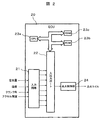
- FIG. 2 shows a control block showing the configuration of a control device for an internal combustion engine to which the present invention is applied.
- Input signals such as air amount information from the air flow sensor 1, humidity information from the humidity sensor 3, accelerator depression information from the accelerator opening sensor 12, angle information from the crank angle sensor 19, and the like are input circuits of the ECU 20 as control means. 21 is input.
- input signals are not limited to these, and will be described as appropriate.
- the input signal of each sensor is sent to the input port in the input / output port 22.
- the input information sent to the input port 22 is temporarily stored in the RAM 23c, and is arithmetically processed by the CPU 23a according to a predetermined control program.
- a control program describing the contents of the arithmetic processing is written in advance in the ROM 23b.
- Output information indicating the amount of operation to the fuel injection valve and the ignition coil that controls the internal combustion engine calculated according to the control program is temporarily stored in the RAM 23c, and then sent to the output port in the input / output port 22 for each. It is sent to a fuel injection valve and an ignition coil through a drive circuit.
- actuators other than these are also used for the internal combustion engine, description thereof is omitted here.
- the ignition control unit 24 is shown as a drive circuit, and the ignition control unit 24 controls the energization timing, the amount of discharge energy, and the like to the ignition coil.
- the ECU 20 includes the ignition control unit 24 for controlling the energization time and the amount of discharge energy to the ignition coil.
- the present invention is not limited to this, and a part of the ignition control unit 24 or All of the ignition control unit 24 may be mounted on a device different from the ECU 20.
- the ECU 20 calculates the discharge energy of the spark plug according to the detected air amount, crank angle, cooling water temperature, intake air temperature, humidity, etc., and energizes the ignition coil at an appropriate timing (flow time or ignition timing). Thus, the air-fuel mixture in the cylinder is ignited.
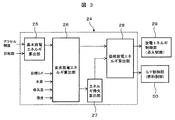
- FIG. 3 is a control block showing an outline of discharge energy control performed by the ignition control unit 24 in the ECU 20 which is a control device for the internal combustion engine according to the embodiment of the present invention.
- the basic discharge energy calculation unit 25 is based on the required torque calculated from the output information of the accelerator opening sensor 12 and the rotational speed of the internal combustion engine calculated from the output information of the crank angle sensor 19. It has a function to calculate the discharge period.
- the basic discharge energy amount and the basic discharge period calculated by the basic discharge energy calculation unit are input to the required discharge energy calculation unit 26 at the next stage.
- the required discharge energy calculation unit 26 corrects the basic discharge energy amount calculated by the basic discharge energy calculation unit based on the target gas fuel ratio G / F, the coolant temperature, the intake air temperature, the fresh gas humidity, and the like. And a function for obtaining a required amount of discharge energy.
- the target gas fuel ratio G / F is a ratio of the mass of a new gas (a gas in which air, EGR gas, water vapor, etc. are mixed) to the mass of fuel.
- the required discharge energy amount calculated by the required discharge energy calculation unit 26 is input to the energy gain / loss calculation unit 27 and the final discharge energy calculation unit 28 in the next stage.
- the calculation result obtained by the energy gain / loss calculator 27 is used, for example, for determination of correcting the required discharge energy amount or determination of switching the target gas fuel ratio G / F, and is set as a control flag.
- the final discharge energy calculation unit 28 corrects the required discharge energy amount obtained by the required discharge energy calculation unit 26 according to the control flag calculated by the energy gain / loss calculation unit 27 to obtain the final discharge energy amount. .
- the final discharge energy amount calculated by the final discharge energy calculation unit 28 is input to the discharge energy control unit 29 in the next stage.
- the gas fuel ratio G / F control unit 30 is supplied with information on the target gas fuel ratio G / F to be controlled from the final discharge energy calculation unit 28.
- the discharge energy control unit 29 has a function of controlling ignition by controlling a current value supplied to the ignition coil, an ignition timing, a passing time, a discharge pattern, and the like from the final discharge energy amount. Integrated into the coil.
- the discharge energy control unit 29 can also be configured to be included in the ignition control unit 24.
- the gas fuel ratio G / F control unit 30 receives the target gas fuel ratio G / F to be controlled from the final discharge energy calculation unit 28, and from the injector 13 according to the target gas fuel ratio G / F. A function of correcting and controlling the amount of fuel to be injected is provided.
- the target gas fuel ratio G / F is a standard gas fuel ratio G / F (for example, a theoretical gas mixture) or a fresh gas amount that is higher than the target gas fuel ratio G / F according to the control flag calculated by the energy gain / loss calculator 27.
- the gas fuel ratio G / F (lean air-fuel mixture) is high.
- This embodiment is based on each control block shown in FIG. 3, and details of each control block shown in FIG. 3 will be described below. However, before that, how to obtain the correction values of various parameters for correcting the influence of the basic discharge energy amount and external environmental factors will be described.
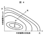
- FIG. 4 shows a basic discharge energy map for determining the basic discharge energy amount on a map created corresponding to the operating state of the internal combustion engine.
- the basic discharge energy amount tends to increase from a state where the output of the internal combustion engine is small to a state where the output of the internal combustion engine is large.
- the map of the basic discharge energy amount is constructed by experiments and simulations under the reference temperature Tref and the outside air conditions of dry air.
- the constructed basic discharge energy map shown in FIG. 4 is stored in advance in the ROM 23b shown in FIG.
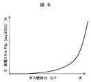
- FIG. 5 shows that the operating condition (engine output, engine speed) of the internal combustion engine is fixed, the horizontal axis indicates the gas fuel ratio G / F, and the vertical axis indicates the “basic discharge energy amount” and the “target gas fuel ratio G”. It is the map made into "discharge energy ratio” which is a ratio with “discharge energy amount required when controlling to / F”. This discharge energy ratio is a value obtained by dividing “the amount of discharge energy required when the target gas fuel ratio G / F is controlled” by the “basic discharge energy amount”.
- the discharge energy ratio is shown, but this may be the difference between the “discharge energy amount required when the target gas fuel ratio G / F is controlled” and the “basic discharge energy amount”.
- the required amount of discharge energy increases as the dilution of the air-fuel mixture increases, that is, as the gas fuel ratio G / F increases. Further, when the target gas fuel ratio G / F increases and approaches the state where the combustion of the air-fuel mixture in the cylinder becomes unstable, the required discharge energy amount suddenly increases. Thus, the target dilution of the air-fuel mixture (target gas fuel ratio G / F) and the value of the discharge energy have a substantially positive correlation.
- the characteristics of the required discharge energy with respect to the target gas fuel ratio G / F are different between the case where the new gas is only air and the case where the air is mixed with the EGR gas. In general, even if the gas / fuel ratio G / F is the same, if the fresh gas is only air, the required discharge energy amount is required compared to the case where the mixed gas is a stoichiometric EGR gas. There are few things.
- FIG. 5 shows characteristics under specific operating conditions, and the ROM 23b shown in FIG. 2 is provided with a discharge energy ratio map that defines the same relationship under a plurality of operating conditions. This discharge energy ratio map is also obtained by experiments and simulations.
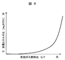
- FIG. 6 is necessary when controlling to the “basic discharge energy amount” and the “target effective gas fuel ratio G / F” similar to FIG. 5 under the conditions in which the operating conditions (engine output, engine speed) of the internal combustion engine are fixed. It is a map which shows "discharge energy ratio” which is ratio with "the amount of discharge energy to become”. This discharge energy ratio is a value obtained by dividing the “discharge energy amount required when the target gas effective fuel ratio G / F is controlled” by the “basic discharge energy amount”.
- the effective gas fuel ratio G / F is an index value calculated in consideration of the difference in the composition of fresh gas (oxygen, nitrogen, carbon dioxide, etc.).
- the effective gas fuel ratio G / F is “GbFeff”
- the target air-fuel ratio A / F is “AbFtar”
- the target EGR rate is “EGRtar”
- the correction for EGR When the coefficient is “ ⁇ ”, the effective gas fuel ratio G / F can be calculated by the following equation (1).
- GbFeff AbFtar ⁇ 1 + ⁇ EGRtar / (1 ⁇ EGRtar) ⁇ (1)
- the discharge energy ratio is shown in FIG. 6, as described in FIG. 5, “necessary when the target effective gas fuel ratio G / F is controlled. The difference between the “discharging energy amount” and the “basic discharging energy amount” is acceptable.
- FIG. 6 shows characteristics under specific operating conditions
- the ROM 23b shown in FIG. 2 includes a discharge energy ratio map that defines the same relationship under a plurality of operating conditions. This discharge energy ratio map is also obtained by experiments and simulations.
- FIG. 7 shows the change in the discharge energy ratio with respect to the absolute humidity of fresh air gas under the condition that the operating conditions (engine output, engine speed) of the internal combustion engine are fixed.
- the horizontal axis is absolute humidity
- the vertical axis is “required discharge energy amount at 0% absolute humidity” as a reference
- “target gas fuel ratio G / F values are“ large ”,“ medium ”,“ It is a map having a “discharge energy ratio” that is a ratio to the “required discharge energy amount in the case of“ small ””.
- This discharge energy ratio is a value obtained by dividing “the amount of discharge energy required to obtain the target gas effective fuel ratio G / F” by “the amount of required discharge energy at 0% absolute humidity”.
- a difference in the amount of discharge energy can be used.
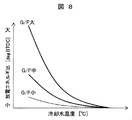
- FIG. 7 shows characteristics under specific operating conditions, and the ROM 23b shown in FIG. 2 is provided with a discharge energy ratio map that defines similar relationships under a plurality of operating conditions. This discharge energy ratio map is also obtained by experiments and simulations.
- FIG. 8 shows a change in the required discharge energy amount with respect to the cooling water temperature under the condition that the operating conditions (engine output and engine speed) of the internal combustion engine are fixed.
- the horizontal axis is the cooling water temperature
- the vertical axis is the “required discharge energy amount in the warm-up state” as a reference.
- the values of the target gas fuel ratio G / F are “large”, “medium”, It is a map with “discharge energy ratio” which is a ratio to “required discharge energy amount in the case of“ small ””.
- This discharge energy ratio is a value obtained by dividing “the amount of discharge energy necessary for obtaining the target gas fuel ratio G / F” by “the amount of discharge energy required in the warm-up state”.
- the difference in the amount of discharge energy can be used.
- the warm-up state described above refers to a state in which the coolant temperature has generally reached about 80 ° C.
- FIG. 8 shows characteristics under specific operating conditions, and the ROM 23b shown in FIG. 2 is provided with a discharge energy ratio map that defines similar relationships under a plurality of operating conditions. This discharge energy ratio map is also obtained by experiments and simulations.
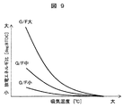
- FIG. 9 shows a change in the required discharge energy amount with respect to the intake air temperature under the condition in which the operating conditions (engine output, engine speed) of the internal combustion engine are fixed.
- the horizontal axis is the intake air temperature
- the vertical axis is the “required discharge energy amount of the intake air temperature under standard atmospheric conditions” as a reference.
- the values of the target gas fuel ratio G / F are “large”, “medium “Discharge energy ratio” which is a ratio to "required discharge energy amount in the case of" small ".
- This discharge energy ratio is a value obtained by dividing “the amount of discharge energy necessary to obtain the target gas fuel ratio G / F” by “the amount of required discharge energy of the intake air temperature under standard atmospheric conditions”.
- a difference in the amount of discharge energy can be used.
- the intake air temperature affects the cooling loss to the surrounding gas, the growth of flame nuclei during discharge, and the combustion reaction rate. Specifically, as the intake air temperature is lower, the cooling loss increases, and the rate of heat generation decreases because the growth rate of flame nuclei decreases. For this reason, the required discharge energy amount tends to increase as the intake air temperature decreases. Depending on the condition of the gas fuel ratio G / F, the required discharge energy amount varies even under the same intake air temperature condition, and the required discharge energy amount increases as the gas fuel ratio G / F increases.
- FIG. 9 shows characteristics under specific operating conditions, and the ROM 23b shown in FIG. 2 is provided with a discharge energy ratio map that defines similar relationships under a plurality of operating conditions. This discharge energy ratio map is also obtained by experiments and simulations.
- FIG. 10 shows a control flow of arithmetic processing executed by the basic discharge energy calculation unit 25 of FIG.
- step S10 the basic discharge energy amount is calculated from the required torque determined from the accelerator depression amount and the rotational speed of the internal combustion engine. In the calculation in this control step, it is possible to obtain from a predetermined basic discharge energy map by the rotational speed of the internal combustion engine and the torque of the internal combustion engine as shown in FIG. When the basic discharge energy amount is obtained, the process proceeds to step S11.
- step S11 the basic discharge period is determined from the required torque and the rotational speed of the internal combustion engine. In this calculation, similarly to the method of calculating the basic discharge energy amount, the rotation speed of the internal combustion engine and the required torque can be obtained from a predetermined basic discharge period map.
- the basic discharge energy amount and basic discharge period obtained in this control flow are sent to the required discharge energy calculation unit in the next stage, corrected and calculated based on parameters (disturbances) representing various external environmental factors.
- the amount of discharge energy is calculated.
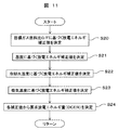
- FIG. 11 shows a control flow of arithmetic processing executed by the required discharge energy calculation unit 26 of FIG.
- step S20 a discharge energy correction value corresponding to the target gas fuel ratio G / F is determined. This can be obtained using the discharge energy ratio obtained from the discharge energy ratio map as shown in FIG. That is, the discharge energy ratio corresponding to the target gas fuel ratio G / F may be obtained from the discharge energy ratio map determined in accordance with the operation state, and the basic discharge energy amount is corrected by this discharge energy ratio, and the required amount is obtained. The amount of discharge energy is obtained.
- step S21 a discharge energy correction value corresponding to the humidity of fresh gas detected by the humidity sensor is determined. This can be obtained using the discharge energy ratio obtained from the discharge energy ratio map as shown in FIG.
- the correction value is obtained from the discharge energy ratio corresponding to the humidity for each target gas fuel ratio G / F.
- the map storage capacity is reduced, a correction value for each target gas fuel ratio G / F can be obtained by interpolating between the data for each of the plurality of gas fuel ratios G / F.
- step S22 a discharge energy correction value corresponding to the coolant temperature is determined. This can be obtained by using the discharge energy ratio obtained from the discharge energy ratio map as shown in FIG. Again, the correction value is obtained from the discharge energy ratio corresponding to the coolant temperature for each target gas fuel ratio G / F. Further, as described in step S21, when the storage capacity of the map is reduced, interpolation between data for each of the plurality of gas fuel ratios G / F is performed, so that the data for each target gas fuel ratio G / F is interpolated. A correction value can be obtained. When the discharge energy ratio corresponding to the cooling water temperature is obtained, the process proceeds to step S23.
- step S23 a discharge energy correction value corresponding to the intake air temperature is determined. This can be obtained by using the discharge energy ratio obtained from the discharge energy ratio map as shown in FIG. Here, the correction value is obtained from the discharge energy ratio corresponding to the intake air temperature for each target gas fuel ratio G / F. Similarly, as described in step S21, when reducing the storage capacity of the map, by interpolating between the data for each of the plurality of gas fuel ratios G / F, the interval between the target gas fuel ratios G / F. The correction value can be obtained. When the discharge energy ratio corresponding to the cooling water temperature is obtained, the process proceeds to step S24.
- step S24 a required discharge energy amount (DCER) is determined from the respective correction values obtained in steps S20 to S23.
- the required discharge energy amount (DCER) is obtained by the product of the basic discharge energy amount and the total correction value obtained by adding these correction values. It has been.
- a required discharge energy amount (DCER) can be obtained.
- the required discharge energy amount can be obtained in consideration of the disturbance that affects the formation of the flame kernel after the discharge. Therefore, even if the target gas fuel ratio G / F changes under various conditions, the required discharge energy can be set so that stable combustion can be realized. Can be suppressed.
- the required discharge energy amount obtained in this control flow is sent to the energy gain / loss calculation unit 27 and the final discharge energy calculation unit 28 in the next stage.
- FIG. 12 shows a control flow of arithmetic processing executed by the energy gain / loss calculation unit 27 in FIG.
- step S30 a fuel reduction amount ⁇ FC1 for controlling to the target gas fuel ratio G / F is calculated.
- the fuel reduction amount ( ⁇ FC1) when controlling to the target gas fuel ratio G / F can be determined from the relationship shown in FIG. Although the fuel reduction amount ⁇ FC1 depends on the operating conditions and the characteristics of the internal combustion engine, increasing the target gas fuel ratio G / F (in the lean direction) increases the fuel reduction amount, and a predetermined target gas fuel ratio G / F. It tends to saturate when the temperature exceeds.
- Fuel reduction amount per unit time (1 second) ( ⁇ FC1) [g / s] from fuel reduction amount (FR) [g / kWh] per hour when controlling to the target gas fuel ratio G / F ] Is given by the following equation (2) when the output (We) [W] of the internal combustion engine is used.
- ⁇ FC1 FR ⁇ We / 3600 (2)
- the obtained fuel reduction amount ⁇ (FC1) is a fuel reduction amount determined from the target gas fuel ratio G / F.
- the process proceeds to the next step S31.
- step S31 the fuel increase amount ( ⁇ FC2) necessary for obtaining the required discharge energy amount is calculated.
- Mechanical efficiency for example, conversion efficiency (coil efficiency) ⁇ co of discharge energy amount for ignition with respect to input energy amount, thermal efficiency ⁇ i of internal combustion engine, belt transmission efficiency ⁇ t, alternator power generation efficiency ⁇ a, battery charging efficiency ⁇ c, supply from battery
- conversion efficiency coil efficiency
- thermal efficiency ⁇ i of internal combustion engine thermal efficiency ⁇ i of internal combustion engine
- belt transmission efficiency ⁇ t alternator power generation efficiency ⁇ a
- battery charging efficiency ⁇ c supply from battery
- the energy consumption Qc [J] required per combustion cycle to obtain the required discharge energy amount DCER [J] is given by the following equation (3) per discharge. .
- step S32 the magnitude relationship between the fuel reduction amount ( ⁇ FC1) obtained in step S30 and the fuel increase amount ( ⁇ FC2) obtained in step S31 is compared.
- the fuel reduction amount ( ⁇ FC1) is larger than the fuel increase amount ( ⁇ FC2), the process proceeds to step 33.
- the fuel increase amount ( ⁇ FC2) is larger than the fuel reduction amount ( ⁇ FC1), the process proceeds to step S34.
- Step S33, S34 Then, according to the determination result, in step S33, the target gas fuel ratio G / F control execution flag (CF_GbF) is set to “ON”, and in step S34, the target gas fuel ratio G The / F control execution flag (CF_GbF) is set to “OFF”.
- the fuel reduction amount when the target gas fuel ratio G / F is controlled is compared with the fuel increase amount required to obtain the required discharge energy amount, and the target gas fuel ratio G When the internal combustion engine is operated at / F, it can be determined whether or not overall fuel consumption reduction can be realized.
- FIG. 13 shows a control flow of arithmetic processing executed by the final discharge energy calculation unit 28 of FIG.
- a basic discharge energy amount (MFDE) is determined by correcting the basic discharge energy amount obtained by the basic discharge energy calculation unit 25 based on the intake temperature, humidity, etc. of the fresh air gas. .
- This corrected basic discharge energy amount (MFDE) is the discharge energy amount when the target gas fuel ratio G / F is not switched. Therefore, in this correction calculation, correction by the target gas fuel ratio G / F is not performed.
- the process proceeds to step S41.
- step S41 the amount of energy input to the ignition coil is determined based on the corrected basic discharge energy amount (MFDE) obtained in step S40 and the required discharge energy amount (DCER) obtained in step S24 of FIG. decide. Details of the control step S41 will be described with reference to the control flow shown in FIG. When the calculation of step S41 ends, the process proceeds to step S42.
- MFDE corrected basic discharge energy amount
- DCER required discharge energy amount
- step S42 it is determined whether the target gas fuel ratio G / F control execution flag (CF_GbF) obtained by the energy loss calculation unit 27 is “ON” or “OFF”. If the target gas fuel ratio G / F control execution flag (CF_GbF) is “ON”, the process proceeds to step S43. If the gas fuel ratio G / F control execution flag (CF_GbF) is “OFF”, the process proceeds to step S44. Transition.
- Step S43 When the target gas fuel ratio G / F control execution flag (CF_GbF) is “ON”, the target gas fuel ratio G / F is set to be changed. As a result, the air-fuel mixture is controlled to be in a lean state, and fuel efficiency is improved.
- Step S44 On the other hand, when the target gas fuel ratio G / F control execution flag (CF_GbF) is “OFF”, the target gas fuel ratio G / F is not changed.
- the ratio G / F is set to the standard gas fuel ratio G / F, for example, the stoichiometric air-fuel ratio. Therefore, it can be set as the environment which can be ignited even if discharge energy amount is reduced.
- step S41 the method for determining the amount of discharge energy to the ignition coil executed in step S41 will be described in detail with reference to FIG.
- step S50 it is determined whether the target gas fuel ratio G / F control execution flag (CF_GbF) is ON or OFF. If it is OFF, the process proceeds to step S55. If it is ON, the process proceeds to step S51.
- C_GbF target gas fuel ratio G / F control execution flag
- step S51 a discharge period (DCDR) based on the rotational speed is calculated.
- DCDR discharge period
- the flow of the air-fuel mixture in the cylinder is strengthened according to the moving speed of the piston, so that re-discharge during discharge occurs and the substantial discharge period is shortened.
- the period during which the discharge energy is supplied is determined in consideration of the fact that the period in which the piston is present at a piston position suitable for ignition becomes shorter as the rotational speed increases.
- the discharge period may be set to be shortened according to the rotational speed.
- the reference discharge time Tref [sec] at the rotational speed of 1000 rpm of the internal combustion engine is stored in the ROM 23b of the ECU 20, and this is used as a reference.
- the discharge period (DCDR) can be obtained by calculating from the rotation speed Ne to be calculated as shown in the following equation (5).
- DCDR (Tref ⁇ 1000) / Ne (5)
- the process proceeds to step S52.
- step S52 the maximum amount of discharge energy (DCEM) that can be generated within the same period as the discharge period (DCDR) is calculated using the mounted ignition coil 16. This can be obtained from the design specifications of the mounted ignition coil 16.
- DCEM maximum discharge energy amount
- step S53 the maximum discharge energy amount (DCEM) obtained in step S52 is compared with the required discharge energy amount (DCER) obtained in step S24 of FIG. In this control step, if it is determined that the maximum discharge energy amount (DCEM) is large, the process proceeds to step S56, and if it is determined that the required discharge energy amount (DCER) is large, the process proceeds to step S54.
- Step S54 If the required discharge energy amount (DCER) is large in the determination in step S53, it indicates that the discharge with the required discharge energy amount cannot be realized. Therefore, in step S54, the target gas fuel ratio G / F control execution flag (CF_GbF) is reset to OFF. When the target gas fuel ratio G / F control execution flag (CF_GbF) is turned OFF, the process proceeds to step S55.
- DCER required discharge energy amount
- step S55 the target gas fuel ratio G / F control execution flag (CF_GbF) is turned OFF in steps S50 and S54, so the corrected basic discharge energy amount obtained in step S40 of FIG. (MFDE) is set as the final discharge energy amount.
- the corrected basic discharge energy amount (MFDE) is set, the process proceeds to step S57.
- Step S56 If it is determined in step S53 that the maximum discharge energy amount (DCEM) is larger than the required discharge energy amount (DCER), it is assumed that the discharge can be performed with the required discharge energy amount (DCER). In determination step S56, the required discharge energy amount (DCER) is set as the final discharge energy amount. The process proceeds to step S57 where the final discharge energy amount is set.
- DCEM maximum discharge energy amount
- DCER required discharge energy amount
- step S57 a dischargeable energy amount (DENO) for determining whether or not additional supply of discharge energy after discharge at the spark plug is necessary is calculated.
- a dischargeable energy amount (DENO) that can be discharged during the discharge period (DDDR) without any additional current after the start of discharge is calculated.
- the dischargeable energy amount (DENO) can be obtained from the design specifications of the ignition coil, the amount of current flowing through the primary coil before discharge, and the discharge period (DDDR).
- FIG. A normal ignition coil energizes the primary coil before charging and fills it with electrical energy, and the ignition control device cuts off the current flowing through the primary coil. As a result, the magnetic flux passing through the coil changes, a high voltage is generated in the secondary coil, and a discharge is generated in the plug gap of the spark plug 17.
- the ignition coil shown in FIG. 16 is composed of two coils: a first coil 16PA as a primary coil and a second coil 16PB as an additional coil.
- the ignition coil includes a first coil 16PA and a second coil 16PB.
- the additional current is passed through the second coil 16PB by passing an additional current so as to increase the magnetic flux formed in the second coil 16PB after the current is cut off. Can be increased.
- Step S58 When the dischargeable energy amount (DENO) is obtained in step S57, in step S58, the dischargeable energy amount (DENO) that can be discharged without additional current and the required discharge energy amount (DCER) that is the final discharge energy amount. ). When the required discharge energy (DCER) is larger, the process proceeds to step S59, and when the discharge energy (DENO) is larger, the process proceeds to step S61.
- step S59 a target current value to be generated on the secondary side of the ignition coil is determined.
- the process proceeds to step S60.
- step S60 the first coil 16 of the primary side coil 16 as shown in FIG. 16 is supplied so that the target current value (Itar) obtained in step S59 can flow during the discharge period (DDDR) or longer.
- the energization time and additional current pattern (time change) of the two coils 16PB are determined.
- the control flow is terminated by exiting to the end.
- the amount of additional current is controlled so that the discharge energy has a positive correlation with the rotational speed.
- Step S61 Since it is determined in step S58 that the required discharge energy amount (DCER) is smaller than the discharge energy amount (DEN0) that can be discharged without additional current, in step S61, the final amount without additional current is reached.
- the energization time to the primary coil before discharge is calculated. The amount of discharge energy increases as the current application time before discharge increases, and this relationship can be experimentally determined as coil characteristics, and these relationships can be stored in the ECU 20 in advance. . Thereafter, the process proceeds to step S62, and the amount of current to be applied to the primary coil side after energization is set to “0”.
- the corrected basic discharge energy amount (MFDE) as the final discharge energy amount obtained in step S55 is also calculated by the same method as in step S61.
- FIG. 17 shows a second control flow executed by the required discharge energy calculation unit 26 of FIG.
- step S70 the target effective gas fuel ratio G / F is determined from the target gas fuel ratio G / F and the humidity. This is regarded as a gas amount including the humidity detected by the humidity sensor 3, and when the target gas fuel ratio G / F is achieved, the gas fuel ratio G / F formed in the cylinder is re-evaluated to achieve the target.
- the effective gas fuel ratio is G / F.
- the target effective gas fuel ratio G / F is “GbFeff”, the target air-fuel ratio A / F is “AbFtar”, the target EGR rate is “EGRtar”, the EGR correction coefficient is “ ⁇ ”, the absolute humidity is “AH”,
- the correction coefficient relating to humidity is “ ⁇ ”
- the target effective gas fuel ratio G / F can be calculated by the following equation (7).
- GbFeff AbFtar (1 + ⁇ EGRtar / (1 ⁇ EGRtar) + ⁇ AH) (7)
- the process proceeds to step S71.
- step S71 a discharge energy correction value corresponding to the target effective gas fuel ratio G / F is determined. This can be obtained by using the discharge energy ratio obtained from the discharge energy ratio map as shown in FIG. That is, it is only necessary to obtain a discharge energy ratio corresponding to the target effective gas fuel ratio G / F from the discharge energy ratio map determined corresponding to the operating state, and the basic discharge energy amount is corrected by this discharge energy ratio, The required amount of discharge energy is obtained.
- the discharge energy correction value is obtained, the process proceeds to the next step.
- Step S72 corresponds to step S22 in FIG. 11
- step S73 corresponds to step S23 in FIG. 11
- step S74 corresponds to step S24 in FIG. Therefore, the explanation is omitted.
- the discharge energy ratio map set separately for the target gas fuel ratio G / F and humidity can be obtained. Since the two discharge energy ratio maps can be integrated, the memory capacity of the ROM 26d of the ECU 20 can be reduced.
- FIG. 18 shows a second control flow executed by the energy gain / loss calculation unit 27 of FIG.
- step S80 a fuel reduction amount ⁇ FC1 when the target effective gas fuel ratio G / F is controlled is calculated.
- the fuel reduction amount ( ⁇ FC1) when controlling to the target effective gas fuel ratio G / F can be determined from the relationship shown in FIG. Although the fuel reduction amount ⁇ FC1 depends on the operating conditions and the characteristics of the internal combustion engine, increasing the target effective gas fuel ratio G / F (in the lean direction) increases the fuel reduction amount, and a predetermined target effective gas fuel ratio G When it exceeds / F, it tends to be saturated.
- Step S81 corresponds to step S31 of FIG. 12
- step S82 corresponds to step S32 of FIG. 12
- step S83 corresponds to step of FIG.
- step S84 corresponds to step S34 in FIG.
- map data and the like are compared with those of the first embodiment by using the target effective gas fuel ratio G / F for the calculation of the fuel reduction amount of the internal combustion engine. Can be reduced.
- the ignition coil for inducing the discharge voltage for generating the discharge spark in the spark plug, the discharge voltage generating unit for generating the discharge voltage in the ignition coil, the discharge voltage
- the ignition control means includes basic discharge energy calculation means for determining the basic discharge energy amount generated by the generator according to the operating condition of the internal combustion engine, and the ignition control means converts the air-fuel mixture in the cylinder of the internal combustion engine to a target gas fuel ratio.
- the basic discharge energy amount obtained by the basic discharge energy calculation means is corrected in accordance with the state of the air-fuel mixture in the cylinder determined by external environmental factors. It is set as the structure provided with the discharge energy correction
- an ignition coil for inducing a discharge voltage for generating a discharge spark in the spark plug, a discharge voltage generator for generating a discharge voltage in the ignition coil, and a discharge voltage generator Ignition control means having basic discharge energy calculation means for determining the basic discharge energy amount generated in accordance with the operating conditions of the internal combustion engine, and the ignition control means converts the air-fuel mixture in the cylinder of the internal combustion engine to the target gas fuel ratio G /
- the basic discharge obtained by the basic discharge energy calculation means Discharge energy correction means for increasing the energy amount is provided.
- the amount of discharge energy is increased when the amount of fuel reduction due to dilution combustion exceeds the amount of fuel consumption that increases in order to obtain the discharge energy required for discharging the spark plug, so that the amount of discharge energy is diluted. Combustion of the air-fuel mixture can be stabilized and fuel consumption performance can be improved.
- this invention is not limited to the above-mentioned Example, Various modifications are included.
- the above-described embodiments have been described in detail for easy understanding of the present invention, and are not necessarily limited to those having all the configurations described.
- a part of the configuration of one embodiment can be replaced with the configuration of another embodiment, and the configuration of another embodiment can be added to the configuration of one embodiment.
- SYMBOLS 1 Air flow sensor, 2 ... Electronically controlled throttle, 3 ... Humidity sensor, 4 ... Supercharger, 4a ... Compressor, 4b ... Turbine, 5 ... Variable valve, 6 ... Intake manifold, 7 ... Intercooler, 9 ... Air-fuel ratio sensor DESCRIPTION OF SYMBOLS 10 ... Three-way catalyst, 11 ... Waste gate valve, 12 ... Accelerator opening sensor, 13 ... Injector, 14 ... Cylinder, 15 ... Exhaust pipe, 16 ... Ignition coil, 17 ... Ignition plug, 18 ... Cooling water temperature sensor, 19 ... crank angle sensor, 20 ... ECU, 21 ... input circuit, 22 ...
Landscapes
- Engineering & Computer Science (AREA)
- Chemical & Material Sciences (AREA)
- Combustion & Propulsion (AREA)
- Mechanical Engineering (AREA)
- General Engineering & Computer Science (AREA)
- Combined Controls Of Internal Combustion Engines (AREA)
- Ignition Installations For Internal Combustion Engines (AREA)
- Electrical Control Of Air Or Fuel Supplied To Internal-Combustion Engine (AREA)
Abstract
内燃機関の制御目標として与えられた目標ガス燃料比に制御場合の必要となる放電エネルギ量を正確に求めることができる内燃機関の制御装置を提供することにある。 点火プラグに放電火花を発生させるための放電電圧を誘起する点火コイル16と、点火コイル16に放電電圧を発生させる放電電圧発生部29と、放電電圧発生部29で発生させる基本放電エネルギ量を内燃機関の運転条件に応じて定める点火制御手段24を備え、点火制御手段24は、気筒内の混合気を目標ガス燃料比G/Fに制御するのに必要となる最終放電エネルギ量を、外的な環境要因によって定まる気筒内の混合気の状態に対応して基本補正エネルギ量を補正して求める放電エネルギ補正手段26~28を備える。
Description
本発明は内燃機関の制御装置に係り、特に点火コイルを利用して点火プラグに火花放電を発生して混合気に着火する火花点火式の内燃機関に使用される内燃機関の制御装置に関するものである。
自動車の燃費性能を向上するためには種々の方法があるが、内燃機関の燃料消費量を低減することが重要である。燃料消費量の低減には、内燃機関の運転中に発生するポンプ損失、冷却損失、排気損失、といった各種損失の低減が有効であり、ポンプ損失、冷却損失の低減手段として、燃料と空気の比率を量論混合比(理論混合比)に比べて希薄にして燃焼させる希薄燃焼や、燃焼ガスの一部を吸気側に戻して燃料と空気の混合気を希釈するEGR(Exhaust Gas Recirculation)ガスを活用した燃焼方式がある。以下では、希薄燃焼やEGRガスを活用した燃焼方式をまとめて「希釈燃焼」と記載する。
この希釈燃焼を用いると、希釈燃焼を用いない場合に比べて吸気管圧力を上げることができるので、内燃機関の負荷の低い条件でのポンプ損失の低減や、熱容量を増加させることで、混合気の燃焼温度を低下して冷却損失の低減を図ることができる。また、内燃機関の負荷の高い条件では、EGRガスを導入することによる自着火反応に至る反応進行が抑制されることで、異常燃焼の発生が抑制できる。これによって点火時期を最適時期に近づけるように進角することができるため、排気損失の低減ができるようになる。
さて、燃料消費量を低減するためには、運転条件に応じて適切な混合気の希釈度(以下に示すガス燃料比)を設定する必要が有る。混合気の希釈度は、空気やEGRガスからなる混合ガスの質量和と燃料の質量の比(ガス燃料比G/F)、空気と燃料の質量比(空燃比A/F)、吸気ガス中のEGRの割合(EGR率)で評価することが多い。
希釈度の大きな条件(希薄な混合気の状態)で失火を避けて燃焼を実現するためには、燃料の相対的な濃度が小さくなっているので、火花点火時に点火プラグから気筒内の混合気に供給する放電エネルギ量を増加させる必要が有る。また、希釈度の大きな条件で安定的な燃焼を実現するために、内燃機関の気筒内の混合気の乱流強度や流速を、従来に比べて増加させる必要がある。
しかしながら、乱流強度や流速が大きくなると、点火プラグでの放電の吹き消え等の現象による失火発生の可能性が生じるため、併せて火花点火時に点火プラグから気筒内混合気に供給する放電エネルギ量を増加させる必要がある。
点火プラグから気筒内の混合気に供給する放電エネルギ量を増加する手段として、例えば、特開2015-200284号公報(特許文献1)に記載されている内燃機関用点火装置がある。この特許文献1は、点火プラグによる火花放電開始後に、一次側コイルの一部に電気的エネルギを追加投入し、2次側コイルに発生させる放電エネルギ量を増加させる点火装置を提案している。また、各種の外乱を考慮して放電エネルギ量の増加補正を行なう手段として、例えば、特開2015-194124号公報(特許文献2)に記載されている点火装置がある。この特許文献2は、外乱によって要求点火エネルギが変化すると放電エネルギ量を増加させる点火装置を提案している。
そして、特許文献1においては、1次側コイルの巻き線を工夫することで、点火コイルでの発熱を抑制し、1次側に投入できるエネルギ量を増加して放電エネルギを増加させることを開示している。また、特許文献2においては、要求放電エネルギに影響を与える現象が複数ある場合に、放電エネルギをどのように与えるかについての方法を開示している。
しかしながら、これらの特許文献においては、外的な環境要因と実現すべき混合気の希釈度(目標ガス燃料比G/F)が与えられた場合の、放電エネルギの要求値の決定方法について考慮されていないものである。また、点火プラグの放電を行なうために必要となる電力のために消費される燃料消費量(機械的エネルギ消費量)が、希釈燃焼を実現することで得られる燃料低減量(エネルギ低減量)を上回る現象が生じる場合の対応策についても考慮されていないものである。したがって、これらの課題に対応する制御方法の立案が強く望まれている。
本発明の第1の目的は、内燃機関の制御目標として与えられた目標ガス燃料比に制御する場合に、外的な環境要因を考慮して放電エネルギ量を正確に求めることができる内燃機関の制御装置を提供することにある。
本発明の第2の目的は、希釈燃焼を実現することで得られる燃料低減量が点火プラグの放電を行なうために必要となる電力のために消費される燃料消費量を上回る時の放電エネルギ量を正確に求めることができる内燃機関の制御装置を提供することにある。
本発明の第1の特徴は、点火プラグに放電火花を発生させるための放電電圧を誘起する点火コイルと、点火コイルに放電電圧を発生させる放電電圧発生部と、放電電圧発生部で発生させる基本放電エネルギ量を内燃機関の運転条件に応じて定める基本放電エネルギ算出手段を有する点火制御手段を備え、点火制御手段は、内燃機関の気筒内の混合気を目標ガス燃料比G/Fに制御するのに必要となる放電エネルギ量を、外的な環境要因によって定まる気筒内の混合気の状態に対応して、基本放電エネルギ算出手段で求められた基本放電エネルギ量を補正して求める放電エネルギ補正手段を備える、ところにある。
本発明の第2の特徴は、点火プラグに放電火花を発生させるための放電電圧を誘起する点火コイルと、点火コイルに放電電圧を発生させる放電電圧発生部と、放電電圧発生部で発生させる基本放電エネルギ量を内燃機関の運転条件に応じて定める基本放電エネルギ算出手段を有する点火制御手段を備え、点火制御手段は、内燃機関の気筒内の混合気を目標ガス燃料比G/Fに制御することで得られる燃料低減量が、点火プラグでの放電を行なうために必要となる電力のために消費される燃料消費量を上回る場合は、基本放電エネルギ算出手段で求めた基本放電エネルギ量を増加補正する放電エネルギ補正手段を備える、ところにある。
本発明によれば、外的な環境要因(外乱)を考慮した上で、目標とするガス燃料比G/Fに制御するために必要となる放電エネルギ量を正確に求めることができる。
また、希釈燃焼による燃料低減量が点火プラグの放電を行なうために必要となる放電エネルギを得るために増加する燃料消費量を上回る場合に、放電エネルギ量を増加するので、希釈された混合気の燃焼を安定化させることができ、また、燃費性能を向上できるものである。
以下、本発明の実施形態について図面を用いて詳細に説明するが、本発明は以下の実施形態に限定されることなく、本発明の技術的な概念の中で種々の変形例や応用例をもその範囲に含むものである。
以下、図面を参照しながら、本発明の実施形態について説明するが、以下に示す実施形態に共通の構成を図1乃至図4を用いて説明する。
図1は、自動車に使用される火花点火式内燃機関のシステム構成を示しており、ガソリン燃料を気筒内に直接噴射する筒内燃料噴射弁を備えている。
内燃機関ENGは、火花点火燃焼を実施する自動車用の筒内噴射式内燃機関である。吸入空気量及び吸気温度を計測するエアフローセンサ1と、吸気湿度検出手段である湿度センサ3と、吸気を過給するための過給機のコンプレッサ4aと、吸気を冷却するためのインタークーラ7と、吸気管圧力を調整する電子制御スロットル2が吸気管の各々の適宜位置に備えられている。
ここで、湿度センサ3は相対湿度及び絶対湿度が検出可能なセンサである。また、内燃機関ENGには、各気筒のシリンダ14の中に燃料を噴射する燃料噴射装置(以下、インジェクタと記載する)13と、点火エネルギを供給する点火装置(以下、点火コイル16、点火プラグ17)が気筒ごとに備えられている。また、気筒内に流入する混合気、または気筒内から排出する排気ガスを調整する可変バルブ5が、シリンダヘッドに備えられている。可変バルブ5を調整することにより、全気筒の吸気量および内部EGR量を調整する。
また、図示していないが燃料噴射装置13に高圧燃料を供給するための高圧燃料ポンプが燃料配管によって燃料噴射装置13と接続されており、燃料配管中には、燃料噴射圧力を計測するための燃料圧力センサが備えられている。また、内燃機関のピストン位置を検知するためのクランク角度センサ19が取り付けられている。クランク角度センサ19の出力情報はECU20に送られる。
更に、排気エネルギによって過給機のコンプレッサ4aに回転力を与えるためのタービン4bと、タービンに流れる排気流量を調整するための電子制御ウェイストゲート弁11と、排気を浄化する三元触媒10と、空燃比検出器の一態様であって、三元触媒10の上流側にて排気ガスの空燃比を検出する空燃比センサ9とが排気管15の各々の適宜位置に備えられる。また、図示していないが内燃機関を巡る冷却水の温度を計測する温度センサ18が備えられている。
エアフローセンサ1、湿度センサ3、温度センサ18と空燃比センサ9から得られる出力情報は、内燃機関を制御するコントロールユニット(ECU)20に送られる。また、アクセル開度センサ12から得られる出力情報がECU20に送られている。アクセル開度センサ12は、アクセルペダルの踏み込み量、すなわち、アクセル開度を検出する。
ECU20は、アクセル開度センサ12の出力情報に基づいて、要求トルクを演算する。すなわち、アクセル開度センサ12は、内燃機関への要求トルクを検出する要求トルク検出センサとして用いられる。また、ECU20は、クランク角度センサの出力情報に基づいて、内燃機関の回転速度を演算する。ECU20は、上記各種センサの出力情報から得られる内燃機関の運転状態に基づき、空気流量、燃料噴射量、点火時期、燃料圧力等の内燃機関の主要な作動量を最適に演算する。
ECU20で演算された燃料噴射量は開弁パルス信号に変換され、インジェクタ13に送られる。また、ECU20で演算された点火時期で点火されるように、点火信号が点火コイル16に送られる。また、ECU20で演算されたスロットル開度は、スロットル駆動信号として電子制御スロットル2に送られる。
吸気管から吸気バルブを経てシリンダ14内に流入した空気に対し、燃料が噴射され、混合気を形成する。混合気は所定の点火時期で点火プラグ16から発生される火花により爆発し、その燃焼圧によりピストンを押し下げて内燃機関の駆動力となる。更に、爆発後の排気ガスは排気管15を経て、三元触媒10に送りこまれ、排気成分は三元触媒10内で浄化され、外部へと排出される。
このような内燃機関システムにおいて、次に本実施形態の詳細について説明する。図2は、本発明が適用される内燃機関の制御装置の構成を示す制御ブロックを示している。エアフローセンサ1からの空気量情報、湿度センサ3からの湿度情報、アクセル開度センサ12からのアクセル踏込情報、クランク角センサ19からの角度情報等の入力信号は、制御手段であるECU20の入力回路21に入力される。但し、入力信号はこれらだけに限られるものではないので、適宜に追加して説明する。
入力された各センサの入力信号は、入出力ポート22内の入力ポートに送られる。入力ポート22に送られた入力情報は、RAM23cに一時保管され、CPU23aで、所定の制御プログラムにしたがって演算処理される。演算処理の内容を記述した制御プログラムは、ROM23bに予め書き込まれている。
制御プログラムにしたがって演算された内燃機関を制御する燃料噴射弁や点火コイルへの作動量を示す出力情報は、RAM23cに一時保管された後、入出力ポート22内の出力ポートに送られ、夫々の駆動回路を経て燃料噴射弁や点火コイルへ送られる。尚、内燃機関にはこれら以外のアクチュエータも使用されているが、ここでは説明を省略する。
本実施形態の場合は、駆動回路として点火制御部24を示しており、点火制御部24は、点火コイルへの通電時期や放電エネルギ量等を制御する。本実施形態においては、ECU20内に点火コイルへの通電時間や放電エネルギ量を制御するための点火制御部24を備えているが、これに限るものではなく、点火制御部24の一部、または、点火制御部24の全てがECU20とは別の装置に実装されていても差し支えないものである。
そして、ECU20は検出した空気量、クランク角、冷却水温、吸気温度、湿度等に応じて、点火プラグの放電エネルギを演算して適切なタイミング(通流時間や点火時期)に点火コイルへ通電して、気筒内の混合気に着火するものである。
図3は、本発明の実施形態になる内燃機関の制御装置であるECU20内の点火制御部24で実施される放電エネルギ制御の概要を示す制御ブロックである。
基本放電エネルギ算出部25は、アクセル開度センサ12の出力情報から算出された要求トルクと、クランク角センサ19の出力情報から算出された内燃機関の回転速度に基いて、基本電流エネルギ量と基本放電期間を算出する機能を備えている。基本放電エネルギ算出部で算出された基本放電エネルギ量と基本放電期間は、次段の要求放電エネルギ算出部26に入力される。
要求放電エネルギ算出部26は、基本放電エネルギ算出部で算出された基本放電エネルギ量を、目標ガス燃料比G/F、冷却水温度、吸気温度、新気ガスの湿度等に基づいて補正して、要求放電エネルギ量を求める機能を備えている。ここで、目標ガス燃料比G/Fは、新規ガス(空気とEGRガス及び水蒸気等が混合された気体)の質量と燃料の質量の比である。要求放電エネルギ算出部26で算出された要求放電エネルギ量は、次段のエネルギ得失算出部27と、最終放電エネルギ算出部28に入力される。
エネルギ得失算出部27は、要求放電エネルギ算出部で算出した要求放電エネルギ量を得るための電力に必要な燃料消費量(=機械エネルギ消費量)の増加量と、混合気の濃度を目標ガス燃料比G/Fに制御した時の燃料低減量とから、目標ガス燃料比G/Fに制御した時の燃費の得失を算出する機能を備えている。このエネルギ得失算出部27で得られる演算結果は、例えば、要求放電エネルギ量を補正する判断や、目標ガス燃料比G/Fを切り換える判断に使用されものであり、制御フラグとして設定される。
最終放電エネルギ算出部28は、要求放電エネルギ算出部26で求められた要求放電エネルギ量を、エネルギ得失算出部27で演算された制御フラグにしたがって補正して、最終放電エネルギ量を求めるものである。最終放電エネルギ算出部28で算出された最終放電エネルギ量は、次段の放電エネルギ制御部29に入力される。尚、ガス燃料比G/F制御部30には、最終放電エネルギ算出部28から制御すべき目標ガス燃料比G/Fの情報が送られている。
放電エネルギ制御部29は、最終放電エネルギ量から点火コイルへの通電電流値、点火時期、通流時間、放電パターン等を制御して点火制御する機能を備えており、放電エネルギ制御部29は点火コイルに一体化されている。尚、放電エネルギ制御部29は点火制御部24に含まれるように構成することもできる。
また、ガス燃料比G/F制御部30は、最終放電エネルギ算出部28から制御すべき目標ガス燃料比G/Fが送られてきており、この目標ガス燃料比G/Fにしたがってインジェクタ13から噴射される燃料量を補正制御する機能を備えている。後述するように、エネルギ得失算出部27で演算された制御フラグによって、目標ガス燃料比G/Fが標準ガス燃料比G/F(例えば、理論混合気)か、或いはこれよりも新気ガス量が多いガス燃料比G/F(希薄混合気)に設定されるものである。
本実施形態は図3に示す各制御ブロックを基本構成としており、以下、図3に示す各制御ブロックの詳細を説明する。ただ、その前に基本となる放電エネルギ量、及び外的な環境要因による影響を補正するための各種パラメータの補正値の求め方について説明する。
図4は、内燃機関の運転状態に対応して作成したマップ上で基本放電エネルギ量を定める基本放電エネルギマップを示している。そして、内燃機関の出力が小さい状態から内燃機関の出力が大きい状態にかけて、基本放電エネルギ量は増加する方向にある。ただし、負荷(トルク)が低く、回転数が小さい条件では、気筒内の混合気の燃焼が不安定化しやすいため、特定の領域で基本放電エネルギが増加する特性とされている。ここで、基本放電エネルギ量のマップは基準温度Tref、乾燥空気の外気条件下で、実験やシミュレーションで構築したものである。尚、構築した図4に示す基本放電エネルギマップは、図2に示すROM23bに予め保存されている。
図5は、内燃機関の運転条件(機関出力、機関回転数)を固定した条件において、横軸をガス燃料比G/Fとし、縦軸を「基本放電エネルギ量」と「目標ガス燃料比G/Fに制御した時に必要となる放電エネルギ量」との比である「放電エネルギ比」にしたマップである。この放電エネルギ比は、「目標ガス燃料比G/Fに制御した時に必要となる放電エネルギ量」を「基本放電エネルギ量」で除した値である。
尚、図5では、放電エネルギ比としているが、これは「目標ガス燃料比G/Fに制御した時に必要となる放電エネルギ量」と「基本放電エネルギ量」の差としても差し支えないものである。
そして、混合気の希釈度が大きい、つまりガス燃料比G/Fが大きくなるにつれて、要求される放電エネルギ量は増加するようになる。また、目標ガス燃料比G/Fが大きくなって、気筒内の混合気の燃焼が不安定化する状態に近づくと要求放電エネルギ量は急激に増加するようになる。このように、混合気の目標希釈度(目標ガス燃料比G/F)と放電エネルギの値は概ね正の相関性を有している。
尚、目標ガス燃料比G/Fに対する要求放電エネルギの特性は、新規ガスが空気だけの場合と、空気とEGRガスが混合された混合ガスの場合で異なるものである。一般的に、同じガス燃料比G/Fの条件であっても、新気ガスが空気だけの場合は、混合ガスがストイキ条件のEGRガスの場合に比べて、要求される要求放電エネルギ量が少ないものである。
これは、空気には酸素が含まれるため、酸素を含まないストイキ条件のEGRガスよりも、燃料の燃焼反応性の低下が少ないことや、比熱が異なるため点火時期における温度が高くなるためである。尚、図5は特定の運転条件における特性であり、図2に示すROM23bには、複数の運転条件において同様の関係を定める放電エネルギ比マップを備えているものである。この放電エネルギ比マップも、実験やシミュレーションで求めたものである。
図6は、内燃機関の運転条件(機関出力、機関回転数)を固定した条件において、図5と同様の「基本放電エネルギ量」と「目標有効ガス燃料比G/Fに制御した時に必要となる放電エネルギ量」との比である「放電エネルギ比」を示すマップである。この放電エネルギ比は、「目標ガス有効燃料比G/Fに制御した時に必要となる放電エネルギ量」を「基本放電エネルギ量」で除した値である。ここで、有効ガス燃料比G/Fとは、新気ガスの組成(酸素、窒素、二酸化炭素等)の違いを考慮して計算する指標値である。
例えば、空気とEGRガスの混合ガスを考えた場合、有効ガス燃料比G/Fを「GbFeff」とし、目標空燃比A/Fを「AbFtar」とし、目標EGR率を「EGRtar」、EGRに関する補正係数を「α」とすると、有効ガス燃料比G/Fは次の(1)式で計算できる。
GbFeff=AbFtar{1+αEGRtar/(1-EGRtar)}…(1)尚、図6では、放電エネルギ比としているが、図5でも説明したように「目標有効ガス燃料比G/Fに制御した時に必要となる放電エネルギ量」と「基本放電エネルギ量」の差としても差し支えないものである。
GbFeff=AbFtar{1+αEGRtar/(1-EGRtar)}…(1)尚、図6では、放電エネルギ比としているが、図5でも説明したように「目標有効ガス燃料比G/Fに制御した時に必要となる放電エネルギ量」と「基本放電エネルギ量」の差としても差し支えないものである。
そして、混合気の目標有効ガス燃料比G/Fが大きいと、要求される放電エネルギ量は増加する。また、目標有効ガス燃料比G/Fが大きく、混合気の燃焼が不安定化する条件に近づくと、要求放電エネルギは急激に増加する。このように(1)式からわかるように、空気、EGRガス等のパラメータの影響を一つの指標値で扱うことができる。このため、それぞれのパラメータに対する放電エネルギの補正値をECU20に格納する場合に比べて、必要とするメモリ容量や、計算負荷を低減することができる。
尚、図6は特定の運転条件における特性であり、図2に示すROM23bには、複数の運転条件において同様の関係を定める放電エネルギ比マップを備えているものである。この放電エネルギ比マップも、実験やシミュレーションで求めたものである。
図7は、内燃機関の運転条件(機関出力、機関回転数)を固定した条件において、新気ガスの絶対湿度に対する放電エネルギ比の変化を示している。図7は、横軸を絶対湿度とし、縦軸を「絶対湿度0%での要求放電エネルギ量」を基準として「目標ガス燃料比G/Fの値が夫々「大」、「中」、「小」の場合の要求放電エネルギ量」との比である「放電エネルギ比」としたマップである。この放電エネルギ比は、「目標ガス有効燃料比G/Fを得るために必要となる放電エネルギ量」を「絶対湿度0%での要求放電エネルギ量」で除した値である。尚、図7においても、夫々の放電エネルギ量の差としても差し支えないものである。
このように、新気ガス中の水分は、希釈ガスとして働くため、絶対湿度が高いほど、放電エネルギ量は増加する関係にある。したがって、ガス燃料比G/Fの条件によって、同じ湿度条件であっても要求放電エネルギ量は異なるものであり、ガス燃料比G/Fが大きいほど要求放電エネルギ量が大きくなる。図7は特定の運転条件における特性であり、図2に示すROM23bには、複数の運転条件において同様の関係を定める放電エネルギ比マップを備えているものである。この放電エネルギ比マップも、実験やシミュレーションで求めたものである。
図8は、内燃機関の運転条件(機関出力、機関回転数)を固定した条件において、冷却水温に対する要求放電エネルギ量の変化を示している。図8は、横軸を冷却水温度とし、縦軸を「暖機状態での要求放電エネルギ量」を基準として、「目標ガス燃料比G/Fの値が夫々「大」、「中」、「小」の場合の要求放電エネルギ量」との比である「放電エネルギ比」としたマップである。この放電エネルギ比は、「目標ガス燃料比G/Fを得るために必要となる放電エネルギ量」を「暖機状態での要求放電エネルギ量」で除した値である。尚、図8においても、夫々の放電エネルギ量の差としても差し支えないものである。ここで、上述の暖機状態は、概ね冷却水温が80℃程度に達した状態を指すものである。
冷却水温はシリンダ壁への冷却損失に影響を与え、冷却水温度が低いほど、放電中における火炎核から壁面への冷却損失が増加する。このため、冷却水温が低いほど要求放電エネルギ量は増加する関係にある。ガス燃料比G/Fの条件によって、同じ温度条件であっても要求放電エネルギ量は異なるものであり、ガス燃料比G/Fが大きいほど要求放電エネルギ量が大きくなる。図8は特定の運転条件における特性であり、図2に示すROM23bには、複数の運転条件において同様の関係を定める放電エネルギ比マップを備えているものである。この放電エネルギ比マップも、実験やシミュレーションで求めたものである。
図9は、内燃機関の運転条件(機関出力、機関回転数)を固定した条件において、吸気温度に対する要求放電エネルギ量の変化を示している。図9では、横軸を吸気温度とし、縦軸を「標準大気条件での吸気温度の要求放電エネルギ量」を基準として、「目標ガス燃料比G/Fの値が夫々「大」、「中」、「小」の場合の要求放電エネルギ量」との比である「放電エネルギ比」としたマップである。この放電エネルギ比は、「目標ガス燃料比G/Fを得るために必要となる放電エネルギ量」を「標準大気条件での吸気温度の要求放電エネルギ量」で除した値である。尚、図9においても、夫々の放電エネルギ量の差としても差し支えないものである。
吸気温度は、周囲ガスへの冷却損失や、放電中の火炎核の成長、及び燃焼反応速度に影響を与える。具体的には、吸気温度が低いほど、冷却損失が増加し、また、火炎核の成長速度が低下するので発熱速度が低下する。このため、吸気温度が低いほど、要求放電エネルギ量は増加する傾向にある。ガス燃料比G/Fの条件によって、同じ吸気温度条件であっても要求放電エネルギ量は異なるものであり、ガス燃料比G/Fが大きいほど要求放電エネルギ量が大きくなる。図9は特定の運転条件における特性であり、図2に示すROM23bには、複数の運転条件において同様の関係を定める放電エネルギ比マップを備えているものである。この放電エネルギ比マップも、実験やシミュレーションで求めたものである。
次に、図3に示す本実施形態の各制御ブロックの詳細を説明するが、基本的にはECU20に搭載された、マイクロコンピュータシステムの制御プログラムで実行される機能であるので、以下ではその制御フローチャートに基づき説明する。
≪基本放電エネルギ算出部≫図10は、図3の基本放電エネルギ算出部25で実行される演算処理の制御フローを示している。
[ステップS10]ステップS10においては、アクセル踏込量から決まる要求トルク及び内燃機関の回転数から基本放電エネルギ量を演算する。この制御ステップでの演算においては、図4に示すような内燃機関の回転数と内燃機関のトルクとで、予め定められた基本放電エネルギマップから求めることができる。基本放電エネルギ量が求まるとステップS11に移行する。
[ステップS11]ステップS11においては、要求トルク及び内燃機関の回転数から基本放電期間を決定する。この演算においても、基本放電エネルギ量を演算する方法と同様に、内燃機関の回転数と要求トルクとで、予め定められた基本放電期間マップから求めることができる。
この制御フローで求められた基本放電エネルギ量と基本放電期間は、次段の要求放電エネルギ算出部に送られ、各種の外的な環境要因を表すパラメータ(外乱)に基づいて補正演算されて要求放電エネルギ量が算出される。
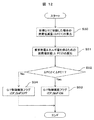
≪要求放電エネルギ算出部≫図11は、図3の要求放電エネルギ算出部26で実行される演算処理の制御フローを示している。
[ステップS20]ステップS20においては、目標ガス燃料比G/Fに対応する放電エネルギ補正値を決定する。これは、図5に示したような放電エネルギ比マップから得られた放電エネルギ比を利用して求めることができる。つまり、運転状態に対応して定められた放電エネルギ比マップから、目標ガス燃料比G/Fに対応した放電エネルギ比を求めればよく、この放電エネルギ比で基本放電エネルギ量を補正して、要求放電エネルギ量を求めるものである。
尚、目標ガス燃料比G/Fの代わりに、図6に示す目標有効ガス燃料比G/Fに対応する放電エネルギ比マップを使用することも可能である。これについては図17で説明する。また、図7~図9に示すような外的な環境要因である湿度、冷却水温度、吸気温度についても同様である。目標ガス燃料比G/Fに対応する放電エネルギ比が求まるとステップS21に移行する。
[ステップS21]ステップS21においては、湿度センサで検出した新気ガスの湿度に対応する放電エネルギ補正値を決定する。これは、図7に示したような放電エネルギ比マップから得られた放電エネルギ比を利用して求めることができる。ここでは、目標ガス燃料比G/F毎の湿度に対応する放電エネルギ比から補正値を求めている。尚、マップの記憶容量を低減する場合は、複数のガス燃料比G/F毎のデータ間を補間することで、目標ガス燃料比G/F毎の間の補正値を求めることができる。湿度に対応する放電エネルギ比が求まるとステップS22に移行する。
[ステップS22]ステップS22においては、冷却水温度に対応する放電エネルギ補正値を決定する。これは、図8に示したような放電エネルギ比マップから得られた放電エネルギ比を利用して求めることができる。ここでも、目標ガス燃料比G/F毎の冷却水温度に対応する放電エネルギ比から補正値を求めている。また、ステップS21の説明にあるように、マップの記憶容量を低減する場合は、複数のガス燃料比G/F毎のデータ間を補間することで、目標ガス燃料比G/F毎の間の補正値を求めることができる。冷却水温に対応する放電エネルギ比が求まるとステップS23に移行する。
[ステップS23]ステップS23においては、吸気温度温に対応する放電エネルギ補正値を決定する。これは、図9に示したような放電エネルギ比マップから得られた放電エネルギ比を利用して求めることができる。ここでは、目標ガス燃料比G/F毎の吸気温度に対応する放電エネルギ比から補正値を求めている。同様に、ステップS21の説明にあるように、マップの記憶容量を低減する場合は、複数のガス燃料比G/F毎のデータ間を補間することで、目標ガス燃料比G/F毎の間の補正値を求めることができる。冷却水温に対応する放電エネルギ比が求まるとステップS24に移行する。
[ステップS24]ステップS24においては、ステップS20~S23で求めた夫々の補正値から要求放電エネルギ量(DCER)を決定する。ここで、ステップS20~S23では補正値が放電エネルギ比で与えられているので、基本放電エネルギ量と、これらの補正値を加算した総補正値の積で、要求放電エネルギ量(DCER)が求められている。尚、放電エネルギ比の代わりに、放電エネルギ比を求める夫々の放電エネルギ量の差分とした補正量の場合は、基本要求エネルギ量と、これらの補正量を加算した総補正量を加算して、要求放電エネルギ量(DCER)を求めることができる。
このように、放電後の火炎核の形成に影響を与える外乱を考慮して要求放電エネルギ量を求めることができる。したがって、様々な条件で変化する目標ガス燃料比G/Fの状態であっても、安定燃焼を実現できる要求放電エネルギの設定ができるため、放電後の火炎核の形成の失敗による失火等の発生を抑制することができるようになる。
この制御フローで求められた要求放電エネルギ量は、次段のエネルギ得失算出部27、及び最終放電エネルギ算出部28に送られる。
≪エネルギ得失算出部≫図12は、図3のエネルギ得失算出部27で実行される演算処理の制御フローを示している。
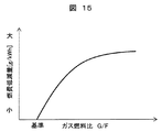
[ステップS30]ステップS30においては、目標ガス燃料比G/Fに制御する場合の燃料低減量ΔFC1を算出する。目標ガス燃料比G/Fに制御する場合の燃料低減量(ΔFC1)は、図15に示すような関係から決めることができる。燃料低減量ΔFC1は運転条件や内燃機関の特性にも依存するが、目標ガス燃料比G/Fを増加(希薄方向)させることで燃料低減量は増加し、所定の目標ガス燃料比G/Fをこえると飽和する傾向にある。
目標ガス燃料比G/Fに制御する時の1時間当たりの燃料低減量(FR)[g/kWh]から、単位時間(1秒)当りの削減可能な燃料低減量(ΔFC1)[g/s]は、内燃機関の出力(We)[W]とした時、以下の(2)式で与えられる。
ΔFC1=FR×We/3600……(2)ここで、求められた燃料低減量Δ(FC1)は、目標ガス燃料比G/Fから決まる燃料低減量となる。燃料低減量(ΔFC1)が求まると次のステップS31に移行する
[ステップS31]次にステップS31においては、要求放電エネルギ量を得るために必要な燃料増加量(ΔFC2)を算出する。機械効率を例えば、投入エネルギ量に対する点火のための放電エネルギ量の転換効率(コイル効率)ηco、内燃機関の熱効率ηi、ベルト伝達効率ηt、オルタネータ発電効率ηa、バッテリ充電効率ηc、バッテリからの供給効率ηsとしたとき、要求放電エネルギ量DCER[J]を得るために一燃焼サイクル当りで必要とされるエネルギ消費量Qc[J]は、1回の放電当り以下の(3)式で与えられる。
Qc=DCER ×ηs×ηc×ηa×ηt×ηi……(3)今、ガソリンの発熱量qg[J/g]とすると、内燃機関の回転数Ne[rpm]とした場合、一気筒の放電によって、1秒間に消費される燃料増加量Δ(FC2)[g/s]は、以下の(4)式で与えられる。
ΔFC2={Ne×(Qc/qg)}/120……(4)ここで、求められた燃料増加量Δ(FC2)は、上述した機械的効率から決まる機械的エネルギ消費量に対応する燃料増加量となる。燃料増加量(ΔFC2)が求まると次のステップS32に移行する。
[ステップS32]ステップS32においては、ステップS30求めた燃料低減量(ΔFC1)と、ステップS31求めた燃料増加量(ΔFC2)の大小関係を比較する。そして、燃料低減量(ΔFC1)が燃料増加量(ΔFC2)に比べて大きい場合は、ステップ33に移行する。一方、燃料増加量(ΔFC2)が燃料低減量(ΔFC1)に比べて大きい場合は、ステップS34に移行する。
このような判断を行なうのは、燃料低減量(ΔFC1)が大きいと目標ガス燃料比G/Fを大きくして燃費を向上することができ、燃料増加量(ΔFC2)が大きいと放電エネルギ量を小さくし、これに合せて目標ガス燃料比G/Fも小さくして混合気を濃くし、失火を避けるようにするためである。これについては後述する。
[ステップS33、S34]そして、上述の判断結果にしたがって、ステップS33においては、目標ガス燃料比G/F制御実施フラグ(CF_GbF)を「ON」に設定し、ステップS34では、目標ガス燃料比G/F制御実施フラグ(CF_GbF)を「OFF」に設定する。
以上の制御フローを実行することで、目標ガス燃料比G/Fに制御した場合の燃料低減量と、要求放電エネルギ量を得るために必要な燃料増加量を比較して、目標ガス燃料比G/Fで内燃機関を動作させた場合に、総合的な燃費低減が実現できるか否か判断することができる。
これによって、最終的に目標ガス燃料比G/Fで内燃機関を動作するように移行することができる。このように、総合的に燃費低減が実現できるときだけ、目標ガス燃料比G/Fを大きくした制御を実施することができ、燃費性能の向上を図ることができるようになる。この制御フローで求められた得失結果は、次段の最終放電エネル算出部28に送られる。
≪最終放電エネルギ算出部≫図13は、図3の最終放電エネルギ算出部28で実行される演算処理の制御フローを示している。
[ステップS40]ステップS40においては、新気ガスの吸気温度、湿度等に基づいて基本放電エネルギ算出部25で求められた基本放電エネルギ量を補正して補正基本放電エネルギ量(MFDE)を決定する。この補正基本放電エネルギ量(MFDE)は、目標ガス燃料比G/Fに切り替えない場合の放電エネルギ量である。したがってこの補正演算では目標ガス燃料比G/Fによる補正は行わないものである。この補正基本放電エネルギ量(MFDE)が求まると、ステップS41に移行する。
[ステップS41]ステップS41においては、ステップS40で求めた補正基本放電エネルギ量(MFDE)と、図11のステップS24で求めた要求放電エネルギ量(DCER)に基づき、点火コイルへのエネルギ投入量を決定する。この制御ステップS41の詳細は、図14に示している制御フローで説明する。ステップS41の演算が終了するとステップS42に移行する。
[ステップS42]ステップS42においては、エネルギ損失算出部27で求めた目標ガス燃料比G/F制御実施フラグ(CF_GbF)が、「ON」か、或いは「OFF」かの判断を実行する。目標ガス燃料比G/F制御実施フラグ(CF_GbF)が「ON」の場合は、ステップS43に移行し、ガス燃料比G/F制御実施フラグ(CF_GbF)が「OFF」の場合は、ステップS44に移行する。
[ステップS43]目標ガス燃料比G/F制御実施フラグ(CF_GbF)が「ON」の場合は、目標ガス燃料比G/Fへの変更を行なうように設定する。これによって、混合気が希薄状態に制御されて燃費が向上されるようになる。
[ステップS44]一方、目標ガス燃料比G/F制御実施フラグ(CF_GbF)が「OFF」の場合は、目標ガス燃料比G/Fへの変更を実行しないので、ステップS44においては、目標ガス燃料比G/Fを標準ガス燃料比G/F、例えば、理論空燃比に設定する。したがって、放電エネルギ量を低減しても着火できる環境とすることができる。
次に、ステップS41で実行される点火コイルへの放電エネルギ量の決定方法について、図14を用いて詳細に説明する。
[ステップS50]ステップS50においては、目標ガス燃料比G/F制御実施フラグ(CF_GbF)がONかOFFかを判断する。OFFの場合はステップS55に移行し、ONの場合は、ステップS51に移行する。
[ステップS51]ステップS51では、回転数に基づく放電期間(DCDR)の演算を実行する。定性的には回転数が高い場合は、ピストンの移動速度に合わせて気筒内の混合気の流動が強化されることで、放電中の再放電が生じて実質的な放電期間が短くなることや、点火に適切なピストン位置にピストンが存在する期間が回転数の増加と共に短くなることを考慮して、放電エネルギを供給する期間を決めている。
定性的には、放電期間を回転数に応じて短くするように設定すれば良く、例えば、内燃機関の回転数1000rpmにおける基準放電時間Tref[sec]をECU20のROM23bに記憶し、これを基準にして演算の対象となる回転数Neから以下の(5)式ように演算して放電期間(DCDR)を求めることができる。
DCDR=(Tref×1000)/Ne……(5)放電期間(DCDR)が求まるとステップS52に移行する。
DCDR=(Tref×1000)/Ne……(5)放電期間(DCDR)が求まるとステップS52に移行する。
[ステップS52]
ステップS52においては、搭載されている点火コイル16を用いて、放電期間(DCDR)と同じ期間内に、発生することができる最大放電エネルギ量(DCEM)を演算する。これは、搭載されている点火コイル16の設計仕様から求めることができる。最大放電エネルギ量(DCEM)が求まるとステップS53に移行する。
ステップS52においては、搭載されている点火コイル16を用いて、放電期間(DCDR)と同じ期間内に、発生することができる最大放電エネルギ量(DCEM)を演算する。これは、搭載されている点火コイル16の設計仕様から求めることができる。最大放電エネルギ量(DCEM)が求まるとステップS53に移行する。
[ステップS53]ステップS53においては、ステップS52で求めた最大放電エネルギ量(DCEM)と、図11のステップS24で求めた要求放電エネルギ量(DCER)とを比較する。この制御ステップで、最大放電エネルギ量(DCEM)が大きいと判断されるとステップS56に移行し、要求放電エネルギ量(DCER)が大きいと判断されるとステップS54に移行する。
[ステップS54]ステップS53での判定で、要求放電エネルギ量(DCER)が大きい場合は、要求放電エネルギ量による放電が実現できないことを示している。したがって、ステップS54では、目標ガス燃料比G/F制御実施フラグ(CF_GbF)をOFFに設定し直すようにしている。目標ガス燃料比G/F制御実施フラグ(CF_GbF)をOFFにするとステップS55に移行する。
[ステップS55]ステップS55においては、ステップS50、及びステップS54で目標ガス燃料比G/F制御実施フラグ(CF_GbF)がOFFとされているので、図13のステップS40で求めた補正基本放電エネルギ量(MFDE)を、最終放電エネルギ量として設定する。
この最終放電エネルギ量(=補正基本放電エネルギ量)は、図13のステップS43で説明したように標準ガス燃料比G/Fに対応したものである。したがって、混合気の濃度が標準ガス燃料比G/Fに設定されているので、最終放電エネルギ量が小さくても着火することが可能である。この結果、失火が発生する可能性がある過大なガス燃料比G/Fにおける動作を避けることができる。補正基本放電エネルギ量(MFDE)が設定されるとステップS57に移行する。
この最終放電エネルギ量(=補正基本放電エネルギ量)は、図13のステップS43で説明したように標準ガス燃料比G/Fに対応したものである。したがって、混合気の濃度が標準ガス燃料比G/Fに設定されているので、最終放電エネルギ量が小さくても着火することが可能である。この結果、失火が発生する可能性がある過大なガス燃料比G/Fにおける動作を避けることができる。補正基本放電エネルギ量(MFDE)が設定されるとステップS57に移行する。
[ステップS56]ステップS53で、要求放電エネルギ量(DCER)より最大放電エネルギ量(DCEM)が大きいと判断されると、要求放電エネルギ量(DCER)で放電することが可能と見做して、判断ステップS56では、要求放電エネルギ量(DCER)を、最終放電エネルギ量として設定する。最終放電エネルギ量が設定されるステップS57に移行する。
[ステップS57]ステップS57においては、点火プラグでの放電後の放電エネルギの追加供給が必要か否かの判断するための放電可能エネルギ量(DENO)を演算する。本制御テップでは、放電開始後の追加電流無しで、放電期間(DCDR)の間に放電可能な放電可能エネルギ量(DENO)を演算する。放電可能エネルギ量(DENO)は、点火コイルの設計仕様と、放電前の1次コイルに流す電流量及び放電期間(DCDR)から求めることができる。
放電可能エネルギ量(DENO)の演算が完了するとステップS58に移行する。
放電可能エネルギ量(DENO)の演算が完了するとステップS58に移行する。
尚、このような放電エネルギの追加ができる点火コイルの例を図16に示している。通常の点火コイルは、放電前に1次側コイルに通電して電気エネルギを充填し、点火制御装置によって1次側コイルに流れる電流を遮断する。この結果、コイルを通過する磁束が変化し、2次側コイルに高い電圧が生じ、点火プラグ17のプラグギャップに放電が生じるものである。
一方、図16に示す点火コイルは、1次側コイルが第1コイル16PAと、付加コイルである第2コイル16PBの2つのコイルで構成されており、例えば第1コイル16PAと第2コイル16PBの電流を遮断した後に、第2コイル16PBに形成される磁束を増加させるように追加電流を流すことで、2次側コイル16Sに流れる電流を第2コイル16PBに追加電流を流さない場合に比べて、増加させることができる。
[ステップS58]ステップS57で放電可能エネルギ量(DENO)が求まると、ステップS58では、追加電流無しで放電可能な放電可能エネルギ量(DENO)と、最終放電エネルギ量である要求放電エネルギ量(DCER)を比較する。要求放電エネルギ(DCER)の方が大きい場合は、ステップS59に移行し、放電エネルギ(DENO)の方が大きい場合は、ステップS61に移行する。
[ステップS59]ステップS59においては、点火コイルの2次側に発生させる目標電流値を決定する。ここでは、定常状態で想定される2次側の放電電圧Vgと要求放電エネルギ量(DCER)、及び放電期間(DCDR)から、目標電流値(Itar)を以下の(6)式の演算で決めることができる。
Itar=DCER/(DCDR×Vg)……(6)目標電流値(Itar)が求まるとステップS60に移行する。
Itar=DCER/(DCDR×Vg)……(6)目標電流値(Itar)が求まるとステップS60に移行する。
[ステップS60]ステップS60においては、ステップS59で求めた目標電流値(Itar)を放電期間(DCDR)、またはこれ以上の期間に流せるように、図16に示すような1次側コイル16の第2コイル16PBの通電時間と追加電流パターン(時間変化)を決定する。この第2コイル16PBの通電時間と追加電流パターン(時間変化)が決定されるとエンドに抜けてこの制御フローを終了するものである。このように、本制御ステップでは、放電エネルギが回転数と正の相関を持つように追加電流の電流量を制御している。
[ステップS61、S62]ステップS58で要求放電エネルギ量(DCER)が追加電流無しで放電可能な放電エネルギ量(DEN0)よりも小さいと判断されているので、ステップS61においては、追加電流無しで最終放電エネルギ量を得るため、放電前の1次コイルへの通電時間を演算する。放電前の電流通電時間の増加に応じて放電エネルギ量は増加する関係にあり、またこの関係はコイルの特性として実験的に決定ができ、かつ、これらの関係はECU20に予め保存することができる。その後、ステップS62に進み、通電後に1次コイル側に通電する電流量を「0」とする。
尚、ステップS55で求めた最終放電エネルギ量としての補正基本放電エネルギ量(MFDE)もステップS61と同じ手法で通電時間を算出されるものである。
≪放電エネルギ制御部、G/F制御部≫
図13に示す制御フロー(=最終放電エネルギ算出部28)で求められた、目標ガス燃料比G/Fの情報はG/F制御部30に与えられ、インジェクタ13からの燃料噴射量を制御して目標ガス燃料比G/Fが得られるようにする。同様に、最終放電エネルギ量の情報は放電エネルギ制御部に与えられ、点火コイルの一次側に流れる一次電流の通流時間や点火時期を制御する。
図13に示す制御フロー(=最終放電エネルギ算出部28)で求められた、目標ガス燃料比G/Fの情報はG/F制御部30に与えられ、インジェクタ13からの燃料噴射量を制御して目標ガス燃料比G/Fが得られるようにする。同様に、最終放電エネルギ量の情報は放電エネルギ制御部に与えられ、点火コイルの一次側に流れる一次電流の通流時間や点火時期を制御する。
以上のような制御プロセスを実行することで、内燃機関の回転数で変化する気筒内混合気の流動の影響を考慮して適切な放電期間を設定でき、また1次側コイルの一部に放電後に追加電流を通電することで、2次側コイルに発生させる電流量を適切に制御することができる。これによって、無駄な通電状態が是正されて、点火コイルの昇温による悪影響や、大電流が流れることによる点火プラグの消耗を抑制することができる防ぐことが出来る。
次に本発明の第2の実施形態を説明するが、第1の実施形態と異なっている点は、パラメータを目標ガス燃料比G/Fに対して、目標有効ガス燃料比G/Fに置き換えたことである。したがって、要求放電エネルギ算出部26で実行される図11に示す制御フロー、及びエネルギ得失算出部27実行される図12に示す制御フローが異なっているものであり、これ以外は第1の実施形態と同様である。以下、夫々の算出部の詳細について説明する。
≪要求放電エネルギ算出部26≫図17には、図3の要求放電エネルギ算出部26で実行される第2の制御フローを示している。
[ステップS70]ステップS70においては、目標ガス燃料比G/F、及び湿度から目標有効ガス燃料比G/Fを決定する。これは、湿度センサ3によって検出した湿度も含めてガス量として見做し、目標ガス燃料比G/Fを達成した場合に気筒内に形成されるガス燃料比G/Fを評価し直して目標有効ガス燃料比G/Fとしたものである。
目標有効ガス燃料比G/Fを「GbFeff」とし、目標空燃比A/Fを「AbFtar」とし、目標EGR率を「EGRtar」、EGRに関する補正係数を「α」、絶対湿度を「AH」、湿度に関する補正係数を「β」とすると、目標有効ガス燃料比G/Fは次の(7)式で計算できる。
GbFeff=AbFtar(1+αEGRtar/(1-EGRtar)+βAH)……(7)そして、目標有効ガス燃料比G/Fが求まるとステップS71に移行する。
GbFeff=AbFtar(1+αEGRtar/(1-EGRtar)+βAH)……(7)そして、目標有効ガス燃料比G/Fが求まるとステップS71に移行する。
[ステップS71]
ステップS71においては、目標有効ガス燃料比G/Fに対応する放電エネルギ補正値を決定する。これは、先に図6に示したような放電エネルギ比マップから得られた放電エネルギ比を利用して求めることができる。つまり、運転状態に対応して定められた放電エネルギ比マップから、目標有効ガス燃料比G/Fに対応した放電エネルギ比を求めればよく、この放電エネルギ比で基本放電エネルギ量を補正して、要求放電エネルギ量を求めるものである。放電エネルギ補正値が求まると次のステップに移行する。
ステップS71においては、目標有効ガス燃料比G/Fに対応する放電エネルギ補正値を決定する。これは、先に図6に示したような放電エネルギ比マップから得られた放電エネルギ比を利用して求めることができる。つまり、運転状態に対応して定められた放電エネルギ比マップから、目標有効ガス燃料比G/Fに対応した放電エネルギ比を求めればよく、この放電エネルギ比で基本放電エネルギ量を補正して、要求放電エネルギ量を求めるものである。放電エネルギ補正値が求まると次のステップに移行する。
[ステップS72]、[ステップS73]、[ステップS74]ステップS72は図11のステップS22に対応し、ステップS73は図11のステップS23に対応し、ステップS74は図11のステップS24に対応しているので、説明は省略する。
このように目標有効ガス燃料比G/Fを設定し、これに対応した放電エネルギ比を求めることで、目標ガス燃料比G/Fと湿度とに分けて設定していた放電エネルギ比マップを一つの放電エネルギ比マップに統合することができるため、ECU20のROM26dのメモリ容量を削減することができる。
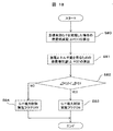
≪エネルギ得失算出部27≫図18には、図3のエネルギ得失算出部27で実行される第2の制御フローを示している。
[ステップS80]ステップS80においては、目標有効ガス燃料比G/Fに制御する場合の燃料低減量ΔFC1を算出する。目標有効ガス燃料比G/Fに制御する場合の燃料低減量(ΔFC1)は、図15に示すような関係から決めることができる。燃料低減量ΔFC1は運転条件や内燃機関の特性にも依存するが、目標有効ガス燃料比G/Fを増加(希薄方向)させることで燃料低減量は増加し、所定の目標有効ガス燃料比G/Fをこえると飽和する傾向にある。
目標有効ガス燃料比G/Fに制御する時の1時間当たりの燃料低減量(FRE)[g/kWh]から、単位時間(1秒)当りに削減可能な燃料低減量(ΔFC1)[g/s]は、内燃機関の出力(We)[W]とした時、以下の(8)式で与えられる。
ΔFC1=FRE×We/3600……(8)燃料低減量(ΔFC1)が求まると次のステップに移行する。
ΔFC1=FRE×We/3600……(8)燃料低減量(ΔFC1)が求まると次のステップに移行する。
[ステップS81]、[ステップS82]、[ステップS83]、[ステップS84]ステップS81は図12のステップS31に対応し、ステップS82は図12のステップS32に対応し、ステップS83は図12のステップS33に対応し、ステップS84は図12のステップS34に対応しているので、説明は省略する。
このように、第1の実施形態の作用、効果に加えて、内燃機関の燃料低減量の演算に目標有効ガス燃料比G/Fを用いることで、第1の実施形態に比べてマップデータ等の低減を図ることができるようになる。
以上の通り、本発明の第1の特徴によれば、点火プラグに放電火花を発生させるための放電電圧を誘起する点火コイルと、点火コイルに放電電圧を発生させる放電電圧発生部と、放電電圧発生部で発生させる基本放電エネルギ量を内燃機関の運転条件に応じて定める基本放電エネルギ算出手段を有する点火制御手段を備え、点火制御手段は、内燃機関の気筒内の混合気を目標ガス燃料比G/Fに制御するのに必要となる放電エネルギ量を、外的な環境要因によって定まる気筒内の混合気の状態に対応して、基本放電エネルギ算出手段で求められた基本放電エネルギ量を補正して求める放電エネルギ補正手段を備える、構成とした。
これによれば、外的な環境要因(外乱)を考慮した上で、目標とするガス燃料比G/Fに制御するために必要となる放電エネルギ量を正確に求めることができる。
また、本発明の第2の特徴によれば、点火プラグに放電火花を発生させるための放電電圧を誘起する点火コイルと、点火コイルに放電電圧を発生させる放電電圧発生部と、放電電圧発生部で発生させる基本放電エネルギ量を内燃機関の運転条件に応じて定める基本放電エネルギ算出手段を有する点火制御手段を備え、点火制御手段は、内燃機関の気筒内の混合気を目標ガス燃料比G/Fに制御することで得られる燃料低減量が、点火プラグでの放電を行なうために必要となる電力のために消費される燃料消費量を上回る場合は、基本放電エネルギ算出手段で求めた基本放電エネルギ量を増加補正する放電エネルギ補正手段を備える、構成とした。
これによれば、希釈燃焼による燃料低減量が点火プラグの放電を行なうために必要となる放電エネルギを得るために増加する燃料消費量を上回る場合に、放電エネルギ量を増加するので、希釈された混合気の燃焼を安定化させることができ、また、燃費性能を向上できるものである。
尚、本発明は上記した実施例に限定されるものではなく、様々な変形例が含まれる。例えば、上記した実施例は本発明を分かりやすく説明するために詳細に説明したものであり、必ずしも説明した全ての構成を備えるものに限定されるものではない。また、ある実施例の構成の一部を他の実施例の構成に置き換えることが可能であり、また、ある実施例の構成に他の実施例の構成を加えることも可能である。また、各実施例の構成の一部について、他の構成の追加・削除・置換をすることが可能である。
1…エアフローセンサ、2…電子制御スロットル、3…湿度センサ、4…過給機、4a…コンプレッサ、4b…タービン、5…可変バルブ、6…吸気マニホールド、7…インタークーラ、9…空燃比センサ、10…三元触媒、11…ウェイストゲート弁、12…アクセル開度センサ、13…インジェクタ、14…シリンダ、15…排気管、16…点火コイル、17…点火プラグ、18…冷却水温センサ、19…クランク角センサ、20…ECU、21…入力回路、22…入出力ポート、23a…CPU、23b…ROM、23c…RAM、24…点火制御部、25…基本放電エネルギ算出部、26…要求放電エネルギ算出部、27…エネルギ得失算出部、28…最終放電エネルギ算出部、29…放電エネルギ制御部、30…ガス燃料比G/F制御部。
Claims (9)
- 点火プラグに放電火花を発生させるための放電電圧を誘起する点火コイルと、
前記点火コイルに放電電圧を発生させる放電電圧発生部と、
前記放電電圧発生部で発生させる基本放電エネルギ量を内燃機関の運転条件に応じて定める基本放電エネルギ算出手段を有する点火制御手段を備え、
前記点火制御手段は、前記内燃機関の気筒内の混合気を目標ガス燃料比G/Fに制御した時に必要となる放電エネルギ量を、外的な環境要因によって定まる前記気筒内の混合気の状態に対応して、前記基本放電エネルギ算出手段で求められた前記基本放電エネルギ量を補正して求める放電エネルギ補正手段を備えることを特徴とする内燃機関の制御装置。 - 点火プラグに放電火花を発生させるための放電電圧を誘起する点火コイルと、
前記点火コイルに放電電圧を発生させる放電電圧発生部と、
前記放電電圧発生部で発生させる基本放電エネルギ量を内燃機関の運転条件に応じて定める基本放電エネルギ算出手段を有する点火制御手段を備え、
前記点火制御手段は、前記内燃機関の気筒内の混合気を目標ガス燃料比G/Fに制御することで得られる燃料低減量が、前記点火プラグでの放電を行なうために必要となる電力のために消費される燃料消費量を上回る場合は、前記基本放電エネルギ算出手段で求めた前記基本放電エネルギ量を増加補正する放電エネルギ補正手段を備えることを特徴とする内燃機関の制御装置。 - 点火プラグに放電火花を発生させるための放電電圧を誘起する点火コイルと、
前記点火コイルに放電電圧を発生させる放電電圧発生部と、
前記放電電圧発生部で発生させる基本放電エネルギ量を内燃機関の運転条件に応じて定める基本放電エネルギ算出手段を有する点火制御手段を備え、
前記点火制御手段は、前記内燃機関の気筒内の混合気を目標ガス燃料比G/Fに制御した時に必要となる最終放電エネルギ量を、外的な環境要因によって定まる前記気筒内の混合気の状態に対応して、前記基本放電エネルギ算出手段で求められた前記基本放電エネルギ量を補正して求めると共に、前記気筒内の混合気を目標ガス燃料比G/Fに制御することで得られる燃料低減量が、前記点火プラグでの放電を行なうために必要となる電力のために消費される燃料消費量を上回る場合は、補正された前記基本放電エネルギ量を増加補正して前記最終放電エネルギ量とする放電エネルギ補正手段を備えることを特徴とする内燃機関の制御装置。 - 請求項1或いは請求項3に記載の内燃機関の制御装置において、
前記基本放電エネルギ算出手段は、前記内燃機関の回転数と要求トルクから前記基本放電エネルギ量を求めると共に、
前記放電エネルギ補正手段は少なくとも前記外的な環境要因として前記目標ガス燃料比G/Fに基づいて前記基本放電エネルギ量を補正することを特徴とする内燃機関の制御装置。 - 請求項4に記載の内燃機関の制御装置において、
前記放電エネルギ補正手段は、前記基本放電エネルギ量を、前記目標ガス燃料比G/Fに加えて、前記外的な環境要因として新気ガスの湿度、吸気温度、前記内燃機関の冷却水の少なくとも1つ以上に基づいて補正することを特徴とする内燃機関の制御装置。 - 請求項3に記載の内燃機関の制御装置において、
前記放電エネルギ補正手段によって前記基本放電エネルギ量が増加補正された場合、前記気筒内の混合気を量論混合比よりも希薄側の前記目標ガス燃料比G/Fに制御するガス燃料比制御手段を備えていることを特徴とする内燃機関の制御装置。 - 請求項2或いは請求項3に記載の内燃機関の制御装置において、
前記放電エネルギ補正手段によって、補正された前記基本放電エネルギ量が増加補正されない場合、前記気筒内の混合気を量論混合比に制御するガス燃料比制御手段を備えている
ことを特徴とする内燃機関の制御装置。 - 請求項6に記載の内燃機関の制御装置において、
前記点火コイルの1次コイルには、2次コイルに放電電圧が発生した後に、前記2次コイルに発生する放電電流を増加させる追加電流が流される付加コイルが設けられており、
前記放電エネルギ補正手段は、前記内燃機関の回転数から定まる放電期間の間に追加電流を流さない場合の放電可能エネルギ量を求めると共に、前記最終放電エネルギ量が前記放電可能エネルギ量を超えない場合は、前記付加コイルに追加電流を流す制御を実行することを特徴とする内燃機関の制御装置。 - 請求項1乃至請求項7のいずれか1つに記載の内燃機関の制御装置において、
前記目標ガス燃料比G/Fは、前記気筒内に吸入される空気及び排気ガス及び湿度を含む新気ガスと燃料から決められていることを特徴とする内燃機関の制御装置。
Applications Claiming Priority (2)
| Application Number | Priority Date | Filing Date | Title |
|---|---|---|---|
| JP2017004851A JP6749255B2 (ja) | 2017-01-16 | 2017-01-16 | 内燃機関の制御装置 |
| JP2017-004851 | 2017-01-16 |
Publications (1)
| Publication Number | Publication Date |
|---|---|
| WO2018131407A1 true WO2018131407A1 (ja) | 2018-07-19 |
Family
ID=62840372
Family Applications (1)
| Application Number | Title | Priority Date | Filing Date |
|---|---|---|---|
| PCT/JP2017/045672 Ceased WO2018131407A1 (ja) | 2017-01-16 | 2017-12-20 | 内燃機関の制御装置 |
Country Status (2)
| Country | Link |
|---|---|
| JP (1) | JP6749255B2 (ja) |
| WO (1) | WO2018131407A1 (ja) |
Cited By (3)
| Publication number | Priority date | Publication date | Assignee | Title |
|---|---|---|---|---|
| WO2020235219A1 (ja) * | 2019-05-23 | 2020-11-26 | 日立オートモティブシステムズ株式会社 | 内燃機関用制御装置 |
| JPWO2020262098A1 (ja) * | 2019-06-26 | 2020-12-30 | ||
| DE102020216494B4 (de) | 2019-12-23 | 2026-07-30 | Lg Electronics Inc. | Verfahren zum Steuern eines Gaswärmepumpensystems |
Citations (3)
| Publication number | Priority date | Publication date | Assignee | Title |
|---|---|---|---|---|
| JP2000291519A (ja) * | 1999-04-07 | 2000-10-17 | Nissan Motor Co Ltd | 内燃機関の点火装置 |
| JP2016011606A (ja) * | 2014-06-27 | 2016-01-21 | ダイハツ工業株式会社 | 内燃機関の制御装置 |
| JP2016037880A (ja) * | 2014-08-06 | 2016-03-22 | スズキ株式会社 | 点火制御装置 |
-
2017
- 2017-01-16 JP JP2017004851A patent/JP6749255B2/ja active Active
- 2017-12-20 WO PCT/JP2017/045672 patent/WO2018131407A1/ja not_active Ceased
Patent Citations (3)
| Publication number | Priority date | Publication date | Assignee | Title |
|---|---|---|---|---|
| JP2000291519A (ja) * | 1999-04-07 | 2000-10-17 | Nissan Motor Co Ltd | 内燃機関の点火装置 |
| JP2016011606A (ja) * | 2014-06-27 | 2016-01-21 | ダイハツ工業株式会社 | 内燃機関の制御装置 |
| JP2016037880A (ja) * | 2014-08-06 | 2016-03-22 | スズキ株式会社 | 点火制御装置 |
Cited By (11)
| Publication number | Priority date | Publication date | Assignee | Title |
|---|---|---|---|---|
| WO2020235219A1 (ja) * | 2019-05-23 | 2020-11-26 | 日立オートモティブシステムズ株式会社 | 内燃機関用制御装置 |
| JPWO2020235219A1 (ja) * | 2019-05-23 | 2020-11-26 | ||
| JP7130868B2 (ja) | 2019-05-23 | 2022-09-05 | 日立Astemo株式会社 | 内燃機関用制御装置 |
| US11802534B2 (en) | 2019-05-23 | 2023-10-31 | Hitachi Astemo, Ltd. | Control device for internal combustion engine |
| JPWO2020262098A1 (ja) * | 2019-06-26 | 2020-12-30 | ||
| WO2020262098A1 (ja) * | 2019-06-26 | 2020-12-30 | 日立オートモティブシステムズ株式会社 | 内燃機関用制御装置 |
| JP7270040B2 (ja) | 2019-06-26 | 2023-05-09 | 日立Astemo株式会社 | 内燃機関用制御装置 |
| JP2023083550A (ja) * | 2019-06-26 | 2023-06-15 | 日立Astemo株式会社 | 内燃機関用制御装置 |
| JP7497489B2 (ja) | 2019-06-26 | 2024-06-10 | 日立Astemo株式会社 | 内燃機関用制御装置 |
| US12292023B2 (en) | 2019-06-26 | 2025-05-06 | Hitachi Astemo, Ltd. | Control device for internal combustion engine |
| DE102020216494B4 (de) | 2019-12-23 | 2026-07-30 | Lg Electronics Inc. | Verfahren zum Steuern eines Gaswärmepumpensystems |
Also Published As
| Publication number | Publication date |
|---|---|
| JP6749255B2 (ja) | 2020-09-02 |
| JP2018115556A (ja) | 2018-07-26 |
Similar Documents
| Publication | Publication Date | Title |
|---|---|---|
| JP3680491B2 (ja) | 内燃機関の制御装置 | |
| JP3743607B2 (ja) | 内燃機関の制御装置 | |
| JP4243598B2 (ja) | 内燃機関の制御装置 | |
| JP4447626B2 (ja) | 内燃機関の制御装置 | |
| JP6280537B2 (ja) | 内燃機関の制御装置 | |
| CN103380281B (zh) | 用于内燃机的控制器和控制方法 | |
| JP2000291519A (ja) | 内燃機関の点火装置 | |
| WO2020145105A1 (ja) | 制御装置 | |
| JP2007064157A (ja) | 内燃機関の制御装置 | |
| US20150369152A1 (en) | Control Device and Control Method of Engine | |
| JP6749255B2 (ja) | 内燃機関の制御装置 | |
| JP3654010B2 (ja) | 内燃機関の制御装置 | |
| JP5373687B2 (ja) | バイフューエルエンジンのアイドル回転速度制御装置 | |
| JP4806998B2 (ja) | 内燃機関 | |
| JP4859731B2 (ja) | 内燃機関の制御装置 | |
| JP2009013952A (ja) | 内燃機関の制御装置 | |
| JP5075041B2 (ja) | 内燃機関の燃料噴射制御装置 | |
| JP5692130B2 (ja) | 内燃機関制御装置 | |
| JP4615501B2 (ja) | 内燃機関の制御装置 | |
| WO2022269976A1 (ja) | 内燃機関の制御装置 | |
| JP4339599B2 (ja) | 筒内噴射式内燃機関の制御装置 | |
| JP2008202461A (ja) | 内燃機関の燃料噴射制御装置 | |
| JP6350974B2 (ja) | エンジンの制御装置 | |
| JP6647983B2 (ja) | 車両の制御装置 | |
| JP2013104317A (ja) | エンジンの制御装置 |
Legal Events
| Date | Code | Title | Description |
|---|---|---|---|
| 121 | Ep: the epo has been informed by wipo that ep was designated in this application |
Ref document number: 17891537 Country of ref document: EP Kind code of ref document: A1 |
|
| NENP | Non-entry into the national phase |
Ref country code: DE |
|
| 122 | Ep: pct application non-entry in european phase |
Ref document number: 17891537 Country of ref document: EP Kind code of ref document: A1 |