WO2018124231A1 - 仕切り部材、組電池及び組電池の熱伝達制御方法 - Google Patents
仕切り部材、組電池及び組電池の熱伝達制御方法 Download PDFInfo
- Publication number
- WO2018124231A1 WO2018124231A1 PCT/JP2017/047090 JP2017047090W WO2018124231A1 WO 2018124231 A1 WO2018124231 A1 WO 2018124231A1 JP 2017047090 W JP2017047090 W JP 2017047090W WO 2018124231 A1 WO2018124231 A1 WO 2018124231A1
- Authority
- WO
- WIPO (PCT)
- Prior art keywords
- partition member
- cell
- unit cell
- thermal resistance
- assembled battery
- Prior art date
- Legal status (The legal status is an assumption and is not a legal conclusion. Google has not performed a legal analysis and makes no representation as to the accuracy of the status listed.)
- Ceased
Links
Images


Classifications
-
- H—ELECTRICITY
- H01—ELECTRIC ELEMENTS
- H01M—PROCESSES OR MEANS, e.g. BATTERIES, FOR THE DIRECT CONVERSION OF CHEMICAL ENERGY INTO ELECTRICAL ENERGY
- H01M10/00—Secondary cells; Manufacture thereof
- H01M10/60—Heating or cooling; Temperature control
- H01M10/61—Types of temperature control
- H01M10/617—Types of temperature control for achieving uniformity or desired distribution of temperature
-
- H—ELECTRICITY
- H01—ELECTRIC ELEMENTS
- H01M—PROCESSES OR MEANS, e.g. BATTERIES, FOR THE DIRECT CONVERSION OF CHEMICAL ENERGY INTO ELECTRICAL ENERGY
- H01M50/00—Constructional details or processes of manufacture of the non-active parts of electrochemical cells other than fuel cells, e.g. hybrid cells
- H01M50/20—Mountings; Secondary casings or frames; Racks, modules or packs; Suspension devices; Shock absorbers; Transport or carrying devices; Holders
- H01M50/289—Mountings; Secondary casings or frames; Racks, modules or packs; Suspension devices; Shock absorbers; Transport or carrying devices; Holders characterised by spacing elements or positioning means within frames, racks or packs
-
- H—ELECTRICITY
- H01—ELECTRIC ELEMENTS
- H01M—PROCESSES OR MEANS, e.g. BATTERIES, FOR THE DIRECT CONVERSION OF CHEMICAL ENERGY INTO ELECTRICAL ENERGY
- H01M10/00—Secondary cells; Manufacture thereof
- H01M10/42—Methods or arrangements for servicing or maintenance of secondary cells or secondary half-cells
-
- H—ELECTRICITY
- H01—ELECTRIC ELEMENTS
- H01M—PROCESSES OR MEANS, e.g. BATTERIES, FOR THE DIRECT CONVERSION OF CHEMICAL ENERGY INTO ELECTRICAL ENERGY
- H01M10/00—Secondary cells; Manufacture thereof
- H01M10/60—Heating or cooling; Temperature control
- H01M10/62—Heating or cooling; Temperature control specially adapted for specific applications
- H01M10/625—Vehicles
-
- H—ELECTRICITY
- H01—ELECTRIC ELEMENTS
- H01M—PROCESSES OR MEANS, e.g. BATTERIES, FOR THE DIRECT CONVERSION OF CHEMICAL ENERGY INTO ELECTRICAL ENERGY
- H01M10/00—Secondary cells; Manufacture thereof
- H01M10/60—Heating or cooling; Temperature control
- H01M10/62—Heating or cooling; Temperature control specially adapted for specific applications
- H01M10/627—Stationary installations, e.g. power plant buffering or backup power supplies
-
- H—ELECTRICITY
- H01—ELECTRIC ELEMENTS
- H01M—PROCESSES OR MEANS, e.g. BATTERIES, FOR THE DIRECT CONVERSION OF CHEMICAL ENERGY INTO ELECTRICAL ENERGY
- H01M10/00—Secondary cells; Manufacture thereof
- H01M10/60—Heating or cooling; Temperature control
- H01M10/64—Heating or cooling; Temperature control characterised by the shape of the cells
- H01M10/647—Prismatic or flat cells, e.g. pouch cells
-
- H—ELECTRICITY
- H01—ELECTRIC ELEMENTS
- H01M—PROCESSES OR MEANS, e.g. BATTERIES, FOR THE DIRECT CONVERSION OF CHEMICAL ENERGY INTO ELECTRICAL ENERGY
- H01M10/00—Secondary cells; Manufacture thereof
- H01M10/60—Heating or cooling; Temperature control
- H01M10/65—Means for temperature control structurally associated with the cells
- H01M10/651—Means for temperature control structurally associated with the cells characterised by parameters specified by a numeric value or mathematical formula, e.g. ratios, sizes or concentrations
-
- H—ELECTRICITY
- H01—ELECTRIC ELEMENTS
- H01M—PROCESSES OR MEANS, e.g. BATTERIES, FOR THE DIRECT CONVERSION OF CHEMICAL ENERGY INTO ELECTRICAL ENERGY
- H01M10/00—Secondary cells; Manufacture thereof
- H01M10/60—Heating or cooling; Temperature control
- H01M10/65—Means for temperature control structurally associated with the cells
- H01M10/653—Means for temperature control structurally associated with the cells characterised by electrically insulating or thermally conductive materials
-
- H—ELECTRICITY
- H01—ELECTRIC ELEMENTS
- H01M—PROCESSES OR MEANS, e.g. BATTERIES, FOR THE DIRECT CONVERSION OF CHEMICAL ENERGY INTO ELECTRICAL ENERGY
- H01M10/00—Secondary cells; Manufacture thereof
- H01M10/60—Heating or cooling; Temperature control
- H01M10/65—Means for temperature control structurally associated with the cells
- H01M10/655—Solid structures for heat exchange or heat conduction
- H01M10/6554—Rods or plates
- H01M10/6555—Rods or plates arranged between the cells
-
- H—ELECTRICITY
- H01—ELECTRIC ELEMENTS
- H01M—PROCESSES OR MEANS, e.g. BATTERIES, FOR THE DIRECT CONVERSION OF CHEMICAL ENERGY INTO ELECTRICAL ENERGY
- H01M10/00—Secondary cells; Manufacture thereof
- H01M10/60—Heating or cooling; Temperature control
- H01M10/65—Means for temperature control structurally associated with the cells
- H01M10/658—Means for temperature control structurally associated with the cells by thermal insulation or shielding
-
- H—ELECTRICITY
- H01—ELECTRIC ELEMENTS
- H01M—PROCESSES OR MEANS, e.g. BATTERIES, FOR THE DIRECT CONVERSION OF CHEMICAL ENERGY INTO ELECTRICAL ENERGY
- H01M50/00—Constructional details or processes of manufacture of the non-active parts of electrochemical cells other than fuel cells, e.g. hybrid cells
- H01M50/20—Mountings; Secondary casings or frames; Racks, modules or packs; Suspension devices; Shock absorbers; Transport or carrying devices; Holders
- H01M50/204—Racks, modules or packs for multiple batteries or multiple cells
-
- H—ELECTRICITY
- H01—ELECTRIC ELEMENTS
- H01M—PROCESSES OR MEANS, e.g. BATTERIES, FOR THE DIRECT CONVERSION OF CHEMICAL ENERGY INTO ELECTRICAL ENERGY
- H01M50/00—Constructional details or processes of manufacture of the non-active parts of electrochemical cells other than fuel cells, e.g. hybrid cells
- H01M50/20—Mountings; Secondary casings or frames; Racks, modules or packs; Suspension devices; Shock absorbers; Transport or carrying devices; Holders
- H01M50/249—Mountings; Secondary casings or frames; Racks, modules or packs; Suspension devices; Shock absorbers; Transport or carrying devices; Holders specially adapted for aircraft or vehicles, e.g. cars or trains
-
- H—ELECTRICITY
- H01—ELECTRIC ELEMENTS
- H01M—PROCESSES OR MEANS, e.g. BATTERIES, FOR THE DIRECT CONVERSION OF CHEMICAL ENERGY INTO ELECTRICAL ENERGY
- H01M50/00—Constructional details or processes of manufacture of the non-active parts of electrochemical cells other than fuel cells, e.g. hybrid cells
- H01M50/20—Mountings; Secondary casings or frames; Racks, modules or packs; Suspension devices; Shock absorbers; Transport or carrying devices; Holders
- H01M50/289—Mountings; Secondary casings or frames; Racks, modules or packs; Suspension devices; Shock absorbers; Transport or carrying devices; Holders characterised by spacing elements or positioning means within frames, racks or packs
- H01M50/291—Mountings; Secondary casings or frames; Racks, modules or packs; Suspension devices; Shock absorbers; Transport or carrying devices; Holders characterised by spacing elements or positioning means within frames, racks or packs characterised by their shape
-
- H—ELECTRICITY
- H01—ELECTRIC ELEMENTS
- H01M—PROCESSES OR MEANS, e.g. BATTERIES, FOR THE DIRECT CONVERSION OF CHEMICAL ENERGY INTO ELECTRICAL ENERGY
- H01M50/00—Constructional details or processes of manufacture of the non-active parts of electrochemical cells other than fuel cells, e.g. hybrid cells
- H01M50/20—Mountings; Secondary casings or frames; Racks, modules or packs; Suspension devices; Shock absorbers; Transport or carrying devices; Holders
- H01M50/289—Mountings; Secondary casings or frames; Racks, modules or packs; Suspension devices; Shock absorbers; Transport or carrying devices; Holders characterised by spacing elements or positioning means within frames, racks or packs
- H01M50/293—Mountings; Secondary casings or frames; Racks, modules or packs; Suspension devices; Shock absorbers; Transport or carrying devices; Holders characterised by spacing elements or positioning means within frames, racks or packs characterised by the material
-
- H—ELECTRICITY
- H01—ELECTRIC ELEMENTS
- H01M—PROCESSES OR MEANS, e.g. BATTERIES, FOR THE DIRECT CONVERSION OF CHEMICAL ENERGY INTO ELECTRICAL ENERGY
- H01M2220/00—Batteries for particular applications
- H01M2220/10—Batteries in stationary systems, e.g. emergency power source in plant
-
- H—ELECTRICITY
- H01—ELECTRIC ELEMENTS
- H01M—PROCESSES OR MEANS, e.g. BATTERIES, FOR THE DIRECT CONVERSION OF CHEMICAL ENERGY INTO ELECTRICAL ENERGY
- H01M2220/00—Batteries for particular applications
- H01M2220/20—Batteries in motive systems, e.g. vehicle, ship, plane
-
- Y—GENERAL TAGGING OF NEW TECHNOLOGICAL DEVELOPMENTS; GENERAL TAGGING OF CROSS-SECTIONAL TECHNOLOGIES SPANNING OVER SEVERAL SECTIONS OF THE IPC; TECHNICAL SUBJECTS COVERED BY FORMER USPC CROSS-REFERENCE ART COLLECTIONS [XRACs] AND DIGESTS
- Y02—TECHNOLOGIES OR APPLICATIONS FOR MITIGATION OR ADAPTATION AGAINST CLIMATE CHANGE
- Y02E—REDUCTION OF GREENHOUSE GAS [GHG] EMISSIONS, RELATED TO ENERGY GENERATION, TRANSMISSION OR DISTRIBUTION
- Y02E60/00—Enabling technologies; Technologies with a potential or indirect contribution to GHG emissions mitigation
- Y02E60/10—Energy storage using batteries
-
- Y—GENERAL TAGGING OF NEW TECHNOLOGICAL DEVELOPMENTS; GENERAL TAGGING OF CROSS-SECTIONAL TECHNOLOGIES SPANNING OVER SEVERAL SECTIONS OF THE IPC; TECHNICAL SUBJECTS COVERED BY FORMER USPC CROSS-REFERENCE ART COLLECTIONS [XRACs] AND DIGESTS
- Y02—TECHNOLOGIES OR APPLICATIONS FOR MITIGATION OR ADAPTATION AGAINST CLIMATE CHANGE
- Y02T—CLIMATE CHANGE MITIGATION TECHNOLOGIES RELATED TO TRANSPORTATION
- Y02T10/00—Road transport of goods or passengers
- Y02T10/60—Other road transportation technologies with climate change mitigation effect
- Y02T10/70—Energy storage systems for electromobility, e.g. batteries
Definitions
- the present invention relates to a partition member, an assembled battery, and a heat transfer control method for the assembled battery.
- the safety of the secondary battery tends to conflict with the energy density, and the safety tends to decrease as the secondary battery has a higher energy density.
- the battery surface temperature when the secondary battery is damaged due to overcharging or internal short circuit exceeds several hundred degrees Celsius, It may be close.
- a secondary battery used for a power source of a vehicle or the like is generally used as an assembled battery composed of a plurality of single cells (hereinafter also referred to as “cells”). When it reaches, the adjacent battery is damaged by the heat generation, and the damage may spread to the whole assembled battery in a chain. In order to prevent such a chain of damage between batteries, various techniques for cooling damaged batteries and techniques for suppressing the transfer of heat from damaged batteries to undamaged batteries have been proposed.
- Patent Document 1 discusses a method of cooling a battery that has abnormally generated heat.
- a cooling unit containing a coolant is provided in the vicinity of the unit cell, the sealing unit includes a sealing part formed by sealing a sheet-like part, and a part of the sealing part Discloses a battery module provided with an opening portion that is opened when a unit cell abnormally generates heat.
- a battery unit composed of a plurality of single cells, a storage part at least one of which is an open end, a housing for storing the battery unit in the storage part, and an opening part
- the housing includes a lid that covers the open end, a heat absorbing material, and an exterior film that contains the heat absorbing material, and a heat absorbing member provided in contact with a side surface of the battery unit
- a battery module is disclosed in which the outer film has a laminated structure of a resin layer and a metal film having a melting point higher than the softening temperature of the resin layer and melted by the heat generated by the unit cell.
- the partition member installed between batteries is comprised with a meltable preform
- a method for suppressing heat transfer to adjacent batteries is disclosed.
- Patent Document 4 a base material formed of a resin as a partition member installed between power storage elements, and a foaming agent that is held by the base material and is thermally decomposed in response to a temperature rise accompanying heat generation of the power storage element, A method for suppressing heat transfer from an abnormally heated battery to an adjacent battery is disclosed.
- Patent Document 1 a detailed examination of a method of cooling a battery that has abnormally generated heat has been made, but no quantitative examination has been made on the amount of heat generated by the abnormally heated cell and the cooling ability of the coolant. Moreover, in the said patent document 2, the quantitative examination about the emitted-heat amount of the battery which carried out abnormal heat generation, and the cooling capacity of a coolant is not made
- An object of the present invention is to provide a partition member, an assembled battery, and an assembled battery control method capable of controlling heat transfer between the single batteries in the assembled battery including a plurality of single batteries.
- the inventors of the present invention paid attention to the thermal resistance value necessary for preventing the chain of damage between the batteries, which has not been sufficiently studied in these prior arts, and conducted a detailed examination of the conditions.
- the average temperature of each of the two surfaces is about the same as the cell temperature in the normal state, or the cell in the abnormal heat generation state.
- the inventors have found that it is important to appropriately control the thermal resistance value depending on whether the temperature is comparable to the temperature, and have reached the present invention.
- the present invention is as follows.
- a partition member that partitions the cells constituting the assembled battery and has two surfaces in the thickness direction, and the unit area in the thickness direction when the average temperature of one of the two surfaces exceeds 180 ° C.
- a partition member satisfying 2. ⁇ 1 ⁇ 5.0 ⁇ 10 ⁇ 3 [m 2 ⁇ K / W] (Formula 1) ⁇ 2 ⁇ 4.0 ⁇ 10 ⁇ 3 [m 2 ⁇ K / W] (Formula 2)
- the thermal conductivity in the thickness direction is 2.0 ⁇ 10 ⁇ 2 W / m ⁇ K or more and 2.0 W / m ⁇ K or less. Yes, and When the average temperature of both surfaces is 80 ° C. or less, the thermal conductivity in the thickness direction is 5.0 ⁇ 10 ⁇ 2 W / m ⁇ K or more and 50 W / m ⁇ K or less.
- a plurality of unit cells including a first unit cell, a second unit cell, and a third unit cell; A first partition member that partitions the first unit cell and the second unit cell; and a second partition member that partitions the second unit cell and the third unit cell;
- the second unit cell deviates from the normal state due to heat from the first unit cell that has reached an abnormal heat generation state, it is transmitted from the first unit cell to the second unit cell via the first partition member.
- the amount of heat is suppressed by the first partition member, and the amount of heat transferred from the first unit cell to the third unit cell holding the normal state is not suppressed by the second partition member. battery.
- a method for controlling heat transfer of a battery pack in which cells are partitioned by a partition member has two surfaces in the thickness direction, one of which is a first surface facing the first unit cell, and the other surface is a second surface facing the second unit cell.
- Surface When the average temperature of the first surface does not exceed 80 ° C., the thermal resistance per unit area in the thickness direction ( ⁇ 2 ) satisfies the following formula 2 and heat from the first unit cell is transferred to the second unit cell.
- the first unit cell reaches an abnormal heat generation state, and the second unit cell deviates from the normal state by heat transmitted from the first unit cell through the partition member, and the heat from the first unit cell causes the
- the thermal resistance per unit area in the thickness direction ( ⁇ 1 ) satisfies the following formula 1 and the heat transmitted from the first unit cell through the partition member: Suppress the amount, A heat transfer control method for an assembled battery.
- heat transfer between the unit cells can be controlled.
- FIG. 6 is a graph showing a temperature change inside a cell in Comparative Example 1. It is a graph which shows transition of the surface average temperature of the partition member in the comparative example 1. 6 is a graph showing a transition of thermal resistance of a partition member in Comparative Example 1. 4 is a graph showing a temperature change inside a cell in Example 1.
- FIG. 3 is a graph showing the transition of the average surface temperature of the partition member in Example 1. It is a graph which shows transition of the thermal resistance of the partition member in Example 1.
- FIG. 6 is a graph showing a temperature change inside a cell in Comparative Example 2. It is a graph which shows transition of the surface average temperature of the partition member in the comparative example 2.
- FIG. It is a graph which shows transition of the thermal resistance of the partition member in the comparative example 2.
- 10 is a graph showing a temperature change inside a cell in Comparative Example 3. It is a graph which shows transition of the surface average temperature of the partition member in the comparative example 3. It is a graph which shows transition of the thermal resistance of the partition member in the comparative example 3.
- 10 is a graph showing a temperature change inside a cell in Comparative Example 4. It is a graph which shows transition of the surface average temperature of the partition member in the comparative example 4. It is a graph which shows transition of the thermal resistance of the partition member in the comparative example 4.
- the partition member which concerns on this invention is a partition member which partitions off between the single cells which comprise an assembled battery.
- This partition member partitions the cells constituting the assembled battery and has two surfaces in the thickness direction, and the unit in the thickness direction when the average temperature of one of the two surfaces exceeds 180 ° C.
- ⁇ 1 5.0 ⁇ 10 ⁇ 3 [m 2 ⁇ K / W] (Formula 1) ⁇ 2 ⁇ 4.0 ⁇ 10 ⁇ 3 [m 2 ⁇ K / W] (Formula 2)
- ⁇ 1 is preferably 1.0 ⁇ 10 ⁇ 2 or more, more preferably 2.0 ⁇ 10 ⁇ 2 or more.
- ⁇ 2 is preferably 2.0 ⁇ 10 ⁇ 3 or less, more preferably 1.0 ⁇ 10 ⁇ 3 or less.
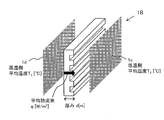
- FIG. 1 is a diagram illustrating a partition member.
- FIG. 1 illustrates a rectangular parallelepiped (plate) partition member 1 (referred to as a partition member 1A in the description of FIG. 1) having vertical, horizontal, and thickness (width).
- the partition member 1A has two surfaces 1a and 1b that face in opposite directions in the thickness direction.
- the partition member 1A is disposed between the single cells in order to partition the single cells constituting the assembled battery.
- each of the surface 1a and the surface 1b is set to face the partition target cell.
- each of the surface 1a and the surface 1b may be in a state where it is in contact with the opposing unit cell or in a state where it is close.
- the surface 1a and the surface 1b can be used as “two surfaces in the thickness direction for partitioning the cells constituting the assembled battery”.
- one of the “two surfaces in the thickness direction partitioning the cells constituting the assembled battery” may not face the cell.
- the thermal resistance ( ⁇ ) per unit area of the partition member means a heat transfer resistance per unit cross-sectional area in the thickness direction of the partition member.
- the thermal resistance ( ⁇ ) per unit area of the partition member is the thermal conductivity (k [W / m ⁇ K]) in the thickness direction of the material used as the partition member and the thickness (d [m]) of the partition member. Can be used.
- the thermal resistance ( ⁇ ) per unit area of the partition member 1A shown in FIG. 1 will be described.
- the partition member 1A is made of a single material and has a constant density.
- the thermal conductivity in the thickness direction of the partition member 1A is k [W / m ⁇ K], and the thickness of the partition member 1A is d [m].
- the average value of the surface temperature of the surface 1b of the partition member 1A is T 1 [° C.]
- the average value of the surface temperature of the surface 1a is T 2 [° C.].
- the heat flow rate (heat flux) q per unit cross-sectional area of the partition member 1A can be expressed by the following equation (1).
- q k (T 1 ⁇ T 2 ) / d [W / m 2 ] (1)
- the heat flux (q) can be expressed by the following equation (2) using the thermal resistance ( ⁇ ) per unit area.
- the shape (structure) of the partition member 1 is not limited to a rectangular parallelepiped. If it is a shape which has a thickness direction, even if it is a case where a partition member has a comb-shaped structure, a hollow structure, a lattice structure, etc., the thermal resistance of the partition member 1 can be represented by said Formula (3).
- the partition member 1 is not limited to being formed of a single material, and may be formed of a combination of a plurality of materials. Even if it is formed by a combination of a plurality of materials, the thermal resistance per unit area of the partition member 1 can be expressed by the above formula (3).
- the combination of materials is, for example, polyethylene, chlorinated polyethylene, ethylene vinyl chloride copolymer, ethylene vinyl acetate copolymer, polyvinyl acetate, polypropylene, polybutene, polybutadiene, polymethylpentene, polystyrene, poly ⁇ -methylstyrene, polyparavinylphenol, ABS resin, SAN resin, AES resin, AAS resin, methacrylic resin, norbornene resin, polyvinyl chloride, acrylic modified polyvinyl chloride, polyvinylidene chloride, polyallylamine, polyvinyl ether, polyvinyl alcohol, ethylene vinyl alcohol copolymer, petroleum resin , Thermoplastic elastomers, thermoplastic polyurethane resins, polyacrylonitrile, polyvinyl butyral, phenolic resins, epoxy resins, urea resins, melamine resins, Resin, unsaturated polyester resin, diallyl phthalate, guanamine,
- FIG. 2 illustrates a partition member 1 having a comb structure (referred to as partition member 1B in the description of FIG. 2).
- the partition member 1B is formed in a plate shape as a whole, and its cross section is formed in a comb shape.
- the partition member 1B also has two surfaces 1c and 1d that face in opposite directions in the thickness direction.
- the surface 1c is a striped uneven surface, and the surface 1d is a flat surface. From this, the cross section which cut
- the surface 1c and the surface 1d can be handled in the same manner as the surface 1a and the surface 1b.
- the method for obtaining the thermal resistance ( ⁇ ) per unit area of the partition member 1B shown in FIG. 2 is as follows.
- the average temperature of each surface of the surface 1c and the surface 1d, can be used as the T 1 and T 2 in the formula (1) and (2).
- the average value of the heat flow rate per unit cross-sectional area of the partition member 1B can be used as the heat flux (q) of the above formulas (1) and (2).
- the thermal conductivity (k) the synthetic thermal conductivity calculated in consideration of the structure and material type of the partition member 1B is used as the thermal conductivity (k) in the above formulas (1) and (3).
- the thermal resistance ( ⁇ ) per unit area can be expressed by the above formula (3).
- the effective thermal resistance per unit area calculated in consideration of the structure and material type of the partition member 1B can be used as the thermal resistance per unit area ( ⁇ ).
- the thermal resistance (R) of the member is obtained.
- the thermal resistance (R) can be expressed by the following equation (4).
- R R 1 + R 2 + R 3 +... + R n (4)
- the composite thermal conductivity of the composite member when n types of materials are arranged in parallel is calculated.
- Expression (5) is transformed using Expression (9) and Expression (3), the following Expression (10) is obtained.
- the partition member is a comb-shaped partition member such as the partition member 1B or a partition member such as a hollow structure or a lattice structure
- the thermal conductivity of air which is the material of the cavity part
- the thickness and cross-sectional area of the cavity part are determined.
- the thickness direction The thermal conductivity is 2.0 ⁇ 10 ⁇ 2 W / m ⁇ K to 2.0 W / m ⁇ K, and the average temperature of the surface (for example, any one of the surfaces 1a to 1d) is 80 ° C.
- the thermal conductivity in the thickness direction is 5.0 ⁇ 10 ⁇ 2 W / m ⁇ K or more and 50 W / m ⁇ K or less.
- the thickness of the unit cell constituting the assembled battery is L [mm]
- the thickness is preferably L / 50 mm or more and L / 10 mm or less.
- the range assumed about the thickness (L) of the unit cell constituting the assembled battery is usually 10 mm ⁇ L ⁇ 100 mm, preferably 15 mm ⁇ L ⁇ 80 mm.
- the temperature of the surface including the first point is increased from 160 ° C. to 300 ° C.
- the thermal resistance ( ⁇ 1 ) is obtained by the above-described method when the temperature of the entire system becomes a steady state at each temperature of 160 ° C., 180 ° C., 210 ° C., 240 ° C., 270 ° C., and 300 ° C. .
- thermal resistance ( ⁇ 2 ) 2-1) The entire surface including the first point is heated to 100 ° C. This heating method is not limited as long as the entire surface including the first point can be heated at a temperature of 20 to 1000 ° C. 2-2) The second point is determined in the same manner as in 1-2). 2-3) Based on the first point and the second point, the surface including the first point is lowered from 100 ° C. to 20 ° C.
- the thermal resistance ( ⁇ 2 ) is obtained by the above-described method when the temperature of the entire system becomes a steady state at each temperature of 80 ° C., 60 ° C., 40 ° C., and 20 ° C.
- the partition member 1 is one of the components that constitute the assembled battery.
- the battery pack applicable to the present invention includes, for example, an electric vehicle (EV), a hybrid electric vehicle (HEV), a hybrid electric vehicle (PHEV), a plug-in hybrid electric vehicle (HEEV), and an electric heavy machine.
- the assembled battery can also be used as a power source for supplying power to devices other than the above-described EV.
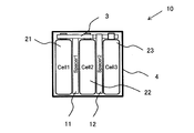
- FIG. 3 is a diagram illustrating an assembled battery.
- a three-cell connection simple assembled battery is illustrated as the assembled battery 10.
- the assembled battery is formed by connecting a number of unit cells (also referred to as cells) corresponding to desired output power in series, in parallel, or a combination thereof.
- the number of cells is appropriately set according to the required power.
- each unit cell is connected in series, and a partition member is disposed between the unit cells.
- the assembled battery 10 includes a cell 21 (Cell1: first single battery), a cell 22 (Cell2: second single battery), a cell 23 (Cell3: third single battery), A partition member 11 (Spacer1: first partition member) and a partition member 12 (Spacer2: second partition member) arranged between the cells and partitioning the cells are included.
- the assembled battery 10 further includes a bus bar 3 and a housing 4.
- partition member 11 and the partition member 12 are not distinguished, they are referred to as a partition member 1.
- the partition member 11 and the partition member 12 when not distinguishing the cell 21, the cell 22, and the cell 23, the notation of the cell 2 is used.
- the first unit cell, the second unit cell, and the third unit cell, and the first partition member and the second partition member mean relative positional relationships as shown in FIG.
- the unit cell is regarded as the first unit cell, and the second unit cell and the third unit cell, and the first partition member and the second partition member are determined.
- the cell 2 is, for example, a lithium ion secondary battery including a positive electrode and a negative electrode capable of inserting and extracting lithium ions, and an electrolyte.
- a secondary battery such as a lithium ion all solid battery, a nickel metal hydride battery, a nickel cadmium battery, or a lead storage battery can be applied.
- Partition member As the partition member 1, those described with reference to FIGS. 1 and 2 can be applied.
- the bus bar 3 is a conductor bar used for supplying electric power output from the cell to a load (for example, a motor), and is formed of a conductor such as aluminum.
- the housing 4 accommodates the partition member 1 and the cell 2.
- the housing 4 can be formed of, for example, a metal, a resin (polypropylene, etc.), a combination of a metal and a resin.
- the cell 2 and the partition member 1 may be fixed by sandwiching them between end plates of a plurality of cells 2 in which the partition members 1 are inserted between the cells and connecting the end plates with a connection plate. .
- the charged negative electrode (lithium-inserted carbon negative electrode) basically exhibits the same strong reducibility as lithium metal, and reacts with the electrolytic solution on the negative electrode surface. It is known that a film is formed, thereby inhibiting further reactions. Therefore, the chemical composition, structure, and thermal stability of the protective coating greatly affect the thermal stability of the charging negative electrode when the temperature rises.
- the reaction between the charging negative electrode and the electrolytic solution is explained by the formation of a protective coating followed by an explosive reductive decomposition reaction by destruction of the coating.
- ARC Accelelerating rate calibration
- Dahn et al. Define that a self-heating reaction proceeds inside the cell when the exothermic rate observed in ARC exceeds 0.04 ° C./min, and this can be imitated (reference).
- the cell 2 in the normal state is referred to as “single cell that maintains the normal state”, and the cell 2 that has deviated from the normal state and has not reached the abnormal heat generation state is referred to as “single cell that has deviated from the normal state”. Heat generated in the cell 2 is transmitted to other cells 2 through various transmission paths.
- the cell 2 in the normal state is referred to as “single cell that maintains the normal state”, and the cell 2 that has deviated from the normal state and has not reached the abnormal heat generation state is referred to as “single cell that has deviated from the normal state”. Heat generated in the cell 2 is transmitted to other cells 2 through various transmission paths.
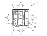
- FIG. 4 is a diagram illustrating a heat transfer path of the assembled battery.
- the heat generated in the cell 21 is (1) the partition member 11 disposed between the cells, (2) the bus bar 3, and (3)
- heat is also radiated to the outside of the casing of the assembled battery 10.
- the upper limit of the surface average temperature assumed when the cell 2 in contact with or close to the partition member 1 deviates from the normal state and does not reach the abnormal heat generation state is 180 ° C.
- the melt-down temperature of the general-purpose separator material is 160 to 200 ° C.
- the thermal resistance ( ⁇ 1 ) satisfies the above (formula 1) when the average temperature of one of the two surfaces in the thickness direction partitioning the cells 2 constituting the assembled battery 10 of the partition member 1 exceeds 180 ° C.
- the material of the general-purpose separator material is, for example, polyethylene, polypropylene or the like (Reference Document 7: Japanese Patent Application Laid-Open No. 2013-35293 / Reference Document 8: Japanese Patent Application Laid-Open No. 2015-208894).
- the upper limit value of the surface average temperature assumed when the cell 2 in contact with or close to the partition member 1 does not deviate from the normal state is 80 ° C.
- the boiling point of the general-purpose electrolyte component is 90 ° C. or higher as shown in Table 1 below.
- General-purpose electrolyte components are, for example, ethylene carbonate (EC), diethyl carbonate, dimethyl carbonate (DMC), and ethyl methyl carbonate (EMC).
- EC ethylene carbonate
- DMC dimethyl carbonate
- EMC ethyl methyl carbonate
- the thermal resistance ( ⁇ 2 ) satisfies the above (Formula 2).
- the heat transfer through the partition member 1 is promoted.
- the heat transfer resistance of the partition member 1 is lower than that of the conventional product, so that the temperature equalization between the cells 2 in the assembled battery 10 is successful and the deterioration of the cells 2 due to temperature unevenness is reduced. Can be expected.
- ⁇ Measuring means for thermal resistance per unit area ( ⁇ )> A means for controlling the thermal resistance ( ⁇ ) per unit area according to the surface temperature of the partition member 1 will be described. First, the material A and material B which comprise the partition member 1 are illustrated below.
- the material A is a material in which the thermal resistance ( ⁇ ) per unit area satisfies the above (Formula 1).
- the material A is, for example, a resin plate made of polycarbonate or butyl rubber.
- the material B is a material in which the thermal resistance ( ⁇ ) per unit area satisfies the above (Formula 2).
- the material B is, for example, ceramics, glass plate, polyethylene or the like in the solid state, and water, ethylene glycol, glycerin or the like in the liquid state.
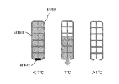
- the partition member 1 includes a substantially rectangular parallelepiped bag-shaped structure formed of a material A having a melting point at a temperature higher than T [° C.] (FIG. 5).
- the inside of the bag-like structure is filled with a material B that is in a liquid state at T [° C.], and an opening is provided on the lower surface of the bag-like structure to communicate the inside and the outside.
- the partition member 1 may have a structure in which a plurality of bag-like structures filled with the material B described above are arranged in the horizontal direction or the vertical direction.
- a stopper is not necessarily essential.
- the melting point of the material C may be equal to or lower than that of the material B.
- the plug may be formed of material B.
- the material B does not necessarily need to be liquid at T [° C.] and may be in a fluid state other than liquid.
- the thermal resistance ( ⁇ ) per unit area is determined by the material B in the bag-like structure (( Equation 2) is satisfied. Further, when the surface temperature of the partition member 1 becomes T [° C.] or higher, the material B flows down to the outside of the bag-like structure, so that the partition member 1 is composed of the material A.
- the thermal resistance ( ⁇ ) per unit area satisfies the above (Equation 1).
- the partition member 1 has a structure in which a lattice-like frame is provided inside the bag-like structure of FIG. 5 (FIG. 6). Inside the bag-like structure, the portion other than the frame is filled with the material B that is in a liquid state at T [° C.], and the lower surface of the bag-like structure is formed with the material C having a melting point near T [° C.]. It is closed with a stopper. When the plug formed of the material C is melted in the vicinity of T [° C.], the material B filled in the space portion of the bag-like structure flows down from the opening formed by melting of the plug to the outside. Designed.
- the frame acts to maintain the rigidity (strength) of the bag-like structure when the material B flows out.
- the thermal resistance per unit area ( ⁇ ) is filled by the material B filled in the space portion of the bag-shaped structure.
- the thermal resistance ( ⁇ ) per unit area satisfies the above (Equation 1).
- the heat transfer between the cells 2 constituting the assembled battery 10 reduces the amount of heat transferred from the cell 2 that has reached the abnormal heat generation state to the cell 2 that has deviated from the normal state, and the normal state from the cell 2 that has reached the abnormal heat generation state.
- the amount of heat transmitted to the cell 2 holding the normal state without passing through the electrode body of the deviated cell 2 and the amount of heat transferred from the cell 2 deviating from the normal state to the cell 2 holding the normal state are not suppressed. Be controlled.
- the electrode body of the cell 2 is a structure including an electrode, a separator, and an electrolytic solution, that is, a battery body.
- the cell 21 reaches an abnormal heat generation state, the cell 22 deviates from the normal state, and the cell 23 holds the normal state.
- the amount of heat transferred from the cell 21 to the cell 22 is suppressed, and the amount of heat transferred from the cell 21 to the cell 23 without passing through the electrode body of the cell 22 and the amount of heat transferred from the cell 22 to the cell 23 are controlled.
- the heat transfer between the cells 2 can be controlled by the switching function of the partition member 1. That is, the heat transfer resistance of the partition member 11 installed between the cell 22 that deviates from the normal state and the cell 21 that has reached the abnormal heat generation state increases, so that the amount of heat transmitted to the cell 22 out of the amount of heat generated by the cell 21. Decrease. Further, since the heat transfer resistance of the partition member 12 installed between the cell 22 deviating from the normal state and the cell 23 maintaining the normal state does not increase, the amount of heat transferred from the cell 22 to the cell 23 and the cell 21 The amount of heat transmitted to the cell 23 without passing through the electrode body of the cell 22 is not reduced.
- the amount of heat transmitted to the cell 23 without passing through the electrode body of the cell 22 is the structure of the cell 2 to the assembled battery 10 excluding the electrode body of the cell 22 other than the partition member 1 ( For example, it is transmitted via the bus bar 3 and the outer wall of the housing 4.
- the amount of heat generated by the cell 21 that has reached the abnormal heat generation state is maintained in the normal state while suppressing the amount of heat transmitted to the cell 22 that has deviated from the normal state.
- the temperature of each cell 2 in the assembled battery 10 is equalized. Accordingly, it is possible to suppress the cells 2 other than the cell 2 that has reached the abnormal heat generation state from reaching the abnormal heat generation state.
- the left-side cell 21 has a heat generation amount equivalent to 1.3 ⁇ 10 9 [J / m 3 ] (total calorific value estimated from the calorific value of the cell 2 using the NMC system positive electrode), and by solving the heat conduction equation by the finite element method under the conditions of the following examples and comparative examples, The temperature in the cell 2, the surface average temperature of the partition member 1, and the thermal resistance per unit area were estimated.
- COMSOL Multiphysics which is general-purpose physical simulation software manufactured by COMSOL AB, was used, and analysis was performed with reference to the following references 9 and 10. 4 is assumed as the heat transfer path between the cells (Reference 9: Japanese Patent Laid-Open No. 2006-010648 / Reference 10: RM Spotnitz et al., J. Power). Sources 163, 1080-1086, (2007)).
- the temperature inside the adjacent cells 22 and 23 the surface average temperature of the partition member 1 and the thermal resistance per unit area are estimated, and the partition The effect of suppressing the spread of fire due to the change in the heat transfer resistance of the member 1 was evaluated.
- the temperature inside each cell 2 assumed that the internal average temperature of the electrode body (structure containing an electrode, a separator, and electrolyte solution) was measured.
- Comparative Example 1 In Comparative Example 1, it is assumed that the partition member 1 is made of a general resin such as polypropylene (PP), the film thickness is 1 mm, and the thermal conductivity is 0.24 W / m ⁇ K.
- the bus bar 3 was assumed to be made of aluminum, and the thermal conductivity was 237 W / m ⁇ K.
- the casing 4 is assumed to be made of a general resin such as polypropylene, and the thermal conductivity is 0.24 W / m ⁇ K. Under these conditions, the temperature in each cell 2, the surface average temperature of the partition member 1, and the thermal resistance per unit area were estimated.
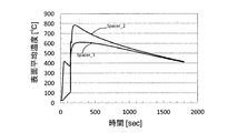
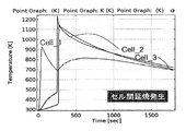
- FIG. 7 is a graph showing the temperature change inside the cell in Comparative Example 1.
- the vertical axis represents the absolute temperature [K] inside the cell 2 and the horizontal axis represents the time [second] after the cell 21 reaches the abnormal heat generation state.
- the temperature inside the cell 22 and the cell 23 exceeds 1000 K, suggesting that the fire spreading from the abnormally heat generated cell 21 to the cell 22 and the cell 23 occurs. It was.
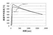
- FIG. 8 is a graph showing the transition of the average surface temperature of the partition member in Comparative Example 1.
- the average surface temperature of the partition member 1 was the average temperature on the surface of the cell 21 side where abnormal heat was generated.
- the vertical axis represents the surface average temperature [° C.] of the partition member 1
- the horizontal axis represents the time [seconds] from which the cell 21 reached the abnormal heat generation state.
- the surface average temperature of the partition member 11 (Spacer 1) increases rapidly to 400 ° C. immediately after the cell 21 reaches an abnormal heat generation state, and after about 150 seconds, the surface average temperature of the partition member 12 (Spacer 2) also increases rapidly. It was estimated that the temperature exceeded 700 ° C.
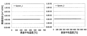
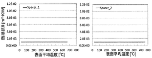
- FIG. 9 is a graph showing the transition of thermal resistance per unit area of the partition member in Comparative Example 1.
- the vertical axis represents the thermal resistance per unit area (m 2 ⁇ K / W), and the horizontal axis represents the surface average temperature (° C.) of the partition member 1.
- the values of thermal resistance ( ⁇ 1 ) per unit area at a surface average temperature of 190 ° C. of the partition member 11 (Spacer 1) and the partition member 12 (Spacer 2) are 4.2 ⁇ 10 ⁇ 3 m 2 ⁇ K / W, and an average temperature of 70
- the value of thermal resistance ( ⁇ 2 ) per unit area at ° C. was 4.2 ⁇ 10 ⁇ 3 m 2 ⁇ K / W. That is, the partition member 1 in the comparative example 1 does not satisfy any of the above conditions (Equation 1) and (Equation 2) regarding the thermal resistance per unit area.
- Example 1 the partition member 1 is assumed to be a high-function partition member having a switching function in which the thermal conductivity changes when the surface temperature of the abnormally heated cell side reaches a predetermined temperature, and the film thickness is 1.0 mm.
- Various conditions for the bus bar 3 and the housing 4 were the same as those in Comparative Example 1.
- the partition member 1 having a switching function is, for example, in a liquid state at 150 ° C. in the material B described above, in a bag-like structure made of a material having a melting point near 150 ° C. in the material A described above.
- the material B enclosed inside flows out to the outside of the bag-like structure.
- the partition member 1 has a switching temperature of 150 ° C., an initial thermal conductivity of 1.0 W / m ⁇ K, and a thermal conductivity after switching of 0.10 W / m ⁇ K.
- the surface temperature of the partition member 1 and the thermal resistance per unit area were estimated.
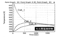
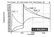
- FIG. 10 is a graph showing the temperature change inside the cell in Example 1.
- the vertical axis represents the absolute temperature [K] inside the cell 2 and the horizontal axis represents the time [second] after the cell 21 reaches the abnormal heat generation state.
- the internal temperature of the cell 22 and the cell 23 gradually increases after the cell 21 reaches the abnormal heat generation state, the cell 21 converges to about 430 K without reaching the abnormal heat generation state and suppresses the spread of the fire between the cells 2. It was shown that there is a possibility of being able to do it.
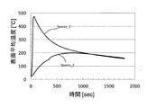
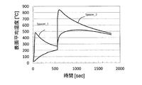
- FIG. 11 is a graph showing the transition of the average surface temperature of the partition member in Example 1.
- the vertical axis represents the average surface temperature (° C.) of the partition member 1
- the horizontal axis represents the time [seconds] from which the cell 21 reached the abnormal heat generation state.
- the surface average temperature of the partition member 11 (Spacer 1) rapidly rises to exceed 400 ° C., but the surface average temperature of the partition member 12 (Spacer 2) does not increase rapidly to about 160 ° C. It was estimated to converge.
- FIG. 12 is a graph showing changes in thermal resistance per unit area of the partition member in Example 1.
- the vertical axis represents the thermal resistance per unit area [m 2 ⁇ K / W], and the horizontal axis represents the surface average temperature [° C.] of the partition member 1.
- the value of the thermal resistance ( ⁇ 1 ) per unit area at the surface average temperature of 190 ° C. of the partition member 11 (Spacer 1) and the partition member 12 (Spacer 2) is 1.0 ⁇ 10 ⁇ 2 m 2 ⁇ K / W, and the average temperature is 70.
- the value of thermal resistance ( ⁇ 2 ) per unit area at ° C. was 1.0 ⁇ 10 ⁇ 3 m 2 ⁇ K / W. That is, the partition member 1 in Example 1 satisfies both the conditions of the above (formula 1) and (formula 2) regarding the thermal resistance per unit area.
- Comparative Example 2 Comparative Example 2 and Comparative Example 3 show examples in which the partition member 1 having no switching function is assumed in order to confirm the importance of the switching function of the partition member 1.
- the partition member 1 is assumed to be a partition member 1 having a lower thermal conductivity than Comparative Example 1, and the film thickness is 1.0 mm and the thermal conductivity is 0.10 W / m ⁇ K. .
- Various conditions for the bus bar 3 and the housing 4 were the same as those in Comparative Example 1.
- FIG. 13 is a graph showing the temperature change inside the cell in Comparative Example 2.
- the vertical axis represents the absolute temperature [K] inside the cell 2 and the horizontal axis represents the time [second] after the cell 21 reaches the abnormal heat generation state.
- Comparative Example 1 using a general resin partition member 1 the time required for the spread of fire from the abnormally heated cell 21 to the cell 22 and the cell 23 is extended, but the spread of fire is not suppressed. It has been shown.
- FIG. 14 is a graph showing the transition of the average surface temperature of the partition member in Comparative Example 2.
- the vertical axis represents the surface average temperature [° C.] of the partition member 1
- the horizontal axis represents the time [seconds] from which the cell 21 reached the abnormal heat generation state.
- the surface average temperature of the partition member 11 (Spacer 1) began to rise. From this result, when the heat insulating property of the partition member 1 was improved, it was estimated that in the initial stage when the cell 21 reached the abnormal heat generation state, the heat generation of the cell 21 was not efficiently removed, so that the fire spread was not suppressed. .
- FIG. 15 is a graph showing the transition of thermal resistance per unit area of the partition member in Comparative Example 2.
- the vertical axis represents the thermal resistance per unit area [m 2 ⁇ K / W], and the horizontal axis represents the surface average temperature [° C.] of the partition member 1.
- the value of the thermal resistance ( ⁇ 1 ) per unit area at the surface average temperature of 190 ° C. of the partition member 11 (Spacer 1) and the partition member 12 (Spacer 2) is 1.0 ⁇ 10 ⁇ 2 m 2 ⁇ K / W, and the average temperature is 70.
- the value of thermal resistance ( ⁇ 2 ) per unit area at ° C. was 1.0 ⁇ 10 ⁇ 2 m 2 ⁇ K / W. That is, the partition member 1 in the comparative example 2 satisfies the above-described condition of (Expression 1) regarding the thermal resistance per unit area, but does not satisfy the condition of (Expression 2).
- Comparative Example 3 (Comparative Example 3)
- the partition member 1 is assumed to be a partition member 1 having a higher thermal conductivity than that of Comparative Example 1, and the film thickness is 1.0 mm and the thermal conductivity is 1.0 W / m ⁇ K. .
- Various conditions for the bus bar 3 and the housing 4 were the same as those in Comparative Example 1.
- FIG. 16 is a graph showing the temperature change inside the cell in Comparative Example 3.
- the vertical axis represents the absolute temperature [K] inside the cell 2 and the horizontal axis represents the time [second] after the cell 21 reaches the abnormal heat generation state.
- Comparative Example 1 using a general resin partition member 1 the time required for the spread of fire from the abnormally heated cell 21 to the cell 22 and the cell 23 is shortened, and the cell 22 and the cell 23 are It was shown that abnormal heat was generated almost simultaneously with the cell 21.
- FIG. 17 is a graph showing the transition of the average surface temperature of the partition member in Comparative Example 3.
- the vertical axis represents the average surface temperature (° C.) of the partition member 1
- the horizontal axis represents the time [seconds] from which the cell 21 reached the abnormal heat generation state.
- the surface average temperature of the partition member 11 (Spacer 1) and the partition member 12 (Spacer 2) rises rapidly, and the surface average temperature exceeds 600 ° C. by 100 seconds. It was estimated. From this result, when the heat transfer property of the partition member 1 was improved, it was estimated that the heat spread at the time of abnormal heat generation of the cell 21 was rapidly propagated to the adjacent cells 22 and 23 and thus the fire spread was not suppressed. .
- FIG. 18 is a graph showing the transition of thermal resistance per unit area of the partition member in Comparative Example 3.
- the vertical axis represents the thermal resistance per unit area [m 2 ⁇ K / W], and the horizontal axis represents the surface average temperature (° C.) of the partition member 1.
- the value of the thermal resistance ( ⁇ 1 ) per unit area at a surface average temperature of 190 ° C. of the partition member 11 (Spacer 1) and the partition member 12 (Spacer 2) is 1.0 ⁇ 10 ⁇ 3 m 2 ⁇ K / W, and the average temperature is 70.
- the value of thermal resistance ( ⁇ 2 ) per unit area at ° C. was 1.0 ⁇ 10 ⁇ 3 m 2 ⁇ K / W. That is, the partition member 1 in Comparative Example 3 does not satisfy the above-described condition of (Expression 1) regarding the thermal resistance per unit area, but satisfies the condition of (Expression 2).
- Comparative Example 4 is a highly functional partition member having a switching function in which the thermal conductivity changes, and the thermal resistance value per unit area before and after the change is not in an appropriate range, so that the cell that abnormally generated heat An example in which fire spread to the cell has occurred is shown.
- the partition member 1 has a film thickness of 1.0 mm, a switching temperature of 150 ° C., an initial thermal conductivity of 0.24 W / m ⁇ K, and a thermal conductivity after switching of 0.10 W / m ⁇ K. It was.
- Various conditions for the bus bar 3 and the housing 4 were the same as those in Comparative Example 1.
- FIG. 19 is a graph showing the temperature change inside the cell in Comparative Example 4.
- the vertical axis represents the absolute temperature [K] inside the cell 2 and the horizontal axis represents the time [second] after the cell 21 reaches the abnormal heat generation state.
- the temperature inside the cell 22 and the cell 23 exceeds 1200K, and it is suggested that the spread of fire from the abnormally heated cell 21 to the cell 22 and the cell 23 occurs. It was done.
- FIG. 20 is a graph showing the transition of the average surface temperature of the partition member in Comparative Example 4.
- the vertical axis represents the surface average temperature [° C.] of the partition member 1
- the horizontal axis represents the time [seconds] from which the cell 21 reached the abnormal heat generation state.
- the surface average temperature of the partition member 11 (Spacer 1) rapidly increases and exceeds 400 ° C.
- the surface average temperature of the partition member 12 (Spacer 2) also increases rapidly. It was estimated to exceed 800 ° C. From this result, it was estimated that even if the partition member 1 has a switching function, if the thermal conductivity of the partition member 1 is not appropriately controlled, the fire spread is not suppressed.
- FIG. 21 is a graph showing changes in thermal resistance per unit area of the partition member in Comparative Example 4.
- the vertical axis represents the thermal resistance per unit area [m 2 ⁇ K / W], and the horizontal axis represents the surface average temperature [° C.] of the partition member 1.
- the value of the thermal resistance ( ⁇ 1 ) per unit area at the surface average temperature of 190 ° C. of the partition member 11 (Spacer 1) and the partition member 12 (Spacer 2) is 1.0 ⁇ 10 ⁇ 2 m 2 ⁇ K / W, and the average temperature is 70.
- the value of thermal resistance ( ⁇ 2 ) per unit area at ° C. was 4.2 ⁇ 10 ⁇ 3 m 2 ⁇ K / W. That is, the partition member 1 in Comparative Example 4 satisfies the above-described condition of (Expression 1) regarding the thermal resistance per unit area, but does not satisfy the condition of (Expression 2).
Landscapes
- Chemical & Material Sciences (AREA)
- Chemical Kinetics & Catalysis (AREA)
- Electrochemistry (AREA)
- General Chemical & Material Sciences (AREA)
- Engineering & Computer Science (AREA)
- Manufacturing & Machinery (AREA)
- Physics & Mathematics (AREA)
- Algebra (AREA)
- General Physics & Mathematics (AREA)
- Mathematical Analysis (AREA)
- Mathematical Optimization (AREA)
- Pure & Applied Mathematics (AREA)
- Aviation & Aerospace Engineering (AREA)
- Secondary Cells (AREA)
- Battery Mounting, Suspending (AREA)
Abstract
Description
θ1≧5.0 ×10⁻³ [m2・K/W] ・・・(式1)
θ2≦4.0 ×10⁻³ [m2・K/W] ・・・(式2)
前記二面の双方の平均温度が80℃以下である場合において、前記厚み方向の熱伝導率が5.0×10⁻²W/m・K以上50W/m・K以下である、[1]に記載の仕切り部材。
前記二面の双方の平均温度が80℃を超えない場合における前記厚み方向の単位面積当たりの熱抵抗(θ2)が下記式2を満たす、[1]乃至[3]のいずれか1項に記載の仕切り部材。
前記第1単電池と前記第2単電池間を仕切る第1仕切り部材と、前記第2単電池と前記第3単電池間を仕切る第2仕切り部材とを含み、
異常発熱状態に至った前記第1単電池からの熱により前記第2単電池が通常状態を逸脱した場合に、前記第1単電池から前記第2単電池へ前記第1仕切り部材を介して伝わる熱の量が前記第1仕切り部材によって抑制されるとともに、前記第1単電池から前記通常状態を保持している前記第3単電池へ伝わる熱の量が前記第2仕切り部材によって抑制されない、組電池。
前記仕切り部材は、厚み方向の二面を有し、これらのうちの一方の面は第1単電池と対向する第一面であり、また、他方の面は第2単電池と対向する第二面であって、
前記第1面の平均温度が80℃を超えない場合において、前記厚み方向の単位面積当たりの熱抵抗(θ2)が下記式2を満たして前記第1単電池からの熱を前記第2単電池へ前記仕切り部材を介して伝達し、
前記第1単電池が異常発熱状態に至るとともに前記第2単電池が前記第1単電池から前記仕切り部材を介して伝わる熱で通常状態を逸脱し、かつ前記第1単電池からの熱によって前記第1面の平均温度が180℃を超える場合において、前記厚み方向の単位面積当たりの熱抵抗(θ1)が下記式1を満たして前記第1単電池から前記仕切り部材を介して伝わる熱の量を抑制する、
組電池の熱伝達制御方法。
θ1≧5.0 ×10⁻³ [m2・K/W] ・・・(式1)
θ2≦4.0 ×10⁻³ [m2・K/W] ・・・(式2)
本発明に係る仕切り部材は、組電池を構成する単電池間を仕切る仕切り部材である。この仕切り部材は、組電池を構成する単電池間を仕切り、厚み方向の二面を有するものであって、前記二面のうちの一方の平均温度が180℃を超える場合における前記厚み方向の単位面積当たりの熱抵抗(θ1)が下記式1を満たし、かつ、前記二面の双方の平均温度が80℃を超えない場合における前記厚み方向の単位面積当たりの熱抵抗(θ2)が下記式2を満たす。
θ1≧5.0 ×10⁻³ [m2・K/W] ・・・(式1)
θ2≦4.0 ×10⁻³ [m2・K/W] ・・・(式2)
q = k(T1-T2)/d [W/m2] ・・・(1)
ここで、熱流束(q)は、単位面積当たりの熱抵抗(θ)を用いて以下の式(2)によって表すことができる。
q = (1/θ)(T1-T2) ・・・(2)
式(1)及び式(2)から、単位面積当たりの熱抵抗(θ)は、仕切り部材1Aの厚み方向の熱伝導率(k)及び仕切り部材の厚み(d)を用いて表すことができる。即ち、単位面積当たりの熱抵抗(θ)は以下の式(3)によって表すことができる。
θ = d/k [m2・K/W] ・・・(3)
R=R1+R2+R3+・・・+Rn ・・・(4)
また、n種類の材料が並列で並んでいる場合は、熱抵抗(R)は、以下の式(5)によって表すことができる。
1/R=1/R1+1/R2+1/R3+・・・+1/Rn ・・・(5)
Rn=θn/A ・・・(6)
式(4)を式(6)及び式(3)を用いて変形すると、以下の式(7)が得られる。
R=(θ1+θ2+θ3+・・・+θn)/A
=(d1/k1+d2/k2+d3/k3+・・・+dn/kn)/A ・・・(7)
複合部材の合成熱伝導率をκとすると、複合部材の総厚みはΣdnであるから、合成熱伝導率(κ)は、以下の式(8)のように表すこともできる。
R=(Σdn/κ)/A ・・・(8)
式(7)及び式(8)より、合成熱伝導率(κ)は、以下のように表すことができる。
κ=Σdn/Σ(dn/kn)
=(d1+d2+d3+・・・+dn)/(d1/k1+d2/k2+d3/k3+・・・+dn/kn)
Rn=θn/An ・・・(9)
式(5)を式(9)及び式(3)を用いて変形すると、以下の式(10)が得られる。
1/R=A1/θ1+A2/θ2+A3/θ3+・・・+An/θn
=(A1k1+A2k2+A3k3+・・・+Ankn)/d ・・・(10)
複合部材の合成熱伝導率をκとすると、複合部材の総断面積はΣAnであるから、合成熱伝導率(κ)は、以下の式(11)のように表すこともできる。
R=(d/κ)/ΣAn ・・・(11)
式(10)及び式(11)より、合成熱伝導率(κ)は、以下のように表すことができる。
κ=Σ(Ankn)/ΣAn
=(A1k1+A2k2+A3k3+・・・+Ankn)/(A1+A2+A3+・・・+An)
1-1)確認の対象とする仕切り部材の重心を決める。そしてこの重心から仕切り部材の一方の面に対して垂線を引き、その交点となる点を第1の点とする。この第1の点を含む面全体が160℃加熱となるように加熱する。なお、この加熱方法はある第1の点を含む面全体を160~300℃となるように温度を制御して加熱することができる方法であればその方法は制限されない。
1-2)第1の点を基準として、前記仕切り部材を前記厚み方向に二等分する分割面に対して前記第1の点と面対称の位置にある、他方の面上に存在する点を第2の点とする。
1-3)第1の点及び第2の点に基づいて、第1の点を含む面の温度について160℃から300℃まで昇温させる。ここで、160℃、180℃、210℃、240℃、270℃及び300℃のそれぞれの温度で系全体の温度が定常状態となったときについて、前述の方法により熱抵抗(θ1)を求める。
2-1)前記第1の点を含む面について面全体を100℃に加熱する。なお、この加熱方法は前記第1の点を含む面全体を20~1000℃となるように温度を制御して加熱することができる方法であればその方法は制限されない。
2-2)1-2)と同様にして第2の点を決定する。
2-3)第1の点及び第2の点に基づいて、第1の点を含む面について100℃から20℃まで降温させる。ここで、80℃、60℃、40℃、20℃のそれぞれの温度で系全体の温度が定常状態となったときについて、前述の方法により熱抵抗(θ2)を求める。
3-1)上記1-3)及び2-3)で求めた熱抵抗の値を用い、180℃より高い温度の各温度において上記式1を満たすかどうか、及び80℃よりも低い温度の各温度において上記式2を満たすかどうかを確認する。これらの各温度において式1及び式2を満たすかどうかを確認することにより、ある仕切り部材が本発明の仕切り部材に該当するかどうかを確認する。なお、前述の通り、本発明の仕切り部材は160℃より高い温度の各温度において上記式1を満たすことが好ましく、100℃より低い温度の各温度において上記式2を満たすことが好ましい。
仕切り部材1は、組電池を構成する構成要素の一つである。本発明に適用し得る組電池は、例えば、電気自動車(EV、Electric Vehicle)、ハイブリッド電気自動車(HEV、Hybrid Electric Vehicle)、プラグインハイブリッド電気自動車(PHEV、Plug-in Hybrid Electric Vehicle)、電動重機、電動バイク、電動アシスト自転車、船舶、航空機、電車、無停電電源装置(UPS、Uninterruptible Power Supply)、家庭用蓄電システム、風力/太陽光/潮力/地熱等の再生可能エネルギーを利用した電力系統安定化用蓄電池システム等に搭載される電池パックに適用される。但し、組電池は、上述のEV等以外の機器に電力を供給する電力源としても使用し得る。
セル2は、例えば、リチウムイオンを吸蔵・放出可能な正極及び負極、並びに電解質を備えるリチウムイオン二次電池である。リチウムイオン二次電池以外に、リチウムイオン全固体電池、ニッケル水素電池、ニッケルカドミウム電池、鉛蓄電池等の二次電池を適用し得る。
仕切り部材1は、図1及び図2を用いて説明したものを適用することができる。
バスバー3は、セルから出力される電力を負荷(例えば、モータ)へ供給するために使用される導体棒であり、例えばアルミニウム等の導体で形成される。筐体4は、仕切り部材1及びセル2を収容する。筐体4は、例えば、金属、樹脂(ポリプロピレン等)、金属及び樹脂の組み合わせで形成し得る。筐体として、セル間に仕切り部材1が挿入された複数のセル2のエンドプレートで挟み、エンドプレート間を接続板で接続して、セル2及び仕切り部材1が固定されるようにしてもよい。
セル2を構成する電極や電解液等を構成する化学物質の一部ないし全てが、セル2内部で発熱を伴いながら分解反応を起こすことにより、セル2の温度が昇温し、セル2の一部ないし全領域が200℃以上になる場合がある。この状態を「異常発熱状態」という。

仕切り部材1の表面温度によって単位面積当たりの熱抵抗(θ)を制御する手段について説明する。まず、仕切り部材1を構成する材料A及び材料Bを以下に例示する。
組電池10を構成するセル2間の熱移動は、異常発熱状態に至ったセル2から通常状態を逸脱したセル2へ伝わる熱量を抑制しつつ、異常発熱状態に至ったセル2から通常状態を逸脱したセル2の電極体を介さずに通常状態を保持しているセル2に伝わる熱量、及び通常状態を逸脱したセル2から通常状態を保持しているセル2へ伝わる熱量は抑制しないように制御される。なお、セル2の電極体は、電極、セパレータ、電解液を含む構造体、即ち電池の本体である。
比較例1では、仕切り部材1は、ポリプロピレン(PP)等の一般的な樹脂製であるものと想定し、膜厚は1mm、熱伝導率は0.24W/m・Kとした。バスバー3は、アルミニウム製であるものと想定し、熱伝導率は237W/m・Kとした。筐体4は、ポリプロピレン等の一般的な樹脂製であるものと想定し、熱伝導率は0.24W/m・Kとした。これらの条件下で、各セル2内の温度、並びに仕切り部材1の表面平均温度及び単位面積当たりの熱抵抗を推算した。
実施例1では、仕切り部材1は、異常発熱したセル側の表面温度が所定温度に達した時点で熱伝導率が変化するスイッチング機能を有する高機能仕切り部材であるものと想定し、膜厚は1.0mmとした。バスバー3及び筐体4についての各種条件は、比較例1と同様とした。
比較例2及び比較例3は、仕切り部材1のスイッチング機能の重要性を確認するため、スイッチング機能を持たない仕切り部材1を想定した例を示す。比較例2では、仕切り部材1は、比較例1よりも熱伝導率が低い仕切り部材1であるものと想定し、膜厚は1.0mm、熱伝導率は0.10W/m・Kとした。バスバー3及び筐体4についての各種条件は、比較例1と同様とした。
比較例3では、仕切り部材1は、比較例1よりも熱伝導率が高い仕切り部材1であるものと想定し、膜厚は1.0mm、熱伝導率は1.0W/m・Kとした。バスバー3及び筐体4についての各種条件は、比較例1と同様とした。
比較例4は、熱伝導率が変化するスイッチング機能を持つ高機能仕切り部材であっても、変化する前後の単位面積当たりの熱抵抗値が適切な範囲ではないために異常発熱したセルから他のセルへの延焼が発生した例を示す。
1、1A、1B、11、12 仕切り部材
2、21、22、23 セル、単電池
3 バスバー
4 筐体
Claims (9)
- 組電池を構成する単電池間を仕切り、厚み方向の二面を有する仕切り部材であって、
前記二面のうちの一方の平均温度が180℃を超える場合における前記厚み方向の単位面積当たりの熱抵抗(θ1)が下記式1を満たし、かつ、
前記二面の双方の平均温度が80℃を超えない場合における前記厚み方向の単位面積当たりの熱抵抗(θ2)が下記式2を満たす、
仕切り部材。
θ1≧5.0 ×10⁻³ [m2・K/W] ・・・(式1)
θ2≦4.0 ×10⁻³ [m2・K/W] ・・・(式2) - 前記二面の一方の平均温度が180℃以上である場合において、前記厚み方向の熱伝導率が2.0×10⁻²W/m・K以上2.0W/m・K以下であり、かつ、
前記二面の双方の平均温度が80℃以下である場合において、前記厚み方向の熱伝導率が5.0×10⁻²W/m・K以上50W/m・K以下である、請求項1に記載の仕切り部材。 - 前記単電池の厚みがL[mm]である場合に、前記厚み方向における厚みがL/50mm以上L/10mm以下である、請求項1又は2に記載の仕切り部材。
- 前記二面のうちの一方の平均温度が180℃を超えて300℃である場合における前記厚み方向の単位面積当たりの熱抵抗(θ1)が下記式1を満たし、かつ、
前記二面の双方の平均温度が80℃を超えない場合における前記厚み方向の単位面積当たりの熱抵抗(θ2)が下記式2を満たす、請求項1乃至3のいずれか1項に記載の仕切り部材。 - 請求項1乃至4のいずれか1項に記載の仕切り部材を含む組電池。
- 第1単電池、第2単電池、及び第3単電池を含む複数の単電池と、
前記第1単電池と前記第2単電池間を仕切る第1仕切り部材と、前記第2単電池と前記第3単電池間を仕切る第2仕切り部材とを含み、
異常発熱状態に至った前記第1単電池からの熱により前記第2単電池が通常状態を逸脱した場合に、前記第1単電池から前記第2単電池へ前記第1仕切り部材を介して伝わる熱の量が前記第1仕切り部材によって抑制されるとともに、前記第1単電池から前記通常状態を保持している前記第3単電池へ伝わる熱の量が前記第2仕切り部材によって抑制されない、組電池。 - 前記第1仕切り部材の単位面積当たりの熱抵抗が増加して前記第1単電池から前記第2単電池へ伝わる熱の量が抑制される、請求項6に記載の組電池。
- 前記第2単電池が前記通常状態を逸脱しても、前記第2仕切り部材の単位面積当たりの熱抵抗が増加せず前記第1単電池から前記第3単電池へ伝わる熱の量が抑制されない、請求項6又は7に記載の組電池。
- 仕切り部材により単電池間を仕切る組電池の熱伝達制御方法であって、
前記仕切り部材は、厚み方向の二面を有し、これらのうちの一方の面は第1単電池と対向する第一面であり、また、他方の面は第2単電池と対向する第二面であって、
前記第1面の平均温度が80℃を超えない場合において、前記厚み方向の単位面積当たりの熱抵抗(θ2)が下記式2を満たして前記第1単電池からの熱を前記第2単電池へ前記仕切り部材を介して伝達し、
前記第1単電池が異常発熱状態に至るとともに前記第2単電池が前記第1単電池から前記仕切り部材を介して伝わる熱で通常状態を逸脱し、かつ前記第1単電池からの熱によって前記第1面の平均温度が180℃を超える場合において、前記厚み方向の単位面積当たりの熱抵抗(θ1)が下記式1を満たして前記第1単電池から前記仕切り部材を介して伝わる熱の量を抑制する、
組電池の熱伝達制御方法。
θ1≧5.0 ×10⁻³ [m2・K/W] ・・・(式1)
θ2≦4.0 ×10⁻³ [m2・K/W] ・・・(式2)
Priority Applications (13)
| Application Number | Priority Date | Filing Date | Title |
|---|---|---|---|
| EP17886854.3A EP3565020B1 (en) | 2016-12-27 | 2017-12-27 | Partition member, assembled battery, and heat transmission control method for assembled battery |
| KR1020247009201A KR102934157B1 (ko) | 2016-12-27 | 2017-12-27 | 구획 부재, 조전지 및 조전지의 열전달 제어 방법 |
| CA3048603A CA3048603A1 (en) | 2016-12-27 | 2017-12-27 | Partition member, assembled battery and method for controlling heat transfer in an assembled battery |
| EP25166960.2A EP4567970A3 (en) | 2016-12-27 | 2017-12-27 | Partition member, assembled battery, and heat transmission control method for assembled battery |
| KR1020197019964A KR102650754B1 (ko) | 2016-12-27 | 2017-12-27 | 구획 부재, 조전지 및 조전지의 열전달 제어 방법 |
| CN201780080853.2A CN110114903B (zh) | 2016-12-27 | 2017-12-27 | 分隔构件、电池组和电池组的传热控制方法 |
| KR1020267004855A KR20260036375A (ko) | 2016-12-27 | 2017-12-27 | 구획 부재, 조전지 및 조전지의 열전달 제어 방법 |
| JP2018559611A JP6835101B2 (ja) | 2016-12-27 | 2017-12-27 | 仕切り部材、組電池及び組電池の熱伝達制御方法 |
| CN202211104938.9A CN115472995B (zh) | 2016-12-27 | 2017-12-27 | 分隔构件、电池组和电池组的传热控制方法 |
| US16/452,587 US20190319223A1 (en) | 2016-12-27 | 2019-06-26 | Partition member, assembled battery and method for controlling heat transfer in an assembled battery |
| US17/656,632 US11837705B2 (en) | 2016-12-27 | 2022-03-25 | Partition member, assembled battery and method for controlling heat transfer in an assembled battery |
| US18/500,945 US12412943B2 (en) | 2016-12-27 | 2023-11-02 | Partition member, assembled battery and method for controlling heat transfer in an assembled battery |
| US19/299,237 US20250372753A1 (en) | 2016-12-27 | 2025-08-13 | Partition member, assembled battery and method for controlling heat transfer in an assembled battery |
Applications Claiming Priority (2)
| Application Number | Priority Date | Filing Date | Title |
|---|---|---|---|
| JP2016254342 | 2016-12-27 | ||
| JP2016-254342 | 2016-12-27 |
Related Child Applications (1)
| Application Number | Title | Priority Date | Filing Date |
|---|---|---|---|
| US16/452,587 Continuation US20190319223A1 (en) | 2016-12-27 | 2019-06-26 | Partition member, assembled battery and method for controlling heat transfer in an assembled battery |
Publications (1)
| Publication Number | Publication Date |
|---|---|
| WO2018124231A1 true WO2018124231A1 (ja) | 2018-07-05 |
Family
ID=62709555
Family Applications (1)
| Application Number | Title | Priority Date | Filing Date |
|---|---|---|---|
| PCT/JP2017/047090 Ceased WO2018124231A1 (ja) | 2016-12-27 | 2017-12-27 | 仕切り部材、組電池及び組電池の熱伝達制御方法 |
Country Status (7)
| Country | Link |
|---|---|
| US (4) | US20190319223A1 (ja) |
| EP (2) | EP4567970A3 (ja) |
| JP (1) | JP6835101B2 (ja) |
| KR (3) | KR102650754B1 (ja) |
| CN (2) | CN110114903B (ja) |
| CA (1) | CA3048603A1 (ja) |
| WO (1) | WO2018124231A1 (ja) |
Cited By (4)
| Publication number | Priority date | Publication date | Assignee | Title |
|---|---|---|---|---|
| WO2020054875A1 (ja) | 2018-09-14 | 2020-03-19 | 三菱ケミカル株式会社 | 充填部材及び組電池 |
| JP2020161290A (ja) * | 2019-03-26 | 2020-10-01 | 三菱ケミカル株式会社 | 仕切り部材及び組電池 |
| WO2020196806A1 (ja) * | 2019-03-28 | 2020-10-01 | 三菱ケミカル株式会社 | 仕切り部材及び組電池 |
| WO2024143441A1 (ja) | 2022-12-28 | 2024-07-04 | 三菱ケミカル株式会社 | 仕切り部材及び組電池 |
Families Citing this family (6)
| Publication number | Priority date | Publication date | Assignee | Title |
|---|---|---|---|---|
| US11515587B2 (en) * | 2019-10-10 | 2022-11-29 | Robert Bosch Gmbh | Physics-based control of battery temperature |
| CN115009524B (zh) * | 2022-07-17 | 2023-11-17 | 西北工业大学 | 一种基于正常运行状态下的太阳能飞机热控系统及方法 |
| CN120453552A (zh) * | 2024-02-06 | 2025-08-08 | 比亚迪股份有限公司 | 电池组件和装置 |
| CN222867787U (zh) * | 2024-06-28 | 2025-05-13 | 比亚迪股份有限公司 | 电池组件、电池包和用电设备 |
| WO2026029616A1 (ko) * | 2024-08-02 | 2026-02-05 | 주식회사 엘지화학 | 흡열 장치 |
| KR20260020060A (ko) * | 2024-08-02 | 2026-02-10 | 주식회사 엘지화학 | 흡열 장치 |
Citations (10)
| Publication number | Priority date | Publication date | Assignee | Title |
|---|---|---|---|---|
| JPS49534B1 (ja) | 1969-05-16 | 1974-01-08 | ||
| JP2006010648A (ja) | 2004-06-29 | 2006-01-12 | Mitsubishi Chemicals Corp | 温度分布評価方法並びにシミュレーション装置及びシミュレーションプログラム |
| JP2010061982A (ja) * | 2008-09-03 | 2010-03-18 | Toyota Motor Corp | 蓄電装置 |
| JP2010097693A (ja) | 2008-10-14 | 2010-04-30 | Toyota Motor Corp | 蓄電装置 |
| JP2010165597A (ja) | 2009-01-16 | 2010-07-29 | Toyota Motor Corp | 蓄電装置 |
| JP2013035293A (ja) | 2006-08-31 | 2013-02-21 | Toray Battery Separator Film Co Ltd | 多層微多孔膜及びその製造方法、並びに電池用セパレータ及び電池 |
| JP2013536542A (ja) * | 2010-07-02 | 2013-09-19 | ローベルト ボツシユ ゲゼルシヤフト ミツト ベシユレンクテル ハフツング | 障害時にバッテリセルを熱的に分離させるための方法 |
| JP2013234244A (ja) * | 2012-05-08 | 2013-11-21 | Toyo Tire & Rubber Co Ltd | 熱伝導率可変材料 |
| JP5352681B2 (ja) | 2010-09-09 | 2013-11-27 | パナソニック株式会社 | 電池モジュール |
| JP2015208894A (ja) | 2014-04-24 | 2015-11-24 | 東レバッテリーセパレータフィルム株式会社 | ポリオレフィン製積層微多孔膜 |
Family Cites Families (20)
| Publication number | Priority date | Publication date | Assignee | Title |
|---|---|---|---|---|
| JPS5651210Y2 (ja) | 1976-10-07 | 1981-11-30 | ||
| JP2009135088A (ja) | 2007-10-29 | 2009-06-18 | Panasonic Corp | 電池パックおよび電池搭載機器 |
| JP4900534B2 (ja) | 2009-02-24 | 2012-03-21 | パナソニック株式会社 | 電池モジュールとそれを用いた電池モジュール集合体 |
| US8372269B2 (en) | 2009-10-02 | 2013-02-12 | Basf Corporation | Heavy metals trapping co-catalyst for FCC processes |
| JP5740103B2 (ja) * | 2009-10-19 | 2015-06-24 | 日東電工株式会社 | 熱伝導部材、及びそれを用いた組電池装置 |
| US20110293986A1 (en) * | 2009-11-25 | 2011-12-01 | Katsumi Kozu | Battery module |
| DE112010004856A5 (de) * | 2009-12-18 | 2012-12-13 | Magna E-Car Systems Gmbh & Co Og | Kühl-/Heizelement für einen Akkumulator |
| TWI419391B (zh) * | 2009-12-25 | 2013-12-11 | Ind Tech Res Inst | 電池系統中的散熱與熱失控擴散防護結構 |
| CN102117945A (zh) * | 2009-12-31 | 2011-07-06 | 财团法人工业技术研究院 | 电池系统中的散热与热失控扩散防护结构 |
| EP2555276A1 (en) * | 2010-03-30 | 2013-02-06 | Panasonic Corporation | Battery pack |
| JP5572442B2 (ja) * | 2010-04-27 | 2014-08-13 | 日立ビークルエナジー株式会社 | 液冷式蓄電システム |
| WO2012060031A1 (ja) * | 2010-11-05 | 2012-05-10 | パナソニック株式会社 | 電池モジュール |
| JP2013033723A (ja) * | 2011-07-04 | 2013-02-14 | Nissan Motor Co Ltd | 組電池 |
| US8993145B2 (en) * | 2011-09-19 | 2015-03-31 | Zee.Aero Inc. | Preventing cell thermal runaway propagation within a battery |
| KR101272524B1 (ko) * | 2011-09-20 | 2013-06-11 | 현대자동차주식회사 | 배터리 셀용 방열판 및 이를 갖는 배터리 모듈 |
| KR101417248B1 (ko) * | 2012-02-08 | 2014-07-09 | 현대자동차주식회사 | 배터리 셀 모듈용 방열 플레이트 및 이를 갖는 배터리 셀 모듈 |
| JP2014127403A (ja) * | 2012-12-27 | 2014-07-07 | Mitsubishi Heavy Ind Ltd | 電池モジュール |
| JP6135660B2 (ja) * | 2014-12-25 | 2017-05-31 | トヨタ自動車株式会社 | 組電池 |
| EP3062381B1 (en) * | 2015-02-26 | 2018-04-11 | Magneti Marelli S.p.A. | Cooling circuit with cooling fluid for lithium batteries, and a vehicle comprising said cooling circuit |
| CN105720225B (zh) * | 2016-03-31 | 2018-05-04 | 苏州工业园区职业技术学院 | 一种动力电池组快捷连接件 |
-
2017
- 2017-12-27 EP EP25166960.2A patent/EP4567970A3/en active Pending
- 2017-12-27 KR KR1020197019964A patent/KR102650754B1/ko active Active
- 2017-12-27 EP EP17886854.3A patent/EP3565020B1/en active Active
- 2017-12-27 KR KR1020267004855A patent/KR20260036375A/ko active Pending
- 2017-12-27 KR KR1020247009201A patent/KR102934157B1/ko active Active
- 2017-12-27 CN CN201780080853.2A patent/CN110114903B/zh active Active
- 2017-12-27 WO PCT/JP2017/047090 patent/WO2018124231A1/ja not_active Ceased
- 2017-12-27 JP JP2018559611A patent/JP6835101B2/ja active Active
- 2017-12-27 CA CA3048603A patent/CA3048603A1/en active Pending
- 2017-12-27 CN CN202211104938.9A patent/CN115472995B/zh active Active
-
2019
- 2019-06-26 US US16/452,587 patent/US20190319223A1/en not_active Abandoned
-
2022
- 2022-03-25 US US17/656,632 patent/US11837705B2/en active Active
-
2023
- 2023-11-02 US US18/500,945 patent/US12412943B2/en active Active
-
2025
- 2025-08-13 US US19/299,237 patent/US20250372753A1/en active Pending
Patent Citations (10)
| Publication number | Priority date | Publication date | Assignee | Title |
|---|---|---|---|---|
| JPS49534B1 (ja) | 1969-05-16 | 1974-01-08 | ||
| JP2006010648A (ja) | 2004-06-29 | 2006-01-12 | Mitsubishi Chemicals Corp | 温度分布評価方法並びにシミュレーション装置及びシミュレーションプログラム |
| JP2013035293A (ja) | 2006-08-31 | 2013-02-21 | Toray Battery Separator Film Co Ltd | 多層微多孔膜及びその製造方法、並びに電池用セパレータ及び電池 |
| JP2010061982A (ja) * | 2008-09-03 | 2010-03-18 | Toyota Motor Corp | 蓄電装置 |
| JP2010097693A (ja) | 2008-10-14 | 2010-04-30 | Toyota Motor Corp | 蓄電装置 |
| JP2010165597A (ja) | 2009-01-16 | 2010-07-29 | Toyota Motor Corp | 蓄電装置 |
| JP2013536542A (ja) * | 2010-07-02 | 2013-09-19 | ローベルト ボツシユ ゲゼルシヤフト ミツト ベシユレンクテル ハフツング | 障害時にバッテリセルを熱的に分離させるための方法 |
| JP5352681B2 (ja) | 2010-09-09 | 2013-11-27 | パナソニック株式会社 | 電池モジュール |
| JP2013234244A (ja) * | 2012-05-08 | 2013-11-21 | Toyo Tire & Rubber Co Ltd | 熱伝導率可変材料 |
| JP2015208894A (ja) | 2014-04-24 | 2015-11-24 | 東レバッテリーセパレータフィルム株式会社 | ポリオレフィン製積層微多孔膜 |
Non-Patent Citations (5)
| Title |
|---|
| HIROKI KOBAYASHI: "Synchrotron Radiation-Based Evaluation and Analysis Technologies for Positive Electrode Materials in Lithium Ion Secondary Batteries", 2011, SPRING-8 PROMOTION ASSOCIATION |
| J. DAHN ET AL., ELECTROCHEMISTRY COMMUNICATION, vol. 9, 2007, pages 2534 - 2540 |
| J. DAHN ET AL., ELECTROCHIMICA ACTA, vol. 49, 2004, pages 4599 - 4604 |
| R. M. SPOTNITZ ET AL., J. POWER SOURCES, vol. 163, 2007, pages 1080 - 1086 |
| See also references of EP3565020A4 |
Cited By (18)
| Publication number | Priority date | Publication date | Assignee | Title |
|---|---|---|---|---|
| JP7306401B2 (ja) | 2018-09-14 | 2023-07-11 | 三菱ケミカル株式会社 | 充填部材及び組電池 |
| KR102893848B1 (ko) * | 2018-09-14 | 2025-12-01 | 미쯔비시 케미컬 주식회사 | 충전 부재 및 조전지 |
| US11929478B2 (en) | 2018-09-14 | 2024-03-12 | Mitsubishi Chemical Corporation | Filling member and battery pack |
| CN112585803B (zh) * | 2018-09-14 | 2023-12-29 | 三菱化学株式会社 | 填充构件及电池组 |
| CN112585803A (zh) * | 2018-09-14 | 2021-03-30 | 三菱化学株式会社 | 填充构件及电池组 |
| KR20210056998A (ko) | 2018-09-14 | 2021-05-20 | 미쯔비시 케미컬 주식회사 | 충전 부재 및 조전지 |
| JPWO2020054875A1 (ja) * | 2018-09-14 | 2021-09-24 | 三菱ケミカル株式会社 | 充填部材及び組電池 |
| EP3819979A4 (en) * | 2018-09-14 | 2022-04-13 | Mitsubishi Chemical Corporation | FILLING ELEMENT AND BATTERY PACK |
| WO2020054875A1 (ja) | 2018-09-14 | 2020-03-19 | 三菱ケミカル株式会社 | 充填部材及び組電池 |
| JP7167802B2 (ja) | 2019-03-26 | 2022-11-09 | 三菱ケミカル株式会社 | 仕切り部材及び組電池 |
| JP2020161290A (ja) * | 2019-03-26 | 2020-10-01 | 三菱ケミカル株式会社 | 仕切り部材及び組電池 |
| JPWO2020196806A1 (ja) * | 2019-03-28 | 2020-10-01 | ||
| WO2020196806A1 (ja) * | 2019-03-28 | 2020-10-01 | 三菱ケミカル株式会社 | 仕切り部材及び組電池 |
| JP7464042B2 (ja) | 2019-03-28 | 2024-04-09 | 三菱ケミカル株式会社 | 仕切り部材及び組電池 |
| TWI853910B (zh) * | 2019-03-28 | 2024-09-01 | 日商三菱化學股份有限公司 | 分隔構件和電池組 |
| US12266773B2 (en) | 2019-03-28 | 2025-04-01 | Mitsubishi Chemical Corporation | Partition member and battery assembly |
| WO2024143441A1 (ja) | 2022-12-28 | 2024-07-04 | 三菱ケミカル株式会社 | 仕切り部材及び組電池 |
| EP4645560A1 (en) | 2022-12-28 | 2025-11-05 | Mitsubishi Chemical Corporation | Partition member and battery assembly |
Also Published As
| Publication number | Publication date |
|---|---|
| KR102650754B1 (ko) | 2024-03-22 |
| EP3565020A1 (en) | 2019-11-06 |
| EP3565020B1 (en) | 2025-04-16 |
| US20220223946A1 (en) | 2022-07-14 |
| US11837705B2 (en) | 2023-12-05 |
| CN110114903B (zh) | 2022-09-27 |
| US12412943B2 (en) | 2025-09-09 |
| EP3565020C0 (en) | 2025-04-16 |
| EP4567970A3 (en) | 2026-01-21 |
| CN110114903A (zh) | 2019-08-09 |
| US20190319223A1 (en) | 2019-10-17 |
| KR20240042179A (ko) | 2024-04-01 |
| US20240072325A1 (en) | 2024-02-29 |
| CN115472995A (zh) | 2022-12-13 |
| KR20260036375A (ko) | 2026-03-16 |
| EP4567970A2 (en) | 2025-06-11 |
| JPWO2018124231A1 (ja) | 2019-11-14 |
| KR102934157B1 (ko) | 2026-03-05 |
| CN115472995B (zh) | 2025-05-30 |
| KR20190097112A (ko) | 2019-08-20 |
| JP6835101B2 (ja) | 2021-02-24 |
| EP3565020A4 (en) | 2020-01-08 |
| US20250372753A1 (en) | 2025-12-04 |
| CA3048603A1 (en) | 2018-07-05 |
Similar Documents
| Publication | Publication Date | Title |
|---|---|---|
| JP6835101B2 (ja) | 仕切り部材、組電池及び組電池の熱伝達制御方法 | |
| JP7354842B2 (ja) | 仕切り部材及び組電池 | |
| EP3032607B1 (en) | Battery module | |
| KR101753213B1 (ko) | 배터리 셀, 그리고 이를 포함하는 배터리 모듈 및 배터리 팩 | |
| Liu et al. | Challenges and innovations of lithium-ion battery thermal management under extreme conditions: a review | |
| CN107408658B (zh) | 电池组 | |
| KR101270796B1 (ko) | 안전장치가 구비된 배터리 | |
| JP6954213B2 (ja) | 充填部材、組電池及び熱伝達の制御方法 | |
| JP7043813B2 (ja) | 仕切り部材及び組電池 | |
| US11901535B2 (en) | Partition member, assembled battery, and heat transfer control method of assembled battery | |
| US11929478B2 (en) | Filling member and battery pack | |
| JP6954214B2 (ja) | 充填部材、組電池、及び熱伝達の制御方法 | |
| JP7285878B2 (ja) | 二次電池、電池モジュールおよび二次電池の製造方法 | |
| Sangiri et al. | Electro-thermal modeling of Lithium-ion cell for higher discharge rate applications |
Legal Events
| Date | Code | Title | Description |
|---|---|---|---|
| 121 | Ep: the epo has been informed by wipo that ep was designated in this application |
Ref document number: 17886854 Country of ref document: EP Kind code of ref document: A1 |
|
| ENP | Entry into the national phase |
Ref document number: 2018559611 Country of ref document: JP Kind code of ref document: A |
|
| ENP | Entry into the national phase |
Ref document number: 3048603 Country of ref document: CA |
|
| NENP | Non-entry into the national phase |
Ref country code: DE |
|
| ENP | Entry into the national phase |
Ref document number: 20197019964 Country of ref document: KR Kind code of ref document: A |
|
| ENP | Entry into the national phase |
Ref document number: 2017886854 Country of ref document: EP Effective date: 20190729 |
|
| WWG | Wipo information: grant in national office |
Ref document number: 2017886854 Country of ref document: EP |