WO2018123067A1 - コマンドデータ送信装置、ローカルエリア装置、機器制御システム、コマンドデータ送信装置の制御方法、ローカルエリア装置の制御方法、機器制御方法、及びプログラム - Google Patents
コマンドデータ送信装置、ローカルエリア装置、機器制御システム、コマンドデータ送信装置の制御方法、ローカルエリア装置の制御方法、機器制御方法、及びプログラム Download PDFInfo
- Publication number
- WO2018123067A1 WO2018123067A1 PCT/JP2016/089215 JP2016089215W WO2018123067A1 WO 2018123067 A1 WO2018123067 A1 WO 2018123067A1 JP 2016089215 W JP2016089215 W JP 2016089215W WO 2018123067 A1 WO2018123067 A1 WO 2018123067A1
- Authority
- WO
- WIPO (PCT)
- Prior art keywords
- command data
- command
- local area
- operation instruction
- transmitted
- Prior art date
Links
Images


Classifications
-
- H—ELECTRICITY
- H04—ELECTRIC COMMUNICATION TECHNIQUE
- H04L—TRANSMISSION OF DIGITAL INFORMATION, e.g. TELEGRAPHIC COMMUNICATION
- H04L61/00—Network arrangements, protocols or services for addressing or naming
- H04L61/09—Mapping addresses
- H04L61/25—Mapping addresses of the same type
- H04L61/2503—Translation of Internet protocol [IP] addresses
- H04L61/2514—Translation of Internet protocol [IP] addresses between local and global IP addresses
-
- G—PHYSICS
- G10—MUSICAL INSTRUMENTS; ACOUSTICS
- G10L—SPEECH ANALYSIS OR SYNTHESIS; SPEECH RECOGNITION; SPEECH OR VOICE PROCESSING; SPEECH OR AUDIO CODING OR DECODING
- G10L15/00—Speech recognition
- G10L15/22—Procedures used during a speech recognition process, e.g. man-machine dialogue
-
- H—ELECTRICITY
- H04—ELECTRIC COMMUNICATION TECHNIQUE
- H04L—TRANSMISSION OF DIGITAL INFORMATION, e.g. TELEGRAPHIC COMMUNICATION
- H04L12/00—Data switching networks
- H04L12/28—Data switching networks characterised by path configuration, e.g. LAN [Local Area Networks] or WAN [Wide Area Networks]
- H04L12/2803—Home automation networks
- H04L12/283—Processing of data at an internetworking point of a home automation network
- H04L12/2836—Protocol conversion between an external network and a home network
-
- H—ELECTRICITY
- H04—ELECTRIC COMMUNICATION TECHNIQUE
- H04L—TRANSMISSION OF DIGITAL INFORMATION, e.g. TELEGRAPHIC COMMUNICATION
- H04L12/00—Data switching networks
- H04L12/28—Data switching networks characterised by path configuration, e.g. LAN [Local Area Networks] or WAN [Wide Area Networks]
- H04L12/46—Interconnection of networks
- H04L12/4604—LAN interconnection over a backbone network, e.g. Internet, Frame Relay
- H04L12/462—LAN interconnection over a bridge based backbone
- H04L12/4625—Single bridge functionality, e.g. connection of two networks over a single bridge
-
- H—ELECTRICITY
- H04—ELECTRIC COMMUNICATION TECHNIQUE
- H04L—TRANSMISSION OF DIGITAL INFORMATION, e.g. TELEGRAPHIC COMMUNICATION
- H04L61/00—Network arrangements, protocols or services for addressing or naming
- H04L61/09—Mapping addresses
- H04L61/10—Mapping addresses of different types
- H04L61/103—Mapping addresses of different types across network layers, e.g. resolution of network layer into physical layer addresses or address resolution protocol [ARP]
-
- H—ELECTRICITY
- H04—ELECTRIC COMMUNICATION TECHNIQUE
- H04L—TRANSMISSION OF DIGITAL INFORMATION, e.g. TELEGRAPHIC COMMUNICATION
- H04L61/00—Network arrangements, protocols or services for addressing or naming
- H04L61/09—Mapping addresses
- H04L61/25—Mapping addresses of the same type
- H04L61/2503—Translation of Internet protocol [IP] addresses
- H04L61/256—NAT traversal
-
- H—ELECTRICITY
- H04—ELECTRIC COMMUNICATION TECHNIQUE
- H04L—TRANSMISSION OF DIGITAL INFORMATION, e.g. TELEGRAPHIC COMMUNICATION
- H04L67/00—Network arrangements or protocols for supporting network services or applications
- H04L67/01—Protocols
- H04L67/12—Protocols specially adapted for proprietary or special-purpose networking environments, e.g. medical networks, sensor networks, networks in vehicles or remote metering networks
- H04L67/125—Protocols specially adapted for proprietary or special-purpose networking environments, e.g. medical networks, sensor networks, networks in vehicles or remote metering networks involving control of end-device applications over a network
-
- G—PHYSICS
- G10—MUSICAL INSTRUMENTS; ACOUSTICS
- G10L—SPEECH ANALYSIS OR SYNTHESIS; SPEECH RECOGNITION; SPEECH OR VOICE PROCESSING; SPEECH OR AUDIO CODING OR DECODING
- G10L15/00—Speech recognition
- G10L15/22—Procedures used during a speech recognition process, e.g. man-machine dialogue
- G10L2015/223—Execution procedure of a spoken command
-
- H—ELECTRICITY
- H04—ELECTRIC COMMUNICATION TECHNIQUE
- H04L—TRANSMISSION OF DIGITAL INFORMATION, e.g. TELEGRAPHIC COMMUNICATION
- H04L67/00—Network arrangements or protocols for supporting network services or applications
- H04L67/01—Protocols
- H04L67/02—Protocols based on web technology, e.g. hypertext transfer protocol [HTTP]
- H04L67/025—Protocols based on web technology, e.g. hypertext transfer protocol [HTTP] for remote control or remote monitoring of applications
Definitions
- the present invention relates to a command data transmission device, a local area device, a device control system, a command data transmission device control method, a local area device control method, a device control method, and a program.
- a device that receives a command transmitted via a local area network (LAN) and performs an operation corresponding to the command is known (Patent Document 1). Such devices can be controlled via a LAN.
- a private IP address that is valid only in the local area is often set for the above-mentioned devices. Since a command cannot be directly transmitted to a device with a private IP address set via the Internet (wide area network), the device cannot be controlled via the Internet using the above command.
- the present invention has been made in view of the above problems, and an object of the present invention is to provide command data capable of controlling a device via a wide area network such as the Internet while using a command used in a local area. It is an object to provide a transmission device, a local area device, a device control system, a command data transmission device control method, a local area device control method, a device control method, and a program.
- a command data transmission device includes an operation instruction receiving unit that receives an operation instruction for a device installed in a local area, and the device that performs an operation according to the operation instruction.
- command data generating means for generating command data indicating a command to be transmitted to the device and a destination when the command is transmitted to the device via a transmission means in the local area
- Command data transmitting means for transmitting the command data generated by the command data generating means to a local area device to be transmitted via a wide area network.
- the local area device provides command data indicating a destination to which a command is to be transmitted via a transmission means in a local area and a command to be transmitted to the destination via the transmission means.
- Command data receiving means for receiving the command
- command transmitting means for transmitting the command to the destination via the transmission means based on the command data.
- the device control system is a command data transmitting device capable of transmitting command data via a wide area network, an operation instruction receiving means for receiving an operation instruction for a device installed in a local area, Based on the operation instruction, a command to be transmitted to the device in order to perform an operation according to the operation instruction, and when the command is transmitted to the device via a transmission unit in the local area Command data generating means for generating command data indicating a destination and command data generated by the command data generating means are transmitted to a local area device installed in the local area via a wide area network.
- a command data transmission means including a command data transmission means;
- a command data receiving means for receiving the command data via the wide area network, and a command transmission for sending the command to the destination via the transmission means based on the command data.
- the method for controlling a command data transmitting apparatus includes an operation instruction receiving step for receiving an operation instruction for a device installed in a local area, and performing an operation according to the operation instruction based on the operation instruction.
- a command data generation step for generating command data indicating a command to be transmitted to the device and a destination when the command is transmitted to the device via a transmission means in the local area;
- the local area device control method provides command data indicating a destination to which a command is to be transmitted via a transmission means in a local area and a command to be transmitted to the destination via the transmission means.
- a command data receiving step for receiving via a wide area network; and a command transmitting step for transmitting the command to the destination via the transmission means based on the command data.
- the local area device control method includes an operation instruction receiving step in which the command data transmission device receives an operation instruction for a device installed in the local area, and the command data transmission device is based on the operation instruction.
- a command data generating step for generating command data; and the command data transmitting device sends command data generated by the command data generating means to a local area device installed in the local area via a wide area network.
- a command data transmission step to be transmitted, and the local A rear device receives the command data via the wide area network, and a command data reception step, and the local area device transmits the command to the destination via the transmission means based on the command data.
- Command sending step in which the command data transmission device receives an operation instruction for a device installed in the local area, and the command data transmission device is based on the operation instruction.
- the program according to the present invention is an operation instruction accepting unit that accepts an operation instruction for a device installed in a local area, and causes the device to perform an operation according to the operation instruction based on the operation instruction.
- Command data generation means for generating command data indicating a command to be transmitted and a destination when the command is transmitted to the device via transmission means in the local area, and installed in the local area
- This is a program for causing a local area device to function as a computer as command data transmitting means for transmitting command data generated by the command data generating means via a wide area network.
- An information storage medium according to the present invention is a computer-readable information storage medium recording the above program.
- the program according to the present invention sends command data indicating a destination to which a command is to be transmitted via a transmission means in a local area and a command to be transmitted to the destination via the transmission means via a wide area network.
- a command data receiving unit that receives the command and a command transmission unit that transmits the command to the destination via the transmission unit based on the command data.
- An information storage medium according to the present invention is a computer-readable information storage medium recording the above program.
- the present invention it is possible to control a device via a wide area network such as the Internet while using a command used in a local area.
- FIG. 1 shows the configuration of a device control system according to an embodiment of the present invention.
- the device control system 1 includes a first device 20-1, a second device 20-2, a third device 20-3, a fourth device 20-4, a voice input device 30, and a voice recognition device 40. And a command processing system 50.
- the first device 20-1, the second device 20-2, the third device 20-3, and the fourth device 20-4 may be collectively referred to as “device 20”.
- the device 20 and the voice input device 30 are installed in the local area and connected to the LAN 2.
- the LAN 2 may be a wired LAN or a wireless LAN.
- the LAN 2 is connected to the Internet 6 (wide area network) via the router 4.
- the voice recognition device 40 and the command processing system 50 are installed outside the local area. That is, when viewed from the device 20 and the voice input device 30, the voice recognition device 40 and the command processing system 50 are installed on the Internet 6 side.
- the “local area” is an area in a limited range in which communication via the LAN 2 is possible.
- the “wide area” is an area including the outside of the local area, and is an area in which communication via the Internet 6 is possible.
- the device 20 is a device to be controlled by the device control system 1. In FIG. 1, only four devices 20 are shown, but five or more devices 20 may be included, or only three or less devices 20 may be included.
- the device 20 is an audio device or an audiovisual device.
- the device 20 is an AV receiver, an AV amplifier, a speaker, an optical disc playback device (such as a Blu-ray Disc (registered trademark) player or a DVD (registered trademark) player), or a television receiver.
- the device 20 may be a musical instrument (electronic musical instrument or electric musical instrument).
- the device 20 may be other devices.
- the first device 20-1 is an AV receiver
- the second device 20-2 has an automatic performance function (a function for automatically performing performance by reproducing keyboard and pedal movements based on data).
- the electronic device is an electronic piano
- the third device 20-3 is a television receiver
- the fourth device 20-4 is a Blu-ray disc player.
- the second device 20-2 is connected to the external input terminal of the first device 20-1 via an audio cable
- the third device 20-3 is connected to the first device via an HDMI (High-Definition Multimedia Interface: registered trademark) cable.
- the first device 20-1 is connected to the first HDMI terminal (HDMI1)
- the fourth device 20-4 is connected to the second HDMI terminal (HDMI2) of the first device 20-1 via the HDMI cable.
- the MAC address of the first device 20-1 is “aa: bb: cc: dd: ee: 11”, and the private IP address “192.168.0.2” is assigned to the first device 20-1. Is set.
- the MAC address of the second device 20-2 is “aa: bb: cc: dd: ee: 22”, and the private IP address “192.168.0.3” is set for the second device 20-2.
- the MAC address of the third device 20-3 is “aa: bb: cc: dd: ee: 33”, and the private IP address “192.168.0.4” is set for the third device 20-3. ing.
- the MAC address of the fourth device 20-4 is “aa: bb: cc: dd: ee: 44”, and the private IP address “192.168.0.5” is set for the fourth device 20-4. ing.
- the first device 20-1 includes a control unit 21, a storage unit 22, and a communication unit 23.
- the control unit 21 includes at least one microprocessor (CPU), and executes processing according to a program stored in the storage unit 22.
- the storage unit 22 includes a main storage unit (for example, RAM) and an auxiliary storage unit (for example, a nonvolatile semiconductor memory, a hard disk drive, or a solid state drive).
- the storage unit 22 is for storing programs and data.
- the communication unit 23 is for transmitting and receiving data to and from other devices.
- the second device 20-2, the third device 20-3, and the fourth device 20-4 also include a control unit 21, a storage unit 22, and a communication unit 23.
- the device 20 may include a component (for example, an optical disk drive or a memory card slot) for reading a program or data stored in an information storage medium (for example, an optical disk or a memory card). And a program may be supplied to the apparatus 20 via an information storage medium. The program may be supplied to the device 20 via the Internet 6.
- a component for example, an optical disk drive or a memory card slot
- an information storage medium for example, an optical disk or a memory card.
- a program may be supplied to the apparatus 20 via an information storage medium.
- the program may be supplied to the device 20 via the Internet 6.
- the device 20 receives a command transmitted via the LAN 2 (an example of a transmission means in the local area) and performs an operation corresponding to the command. For this reason, the apparatus 20 can be controlled via LAN2. That is, by transmitting a command from the terminal such as a smartphone or a tablet computer to the device 20 via the LAN 2, it is possible to cause the device 20 to perform an operation corresponding to the command.
- the terminal such as a smartphone or a tablet computer
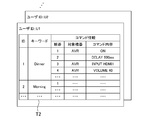
- FIG. 2 shows examples of commands.
- the commands C1 to C4 shown in FIG. 2 are examples of commands for the first device 20-1 (AV receiver), and the commands C5 to C7 are examples of commands for the second device 20-2 (electronic piano).
- the command shown in FIG. 2 uses the HTTP protocol, and a URL is set as the command.
- the command is transmitted to the first device 20-1 or the second device 20-2 in the form of an HTTP request.
- an HTTP daemon is activated, and an HTTP request is accepted by the HTTP daemon, and processing corresponding to the HTTP request is executed.
- an HTTP response indicating the processing result is returned to the command transmission source.
- a command using the HTTP protocol can be transmitted to the third device 20-3 and the fourth device 20-4.
- the command C1 is a command for starting the first device 20-1 from the standby state (non-starting state).
- the “standby state” is a state in which power consumption is reduced compared to the normal state (start-up state). In other words, the standby state is not a state in which the power is completely turned off, and the network communication function and the like are enabled even in the standby state, and command data is received, commands are executed (transmitted), and commands are accepted It is possible to
- the command C2 is a command for switching the input of the first device 20-1 to the external input.
- the first device 20-1 (AV receiver) has a plurality of input terminals (for example, HDMI terminal, external input terminal, etc.), and a plurality of devices 20 including the second device 20-2 are connected to the plurality of input terminals. Is done.
- a speaker (an example of sound emission means) is connected to the first device 20-1, and the first device 20-1 emits a sound signal input from one of the input terminals from the speaker.
- the command C2 is a command for switching the audio signal supplied to the speaker to the audio signal input from the external input terminal.
- Command C3 is a command for setting the output volume.
- the command C4 is a command for requesting device information of the first device 20-1.
- the device information (model name or current status information) of the first device 20-1 is returned to the transmission source of the command C4.
- the command C5 is a command for starting the second device 20-2 from the standby state.
- the command C6 is a command for starting the automatic performance of the second device 20-2 (electronic piano).
- the command C7 is a command for requesting device information of the second device 20-2.
- the command formats of the second device 20-2 and the first device 20-1 may be the same or different.
- the command format may be the same or different between the first device 20-1, the second device 20-2, the third device 20-3, and the fourth device 20-4.
- the voice input device 30 includes a microphone and accepts voice input.
- the voice input device 30 is used for the user to input an operation instruction to the device 20 by voice. For example, when an electronic piano manufactured by Company X is desired to be automatically played, the user inputs “X piano play” or the like to the voice input device 30. In addition, for example, when the user wants to play music on the audio system manufactured by Company X installed in the living room, the user inputs “X play in living room” or the like to the voice input device 30.
- Voice data indicating voice (operation instruction) input to the voice input device 30 is transmitted to the voice recognition device 40 via the Internet 6 together with the user ID.
- the voice recognition device 40 is realized by a server computer, for example.
- the voice recognition device 40 executes voice recognition processing to convert the voice data into data in a format that can be easily understood by the program (command processing system 50). For example, voice data is converted into text data of a predetermined format.
- the operation instruction converted into text data is transmitted to the command processing system 50 together with the user ID.
- the user ID may be given by any Internet-side device (process) until the voice data is transmitted to the command processing system 50.
- a different command processing system 50 is prepared for each manufacturer of the device 20, an operation instruction for the device 20 manufactured by the X company is transmitted to the command processing system 50 for the device 20 manufactured by the X company. . If different command processing systems 50 are prepared for each command format, an operation instruction for the device 20 is transmitted to the command processing system 50 for the command format adopted by the device 20. .
- the command processing system 50 includes a command data transmission device 10, a database 60, and an MQTT (Message Queueing Telemetry Transport) server 70.
- MQTT Message Queueing Telemetry Transport
- the database 60 stores various data.
- the database 60 stores information on the devices 20 owned by each user.
- FIG. 3 shows an example of a device table stored in the database 60.
- the device table T1 is stored for each user (in association with the user ID).
- the user ID used in the command processing system 50 may be different from or the same as the user ID used in the voice input device 30 and the voice recognition device 40. However, when these user IDs are different, correspondence data for converting those user IDs needs to be stored in the command processing system 50 or the voice recognition device 40.
- the device table T1 includes “ID”, “name”, “model”, “MAC address”, “IP address”, “command type”, “terminal”, “volume range”, “connection destination”. ",” Reception availability ", and” Alternative device “fields.
- the “ID” field indicates information for uniquely identifying each device 20 owned by the user.
- the first device 20-1 corresponds to the device ID “1”
- the second device 20-2 corresponds to the device ID “2”.
- “Name” field indicates the name of the device 20. This name is used by the user to specify the device 20 that is the target of the operation instruction. As the name, an arbitrary name set by the user may be used, or a name set by the manufacturer of the device 20 or the like may be used.
- the “model” field indicates the model name (model name) of the device 20.
- the “MAC address” and “IP address” fields indicate the MAC address and IP address set for the wired or wireless network interface card included in the device 20.
- the “command type” field indicates the type (system) of commands used in the device 20. When the command type is determined for each model, a table that associates the model with the command type is provided separately, and instead, the “command type” field is not provided in the device table T1. May be.
- the “terminal” field indicates a list of input terminals provided in the device 20.
- the “volume range” field indicates a volume range that can be set by the device 20. In the “connection destination” field, when the device 20 is connected to the input terminal of the other device 20 and the sound output from the device 20 is input to the other device 20, the other device to which the device 20 is connected is displayed. 20 input terminals are shown.
- the “reception availability” field indicates whether command data can be received via the Internet 6.
- the command data will be described later. For example, “0” or “1” is registered in the “reception availability” field. “0” indicates that command data cannot be received via the Internet 6, and “1” indicates that command data can be received via the Internet 6.
- the “alternative device” field indicates a device 20 (alternative device) that receives command data instead of the device 20 when the device 20 cannot receive command data via the Internet 6.
- the device table T1 is registered by each user.
- the user can register the information of the device 20 owned by the user in the device table T1 by accessing the command data transmitting apparatus 10 from the terminal.
- information on the device 20 may be transmitted to the command processing system 50 (command data transmitting apparatus 10) together with the user ID and registered in the device table T1.
- the database 60 also stores data other than the device table T1. For example, data indicating a correspondence relationship between an operation instruction and a command (in other words, data for converting the operation instruction into a command) is stored in the database 60. This data is stored for each command type (system).
- the command data transmission device 10 is realized by a server computer, for example. As illustrated in FIG. 1, the command data transmission device 10 includes a control unit 11, a storage unit 12, and a communication unit 13. The control unit 11, the storage unit 12, and the communication unit 13 are the same as the control unit 21, the storage unit 22, and the communication unit 23.
- the command data transmitting apparatus 10 may include a component (for example, an optical disk drive or a memory card slot) for reading a program or data stored in an information storage medium (for example, an optical disk or a memory card). And a program may be supplied to the command data transmitter 10 via an information storage medium. The program may be supplied to the command data transmission device 10 via the Internet 6.
- the command data transmission device 10 can access the database 60.
- the command data transmission device 10 and the database 60 may be realized by one server computer or may be realized by another server computer.
- the command data transmission device 10 receives an operation instruction for the device 20, generates command data based on the operation instruction, and transmits the command data to the device 20 or another device 20 (alternative device). As will be described later, the command data is transmitted to the device 20 or another device 20 (alternative device) via the MQTT server 70.
- the MQTT server 70 is for transmitting and receiving data using the MQTT protocol. Command data transmitting apparatus 10 and MQTT server 70 may be realized by one server computer, or may be realized by another server computer.
- FIG. 4 shows an example of functional blocks realized by the command data transmitting apparatus 10 and the device 20.
- the command data transmitting apparatus 10 includes an operation instruction receiving unit 110, a command data generating unit 120, a command data transmitting unit 130, a device information acquiring unit 140, a determining unit 150, a notifying unit 160, and a keyword command registering unit. 170 is included. These functional blocks are realized by the control unit 11, for example.
- the device 20 includes a command data receiving unit 210, a command transmitting unit 220, and a device information transmitting unit 230. These functional blocks are realized by the control unit 21, for example.
- the operation instruction receiving unit 110 receives an operation instruction for the first device 20-1 or the second device 20-2.
- the operation instruction receiving unit 110 receives, from the voice recognition device 40, an operation instruction converted into data in a format that can be easily understood by a program such as text data by the voice recognition device 40.
- the command data generation unit 120 sends a command to be sent to the first device 20-1 or the second device 20-2 to perform an operation according to the operation instruction, and the command is sent to the first device via the LAN 2.
- Command data indicating a destination at the time of transmission to 20-1 or the second device 20-2 is generated.
- Fig. 5 shows an example of command data.
- the command data D1 shown in FIG. 5 is an example of command data generated when an operation instruction for starting the first device 20-1 from the standby state is received. That is, the command data D1 is an example of command data generated when it is desired to execute the command C1 shown in FIG. 2 on the first device 20-1.
- the command data D1 includes items “type”, “id”, and “command”.
- the item “type” indicates the type of data. In the example illustrated in FIG. 5, “cmd” is set to the item “type”. This indicates that the data is command data.
- the item “id” indicates identification information for uniquely identifying data (command data).
- the item “command” indicates the contents of the command data.
- the item “command” includes items “ip”, “path”, and “method”.
- the item “ip” indicates the destination of the command.
- the IP address of the first device 20-1 is set in the item “ip”.
- the item “path” corresponds to the command body.
- the item “ip” corresponds to the IP address portion of the command C1, and the item “path” corresponds to the portion after the IP address of the command C1.
- the item “method” indicates an HTTP protocol method to be used.
- the command data D2 shown in FIG. 5 shows an example of data generated when an operation instruction for starting the second device 20-2 from the standby state is received. That is, the command data D2 is an example of command data generated when it is desired to execute the command C5 shown in FIG. 2 for the second device 20-2. Similar to the command data D1, the command data D2 includes items “type”, “id”, and “command”. In the command data D2, the IP address of the second device 20-2 is set in the item “ip”. In the command data D2, the item “ip” corresponds to the IP address portion of the command C5, and the item “path” corresponds to the portion of the command C5 after the IP address.
- the case where the HTTP protocol GET method is used is shown, but the POST method may be used.
- an item “body” indicating the content transmitted by the POST method is included.
- an item “headers” indicating the content transmitted by the HTTP header information may be included in the command data.
- an item “headers” such as “headers”: [“X-HEADER1: INFO1”, “X-HEADER2: INFO2”] is included in the command data, and the content is added to the HTTP header and transmitted when the command is transmitted. You may do it.
- the command data transmission unit 130 transmits the command data generated by the command data generation unit 120 to the local area device via the Internet 6.
- a “local area device” is a device installed in a local area, a device capable of receiving data via the Internet 6, and a device capable of transmitting commands to a destination via the LAN 2.
- the first device 20-1 can receive data transmitted via the Internet 6 (see FIG. 3). Therefore, when command data indicating a command for the first device 20-1 is generated, the command data transmission unit 130 transmits the command data to the first device 20-1 (local area device) via the Internet 6. .
- the second device 20-2 cannot receive the data transmitted via the Internet 6 (see FIG. 3). Therefore, when command data indicating a command for the second device 20-2 is generated, the command data transmission unit 130 transmits the command data to the first device 20 registered as an alternative device via the Internet 6. -1 (local area device).
- Command data is sent to the local area device using the MQTT protocol. That is, the command data transmission unit 130 transmits command data to the local area device via the MQTT server 70.
- FIG. 6 is a diagram for explaining the MQTT server 70. In FIG. 6, it is assumed that the local area device is the first device 20-1.
- the first topic TP1 is set in the MQTT server 70.
- the first topic TP1 is a topic for transmitting data from the command data transmitting apparatus 10 to the first device 20-1.
- the identification information (name) of the first topic TP1 is set based on the identification information of the first device 20-1. For example, “aabbccdde11_SEND” formed by combining a MAC address that is identification information of the first device 20-1 and a character string “SEND” indicating a topic for transmitting data to the first device 20-1. Is set for the first topic TP1.
- the second topic TP2 is also set in the MQTT server 70.
- the second topic TP2 is a topic for transmitting data (response) from the first device 20-1 to the command data transmitting apparatus 10.
- the identification information (name) of the second topic TP2 is also set based on the identification information of the first device 20-1. For example, “aabbccdde11_RESPOND”, which is a combination of a MAC address that is identification information of the first device 20-1 and a character string “RESPOND” that indicates a topic for transmitting a response to the command data transmitting apparatus 10. Identification information is set for the second topic TP2.
- the command data transmitting unit 130 When transmitting command data to the first device 20-1, the command data transmitting unit 130 publishes the command data to the first topic TP1.
- the first device 20-1 is registered as a subscriber in the first topic TP1, and the command data published to the first topic TP1 is published to the first device 20-1 that subscribes to the first topic TP1. Is done. That is, the command data published to the first topic TP1 is transmitted to the first device 20-1. In this way, the command data is transmitted to the first device 20-1 via the first topic TP1.
- the significance of providing the second topic TP2 will be described later.
- the command data generation unit 120 refers to the device table T1 of the user U1, specifies that the electronic piano is the second device 20-2, and acquires information on the second device 20-2.
- the command data generation unit 120 specifies another device 20 that needs to be operated when the second device 20-2 performs automatic performance.
- the second device 20-2 is connected to the external input terminal of the first device 20-1, and the sound output from the second device 20-2 is emitted from the speaker via the first device 20-1 (
- the command data generation unit 120 identifies the first device 20-1 as the other device 20 that needs to be operated when the second device 20-2 performs automatic performance. Therefore, the command data generation unit 120 generates not only command data indicating a command for the second device 20-2 but also command data indicating a command for the first device 20-1.
- the command data generation unit 120 grasps the type (system) of commands used in the first device 20-1 and the second device 20-2 (see the “command type” or “model” field), and how It is understood whether command data for various types (systems) of commands should be generated. Further, the command data generation unit 120 recognizes that the second device 20-2 cannot receive data via the Internet 6 and that the alternative device of the second device 20-2 is the first device 20-1. (See “Receivability” and “Alternative Device” fields).
- the command data generation unit 120 generates data in which command data indicating a command for the first device 20-1 and command data indicating a command for the second device 20-2 are combined into one, and command data transmission is performed.
- the unit 130 transmits the data to the first device 20-1 via the MQTT server 70.
- array command data data obtained by combining a plurality of command data into one.
- FIG. 7 shows an example of array command data.
- the array command data D4 shown in FIG. 7 includes a plurality of command data.
- “array” is set in the item “type”. This indicates that this data is array command data and includes a plurality of command data.
- an item “array” for storing a plurality of command data is included in the array command data D4.
- the element data D41 is command data for starting the first device 20-1 from the standby state. As described above, since the second device 20-2 is connected to the first device 20-1, the first device 20-1 is put on standby to emit the automatic performance of the second device 20-2 from the speaker. It is necessary to start from the state. For this reason, command data for starting the first device 20-1 is included as element data D41.
- the element data D41 is the same as the command data D1 shown in FIG.
- Element data D42 is waiting time data indicating that a waiting time (delay time) is provided. Since it takes time to activate the first device 20-1, when the next command is executed on the first device 20-1 after the first device 20-1 is activated, the first device 20- It is necessary to wait for the activation of 1 to complete and execute the next command. Therefore, waiting time data is included as element data D42 in order to wait for the activation of the first device 20-1 to be completed.
- “delay” is set in the item “type”. This indicates that the element data D42 is waiting time data.
- the element data D42 includes an item “time”. The item “time” indicates a waiting time. In the example shown in FIG. 7, 500 milliseconds is set in the item “time”.
- a time longer than 500 milliseconds may be set as the waiting time, or a time shorter than 500 milliseconds may be set as the waiting time.
- the waiting time may be set in consideration of the time required for starting up the first device 20-1.
- Element data D43 is command data for switching the input of the first device 20-1 to the external input.
- command data for switching the input of the first device 20-1 to the external input is included as element data D43.
- the IP address portion of the command C2 shown in FIG. 2 is set to the item “ip”, and the portion after the IP address of the command C2 is set to the item “path”.
- Element data D44 is command data for causing the second device 20-2 to start automatic performance.
- the IP address portion of the command C6 shown in FIG. 2 is set to the item “ip”, and the portion after the IP address of the command C6 is set to the item “path”.
- command data for designating music to be automatically played may be transmitted together.
- a predetermined music may be automatically set as an automatic performance target. For example, any one of the tunes registered as favorites or any tune that has been automatically played in the past may be automatically set as an automatic performance target.
- command data for starting up the second device 20-2 from the standby state the second device 20-2, between the element data D43 and the element data D44.
- the waiting time data for waiting for completion of the activation is included as element data.
- the command data transmission unit 130 publishes the array command data D4 to the first topic TP1 of the MQTT server 70. As described above, the array command data D4 published to the first topic TP1 is published to the first device 20-1 subscribed to the first topic TP1. That is, the array command data D4 is transmitted to the first device 20-1.
- the command data receiving unit 210 receives command data via the Internet 6.
- the command transmission unit 220 transmits a command to the destination via the LAN 2 based on the command data.
- the command transmission unit 220 executes the command data included in the array command data D4 in order from the top.
- the command transmission unit 220 executes a command to the first device 20-1 based on the element data D41. That is, based on the items “ip” and “path” of the element data D41, the command transmission unit 220 acquires the command C1 shown in FIG. Then, the command transmission unit 220 accesses the URL set as the command C1. In this case, an HTTP request is transmitted to the first device 20-1. Since the IP address of the first device 20-1 itself is set in the item “ip” of the element data D41, an HTTP request is transmitted to the HTTP daemon of the first device 20-1 itself. As a result, the first device 20-1 is activated from the standby state.
- the command transmission unit 220 waits for a waiting time (500 milliseconds) to elapse.
- a waiting time 500 milliseconds
- the command transmission unit 220 executes a command to the first device 20-1 based on the element data D43. That is, based on the items “ip” and “path” of the element data D43, the command transmission unit 220 acquires the command C2 illustrated in FIG. Then, the command transmission unit 220 accesses the URL set as the command C2. In this case, the input of the first device 20-1 is switched to the external input.
- the command transmission unit 220 acquires the command C5 shown in FIG. 2, and accesses the URL set as the command C5.
- the second device 20-2 is activated from the standby state.
- the command transmission unit 220 waits for the waiting time (for example, 500 milliseconds) to elapse.
- the command transmission unit 220 executes a command to the second device 20-2 based on the element data D44. That is, based on the items “ip” and “path” of the element data D44, the command transmission unit 220 acquires the command C6 illustrated in FIG. Then, the command transmission unit 220 accesses the URL set as the command C6.
- an HTTP request is transmitted to the second device 20-2, and as a result, automatic performance by the second device 20-2 is started.
- the device information acquisition unit 140 acquires device information of the device 20.
- the device information acquisition unit 140 generates command data indicating a command for causing the device 20 to return the device information of the device 20 and a destination when the command is transmitted to the device 20 via the LAN 2.
- the command data is transmitted to the local area device via the Internet 6. Note that the generation and transmission of the command data may also be executed via the command data generation unit 120 and the command data transmission unit 130.
- the device information acquisition unit 140 transmits the command data D5 shown in FIG. 8 to the first device 20-1 via the Internet 6.
- the command data D5 the IP address portion of the command C4 shown in FIG. 2 is set in the item “ip”, and the portion after the IP address in the command C4 is set in the item “path”.
- the device information acquisition unit 140 publishes the command data D5 to the first topic TP1 of the MQTT server 70.
- the command data D5 is transmitted to the first device 20-1.
- the device information transmission unit 230 returns the device information of the device 20 to the command data transmission device 10 via the Internet 6.
- the device information transmission unit 230 acquires the command C4 shown in FIG. 2 based on the command data D5. Then, the device information transmission unit 230 accesses the URL set as the command C4. In this case, an HTTP request is transmitted to the first device 20-1, and device information of the first device 20-1 is returned as an HTTP response.
- the device information in this case includes model information indicating the model of the first device 20-1, current information information indicating the current state of the first device 20-1, and the like.
- the device information transmission unit 230 generates response data indicating the acquired model information, and returns the response data to the command data transmission device 10 via the Internet 6.
- response data D6 shown in FIG. 8 is generated.
- “response” is set in the item “type”. This indicates that this data is response data.
- the same ID as the ID “10” set in the item “id” of the command data D5 is set. This indicates that this data is response data to the command data D5.
- the response data D6 includes an item “response”.
- the item “response” stores device information.
- the item “response” includes items “code” and “model”.
- flag information indicating whether or not the device information has been successfully acquired is set. For example, “0” or “1” is set in the item “code”. “0” indicates that the device information has been successfully acquired, and “1” indicates that the device information has not been normally acquired.
- model model information acquired as part of the device information is set. Although omitted in FIG. 8, an element for storing information other than the model information is also included in the item “response”.
- the device information transmission unit 230 publishes the response data D6 to the second topic TP2 of the MQTT server 70.
- the command data transmitting apparatus 10 is registered as a subscriber in the second topic TP2, and the response data D6 published to the second topic TP2 is published to the first device 20-1 subscribed to the second topic TP2. Is done. That is, the response data D6 published to the second topic TP2 is transmitted to the first device 20-1.
- the device information acquisition unit 140 receives and acquires the response data D6. In this way, the device information acquisition unit 140 acquires device information of the first device 20-1.
- the case where the device information of the first device 20-1 is acquired has been described, but the device information of the second device 20-2, the third device 20-3, or the fourth device 20-4 is acquired in the same manner. it can.
- information other than the model information may be transmitted to the command data transmitting apparatus 10 via the second topic TP2.
- the first device 20-1 executes a normal command (such as a start command)
- the execution result of the command is returned to the first device 20-1 as an HTTP response.
- the result may be returned to the command data transmitting apparatus 10 as a response via the second topic TP2.
- the determination unit 150 determines whether or not the device 20 is in the predetermined first state based on the current state information indicating the current state of the device 20. Then, when the device 20 is in the first state, the command data generation unit 120 generates command data indicating a command for changing the device 20 from the first state to the predetermined second state, and the command data transmission unit 130 May transmit the command data. Specifically, for example, the determination unit 150 determines whether or not the device 20 is in a standby state (an example of a first state) based on the current state information (whether or not the device 20 is in an activated state). To do.
- the command data generation unit 120 When the device 20 is in the standby state (when the device 20 is not in the activated state), the command data generation unit 120 performs a command for starting the device 20 from the standby state (the device 20 is activated from the standby state (second state)). The command data indicating the command to be changed to (example)) may be generated, and the command data transmission unit 130 may transmit the command data.
- the determination unit 150 determines whether or not the first device 20-1 is in an activated state based on the current state information indicating the current state of the first device 20-1. May be. Then, when the first device 20-1 is not in the activated state, the command data generation unit 120 may include command data for activating the first device 20-1 as the element data D41 in the array command data D4. On the other hand, when the first device 20-1 is in the activated state, the command data generating unit 120 may not include the command data for activating the first device 20-1 in the array command data D4. When command data for starting the first device 20-1 is included, wait time data indicating a wait time until the next command is executed (transmitted) may be included after the command data.
- the determination unit 150 may determine whether or not the second device 20-2 is in the activated state based on the current state information indicating the current state of the second device 20-2. Then, when the second device 20-2 is not in the activated state, the command data generation unit 120 may include command data for activating the second device 20-2 in the array command data D4. On the other hand, when the second device 20-2 is in the activated state, the command data generation unit 120 may not include the command data for activating the second device 20-2 in the array command data D4. When command data for starting the second device 20-2 is included, wait time data indicating a wait time until the next command is executed (transmitted) may be included after the command data.
- the determination unit 150 may determine whether or not the instruction sound volume is larger than the reference sound volume.
- the notification unit 160 may notify the user when the instruction volume is larger than the reference volume. That is, the notification unit 160 may notify the user that the instruction sound volume is larger than the reference sound volume, and inquire the user whether there is an error in the instruction sound volume. For example, the notification unit 160 displays or outputs a notification for inquiring the user whether or not there is an error in the designated sound volume via the voice recognition device 40 (or without using the voice recognition device 40). Requests to the voice input device 30. In this case, the user inputs the answer to the question by voice.
- the command data generation unit 120 If there is no error in the designated volume, a voice to that effect is input, and if there is an error in the designated volume, the correct volume is inputted again.
- the answer is supplied to the command data transmission device 10 via the voice recognition device 40. Based on the answer, the command data generation unit 120 generates command data for setting the volume, and the command data transmission unit 130 transmits the command data.
- the instruction volume may be recognized incorrectly. For example, even though the user inputs “18” as the designated sound volume, “80”, whose English pronunciation is similar to “18”, may be recognized as the designated sound volume. In this case, the volume is set much higher than the volume intended by the user. In this regard, by providing the determination unit 150 as described above and setting the reference volume to, for example, “50”, it is possible to prevent the sound from being emitted at a large volume unintended by the user.
- the determination unit 150 may determine whether only one device 20 is installed in the LAN 2 or not. That is, the determination unit 150 may determine whether only one device 20 is registered in the device table T1 with reference to the user device table T1.
- the command data generation unit 120 may consider that the one device 20 is an operation instruction target.
- the notification unit 160 notifies the user that the operation instruction target device 20 has not been specified, and inquires the user of the operation instruction target device 20. Also good. For example, the notification unit 160 notifies the user that the operation instruction target device 20 has not been specified via the voice recognition device 40 (or without the voice recognition device 40), and the operation instruction target The voice input device 30 may be requested to inquire the user about the device 20.
- the keyword command registration unit 170 registers a plurality of command information in the database 60 (an example of a storage unit) in association with one piece of identification information in response to a registration request from the user.
- the user selects a plurality of command information for a specific scene such as a dinner scene from a plurality of command information displayed on the screen of a terminal such as a smartphone or a tablet computer.
- the user has (1) command information for starting the AV receiver from a standby state as a plurality of command information for the dinner scene, and (2) waiting for 500 milliseconds until execution of the next command.
- Standby information (3) command information for switching the input of the AV receiver to the first HDMI terminal (HDMI1), (4) command information for setting the output volume from the AV receiver to “40”, (5) Command information for starting the television receiver from the standby state, (6) Standby information for waiting for 500 milliseconds until execution of the next command, (7) Changing the channel of the television receiver to a specific channel Select command information for Alternatively, the user may use, as a plurality of command information for the dinner scene, (1) command information for starting the AV receiver from the standby state, (2) standby information for waiting for 500 milliseconds until execution of the next command, (3) Command information for switching the input of the AV receiver to external input, (4) Command information for starting the electronic piano from the standby state, (5) Waiting for waiting for 500 milliseconds until execution of the next command Information, (6) command information for setting the performance music of the electronic piano to a specific music (music suitable for a dinner scene), and (7) command information for starting automatic performance of the electronic piano.
- the standby information may be inserted
- the user sets a keyword (identification information) indicating a scene such as “Dinner” for the selected command information.
- a registration request indicating a plurality of selected command information and keywords is transmitted from the terminal to the command data transmitting apparatus 10.
- the keyword command registration unit 170 registers the selected command information in the database 60 in association with the keyword.
- FIG. 9 shows an example of the keyword command table stored in the database 60.
- the keyword command table T2 is stored for each user (in association with the user ID).
- the keyword command table T2 stores a plurality of pieces of command information selected by the user in association with the keywords set by the user.
- information indicating the order, the target device that is the target of the command, and the content of the command is registered as individual command information.
- the command information is information for acquiring command data.
- Information serving as a basis for generating command data may be stored as command information, or the command data itself may be stored as command information.
- the command data generation unit 120 refers to the keyword command table T2 and acquires a plurality of command information associated with the keyword “Dinner”.
- the command data generation unit 120 acquires (generates) command data based on the plurality of command information, and the command data transmission unit 130 transmits the command data to the device 20 via the MQTT server 70.
- the command data generation unit 120 may acquire a plurality of command data
- the command data transmission unit 130 may transmit the plurality of command data one by one
- the command data generation unit 120 may receive the plurality of command data.
- the command data transmission unit 130 may transmit the array command data by generating the array command data combined into one.
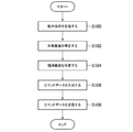
- FIG. 10 shows an example of processing executed when an operation instruction converted into text data is transmitted to the command data transmitting apparatus 10 together with a user ID.
- the control unit 11 executes the processing illustrated in FIG. 10 according to the program, the control unit 11 functions as the operation instruction receiving unit 110, the command data generation unit 120, and the command data transmission unit 130.
- the process shown in FIG. 10 will be described on the assumption that an operation instruction for instructing automatic performance of an electronic piano is received together with a user ID “U1”.
- the control unit 11 receives an operation instruction (S100). Then, the control unit 11 identifies the target device (S102). That is, the control unit 11 refers to the device table T1 of the user U1 and specifies the device 20 that is the target of the operation instruction. For example, since the electronic piano is the second device 20-2, the control unit 11 determines that the second device 20-2 is the target device.
- control unit 11 specifies related devices (S104). That is, the control unit 11 refers to the device table T1 of the user U1 and specifies another device 20 that needs to be operated when the target device performs an operation according to the operation instruction.
- the second device 20-2 is connected to the external input terminal of the first device 20-1, and the sound output from the second device 20-2 is emitted from the speaker via the first device 20-1. Therefore, the control unit 11 identifies the first device 20-1 as a related device.
- control unit 11 generates command data for controlling the target device and related devices (S106).
- the control unit 11 generates command data for causing the first device 20-1 to perform an operation that the first device 20-1 needs to perform when the second device 20-2 performs automatic performance.
- the control unit 11 command data (element data D41) for starting the first device 20-1 from the standby state, or command data for switching the input of the first device 20-1 to an external input. (Element data D43) is generated.
- event data D42 For data that needs to set a waiting time, such as command data for starting the first device 20-1, waiting time data (element data D42) is inserted. At this time, it is determined whether or not the first device 20-1 is in a standby state, and the first device 20-1 is activated from the standby state only when the first device 20-1 is in a standby state.
- Command data (element data D41) and waiting time data (element data D42) may be generated.
- control unit 11 generates command data for causing the second device 20-2 to perform automatic performance. Specifically, the control unit 11 starts command data for starting the second device 20-2 from a standby state, wait time data for setting a wait time, and starts an automatic performance on the second device 20-2. Command data (element data D44) is generated. At this time, it is determined whether or not the second device 20-2 is in the standby state, and the second device 20-2 is activated from the standby state only when the second device 20-2 is in the standby state. Command data and waiting time data may be generated.
- control unit 11 transmits command data (S108).
- control unit 11 refers to the device table T1 of the user U1 and determines whether or not the target device is in a state where data can be received via the Internet 6.
- the control unit 11 transmits command data for the target device to the target device via the MQTT server 70. That is, the control unit 11 publishes command data to a topic for transmission to the target device.
- the control unit 11 refers to the device table T1 of the user U1, identifies an alternative device of the target device, and obtains command data for the target device.
- the data is transmitted to the alternative device via the MQTT server 70. That is, the control unit 11 publishes command data to a topic for transmission to an alternative device.
- the control unit 11 compiles the command data for the target device and the command data for the related device into a single data (array command data) and publishes the above topic. To do. Even if the substitute device is the same as the related device, the control unit 11 individually does not combine the command data for the target device and the command data for the related device into one data (array command data). You may publish to the above topics.
- control unit 11 refers to the device table T1 of the user U1 and determines whether or not the related device is in a state where data can be received via the Internet 6.
- the control unit 11 transmits command data for the related device to the related device via the MQTT server 70. That is, the control unit 11 publishes the command data to a topic for transmission to the related device.
- the control unit 11 refers to the device table T1 of the user U1, specifies an alternative device for the related device, and obtains command data for the related device.
- the data is transmitted to the alternative device via the MQTT server 70. That is, the control unit 11 publishes command data to a topic for transmission to an alternative device.
- the control unit 11 compiles the command data for the target device and the command data for the related device into a single data (array command data) and publishes the topic. To do. Even if the alternative device is the same as the target device, the control unit 11 individually does not combine the command data for the target device and the command data for the related device into one data (array command data). You may publish to the above topics.
- FIG. 11 shows an example of processing executed when command data is transmitted to the device 20.
- the control unit 21 executes the processing shown in FIG. 11 according to the program, the control unit 21 functions as the command data reception unit 210 and the command transmission unit 220.
- the control unit 21 receives command data (S200). Then, the control unit 21 determines whether or not the received command data is array command data (S202). When the received command data is not array command data, that is, when only one command data is received, the control unit 21 acquires a command based on the items “ip” and “path” of the command data ( (S220), the command is transmitted (S222). That is, the control unit 21 accesses the URL acquired as a command. And the control part 21 complete
- the control unit 21 reads the head element data from the array command data (S204). Then, the control unit 21 determines whether or not the element data is command data (S206). When the element data is command data, the control unit 11 acquires a command based on the items “ip” and “path” of the command data (S208), and transmits the command (S210). That is, the control unit 21 accesses the URL generated as a command. Thereafter, the control unit 21 determines whether or not the next element data exists in the array command data (S212). When the next element data exists in the array command data, the control unit 21 reads the element data (S214) and executes step S206.
- the control unit 21 sets the waiting time based on the item “time” of the waiting time data (S216). Then, the control unit 21 monitors whether or not the waiting time has elapsed (S218). When the waiting time has elapsed, the control unit 21 executes Step S212.
- step S212 If it is determined in step S212 that the next element data does not exist in the array command data, the control unit 21 ends this process.
- the element data included in the array command data is either command data or standby time data (that is, “cmd” and “ However, the element data may be data other than command data and standby time data. That is, another process may be executed by setting items other than “cmd” and “time” in the item “type” of the element data.
- command data or array command data is received by the device 20 (that is, either “cmd” or “array” in the data item “type”). However, another process may be executed by setting data item “type” other than “cmd” and “array”.
- FIG. 12 shows an example of processing executed when the device information of the device 20 is acquired.
- the control units 11 and 21 execute the processing illustrated in FIG. 12 according to the program, the control unit 11 functions as the device information acquisition unit 140 and the control unit 21 functions as the device information transmission unit 230.
- the control unit 11 of the command data transmitting apparatus 10 generates command data for acquiring device information of the target device (S110). For example, command data D5 as shown in FIG. 8 is generated. Then, the control unit 11 transmits command data (S112). This process is executed in the same manner as in step S108.
- the control unit 21 of the device 20 acquires a command based on the items “ip” and “path” of the command data (S230), A command is transmitted (S232). That is, the control unit 21 accesses the URL acquired as a command.
- an HTTP request is transmitted to the target device, processing for returning device information is executed in the target device, and device information is returned as an HTTP response.
- the control unit 21 acquires device information (S234), and generates response data based on the device information (S236). For example, response data D6 as shown in FIG. 8 is generated.
- control part 21 transmits response data to the command data transmission apparatus 10 via the MQTT server 70 (S238). That is, the control unit 21 publishes response data to a topic for transmission to the command data transmission device 10. The published response data is transmitted to the command data transmitting apparatus 10.
- the control unit 11 acquires the device information of the target device from the response data (S114). For example, the acquired model information is registered in the database 60 (the device table T1 of the user U1).
- FIG. 13 shows an example of processing executed when a keyword command registration request is transmitted from the user terminal to the command data transmitting apparatus 10.
- the control unit 11 executes the process shown in FIG. 13 according to the program, the control unit 11 functions as the keyword command registration unit 170.
- the control unit 11 receives a keyword command registration request (S120). This registration request is received together with the user ID. This registration request includes keyword information set by the user and a plurality of command information selected by the user.
- the control unit 11 accesses the keyword command table T2 of the user, and registers a plurality of command information selected by the user in the keyword command table T2 in association with the keyword set by the user. (S122).
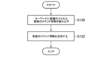
- FIG. 14 shows an example of processing executed when an operation instruction including a keyword is transmitted to the command data transmitting apparatus 10 together with the user ID.
- the control unit 11 refers to the keyword command table T2 of the user, and reads a plurality of command information associated with the keyword (S130). And the control part 11 acquires several command data based on these several command information, and transmits the said several command data (S132). This command data transmission process is executed in the same manner as in step S108.
- the device 20 to which a private IP address is set can be controlled via the Internet 6.
- the user can issue an operation instruction to the device 20 using a service (voice recognition service or the like) provided on the Internet 6.
- the command originally used for controlling the device 20 via the LAN 2 can be diverted when the device 20 is controlled via the Internet 6. As a result, there is no need to define commands separately.
- not all devices 20 need to be able to receive command data from the command data transmitting device 10. If at least one device 20 is in a state in which command data can be received from the command data transmission device 10, a command can be transmitted to another device 20 via the device 20 (alternative device).
- a plurality of command data for one device 20 and a plurality of command data for a plurality of devices 20 can be collectively transmitted as one data (packet) (see FIG. 7).
- a plurality of controls for one device 20 can be transmitted at a time, or a plurality of devices 20 can be controlled simultaneously.
- a plurality of command data can be transmitted / received quickly and the amount of packets can be reduced.
- the device control system 1 it is possible to adjust the time from the execution of a certain command to the execution of the next command by inserting the waiting time data. For example, when a command for starting the device 20 from a standby state is executed, the next command can be executed after the start of the device 20 is completed.
- the MQTT server 70 is provided with two topics, the first topic TP1 and the second topic TP2, and by using them separately, data transmission from the command data transmitting apparatus 10 to the device 20 can be performed. Data transmission from the device 20 to the command data transmission device 10 can be performed. As a result, for example, the command data transmission device 10 can acquire device information of the device 20.
- the first device 20-1, the second device 20-2, the third device 20-3, and the fourth device 20-4 are mainly AV receivers, electronic pianos, and television receivers.
- the device 20 to be controlled by the device control system 1 is not limited to this.
- the device 20 may be an audio device or an audio visual device other than an AV receiver, a television receiver, and a Blu-ray disc player, or an instrument other than an electronic piano (an instrument having a network function such as an electronic organ or a guitar). There may be.
- An audio device, an audiovisual device, or a musical instrument having a network communication function can be controlled by the device control system 1.
- the device 20 may be a device other than an audio device, an audiovisual device, and a musical instrument.
- a device having a network communication function can be a target of control by the device control system 1.
- the local area device that receives the command data from the command data transmission device 10 may be a device other than the device 20 that is the target of control by the device control system 1.
- the local area device may be a network device such as a router, a switch, or a wireless communication access point.
- the voice input device 30 may be connected to the Internet 6 and may not be connected to the same LAN 2 as the device 20.
- the user inputs the operation instruction of the device 20 to the voice input device 30, but the operation instruction may not be input by voice.
- the user may be able to input an operation instruction by selecting a button displayed on the terminal screen.
- the LAN 2 includes both a wired LAN and a wireless LAN, either one may be preferentially used according to the device 20 that is the command transmission destination.
- the command is transmitted via the LAN 2, but the command may be transmitted via a transmission means other than the LAN 2.
- the command may be transmitted via wireless communication other than the wireless LAN such as Bluetooth (registered trademark), or may be transmitted via a cable other than the LAN cable such as an HDMI cable.
- the “local area” is an area where communication is possible via wireless communication or a cable.
- the command is not limited to the format described above (see FIG. 2), and may be in another format.
- the command data is not limited to the format described above (see FIGS. 5, 7, and 8), and may be another format. That is, the command does not have to use the HTTP protocol.
- the command may be a command using Wake On LAN.
- the second device 20-2 is compatible with the Wake On LAN function, a magic packet (corresponding to a command) in which the MAC address of the second device 20-2 is repeated 16 times is sent to the first device 20-
- the second device 20-2 may be activated from the first device 20-1 by transmitting from 1 to the second device 20-2.
- the third device 20-3 or the fourth device 20-4 is activated from the first device 20-1.
- the device table T1 by providing a field indicating whether or not the Wake On LAN function is supported, it is possible to specify whether or not each device 20 supports the Wake On LAN function. do it.
- the third device 20-3 (television receiver) and the fourth device 20-4 (Blu-ray disc player) are connected to the first device 20-1 (AV receiver) via an HDMI cable. Therefore, a command for the third device 20-3 or the fourth device 20-4 may be transmitted via the HDMI cable. Specifically, a command for the third device 20-3 or the fourth device 20-4 may be transmitted using a CEC (Consumer Electronics Control) function defined in the HDMI standard.
- CEC Consumer Electronics Control
- command data for starting up the third device 20-3 is transmitted to the first device 20-1 (an alternative device of the third device 20-3: see FIG. 3).
- a command for starting the third device 20-3 is executed from the device 20-1 to the third device 20-3.
- an ON command (startup command) conforming to the CEC function may be transmitted via the HDMI cable. That is, the command transmission unit 220 of the first device 20-1 may output the command to the first HDMI terminal (HDMI1) to which the third device 20-3 is connected.
- the first device 20-1 to the third device 20-3 are similarly configured in accordance with the CEC function.
- the command may be transmitted via an HDMI cable.
- an operation instruction “X turn off TV” for turning off the television receiver (entering the standby state) is input to the audio input device 30, the first device 20-1 to the third device 20.
- an OFF command conforming to the CEC function may be transmitted via the HDMI cable.
- command data for causing the fourth device 20-4 (Blu-ray disc player) to reproduce the content is transmitted to the first device 20-1 (an alternative device of the fourth device 20-4: see FIG. 3).
- a command for causing the first device 20-1 to reproduce the content is executed from the fourth device 20-4.
- a PLAY command (playback command) conforming to the CEC function may be transmitted via the HDMI cable. That is, the command transmission unit 220 of the first device 20-1 may output the command to the fourth HDMI terminal (HDMI2) to which the fourth device 20-4 is connected.
- the first device 20-1 to the fourth device 20-4 are similarly configured.
- a command (ON, OFF, STOP, SKIP, etc.) conforming to the CEC function may be transmitted via the HDMI cable.
- the device table T1 may be provided with a “control type” field indicating a control type so that each device 20 can be specified via the LAN 2 or the HDMI cable. .
- a “control type” field indicating a control type so that each device 20 can be specified via the LAN 2 or the HDMI cable.
- these devices 20 can execute commands conforming to the CEC function. It is sufficient to be able to specify that it is controlled by.
- a command execution instruction in accordance with the CEC function may be added to a command originally used to control the device 20 via the LAN 2.
- the first device 20-1 when the first device 20-1 performs an operation of outputting an ON command conforming to the CEC function to the first HDMI terminal (HDMI1), “http://192.168.0.2. A command such as “/ ctrl? CEC_ON: HDMI1” may be executed.
- command data including a code transmitted from the remote controller via infrared communication may be generated and transmitted.
- an operation instruction “X watch TV” for viewing a television broadcast on a television receiver manufactured by X company is input to the audio input device 30.
- command data including a code transmitted when starting the third device 20-3 (television receiver) from the remote controller is the first device 20-1 (alternative device of the third device 20-3: FIG. 3) and a command for starting the third device 20-3 is executed from the first device 20-1 to the third device 20-3.
- the first device 20-1 may transmit the code via the LAN 2 or infrared communication.
- the second device 20-2 does not receive the command data (eg, command data D2) indicating the command for the second device 20-2, and the first device 20-1
- the second device 20-2 itself may receive the command data D2.
- two topics for the second device 20-2 are separated from the first topic TP1 and the second topic TP2 that are topics for the first device 20-1.
- the topic of the name based on the address is set in the MQTT server 70, and the second device 20-2 receives command data from the command data transmitting apparatus 10 via one of the topics, Device information or the like may be transmitted to the command data transmitting apparatus 10 via the other of them.
- the third device 20-3 or the fourth device 20-4 receives command data from the command data transmitting apparatus 10 via one of the topics, Device information or the like may be transmitted to the command data transmitting apparatus 10 via the other of them.
- Boot information indicating that the device 20 has been started and connected to the network, shutdown information that the device 20 has been shut down and the network connection has been disconnected, and an error has occurred in the network connection of the device 20 May be transmitted from the device 20 to the command processing system 50 (command data transmitting apparatus 10) via the MQTT server 70.
- the command processing system 50 may manage the state of the device 20 based on the above information.
- command data is transmitted by a method using the MQTT protocol, but other methods may be adopted.
- the command data may be registered in the server, and the command data registered in the server may be downloaded when the device 20 accesses the server.
Abstract
動作指示受付部(110)は、ローカルエリアに設置される機器に対する動作指示を受け付ける。コマンドデータ生成部(120)は、動作指示に応じた動作を行わせるために機器に対して送信すべきコマンドと、当該コマンドをローカルエリア内での伝送手段を介して機器に送信する際の宛先とを示すコマンドデータを生成する。コマンドデータ送信部(130)は、ローカルエリアに設置されるローカルエリア装置に対して、コマンドデータ生成部(120)によって生成されたコマンドデータを、ワイドエリアネットワークを介して送信する。
Description
本発明はコマンドデータ送信装置、ローカルエリア装置、機器制御システム、コマンドデータ送信装置の制御方法、ローカルエリア装置の制御方法、機器制御方法、及びプログラムに関する。
ローカルエリアネットワーク(LAN)を介して送信されるコマンドを受信して当該コマンドに対応する動作を行う機器が知られている(特許文献1)。このような機器に関してはLANを介して制御できる。
一般的に、上記のような機器に対してはローカルエリア内でのみ有効なプライベートIPアドレスが設定されることが多い。プライベートIPアドレスが設定された機器に対しては、インターネット(ワイドエリアネットワーク)を介してコマンドを直接送信できないため、上記コマンドを使用して、インターネットを介して機器を制御することができなかった。
本発明は上記課題に鑑みてなされたものであって、その目的は、ローカルエリアで使用されるコマンドを使用しつつ、インターネット等のワイドエリアネットワークを介して機器を制御することが可能なコマンドデータ送信装置、ローカルエリア装置、機器制御システム、コマンドデータ送信装置の制御方法、ローカルエリア装置の制御方法、機器制御方法、及びプログラムを提供することにある。
上記課題を解決するために、本発明に係るコマンドデータ送信装置は、ローカルエリアに設置される機器に対する動作指示を受け付ける動作指示受付手段と、前記動作指示に応じた動作を行わせるために前記機器に対して送信すべきコマンドと、当該コマンドを前記ローカルエリア内での伝送手段を介して前記機器に送信する際の宛先とを示すコマンドデータを生成するコマンドデータ生成手段と、前記ローカルエリアに設置されるローカルエリア装置に対して、前記コマンドデータ生成手段によって生成されたコマンドデータを、ワイドエリアネットワークを介して送信するコマンドデータ送信手段と、を含む。
また、本発明に係るローカルエリア装置は、ローカルエリアでの伝送手段を介してコマンドを送信すべき宛先と、前記伝送手段を介して当該宛先に送信すべきコマンドとを示すコマンドデータをワイドエリアネットワークを介して受信するコマンドデータ受信手段と、前記コマンドデータに基づいて、前記伝送手段を介して前記宛先に前記コマンドを送信するコマンド送信手段と、を含む。
また、本発明に係る機器制御システムは、ワイドエリアネットワークを介してコマンドデータを送信可能なコマンドデータ送信装置であって、ローカルエリアに設置される機器に対する動作指示を受け付ける動作指示受付手段と、前記動作指示に基づいて、当該動作指示に応じた動作を行わせるために前記機器に対して送信すべきコマンドと、当該コマンドを前記ローカルエリア内での伝送手段を介して前記機器に送信する際の宛先とを示すコマンドデータを生成するコマンドデータ生成手段と、前記ローカルエリアに設置されるローカルエリア装置に対して、前記コマンドデータ生成手段によって生成されたコマンドデータを、ワイドエリアネットワークを介して送信するコマンドデータ送信手段と、を含むコマンドデータ送信装置と、前記ローカルエリア装置であって、前記コマンドデータを前記ワイドエリアネットワークを介して受信するコマンドデータ受信手段と、前記コマンドデータに基づいて、前記伝送手段を介して前記宛先に前記コマンドを送信するコマンド送信手段と、を含む前記ローカルエリア装置と、を含む。
また、本発明に係るコマンドデータ送信装置の制御方法は、ローカルエリアに設置される機器に対する動作指示を受け付ける動作指示受付ステップと、前記動作指示に基づいて、当該動作指示に応じた動作を行わせるために前記機器に対して送信すべきコマンドと、当該コマンドを前記ローカルエリア内での伝送手段を介して前記機器に送信する際の宛先とを示すコマンドデータを生成するコマンドデータ生成ステップと、前記ローカルエリアに設置されるローカルエリア装置に対して、前記コマンドデータ生成ステップによって生成されたコマンドデータを、ワイドエリアネットワークを介して送信するコマンドデータ送信ステップと、を含む。
また、本発明に係るローカルエリア装置の制御方法は、ローカルエリアでの伝送手段を介してコマンドを送信すべき宛先と、前記伝送手段を介して当該宛先に送信すべきコマンドとを示すコマンドデータをワイドエリアネットワークを介して受信するコマンドデータ受信ステップと、前記コマンドデータに基づいて、前記伝送手段を介して前記宛先に前記コマンドを送信するコマンド送信ステップと、を含む。
また、本発明に係るローカルエリア装置の制御方法は、コマンドデータ送信装置が、ローカルエリアに設置される機器に対する動作指示を受け付ける動作指示受付ステップと、前記コマンドデータ送信装置が、前記動作指示に基づいて、当該動作指示に応じた動作を行わせるために前記機器に対して送信すべきコマンドと、当該コマンドを前記ローカルエリア内での伝送手段を介して前記機器に送信する際の宛先とを示すコマンドデータを生成するコマンドデータ生成ステップと、前記コマンドデータ送信装置が、前記ローカルエリアに設置されるローカルエリア装置に対して、前記コマンドデータ生成手段によって生成されたコマンドデータを、ワイドエリアネットワークを介して送信するコマンドデータ送信ステップと、前記ローカルエリア装置が、前記コマンドデータを前記ワイドエリアネットワークを介して受信するコマンドデータ受信ステップと、前記ローカルエリア装置が、前記コマンドデータに基づいて、前記伝送手段を介して前記宛先に前記コマンドを送信するコマンド送信ステップと、を含む。
また、本発明に係るプログラムは、ローカルエリアに設置される機器に対する動作指示を受け付ける動作指示受付手段、前記動作指示に基づいて、当該動作指示に応じた動作を行わせるために前記機器に対して送信すべきコマンドと、当該コマンドを前記ローカルエリア内での伝送手段を介して前記機器に送信する際の宛先とを示すコマンドデータを生成するコマンドデータ生成手段、及び、前記ローカルエリアに設置されるローカルエリア装置に対して、前記コマンドデータ生成手段によって生成されたコマンドデータを、ワイドエリアネットワークを介して送信するコマンドデータ送信手段、としてコンピュータとして機能させるためのプログラムである。また、本発明に係る情報記憶媒体は、上記プログラムを記録したコンピュータ読み取り可能な情報記憶媒体である。
また、本発明に係るプログラムは、ローカルエリアでの伝送手段を介してコマンドを送信すべき宛先と、前記伝送手段を介して当該宛先に送信すべきコマンドとを示すコマンドデータをワイドエリアネットワークを介して受信するコマンドデータ受信手段、及び、前記コマンドデータに基づいて、前記伝送手段を介して前記宛先に前記コマンドを送信するコマンド送信手段、としてコンピュータを機能させるためのプログラムである。また、本発明に係る情報記憶媒体は、上記プログラムを記録したコンピュータ読み取り可能な情報記憶媒体である。
本発明によれば、ローカルエリアで使用されるコマンドを使用しつつ、インターネット等のワイドエリアネットワークを介して機器を制御することが可能になる。
以下、本発明の実施形態の例を図面に基づいて説明する。
[1.システム構成]図1は、本発明の実施形態に係る機器制御システムの構成を示す。図1に示すように、機器制御システム1は、第1機器20-1、第2機器20-2、第3機器20-3、第4機器20-4、音声入力装置30、音声認識装置40、及びコマンド処理システム50を含む。以下では、第1機器20-1、第2機器20-2、第3機器20-3、及び第4機器20-4を総称して「機器20」と記載する場合がある。
機器20及び音声入力装置30はローカルエリアに設置され、LAN2に接続される。LAN2は有線LANであってもよいし、無線LANであってもよい。LAN2はルータ4を介してインターネット6(ワイドエリアネットワーク)に接続される。音声認識装置40及びコマンド処理システム50はローカルエリア外に設置される。すなわち、機器20及び音声入力装置30から見て、音声認識装置40及びコマンド処理システム50はインターネット6側に設置される。なお、「ローカルエリア」とは、LAN2を介した通信が可能な限られた範囲のエリアである。一方、「ワイドエリア」とは、ローカルエリア外も含むエリアであり、インターネット6を介した通信が可能な範囲のエリアである。
機器20は機器制御システム1による制御の対象となる機器である。図1では、4台の機器20のみが示されているが、5台以上の機器20が含まれていてもよいし、3台以下の機器20のみが含まれていてもよい。
例えば、機器20はオーディオ機器又はオーディオビジュアル機器である。具体的には、機器20は、AVレシーバ、AVアンプ、スピーカ、光ディスク再生機器(ブルーレイディスク(登録商標)プレーヤ又はDVD(登録商標)プレーヤ等)、又はテレビジョン受像機である。また例えば、機器20は楽器(電子楽器又は電気楽器等)であってもよい。なお、機器20はこれら以外の機器であってもよい。
以下では、第1機器20-1がAVレシーバであり、第2機器20-2が自動演奏機能(データに基づいて鍵盤やペダルの動きを再現して自動的に演奏を行う機能)を備えた電子ピアノであり、第3機器20-3がテレビジョン受像機であり、第4機器20-4がブルーレイディスクプレーヤである例を想定する。第2機器20-2はオーディオケーブルを介して第1機器20-1の外部入力端子に接続され、第3機器20-3はHDMI(High-Definition Multimedia Interface:登録商標)ケーブルを介して第1機器20-1の第1のHDMI端子(HDMI1)に接続され、第4機器20-4はHDMIケーブルを介して第1機器20-1の第2のHDMI端子(HDMI2)に接続されている。また、第1機器20-1のMACアドレスは「aa:bb:cc:dd:ee:11」であり、プライベートIPアドレス「192.168.0.2」が第1機器20-1に対して設定されている。第2機器20-2のMACアドレスは「aa:bb:cc:dd:ee:22」であり、プライベートIPアドレス「192.168.0.3」が第2機器20-2に対して設定されている。第3機器20-3のMACアドレスは「aa:bb:cc:dd:ee:33」であり、プライベートIPアドレス「192.168.0.4」が第3機器20-3に対して設定されている。第4機器20-4のMACアドレスは「aa:bb:cc:dd:ee:44」であり、プライベートIPアドレス「192.168.0.5」が第4機器20-4に対して設定されている。
図1に示すように、第1機器20-1は制御部21、記憶部22、及び通信部23を含む。制御部21は少なくとも一つのマイクロプロセッサ(CPU)を含み、記憶部22に記憶されたプログラムに従って処理を実行する。記憶部22は、主記憶部(例えばRAM)及び補助記憶部(例えば、不揮発性の半導体メモリ、ハードディスクドライブ、又はソリッドステートドライブ)を含む。記憶部22はプログラムやデータを記憶するためのものである。通信部23は他の装置との間でデータを送受信するためのものである。図1では省略されているが、第2機器20-2、第3機器20-3、及び第4機器20-4も制御部21、記憶部22、及び通信部23を含む。
なお、機器20は、情報記憶媒体(例えば光ディスク又はメモリカード等)に記憶されたプログラムやデータを読み取るための構成要素(例えば光ディスクドライブ又はメモリーカードスロット等)を備えてもよい。そして、プログラムが情報記憶媒体を介して機器20に供給されてもよい。プログラムはインターネット6を介して機器20に供給されてもよい。
機器20は、LAN2(ローカルエリア内での伝送手段の一例)を介して送信されるコマンドを受信して当該コマンドに対応する動作を行う。このため、LAN2を介して機器20を制御できる。すなわち、スマートフォン又はタブレット型コンピュータ等の端末からLAN2を介してコマンドを機器20に送信することによって、当該コマンドに応じた動作を機器20に行わせることができる。
図2はコマンドの例を示す。図2に示すコマンドC1~C4は第1機器20-1(AVレシーバ)に対するコマンドの例であり、コマンドC5~C7は第2機器20-2(電子ピアノ)に対するコマンドの例である。
図2に示すコマンドはHTTPプロトコルを使用したものになっており、コマンドとしてURLが設定されている。図2に示す例の場合、コマンドがHTTPリクエストの形で第1機器20-1又は第2機器20-2に対して送信される。第1機器20-1又は第2機器20-2ではHTTPデーモンが起動されており、HTTPデーモンによってHTTPリクエストが受け付けられ、当該HTTPリクエストに応じた処理が実行される。そして、その処理結果を示すHTTPレスポンスがコマンドの送信元に返信される。なお、第3機器20-3及び第4機器20-4に対しても、HTTPプロトコルを使用したコマンドを送信することが可能である。
コマンドC1は第1機器20-1をスタンバイ状態(非起動状態)から起動するコマンドである。「スタンバイ状態」とは消費電力が通常状態(起動状態)よりも低減された状態である。すなわち、スタンバイ状態は完全に電源がオフになった状態ではなく、スタンバイ状態でもネットワーク通信機能等は有効になっており、コマンドデータを受信したり、コマンドを実行(送信)したり、コマンドを受け付けたりすることが可能である。
コマンドC2は第1機器20-1の入力を外部入力に切り替えるコマンドである。例えば、第1機器20-1(AVレシーバ)は複数の入力端子(例えばHDMI端子や外部入力端子等)を備え、第2機器20-2を含む複数の機器20がそれら複数の入力端子に接続される。また、第1機器20-1にはスピーカ(放音手段の一例)が接続され、第1機器20-1はいずれかの入力端子から入力される音声信号をスピーカから放音させる。コマンドC2は、スピーカに供給する音声信号を外部入力端子から入力される音声信号に切り替えるコマンドである。
コマンドC3は出力音量を設定するコマンドである。コマンドC4は第1機器20-1の機器情報を要求するコマンドである。コマンドC4が実行された場合、第1機器20-1の機器情報(機種名又は現在状態情報等)がコマンドC4の送信元に返信される。
コマンドC5は第2機器20-2をスタンバイ状態から起動するコマンドである。コマンドC6は第2機器20-2(電子ピアノ)の自動演奏を開始させるコマンドである。コマンドC7は第2機器20-2の機器情報を要求するコマンドである。なお、第2機器20-2と第1機器20-1とでコマンドの形式は同じであってもよいし、異なっていてもよい。第1機器20-1、第2機器20-2、第3機器20-3、及び第4機器20-4の間でもコマンドの形式は同じであってもよいし、異なっていてもよい。
音声入力装置30はマイクロフォンを含み、音声入力を受け付ける。本実施形態では、ユーザが機器20への動作指示を音声入力するために音声入力装置30が使用される。例えば、X社製の電子ピアノに自動演奏させたい場合、ユーザは「X piano play」等を音声入力装置30に入力する。また例えば、居間に設置されているX社製のオーディオシステムに音楽を再生させたい場合、ユーザは「X play in living room」等を音声入力装置30に入力する。
音声入力装置30に入力された音声(動作指示)を示す音声データはユーザIDとともにインターネット6を介して音声認識装置40に送信される。音声認識装置40は例えばサーバコンピュータによって実現される。音声認識装置40は音声認識処理を実行することによって、音声データを、プログラム(コマンド処理システム50)によって理解しやす形式のデータに変換する。例えば、音声データを所定形式のテキストデータに変換する。そして、テキストデータに変換された動作指示はユーザIDとともにコマンド処理システム50に送信される。なお、ユーザIDは、音声データがコマンド処理システム50に送信されるまでの間に、いずれかのインターネット側の装置(処理)によって付与されてもよい。
なお、機器20の製造元ごとに異なるコマンド処理システム50が用意されている場合であれば、X社製の機器20に対する動作指示は、X社製の機器20用のコマンド処理システム50に送信される。また、コマンドの形式ごとに異なるコマンド処理システム50が用意されている場合であれば、機器20に対する動作指示は、当該機器20で採用されているコマンドの形式用のコマンド処理システム50に送信される。
図1に示すように、コマンド処理システム50は、コマンドデータ送信装置10、データベース60、及びMQTT(Message Queueing Telemetry Transport)サーバ70を含む。
データベース60は各種データを記憶する。例えば、データベース60は各ユーザの所有している機器20の情報を記憶する。図3はデータベース60に記憶される機器テーブルの一例を示す。機器テーブルT1はユーザごとに(ユーザIDと関連付けて)記憶される。なお、コマンド処理システム50(データベース60)で使用されるユーザIDは、音声入力装置30及び音声認識装置40で使用されるユーザIDと異なっていてもよいし、同じであってもよい。ただし、これらのユーザIDが異なる場合には、それらのユーザIDを変換するための対応関係データがコマンド処理システム50又は音声認識装置40に記憶されている必要がある。
図3に示すように、機器テーブルT1は「ID」、「名称」、「機種」、「MACアドレス」、「IPアドレス」、「コマンド種類」、「端子」、「音量範囲」、「接続先」、「受信可否」、「代替機器」フィールドを含む。
「ID」フィールドは、ユーザの所有している各機器20を一意に識別する情報を示す。図3では、第1機器20-1が機器ID「1」に相当し、第2機器20-2が機器ID「2」に相当する。
「名称」フィールドは機器20の名称を示す。この名称はユーザが動作指示の対象の機器20を指定するために使用される。名称としては、ユーザによって設定された任意の名称が使用されるようにしてもよいし、機器20の製造元等によって設定された名称が使用されるようにしてもよい。「機種」フィールドは機器20の機種名(型名)を示す。
「MACアドレス」及び「IPアドレス」フィールドは、機器20が備えている有線又は無線ネットワークインタフェースカードに対して設定されたMACアドレス及びIPアドレスを示す。「コマンド種類」フィールドは、機器20で使用されているコマンドの種類(体系)を示す。なお、機種ごとにコマンドの種類が定められる場合には、機種とコマンドの種類とを関連付けてなるテーブルを別途設けておき、その代わりに、「コマンド種類」フィールドを機器テーブルT1に設けないようにしてもよい。「端子」フィールドは、機器20が備えている入力端子のリストを示す。「音量範囲」フィールドは、機器20で設定可能な音量の範囲を示す。「接続先」フィールドは、機器20が他の機器20の入力端子に接続されて、機器20から出力される音声が他の機器20に入力される場合に、機器20が接続された他の機器20の入力端子を示す。
「受信可否」フィールドは、インターネット6を介してコマンドデータを受信可能であるか否かを示す。コマンドデータについては後述する。例えば、「0」又は「1」が「受信可否」フィールドに登録される。「0」は、インターネット6を介してコマンドデータを受信できないことを示し、「1」は、インターネット6を介してコマンドデータを受信できることを示す。「代替機器」フィールドは、機器20がインターネット6を介してコマンドデータを受信できない場合に、当該機器20の代わりにコマンドデータを受信する機器20(代替機器)を示す。
例えば、機器テーブルT1は各ユーザによって登録される。ユーザは端末からコマンドデータ送信装置10にアクセスすることによって、自らの所有する機器20の情報を機器テーブルT1に登録できる。機器20をLAN2に接続して起動した際に、機器20の情報がユーザIDとともにコマンド処理システム50(コマンドデータ送信装置10)に送信されて機器テーブルT1に登録されるようにしてもよい。
なお、データベース60には機器テーブルT1以外のデータも記憶される。例えば、動作指示とコマンドとの対応関係を示すデータ(言い換えれば、動作指示をコマンドに変換するためのデータ)がデータベース60に記憶される。このデータはコマンドの種類(体系)ごとに記憶される。
コマンドデータ送信装置10は例えばサーバコンピュータによって実現される。図1に示すように、コマンドデータ送信装置10は制御部11、記憶部12、及び通信部13を含む。制御部11、記憶部12、及び通信部13は制御部21、記憶部22、及び通信部23と同様である。なお、コマンドデータ送信装置10は、情報記憶媒体(例えば光ディスク又はメモリカード等)に記憶されたプログラムやデータを読み取るための構成要素(例えば光ディスクドライブ又はメモリーカードスロット等)を備えてもよい。そして、プログラムが情報記憶媒体を介してコマンドデータ送信装置10に供給されてもよい。プログラムはインターネット6を介してコマンドデータ送信装置10に供給されてもよい。
コマンドデータ送信装置10はデータベース60にアクセス可能である。コマンドデータ送信装置10とデータベース60とは一つのサーバコンピュータによって実現されてもよいし、別のサーバコンピュータによって実現されてもよい。
コマンドデータ送信装置10は、機器20に対する動作指示を受け付け、当該動作指示に基づいてコマンドデータを生成し、当該コマンドデータを当該機器20又は他の機器20(代替機器)に送信する。後述するように、コマンドデータはMQTTサーバ70を介して機器20又は他の機器20(代替機器)に送信される。MQTTサーバ70は、MQTTプロトコルを使用してデータを送受信するためのものである。コマンドデータ送信装置10とMQTTサーバ70とは一つのサーバコンピュータによって実現されてもよいし、別のサーバコンピュータによって実現されてもよい。
[2.機能ブロック]図4は、コマンドデータ送信装置10及び機器20で実現される機能ブロックの一例を示す。
図4に示すように、コマンドデータ送信装置10は動作指示受付部110、コマンドデータ生成部120、コマンドデータ送信部130、機器情報取得部140、判定部150、通知部160、及びキーワードコマンド登録部170を含む。これらの機能ブロックは例えば制御部11によって実現される。
また図4に示すように、機器20はコマンドデータ受信部210、コマンド送信部220、及び機器情報送信部230を含む。これらの機能ブロックは例えば制御部21によって実現される。
[2-1]まず、動作指示受付部110、コマンドデータ生成部120、コマンドデータ送信部130、コマンドデータ受信部210、及びコマンド送信部220について説明する。
動作指示受付部110は、第1機器20-1又は第2機器20-2に対する動作指示を受け付ける。例えば、動作指示受付部110は、音声認識装置40によってテキストデータ等のプログラムにとって理解しやすい形式のデータに変換された動作指示を音声認識装置40から受信する。
コマンドデータ生成部120は、動作指示に応じた動作を行わせるために第1機器20-1又は第2機器20-2に対して送信すべきコマンドと、当該コマンドをLAN2を介して第1機器20-1又は第2機器20-2に送信する際の宛先とを示すコマンドデータを生成する。
図5はコマンドデータの例を示す。図5に示すコマンドデータD1は、第1機器20-1をスタンバイ状態から起動する旨の動作指示が受け付けられた場合に生成されるコマンドデータの一例を示す。すなわち、コマンドデータD1は、図2に示したコマンドC1を第1機器20-1に対して実行したい場合に生成されるコマンドデータの一例を示す。
コマンドデータD1は項目「type」,「id」,「command」を含む。項目「type」はデータの種別を示す。図5に示す例では「cmd」が項目「type」に設定されている。これはデータがコマンドデータであることを示している。項目「id」はデータ(コマンドデータ)を一意に識別する識別情報を示す。項目「command」はコマンドデータの内容を示す。項目「command」は項目「ip」,「path」,「method」を含む。項目「ip」はコマンドの宛先を示す。第1機器20-1のIPアドレスが項目「ip」に設定されている。項目「path」はコマンド本体に相当する。項目「ip」はコマンドC1のうちのIPアドレス部分に相当し、項目「path」はコマンドC1のうちのIPアドレス以降の部分に相当する。項目「method」は、使用されるHTTPプロトコルのメソッドを示す。
図5に示すコマンドデータD2は、第2機器20-2をスタンバイ状態から起動する旨の動作指示が受け付けられた場合に生成されるデータの一例を示す。すなわち、コマンドデータD2は、図2に示したコマンドC5を第2機器20-2に対して実行したい場合に生成されるコマンドデータの一例を示す。コマンドデータD1と同様、コマンドデータD2も項目「type」,「id」,「command」を含む。コマンドデータD2では、第2機器20-2のIPアドレスが項目「ip」に設定されている。コマンドデータD2では、項目「ip」がコマンドC5のうちのIPアドレス部分に相当し、項目「path」はコマンドC5のうちのIPアドレス以降の部分に相当する。
なお、コマンドデータD1,D2では、HTTPプロトコルのGETメソッドを使用する場合について示していたが、POSTメソッドを使用するようにしてもよい。図5のコマンドデータD3に示すように、POSTメソッドを使用する場合には、POSTメソッドによって送信される内容を示す項目「body」を含む。なお、HTTPヘッダ情報によって送信される内容を示す項目「headers」をコマンドデータに含めてもよい。例えば、“headers”:[“X-HEADER1:INFO1”,“X-HEADER2:INFO2”]のような項目「headers」をコマンドデータに含め、コマンド送信時に当該内容をHTTPヘッダに追加して送信するようにしてもよい。
コマンドデータ送信部130は、コマンドデータ生成部120によって生成されたコマンドデータをインターネット6を介してローカルエリア装置に送信する。「ローカルエリア装置」とは、ローカルエリアに設置される装置であり、インターネット6を介してデータを受信可能な装置であり、LAN2を介してコマンドを宛先に送信可能な装置である。
例えば、第1機器20-1はインターネット6を介して送信されるデータを受信可能である(図3参照)。このため、第1機器20-1に対するコマンドを示すコマンドデータが生成された場合、コマンドデータ送信部130は当該コマンドデータをインターネット6を介して第1機器20-1(ローカルエリア装置)に送信する。
一方、第2機器20-2はインターネット6を介して送信されるデータを受信可能でない(図3参照)。このため、第2機器20-2に対するコマンドを示すコマンドデータがて生成された場合、コマンドデータ送信部130は当該コマンドデータを、インターネット6を介して、代替機器として登録されている第1機器20-1(ローカルエリア装置)に送信する。
コマンドデータはMQTTプロトコルを使用してローカルエリア装置に送信される。すなわち、コマンドデータ送信部130はMQTTサーバ70を介してコマンドデータをローカルエリア装置に送信する。図6はMQTTサーバ70について説明するための図である。なお、図6ではローカルエリア装置が第1機器20-1である場合を想定している。
図6に示すように、MQTTサーバ70には第1トピックTP1が設定される。第1トピックTP1は、コマンドデータ送信装置10から第1機器20-1へデータを送信するためのトピックである。第1トピックTP1の識別情報(名称)は第1機器20-1の識別情報に基づいて設定される。例えば、第1機器20-1の識別情報であるMACアドレスと、第1機器20-1へデータを送信するためのトピックであることを示す「SEND」の文字列とを組み合わせてなる「aabbccddee11_SEND」という識別情報が第1トピックTP1に対して設定される。
また図6に示すように、MQTTサーバ70には第2トピックTP2も設定される。第2トピックTP2は、第1機器20-1からコマンドデータ送信装置10へデータ(応答)を送信するためのトピックである。第2トピックTP2の識別情報(名称)も第1機器20-1の識別情報に基づいて設定される。例えば、第1機器20-1の識別情報であるMACアドレスと、コマンドデータ送信装置10へ応答を送信するためのトピックであることを示す「RESPOND」の文字列とを組み合わせてなる「aabbccddee11_RESPOND」という識別情報が第2トピックTP2に対して設定される。
コマンドデータを第1機器20-1に送信する場合、コマンドデータ送信部130はコマンドデータを第1トピックTP1にパブリッシュする。第1トピックTP1には第1機器20-1がサブスクライバとして登録されており、第1トピックTP1にパブリッシュされたコマンドデータは、第1トピックTP1をサブスクライブしている第1機器20-1にパブリッシュされる。すなわち、第1トピックTP1にパブリッシュされたコマンドデータは第1機器20-1に送信される。このようにして、コマンドデータは第1トピックTP1を介して第1機器20-1に送信される。なお、第2トピックTP2を設ける意義については後述する。
ここで、電子ピアノに自動演奏が行わせる旨の動作指示が動作指示受付部110によって受け付けられた場合を想定する。なお、当該動作指示はユーザU1(ユーザIDが「U1」であるユーザ)によってなされたものとする。
この場合、コマンドデータ生成部120はユーザU1の機器テーブルT1を参照し、電子ピアノが第2機器20-2であることを特定し、第2機器20-2の情報を取得する。
コマンドデータ生成部120は、第2機器20-2に自動演奏を行わせる際に動作させる必要のある他の機器20を特定する。第2機器20-2は第1機器20-1の外部入力端子に接続され、第2機器20-2から出力される音声が第1機器20-1を介してスピーカから放音されるため(「接続先」フィールド参照)、コマンドデータ生成部120は、第2機器20-2に自動演奏を行わせる際に動作させる必要のある他の機器20として第1機器20-1を特定する。このため、コマンドデータ生成部120は、第2機器20-2に対するコマンドを示すコマンドデータだけでなく、第1機器20-1に対するコマンドを示すコマンドデータも生成する。
また、コマンドデータ生成部120は、第1機器20-1及び第2機器20-2で使用されるコマンドの種類(体系)を把握し(「コマンド種類」又は「機種」フィールド参照)、どのような種類(体系)のコマンドのコマンドデータを生成すればよいのかを把握する。さらに、コマンドデータ生成部120は、第2機器20-2がインターネット6を介してデータを受信できないことや、第2機器20-2の代替機器が第1機器20-1であることを把握する(「受信可否」及び「代替機器」フィールド参照)。
そして、コマンドデータ生成部120は、第1機器20-1に対するコマンドを示すコマンドデータと、第2機器20-2に対するコマンドを示すコマンドデータとを一つにまとめたデータを生成し、コマンドデータ送信部130は当該データをMQTTサーバ70を介して第1機器20-1に送信する。なお以下では、複数のコマンドデータを一つにまとめたデータのことを「アレイコマンドデータ」と呼ぶ。
図7はアレイコマンドデータの一例を示す。図7に示すアレイコマンドデータD4は複数のコマンドデータを含む。図7に示すアレイコマンドデータD4では項目「type」に「array」が設定されている。これはこのデータがアレイコマンドデータであり、複数のコマンドデータを含むことを示す。この場合、複数のコマンドデータを格納するための項目「array」がアレイコマンドデータD4に含まれる。
図7に示す例では、要素データD41、要素データD42、要素データD43、及び要素データD44が項目「array」に含まれている。要素データD41は第1機器20-1をスタンバイ状態から起動するためのコマンドデータである。先述の通り、第2機器20-2は第1機器20-1に接続されているため、第2機器20-2の自動演奏をスピーカから放音するためには第1機器20-1をスタンバイ状態から起動する必要がある。このため、第1機器20-1を起動するためのコマンドデータが要素データD41として含まれる。要素データD41は図5に示すコマンドデータD1と同様である。
要素データD42は待ち時間(ディレイ時間)を設けることを示す待ち時間データである。第1機器20-1の起動には時間がかかるため、第1機器20-1を起動した後で次のコマンドを第1機器20-1に対して実行する場合には、第1機器20-1の起動が完了するのを待って次のコマンドを実行する必要がある。このため、第1機器20-1の起動が完了するのを待つべく、待ち時間データが要素データD42として含まれる。要素データD42では項目「type」に「delay」が設定されている。これは要素データD42が待ち時間データであることを示す。要素データD42は項目「time」を含む。項目「time」は待ち時間を示す。図7に示す例では500ミリ秒が項目「time」に設定されている。なお、500ミリ秒よりも長い時間(例えば2秒)を待ち時間として設定してもよいし、500ミリ秒よりも短い時間を待ち時間として設定してもよい。第1機器20-1の起動に要する時間を考慮して待ち時間を設定すればよい。
要素データD43は第1機器20-1の入力を外部入力に切り替えるためのコマンドデータである。第2機器20-2の自動演奏をスピーカから放音するためには、第1機器20-1の入力を、第2機器20-2が接続された外部入力に切り替える必要がある。このため、第1機器20-1の入力を外部入力に切り替えるためのコマンドデータが要素データD43として含まれる。要素データD43では、図2に示したコマンドC2のうちのIPアドレス部分が項目「ip」に設定され、コマンドC2のうちのIPアドレス以降の部分が項目「path」に設定されている。
要素データD44は、第2機器20-2に自動演奏を開始させるためのコマンドデータである。要素データD44では、図2に示したコマンドC6のうちのIPアドレス部分が項目「ip」に設定され、コマンドC6のうちのIPアドレス以降の部分が項目「path」に設定されている。要素データD44を送信する際には、自動演奏する楽曲を指定するためのコマンドデータも一緒に送信してもよい。このコマンドデータを送信しない場合には、所定の楽曲を自動演奏の対象として自動的に設定すればよい。例えば、お気に入り登録された楽曲のうちのいずれかや、過去に自動演奏されたことのある楽曲のいずれかを自動演奏の対象として自動的に設定すればよい。
図7では省略しているが、実際には、要素データD43と要素データD44との間には、第2機器20-2をスタンバイ状態から起動するためのコマンドデータや、第2機器20-2の起動が完了するの待つための待ち時間データが要素データとして含まれる。
コマンドデータ送信部130はアレイコマンドデータD4をMQTTサーバ70の第1トピックTP1にパブリッシュする。先述の通り、第1トピックTP1にパブリッシュされたアレイコマンドデータD4は、第1トピックTP1にサブスクライブした第1機器20-1にパブリッシュされる。すなわち、アレイコマンドデータD4が第1機器20-1に送信される。
コマンドデータ受信部210はコマンドデータをインターネット6を介して受信する。コマンド送信部220は、コマンドデータに基づいて、LAN2を介して宛先にコマンドを送信する。
ここで、アレイコマンドデータD4が第1機器20-1のコマンドデータ受信部210によって受信された場合を想定する。この場合、コマンド送信部220はアレイコマンドデータD4に含まれるコマンドデータを先頭から順番に実行していく。
まず、コマンド送信部220は要素データD41に基づいてコマンドを第1機器20-1に対して実行する。すなわち、要素データD41の項目「ip」及び「path」に基づき、コマンド送信部220は図2に示したコマンドC1を取得する。そして、コマンド送信部220はコマンドC1として設定されたURLにアクセスする。この場合、HTTPリクエストが第1機器20-1に送信される。要素データD41の項目「ip」には第1機器20-1自身のIPアドレスが設定されているため、第1機器20-1自身のHTTPデーモンに対してHTTPリクエストが送信される。その結果、第1機器20-1がスタンバイ状態から起動される。
その後、要素データD42に基づき、コマンド送信部220は待ち時間(500ミリ秒)が経過するのを待つ。待ち時間が経過したら、コマンド送信部220は要素データD43に基づいてコマンドを第1機器20-1に対して実行する。すなわち、要素データD43の項目「ip」及び「path」に基づき、コマンド送信部220は図2に示したコマンドC2を取得する。そして、コマンド送信部220はコマンドC2として設定されたURLにアクセスする。この場合、第1機器20-1の入力が外部入力に切り替えられる。
さらに、その後、図7で省略されているコマンドデータに基づき、コマンド送信部220は図2に示したコマンドC5を取得し、コマンドC5として設定されたURLにアクセスする。この場合、第2機器20-2がスタンバイ状態から起動される。また、図7で省略されている待ち時間データに基づき、コマンド送信部220は待ち時間(例えば500ミリ秒)が経過するのを待つ。待ち時間が経過したら、コマンド送信部220は要素データD44に基づいてコマンドを第2機器20-2に対して実行する。すなわち、要素データD44の項目「ip」及び「path」に基づき、コマンド送信部220は図2に示したコマンドC6を取得する。そして、コマンド送信部220はコマンドC6として設定されたURLにアクセスする。この場合、HTTPリクエストが第2機器20-2に送信され、その結果、第2機器20-2による自動演奏が開始される。
[2-2]次に、機器情報取得部140及び機器情報送信部230について説明する。
機器情報取得部140は機器20の機器情報を取得する。機器情報取得部140は、機器20に対して当該機器20の機器情報を返信させるためのコマンドと、当該コマンドをLAN2を介して機器20に送信する際の宛先とを示すコマンドデータを生成し、当該コマンドデータをインターネット6を介してローカルエリア装置に送信する。なお、このコマンドデータの生成及び送信もコマンドデータ生成部120及びコマンドデータ送信部130を介して実行されてもよい。
例えば、第1機器20-1の機器情報を取得する場合、機器情報取得部140は図8に示すコマンドデータD5をインターネット6を介して第1機器20-1に送信する。コマンドデータD5では、図2に示したコマンドC4のうちのIPアドレス部分が項目「ip」に設定され、コマンドC4のうちのIPアドレス以降の部分が項目「path」に設定されている。
機器情報取得部140はコマンドデータD5をMQTTサーバ70の第1トピックTP1にパブリッシュする。コマンドデータD5は第1機器20-1に送信される。
機器情報送信部230は機器20の機器情報をインターネット6を介してコマンドデータ送信装置10に返信する。
例えば、コマンドデータD5が第1機器20-1で受信された場合、コマンドデータD5に基づき、機器情報送信部230は図2に示したコマンドC4を取得する。そして、機器情報送信部230はコマンドC4として設定されたURLにアクセスする。この場合、HTTPリクエストが第1機器20-1に送信され、第1機器20-1の機器情報がHTTPレスポンスとして返信される。この場合の機器情報は、第1機器20-1の機種を示す機種情報や、第1機器20-1の現在の状態を示す現在情報情報等を含む。
機器情報送信部230は、取得された機種情報を示す応答データを生成し、当該応答データをインターネット6を介してコマンドデータ送信装置10に返信する。
例えば図8に示す応答データD6が生成される。応答データD6では項目「type」に「response」が設定されている。これはこのデータが応答データであることを示す。応答データD6の項目「id」には、コマンドデータD5の項目「id」に設定されたID「10」と同じIDが設定される。これはこのデータがコマンドデータD5に対する応答データであることを示す。
さらに、応答データD6には項目「response」が含まれている。項目「response」には機器情報が格納される。項目「response」は項目「code」や「model」を含む。項目「response_code」には、機器情報を正常に取得できたか否かを示すフラグ情報が設定される。例えば、「0」又は「1」が項目「code」に設定される。「0」は、機器情報を正常に取得できたことを示し、「1」は、機器情報を正常に取得できなかったことを示す。項目「model」には、機器情報の一部として取得された機種情報が設定される。図8では省略されているが、機種情報以外を格納するための要素も項目「response」に含まれる。
機器情報送信部230は応答データD6をMQTTサーバ70の第2トピックTP2にパブリッシュする。第2トピックTP2にはコマンドデータ送信装置10がサブスクライバとして登録されており、第2トピックTP2にパブリッシュされた応答データD6は、第2トピックTP2をサブスクライブしている第1機器20-1にパブリッシュされる。すなわち、第2トピックTP2にパブリッシュされた応答データD6は第1機器20-1に送信される。機器情報取得部140は応答データD6を受信して取得する。このようにして機器情報取得部140は第1機器20-1の機器情報を取得する。ここでは、第1機器20-1の機器情報を取得する場合について説明したが、第2機器20-2、第3機器20-3、又は第4機器20-4の機器情報も同様にして取得できる。またここでは、機種情報を取得する場合について記載したが、機種情報以外の情報を第2トピックTP2を介してコマンドデータ送信装置10に送信してもよい。例えば、第1機器20-1が通常のコマンド(起動コマンド等)を実行した場合に当該コマンドの実行結果がHTTPレスポンスとしてとして第1機器20-1に返信されるような場合には、当該実行結果を第2トピックTP2を介して応答としてコマンドデータ送信装置10に返信してもよい。
[2-3]次に、判定部150及び通知部160について説明する。
[2-3-1]例えば、判定部150は、機器20の現在の状態を示す現在状態情報に基づいて、機器20が所定の第1状態であるか否かを判定する。そして、機器20が第1状態である場合に、コマンドデータ生成部120が、機器20を第1状態から所定の第2状態に変えるためのコマンドを示すコマンドデータを生成し、コマンドデータ送信部130が当該コマンドデータを送信してもよい。具体的には、例えば、判定部150は、現在状態情報に基づいて、機器20がスタンバイ状態(第1状態の一例)であるか否か(機器20が起動状態であるか否か)を判定する。そして、機器20がスタンバイ状態である場合(機器20が起動状態でない場合)に、コマンドデータ生成部120は、機器20をスタンバイ状態から起動するコマンド(機器20をスタンバイ状態から起動状態(第2状態の一例)に変えるコマンド)を示すコマンドデータを生成し、コマンドデータ送信部130が当該コマンドデータを送信してもよい。
例えばアレイコマンドデータD4を生成する際、判定部150は、第1機器20-1の現在の状態を示す現在状態情報に基づいて、第1機器20-1が起動状態であるか否かを判定してもよい。そして、第1機器20-1が起動状態でない場合に、コマンドデータ生成部120は、第1機器20-1を起動するためのコマンドデータを要素データD41としてアレイコマンドデータD4に含めてもよい。一方、第1機器20-1が起動状態である場合に、コマンドデータ生成部120は、第1機器20-1を起動するためのコマンドデータをアレイコマンドデータD4に含めなくてもよい。なお、第1機器20-1を起動するためのコマンドデータを含める場合には、次のコマンドを実行(送信)するまでの待ち時間を示す待ち時間データを上記コマンドデータの後に含めてもよい。
同様に、判定部150は、第2機器20-2の現在の状態を示す現在状態情報に基づいて、第2機器20-2が起動状態であるか否かを判定してもよい。そして、第2機器20-2が起動状態でない場合に、コマンドデータ生成部120は、第2機器20-2を起動するためのコマンドデータをアレイコマンドデータD4に含めてもよい。一方、第2機器20-2が起動状態である場合に、コマンドデータ生成部120は、第2機器20-2を起動するためのコマンドデータをアレイコマンドデータD4に含めなくてもよい。なお、第2機器20-2を起動するためのコマンドデータを含める場合には、次のコマンドを実行(送信)するまでの待ち時間を示す待ち時間データを上記コマンドデータの後に含めてもよい。
[2-3-2]また例えば、動作指示がスピーカから放音される音量に関する指示を含む場合に、判定部150は指示音量が基準音量よりも大きいか否かを判定してもよい。そして、指示音量が基準音量よりも大きい場合に通知部160はユーザに通知してもよい。すなわち、通知部160は指示音量が基準音量よりも大きいことをユーザに通知し、指示音量に誤りがないか否かをユーザに問い合わせてもよい。例えば、通知部160は、音声認識装置40を介して(又は音声認識装置40を介さずに)、指示音量に誤りがないか否かをユーザに問い合わせるための通知を表示又は音声出力するように音声入力装置30に要求する。この場合、ユーザは問いに対する回答を音声入力する。指示音量に誤りがない場合にはその旨が音声入力され、指示音量に誤りがある場合には正しい音量が改めて音声入力される。回答は音声認識装置40を介してコマンドデータ送信装置10に供給される。回答に基づいて、コマンドデータ生成部120は音量を設定するためのコマンドデータを生成し、コマンドデータ送信部130は当該コマンドデータを送信する。
指示音量が音声入力された場合には指示音量が誤って認識されるおそれがある。例えば、ユーザが指示音量として「18」を音声入力したにもかかわらず、英語の発音が「18」と類似する「80」が指示音量として認識されるおそれがある。この場合、ユーザの意図している音量よりもかなり大きい音量に設定されてしまう。この点、上記のような判定部150を設け、基準音量を例えば「50」に設定しておくことによって、ユーザの意図していない大音量で放音されてしまうことを防ぐことができる。
[2-3-3]また例えば、動作指示の対象の機器20が特定されていない場合に、判定部150は1つの機器20のみがLAN2に設置されているか否かを判定してもよい。すなわち、判定部150はユーザの機器テーブルT1を参照し、1つの機器20のみが機器テーブルT1に登録されているか否かを判定してもよい。1つの機器20のみがLAN2に設置されている場合、コマンドデータ生成部120は当該1つの機器20が動作指示の対象であるとみなしてもよい。一方、複数の機器20がLAN2に設置されている場合、通知部160は動作指示の対象の機器20が特定されていない旨をユーザに通知し、動作指示の対象の機器20をユーザに問い合わせてもよい。例えば、通知部160は、音声認識装置40を介して(又は音声認識装置40を介さずに)、動作指示の対象の機器20が特定されていない旨をユーザに通知し、動作指示の対象の機器20をユーザに問い合わせるように音声入力装置30に要求してもよい。
[2-4]次に、キーワードコマンド登録部170について説明する。
キーワードコマンド登録部170は、ユーザからの登録要求に応じて、複数のコマンド情報を一つの識別情報と関連付けてデータベース60(記憶手段の一例)に登録する。
例えば、ユーザは、スマートフォン又はタブレット型コンピュータ等の端末の画面に表示される複数のコマンド情報のうちから、ディナーシーン等の特定の場面用の複数のコマンド情報を選択する。具体的には、ユーザは、ディナーシーン用の複数のコマンド情報として、(1)AVレシーバをスタンバイ状態から起動するためのコマンド情報、(2)次のコマンドの実行まで500ミリ秒待機させるための待機情報、(3)AVレシーバの入力を第1のHDMI端子(HDMI1)に切り替えるためのコマンド情報、(4)AVレシーバからの出力音量を「40」に設定するためのコマンド情報、(5)テレビジョン受像機をスタンバイ状態から起動するためのコマンド情報、(6)次のコマンドの実行まで500ミリ秒待機させるための待機情報、(7)テレビジョン受像機のチャンネルを特定のチャンネルに変更するためのコマンド情報を選択する。または、ユーザは、ディナーシーン用の複数のコマンド情報として、(1)AVレシーバをスタンバイ状態から起動するためのコマンド情報、(2)次のコマンドの実行まで500ミリ秒待機させるための待機情報、(3)AVレシーバの入力を外部入力に切り替えるためのコマンド情報、(4)電子ピアノをスタンバイ状態から起動するためのコマンド情報、(5)次のコマンドの実行まで500ミリ秒待機させるための待機情報、(6)電子ピアノの演奏曲を特定の楽曲(ディナーシーンに適した楽曲)に設定するためのコマンド情報、(7)電子ピアノの自動演奏を開始させるためのコマンド情報を選択する。なお、上記の待機情報は、ユーザによる選択に応じて挿入されてもよいし、機器制御システム1によって自動的に挿入されてもよい。
また、ユーザは、選択した複数のコマンド情報に対して、例えば「Dinner」等の場面を示すキーワード(識別情報)を設定する。この場合、選択された複数のコマンド情報とキーワードとを示す登録要求が端末からコマンドデータ送信装置10に送信される。キーワードコマンド登録部170は、選択された複数のコマンド情報をキーワードと関連付けてデータベース60に登録する。
図9はデータベース60に記憶されるキーワードコマンドテーブルの一例を示す。キーワードコマンドテーブルT2はユーザごとに(ユーザIDと関連付けて)記憶される。キーワードコマンドテーブルT2には、ユーザによって選択された複数のコマンド情報がユーザによって設定されたキーワードと関連付けて記憶される。図9に示す例では、個々のコマンド情報として、順番と、コマンドの対象となる対象機器と、コマンドの内容とを示す情報が登録されている。なお、コマンド情報はコマンドデータを取得するための情報である。コマンドデータを生成する際の基礎となる情報がコマンド情報として記憶されてもよいし、コマンドデータ自体がコマンド情報として記憶されてもよい。
この場合、ユーザがキーワード「Dinner」を音声入力装置30に音声入力すると、音声入力されたキーワード「Dinner」が音声認識装置40を介してコマンドデータ送信装置10に供給される。そして、コマンドデータ生成部120はキーワードコマンドテーブルT2を参照し、キーワード「Dinner」と関連付けられた複数のコマンド情報を取得する。そして、コマンドデータ生成部120はそれら複数のコマンド情報に基づいてコマンドデータを取得(生成)し、コマンドデータ送信部130は当該コマンドデータをMQTTサーバ70を介して機器20に送信する。この場合、コマンドデータ生成部120は複数のコマンドデータを取得し、コマンドデータ送信部130はそれら複数のコマンドデータを一つずつ送信してもよいし、コマンドデータ生成部120は複数のコマンドデータを一つにまとめてなるアレイコマンドデータを生成し、コマンドデータ送信部130はアレイコマンドデータを送信してもよい。
[3.処理]機器制御システム1で実行される処理について説明する。
[3-1]図10は、テキストデータに変換された動作指示がユーザIDとともにコマンドデータ送信装置10に送信された場合に実行される処理の一例を示す。制御部11がプログラムに従って図10に示す処理を実行することによって、制御部11が動作指示受付部110、コマンドデータ生成部120、及びコマンドデータ送信部130として機能する。以下では、電子ピアノの自動演奏を指示する動作指示がユーザID「U1」とともに受信された場合を想定して、図10に示す処理を説明する。
図10に示すように、まず、制御部11は動作指示を受信する(S100)。そして、制御部11は対象機器を特定する(S102)。すなわち、制御部11はユーザU1の機器テーブルT1を参照し、動作指示の対象となる機器20を特定する。例えば、電子ピアノは第2機器20-2であるため、制御部11は第2機器20-2が対象機器であると判断する。
また、制御部11は関連機器を特定する(S104)。すなわち、制御部11はユーザU1の機器テーブルT1を参照し、対象機器が動作指示に応じた動作を行う際に動作させる必要のある他の機器20を特定する。例えば、第2機器20-2は第1機器20-1の外部入力端子に接続され、第2機器20-2から出力される音が第1機器20-1を介してスピーカから放音されるため、制御部11は第1機器20-1を関連機器として特定する。
その後、制御部11は対象機器及び関連機器を制御するためのコマンドデータを生成する(S106)。
例えば、制御部11は、第2機器20-2が自動演奏を行う際に第1機器20-1が行う必要のある動作を第1機器20-1に行わせるためのコマンドデータを生成する。具体的には、制御部11は、第1機器20-1をスタンバイ状態から起動するためのコマンドデータ(要素データD41)や、第1機器20-1の入力を外部入力に切り替えるためのコマンドデータ(要素データD43)を生成する。なお、第1機器20-1を起動するためのコマンドデータのように、待ち時間を設定する必要のあるものに関しては、待ち時間データ(要素データD42)が挿入される。また、この際、第1機器20-1がスタンバイ状態であるか否かを判定し、第1機器20-1がスタンバイ状態である場合にのみ、第1機器20-1をスタンバイ状態から起動するためのコマンドデータ(要素データD41)や待ち時間データ(要素データD42)を生成するようにしてもよい。
また、制御部11は、第2機器20-2に自動演奏を行わせるためのコマンドデータを生成する。具体的には、制御部11は、第2機器20-2をスタンバイ状態から起動するためのコマンドデータ、待ち時間を設定するための待ち時間データや、第2機器20-2に自動演奏を開始させるためのコマンドデータ(要素データD44)を生成する。なお、この際、第2機器20-2がスタンバイ状態であるか否かを判定し、第2機器20-2がスタンバイ状態である場合にのみ、第2機器20-2をスタンバイ状態から起動するためのコマンドデータや待ち時間データを生成するようにしてもよい。
その後、制御部11はコマンドデータを送信する(S108)。
例えば、制御部11はユーザU1の機器テーブルT1を参照し、対象機器がインターネット6を介してデータを受信可能な状態であるか否かを判定する。対象機器がインターネット6を介してデータを受信可能な状態である場合、制御部11は、対象機器のためのコマンドデータをMQTTサーバ70を介して対象機器に送信する。すなわち、制御部11はコマンドデータを対象機器への送信用のトピックにパブリッシュする。
一方、対象機器がインターネット6を介してデータを受信可能な状態でない場合、制御部11はユーザU1の機器テーブルT1を参照し、対象機器の代替機器を特定し、対象機器のためのコマンドデータをMQTTサーバ70を介して代替機器に送信する。すなわち、制御部11はコマンドデータを代替機器への送信用のトピックにパブリッシュする。なお、代替機器が関連機器と同一である場合、制御部11は、対象機器のためのコマンドデータと関連機器のためのコマンドデータとを一つのデータ(アレイコマンドデータ)にまとめて上記トピックにパブリッシュする。代替機器が関連機器と同一であったとしても、制御部11は、対象機器のためのコマンドデータと関連機器のためのコマンドデータとを一つのデータ(アレイコマンドデータ)にまとめずに、個別に上記トピックにパブリッシュしてもよい。
また例えば、制御部11はユーザU1の機器テーブルT1を参照し、関連機器がインターネット6を介してデータを受信可能な状態であるか否かを判定する。関連機器がインターネット6を介してデータを受信可能な状態である場合、制御部11は、関連機器のためのコマンドデータをMQTTサーバ70を介して関連機器に送信する。すなわち、制御部11はコマンドデータを関連機器への送信用のトピックにパブリッシュする。
一方、関連機器がインターネット6を介してデータを受信可能な状態でない場合、制御部11はユーザU1の機器テーブルT1を参照し、関連機器の代替機器を特定し、関連機器のためのコマンドデータをMQTTサーバ70を介して代替機器に送信する。すなわち、制御部11はコマンドデータを代替機器への送信用のトピックにパブリッシュする。なお、代替機器が対象機器と同一である場合、制御部11は、対象機器のためのコマンドデータと関連機器のためのコマンドデータとを一つのデータ(アレイコマンドデータ)にまとめて上記トピックにパブリッシュする。代替機器が対象機器と同一であったとしても、制御部11は、対象機器のためのコマンドデータと関連機器のためのコマンドデータとを一つのデータ(アレイコマンドデータ)にまとめずに、個別に上記トピックにパブリッシュしてもよい。
[3-2]図11は、コマンドデータが機器20に送信された場合に実行される処理の一例を示す。制御部21がプログラムに従って図11に示す処理を実行することによって、制御部21がコマンドデータ受信部210及びコマンド送信部220として機能する。
図11に示すように、まず、制御部21はコマンドデータを受信する(S200)。そして、制御部21は受信されたコマンドデータがアレイコマンドデータであるか否かを判定する(S202)。受信されたコマンドデータがアレイコマンドデータでない場合、すなわち、一つのコマンドデータのみが受信された場合、制御部21は、当該コマンドデータの項目「ip」及び「path」に基づいてコマンドを取得し(S220)、当該コマンドを送信する(S222)。すなわち、制御部21はコマンドとして取得されたURLにアクセスする。そして、制御部21は本処理を終了する。
一方、受信されたコマンドデータがアレイコマンドデータである場合、制御部21は先頭の要素データをアレイコマンドデータから読み出す(S204)。そして、制御部21は当該要素データがコマンドデータであるか否かを判定する(S206)。要素データがコマンドデータである場合、制御部11は当該コマンドデータの項目「ip」及び「path」に基づいてコマンドを取得し(S208)、当該コマンドを送信する(S210)。すなわち、制御部21はコマンドとして生成されたURLにアクセスする。その後、制御部21は次の要素データがアレイコマンドデータに存在するか否かを判定し(S212)。次の要素データがアレイコマンドデータに存在する場合、制御部21は当該要素データを読み出し(S214)、ステップS206を実行する。
一方、要素データがコマンドデータでない場合、例えば、要素データが待ち時間データである場合、制御部21は当該待ち時間データの項目「time」に基づいて待ち時間を設定する(S216)。そして、制御部21は待ち時間が経過したか否かを監視する(S218)。待ち時間が経過した場合、制御部21はステップS212を実行する。
ステップS212において、次の要素データがアレイコマンドデータに存在しないと判定された場合、制御部21は本処理を終了する。なお、以上に説明した処理(S206,S216)では、アレイコマンドデータに含まれる要素データがコマンドデータ及び待機時間データのいずれかである(すなわち、要素データの項目「type」に「cmd」及び「time」のいずれかが設定される)ことが前提となっているが、要素データはコマンドデータ及び待機時間データ以外のデータであってもよい。すなわち、要素データの項目「type」に「cmd」及び「time」以外を設定して、別の処理が実行されるようにしてもよい。同様に、以上に説明した処理(S200,S202,S220)では、コマンドデータ又はアレイコマンドデータが機器20で受信される(すなわち、データの項目「type」に「cmd」及び「array」のいずれかが設定される)ことが前提となっているが、データの項目「type」に「cmd」及び「array」以外を設定して、別の処理が実行されるようにしてもよい。
[3-3]図12は、機器20の機器情報を取得する場合に実行される処理の一例を示す。制御部11,21がプログラムに従って図12に示す処理を実行することによって、制御部11が機器情報取得部140として機能し、制御部21が機器情報送信部230として機能する。
図12に示すように、まず、コマンドデータ送信装置10の制御部11が対象機器の機器情報を取得するためのコマンドデータを生成する(S110)。例えば図8に示したようなコマンドデータD5が生成される。そして、制御部11はコマンドデータを送信する(S112)。この処理はステップS108と同様にして実行される。
コマンドデータが機器20(対象機器又は代替機器)で受信された場合、機器20の制御部21は、当該コマンドデータの項目「ip」及び「path」に基づいてコマンドを取得し(S230)、当該コマンドを送信する(S232)。すなわち、制御部21はコマンドとして取得されたURLにアクセスする。この場合、対象機器に対してHTTPリクエストが送信され、対象機器では機器情報を返信するための処理が実行され、機器情報がHTTPレスポンスとして返信される。その結果、制御部21は機器情報を取得し(S234)、当該機器情報に基づいて応答データを生成する(S236)。例えば図8に示したような応答データD6が生成される。
そして、制御部21は応答データをMQTTサーバ70を介してコマンドデータ送信装置10に送信する(S238)。すなわち、制御部21は応答データをコマンドデータ送信装置10への送信用のトピックにパブリッシュする。パブリッシュされた応答データはコマンドデータ送信装置10に送信される。
応答データがコマンドデータ送信装置10で受信された場合、制御部11は対象機器の機器情報を応答データから取得する(S114)。例えば、取得された機種情報はデータベース60(ユーザU1の機器テーブルT1)に登録される。
[3-4]図13は、キーワードコマンドの登録要求がユーザの端末からコマンドデータ送信装置10に送信された場合に実行される処理の一例を示す。制御部11がプログラムに従って図13に示す処理を実行することによって、制御部11がキーワードコマンド登録部170として機能する。
図13に示すように、まず、制御部11はキーワードコマンドの登録要求を受信する(S120)。この登録要求はユーザIDとともに受信される。この登録要求には、ユーザによって設定されたキーワード情報と、ユーザによって選択された複数のコマンド情報とが含まれる。
上記の登録要求が受信された場合、制御部11はユーザのキーワードコマンドテーブルT2にアクセスし、ユーザによって選択された複数のコマンド情報を、ユーザによって設定されたキーワードと関連付けてキーワードコマンドテーブルT2に登録する(S122)。
[3-5]図14は、キーワードを含む動作指示がユーザIDとともにコマンドデータ送信装置10に送信された場合に実行される処理の一例を示す。
図14に示すように、まず、制御部11はユーザのキーワードコマンドテーブルT2を参照し、キーワードに関連付けられた複数のコマンド情報を読み出す(S130)。そして、制御部11はそれら複数のコマンド情報に基づいて複数のコマンドデータを取得し、当該複数のコマンドデータを送信する(S132)。このコマンドデータの送信処理はステップS108と同様にして実行される。
[4.まとめ]以上に説明した機器制御システム1によれば、プライベートIPアドレスが設定された機器20をインターネット6を介して制御できる。その結果、例えば、ユーザがインターネット6で提供されるサービス(音声認識サービス等)を使用して機器20に対する動作指示を行うことができる。
また、機器制御システム1によれば、LAN2を介して機器20を制御するために元々使用していたコマンドを、インターネット6を介して機器20を制御する際にも流用できる。その結果、別個にコマンドを定義する必要がない。
また、機器制御システム1では、すべての機器20がコマンドデータ送信装置10からコマンドデータを受信可能な状態になっていなくてもよい。少なくとも一つの機器20がコマンドデータ送信装置10からコマンドデータを受信可能な状態になっていれば、当該機器20(代替機器)を介して、他の機器20に対してもコマンドを送信できる。
また、機器制御システム1によれば、一つの機器20に対する複数のコマンドデータや、複数の機器20に対する複数のコマンドデータを一つのデータ(パケット)にまとめて送信できる(図7参照)。その結果、一つの機器20に対する複数の制御を一度に送信したり、複数の機器20に対する制御を同時に行ったりできる。また、複数のコマンドデータを速く送受信したり、パケット量を削減したりできる。
また、機器制御システム1によれば、待ち時間データを挿入することによって、あるコマンドが実行されてから次のコマンドが実行されるまでの時間を調整できる。例えば、機器20をスタンバイ状態から起動するコマンドを実行した場合に、機器20の起動が完了するのを待って、次のコマンドを実行することができる。
また、機器制御システム1によれば、MQTTサーバ70に第1トピックTP1と第2トピックTP2との2つのトピックを設け、これらを使い分けることによって、コマンドデータ送信装置10から機器20へのデータ送信と、機器20からコマンドデータ送信装置10へのデータ送信とを行うことができる。その結果、例えば、コマンドデータ送信装置10は機器20の機器情報を取得できる。
[5.変形例]本発明は以上に説明した実施形態に限定されるものではない。
[5-1]以上では、主に、第1機器20-1、第2機器20-2、第3機器20-3、及び第4機器20-4がAVレシーバ、電子ピアノ、テレビジョン受像機、又はブルーレイディスクプレーヤである場合を想定して説明したが、機器制御システム1による制御の対象となる機器20はこれらに限られない。機器20は、AVレシーバ、テレビジョン受像機、及びブルーレイディスクプレーヤ以外のオーディオ機器又はオーディオビジュアル機器であってもよいし、電子ピアノ以外の楽器(電子オルガン又はギター等のネットワーク機能を有する楽器)であってもよい。ネットワーク通信機能を有するオーディオ機器、オーディオビジュアル機器、又は楽器は機器制御システム1による制御の対象となり得る。また、機器20は、オーディオ機器、オーディオビジュアル機器、及び楽器以外の機器であってもよい。ネットワーク通信機能を有する機器は機器制御システム1による制御の対象となり得る。
また、コマンドデータ送信装置10からコマンドデータを受信するローカルエリア装置は、機器制御システム1による制御の対象となる機器20以外の装置であってもよい。例えば、ローカルエリア装置は、ルータ、スイッチ、無線通信アクセスポイント等のネットワーク機器であってもよい。
[5-2]音声入力装置30はインターネット6に接続していればよく、機器20と同じLAN2に接続されていなくてもよい。
[5-3]以上に説明した実施形態では、ユーザが機器20の動作指示を音声入力装置30に入力するようになっていたが、動作指示は音声入力されなくてもよい。例えば、ユーザが端末の画面に表示されるボタンを選択することによって動作指示を入力できるようにしてもよい。
[5-4]第1機器20-1に対するコマンドを示すコマンドデータを第1機器20-1に送信する場合には、項目「ip」の指定を省略してもよい。項目「ip」が省略されている場合、第1機器20-1は自らのIPアドレス(192.168.0.2)又は127.0.0.1を使用すればよい。
[5-5]LAN2が有線LANと無線LANとの両方を含む場合、コマンドの送信先の機器20に応じて、いずれかを優先的に使用してもよい。
[5-6]以上に説明した実施形態では、コマンドがLAN2を介して送信されていたが、コマンドはLAN2以外の伝送手段を介して送信されてもよい。例えば、コマンドは、Bluetooth(登録商標)等の、無線LAN以外の無線通信を介して送信されてもよいし、HDMIケーブル等の、LANケーブル以外のケーブルを介して送信されてもよい。この場合、「ローカルエリア」とは、無線通信又はケーブルを介して通信可能なエリアである。
また、コマンドは以上に説明した形式(図2参照)に限られず、他の形式であってもよい。コマンドデータも以上に説明した形式(図5,7,8参照)に限られず、他の形式であってもよい。つまり、コマンドはHTTPプロトコルを使用したものでなくてもよい。
[5-6-1]例えば、コマンドはWake On LANを使用したものであってもよい。例えば、第2機器20-2がWake On LAN機能に対応している場合には、第2機器20-2のMACアドレスを16回繰り返してなるマジックパケット(コマンドに相当)を第1機器20-1から第2機器20-2に対して送信することによって、第2機器20-2を第1機器20-1から起動するようにしてもよい。第3機器20-3又は第4機器20-4を第1機器20-1から起動する場合も同様である。なお、この場合、機器テーブルT1には、Wake On LAN機能に対応しているか否かを示すフィールドを設けることによって、各機器20がWake On LAN機能に対応しているか否かを特定できるようにすればよい。
[5-6-2]また例えば、第3機器20-3(テレビジョン受像機)や第4機器20-4(ブルーレイディスクプレーヤ)は第1機器20-1(AVレシーバ)とHDMIケーブルを介して接続されているため、第3機器20-3又は第4機器20-4に対するコマンドがHDMIケーブルを介して送信されてもよい。具体的には、HDMI規格で定められたCEC(Consumer Electronics Control)機能を使用して、第3機器20-3又は第4機器20-4に対するコマンドが送信されてもよい。
ここで、X社製のテレビジョン受像機でテレビジョン放送を見る旨の動作指示「X watch TV」が音声入力装置30に入力された場合を想定する。この場合、第3機器20-3(テレビジョン受像機)を起動するためのコマンドデータが第1機器20-1(第3機器20-3の代替機器:図3参照)に送信され、第1機器20-1から第3機器20-3に対して、第3機器20-3を起動するためのコマンドが実行される。この場合、CEC機能に則ったONコマンド(起動コマンド)がHDMIケーブルを介して送信されてもよい。すなわち、第1機器20-1のコマンド送信部220は、上記コマンドを、第3機器20-3が接続された第1のHDMI端子(HDMI1)に対して出力してもよい。なお、テレビジョン受像機に関する他の動作指示が音声入力装置30に入力された場合にも、同様にして、第1機器20-1から第3機器20-3に対して、CEC機能に則ったコマンドがHDMIケーブルを介して送信されてもよい。例えば、テレビジョン受像機をOFFにする(スタンバイ状態にする)旨の動作指示「X turn off TV」が音声入力装置30に入力された場合には、第1機器20-1から第3機器20-3に対して、CEC機能に則ったOFFコマンドがHDMIケーブルを介して送信されてもよい。
また、X社製のブルーレイディスクプレーヤで再生される映像を見る旨の動作指示「X watch BD」が音声入力装置30に入力された場合を想定する。この場合、第4機器20-4(ブルーレイディスクプレーヤ)にコンテンツの再生を行わせるためのコマンドデータが第1機器20-1(第4機器20-4の代替機器:図3参照)に送信され、第1機器20-1から第4機器20-4に対して、コンテンツの再生を行わせるためのコマンドが実行される。この場合、CEC機能に則ったPLAYコマンド(再生コマンド)がHDMIケーブルを介して送信されてもよい。すなわち、第1機器20-1のコマンド送信部220は、上記コマンドを、第4機器20-4が接続された第4のHDMI端子(HDMI2)に対して出力してもよい。なお、ブルーレイディスクプレーヤに関する他の動作指示(起動、終了、停止、スキップ等)が音声入力装置30に入力された場合にも、同様にして、第1機器20-1から第4機器20-4に対して、CEC機能に則ったコマンド(ON,OFF,STOP,SKIP等)がHDMIケーブルを介して送信されてもよい。
なお、上記の場合、機器テーブルT1には、制御タイプを示す「制御タイプ」フィールドを設けることによって、各機器20をLAN2又はHDMIケーブルのいずれを介して制御するのかを特定できるようにすればよい。例えば、HDMIケーブルを介して制御するテレビジョン受像機やブルーレイディスクプレーヤに関しては「CEC_TV」や「CEC_BD」等を「制御タイプ」フィールドに登録することによって、これらの機器20がCEC機能に則ったコマンドで制御されることを特定できるようにすればよい。また、LAN2を介して機器20を制御するために元々使用されていたコマンドに対して、CEC機能に則ったコマンドの実行指示を追加するようにしてもよい。例えば、CEC機能に則ったONコマンドを第1のHDMI端子(HDMI1)に対して出力する動作を第1機器20-1に行わせる場合には、「http://192.168.0.2/ctrl?CEC_ON:HDMI1」のようなコマンドを実行するようにしてもよい。
[5-6-3]また例えば、リモートコントローラで制御可能な機器20に関しては、リモートコントローラから赤外線通信を介して送信されるコードを含むコマンドデータを生成し送信してもよい。ここで、X社製のテレビジョン受像機でテレビジョン放送を見る旨の動作指示「X watch TV」が音声入力装置30に入力された場合を想定する。この場合、リモートコントローラから第3機器20-3(テレビジョン受像機)を起動する場合に送信されるコードを含むコマンドデータが第1機器20-1(第3機器20-3の代替機器:図3参照)に送信され、第1機器20-1から第3機器20-3に対して、第3機器20-3を起動するためのコマンドが実行される。この場合、第1機器20-1は上記コードをLAN2又は赤外線通信等を介して送信するようにしてもよい。
[5-7]以上に説明した実施形態では、第2機器20-2に対するコマンドを示すコマンドデータ(例えばコマンドデータD2)を第2機器20-2が受信せずに、第1機器20-1が代わりに受信するようになっていたが、第2機器20-2がインターネット6に接続されている場合には第2機器20-2自身がコマンドデータD2を受信してもよい。この場合、コマンドデータD2の送信先を第1機器20-1から第2機器20-2へと変えるだけでよく、コマンドデータD2の内容を変える必要がない。またこの場合、第1機器20-1用のトピックである第1トピックTP1及び第2トピックTP2とは別に、第2機器20-2用の2つのトピック(例えば、第2機器20-2のMACアドレスに基づく名称のトピック)をMQTTサーバ70に設定しておき、第2機器20-2は、当該トピックのうちの一方を介してコマンドデータをコマンドデータ送信装置10から受信したり、当該トピックのうちの他方を介して機器情報等をコマンドデータ送信装置10に送信したりすればよい。第3機器20-3又は第4機器20-4に関しても同様である。
[5-8]機器20が起動されてネットワーク接続されたことを示すブート情報、機器20がシャットダウンされてネットワーク接続が切断されたことをシャットダウン情報や、機器20のネットワーク接続にエラーが発生したことを示すエラー情報をMQTTサーバ70を介して機器20からコマンド処理システム50(コマンドデータ送信装置10)に送信してもよい。コマンド処理システム50(コマンドデータ送信装置10)は、上記情報に基づいて、機器20の状態を管理するようにしてもよい。
[5-9]以上に説明した実施形態では、MQTTプロトコルを使用した方法でコマンドデータを送信していたが、他の手法を採用してもよい。例えば、コマンドデータをサーバに登録しておき、機器20がサーバにアクセスすることによって、サーバに登録されたコマンドデータをダウンロードするようにしてもよい。
1 機器制御システム、2 LAN、4 ルータ、6 インターネット、10 コマンドデータ送信装置、11 制御部、12 記憶部、13 通信部、20-1 第1機器、20-2 第2機器、20-3 第3機器、20-4 第4機器、21 制御部、22 記憶部、23 通信部、30 音声入力装置、40 音声認識装置、50 コマンド処理システム、60 データベース、70 MQTTサーバ、110 動作指示受付部、120 コマンドデータ生成部、130 コマンドデータ送信部、140 機器情報取得部、150 判定部、160 通知部、170 キーワードコマンド登録部、210 コマンドデータ受信部、220 コマンド送信部、230 機器情報送信部、C1~C7 コマンド、D1~D3 コマンドデータ、D4 アレイコマンドデータ、D41~D44 要素データ、D5 コマンドデータ、D6 応答データ、T1 機器テーブル、T2 キーワードコマンドテーブル、TP1 第1トピック、TP2 第2トピック。
Claims (32)
- ローカルエリアに設置される機器に対する動作指示を受け付ける動作指示受付手段と、
前記動作指示に応じた動作を行わせるために前記機器に対して送信すべきコマンドと、当該コマンドを前記ローカルエリア内での伝送手段を介して前記機器に送信する際の宛先とを示すコマンドデータを生成するコマンドデータ生成手段と、
前記ローカルエリアに設置されるローカルエリア装置に対して、前記コマンドデータ生成手段によって生成されたコマンドデータを、ワイドエリアネットワークを介して送信するコマンドデータ送信手段と、
を含むコマンドデータ送信装置。 - 請求項1に記載のコマンドデータ送信装置において、
前記動作指示の対象の機器に関する情報に基づいて、当該機器が前記ワイドエリアネットワークを介してデータを受信可能であるかを判定する手段を含み、
前記動作指示の対象の機器が前記ワイドエリアネットワークを介して情報を受信可能である場合に、前記コマンドデータ送信手段は、前記動作指示の対象の機器を前記ローカルエリア装置として、前記ワイドエリアネットワークを介して前記コマンドデータを前記動作指示の対象の機器に送信する、
コマンドデータ送信装置。 - 請求項2に記載のコマンドデータ送信装置において、
前記動作指示の対象の機器に関する情報は、当該機器の代わりに、前記ワイドエリアネットワークを介してデータを受信する代替機器に関する代替機器情報を含み、
前記動作指示の対象の機器が前記ワイドエリアネットワークを介してデータを受信可能でない場合に、前記コマンドデータ送信手段は、前記代替機器を前記ローカルエリア装置として、前記ワイドエリアネットワークを介して前記コマンドデータを前記代替機器に送信する、
コマンドデータ送信装置。 - 請求項1乃至3のいずれかに記載のコマンドデータ送信装置において、
前記コマンドデータ生成手段は、前記動作指示に基づいて、複数のコマンドデータを生成する、
コマンドデータ送信装置。 - 請求項4に記載のコマンドデータ送信装置において、
前記コマンドデータ送信手段は、前記複数のコマンドデータを一つのデータにまとめて送信する、
コマンドデータ送信装置。 - 請求項4又は5に記載のコマンドデータ送信装置において、
前記コマンドデータ生成手段は、
第1のコマンドを示す第1のコマンドデータと、
前記第1のコマンドが送信されてから第2のコマンドが送信されるまでに設けられるべき待ち時間を示す待ち時間データと、
前記第2のコマンドを示す第2のコマンドデータとを生成する、
コマンドデータ送信装置。 - 請求項4乃至6のいずれかに記載のコマンドデータ送信装置において、
前記複数のコマンドデータは、前記動作指示に応じた動作を行わせるために一つの機器に対して送信すべき複数のコマンドを示す、
コマンドデータ送信装置。 - 請求項7に記載のコマンドデータ送信装置において、
前記動作指示は、特定動作を行うことを指示するものであり、
前記複数のコマンドデータは、
前記機器を起動させるコマンドを示すコマンドデータと、
前記機器に対して前記特定動作を行わせるコマンドを示すコマンドデータと、を含む、
コマンドデータ送信装置。 - 請求項8に記載のコマンドデータ送信装置において、
前記機器の現在の状態を示す現在状態情報に基づいて、前記機器が起動状態であるか否かを判定する手段を含み、
前記コマンドデータ生成手段は、前記機器が起動状態でない場合に、前記機器を起動させるコマンドを示すコマンドデータを前記複数のコマンドデータに含める、
コマンドデータ送信装置。 - 請求項4乃至6のいずれかに記載のコマンドデータ送信装置において、
前記複数のコマンドデータは、前記動作指示に応じた動作を行わせるために複数の機器の各々に対して送信すべきコマンドと、当該コマンドを前記伝送手段を介して前記複数の機器の各々に送信する際の宛先とを示す、
コマンドデータ送信装置。 - 請求項10に記載のコマンドデータ送信装置において、
前記動作指示が第1の機器に対するものである場合に、当該動作指示に応じた動作を前記第1の機器に行わせる際に動作させる必要のある第2の機器を特定する手段を含み、
前記複数のコマンドデータは、
前記第1の機器に対して送信すべきコマンドと、当該コマンドを前記伝送手段を介して前記第1の機器に送信する際の宛先とを示すコマンドデータと、
前記第2の機器に対して送信すべきコマンドと、当該コマンドを前記伝送手段を介して前記第2の機器に送信する際の宛先とを示すコマンドデータと、を含む、
コマンドデータ送信装置。 - 請求項11に記載のコマンドデータ送信装置において、
前記動作指示は、前記第1の機器から出力される音信号を放音手段から放音させることを指示するものであり、
前記第2の機器は、複数の機器と接続されて当該複数の機器の各々から入力される音信号を前記放音手段から放音させるための機器であり、
前記複数のコマンドデータは、
前記第2の機器に対して、前記放音手段から放音させる音信号を前記第1の機器から入力される音信号に切り替えさせるコマンドを示すコマンドデータと、
前記第1の機器に対して、前記音信号の出力を開始させるコマンドを示すコマンドデータと、を含む、
コマンドデータ送信装置。 - 請求項1乃至12のいずれかに記載のコマンドデータ送信装置において、
前記機器の現在の状態を示す現在状態情報に基づいて、前記機器が第1状態であるか否かを判定する手段を含み、
前記コマンドデータ送信手段は、前記機器が前記第1状態である場合に、前記機器を前記第1状態から第2状態に変えるためのコマンドを示すコマンドデータを送信する、
コマンドデータ送信装置。 - 請求項1乃至13のいずれかに記載のコマンドデータ送信装置において、
前記機器の現在の状態を示す現在状態情報を取得する現在状態情報取得手段を含み、
前記現在状態情報取得手段は、
前記機器に対して前記現在状態情報を返信させるためのコマンドと、当該コマンドを前記伝送手段を介して前記機器に送信する際の宛先とを示すコマンドデータを生成し、当該コマンドデータを前記ワイドエリアネットワークを介して前記ローカルエリア装置に送信する手段と、
前記ローカルエリア装置が前記伝送手段を介して前記宛先に前記コマンドを送信することによって前記ローカルエリア装置に返信される前記現在状態情報を、前記ワイドエリアネットワークを介して、前記ローカルエリア装置から受信する手段、を含む、
コマンドデータ送信装置。 - 請求項1乃至14のいずれかに記載のコマンドデータ送信装置において、
前記コマンドデータ送信手段は、MQTT(Message Queueing Telemetry Transport)プロトコルを使用して、前記コマンドデータを前記ローカルエリア装置に送信する、
コマンドデータ送信装置。 - 請求項14に従属する請求項15に記載のコマンドデータ送信装置において、
前記コマンドデータ送信手段は、前記MQTTプロトコルに則った第1のトピックを使用して、前記コマンドデータを前記ローカルエリア装置に送信し、
前記現在状態情報取得手段は、前記MQTTプロトコルに則った、第1のトピックとは別の第2のトピックを使用して、前記現在状態情報を前記ローカルエリア装置から受信する、
コマンドデータ送信装置。 - 請求項1乃至16のいずれかに記載のコマンドデータ送信装置において、
前記コマンドデータ生成手段は、前記動作指示の対象の機器が特定されていない場合において、前記ローカルエリアに1つの機器のみが設置されている場合に、当該1つの機器が前記動作指示の対象であるとみなし、
前記コマンドデータ送信装置は、前記動作指示の対象の機器が特定されていない場合において、前記ローカルエリアに複数の機器が設置されている場合に、前記動作指示の対象の機器をユーザに問い合わせる手段を含む、
コマンドデータ送信装置。 - 請求項1乃至17のいずれかに記載のコマンドデータ送信装置において、
前記動作指示は、音声入力装置を介して入力された音声に基づいて生成される、
コマンドデータ送信装置。 - 請求項18に記載のコマンドデータ送信装置において、
前記動作指示が放音手段から放音される音量に関する指示を含む場合に、指示された音量が基準音量よりも大きいか否かを判定する手段と、
前記指示された音量が前記基準音量よりも大きい場合にユーザに通知する手段と、を含む、
コマンドデータ送信装置。 - 請求項1乃至19のいずれかに記載のコマンドデータ送信装置において、
前記機器は、リモートコントローラから送信されるコードに応じた動作を行い、
前記コマンドデータ生成手段は、前記コードを含むコマンドと、当該コマンドを前記伝送手段を介して前記機器に送信する際の宛先とを示すコマンドデータを生成する、
コマンドデータ送信装置。 - 請求項1乃至20のいずれかに記載のコマンドデータ送信装置において、
ユーザからの登録要求に応じて、複数のコマンド情報を一つの識別情報と関連付けて記憶手段に登録する登録手段を含み、
前記コマンドデータ生成手段は、前記識別情報を含む動作指示が受信された場合に、当該識別情報と関連付けられた前記複数のコマンド情報に基づいて、複数のコマンドデータを取得する、
コマンドデータ送信装置。 - 請求項1乃至21のいずれかに記載のコマンドデータ送信装置において、
前記機器は、前記伝送手段を介して送信されるコマンドを受信して当該コマンドに対応する動作を行い、
前記ローカルエリア機器は、前記ワイドエリアネットワークを介してデータを受信可能な装置であって、前記伝送手段を介して前記宛先に前記コマンドを送信可能な装置である、
コマンドデータ送信装置。 - ローカルエリアでの伝送手段を介してコマンドを送信すべき宛先と、前記伝送手段を介して当該宛先に送信すべきコマンドとを示すコマンドデータをワイドエリアネットワークを介して受信するコマンドデータ受信手段と、
前記コマンドデータに基づいて、前記伝送手段を介して前記宛先に前記コマンドを送信するコマンド送信手段と、
を含むローカルエリア装置。 - 請求項23に記載のローカルエリア装置において、
前記宛先は前記ローカルエリア装置である、
ローカルエリア装置。 - 請求項23又は24に記載のローカルエリア装置において、
前記ローカルエリア装置はオーディオ機器である、
ローカルエリア装置。 - 請求項23又は24に記載のローカルエリア装置において、
前記ローカルエリア装置は、自動演奏機能を備えたピアノである、
ローカルエリア装置。 - ワイドエリアネットワークを介してコマンドデータを送信可能なコマンドデータ送信装置であって、
ローカルエリアに設置される機器に対する動作指示を受け付ける動作指示受付手段と、
前記動作指示に基づいて、当該動作指示に応じた動作を行わせるために前記機器に対して送信すべきコマンドと、当該コマンドを前記ローカルエリア内での伝送手段を介して前記機器に送信する際の宛先とを示すコマンドデータを生成するコマンドデータ生成手段と、
前記ローカルエリアに設置されるローカルエリア装置に対して、前記コマンドデータ生成手段によって生成されたコマンドデータを、前記ワイドエリアネットワークを介して送信するコマンドデータ送信手段と、を含むコマンドデータ送信装置と、
前記ローカルエリア装置であって、
前記コマンドデータを前記ワイドエリアネットワークを介して受信するコマンドデータ受信手段と、
前記コマンドデータに基づいて、前記伝送手段を介して前記宛先に前記コマンドを送信するコマンド送信手段と、を含む前記ローカルエリア装置と、
を含む機器制御システム。 - ローカルエリアに設置される機器に対する動作指示を受け付ける動作指示受付ステップと、
前記動作指示に基づいて、当該動作指示に応じた動作を行わせるために前記機器に対して送信すべきコマンドと、当該コマンドを前記ローカルエリア内での伝送手段を介して前記機器に送信する際の宛先とを示すコマンドデータを生成するコマンドデータ生成ステップと、
前記ローカルエリアに設置されるローカルエリア装置に対して、前記コマンドデータ生成ステップによって生成されたコマンドデータを、ワイドエリアネットワークを介して送信するコマンドデータ送信ステップと、
を含むコマンドデータ送信装置の制御方法。 - ローカルエリアでの伝送手段を介してコマンドを送信すべき宛先と、前記伝送手段を介して当該宛先に送信すべきコマンドとを示すコマンドデータをワイドエリアネットワークを介して受信するコマンドデータ受信ステップと、
前記コマンドデータに基づいて、前記伝送手段を介して前記宛先に前記コマンドを送信するコマンド送信ステップと、
を含むローカルエリア装置の制御方法。 - コマンドデータ送信装置が、ローカルエリアに設置される機器に対する動作指示を受け付ける動作指示受付ステップと、
前記コマンドデータ送信装置が、前記動作指示に基づいて、当該動作指示に応じた動作を行わせるために前記機器に対して送信すべきコマンドと、当該コマンドを前記ローカルエリア内での伝送手段を介して前記機器に送信する際の宛先とを示すコマンドデータを生成するコマンドデータ生成ステップと、
前記コマンドデータ送信装置が、前記ローカルエリアに設置されるローカルエリア装置に対して、前記コマンドデータ生成手段によって生成されたコマンドデータを、ワイドエリアネットワークを介して送信するコマンドデータ送信ステップと、
前記ローカルエリア装置が、前記コマンドデータを前記ワイドエリアネットワークを介して受信するコマンドデータ受信ステップと、
前記ローカルエリア装置が、前記コマンドデータに基づいて、前記伝送手段を介して前記宛先に前記コマンドを送信するコマンド送信ステップと、
を含む機器制御方法。 - ローカルエリアに設置される機器に対する動作指示を受け付ける動作指示受付手段、
前記動作指示に基づいて、当該動作指示に応じた動作を行わせるために前記機器に対して送信すべきコマンドと、当該コマンドを前記ローカルエリア内での伝送手段を介して前記機器に送信する際の宛先とを示すコマンドデータを生成するコマンドデータ生成手段、及び、
前記ローカルエリアに設置されるローカルエリア装置に対して、前記コマンドデータ生成手段によって生成されたコマンドデータを、ワイドエリアネットワークを介して送信するコマンドデータ送信手段、
としてコンピュータとして機能させるためのプログラム。 - ローカルエリアでの伝送手段を介してコマンドを送信すべき宛先と、前記伝送手段を介して当該宛先に送信すべきコマンドとを示すコマンドデータをワイドエリアネットワークを介して受信するコマンドデータ受信手段、及び、
前記コマンドデータに基づいて、前記伝送手段を介して前記宛先に前記コマンドを送信するコマンド送信手段、
としてコンピュータを機能させるためのプログラム。
Priority Applications (3)
| Application Number | Priority Date | Filing Date | Title |
|---|---|---|---|
| PCT/JP2016/089215 WO2018123067A1 (ja) | 2016-12-29 | 2016-12-29 | コマンドデータ送信装置、ローカルエリア装置、機器制御システム、コマンドデータ送信装置の制御方法、ローカルエリア装置の制御方法、機器制御方法、及びプログラム |
| JP2018558642A JP6725008B2 (ja) | 2016-12-29 | 2016-12-29 | コマンドデータ送信装置、ローカルエリア装置、機器制御システム、コマンドデータ送信装置の制御方法、ローカルエリア装置の制御方法、機器制御方法、及びプログラム |
| US15/908,379 US10498695B2 (en) | 2016-12-29 | 2018-02-28 | Command data transmission device, local area device, apparatus control system, method for controlling command data transmission device, method for controlling local area device, apparatus control method, and program |
Applications Claiming Priority (1)
| Application Number | Priority Date | Filing Date | Title |
|---|---|---|---|
| PCT/JP2016/089215 WO2018123067A1 (ja) | 2016-12-29 | 2016-12-29 | コマンドデータ送信装置、ローカルエリア装置、機器制御システム、コマンドデータ送信装置の制御方法、ローカルエリア装置の制御方法、機器制御方法、及びプログラム |
Related Child Applications (1)
| Application Number | Title | Priority Date | Filing Date |
|---|---|---|---|
| US15/908,379 Continuation US10498695B2 (en) | 2016-12-29 | 2018-02-28 | Command data transmission device, local area device, apparatus control system, method for controlling command data transmission device, method for controlling local area device, apparatus control method, and program |
Publications (1)
| Publication Number | Publication Date |
|---|---|
| WO2018123067A1 true WO2018123067A1 (ja) | 2018-07-05 |
Family
ID=62708590
Family Applications (1)
| Application Number | Title | Priority Date | Filing Date |
|---|---|---|---|
| PCT/JP2016/089215 WO2018123067A1 (ja) | 2016-12-29 | 2016-12-29 | コマンドデータ送信装置、ローカルエリア装置、機器制御システム、コマンドデータ送信装置の制御方法、ローカルエリア装置の制御方法、機器制御方法、及びプログラム |
Country Status (3)
| Country | Link |
|---|---|
| US (1) | US10498695B2 (ja) |
| JP (1) | JP6725008B2 (ja) |
| WO (1) | WO2018123067A1 (ja) |
Cited By (3)
| Publication number | Priority date | Publication date | Assignee | Title |
|---|---|---|---|---|
| WO2020136892A1 (ja) * | 2018-12-28 | 2020-07-02 | ローランド株式会社 | 制御装置、電子楽器システム、および制御方法 |
| JP2020136920A (ja) * | 2019-02-20 | 2020-08-31 | パナソニックIpマネジメント株式会社 | 音声制御システム及び音声制御方法 |
| JP2020167474A (ja) * | 2019-03-28 | 2020-10-08 | パナソニックIpマネジメント株式会社 | 制御システム、制御方法、及び、プログラム |
Families Citing this family (56)
| Publication number | Priority date | Publication date | Assignee | Title |
|---|---|---|---|---|
| US9318108B2 (en) | 2010-01-18 | 2016-04-19 | Apple Inc. | Intelligent automated assistant |
| US8977255B2 (en) | 2007-04-03 | 2015-03-10 | Apple Inc. | Method and system for operating a multi-function portable electronic device using voice-activation |
| US8676904B2 (en) | 2008-10-02 | 2014-03-18 | Apple Inc. | Electronic devices with voice command and contextual data processing capabilities |
| US10255566B2 (en) | 2011-06-03 | 2019-04-09 | Apple Inc. | Generating and processing task items that represent tasks to perform |
| US10417037B2 (en) | 2012-05-15 | 2019-09-17 | Apple Inc. | Systems and methods for integrating third party services with a digital assistant |
| BR112015018905B1 (pt) | 2013-02-07 | 2022-02-22 | Apple Inc | Método de operação de recurso de ativação por voz, mídia de armazenamento legível por computador e dispositivo eletrônico |
| US10652394B2 (en) | 2013-03-14 | 2020-05-12 | Apple Inc. | System and method for processing voicemail |
| US10748529B1 (en) | 2013-03-15 | 2020-08-18 | Apple Inc. | Voice activated device for use with a voice-based digital assistant |
| US10176167B2 (en) | 2013-06-09 | 2019-01-08 | Apple Inc. | System and method for inferring user intent from speech inputs |
| US10170123B2 (en) | 2014-05-30 | 2019-01-01 | Apple Inc. | Intelligent assistant for home automation |
| CN106471570B (zh) | 2014-05-30 | 2019-10-01 | 苹果公司 | 多命令单一话语输入方法 |
| US9715875B2 (en) | 2014-05-30 | 2017-07-25 | Apple Inc. | Reducing the need for manual start/end-pointing and trigger phrases |
| US9338493B2 (en) | 2014-06-30 | 2016-05-10 | Apple Inc. | Intelligent automated assistant for TV user interactions |
| US9886953B2 (en) | 2015-03-08 | 2018-02-06 | Apple Inc. | Virtual assistant activation |
| US10200824B2 (en) | 2015-05-27 | 2019-02-05 | Apple Inc. | Systems and methods for proactively identifying and surfacing relevant content on a touch-sensitive device |
| US20160378747A1 (en) | 2015-06-29 | 2016-12-29 | Apple Inc. | Virtual assistant for media playback |
| US10671428B2 (en) | 2015-09-08 | 2020-06-02 | Apple Inc. | Distributed personal assistant |
| US10740384B2 (en) | 2015-09-08 | 2020-08-11 | Apple Inc. | Intelligent automated assistant for media search and playback |
| US10747498B2 (en) | 2015-09-08 | 2020-08-18 | Apple Inc. | Zero latency digital assistant |
| US10331312B2 (en) | 2015-09-08 | 2019-06-25 | Apple Inc. | Intelligent automated assistant in a media environment |
| US10691473B2 (en) | 2015-11-06 | 2020-06-23 | Apple Inc. | Intelligent automated assistant in a messaging environment |
| US10956666B2 (en) | 2015-11-09 | 2021-03-23 | Apple Inc. | Unconventional virtual assistant interactions |
| US10223066B2 (en) | 2015-12-23 | 2019-03-05 | Apple Inc. | Proactive assistance based on dialog communication between devices |
| US10586535B2 (en) | 2016-06-10 | 2020-03-10 | Apple Inc. | Intelligent digital assistant in a multi-tasking environment |
| DK201670540A1 (en) | 2016-06-11 | 2018-01-08 | Apple Inc | Application integration with a digital assistant |
| DK179415B1 (en) | 2016-06-11 | 2018-06-14 | Apple Inc | Intelligent device arbitration and control |
| US10726832B2 (en) | 2017-05-11 | 2020-07-28 | Apple Inc. | Maintaining privacy of personal information |
| DK180048B1 (en) | 2017-05-11 | 2020-02-04 | Apple Inc. | MAINTAINING THE DATA PROTECTION OF PERSONAL INFORMATION |
| DK179496B1 (en) | 2017-05-12 | 2019-01-15 | Apple Inc. | USER-SPECIFIC Acoustic Models |
| DK179745B1 (en) | 2017-05-12 | 2019-05-01 | Apple Inc. | SYNCHRONIZATION AND TASK DELEGATION OF A DIGITAL ASSISTANT |
| DK201770427A1 (en) | 2017-05-12 | 2018-12-20 | Apple Inc. | LOW-LATENCY INTELLIGENT AUTOMATED ASSISTANT |
| US20180336275A1 (en) | 2017-05-16 | 2018-11-22 | Apple Inc. | Intelligent automated assistant for media exploration |
| US20180336892A1 (en) | 2017-05-16 | 2018-11-22 | Apple Inc. | Detecting a trigger of a digital assistant |
| JP7192208B2 (ja) * | 2017-12-01 | 2022-12-20 | ヤマハ株式会社 | 機器制御システム、デバイス、プログラム、及び機器制御方法 |
| JP6962158B2 (ja) | 2017-12-01 | 2021-11-05 | ヤマハ株式会社 | 機器制御システム、機器制御方法、及びプログラム |
| JP7067082B2 (ja) | 2018-01-24 | 2022-05-16 | ヤマハ株式会社 | 機器制御システム、機器制御方法、及びプログラム |
| JP6928842B2 (ja) * | 2018-02-14 | 2021-09-01 | パナソニックIpマネジメント株式会社 | 制御情報取得システム、及び、制御情報取得方法 |
| US10818288B2 (en) | 2018-03-26 | 2020-10-27 | Apple Inc. | Natural assistant interaction |
| US10928918B2 (en) | 2018-05-07 | 2021-02-23 | Apple Inc. | Raise to speak |
| US11145294B2 (en) | 2018-05-07 | 2021-10-12 | Apple Inc. | Intelligent automated assistant for delivering content from user experiences |
| DK179822B1 (da) | 2018-06-01 | 2019-07-12 | Apple Inc. | Voice interaction at a primary device to access call functionality of a companion device |
| US10892996B2 (en) | 2018-06-01 | 2021-01-12 | Apple Inc. | Variable latency device coordination |
| DK180639B1 (en) | 2018-06-01 | 2021-11-04 | Apple Inc | DISABILITY OF ATTENTION-ATTENTIVE VIRTUAL ASSISTANT |
| US11462215B2 (en) | 2018-09-28 | 2022-10-04 | Apple Inc. | Multi-modal inputs for voice commands |
| US11348573B2 (en) | 2019-03-18 | 2022-05-31 | Apple Inc. | Multimodality in digital assistant systems |
| US11307752B2 (en) | 2019-05-06 | 2022-04-19 | Apple Inc. | User configurable task triggers |
| DK201970509A1 (en) | 2019-05-06 | 2021-01-15 | Apple Inc | Spoken notifications |
| US11140099B2 (en) | 2019-05-21 | 2021-10-05 | Apple Inc. | Providing message response suggestions |
| DK201970511A1 (en) | 2019-05-31 | 2021-02-15 | Apple Inc | Voice identification in digital assistant systems |
| DK180129B1 (en) | 2019-05-31 | 2020-06-02 | Apple Inc. | USER ACTIVITY SHORTCUT SUGGESTIONS |
| US11227599B2 (en) | 2019-06-01 | 2022-01-18 | Apple Inc. | Methods and user interfaces for voice-based control of electronic devices |
| US11061543B1 (en) | 2020-05-11 | 2021-07-13 | Apple Inc. | Providing relevant data items based on context |
| US11038934B1 (en) | 2020-05-11 | 2021-06-15 | Apple Inc. | Digital assistant hardware abstraction |
| US11755276B2 (en) | 2020-05-12 | 2023-09-12 | Apple Inc. | Reducing description length based on confidence |
| US11490204B2 (en) | 2020-07-20 | 2022-11-01 | Apple Inc. | Multi-device audio adjustment coordination |
| US11438683B2 (en) | 2020-07-21 | 2022-09-06 | Apple Inc. | User identification using headphones |
Citations (4)
| Publication number | Priority date | Publication date | Assignee | Title |
|---|---|---|---|---|
| JP2001128262A (ja) * | 1999-10-28 | 2001-05-11 | Yokogawa Electric Corp | リモートコントロールシステム |
| JP2004015627A (ja) * | 2002-06-10 | 2004-01-15 | Sharp Corp | Av機器の遠隔制御システム |
| JP2005109763A (ja) * | 2003-09-29 | 2005-04-21 | Nec Corp | ネットワークシステム,wol装置,ネットワークtvチューナ,及び情報装置起動方法 |
| JP2015106358A (ja) * | 2013-12-02 | 2015-06-08 | 日立アプライアンス株式会社 | リモートアクセスシステムおよび宅内機器制御装置 |
Family Cites Families (3)
| Publication number | Priority date | Publication date | Assignee | Title |
|---|---|---|---|---|
| KR20120032644A (ko) * | 2010-09-29 | 2012-04-06 | 주식회사 팬택 | 이동 단말기 및 이동 단말기를 이용한 제어 방법 |
| JP6213181B2 (ja) | 2013-11-20 | 2017-10-18 | ヤマハ株式会社 | 同期再生システム及び同期再生方法 |
| US10038941B2 (en) * | 2015-12-07 | 2018-07-31 | Caavo Inc | Network-based control of a media device |
-
2016
- 2016-12-29 JP JP2018558642A patent/JP6725008B2/ja active Active
- 2016-12-29 WO PCT/JP2016/089215 patent/WO2018123067A1/ja active Application Filing
-
2018
- 2018-02-28 US US15/908,379 patent/US10498695B2/en active Active
Patent Citations (4)
| Publication number | Priority date | Publication date | Assignee | Title |
|---|---|---|---|---|
| JP2001128262A (ja) * | 1999-10-28 | 2001-05-11 | Yokogawa Electric Corp | リモートコントロールシステム |
| JP2004015627A (ja) * | 2002-06-10 | 2004-01-15 | Sharp Corp | Av機器の遠隔制御システム |
| JP2005109763A (ja) * | 2003-09-29 | 2005-04-21 | Nec Corp | ネットワークシステム,wol装置,ネットワークtvチューナ,及び情報装置起動方法 |
| JP2015106358A (ja) * | 2013-12-02 | 2015-06-08 | 日立アプライアンス株式会社 | リモートアクセスシステムおよび宅内機器制御装置 |
Cited By (4)
| Publication number | Priority date | Publication date | Assignee | Title |
|---|---|---|---|---|
| WO2020136892A1 (ja) * | 2018-12-28 | 2020-07-02 | ローランド株式会社 | 制御装置、電子楽器システム、および制御方法 |
| JP2020136920A (ja) * | 2019-02-20 | 2020-08-31 | パナソニックIpマネジメント株式会社 | 音声制御システム及び音声制御方法 |
| JP2020167474A (ja) * | 2019-03-28 | 2020-10-08 | パナソニックIpマネジメント株式会社 | 制御システム、制御方法、及び、プログラム |
| JP7038294B2 (ja) | 2019-03-28 | 2022-03-18 | パナソニックIpマネジメント株式会社 | 制御システム、制御方法、及び、プログラム |
Also Published As
| Publication number | Publication date |
|---|---|
| US10498695B2 (en) | 2019-12-03 |
| JP6725008B2 (ja) | 2020-07-15 |
| JPWO2018123067A1 (ja) | 2019-06-27 |
| US20180191670A1 (en) | 2018-07-05 |
Similar Documents
| Publication | Publication Date | Title |
|---|---|---|
| JP6725008B2 (ja) | コマンドデータ送信装置、ローカルエリア装置、機器制御システム、コマンドデータ送信装置の制御方法、ローカルエリア装置の制御方法、機器制御方法、及びプログラム | |
| KR101143691B1 (ko) | 정보 제어 방법, 정보 재생 시스템, 정보 제공 장치, 정보 재생 장치, 및 기록 매체 | |
| US8613028B2 (en) | Audiovisual multi-room support | |
| US10326662B2 (en) | System and method for managing playback of streaming digital content | |
| US8856273B2 (en) | Information processing device and information processing method for communication with an external device via a network | |
| US8619803B2 (en) | Sparse mode system | |
| US10938595B2 (en) | Device control system, device control method, and non-transitory computer readable storage medium | |
| US8928553B2 (en) | Method and apparatus for accessing device based on intuitive selection | |
| US7456905B2 (en) | Communication apparatus and method, recording medium, and program | |
| JP2009200788A (ja) | 受信装置 | |
| US20160205440A1 (en) | Information processing apparatus, television receiver, information processing method, program, and information processing system | |
| JP2006309385A (ja) | 電子機器システムおよびプログラム | |
| US11050579B2 (en) | Distribution destination specifying device and distribution destination specifying method | |
| US20130079909A1 (en) | Audio outputting apparatus and program of the same | |
| EP3780641B1 (en) | Information processing device, information processing method, transmission device and transmission method | |
| US8380813B2 (en) | Network terminal apparatus and method of requesting distribution | |
| JP2019101254A (ja) | コマンドデータ生成システム及びコマンド生成方法 | |
| KR20220053795A (ko) | 인공지능 비서 서비스 제공 시스템 및 방법 | |
| JP2010067182A (ja) | サーバー及びクライアント装置 | |
| US20070061850A1 (en) | Electronic device tuning system | |
| JP2018056727A (ja) | 映像音声出力装置 | |
| JP2015039082A (ja) | コンテンツ配信装置及びコンテンツ配信方法 | |
| JP2006323461A (ja) | 電子機器システムおよびプログラム |
Legal Events
| Date | Code | Title | Description |
|---|---|---|---|
| 121 | Ep: the epo has been informed by wipo that ep was designated in this application |
Ref document number: 16925670 Country of ref document: EP Kind code of ref document: A1 |
|
| ENP | Entry into the national phase |
Ref document number: 2018558642 Country of ref document: JP Kind code of ref document: A |
|
| NENP | Non-entry into the national phase |
Ref country code: DE |
|
| 122 | Ep: pct application non-entry in european phase |
Ref document number: 16925670 Country of ref document: EP Kind code of ref document: A1 |