WO2018123067A1 - Appareil de transmission de données de commande, appareil local, système de commande de dispositif, procédé de commande d'appareil de transmission de données de commande, procédé de commande d'appareil local, procédé de commande de dispositif et programme - Google Patents
Appareil de transmission de données de commande, appareil local, système de commande de dispositif, procédé de commande d'appareil de transmission de données de commande, procédé de commande d'appareil local, procédé de commande de dispositif et programme Download PDFInfo
- Publication number
- WO2018123067A1 WO2018123067A1 PCT/JP2016/089215 JP2016089215W WO2018123067A1 WO 2018123067 A1 WO2018123067 A1 WO 2018123067A1 JP 2016089215 W JP2016089215 W JP 2016089215W WO 2018123067 A1 WO2018123067 A1 WO 2018123067A1
- Authority
- WO
- WIPO (PCT)
- Prior art keywords
- command data
- command
- local area
- operation instruction
- transmitted
- Prior art date
Links
Images


Classifications
-
- H—ELECTRICITY
- H04—ELECTRIC COMMUNICATION TECHNIQUE
- H04L—TRANSMISSION OF DIGITAL INFORMATION, e.g. TELEGRAPHIC COMMUNICATION
- H04L61/00—Network arrangements, protocols or services for addressing or naming
- H04L61/09—Mapping addresses
- H04L61/25—Mapping addresses of the same type
- H04L61/2503—Translation of Internet protocol [IP] addresses
- H04L61/2514—Translation of Internet protocol [IP] addresses between local and global IP addresses
-
- G—PHYSICS
- G10—MUSICAL INSTRUMENTS; ACOUSTICS
- G10L—SPEECH ANALYSIS OR SYNTHESIS; SPEECH RECOGNITION; SPEECH OR VOICE PROCESSING; SPEECH OR AUDIO CODING OR DECODING
- G10L15/00—Speech recognition
- G10L15/22—Procedures used during a speech recognition process, e.g. man-machine dialogue
-
- H—ELECTRICITY
- H04—ELECTRIC COMMUNICATION TECHNIQUE
- H04L—TRANSMISSION OF DIGITAL INFORMATION, e.g. TELEGRAPHIC COMMUNICATION
- H04L12/00—Data switching networks
- H04L12/28—Data switching networks characterised by path configuration, e.g. LAN [Local Area Networks] or WAN [Wide Area Networks]
- H04L12/2803—Home automation networks
- H04L12/283—Processing of data at an internetworking point of a home automation network
- H04L12/2836—Protocol conversion between an external network and a home network
-
- H—ELECTRICITY
- H04—ELECTRIC COMMUNICATION TECHNIQUE
- H04L—TRANSMISSION OF DIGITAL INFORMATION, e.g. TELEGRAPHIC COMMUNICATION
- H04L12/00—Data switching networks
- H04L12/28—Data switching networks characterised by path configuration, e.g. LAN [Local Area Networks] or WAN [Wide Area Networks]
- H04L12/46—Interconnection of networks
- H04L12/4604—LAN interconnection over a backbone network, e.g. Internet, Frame Relay
- H04L12/462—LAN interconnection over a bridge based backbone
- H04L12/4625—Single bridge functionality, e.g. connection of two networks over a single bridge
-
- H—ELECTRICITY
- H04—ELECTRIC COMMUNICATION TECHNIQUE
- H04L—TRANSMISSION OF DIGITAL INFORMATION, e.g. TELEGRAPHIC COMMUNICATION
- H04L61/00—Network arrangements, protocols or services for addressing or naming
- H04L61/09—Mapping addresses
- H04L61/10—Mapping addresses of different types
- H04L61/103—Mapping addresses of different types across network layers, e.g. resolution of network layer into physical layer addresses or address resolution protocol [ARP]
-
- H—ELECTRICITY
- H04—ELECTRIC COMMUNICATION TECHNIQUE
- H04L—TRANSMISSION OF DIGITAL INFORMATION, e.g. TELEGRAPHIC COMMUNICATION
- H04L61/00—Network arrangements, protocols or services for addressing or naming
- H04L61/09—Mapping addresses
- H04L61/25—Mapping addresses of the same type
- H04L61/2503—Translation of Internet protocol [IP] addresses
- H04L61/256—NAT traversal
-
- H—ELECTRICITY
- H04—ELECTRIC COMMUNICATION TECHNIQUE
- H04L—TRANSMISSION OF DIGITAL INFORMATION, e.g. TELEGRAPHIC COMMUNICATION
- H04L67/00—Network arrangements or protocols for supporting network services or applications
- H04L67/01—Protocols
- H04L67/12—Protocols specially adapted for proprietary or special-purpose networking environments, e.g. medical networks, sensor networks, networks in vehicles or remote metering networks
- H04L67/125—Protocols specially adapted for proprietary or special-purpose networking environments, e.g. medical networks, sensor networks, networks in vehicles or remote metering networks involving control of end-device applications over a network
-
- G—PHYSICS
- G10—MUSICAL INSTRUMENTS; ACOUSTICS
- G10L—SPEECH ANALYSIS OR SYNTHESIS; SPEECH RECOGNITION; SPEECH OR VOICE PROCESSING; SPEECH OR AUDIO CODING OR DECODING
- G10L15/00—Speech recognition
- G10L15/22—Procedures used during a speech recognition process, e.g. man-machine dialogue
- G10L2015/223—Execution procedure of a spoken command
-
- H—ELECTRICITY
- H04—ELECTRIC COMMUNICATION TECHNIQUE
- H04L—TRANSMISSION OF DIGITAL INFORMATION, e.g. TELEGRAPHIC COMMUNICATION
- H04L67/00—Network arrangements or protocols for supporting network services or applications
- H04L67/01—Protocols
- H04L67/02—Protocols based on web technology, e.g. hypertext transfer protocol [HTTP]
- H04L67/025—Protocols based on web technology, e.g. hypertext transfer protocol [HTTP] for remote control or remote monitoring of applications
Definitions
- the present invention relates to a command data transmission device, a local area device, a device control system, a command data transmission device control method, a local area device control method, a device control method, and a program.
- a device that receives a command transmitted via a local area network (LAN) and performs an operation corresponding to the command is known (Patent Document 1). Such devices can be controlled via a LAN.
- a private IP address that is valid only in the local area is often set for the above-mentioned devices. Since a command cannot be directly transmitted to a device with a private IP address set via the Internet (wide area network), the device cannot be controlled via the Internet using the above command.
- the present invention has been made in view of the above problems, and an object of the present invention is to provide command data capable of controlling a device via a wide area network such as the Internet while using a command used in a local area. It is an object to provide a transmission device, a local area device, a device control system, a command data transmission device control method, a local area device control method, a device control method, and a program.
- a command data transmission device includes an operation instruction receiving unit that receives an operation instruction for a device installed in a local area, and the device that performs an operation according to the operation instruction.
- command data generating means for generating command data indicating a command to be transmitted to the device and a destination when the command is transmitted to the device via a transmission means in the local area
- Command data transmitting means for transmitting the command data generated by the command data generating means to a local area device to be transmitted via a wide area network.
- the local area device provides command data indicating a destination to which a command is to be transmitted via a transmission means in a local area and a command to be transmitted to the destination via the transmission means.
- Command data receiving means for receiving the command
- command transmitting means for transmitting the command to the destination via the transmission means based on the command data.
- the device control system is a command data transmitting device capable of transmitting command data via a wide area network, an operation instruction receiving means for receiving an operation instruction for a device installed in a local area, Based on the operation instruction, a command to be transmitted to the device in order to perform an operation according to the operation instruction, and when the command is transmitted to the device via a transmission unit in the local area Command data generating means for generating command data indicating a destination and command data generated by the command data generating means are transmitted to a local area device installed in the local area via a wide area network.
- a command data transmission means including a command data transmission means;
- a command data receiving means for receiving the command data via the wide area network, and a command transmission for sending the command to the destination via the transmission means based on the command data.
- the method for controlling a command data transmitting apparatus includes an operation instruction receiving step for receiving an operation instruction for a device installed in a local area, and performing an operation according to the operation instruction based on the operation instruction.
- a command data generation step for generating command data indicating a command to be transmitted to the device and a destination when the command is transmitted to the device via a transmission means in the local area;
- the local area device control method provides command data indicating a destination to which a command is to be transmitted via a transmission means in a local area and a command to be transmitted to the destination via the transmission means.
- a command data receiving step for receiving via a wide area network; and a command transmitting step for transmitting the command to the destination via the transmission means based on the command data.
- the local area device control method includes an operation instruction receiving step in which the command data transmission device receives an operation instruction for a device installed in the local area, and the command data transmission device is based on the operation instruction.
- a command data generating step for generating command data; and the command data transmitting device sends command data generated by the command data generating means to a local area device installed in the local area via a wide area network.
- a command data transmission step to be transmitted, and the local A rear device receives the command data via the wide area network, and a command data reception step, and the local area device transmits the command to the destination via the transmission means based on the command data.
- Command sending step in which the command data transmission device receives an operation instruction for a device installed in the local area, and the command data transmission device is based on the operation instruction.
- the program according to the present invention is an operation instruction accepting unit that accepts an operation instruction for a device installed in a local area, and causes the device to perform an operation according to the operation instruction based on the operation instruction.
- Command data generation means for generating command data indicating a command to be transmitted and a destination when the command is transmitted to the device via transmission means in the local area, and installed in the local area
- This is a program for causing a local area device to function as a computer as command data transmitting means for transmitting command data generated by the command data generating means via a wide area network.
- An information storage medium according to the present invention is a computer-readable information storage medium recording the above program.
- the program according to the present invention sends command data indicating a destination to which a command is to be transmitted via a transmission means in a local area and a command to be transmitted to the destination via the transmission means via a wide area network.
- a command data receiving unit that receives the command and a command transmission unit that transmits the command to the destination via the transmission unit based on the command data.
- An information storage medium according to the present invention is a computer-readable information storage medium recording the above program.
- the present invention it is possible to control a device via a wide area network such as the Internet while using a command used in a local area.
- FIG. 1 shows the configuration of a device control system according to an embodiment of the present invention.
- the device control system 1 includes a first device 20-1, a second device 20-2, a third device 20-3, a fourth device 20-4, a voice input device 30, and a voice recognition device 40. And a command processing system 50.
- the first device 20-1, the second device 20-2, the third device 20-3, and the fourth device 20-4 may be collectively referred to as “device 20”.
- the device 20 and the voice input device 30 are installed in the local area and connected to the LAN 2.
- the LAN 2 may be a wired LAN or a wireless LAN.
- the LAN 2 is connected to the Internet 6 (wide area network) via the router 4.
- the voice recognition device 40 and the command processing system 50 are installed outside the local area. That is, when viewed from the device 20 and the voice input device 30, the voice recognition device 40 and the command processing system 50 are installed on the Internet 6 side.
- the “local area” is an area in a limited range in which communication via the LAN 2 is possible.
- the “wide area” is an area including the outside of the local area, and is an area in which communication via the Internet 6 is possible.
- the device 20 is a device to be controlled by the device control system 1. In FIG. 1, only four devices 20 are shown, but five or more devices 20 may be included, or only three or less devices 20 may be included.
- the device 20 is an audio device or an audiovisual device.
- the device 20 is an AV receiver, an AV amplifier, a speaker, an optical disc playback device (such as a Blu-ray Disc (registered trademark) player or a DVD (registered trademark) player), or a television receiver.
- the device 20 may be a musical instrument (electronic musical instrument or electric musical instrument).
- the device 20 may be other devices.
- the first device 20-1 is an AV receiver
- the second device 20-2 has an automatic performance function (a function for automatically performing performance by reproducing keyboard and pedal movements based on data).
- the electronic device is an electronic piano
- the third device 20-3 is a television receiver
- the fourth device 20-4 is a Blu-ray disc player.
- the second device 20-2 is connected to the external input terminal of the first device 20-1 via an audio cable
- the third device 20-3 is connected to the first device via an HDMI (High-Definition Multimedia Interface: registered trademark) cable.
- the first device 20-1 is connected to the first HDMI terminal (HDMI1)
- the fourth device 20-4 is connected to the second HDMI terminal (HDMI2) of the first device 20-1 via the HDMI cable.
- the MAC address of the first device 20-1 is “aa: bb: cc: dd: ee: 11”, and the private IP address “192.168.0.2” is assigned to the first device 20-1. Is set.
- the MAC address of the second device 20-2 is “aa: bb: cc: dd: ee: 22”, and the private IP address “192.168.0.3” is set for the second device 20-2.
- the MAC address of the third device 20-3 is “aa: bb: cc: dd: ee: 33”, and the private IP address “192.168.0.4” is set for the third device 20-3. ing.
- the MAC address of the fourth device 20-4 is “aa: bb: cc: dd: ee: 44”, and the private IP address “192.168.0.5” is set for the fourth device 20-4. ing.
- the first device 20-1 includes a control unit 21, a storage unit 22, and a communication unit 23.
- the control unit 21 includes at least one microprocessor (CPU), and executes processing according to a program stored in the storage unit 22.
- the storage unit 22 includes a main storage unit (for example, RAM) and an auxiliary storage unit (for example, a nonvolatile semiconductor memory, a hard disk drive, or a solid state drive).
- the storage unit 22 is for storing programs and data.
- the communication unit 23 is for transmitting and receiving data to and from other devices.
- the second device 20-2, the third device 20-3, and the fourth device 20-4 also include a control unit 21, a storage unit 22, and a communication unit 23.
- the device 20 may include a component (for example, an optical disk drive or a memory card slot) for reading a program or data stored in an information storage medium (for example, an optical disk or a memory card). And a program may be supplied to the apparatus 20 via an information storage medium. The program may be supplied to the device 20 via the Internet 6.
- a component for example, an optical disk drive or a memory card slot
- an information storage medium for example, an optical disk or a memory card.
- a program may be supplied to the apparatus 20 via an information storage medium.
- the program may be supplied to the device 20 via the Internet 6.
- the device 20 receives a command transmitted via the LAN 2 (an example of a transmission means in the local area) and performs an operation corresponding to the command. For this reason, the apparatus 20 can be controlled via LAN2. That is, by transmitting a command from the terminal such as a smartphone or a tablet computer to the device 20 via the LAN 2, it is possible to cause the device 20 to perform an operation corresponding to the command.
- the terminal such as a smartphone or a tablet computer
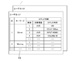
- FIG. 2 shows examples of commands.
- the commands C1 to C4 shown in FIG. 2 are examples of commands for the first device 20-1 (AV receiver), and the commands C5 to C7 are examples of commands for the second device 20-2 (electronic piano).
- the command shown in FIG. 2 uses the HTTP protocol, and a URL is set as the command.
- the command is transmitted to the first device 20-1 or the second device 20-2 in the form of an HTTP request.
- an HTTP daemon is activated, and an HTTP request is accepted by the HTTP daemon, and processing corresponding to the HTTP request is executed.
- an HTTP response indicating the processing result is returned to the command transmission source.
- a command using the HTTP protocol can be transmitted to the third device 20-3 and the fourth device 20-4.
- the command C1 is a command for starting the first device 20-1 from the standby state (non-starting state).
- the “standby state” is a state in which power consumption is reduced compared to the normal state (start-up state). In other words, the standby state is not a state in which the power is completely turned off, and the network communication function and the like are enabled even in the standby state, and command data is received, commands are executed (transmitted), and commands are accepted It is possible to
- the command C2 is a command for switching the input of the first device 20-1 to the external input.
- the first device 20-1 (AV receiver) has a plurality of input terminals (for example, HDMI terminal, external input terminal, etc.), and a plurality of devices 20 including the second device 20-2 are connected to the plurality of input terminals. Is done.
- a speaker (an example of sound emission means) is connected to the first device 20-1, and the first device 20-1 emits a sound signal input from one of the input terminals from the speaker.
- the command C2 is a command for switching the audio signal supplied to the speaker to the audio signal input from the external input terminal.
- Command C3 is a command for setting the output volume.
- the command C4 is a command for requesting device information of the first device 20-1.
- the device information (model name or current status information) of the first device 20-1 is returned to the transmission source of the command C4.
- the command C5 is a command for starting the second device 20-2 from the standby state.
- the command C6 is a command for starting the automatic performance of the second device 20-2 (electronic piano).
- the command C7 is a command for requesting device information of the second device 20-2.
- the command formats of the second device 20-2 and the first device 20-1 may be the same or different.
- the command format may be the same or different between the first device 20-1, the second device 20-2, the third device 20-3, and the fourth device 20-4.
- the voice input device 30 includes a microphone and accepts voice input.
- the voice input device 30 is used for the user to input an operation instruction to the device 20 by voice. For example, when an electronic piano manufactured by Company X is desired to be automatically played, the user inputs “X piano play” or the like to the voice input device 30. In addition, for example, when the user wants to play music on the audio system manufactured by Company X installed in the living room, the user inputs “X play in living room” or the like to the voice input device 30.
- Voice data indicating voice (operation instruction) input to the voice input device 30 is transmitted to the voice recognition device 40 via the Internet 6 together with the user ID.
- the voice recognition device 40 is realized by a server computer, for example.
- the voice recognition device 40 executes voice recognition processing to convert the voice data into data in a format that can be easily understood by the program (command processing system 50). For example, voice data is converted into text data of a predetermined format.
- the operation instruction converted into text data is transmitted to the command processing system 50 together with the user ID.
- the user ID may be given by any Internet-side device (process) until the voice data is transmitted to the command processing system 50.
- a different command processing system 50 is prepared for each manufacturer of the device 20, an operation instruction for the device 20 manufactured by the X company is transmitted to the command processing system 50 for the device 20 manufactured by the X company. . If different command processing systems 50 are prepared for each command format, an operation instruction for the device 20 is transmitted to the command processing system 50 for the command format adopted by the device 20. .
- the command processing system 50 includes a command data transmission device 10, a database 60, and an MQTT (Message Queueing Telemetry Transport) server 70.
- MQTT Message Queueing Telemetry Transport
- the database 60 stores various data.
- the database 60 stores information on the devices 20 owned by each user.
- FIG. 3 shows an example of a device table stored in the database 60.
- the device table T1 is stored for each user (in association with the user ID).
- the user ID used in the command processing system 50 may be different from or the same as the user ID used in the voice input device 30 and the voice recognition device 40. However, when these user IDs are different, correspondence data for converting those user IDs needs to be stored in the command processing system 50 or the voice recognition device 40.
- the device table T1 includes “ID”, “name”, “model”, “MAC address”, “IP address”, “command type”, “terminal”, “volume range”, “connection destination”. ",” Reception availability ", and” Alternative device “fields.
- the “ID” field indicates information for uniquely identifying each device 20 owned by the user.
- the first device 20-1 corresponds to the device ID “1”
- the second device 20-2 corresponds to the device ID “2”.
- “Name” field indicates the name of the device 20. This name is used by the user to specify the device 20 that is the target of the operation instruction. As the name, an arbitrary name set by the user may be used, or a name set by the manufacturer of the device 20 or the like may be used.
- the “model” field indicates the model name (model name) of the device 20.
- the “MAC address” and “IP address” fields indicate the MAC address and IP address set for the wired or wireless network interface card included in the device 20.
- the “command type” field indicates the type (system) of commands used in the device 20. When the command type is determined for each model, a table that associates the model with the command type is provided separately, and instead, the “command type” field is not provided in the device table T1. May be.
- the “terminal” field indicates a list of input terminals provided in the device 20.
- the “volume range” field indicates a volume range that can be set by the device 20. In the “connection destination” field, when the device 20 is connected to the input terminal of the other device 20 and the sound output from the device 20 is input to the other device 20, the other device to which the device 20 is connected is displayed. 20 input terminals are shown.
- the “reception availability” field indicates whether command data can be received via the Internet 6.
- the command data will be described later. For example, “0” or “1” is registered in the “reception availability” field. “0” indicates that command data cannot be received via the Internet 6, and “1” indicates that command data can be received via the Internet 6.
- the “alternative device” field indicates a device 20 (alternative device) that receives command data instead of the device 20 when the device 20 cannot receive command data via the Internet 6.
- the device table T1 is registered by each user.
- the user can register the information of the device 20 owned by the user in the device table T1 by accessing the command data transmitting apparatus 10 from the terminal.
- information on the device 20 may be transmitted to the command processing system 50 (command data transmitting apparatus 10) together with the user ID and registered in the device table T1.
- the database 60 also stores data other than the device table T1. For example, data indicating a correspondence relationship between an operation instruction and a command (in other words, data for converting the operation instruction into a command) is stored in the database 60. This data is stored for each command type (system).
- the command data transmission device 10 is realized by a server computer, for example. As illustrated in FIG. 1, the command data transmission device 10 includes a control unit 11, a storage unit 12, and a communication unit 13. The control unit 11, the storage unit 12, and the communication unit 13 are the same as the control unit 21, the storage unit 22, and the communication unit 23.
- the command data transmitting apparatus 10 may include a component (for example, an optical disk drive or a memory card slot) for reading a program or data stored in an information storage medium (for example, an optical disk or a memory card). And a program may be supplied to the command data transmitter 10 via an information storage medium. The program may be supplied to the command data transmission device 10 via the Internet 6.
- the command data transmission device 10 can access the database 60.
- the command data transmission device 10 and the database 60 may be realized by one server computer or may be realized by another server computer.
- the command data transmission device 10 receives an operation instruction for the device 20, generates command data based on the operation instruction, and transmits the command data to the device 20 or another device 20 (alternative device). As will be described later, the command data is transmitted to the device 20 or another device 20 (alternative device) via the MQTT server 70.
- the MQTT server 70 is for transmitting and receiving data using the MQTT protocol. Command data transmitting apparatus 10 and MQTT server 70 may be realized by one server computer, or may be realized by another server computer.
- FIG. 4 shows an example of functional blocks realized by the command data transmitting apparatus 10 and the device 20.
- the command data transmitting apparatus 10 includes an operation instruction receiving unit 110, a command data generating unit 120, a command data transmitting unit 130, a device information acquiring unit 140, a determining unit 150, a notifying unit 160, and a keyword command registering unit. 170 is included. These functional blocks are realized by the control unit 11, for example.
- the device 20 includes a command data receiving unit 210, a command transmitting unit 220, and a device information transmitting unit 230. These functional blocks are realized by the control unit 21, for example.
- the operation instruction receiving unit 110 receives an operation instruction for the first device 20-1 or the second device 20-2.
- the operation instruction receiving unit 110 receives, from the voice recognition device 40, an operation instruction converted into data in a format that can be easily understood by a program such as text data by the voice recognition device 40.
- the command data generation unit 120 sends a command to be sent to the first device 20-1 or the second device 20-2 to perform an operation according to the operation instruction, and the command is sent to the first device via the LAN 2.
- Command data indicating a destination at the time of transmission to 20-1 or the second device 20-2 is generated.
- Fig. 5 shows an example of command data.
- the command data D1 shown in FIG. 5 is an example of command data generated when an operation instruction for starting the first device 20-1 from the standby state is received. That is, the command data D1 is an example of command data generated when it is desired to execute the command C1 shown in FIG. 2 on the first device 20-1.
- the command data D1 includes items “type”, “id”, and “command”.
- the item “type” indicates the type of data. In the example illustrated in FIG. 5, “cmd” is set to the item “type”. This indicates that the data is command data.
- the item “id” indicates identification information for uniquely identifying data (command data).
- the item “command” indicates the contents of the command data.
- the item “command” includes items “ip”, “path”, and “method”.
- the item “ip” indicates the destination of the command.
- the IP address of the first device 20-1 is set in the item “ip”.
- the item “path” corresponds to the command body.
- the item “ip” corresponds to the IP address portion of the command C1, and the item “path” corresponds to the portion after the IP address of the command C1.
- the item “method” indicates an HTTP protocol method to be used.
- the command data D2 shown in FIG. 5 shows an example of data generated when an operation instruction for starting the second device 20-2 from the standby state is received. That is, the command data D2 is an example of command data generated when it is desired to execute the command C5 shown in FIG. 2 for the second device 20-2. Similar to the command data D1, the command data D2 includes items “type”, “id”, and “command”. In the command data D2, the IP address of the second device 20-2 is set in the item “ip”. In the command data D2, the item “ip” corresponds to the IP address portion of the command C5, and the item “path” corresponds to the portion of the command C5 after the IP address.
- the case where the HTTP protocol GET method is used is shown, but the POST method may be used.
- an item “body” indicating the content transmitted by the POST method is included.
- an item “headers” indicating the content transmitted by the HTTP header information may be included in the command data.
- an item “headers” such as “headers”: [“X-HEADER1: INFO1”, “X-HEADER2: INFO2”] is included in the command data, and the content is added to the HTTP header and transmitted when the command is transmitted. You may do it.
- the command data transmission unit 130 transmits the command data generated by the command data generation unit 120 to the local area device via the Internet 6.
- a “local area device” is a device installed in a local area, a device capable of receiving data via the Internet 6, and a device capable of transmitting commands to a destination via the LAN 2.
- the first device 20-1 can receive data transmitted via the Internet 6 (see FIG. 3). Therefore, when command data indicating a command for the first device 20-1 is generated, the command data transmission unit 130 transmits the command data to the first device 20-1 (local area device) via the Internet 6. .
- the second device 20-2 cannot receive the data transmitted via the Internet 6 (see FIG. 3). Therefore, when command data indicating a command for the second device 20-2 is generated, the command data transmission unit 130 transmits the command data to the first device 20 registered as an alternative device via the Internet 6. -1 (local area device).
- Command data is sent to the local area device using the MQTT protocol. That is, the command data transmission unit 130 transmits command data to the local area device via the MQTT server 70.
- FIG. 6 is a diagram for explaining the MQTT server 70. In FIG. 6, it is assumed that the local area device is the first device 20-1.
- the first topic TP1 is set in the MQTT server 70.
- the first topic TP1 is a topic for transmitting data from the command data transmitting apparatus 10 to the first device 20-1.
- the identification information (name) of the first topic TP1 is set based on the identification information of the first device 20-1. For example, “aabbccdde11_SEND” formed by combining a MAC address that is identification information of the first device 20-1 and a character string “SEND” indicating a topic for transmitting data to the first device 20-1. Is set for the first topic TP1.
- the second topic TP2 is also set in the MQTT server 70.
- the second topic TP2 is a topic for transmitting data (response) from the first device 20-1 to the command data transmitting apparatus 10.
- the identification information (name) of the second topic TP2 is also set based on the identification information of the first device 20-1. For example, “aabbccdde11_RESPOND”, which is a combination of a MAC address that is identification information of the first device 20-1 and a character string “RESPOND” that indicates a topic for transmitting a response to the command data transmitting apparatus 10. Identification information is set for the second topic TP2.
- the command data transmitting unit 130 When transmitting command data to the first device 20-1, the command data transmitting unit 130 publishes the command data to the first topic TP1.
- the first device 20-1 is registered as a subscriber in the first topic TP1, and the command data published to the first topic TP1 is published to the first device 20-1 that subscribes to the first topic TP1. Is done. That is, the command data published to the first topic TP1 is transmitted to the first device 20-1. In this way, the command data is transmitted to the first device 20-1 via the first topic TP1.
- the significance of providing the second topic TP2 will be described later.
- the command data generation unit 120 refers to the device table T1 of the user U1, specifies that the electronic piano is the second device 20-2, and acquires information on the second device 20-2.
- the command data generation unit 120 specifies another device 20 that needs to be operated when the second device 20-2 performs automatic performance.
- the second device 20-2 is connected to the external input terminal of the first device 20-1, and the sound output from the second device 20-2 is emitted from the speaker via the first device 20-1 (
- the command data generation unit 120 identifies the first device 20-1 as the other device 20 that needs to be operated when the second device 20-2 performs automatic performance. Therefore, the command data generation unit 120 generates not only command data indicating a command for the second device 20-2 but also command data indicating a command for the first device 20-1.
- the command data generation unit 120 grasps the type (system) of commands used in the first device 20-1 and the second device 20-2 (see the “command type” or “model” field), and how It is understood whether command data for various types (systems) of commands should be generated. Further, the command data generation unit 120 recognizes that the second device 20-2 cannot receive data via the Internet 6 and that the alternative device of the second device 20-2 is the first device 20-1. (See “Receivability” and “Alternative Device” fields).
- the command data generation unit 120 generates data in which command data indicating a command for the first device 20-1 and command data indicating a command for the second device 20-2 are combined into one, and command data transmission is performed.
- the unit 130 transmits the data to the first device 20-1 via the MQTT server 70.
- array command data data obtained by combining a plurality of command data into one.
- FIG. 7 shows an example of array command data.
- the array command data D4 shown in FIG. 7 includes a plurality of command data.
- “array” is set in the item “type”. This indicates that this data is array command data and includes a plurality of command data.
- an item “array” for storing a plurality of command data is included in the array command data D4.
- the element data D41 is command data for starting the first device 20-1 from the standby state. As described above, since the second device 20-2 is connected to the first device 20-1, the first device 20-1 is put on standby to emit the automatic performance of the second device 20-2 from the speaker. It is necessary to start from the state. For this reason, command data for starting the first device 20-1 is included as element data D41.
- the element data D41 is the same as the command data D1 shown in FIG.
- Element data D42 is waiting time data indicating that a waiting time (delay time) is provided. Since it takes time to activate the first device 20-1, when the next command is executed on the first device 20-1 after the first device 20-1 is activated, the first device 20- It is necessary to wait for the activation of 1 to complete and execute the next command. Therefore, waiting time data is included as element data D42 in order to wait for the activation of the first device 20-1 to be completed.
- “delay” is set in the item “type”. This indicates that the element data D42 is waiting time data.
- the element data D42 includes an item “time”. The item “time” indicates a waiting time. In the example shown in FIG. 7, 500 milliseconds is set in the item “time”.
- a time longer than 500 milliseconds may be set as the waiting time, or a time shorter than 500 milliseconds may be set as the waiting time.
- the waiting time may be set in consideration of the time required for starting up the first device 20-1.
- Element data D43 is command data for switching the input of the first device 20-1 to the external input.
- command data for switching the input of the first device 20-1 to the external input is included as element data D43.
- the IP address portion of the command C2 shown in FIG. 2 is set to the item “ip”, and the portion after the IP address of the command C2 is set to the item “path”.
- Element data D44 is command data for causing the second device 20-2 to start automatic performance.
- the IP address portion of the command C6 shown in FIG. 2 is set to the item “ip”, and the portion after the IP address of the command C6 is set to the item “path”.
- command data for designating music to be automatically played may be transmitted together.
- a predetermined music may be automatically set as an automatic performance target. For example, any one of the tunes registered as favorites or any tune that has been automatically played in the past may be automatically set as an automatic performance target.
- command data for starting up the second device 20-2 from the standby state the second device 20-2, between the element data D43 and the element data D44.
- the waiting time data for waiting for completion of the activation is included as element data.
- the command data transmission unit 130 publishes the array command data D4 to the first topic TP1 of the MQTT server 70. As described above, the array command data D4 published to the first topic TP1 is published to the first device 20-1 subscribed to the first topic TP1. That is, the array command data D4 is transmitted to the first device 20-1.
- the command data receiving unit 210 receives command data via the Internet 6.
- the command transmission unit 220 transmits a command to the destination via the LAN 2 based on the command data.
- the command transmission unit 220 executes the command data included in the array command data D4 in order from the top.
- the command transmission unit 220 executes a command to the first device 20-1 based on the element data D41. That is, based on the items “ip” and “path” of the element data D41, the command transmission unit 220 acquires the command C1 shown in FIG. Then, the command transmission unit 220 accesses the URL set as the command C1. In this case, an HTTP request is transmitted to the first device 20-1. Since the IP address of the first device 20-1 itself is set in the item “ip” of the element data D41, an HTTP request is transmitted to the HTTP daemon of the first device 20-1 itself. As a result, the first device 20-1 is activated from the standby state.
- the command transmission unit 220 waits for a waiting time (500 milliseconds) to elapse.
- a waiting time 500 milliseconds
- the command transmission unit 220 executes a command to the first device 20-1 based on the element data D43. That is, based on the items “ip” and “path” of the element data D43, the command transmission unit 220 acquires the command C2 illustrated in FIG. Then, the command transmission unit 220 accesses the URL set as the command C2. In this case, the input of the first device 20-1 is switched to the external input.
- the command transmission unit 220 acquires the command C5 shown in FIG. 2, and accesses the URL set as the command C5.
- the second device 20-2 is activated from the standby state.
- the command transmission unit 220 waits for the waiting time (for example, 500 milliseconds) to elapse.
- the command transmission unit 220 executes a command to the second device 20-2 based on the element data D44. That is, based on the items “ip” and “path” of the element data D44, the command transmission unit 220 acquires the command C6 illustrated in FIG. Then, the command transmission unit 220 accesses the URL set as the command C6.
- an HTTP request is transmitted to the second device 20-2, and as a result, automatic performance by the second device 20-2 is started.
- the device information acquisition unit 140 acquires device information of the device 20.
- the device information acquisition unit 140 generates command data indicating a command for causing the device 20 to return the device information of the device 20 and a destination when the command is transmitted to the device 20 via the LAN 2.
- the command data is transmitted to the local area device via the Internet 6. Note that the generation and transmission of the command data may also be executed via the command data generation unit 120 and the command data transmission unit 130.
- the device information acquisition unit 140 transmits the command data D5 shown in FIG. 8 to the first device 20-1 via the Internet 6.
- the command data D5 the IP address portion of the command C4 shown in FIG. 2 is set in the item “ip”, and the portion after the IP address in the command C4 is set in the item “path”.
- the device information acquisition unit 140 publishes the command data D5 to the first topic TP1 of the MQTT server 70.
- the command data D5 is transmitted to the first device 20-1.
- the device information transmission unit 230 returns the device information of the device 20 to the command data transmission device 10 via the Internet 6.
- the device information transmission unit 230 acquires the command C4 shown in FIG. 2 based on the command data D5. Then, the device information transmission unit 230 accesses the URL set as the command C4. In this case, an HTTP request is transmitted to the first device 20-1, and device information of the first device 20-1 is returned as an HTTP response.
- the device information in this case includes model information indicating the model of the first device 20-1, current information information indicating the current state of the first device 20-1, and the like.
- the device information transmission unit 230 generates response data indicating the acquired model information, and returns the response data to the command data transmission device 10 via the Internet 6.
- response data D6 shown in FIG. 8 is generated.
- “response” is set in the item “type”. This indicates that this data is response data.
- the same ID as the ID “10” set in the item “id” of the command data D5 is set. This indicates that this data is response data to the command data D5.
- the response data D6 includes an item “response”.
- the item “response” stores device information.
- the item “response” includes items “code” and “model”.
- flag information indicating whether or not the device information has been successfully acquired is set. For example, “0” or “1” is set in the item “code”. “0” indicates that the device information has been successfully acquired, and “1” indicates that the device information has not been normally acquired.
- model model information acquired as part of the device information is set. Although omitted in FIG. 8, an element for storing information other than the model information is also included in the item “response”.
- the device information transmission unit 230 publishes the response data D6 to the second topic TP2 of the MQTT server 70.
- the command data transmitting apparatus 10 is registered as a subscriber in the second topic TP2, and the response data D6 published to the second topic TP2 is published to the first device 20-1 subscribed to the second topic TP2. Is done. That is, the response data D6 published to the second topic TP2 is transmitted to the first device 20-1.
- the device information acquisition unit 140 receives and acquires the response data D6. In this way, the device information acquisition unit 140 acquires device information of the first device 20-1.
- the case where the device information of the first device 20-1 is acquired has been described, but the device information of the second device 20-2, the third device 20-3, or the fourth device 20-4 is acquired in the same manner. it can.
- information other than the model information may be transmitted to the command data transmitting apparatus 10 via the second topic TP2.
- the first device 20-1 executes a normal command (such as a start command)
- the execution result of the command is returned to the first device 20-1 as an HTTP response.
- the result may be returned to the command data transmitting apparatus 10 as a response via the second topic TP2.
- the determination unit 150 determines whether or not the device 20 is in the predetermined first state based on the current state information indicating the current state of the device 20. Then, when the device 20 is in the first state, the command data generation unit 120 generates command data indicating a command for changing the device 20 from the first state to the predetermined second state, and the command data transmission unit 130 May transmit the command data. Specifically, for example, the determination unit 150 determines whether or not the device 20 is in a standby state (an example of a first state) based on the current state information (whether or not the device 20 is in an activated state). To do.
- the command data generation unit 120 When the device 20 is in the standby state (when the device 20 is not in the activated state), the command data generation unit 120 performs a command for starting the device 20 from the standby state (the device 20 is activated from the standby state (second state)). The command data indicating the command to be changed to (example)) may be generated, and the command data transmission unit 130 may transmit the command data.
- the determination unit 150 determines whether or not the first device 20-1 is in an activated state based on the current state information indicating the current state of the first device 20-1. May be. Then, when the first device 20-1 is not in the activated state, the command data generation unit 120 may include command data for activating the first device 20-1 as the element data D41 in the array command data D4. On the other hand, when the first device 20-1 is in the activated state, the command data generating unit 120 may not include the command data for activating the first device 20-1 in the array command data D4. When command data for starting the first device 20-1 is included, wait time data indicating a wait time until the next command is executed (transmitted) may be included after the command data.
- the determination unit 150 may determine whether or not the second device 20-2 is in the activated state based on the current state information indicating the current state of the second device 20-2. Then, when the second device 20-2 is not in the activated state, the command data generation unit 120 may include command data for activating the second device 20-2 in the array command data D4. On the other hand, when the second device 20-2 is in the activated state, the command data generation unit 120 may not include the command data for activating the second device 20-2 in the array command data D4. When command data for starting the second device 20-2 is included, wait time data indicating a wait time until the next command is executed (transmitted) may be included after the command data.
- the determination unit 150 may determine whether or not the instruction sound volume is larger than the reference sound volume.
- the notification unit 160 may notify the user when the instruction volume is larger than the reference volume. That is, the notification unit 160 may notify the user that the instruction sound volume is larger than the reference sound volume, and inquire the user whether there is an error in the instruction sound volume. For example, the notification unit 160 displays or outputs a notification for inquiring the user whether or not there is an error in the designated sound volume via the voice recognition device 40 (or without using the voice recognition device 40). Requests to the voice input device 30. In this case, the user inputs the answer to the question by voice.
- the command data generation unit 120 If there is no error in the designated volume, a voice to that effect is input, and if there is an error in the designated volume, the correct volume is inputted again.
- the answer is supplied to the command data transmission device 10 via the voice recognition device 40. Based on the answer, the command data generation unit 120 generates command data for setting the volume, and the command data transmission unit 130 transmits the command data.
- the instruction volume may be recognized incorrectly. For example, even though the user inputs “18” as the designated sound volume, “80”, whose English pronunciation is similar to “18”, may be recognized as the designated sound volume. In this case, the volume is set much higher than the volume intended by the user. In this regard, by providing the determination unit 150 as described above and setting the reference volume to, for example, “50”, it is possible to prevent the sound from being emitted at a large volume unintended by the user.
- the determination unit 150 may determine whether only one device 20 is installed in the LAN 2 or not. That is, the determination unit 150 may determine whether only one device 20 is registered in the device table T1 with reference to the user device table T1.
- the command data generation unit 120 may consider that the one device 20 is an operation instruction target.
- the notification unit 160 notifies the user that the operation instruction target device 20 has not been specified, and inquires the user of the operation instruction target device 20. Also good. For example, the notification unit 160 notifies the user that the operation instruction target device 20 has not been specified via the voice recognition device 40 (or without the voice recognition device 40), and the operation instruction target The voice input device 30 may be requested to inquire the user about the device 20.
- the keyword command registration unit 170 registers a plurality of command information in the database 60 (an example of a storage unit) in association with one piece of identification information in response to a registration request from the user.
- the user selects a plurality of command information for a specific scene such as a dinner scene from a plurality of command information displayed on the screen of a terminal such as a smartphone or a tablet computer.
- the user has (1) command information for starting the AV receiver from a standby state as a plurality of command information for the dinner scene, and (2) waiting for 500 milliseconds until execution of the next command.
- Standby information (3) command information for switching the input of the AV receiver to the first HDMI terminal (HDMI1), (4) command information for setting the output volume from the AV receiver to “40”, (5) Command information for starting the television receiver from the standby state, (6) Standby information for waiting for 500 milliseconds until execution of the next command, (7) Changing the channel of the television receiver to a specific channel Select command information for Alternatively, the user may use, as a plurality of command information for the dinner scene, (1) command information for starting the AV receiver from the standby state, (2) standby information for waiting for 500 milliseconds until execution of the next command, (3) Command information for switching the input of the AV receiver to external input, (4) Command information for starting the electronic piano from the standby state, (5) Waiting for waiting for 500 milliseconds until execution of the next command Information, (6) command information for setting the performance music of the electronic piano to a specific music (music suitable for a dinner scene), and (7) command information for starting automatic performance of the electronic piano.
- the standby information may be inserted
- the user sets a keyword (identification information) indicating a scene such as “Dinner” for the selected command information.
- a registration request indicating a plurality of selected command information and keywords is transmitted from the terminal to the command data transmitting apparatus 10.
- the keyword command registration unit 170 registers the selected command information in the database 60 in association with the keyword.
- FIG. 9 shows an example of the keyword command table stored in the database 60.
- the keyword command table T2 is stored for each user (in association with the user ID).
- the keyword command table T2 stores a plurality of pieces of command information selected by the user in association with the keywords set by the user.
- information indicating the order, the target device that is the target of the command, and the content of the command is registered as individual command information.
- the command information is information for acquiring command data.
- Information serving as a basis for generating command data may be stored as command information, or the command data itself may be stored as command information.
- the command data generation unit 120 refers to the keyword command table T2 and acquires a plurality of command information associated with the keyword “Dinner”.
- the command data generation unit 120 acquires (generates) command data based on the plurality of command information, and the command data transmission unit 130 transmits the command data to the device 20 via the MQTT server 70.
- the command data generation unit 120 may acquire a plurality of command data
- the command data transmission unit 130 may transmit the plurality of command data one by one
- the command data generation unit 120 may receive the plurality of command data.
- the command data transmission unit 130 may transmit the array command data by generating the array command data combined into one.
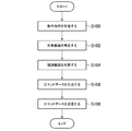
- FIG. 10 shows an example of processing executed when an operation instruction converted into text data is transmitted to the command data transmitting apparatus 10 together with a user ID.
- the control unit 11 executes the processing illustrated in FIG. 10 according to the program, the control unit 11 functions as the operation instruction receiving unit 110, the command data generation unit 120, and the command data transmission unit 130.
- the process shown in FIG. 10 will be described on the assumption that an operation instruction for instructing automatic performance of an electronic piano is received together with a user ID “U1”.
- the control unit 11 receives an operation instruction (S100). Then, the control unit 11 identifies the target device (S102). That is, the control unit 11 refers to the device table T1 of the user U1 and specifies the device 20 that is the target of the operation instruction. For example, since the electronic piano is the second device 20-2, the control unit 11 determines that the second device 20-2 is the target device.
- control unit 11 specifies related devices (S104). That is, the control unit 11 refers to the device table T1 of the user U1 and specifies another device 20 that needs to be operated when the target device performs an operation according to the operation instruction.
- the second device 20-2 is connected to the external input terminal of the first device 20-1, and the sound output from the second device 20-2 is emitted from the speaker via the first device 20-1. Therefore, the control unit 11 identifies the first device 20-1 as a related device.
- control unit 11 generates command data for controlling the target device and related devices (S106).
- the control unit 11 generates command data for causing the first device 20-1 to perform an operation that the first device 20-1 needs to perform when the second device 20-2 performs automatic performance.
- the control unit 11 command data (element data D41) for starting the first device 20-1 from the standby state, or command data for switching the input of the first device 20-1 to an external input. (Element data D43) is generated.
- event data D42 For data that needs to set a waiting time, such as command data for starting the first device 20-1, waiting time data (element data D42) is inserted. At this time, it is determined whether or not the first device 20-1 is in a standby state, and the first device 20-1 is activated from the standby state only when the first device 20-1 is in a standby state.
- Command data (element data D41) and waiting time data (element data D42) may be generated.
- control unit 11 generates command data for causing the second device 20-2 to perform automatic performance. Specifically, the control unit 11 starts command data for starting the second device 20-2 from a standby state, wait time data for setting a wait time, and starts an automatic performance on the second device 20-2. Command data (element data D44) is generated. At this time, it is determined whether or not the second device 20-2 is in the standby state, and the second device 20-2 is activated from the standby state only when the second device 20-2 is in the standby state. Command data and waiting time data may be generated.
- control unit 11 transmits command data (S108).
- control unit 11 refers to the device table T1 of the user U1 and determines whether or not the target device is in a state where data can be received via the Internet 6.
- the control unit 11 transmits command data for the target device to the target device via the MQTT server 70. That is, the control unit 11 publishes command data to a topic for transmission to the target device.
- the control unit 11 refers to the device table T1 of the user U1, identifies an alternative device of the target device, and obtains command data for the target device.
- the data is transmitted to the alternative device via the MQTT server 70. That is, the control unit 11 publishes command data to a topic for transmission to an alternative device.
- the control unit 11 compiles the command data for the target device and the command data for the related device into a single data (array command data) and publishes the above topic. To do. Even if the substitute device is the same as the related device, the control unit 11 individually does not combine the command data for the target device and the command data for the related device into one data (array command data). You may publish to the above topics.
- control unit 11 refers to the device table T1 of the user U1 and determines whether or not the related device is in a state where data can be received via the Internet 6.
- the control unit 11 transmits command data for the related device to the related device via the MQTT server 70. That is, the control unit 11 publishes the command data to a topic for transmission to the related device.
- the control unit 11 refers to the device table T1 of the user U1, specifies an alternative device for the related device, and obtains command data for the related device.
- the data is transmitted to the alternative device via the MQTT server 70. That is, the control unit 11 publishes command data to a topic for transmission to an alternative device.
- the control unit 11 compiles the command data for the target device and the command data for the related device into a single data (array command data) and publishes the topic. To do. Even if the alternative device is the same as the target device, the control unit 11 individually does not combine the command data for the target device and the command data for the related device into one data (array command data). You may publish to the above topics.
- FIG. 11 shows an example of processing executed when command data is transmitted to the device 20.
- the control unit 21 executes the processing shown in FIG. 11 according to the program, the control unit 21 functions as the command data reception unit 210 and the command transmission unit 220.
- the control unit 21 receives command data (S200). Then, the control unit 21 determines whether or not the received command data is array command data (S202). When the received command data is not array command data, that is, when only one command data is received, the control unit 21 acquires a command based on the items “ip” and “path” of the command data ( (S220), the command is transmitted (S222). That is, the control unit 21 accesses the URL acquired as a command. And the control part 21 complete
- the control unit 21 reads the head element data from the array command data (S204). Then, the control unit 21 determines whether or not the element data is command data (S206). When the element data is command data, the control unit 11 acquires a command based on the items “ip” and “path” of the command data (S208), and transmits the command (S210). That is, the control unit 21 accesses the URL generated as a command. Thereafter, the control unit 21 determines whether or not the next element data exists in the array command data (S212). When the next element data exists in the array command data, the control unit 21 reads the element data (S214) and executes step S206.
- the control unit 21 sets the waiting time based on the item “time” of the waiting time data (S216). Then, the control unit 21 monitors whether or not the waiting time has elapsed (S218). When the waiting time has elapsed, the control unit 21 executes Step S212.
- step S212 If it is determined in step S212 that the next element data does not exist in the array command data, the control unit 21 ends this process.
- the element data included in the array command data is either command data or standby time data (that is, “cmd” and “ However, the element data may be data other than command data and standby time data. That is, another process may be executed by setting items other than “cmd” and “time” in the item “type” of the element data.
- command data or array command data is received by the device 20 (that is, either “cmd” or “array” in the data item “type”). However, another process may be executed by setting data item “type” other than “cmd” and “array”.
- FIG. 12 shows an example of processing executed when the device information of the device 20 is acquired.
- the control units 11 and 21 execute the processing illustrated in FIG. 12 according to the program, the control unit 11 functions as the device information acquisition unit 140 and the control unit 21 functions as the device information transmission unit 230.
- the control unit 11 of the command data transmitting apparatus 10 generates command data for acquiring device information of the target device (S110). For example, command data D5 as shown in FIG. 8 is generated. Then, the control unit 11 transmits command data (S112). This process is executed in the same manner as in step S108.
- the control unit 21 of the device 20 acquires a command based on the items “ip” and “path” of the command data (S230), A command is transmitted (S232). That is, the control unit 21 accesses the URL acquired as a command.
- an HTTP request is transmitted to the target device, processing for returning device information is executed in the target device, and device information is returned as an HTTP response.
- the control unit 21 acquires device information (S234), and generates response data based on the device information (S236). For example, response data D6 as shown in FIG. 8 is generated.
- control part 21 transmits response data to the command data transmission apparatus 10 via the MQTT server 70 (S238). That is, the control unit 21 publishes response data to a topic for transmission to the command data transmission device 10. The published response data is transmitted to the command data transmitting apparatus 10.
- the control unit 11 acquires the device information of the target device from the response data (S114). For example, the acquired model information is registered in the database 60 (the device table T1 of the user U1).
- FIG. 13 shows an example of processing executed when a keyword command registration request is transmitted from the user terminal to the command data transmitting apparatus 10.
- the control unit 11 executes the process shown in FIG. 13 according to the program, the control unit 11 functions as the keyword command registration unit 170.
- the control unit 11 receives a keyword command registration request (S120). This registration request is received together with the user ID. This registration request includes keyword information set by the user and a plurality of command information selected by the user.
- the control unit 11 accesses the keyword command table T2 of the user, and registers a plurality of command information selected by the user in the keyword command table T2 in association with the keyword set by the user. (S122).
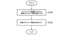
- FIG. 14 shows an example of processing executed when an operation instruction including a keyword is transmitted to the command data transmitting apparatus 10 together with the user ID.
- the control unit 11 refers to the keyword command table T2 of the user, and reads a plurality of command information associated with the keyword (S130). And the control part 11 acquires several command data based on these several command information, and transmits the said several command data (S132). This command data transmission process is executed in the same manner as in step S108.
- the device 20 to which a private IP address is set can be controlled via the Internet 6.
- the user can issue an operation instruction to the device 20 using a service (voice recognition service or the like) provided on the Internet 6.
- the command originally used for controlling the device 20 via the LAN 2 can be diverted when the device 20 is controlled via the Internet 6. As a result, there is no need to define commands separately.
- not all devices 20 need to be able to receive command data from the command data transmitting device 10. If at least one device 20 is in a state in which command data can be received from the command data transmission device 10, a command can be transmitted to another device 20 via the device 20 (alternative device).
- a plurality of command data for one device 20 and a plurality of command data for a plurality of devices 20 can be collectively transmitted as one data (packet) (see FIG. 7).
- a plurality of controls for one device 20 can be transmitted at a time, or a plurality of devices 20 can be controlled simultaneously.
- a plurality of command data can be transmitted / received quickly and the amount of packets can be reduced.
- the device control system 1 it is possible to adjust the time from the execution of a certain command to the execution of the next command by inserting the waiting time data. For example, when a command for starting the device 20 from a standby state is executed, the next command can be executed after the start of the device 20 is completed.
- the MQTT server 70 is provided with two topics, the first topic TP1 and the second topic TP2, and by using them separately, data transmission from the command data transmitting apparatus 10 to the device 20 can be performed. Data transmission from the device 20 to the command data transmission device 10 can be performed. As a result, for example, the command data transmission device 10 can acquire device information of the device 20.
- the first device 20-1, the second device 20-2, the third device 20-3, and the fourth device 20-4 are mainly AV receivers, electronic pianos, and television receivers.
- the device 20 to be controlled by the device control system 1 is not limited to this.
- the device 20 may be an audio device or an audio visual device other than an AV receiver, a television receiver, and a Blu-ray disc player, or an instrument other than an electronic piano (an instrument having a network function such as an electronic organ or a guitar). There may be.
- An audio device, an audiovisual device, or a musical instrument having a network communication function can be controlled by the device control system 1.
- the device 20 may be a device other than an audio device, an audiovisual device, and a musical instrument.
- a device having a network communication function can be a target of control by the device control system 1.
- the local area device that receives the command data from the command data transmission device 10 may be a device other than the device 20 that is the target of control by the device control system 1.
- the local area device may be a network device such as a router, a switch, or a wireless communication access point.
- the voice input device 30 may be connected to the Internet 6 and may not be connected to the same LAN 2 as the device 20.
- the user inputs the operation instruction of the device 20 to the voice input device 30, but the operation instruction may not be input by voice.
- the user may be able to input an operation instruction by selecting a button displayed on the terminal screen.
- the LAN 2 includes both a wired LAN and a wireless LAN, either one may be preferentially used according to the device 20 that is the command transmission destination.
- the command is transmitted via the LAN 2, but the command may be transmitted via a transmission means other than the LAN 2.
- the command may be transmitted via wireless communication other than the wireless LAN such as Bluetooth (registered trademark), or may be transmitted via a cable other than the LAN cable such as an HDMI cable.
- the “local area” is an area where communication is possible via wireless communication or a cable.
- the command is not limited to the format described above (see FIG. 2), and may be in another format.
- the command data is not limited to the format described above (see FIGS. 5, 7, and 8), and may be another format. That is, the command does not have to use the HTTP protocol.
- the command may be a command using Wake On LAN.
- the second device 20-2 is compatible with the Wake On LAN function, a magic packet (corresponding to a command) in which the MAC address of the second device 20-2 is repeated 16 times is sent to the first device 20-
- the second device 20-2 may be activated from the first device 20-1 by transmitting from 1 to the second device 20-2.
- the third device 20-3 or the fourth device 20-4 is activated from the first device 20-1.
- the device table T1 by providing a field indicating whether or not the Wake On LAN function is supported, it is possible to specify whether or not each device 20 supports the Wake On LAN function. do it.
- the third device 20-3 (television receiver) and the fourth device 20-4 (Blu-ray disc player) are connected to the first device 20-1 (AV receiver) via an HDMI cable. Therefore, a command for the third device 20-3 or the fourth device 20-4 may be transmitted via the HDMI cable. Specifically, a command for the third device 20-3 or the fourth device 20-4 may be transmitted using a CEC (Consumer Electronics Control) function defined in the HDMI standard.
- CEC Consumer Electronics Control
- command data for starting up the third device 20-3 is transmitted to the first device 20-1 (an alternative device of the third device 20-3: see FIG. 3).
- a command for starting the third device 20-3 is executed from the device 20-1 to the third device 20-3.
- an ON command (startup command) conforming to the CEC function may be transmitted via the HDMI cable. That is, the command transmission unit 220 of the first device 20-1 may output the command to the first HDMI terminal (HDMI1) to which the third device 20-3 is connected.
- the first device 20-1 to the third device 20-3 are similarly configured in accordance with the CEC function.
- the command may be transmitted via an HDMI cable.
- an operation instruction “X turn off TV” for turning off the television receiver (entering the standby state) is input to the audio input device 30, the first device 20-1 to the third device 20.
- an OFF command conforming to the CEC function may be transmitted via the HDMI cable.
- command data for causing the fourth device 20-4 (Blu-ray disc player) to reproduce the content is transmitted to the first device 20-1 (an alternative device of the fourth device 20-4: see FIG. 3).
- a command for causing the first device 20-1 to reproduce the content is executed from the fourth device 20-4.
- a PLAY command (playback command) conforming to the CEC function may be transmitted via the HDMI cable. That is, the command transmission unit 220 of the first device 20-1 may output the command to the fourth HDMI terminal (HDMI2) to which the fourth device 20-4 is connected.
- the first device 20-1 to the fourth device 20-4 are similarly configured.
- a command (ON, OFF, STOP, SKIP, etc.) conforming to the CEC function may be transmitted via the HDMI cable.
- the device table T1 may be provided with a “control type” field indicating a control type so that each device 20 can be specified via the LAN 2 or the HDMI cable. .
- a “control type” field indicating a control type so that each device 20 can be specified via the LAN 2 or the HDMI cable.
- these devices 20 can execute commands conforming to the CEC function. It is sufficient to be able to specify that it is controlled by.
- a command execution instruction in accordance with the CEC function may be added to a command originally used to control the device 20 via the LAN 2.
- the first device 20-1 when the first device 20-1 performs an operation of outputting an ON command conforming to the CEC function to the first HDMI terminal (HDMI1), “http://192.168.0.2. A command such as “/ ctrl? CEC_ON: HDMI1” may be executed.
- command data including a code transmitted from the remote controller via infrared communication may be generated and transmitted.
- an operation instruction “X watch TV” for viewing a television broadcast on a television receiver manufactured by X company is input to the audio input device 30.
- command data including a code transmitted when starting the third device 20-3 (television receiver) from the remote controller is the first device 20-1 (alternative device of the third device 20-3: FIG. 3) and a command for starting the third device 20-3 is executed from the first device 20-1 to the third device 20-3.
- the first device 20-1 may transmit the code via the LAN 2 or infrared communication.
- the second device 20-2 does not receive the command data (eg, command data D2) indicating the command for the second device 20-2, and the first device 20-1
- the second device 20-2 itself may receive the command data D2.
- two topics for the second device 20-2 are separated from the first topic TP1 and the second topic TP2 that are topics for the first device 20-1.
- the topic of the name based on the address is set in the MQTT server 70, and the second device 20-2 receives command data from the command data transmitting apparatus 10 via one of the topics, Device information or the like may be transmitted to the command data transmitting apparatus 10 via the other of them.
- the third device 20-3 or the fourth device 20-4 receives command data from the command data transmitting apparatus 10 via one of the topics, Device information or the like may be transmitted to the command data transmitting apparatus 10 via the other of them.
- Boot information indicating that the device 20 has been started and connected to the network, shutdown information that the device 20 has been shut down and the network connection has been disconnected, and an error has occurred in the network connection of the device 20 May be transmitted from the device 20 to the command processing system 50 (command data transmitting apparatus 10) via the MQTT server 70.
- the command processing system 50 may manage the state of the device 20 based on the above information.
- command data is transmitted by a method using the MQTT protocol, but other methods may be adopted.
- the command data may be registered in the server, and the command data registered in the server may be downloaded when the device 20 accesses the server.
Abstract
Une unité de réception d'instructionde fonctionnement (110) reçoit une instruction de fonctionnement s'adressant à un dispositif situé dans une zone locale. Une unité de génération de données de commande (120) génère des données de commande qui indiquent : une commande à transmettre au dispositif de façon à amener le dispositif à fonctionner conformément à l'instruction de fonctionnement ; et une destination permettant de transmettre la commande au dispositif par l'intermédiaire d'un moyen de transfert dans la zone locale. Une unité de transmission de données de commande (130) transmet, à un appareil local situé dans la zone locale, les données de commande générées par l'unité de génération de données de commande (120), par l'intermédiaire d'un réseau étendu.
Priority Applications (3)
| Application Number | Priority Date | Filing Date | Title |
|---|---|---|---|
| PCT/JP2016/089215 WO2018123067A1 (fr) | 2016-12-29 | 2016-12-29 | Appareil de transmission de données de commande, appareil local, système de commande de dispositif, procédé de commande d'appareil de transmission de données de commande, procédé de commande d'appareil local, procédé de commande de dispositif et programme |
| JP2018558642A JP6725008B2 (ja) | 2016-12-29 | 2016-12-29 | コマンドデータ送信装置、ローカルエリア装置、機器制御システム、コマンドデータ送信装置の制御方法、ローカルエリア装置の制御方法、機器制御方法、及びプログラム |
| US15/908,379 US10498695B2 (en) | 2016-12-29 | 2018-02-28 | Command data transmission device, local area device, apparatus control system, method for controlling command data transmission device, method for controlling local area device, apparatus control method, and program |
Applications Claiming Priority (1)
| Application Number | Priority Date | Filing Date | Title |
|---|---|---|---|
| PCT/JP2016/089215 WO2018123067A1 (fr) | 2016-12-29 | 2016-12-29 | Appareil de transmission de données de commande, appareil local, système de commande de dispositif, procédé de commande d'appareil de transmission de données de commande, procédé de commande d'appareil local, procédé de commande de dispositif et programme |
Related Child Applications (1)
| Application Number | Title | Priority Date | Filing Date |
|---|---|---|---|
| US15/908,379 Continuation US10498695B2 (en) | 2016-12-29 | 2018-02-28 | Command data transmission device, local area device, apparatus control system, method for controlling command data transmission device, method for controlling local area device, apparatus control method, and program |
Publications (1)
| Publication Number | Publication Date |
|---|---|
| WO2018123067A1 true WO2018123067A1 (fr) | 2018-07-05 |
Family
ID=62708590
Family Applications (1)
| Application Number | Title | Priority Date | Filing Date |
|---|---|---|---|
| PCT/JP2016/089215 WO2018123067A1 (fr) | 2016-12-29 | 2016-12-29 | Appareil de transmission de données de commande, appareil local, système de commande de dispositif, procédé de commande d'appareil de transmission de données de commande, procédé de commande d'appareil local, procédé de commande de dispositif et programme |
Country Status (3)
| Country | Link |
|---|---|
| US (1) | US10498695B2 (fr) |
| JP (1) | JP6725008B2 (fr) |
| WO (1) | WO2018123067A1 (fr) |
Cited By (3)
| Publication number | Priority date | Publication date | Assignee | Title |
|---|---|---|---|---|
| WO2020136892A1 (fr) * | 2018-12-28 | 2020-07-02 | ローランド株式会社 | Dispositif de commande, système d'instrument de musique électronique et procédé de commande |
| JP2020136920A (ja) * | 2019-02-20 | 2020-08-31 | パナソニックIpマネジメント株式会社 | 音声制御システム及び音声制御方法 |
| JP2020167474A (ja) * | 2019-03-28 | 2020-10-08 | パナソニックIpマネジメント株式会社 | 制御システム、制御方法、及び、プログラム |
Families Citing this family (56)
| Publication number | Priority date | Publication date | Assignee | Title |
|---|---|---|---|---|
| US9318108B2 (en) | 2010-01-18 | 2016-04-19 | Apple Inc. | Intelligent automated assistant |
| US8977255B2 (en) | 2007-04-03 | 2015-03-10 | Apple Inc. | Method and system for operating a multi-function portable electronic device using voice-activation |
| US8676904B2 (en) | 2008-10-02 | 2014-03-18 | Apple Inc. | Electronic devices with voice command and contextual data processing capabilities |
| US20120311585A1 (en) | 2011-06-03 | 2012-12-06 | Apple Inc. | Organizing task items that represent tasks to perform |
| US10417037B2 (en) | 2012-05-15 | 2019-09-17 | Apple Inc. | Systems and methods for integrating third party services with a digital assistant |
| US10199051B2 (en) | 2013-02-07 | 2019-02-05 | Apple Inc. | Voice trigger for a digital assistant |
| US10652394B2 (en) | 2013-03-14 | 2020-05-12 | Apple Inc. | System and method for processing voicemail |
| US10748529B1 (en) | 2013-03-15 | 2020-08-18 | Apple Inc. | Voice activated device for use with a voice-based digital assistant |
| US10176167B2 (en) | 2013-06-09 | 2019-01-08 | Apple Inc. | System and method for inferring user intent from speech inputs |
| US10170123B2 (en) | 2014-05-30 | 2019-01-01 | Apple Inc. | Intelligent assistant for home automation |
| EP3480811A1 (fr) | 2014-05-30 | 2019-05-08 | Apple Inc. | Procédé d'entrée à simple énoncé multi-commande |
| US9715875B2 (en) | 2014-05-30 | 2017-07-25 | Apple Inc. | Reducing the need for manual start/end-pointing and trigger phrases |
| US9338493B2 (en) | 2014-06-30 | 2016-05-10 | Apple Inc. | Intelligent automated assistant for TV user interactions |
| US9886953B2 (en) | 2015-03-08 | 2018-02-06 | Apple Inc. | Virtual assistant activation |
| US10200824B2 (en) | 2015-05-27 | 2019-02-05 | Apple Inc. | Systems and methods for proactively identifying and surfacing relevant content on a touch-sensitive device |
| US20160378747A1 (en) | 2015-06-29 | 2016-12-29 | Apple Inc. | Virtual assistant for media playback |
| US10331312B2 (en) | 2015-09-08 | 2019-06-25 | Apple Inc. | Intelligent automated assistant in a media environment |
| US10671428B2 (en) | 2015-09-08 | 2020-06-02 | Apple Inc. | Distributed personal assistant |
| US10740384B2 (en) | 2015-09-08 | 2020-08-11 | Apple Inc. | Intelligent automated assistant for media search and playback |
| US10747498B2 (en) | 2015-09-08 | 2020-08-18 | Apple Inc. | Zero latency digital assistant |
| US10691473B2 (en) | 2015-11-06 | 2020-06-23 | Apple Inc. | Intelligent automated assistant in a messaging environment |
| US10956666B2 (en) | 2015-11-09 | 2021-03-23 | Apple Inc. | Unconventional virtual assistant interactions |
| US10223066B2 (en) | 2015-12-23 | 2019-03-05 | Apple Inc. | Proactive assistance based on dialog communication between devices |
| US10586535B2 (en) | 2016-06-10 | 2020-03-10 | Apple Inc. | Intelligent digital assistant in a multi-tasking environment |
| DK179415B1 (en) | 2016-06-11 | 2018-06-14 | Apple Inc | Intelligent device arbitration and control |
| DK201670540A1 (en) | 2016-06-11 | 2018-01-08 | Apple Inc | Application integration with a digital assistant |
| US10726832B2 (en) | 2017-05-11 | 2020-07-28 | Apple Inc. | Maintaining privacy of personal information |
| DK180048B1 (en) | 2017-05-11 | 2020-02-04 | Apple Inc. | MAINTAINING THE DATA PROTECTION OF PERSONAL INFORMATION |
| DK201770428A1 (en) | 2017-05-12 | 2019-02-18 | Apple Inc. | LOW-LATENCY INTELLIGENT AUTOMATED ASSISTANT |
| DK179745B1 (en) | 2017-05-12 | 2019-05-01 | Apple Inc. | SYNCHRONIZATION AND TASK DELEGATION OF A DIGITAL ASSISTANT |
| DK179496B1 (en) | 2017-05-12 | 2019-01-15 | Apple Inc. | USER-SPECIFIC Acoustic Models |
| US20180336892A1 (en) | 2017-05-16 | 2018-11-22 | Apple Inc. | Detecting a trigger of a digital assistant |
| US20180336275A1 (en) | 2017-05-16 | 2018-11-22 | Apple Inc. | Intelligent automated assistant for media exploration |
| JP6962158B2 (ja) | 2017-12-01 | 2021-11-05 | ヤマハ株式会社 | 機器制御システム、機器制御方法、及びプログラム |
| JP7192208B2 (ja) * | 2017-12-01 | 2022-12-20 | ヤマハ株式会社 | 機器制御システム、デバイス、プログラム、及び機器制御方法 |
| JP7067082B2 (ja) | 2018-01-24 | 2022-05-16 | ヤマハ株式会社 | 機器制御システム、機器制御方法、及びプログラム |
| JP6928842B2 (ja) * | 2018-02-14 | 2021-09-01 | パナソニックIpマネジメント株式会社 | 制御情報取得システム、及び、制御情報取得方法 |
| US10818288B2 (en) | 2018-03-26 | 2020-10-27 | Apple Inc. | Natural assistant interaction |
| US11145294B2 (en) | 2018-05-07 | 2021-10-12 | Apple Inc. | Intelligent automated assistant for delivering content from user experiences |
| US10928918B2 (en) | 2018-05-07 | 2021-02-23 | Apple Inc. | Raise to speak |
| DK180639B1 (en) | 2018-06-01 | 2021-11-04 | Apple Inc | DISABILITY OF ATTENTION-ATTENTIVE VIRTUAL ASSISTANT |
| DK179822B1 (da) | 2018-06-01 | 2019-07-12 | Apple Inc. | Voice interaction at a primary device to access call functionality of a companion device |
| US10892996B2 (en) | 2018-06-01 | 2021-01-12 | Apple Inc. | Variable latency device coordination |
| US11462215B2 (en) | 2018-09-28 | 2022-10-04 | Apple Inc. | Multi-modal inputs for voice commands |
| US11348573B2 (en) | 2019-03-18 | 2022-05-31 | Apple Inc. | Multimodality in digital assistant systems |
| DK201970509A1 (en) | 2019-05-06 | 2021-01-15 | Apple Inc | Spoken notifications |
| US11307752B2 (en) | 2019-05-06 | 2022-04-19 | Apple Inc. | User configurable task triggers |
| US11140099B2 (en) | 2019-05-21 | 2021-10-05 | Apple Inc. | Providing message response suggestions |
| DK201970510A1 (en) | 2019-05-31 | 2021-02-11 | Apple Inc | Voice identification in digital assistant systems |
| DK180129B1 (en) | 2019-05-31 | 2020-06-02 | Apple Inc. | USER ACTIVITY SHORTCUT SUGGESTIONS |
| US11468890B2 (en) | 2019-06-01 | 2022-10-11 | Apple Inc. | Methods and user interfaces for voice-based control of electronic devices |
| US11061543B1 (en) | 2020-05-11 | 2021-07-13 | Apple Inc. | Providing relevant data items based on context |
| US11043220B1 (en) | 2020-05-11 | 2021-06-22 | Apple Inc. | Digital assistant hardware abstraction |
| US11755276B2 (en) | 2020-05-12 | 2023-09-12 | Apple Inc. | Reducing description length based on confidence |
| US11490204B2 (en) | 2020-07-20 | 2022-11-01 | Apple Inc. | Multi-device audio adjustment coordination |
| US11438683B2 (en) | 2020-07-21 | 2022-09-06 | Apple Inc. | User identification using headphones |
Citations (4)
| Publication number | Priority date | Publication date | Assignee | Title |
|---|---|---|---|---|
| JP2001128262A (ja) * | 1999-10-28 | 2001-05-11 | Yokogawa Electric Corp | リモートコントロールシステム |
| JP2004015627A (ja) * | 2002-06-10 | 2004-01-15 | Sharp Corp | Av機器の遠隔制御システム |
| JP2005109763A (ja) * | 2003-09-29 | 2005-04-21 | Nec Corp | ネットワークシステム,wol装置,ネットワークtvチューナ,及び情報装置起動方法 |
| JP2015106358A (ja) * | 2013-12-02 | 2015-06-08 | 日立アプライアンス株式会社 | リモートアクセスシステムおよび宅内機器制御装置 |
Family Cites Families (3)
| Publication number | Priority date | Publication date | Assignee | Title |
|---|---|---|---|---|
| KR20120032644A (ko) * | 2010-09-29 | 2012-04-06 | 주식회사 팬택 | 이동 단말기 및 이동 단말기를 이용한 제어 방법 |
| JP6213181B2 (ja) | 2013-11-20 | 2017-10-18 | ヤマハ株式会社 | 同期再生システム及び同期再生方法 |
| US10038941B2 (en) * | 2015-12-07 | 2018-07-31 | Caavo Inc | Network-based control of a media device |
-
2016
- 2016-12-29 JP JP2018558642A patent/JP6725008B2/ja active Active
- 2016-12-29 WO PCT/JP2016/089215 patent/WO2018123067A1/fr active Application Filing
-
2018
- 2018-02-28 US US15/908,379 patent/US10498695B2/en active Active
Patent Citations (4)
| Publication number | Priority date | Publication date | Assignee | Title |
|---|---|---|---|---|
| JP2001128262A (ja) * | 1999-10-28 | 2001-05-11 | Yokogawa Electric Corp | リモートコントロールシステム |
| JP2004015627A (ja) * | 2002-06-10 | 2004-01-15 | Sharp Corp | Av機器の遠隔制御システム |
| JP2005109763A (ja) * | 2003-09-29 | 2005-04-21 | Nec Corp | ネットワークシステム,wol装置,ネットワークtvチューナ,及び情報装置起動方法 |
| JP2015106358A (ja) * | 2013-12-02 | 2015-06-08 | 日立アプライアンス株式会社 | リモートアクセスシステムおよび宅内機器制御装置 |
Cited By (4)
| Publication number | Priority date | Publication date | Assignee | Title |
|---|---|---|---|---|
| WO2020136892A1 (fr) * | 2018-12-28 | 2020-07-02 | ローランド株式会社 | Dispositif de commande, système d'instrument de musique électronique et procédé de commande |
| JP2020136920A (ja) * | 2019-02-20 | 2020-08-31 | パナソニックIpマネジメント株式会社 | 音声制御システム及び音声制御方法 |
| JP2020167474A (ja) * | 2019-03-28 | 2020-10-08 | パナソニックIpマネジメント株式会社 | 制御システム、制御方法、及び、プログラム |
| JP7038294B2 (ja) | 2019-03-28 | 2022-03-18 | パナソニックIpマネジメント株式会社 | 制御システム、制御方法、及び、プログラム |
Also Published As
| Publication number | Publication date |
|---|---|
| US10498695B2 (en) | 2019-12-03 |
| JP6725008B2 (ja) | 2020-07-15 |
| US20180191670A1 (en) | 2018-07-05 |
| JPWO2018123067A1 (ja) | 2019-06-27 |
Similar Documents
| Publication | Publication Date | Title |
|---|---|---|
| JP6725008B2 (ja) | コマンドデータ送信装置、ローカルエリア装置、機器制御システム、コマンドデータ送信装置の制御方法、ローカルエリア装置の制御方法、機器制御方法、及びプログラム | |
| KR101143691B1 (ko) | 정보 제어 방법, 정보 재생 시스템, 정보 제공 장치, 정보 재생 장치, 및 기록 매체 | |
| US8613028B2 (en) | Audiovisual multi-room support | |
| US10326662B2 (en) | System and method for managing playback of streaming digital content | |
| US8856273B2 (en) | Information processing device and information processing method for communication with an external device via a network | |
| US8619803B2 (en) | Sparse mode system | |
| US10938595B2 (en) | Device control system, device control method, and non-transitory computer readable storage medium | |
| US8928553B2 (en) | Method and apparatus for accessing device based on intuitive selection | |
| US7456905B2 (en) | Communication apparatus and method, recording medium, and program | |
| JP2009200788A (ja) | 受信装置 | |
| US9363550B2 (en) | Information processing apparatus, television receiver, information processing method, program, and information processing system | |
| JP2006309385A (ja) | 電子機器システムおよびプログラム | |
| US11050579B2 (en) | Distribution destination specifying device and distribution destination specifying method | |
| US20130079909A1 (en) | Audio outputting apparatus and program of the same | |
| EP3780641B1 (fr) | Dispositif de traitement d'informations, procédé de traitement d'informations dispositif de transmission et procédé de transmission | |
| US8380813B2 (en) | Network terminal apparatus and method of requesting distribution | |
| JP2019101254A (ja) | コマンドデータ生成システム及びコマンド生成方法 | |
| KR20220053795A (ko) | 인공지능 비서 서비스 제공 시스템 및 방법 | |
| JP2010067182A (ja) | サーバー及びクライアント装置 | |
| US20070061850A1 (en) | Electronic device tuning system | |
| JP2018056727A (ja) | 映像音声出力装置 | |
| JP2015039082A (ja) | コンテンツ配信装置及びコンテンツ配信方法 | |
| JP2006323461A (ja) | 電子機器システムおよびプログラム |
Legal Events
| Date | Code | Title | Description |
|---|---|---|---|
| 121 | Ep: the epo has been informed by wipo that ep was designated in this application |
Ref document number: 16925670 Country of ref document: EP Kind code of ref document: A1 |
|
| ENP | Entry into the national phase |
Ref document number: 2018558642 Country of ref document: JP Kind code of ref document: A |
|
| NENP | Non-entry into the national phase |
Ref country code: DE |
|
| 122 | Ep: pct application non-entry in european phase |
Ref document number: 16925670 Country of ref document: EP Kind code of ref document: A1 |