WO2018123049A1 - 誘導加熱装置の診断装置 - Google Patents
誘導加熱装置の診断装置 Download PDFInfo
- Publication number
- WO2018123049A1 WO2018123049A1 PCT/JP2016/089180 JP2016089180W WO2018123049A1 WO 2018123049 A1 WO2018123049 A1 WO 2018123049A1 JP 2016089180 W JP2016089180 W JP 2016089180W WO 2018123049 A1 WO2018123049 A1 WO 2018123049A1
- Authority
- WO
- WIPO (PCT)
- Prior art keywords
- induction heating
- heating device
- diagnostic
- abnormality
- locations
- Prior art date
- Legal status (The legal status is an assumption and is not a legal conclusion. Google has not performed a legal analysis and makes no representation as to the accuracy of the status listed.)
- Ceased
Links
Images



Classifications
-
- G—PHYSICS
- G05—CONTROLLING; REGULATING
- G05B—CONTROL OR REGULATING SYSTEMS IN GENERAL; FUNCTIONAL ELEMENTS OF SUCH SYSTEMS; MONITORING OR TESTING ARRANGEMENTS FOR SUCH SYSTEMS OR ELEMENTS
- G05B23/00—Testing or monitoring of control systems or parts thereof
- G05B23/02—Electric testing or monitoring
-
- H—ELECTRICITY
- H05—ELECTRIC TECHNIQUES NOT OTHERWISE PROVIDED FOR
- H05B—ELECTRIC HEATING; ELECTRIC LIGHT SOURCES NOT OTHERWISE PROVIDED FOR; CIRCUIT ARRANGEMENTS FOR ELECTRIC LIGHT SOURCES, IN GENERAL
- H05B6/00—Heating by electric, magnetic or electromagnetic fields
- H05B6/02—Induction heating
- H05B6/10—Induction heating apparatus, other than furnaces, for specific applications
Definitions
- This invention relates to a diagnostic device for an induction heating device.
- Patent Document 1 discloses an optical fiber sensor. According to the optical fiber sensor, it is possible to detect temperatures at a plurality of locations of the induction heating device.
- Patent Document 1 does not specifically propose a method for diagnosing abnormality of the induction heating device based on the detected temperature. For this reason, the abnormality of the induction heating apparatus cannot be accurately diagnosed.
- An object of the present invention is to provide a diagnostic device for an induction heating device that can accurately diagnose abnormality of the induction heating device.
- the diagnostic apparatus for an induction heating device is based on a comparison of temperature detection values at a plurality of locations of the induction heating device and a temporal change in temperature detection values at each location of the induction heating device.
- the analysis part which analyzes the detected value of the temperature of several places of this, and the diagnostic part which diagnoses abnormality for every location of the said induction heating apparatus based on the analysis result of the detected value by the said analysis part.
- the diagnosis unit is configured for each location of the induction heating device based on the comparison of the temperature detection values at a plurality of locations of the induction heating device and the temporal change in the temperature detection value for each location of the induction heating device. Diagnose the abnormality. For this reason, abnormality of the induction heating apparatus can be diagnosed with high accuracy.
- FIG. 1 is a configuration diagram of a hot rolling line for steel to which a diagnostic apparatus for an induction heating apparatus according to Embodiment 1 of the present invention is applied.
- the heating furnace 1 is provided in the uppermost stream of the hot rolling line for steel.
- the rough rolling mill 2 is provided on the downstream side of the heating furnace 1.
- the finish rolling mill 3 is provided on the downstream side of the rough rolling mill 2.
- the induction heating device 4 is provided between the roughing mill 2 and the finishing mill 3.
- the rolled material 5 is extracted from the heating furnace 1.
- the rolled material 5 is rolled into a rough rolling mill 2 and a finish rolling mill 3.
- the rolled material 5 becomes a thin plate having a desired thickness and width.
- the induction heating device 4 is an edge heater.
- the induction heating device 4 increases the temperature of both sides of the rolled material 5 when the temperature of both sides of the rolled material 5 being conveyed in the hot rolling line for steel is lowered. As a result, the load on the finishing mill 3 is reduced. Moreover, the material of the rolling material 5 is controlled appropriately. As a result, a high-grade steel sheet is manufactured.
- the induction heating device 4 includes an inductor.
- the inductor is provided inside the induction heating device 4.
- the heating coil is wound.
- the inductor induces heating.
- a heat-resistant insulator (not shown) covers the heating coil. As a result, the heating coil is protected from radiant heat from the rolled material 5, scale, water, water vapor, and the like.
- a shield cover or a heat resistant plate (not shown) covers the heat resistant insulator. As a result, radiant heat, scale, water, water vapor and the like from the rolled material 5 do not enter the induction heating device 4.
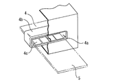
- FIG. 2 is a perspective view of a main part of the induction heating apparatus to which the diagnostic apparatus for the induction heating apparatus according to Embodiment 1 of the present invention is applied.
- the induction heating device 4 has a robust structure.
- the induction heating device 4 is manufactured by combining members whose size and weight are limited to improve maintainability.
- the induction heating device 4 is an induction heating device described in Japanese Patent Laid-Open No. 2012-163459.
- the induction heating device 4 includes a heat-resistant plate 4a, a heating coil 4b, and an optical fiber sensor 4c.
- the heat resistant plate 4 a faces the rolled material 5.
- the heating coil 4b is covered with a heat resistant plate 4a.
- the optical fiber sensor 4c is disposed between the heat resistant plate 4a and the heating coil 4b.
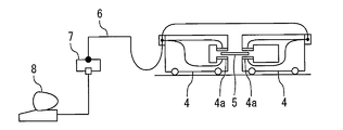
- FIG. 3 is a configuration diagram of a system including a diagnostic device for an induction heating device according to Embodiment 1 of the present invention.
- the optical fiber 6 is connected to the optical fiber sensor 4c.
- the data conversion device 7 is connected to the optical fiber 6.
- the diagnostic device 8 is connected to the data conversion device 7.
- the display device 9 is connected to the diagnostic device 8.
- the data converter 7 always receives the Raman scattered light from the optical fiber sensor 4 c through the optical fiber 6.
- the data converter 7 converts the Raman scattered light data into temperature data.
- the diagnostic device 8 stores the temperature data from the data conversion device 7.
- the diagnostic device 8 recognizes temperatures at a plurality of locations of the induction heating device 4 based on the temperature data.
- the diagnostic device 8 diagnoses normality or abnormality for each location of the induction heating device 4 based on the temperature.
- the diagnostic device 8 causes the display device 9 to display a diagnostic result for each location of the induction heating device 4.
- FIG. 4 is a block diagram of the diagnostic apparatus for the induction heating apparatus according to Embodiment 1 of the present invention.
- the diagnosis device 8 includes a storage unit 8a, an analysis unit 8b, a diagnosis unit 8c, and a display control unit 8d.
- the storage unit 8a stores all of the enormous detection value data collected in the past.
- the storage unit 8 a stores temperature detection value data for each location of the induction heating device 4 in association with the operation status information of the induction heating device 4 and the time information.
- the analyzing unit 8b analyzes the temperature detection values at a plurality of locations of the induction heating device 4. At this time, the analysis unit 8b performs analysis using the feature value of the detected value.
- the feature amount is defined by an average value, a median value, a maximum value, a minimum value, a standard deviation, a variance, and the like of detected values.
- the feature amount is defined by frequency, amplitude, and the like.
- the analysis unit 8b compares the feature amounts of the detected values of the temperatures at a plurality of locations of the induction heating device 4. Specifically, when there are X temperature detection points, 2 points to X points are selected. At this time, the analysis unit 8b compares the feature amount of the detected temperature value at the selected location. The analysis unit 8 b compares temporal changes in the feature value of the detection value for each location of the induction heating device 4. The analysis unit 8 b analyzes feature quantities of detected values of temperatures at a plurality of locations of the induction heating device 4. The analysis unit 8 b analyzes the temporal change in the feature value of the detection value for each location of the induction heating device 4. The analysis unit 8b diagnoses the normality or abnormality of the temperature at a plurality of locations based on these analysis results.
- the analysis unit 8b analyzes the detected values of temperatures at a plurality of locations of the induction heating device 4 according to the operation status of the induction heating device 4. For example, the analysis unit 8b detects the temperatures at a plurality of locations of the induction heating device 4 by grouping the detection values according to the specified range when the range of the detection value of the temperature to be analyzed and the period are specified. Parse the value. For example, the analysis unit 8b analyzes the temperature detection values at a plurality of locations of the induction heating device 4 using a plurality of methods.
- the diagnosis unit 8c diagnoses an abnormality for each location of the induction heating device 4 based on the analysis result of the detection value by the analysis unit 8b. For example, the diagnosis unit 8c diagnoses the possibility of abnormality based on the analysis of the detected value by each of a plurality of methods. The diagnosis unit 8c diagnoses an abnormality for each location of the induction heating device 4 based on a diagnosis result of the possibility of abnormality by each of a plurality of methods. For example, the diagnosis unit 8c diagnoses a part diagnosed as having an abnormality possibility by more than half of a plurality of methods as an abnormality.
- the diagnosis unit 8c compares the feature values of the detected values from time Xn to Xn + 1 and the feature values of the detected values from time Xn-1 to Xn in time series, and immediately normal Capture changes from various detected values. At this time, it is determined that the feature value of the detected value from the time X n ⁇ 1 to X n is normal compared with the feature value of the detected value from the current X n ⁇ 2 to X n ⁇ 1 .
- the diagnosis unit 8c takes into account that the accuracy of the output solution is affected by the change of the collinearity depending on the analysis environment mainly based on the operation status. For example, the diagnosis unit 8c outputs the change in the variance expansion coefficient of the feature value of the detected value in the regression problem simultaneously with the regression problem.
- the diagnosis unit 8c diagnoses an abnormality based on the result of handling and comparing the feature values of the detected values obtained by matrix factorization or the like at the timing when the detected values restricted by the specified conditions are collected.
- the display control unit 8d causes the display device 9 to display a diagnosis result for each location of the induction heating device 4 by the diagnosis unit 8c.
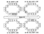
- FIG. 5 is a diagram for explaining a display example by the diagnostic device for the induction heating device in Embodiment 1 of the present invention.
- the display of the diagnosis result is displayed in a clarified state for each temperature detection location by the optical fiber sensor 4c.
- the number of times diagnosed as abnormal is displayed for each temperature detection location by the optical fiber sensor 4c.
- the location diagnosed as abnormal is displayed in a different color from the other locations.
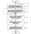
- FIG. 6 is a flowchart for explaining an operation example of the diagnostic apparatus for the induction heating device according to Embodiment 1 of the present invention.
- step S1 the analysis unit 8b compares feature values of detected values of temperatures at a plurality of locations of the induction heating device.
- step S ⁇ b> 2 the analysis unit 8 b calculates a temporal change in the feature amount of the detected temperature value for each location of the induction heating device.
- step S3 the analysis unit 8b performs induction heating based on the comparison of the feature values of the temperature detection values at a plurality of locations of the induction heating device and the temporal change in the feature value of the temperature detection value at each location of the induction heating device. Analyze temperature detection values at multiple locations on the device. Thereafter, the process proceeds to step S4.
- step S4 the diagnosis unit 8c diagnoses an abnormality for each location of the induction heating device based on the analysis result of the detection value by the analysis unit 8b. Thereafter, the process proceeds to step S5.
- step S5 the display control unit 8d causes the display device 9 to display a diagnosis result for each location of the induction heating device by the diagnosis unit 8c. Thereafter, the operation ends.
- the diagnosis unit 8c compares the detected temperature values at a plurality of locations of the induction heating device 4 and the temporal change of the detected temperature values at each location of the induction heating device 4. Based on the above, abnormality is diagnosed for each location of the induction heating device 4. For this reason, abnormality of the induction heating apparatus 4 can be diagnosed with high accuracy.
- the malfunction of the induction heating device 4 can be detected in advance. For this reason, the maintenance plan of the induction heating apparatus 4 can be appropriately drawn up. As a result, it is possible to perform a long-term stop of the hot rolling line for steel and a maintenance inspection requiring a lot of costs at an appropriate timing.
- the abnormality diagnosis is performed according to the operation status of the induction heating device 4. For this reason, even when the standard is completely different due to the presence or absence of radiant heat from the rolled material 5 and the induction heating of the induction heating device 4 such as when the induction heating device 4 is in operation and when it is stopped, erroneous diagnosis of abnormality is prevented. be able to. For example, even when fluctuations in the feature value of the detection value being stopped when the feature value is extracted using all of the acquired detection values as the analysis target, a few seconds until the next rolling material 5 is charged It is possible to prevent misdiagnosis of abnormalities during the stop period.
- abnormality diagnosis is performed according to the specified range when the range of the detected temperature value and the period to be analyzed is specified. For this reason, the data amount of the detected value used for analysis can be reduced. As a result, the calculation time can be shortened. In this case, the load on the diagnostic device 8 can be reduced.
- the abnormality diagnosis is performed based on the diagnosis result of the possibility of abnormality by each of a plurality of methods. For this reason, the accuracy of abnormality diagnosis can be improved.
- the abnormality diagnosis result is displayed on the display device 9. For this reason, it is possible to more accurately notify the manager of the diagnostic device 8 of the abnormal condition of the induction heating device 4.
- FIG. FIG. 7 is a perspective view of a main part of the induction heating apparatus to which the diagnostic apparatus for the induction heating apparatus in Embodiment 2 of the present invention is applied.
- symbol is attached
- the induction heating device 4 of Embodiment 1 is an edge heater.
- the induction heating device 4 of Embodiment 2 is a bar heater.
- the induction heating device 4 of the second embodiment makes the temperature of the rolled material 5 being conveyed in the hot rolling line for steel uniform.
- the plurality of optical fiber sensors 4c are formed in a sheet shape.
- the plurality of optical fiber sensors 4c are the optical fiber sensors 4c described in Japanese Patent Application Laid-Open No. 2012-163459.
- the plurality of optical fiber sensors 4 c are provided below the induction heating device 4.
- FIG. 8 is a diagram for explaining a display example by the diagnostic device for the induction heating device in the second embodiment of the present invention.
- the display of the diagnosis result is displayed in a clarified state for each temperature detection location by the optical fiber sensor 4c.
- the number of times diagnosed as abnormal is displayed for each temperature detection location by the optical fiber sensor 4c.
- the location diagnosed as abnormal is displayed in a different color from the other locations.
- the manager of the diagnostic device 8 can be notified of the abnormal condition of the induction heating device 4 more accurately.
- optical fiber sensors 4c may be arranged so as to face both side portions of the rolled material 5. In this case, it is possible to diagnose both sides of the rolled material 5 where the temperature abnormality progresses quickly with fewer optical fiber sensors 4c.
- the induction heating apparatus diagnosis apparatus can be used in a system for accurately diagnosing an abnormality in the induction heating apparatus.
Landscapes
- Physics & Mathematics (AREA)
- Electromagnetism (AREA)
- General Physics & Mathematics (AREA)
- Engineering & Computer Science (AREA)
- Automation & Control Theory (AREA)
- General Induction Heating (AREA)
Abstract
誘導加熱装置の異常を精度よく診断することができる誘導加熱装置の診断装置を提供する。誘導加熱装置の診断装置は、誘導加熱装置の複数箇所の温度の検出値の比較と前記誘導加熱装置の箇所毎の温度の検出値の時間的変化とに基づいて前記誘導加熱装置の複数箇所の温度の検出値を解析する解析部と、前記解析部による検出値の解析結果に基づいて前記誘導加熱装置の箇所毎に異常を診断する診断部と、を備えた。
Description
この発明は、誘導加熱装置の診断装置に関する。
特許文献1は、光ファイバセンサを開示する。当該光ファイバセンサによれば、誘導加熱装置の複数箇所の温度を検出することができる。
しかしながら、特許文献1においては、検出された温度に基づいた誘導加熱装置の異常の診断方法が具体的に提案されていない。このため、誘導加熱装置の異常を精度よく診断することができない。
この発明は、上述の課題を解決するためになされた。この発明の目的は、誘導加熱装置の異常を精度よく診断することができる誘導加熱装置の診断装置を提供することである。
この発明に係る誘導加熱装置の診断装置は、誘導加熱装置の複数箇所の温度の検出値の比較と前記誘導加熱装置の箇所毎の温度の検出値の時間的変化とに基づいて前記誘導加熱装置の複数箇所の温度の検出値を解析する解析部と、前記解析部による検出値の解析結果に基づいて前記誘導加熱装置の箇所毎に異常を診断する診断部と、を備えた。
この発明によれば、診断部は、誘導加熱装置の複数箇所の温度の検出値の比較と誘導加熱装置の箇所毎の温度の検出値の時間的変化とに基づいて誘導加熱装置の箇所毎に異常を診断する。このため、誘導加熱装置の異常を精度よく診断することができる。
この発明を実施するための形態について添付の図面に従って説明する。なお、各図中、同一又は相当する部分には同一の符号が付される。当該部分の重複説明は適宜に簡略化ないし省略する。
実施の形態1.
図1はこの発明の実施の形態1における誘導加熱装置の診断装置が適用される鉄鋼用熱間圧延ラインの構成図である。
図1はこの発明の実施の形態1における誘導加熱装置の診断装置が適用される鉄鋼用熱間圧延ラインの構成図である。
図1において、加熱炉1は、鉄鋼用熱間圧延ラインの最上流に設けられる。粗圧延機2は、加熱炉1の下流側に設けられる。仕上圧延機3は、粗圧延機2の下流側に設けられる。誘導加熱装置4は、粗圧延機2と仕上圧延機3との間に設けられる。
圧延材5は、加熱炉1から抽出される。圧延材5は、粗圧延機2と仕上圧延機3とに圧延される。その結果、圧延材5は、所望の厚さと幅とを備えた薄板となる。
例えば、誘導加熱装置4は、エッジヒータである。誘導加熱装置4は、鉄鋼用熱間圧延ラインの搬送中の圧延材5の両側部の温度が下がった際に圧延材5の両側部の温度を上げる。その結果、仕上圧延機3の負荷が軽減される。また、圧延材5の材質が適切に制御される。その結果、高級な鋼板が製造される。
誘導加熱装置4は、インダクタを備える。インダクタは、誘導加熱装置4の内部に設けられる。インダクタにおいて、加熱コイルは、巻き回される。インダクタは、加熱を誘導する。
図示しない耐熱性絶縁体は、加熱コイルを覆う。その結果、加熱コイルは、圧延材5からの輻射熱、スケール、水、水蒸気等から保護される。図示しないシールドカバーまたは耐熱プレートは、耐熱性絶縁体を覆う。その結果、圧延材5からの輻射熱、スケール、水、水蒸気等は、誘導加熱装置4の内部に侵入しない。
次に、図2を用いて、誘導加熱装置4の要部を説明する。
図2はこの発明の実施の形態1における誘導加熱装置の診断装置が適用される誘導加熱装置の要部の斜視図である。
図2はこの発明の実施の形態1における誘導加熱装置の診断装置が適用される誘導加熱装置の要部の斜視図である。
誘導加熱装置4は、堅牢な構造を備える。誘導加熱装置4は、保守性向上のために大きさと重量が制限された部材を組み合わせて製作される。例えば、誘導加熱装置4は、日本特開2012-163459号公報に記載された誘導加熱装置である。誘導加熱装置4は、耐熱プレート4aと加熱コイル4bと光ファイバセンサ4cとを備える。
耐熱プレート4aは、圧延材5と対向する。加熱コイル4bは、耐熱プレート4aに覆われる。光ファイバセンサ4cは、耐熱プレート4aと加熱コイル4bとの間に配置される。
次に、図3を用いて、誘導加熱装置4の異常の診断方法を説明する。
図3はこの発明の実施の形態1における誘導加熱装置の診断装置を含むシステムの構成図である。
図3はこの発明の実施の形態1における誘導加熱装置の診断装置を含むシステムの構成図である。
図3において、光ファイバ6は、光ファイバセンサ4cに接続される。データ変換装置7は、光ファイバ6に接続される。診断装置8は、データ変換装置7に接続される。表示装置9は、診断装置8に接続される。
データ変換装置7は、光ファイバ6を通して光ファイバセンサ4cからのラマン散乱光を常に受ける。データ変換装置7は、当該ラマン散乱光のデータを温度のデータに変換する。診断装置8は、データ変換装置7からの温度のデータを記憶する。診断装置8は、当該温度のデータに基づいて誘導加熱装置4の複数箇所の温度を認識する。診断装置8は、当該温度に基づいて誘導加熱装置4の箇所毎に正常または異常を診断する。診断装置8は、誘導加熱装置4の箇所毎の診断結果を表示装置9に表示させる。
次に、図4を用いて、診断装置8を説明する。
図4はこの発明の実施の形態1における誘導加熱装置の診断装置のブロック図である。
図4はこの発明の実施の形態1における誘導加熱装置の診断装置のブロック図である。
診断装置8は、記憶部8aと解析部8bと診断部8cと表示制御部8dとを備える。
記憶部8aは、過去に収集された膨大な検出値のデータの全てを記憶する。記憶部8aは、誘導加熱装置4の稼働状況の情報と時刻の情報とに対応付けて誘導加熱装置4の箇所毎の温度の検出値のデータを記憶する。
解析部8bは、誘導加熱装置4の複数箇所の温度の検出値を解析する。この際、解析部8bは、検出値の特徴量を用いて解析する。例えば、特徴量は、検出値の平均値、中央値、最大値、最小値、標準偏差、分散等で定義付けられる。例えば、検出値が振動的な場合、特徴量は、周波数、振幅等で定義付けられる。例えば、特徴量は、検出値が回帰係数A、Bを用いてY=AX+B等の関数で表される回帰分析、行列因子分解、外れ値検出等を用いて定義付けられる。
例えば、解析部8bは、誘導加熱装置4の複数箇所の温度の検出値の特徴量を比較する。具体的には、温度の検出箇所がX点ある場合、2点からX点まで選択される。この際、解析部8bは、選択された箇所における温度の検出値の特徴量を比較する。解析部8bは、誘導加熱装置4の箇所毎の検出値の特徴量の時間的変化を比較する。解析部8bは、誘導加熱装置4の複数箇所の温度の検出値の特徴量を解析する。解析部8bは、誘導加熱装置4の箇所毎の検出値の特徴量の時間的変化を解析する。解析部8bは、これらの解析結果に基づいて複数箇所の温度の正常または異常を診断する。
例えば、解析部8bは、誘導加熱装置4の稼働状況に応じて誘導加熱装置4の複数箇所の温度の検出値を解析する。例えば、解析部8bは、解析対象とする温度の検出値と期間との範囲が指定された場合に指定された範囲に応じた検出値をグループ化して誘導加熱装置4の複数箇所の温度の検出値を解析する。例えば、解析部8bは、複数の方法を用いて誘導加熱装置4の複数箇所の温度の検出値を解析する。
診断部8cは、解析部8bによる検出値の解析結果に基づいて誘導加熱装置4の箇所毎に異常を診断する。例えば、診断部8cは、複数の方法の各々による検出値の解析に基づいて異常可能性を診断する。診断部8cは、複数の方法の各々による異常可能性の診断結果に基づいて誘導加熱装置4の箇所毎に異常を診断する。例えば、診断部8cは、複数の方法のうちの半数以上の方法で異常可能性があると診断された箇所を異常と診断する。
例えば、診断部8cは、回帰問題において時間XnからXn+1までの検出値の特徴量と時間Xn-1からXnまでの検出値の特徴量を時系列的に比較して目前の正常な検出値からの変化を捉える。この際、時間Xn-1からXnの検出値の特徴量は、目前のXn-2からXn-1の検出値の特徴量と比較された正常と判断されている。
例えば、各時間間隔において、診断部8cは、操業状況を主とした解析環境に拠って共線性の大小が変化することで出力解の精度に影響が出ることを踏まえる。例えば、診断部8cは、回帰問題において検出値の特徴量の分散拡大係数の変化も回帰問題と同時に出力する。
例えば、診断部8cは、指定された条件によって制約された検出値が収集されたタイミングで行列因子分解等により求めた検出値の特徴量を扱って比較した結果に基づいて異常を診断する。
表示制御部8dは、診断部8cによる誘導加熱装置4の箇所毎の診断結果を表示装置9に表示させる。
次に、図5を用いて、診断結果の表示例を説明する。
図5はこの発明の実施の形態1における誘導加熱装置の診断装置による表示例を説明するための図である。
図5はこの発明の実施の形態1における誘導加熱装置の診断装置による表示例を説明するための図である。
図5に示すように、診断結果の表示は、光ファイバセンサ4cによる温度の検出箇所毎に明確化された状態で表示される。例えば、異常と診断された回数が光ファイバセンサ4cによる温度の検出箇所毎に表示される。この際、異常と診断された箇所は他の箇所と異なる色で表示される。
次に、図6を用いて、診断装置8の動作例を説明する。
図6はこの発明の実施の形態1における誘導加熱装置の診断装置の動作例を説明するためのフローチャートである。
図6はこの発明の実施の形態1における誘導加熱装置の診断装置の動作例を説明するためのフローチャートである。
ステップS1では、解析部8bは、誘導加熱装置の複数箇所の温度の検出値の特徴量を比較する。ステップS2では、解析部8bは、誘導加熱装置の箇所毎の温度の検出値の特徴量の時間的変化を算出する。ステップS1とステップS2との後、ステップS3に進む。
ステップS3では、解析部8bは、誘導加熱装置の複数箇所の温度の検出値の特徴量の比較と誘導加熱装置の箇所毎の温度の検出値の特徴量の時間的変化とに基づいて誘導加熱装置の複数箇所の温度の検出値を解析する。その後、ステップS4に進む。
ステップS4では、診断部8cは、解析部8bによる検出値の解析結果に基づいて前記誘導加熱装置の箇所毎に異常を診断する。その後、ステップS5に進む。ステップS5では、表示制御部8dは、診断部8cによる誘導加熱装置の箇所毎の診断結果を表示装置9に表示させる。その後、動作が終了する。
以上で説明した実施の形態1によれば、診断部8cは、誘導加熱装置4の複数箇所の温度の検出値の比較と前記誘導加熱装置4の箇所毎の温度の検出値の時間的変化とに基づいて誘導加熱装置4の箇所毎に異常を診断する。このため、誘導加熱装置4の異常を精度よく診断することができる。
この場合、誘導加熱装置4の不具合を事前に検知することができる。このため、誘導加熱装置4の保守計画を適切に立案することができる。その結果、長期間の鉄鋼用熱間圧延ラインの停止と多くの費用を要する保守点検を適切なタイミングで行うことができる。
また、異常診断は、誘導加熱装置4の稼働状況に応じて行われる。このため、誘導加熱装置4の稼働中と停止中のように圧延材5からの輻射熱の有無と誘導加熱装置4の誘導加熱に起因して基準が全く異なる場合でも、異常の誤診断を防止することができる。例えば、取得された検出値の全てを解析対象として特徴量が抽出された際に停止中の検出値の特徴量の変動が色濃く反映されても、次の圧延材5を投入までの数秒間の停止期間等において、異常の誤診断を防止することができる。
また、異常診断は、解析対象とする温度の検出値と期間との範囲が指定された場合に指定された範囲に応じて行われる。このため、解析に用いる検出値のデータ量を少なくすることができる。その結果、計算時間を短縮することができる。この場合、診断装置8の負荷の低減することができる。
また、異常診断は、複数の方法の各々による異常可能性の診断結果に基づいて行われる。このため、異常診断の精度を高めることができる。
また、異常の診断結果は、表示装置9に表示される。このため、診断装置8の管理人に対し、誘導加熱装置4の異常状況をより正確に報知することができる。
実施の形態2.
図7はこの発明の実施の形態2における誘導加熱装置の診断装置が適用される誘導加熱装置の要部の斜視図である。なお、実施の形態1と同一又は相当部分には、同一符号が付される。当該部分の説明は省略される。
図7はこの発明の実施の形態2における誘導加熱装置の診断装置が適用される誘導加熱装置の要部の斜視図である。なお、実施の形態1と同一又は相当部分には、同一符号が付される。当該部分の説明は省略される。
実施の形態1の誘導加熱装置4は、エッジヒータである。一方、実施の形態2の誘導加熱装置4は、バーヒータである。実施の形態2の誘導加熱装置4は、鉄鋼用熱間圧延ラインの搬送中の圧延材5の温度を均一にする。
例えば、複数の光ファイバセンサ4cは、シート状に形成される。例えば、複数の光ファイバセンサ4cは、日本特開2012-163459号公報に記載された光ファイバセンサ4cである。複数の光ファイバセンサ4cは、誘導加熱装置4の下側に設けられる。
次に、図8を用いて、診断結果の表示例を説明する。
図8はこの発明の実施の形態2における誘導加熱装置の診断装置による表示例を説明するための図である。
図8はこの発明の実施の形態2における誘導加熱装置の診断装置による表示例を説明するための図である。
図8に示すように、診断結果の表示は、光ファイバセンサ4cによる温度の検出箇所毎に明確化された状態で表示される。例えば、異常と診断された回数が光ファイバセンサ4cによる温度の検出箇所毎に表示される。この際、異常と診断された箇所は他の箇所と異なる色で表示される。
以上で説明した実施の形態2によれば、実施の形態1と同様に、診断装置8の管理人に対し、誘導加熱装置4の異常状況をより正確に報知することができる。
なお、圧延材5の両側部に対向するように、2枚の光ファイバセンサ4cのみを配置してもよい。この場合、より少ない光ファイバセンサ4cで温度異常の進行が早い圧延材5両側部の診断を行うことができる。
以上のように、この発明に係る誘導加熱装置の診断装置は、誘導加熱装置の異常を精度よく診断するシステムに利用できる。
1 加熱炉、 2 粗圧延機、 3 仕上圧延機、 4 誘導加熱装置、 4a 耐熱プレート、 4b 加熱コイル、 4c 光ファイバセンサ、 5 圧延材、 6 光ファイバ、 7 データ変換装置、 8 診断装置、 8a 記憶部、 8b 解析部、 8c 診断部、 8d 表示制御部、 9 表示装置、 10a プロセッサ、 10b メモリ、 11 ハードウェア
Claims (5)
- 誘導加熱装置の複数箇所の温度の検出値の比較と前記誘導加熱装置の箇所毎の温度の検出値の時間的変化とに基づいて前記誘導加熱装置の複数箇所の温度の検出値を解析する解析部と、
前記解析部による検出値の解析結果に基づいて前記誘導加熱装置の箇所毎に異常を診断する診断部と、
を備えた誘導加熱装置の診断装置。 - 前記解析部は、前記誘導加熱装置の稼働状況に応じて前記誘導加熱装置の複数箇所の温度の検出値を解析する請求項1に記載の誘導加熱装置の診断装置。
- 前記解析部は、解析対象とする温度の検出値と期間との範囲が指定された場合に指定された範囲に応じて前記誘導加熱装置の複数箇所の温度の検出値を解析する請求項1または請求項2に記載の誘導加熱装置の診断装置。
- 前記解析部は、複数の方法を用いて前記誘導加熱装置の複数箇所の温度の検出値を解析し、
前記診断部は、前記複数の方法の各々による検出値の解析に基づいて異常可能性を診断し、前記複数の方法の各々による異常可能性の診断結果に基づいて前記誘導加熱装置の箇所毎に異常を診断する請求項1から請求項3のいずれか一項に記載の誘導加熱装置の診断装置。 - 前記診断部による前記誘導加熱装置の箇所毎の診断結果を表示装置に表示させる表示制御部、
を備えた請求項1から請求項4のいずれか一項に記載の誘導加熱装置の診断装置。
Priority Applications (1)
| Application Number | Priority Date | Filing Date | Title |
|---|---|---|---|
| PCT/JP2016/089180 WO2018123049A1 (ja) | 2016-12-28 | 2016-12-28 | 誘導加熱装置の診断装置 |
Applications Claiming Priority (1)
| Application Number | Priority Date | Filing Date | Title |
|---|---|---|---|
| PCT/JP2016/089180 WO2018123049A1 (ja) | 2016-12-28 | 2016-12-28 | 誘導加熱装置の診断装置 |
Publications (1)
| Publication Number | Publication Date |
|---|---|
| WO2018123049A1 true WO2018123049A1 (ja) | 2018-07-05 |
Family
ID=62710455
Family Applications (1)
| Application Number | Title | Priority Date | Filing Date |
|---|---|---|---|
| PCT/JP2016/089180 Ceased WO2018123049A1 (ja) | 2016-12-28 | 2016-12-28 | 誘導加熱装置の診断装置 |
Country Status (1)
| Country | Link |
|---|---|
| WO (1) | WO2018123049A1 (ja) |
Citations (5)
| Publication number | Priority date | Publication date | Assignee | Title |
|---|---|---|---|---|
| JPH08243612A (ja) * | 1995-03-13 | 1996-09-24 | Mitsubishi Electric Corp | 熱間圧延設備における冷却設備診断装置 |
| JP2007293489A (ja) * | 2006-04-24 | 2007-11-08 | Mitsubishi Electric Corp | 設備機器用故障診断装置および設備機器用故障診断方法 |
| WO2009130772A1 (ja) * | 2008-04-24 | 2009-10-29 | 東芝三菱電機産業システム株式会社 | 誘導加熱装置の劣化診断装置 |
| JP2012058937A (ja) * | 2010-09-08 | 2012-03-22 | Hitachi-Ge Nuclear Energy Ltd | 原子力プラントの機器診断方法および機器診断装置 |
| WO2015177870A1 (ja) * | 2014-05-20 | 2015-11-26 | 東芝三菱電機産業システム株式会社 | 製造設備診断支援装置 |
-
2016
- 2016-12-28 WO PCT/JP2016/089180 patent/WO2018123049A1/ja not_active Ceased
Patent Citations (5)
| Publication number | Priority date | Publication date | Assignee | Title |
|---|---|---|---|---|
| JPH08243612A (ja) * | 1995-03-13 | 1996-09-24 | Mitsubishi Electric Corp | 熱間圧延設備における冷却設備診断装置 |
| JP2007293489A (ja) * | 2006-04-24 | 2007-11-08 | Mitsubishi Electric Corp | 設備機器用故障診断装置および設備機器用故障診断方法 |
| WO2009130772A1 (ja) * | 2008-04-24 | 2009-10-29 | 東芝三菱電機産業システム株式会社 | 誘導加熱装置の劣化診断装置 |
| JP2012058937A (ja) * | 2010-09-08 | 2012-03-22 | Hitachi-Ge Nuclear Energy Ltd | 原子力プラントの機器診断方法および機器診断装置 |
| WO2015177870A1 (ja) * | 2014-05-20 | 2015-11-26 | 東芝三菱電機産業システム株式会社 | 製造設備診断支援装置 |
Similar Documents
| Publication | Publication Date | Title |
|---|---|---|
| JP6791261B2 (ja) | 圧延設備の異常診断の方法及び装置 | |
| JP6572979B2 (ja) | 製造設備診断支援装置及び製造設備診断支援方法 | |
| JP6223936B2 (ja) | 異常傾向検出方法およびシステム | |
| EP2905665A2 (en) | Information processing apparatus, diagnosis method, and program | |
| CN110678820B (zh) | 异常重要度计算系统及异常重要度计算装置 | |
| JP6655926B2 (ja) | 異常診断システム | |
| CN110632900B (zh) | 钢铁厂用监视作业支援系统 | |
| EP3514642B1 (en) | Plant abnormality diagnosis device and plant abnormality diagnosis system | |
| WO2021241580A1 (ja) | 異常変調原因特定装置、異常変調原因特定方法及び異常変調原因特定プログラム | |
| KR20180116322A (ko) | 제조 설비의 이상 진단 장치 | |
| TW202043489A (zh) | 高爐之異常判定裝置、高爐之異常判定方法及高爐之操作方法 | |
| JPH089738B2 (ja) | バックリング発生予測装置 | |
| JP2010218301A (ja) | 異常診断装置、異常診断方法及び異常診断プログラム | |
| JP5012997B2 (ja) | 誘導加熱装置の劣化診断装置 | |
| KR102426172B1 (ko) | 조임 발생 예측 시스템 | |
| WO2021241579A1 (ja) | 異常変調原因特定装置、異常変調原因特定方法及び異常変調原因特定プログラム | |
| JP2010276339A (ja) | センサ診断方法およびセンサ診断装置 | |
| JP2009254104A (ja) | 受配電設備用導体監視装置 | |
| WO2018123049A1 (ja) | 誘導加熱装置の診断装置 | |
| JP5223198B2 (ja) | 放射温度計の故障監視方法 | |
| JP4992046B2 (ja) | 鉄鋼プロセスの異常予知方法および装置 | |
| CN110753589B (zh) | 具有传感器滚压成型机架的滚压成型设备 | |
| JP2018077634A (ja) | プラント設備劣化診断装置 | |
| JP7461798B2 (ja) | 設備監視支援装置、方法及びプログラム | |
| JP6036857B2 (ja) | 圧延機の制御方法、圧延機の制御装置、及び圧延材の製造方法 |
Legal Events
| Date | Code | Title | Description |
|---|---|---|---|
| 121 | Ep: the epo has been informed by wipo that ep was designated in this application |
Ref document number: 16925031 Country of ref document: EP Kind code of ref document: A1 |
|
| NENP | Non-entry into the national phase |
Ref country code: DE |
|
| 122 | Ep: pct application non-entry in european phase |
Ref document number: 16925031 Country of ref document: EP Kind code of ref document: A1 |
|
| NENP | Non-entry into the national phase |
Ref country code: JP |