WO2018117176A1 - 作業機 - Google Patents
作業機 Download PDFInfo
- Publication number
- WO2018117176A1 WO2018117176A1 PCT/JP2017/045784 JP2017045784W WO2018117176A1 WO 2018117176 A1 WO2018117176 A1 WO 2018117176A1 JP 2017045784 W JP2017045784 W JP 2017045784W WO 2018117176 A1 WO2018117176 A1 WO 2018117176A1
- Authority
- WO
- WIPO (PCT)
- Prior art keywords
- state
- control
- steering
- unit
- work machine
- Prior art date
Links
- 238000003384 imaging method Methods 0.000 claims abstract description 15
- 230000002093 peripheral effect Effects 0.000 claims abstract description 11
- 238000003825 pressing Methods 0.000 claims description 65
- 238000000034 method Methods 0.000 description 34
- 239000003921 oil Substances 0.000 description 24
- 238000001514 detection method Methods 0.000 description 20
- 239000010720 hydraulic oil Substances 0.000 description 16
- 230000007423 decrease Effects 0.000 description 8
- 230000007704 transition Effects 0.000 description 7
- 230000007935 neutral effect Effects 0.000 description 6
- 230000008602 contraction Effects 0.000 description 4
- 230000000881 depressing effect Effects 0.000 description 4
- 238000012545 processing Methods 0.000 description 4
- 230000003247 decreasing effect Effects 0.000 description 3
- 238000010586 diagram Methods 0.000 description 3
- 238000012986 modification Methods 0.000 description 3
- 230000004048 modification Effects 0.000 description 3
- 238000007790 scraping Methods 0.000 description 3
- 238000005096 rolling process Methods 0.000 description 2
- 241001417527 Pempheridae Species 0.000 description 1
- 229910000831 Steel Inorganic materials 0.000 description 1
- 238000013459 approach Methods 0.000 description 1
- 238000004891 communication Methods 0.000 description 1
- 239000012141 concentrate Substances 0.000 description 1
- 239000012530 fluid Substances 0.000 description 1
- 239000000446 fuel Substances 0.000 description 1
- 239000004973 liquid crystal related substance Substances 0.000 description 1
- 239000010959 steel Substances 0.000 description 1
- 239000000758 substrate Substances 0.000 description 1
Images


Classifications
-
- E—FIXED CONSTRUCTIONS
- E02—HYDRAULIC ENGINEERING; FOUNDATIONS; SOIL SHIFTING
- E02F—DREDGING; SOIL-SHIFTING
- E02F9/00—Component parts of dredgers or soil-shifting machines, not restricted to one of the kinds covered by groups E02F3/00 - E02F7/00
- E02F9/20—Drives; Control devices
-
- E—FIXED CONSTRUCTIONS
- E02—HYDRAULIC ENGINEERING; FOUNDATIONS; SOIL SHIFTING
- E02F—DREDGING; SOIL-SHIFTING
- E02F3/00—Dredgers; Soil-shifting machines
- E02F3/04—Dredgers; Soil-shifting machines mechanically-driven
- E02F3/28—Dredgers; Soil-shifting machines mechanically-driven with digging tools mounted on a dipper- or bucket-arm, i.e. there is either one arm or a pair of arms, e.g. dippers, buckets
- E02F3/36—Component parts
- E02F3/42—Drives for dippers, buckets, dipper-arms or bucket-arms
- E02F3/43—Control of dipper or bucket position; Control of sequence of drive operations
-
- E—FIXED CONSTRUCTIONS
- E02—HYDRAULIC ENGINEERING; FOUNDATIONS; SOIL SHIFTING
- E02F—DREDGING; SOIL-SHIFTING
- E02F9/00—Component parts of dredgers or soil-shifting machines, not restricted to one of the kinds covered by groups E02F3/00 - E02F7/00
- E02F9/20—Drives; Control devices
- E02F9/2004—Control mechanisms, e.g. control levers
-
- E—FIXED CONSTRUCTIONS
- E02—HYDRAULIC ENGINEERING; FOUNDATIONS; SOIL SHIFTING
- E02F—DREDGING; SOIL-SHIFTING
- E02F9/00—Component parts of dredgers or soil-shifting machines, not restricted to one of the kinds covered by groups E02F3/00 - E02F7/00
- E02F9/20—Drives; Control devices
- E02F9/2025—Particular purposes of control systems not otherwise provided for
- E02F9/2033—Limiting the movement of frames or implements, e.g. to avoid collision between implements and the cabin
-
- E—FIXED CONSTRUCTIONS
- E02—HYDRAULIC ENGINEERING; FOUNDATIONS; SOIL SHIFTING
- E02F—DREDGING; SOIL-SHIFTING
- E02F9/00—Component parts of dredgers or soil-shifting machines, not restricted to one of the kinds covered by groups E02F3/00 - E02F7/00
- E02F9/24—Safety devices, e.g. for preventing overload
-
- E—FIXED CONSTRUCTIONS
- E02—HYDRAULIC ENGINEERING; FOUNDATIONS; SOIL SHIFTING
- E02F—DREDGING; SOIL-SHIFTING
- E02F9/00—Component parts of dredgers or soil-shifting machines, not restricted to one of the kinds covered by groups E02F3/00 - E02F7/00
- E02F9/26—Indicating devices
-
- B—PERFORMING OPERATIONS; TRANSPORTING
- B60—VEHICLES IN GENERAL
- B60R—VEHICLES, VEHICLE FITTINGS, OR VEHICLE PARTS, NOT OTHERWISE PROVIDED FOR
- B60R2300/00—Details of viewing arrangements using cameras and displays, specially adapted for use in a vehicle
- B60R2300/20—Details of viewing arrangements using cameras and displays, specially adapted for use in a vehicle characterised by the type of display used
- B60R2300/207—Details of viewing arrangements using cameras and displays, specially adapted for use in a vehicle characterised by the type of display used using multi-purpose displays, e.g. camera image and navigation or video on same display
-
- E—FIXED CONSTRUCTIONS
- E02—HYDRAULIC ENGINEERING; FOUNDATIONS; SOIL SHIFTING
- E02F—DREDGING; SOIL-SHIFTING
- E02F3/00—Dredgers; Soil-shifting machines
- E02F3/04—Dredgers; Soil-shifting machines mechanically-driven
- E02F3/28—Dredgers; Soil-shifting machines mechanically-driven with digging tools mounted on a dipper- or bucket-arm, i.e. there is either one arm or a pair of arms, e.g. dippers, buckets
- E02F3/30—Dredgers; Soil-shifting machines mechanically-driven with digging tools mounted on a dipper- or bucket-arm, i.e. there is either one arm or a pair of arms, e.g. dippers, buckets with a dipper-arm pivoted on a cantilever beam, i.e. boom
- E02F3/32—Dredgers; Soil-shifting machines mechanically-driven with digging tools mounted on a dipper- or bucket-arm, i.e. there is either one arm or a pair of arms, e.g. dippers, buckets with a dipper-arm pivoted on a cantilever beam, i.e. boom working downwardly and towards the machine, e.g. with backhoes
-
- E—FIXED CONSTRUCTIONS
- E02—HYDRAULIC ENGINEERING; FOUNDATIONS; SOIL SHIFTING
- E02F—DREDGING; SOIL-SHIFTING
- E02F3/00—Dredgers; Soil-shifting machines
- E02F3/04—Dredgers; Soil-shifting machines mechanically-driven
- E02F3/28—Dredgers; Soil-shifting machines mechanically-driven with digging tools mounted on a dipper- or bucket-arm, i.e. there is either one arm or a pair of arms, e.g. dippers, buckets
- E02F3/36—Component parts
- E02F3/42—Drives for dippers, buckets, dipper-arms or bucket-arms
- E02F3/43—Control of dipper or bucket position; Control of sequence of drive operations
- E02F3/435—Control of dipper or bucket position; Control of sequence of drive operations for dipper-arms, backhoes or the like
Definitions
- the present invention relates to a work machine such as a backhoe.
- Patent Document 1 Conventionally, a working machine disclosed in Patent Document 1 is known.
- the work machine disclosed in Patent Literature 1 can set the work machine by performing an input operation on the display device.
- JP 2013-023982 A Japanese Patent Publication “JP 2013-023982 A”
- Patent Document 1 does not consider the operation restriction of the work machine during the input operation on the display device.
- an object of the present invention is to provide a work machine that can easily limit the operation of the work machine during an input operation to a display device.
- a work machine is a work machine including a steering device that performs a steering operation, and the steerable state in which the steering machine can be steered and the steering operation by the steering device are steerable.
- a control device that can be controlled to a steering restricted state that is more restricted than a state, and a display device that includes a display unit and an input operation unit, wherein the control device performs a predetermined input operation on the input operation unit. When it is interrupted, the operation is limited.
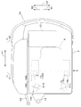
- FIG. 11 is a schematic side view showing the overall configuration of the work machine 1 according to the present embodiment.
- FIG. 12 is a schematic plan view of the work machine 1.
- a backhoe that is a turning work machine is illustrated as the work machine 1.
- the work machine 1 includes a machine body (swivel base) 2, a traveling device 3, and a work device 4.
- a cabin 5 is mounted on the body 2.
- a driver's seat 6 is provided in the cabin 5.
- the front side (in the direction of arrow A1 in FIGS. 11 and 12) of the driver (operator) seated in the driver's seat 6 of the work machine 1 is the front side, and the rear side of the driver (the arrows in FIGS. 11 and 12).
- (A2 direction) is the rear
- the left side of the driver front side in FIG. 11, the direction of arrow B1 in FIG. 12
- the right side of the driver (the back side in FIG. 11, direction of arrow B2 in FIG. 12) is the right side.
- the horizontal direction that is orthogonal to the front-rear direction K1 will be described as the body width direction K2 (see FIG. 12).
- the direction from the center in the width direction of the airframe 2 to the right or left will be described as the outside of the airframe.
- the outward direction of the aircraft is the direction in the aircraft width direction K2 and away from the center of the aircraft body 2 in the width direction.
- the direction opposite to the outside of the aircraft will be described as the inside of the aircraft.
- the in-machine direction is the direction in the body width direction K2 that approaches the center of the body 2 in the width direction.
- the traveling device 3 has a traveling body 3L provided on the left side and a traveling body 3R provided on the right side.
- the traveling body 3L and the traveling body 3R include a driving wheel 11a, a driven wheel 11b, a plurality of rolling wheels 11e, a driving wheel 11a, a driven wheel 11b, a frame 11c that rotatably supports the rolling wheels 11e, and a driving wheel.
- 11 is a crawler type traveling device having a driven wheel 11b, and a belt 11d spanned around the wheel 11e.
- the first traveling motor ML is supported on the frame 11c of the traveling body 3L, and the power of the first traveling motor ML is transmitted to the drive wheels 11a of the traveling body 3L.
- the second traveling motor MR is supported on the frame 11c of the traveling body 3R, and the power of the second traveling motor MR is transmitted to the drive wheels 11a of the traveling body 3R.
- a dozer device 7 is attached to the front portion of the traveling device 3.
- the dozer device 7 can be moved up and down (raising and lowering the blade) by expanding and contracting the dozer cylinder.
- the machine body 2 is supported on the traveling device 3 via a swing bearing 8 so as to be rotatable about a vertical axis (an axis extending in the vertical direction).
- the machine body 2 is driven to turn by a turning motor MT including a hydraulic motor (hydraulic actuator).
- the airframe 2 has a swivel substrate 9 that revolves around a vertical axis, and a weight 10.
- the swivel board 9 is made of a steel plate or the like and is connected to the swivel bearing 8.
- the weight 10 is provided at the rear part of the airframe 2.
- a motor E ⁇ b> 1 is mounted on the rear part of the body 2.
- the prime mover E1 is a diesel engine.
- the prime mover E1 may be an electric motor or a hybrid type
- the airframe 2 has a support bracket 13 at a front portion slightly to the right of the center in the airframe width direction K2.
- a swing bracket 14 is attached to the support bracket 13 so as to be swingable about the vertical axis.
- the working device 4 is attached to the swing bracket 14.
- the work device 4 includes a boom 15, an arm 16, and a bucket (work tool) 17.
- the base of the boom 15 is pivotally attached to the swing bracket 14 so as to be rotatable about a horizontal axis (an axis extending in the body width direction).
- the boom 15 can swing up and down.
- the arm 16 is pivotally attached to the distal end side of the boom 15 so as to be rotatable about a horizontal axis.
- the arm 16 can swing back and forth or up and down.
- the bucket 17 is provided on the distal end side of the arm 16 so as to be able to perform a squeeze operation and a dump operation.
- the work machine 1 can be mounted with another work tool (preliminary attachment) that can be driven by a hydraulic actuator instead of or in addition to the bucket 17.
- work tools preliminary attachments
- examples of other work tools include a hydraulic breaker, a hydraulic crusher, an angle bloom, an earth auger, a pallet fork, a sweeper, a mower, and a snow blower.
- the swing bracket 14 is swingable by expansion and contraction of a swing cylinder C2 provided in the body 2.
- the boom 15 is swingable by expansion and contraction of the boom cylinder C3.
- the arm 16 is swingable by the expansion and contraction of the arm cylinder C4.
- the bucket 17 is freely squeezed and dumped by expansion and contraction of a bucket cylinder (work implement cylinder) C5.
- the dozer cylinder, swing cylinder C2, boom cylinder C3, arm cylinder C4, and bucket cylinder C5 are constituted by hydraulic cylinders (hydraulic actuators).
- a cockpit 18 ⁇ / b> L provided in the fuselage 2 is provided on the left side of the driver's seat 6 in the cabin 5. Further, on the right side of the driver's seat 6, a cockpit 18 ⁇ / b> R provided in the fuselage 2 is also provided.
- a control device 19 is provided on the control table 18L and the control table 18R.
- the control device 19 includes a control device 19L attached to the control table 18L and a control device 19R attached to the control table 18R.
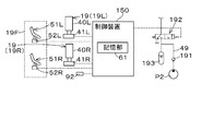
- FIG. 2 schematically shows a hydraulic circuit (hydraulic system) that operates a hydraulic actuator of the work implement.
- the hydraulic system of the work machine 1 includes a working hydraulic actuator such as a boom cylinder C3, an arm cylinder C4, a bucket cylinder C5, and a swing motor MT, a first travel motor ML, a second travel motor MR, and the like.
- a working hydraulic actuator such as a boom cylinder C3, an arm cylinder C4, a bucket cylinder C5, and a swing motor MT, a first travel motor ML, a second travel motor MR, and the like.
- This is a system for operating the traveling system hydraulic actuator.
- a circuit for controlling the dozer cylinder and the swing cylinder C2 is omitted for convenience of explanation.
- the hydraulic system of the work machine 1 includes a first hydraulic pump P1, a second hydraulic pump P2, and a plurality of control valves 33.
- the first hydraulic pump P1 is a pump that supplies hydraulic oil to the work system hydraulic actuator and the traveling system hydraulic actuator.
- the first hydraulic pump P1 is, for example, a constant capacity pump or a variable capacity pump.
- the second hydraulic pump P2 is a pump that supplies hydraulic oil for signals or control, that is, pilot oil.
- the plurality of control valves 33 are valves that control the work system hydraulic actuator and the travel system hydraulic actuator.
- a first hydraulic pump P ⁇ b> 1 is connected to the plurality of control valves 33 via an oil passage 34.
- the plurality of control valves 33 include a boom control valve 33C that controls the boom cylinder C3, an arm control valve 33D that controls the arm cylinder C4, a bucket control valve 33E that controls the bucket cylinder C5, and a swing control valve 33F that controls the swing motor MT.
- the first traveling control valve 33G for controlling the first traveling motor ML and the second traveling control valve 33H for controlling the second traveling motor MR are included.
- the boom control valve 33C is connected to the boom cylinder C3 via the oil passage 43.
- the arm control valve 33D is connected to the arm cylinder C4 via the oil passage 44.
- the bucket control valve 33E is connected to the bucket cylinder C5 through the oil passage 45.
- the turning control valve 33F is connected to the turning motor MT via the oil passage 46.
- the first travel control valve 33 ⁇ / b> G is connected to the first travel motor ML via an oil passage (first oil passage) 47.
- the second travel control valve 33H is connected to the second travel motor MR via an oil passage (second oil passage) 48.
- a boom solenoid valve 37C is connected to the pressure receiving portion of the boom control valve 33C.
- An arm electromagnetic valve 37D is connected to the pressure receiving portion of the arm control valve 33D.
- a bucket electromagnetic valve 37E is connected to the pressure receiving portion of the bucket control valve 33E.
- a swing electromagnetic valve 37F is connected to the pressure receiving portion of the swing control valve 33F.
- a forward solenoid valve 37G1 and a reverse solenoid valve 37G2 are connected to the pressure receiving portion of the first travel control valve 33G.
- a forward solenoid valve 37H1 and a reverse solenoid valve 37H2 are connected to the pressure receiving portion of the second travel control valve 33H.
- the solenoid valves 37 (37C, 37D, 37E, 37F, 37G1, 37G2, 37H1, or 37H2) are connected to the plurality of control valves 33 corresponding to the respective control valves 33.
- a second hydraulic pump P2 is connected to each solenoid valve 37 via an oil passage (pilot oil passage) 49, The pilot pressure acting on the pressure receiving portion of the control valve 33 corresponding to the electromagnetic valve 37 changes according to the opening of the electromagnetic valve 37.
- the boom control valve 33C, the arm control valve 33D, the bucket control valve 33E, the turning control valve 33F, the first travel control valve 33G, and the second travel control valve 33H are, for example, direct acting spool type switching valves.
- Each of the plurality of control valves 33 (33C, 33D, 33E, 33F, 33G, 33H) is controlled by the pilot oil acting on the pressure receiving portion via the plurality of electromagnetic valves 37 corresponding to the control valve 33.
- the direction of the hydraulic oil supplied to is switched, and the working system hydraulic actuator (boom cylinder C3, arm cylinder C4, bucket cylinder C5, swing motor MT) or traveling system hydraulic actuator (first traveling motor ML, second traveling)
- the flow rate of hydraulic oil supplied to the motor MR is controlled.
- the working system hydraulic actuator is operated by the control device 19 (control device 19L, control device 19R).
- the control device 19L includes an operation member 40L that is swingably supported by the control table 18L, and a first operation detection unit 41L that detects a swing amount of the operation member 40L.
- the operating member 40L is a lever that can swing forward, rearward, right, and left from a neutral position with respect to the control panel 18L.
- the first operation detection unit 41L is a potentiometer that detects a swing amount (operation amount) from the neutral position before, behind, right, and left of the operation member 40L.
- the operation amount and operation direction of the operation member 40L are detected by the first operation detection unit 41L, and the detected operation amount and operation direction are transferred to the control unit 60 configured by a CPU or the like. Entered.
- the control unit 60 excites the solenoid of the swing electromagnetic valve 37F connected to the pressure receiving unit of the swing control valve 33F according to the operation amount and operation direction of the operation member 40L, and controls the opening degree of the swing electromagnetic valve 37F. .
- the pilot pressure acts on the pressure receiving portion of the swing control valve 33F, the position of the swing control valve 33F is switched, and the rotation direction of the swing motor MT is switched according to the position.
- the control unit 60 determines according to the operation amount and the operation direction of the operation member 40L.
- the solenoid of the arm electromagnetic valve 37D connected to the pressure receiving portion of the arm control valve 33D is excited to control the opening degree of the arm electromagnetic valve 37D.
- the pilot pressure acts on the pressure receiving portion of the arm control valve 33D, the position of the arm control valve 33D is switched, and the arm cylinder C4 expands and contracts according to the position.
- the control device 19R includes an operation member 40R that is swingably supported by the control table 18R, and a second operation detection unit 41R that detects a swing amount of the operation member 40R.
- the operating member 40R is a lever that can swing forward, rearward, right, and left from a neutral position with respect to the control panel 18R.
- the second operation detection unit 41R is a potentiometer that detects a swing amount (operation amount) from the neutral position before, behind, right, and left of the operation member 40R.
- the operation amount and operation direction of the operation member 40R are detected by the second operation detection unit 41R, and the detected operation amount and operation direction are input to the control unit 60.
- the control unit 60 excites the solenoid of the boom electromagnetic valve 37C connected to the pressure receiving unit of the boom control valve 33C according to the operation amount and operation direction of the operation member 40R, and controls the opening degree of the boom electromagnetic valve 37C. .
- the pilot pressure acts on the pressure receiving portion of the boom control valve 33C, the position of the boom control valve 33C is switched, and the boom cylinder C3 expands and contracts according to the position.
- the operation amount and operation direction of the operation member 40R are detected by the second operation detection unit 41R, and the control unit 60 determines according to the operation amount and operation direction of the operation member 40R.
- the solenoid of the bucket electromagnetic valve 37E connected to the pressure receiving portion of the bucket control valve 33E is excited to control the opening degree of the bucket electromagnetic valve 37E.
- the pilot pressure acts on the pressure receiving portion of the bucket control valve 33E, the position of the bucket control valve 33E is switched, and the bucket cylinder C5 expands and contracts according to the position.
- the control device 19 includes a control device 19F in addition to the control device 19L and the control device 19R.
- the control device 19F is a device for operating the traveling device 3, that is, the traveling system hydraulic actuator (the first traveling motor ML and the second traveling motor MR).
- the control device 19F changes the opening of the travel control valves (the first travel control valve 33G and the second travel control valve 33R) in accordance with the operation amount with respect to the control device 19F, whereby the first travel motor ML and the second travel control valve 19F are changed. It is a device that increases or decreases the flow rate (supply amount) of hydraulic oil supplied to the travel motor MR.
- the control device 19F includes a first travel pedal (first travel operation unit) 51L, a first travel detection unit 52L, a second travel pedal (second travel operation unit) 51R, and a second travel detection. Part 52R.
- the first travel pedal 51L is a travel pedal that is disposed in front of the driver's seat 6 and on the left, and that increases or decreases the flow rate of hydraulic oil supplied by the first travel motor ML.
- the first travel pedal 51L is supported by a step or the like provided below the driver's seat 6 so as to be swingable forward and backward by a horizontal axis.
- the first travel detection unit 52L is a potentiometer that detects the swing amount (operation amount) from the neutral position before and after the first travel pedal 51L. That is, the first travel detection unit 52L detects the previous operation amount when the first travel pedal 51L swings forward. Further, the first travel detection unit 52L detects the rear operation amount when the first travel pedal 51L swings later.
- the first travel detection unit 52L is connected to the control unit 60.
- the first operation amount (previous operation amount, rear operation amount) of the first travel pedal 51L detected by the first travel detection unit 52L is input to the control unit 60.
- the control unit 60 outputs a control signal to the forward solenoid valve 37G1 or the reverse solenoid valve 37G2 according to the magnitude of the first operation amount (previous operation amount, rear operation amount), and the forward solenoid valve 37G1 or the reverse solenoid valve.
- the opening degree of 37G2 is set. Therefore, for example, when the operator depresses the first travel pedal 51L and the first operation amount as the depressing amount is detected by the first travel detecting unit 52L, the control unit 60 determines the forward electromagnetic valve 37G1 according to the depressing amount. Alternatively, the opening degree of the reverse solenoid valve 37G2 is set.
- the first travel control valve 33G opens according to the opening degree of the forward solenoid valve 37G1 or the reverse solenoid valve 37G2, and increases or decreases the flow rate of the hydraulic oil flowing from the first travel control valve 33G to the oil passage 47. That is, the flow rate of hydraulic oil supplied from the oil passage 47 to the first travel motor ML of the travel device 3 increases or decreases depending on the operation amount of the control device 19F, and the travel speed when the travel device 3 (work machine) turns left is determined. Can be changed.
- the second travel pedal 51R is a travel pedal that is arranged in front of the driver's seat 6 and on the right, and that increases or decreases the flow rate of hydraulic oil supplied to the second travel motor MR.
- the second traveling pedal 51R is supported by a step or the like provided below the driver's seat 6 so as to be swingable forward and backward by a horizontal axis.
- the second travel detection unit 52R is a potentiometer that detects a swing amount (operation amount) from a neutral position before and after the second travel pedal 51R. That is, the second travel detection unit 52R detects the previous operation amount when the second travel pedal 51R swings forward. Further, the second travel detection unit 52R detects the post-operation amount when the second travel pedal 51R swings later.
- the second traveling detection unit 52R is connected to the control unit 60.
- the second operation amount (previous operation amount, rear operation amount) of the second travel pedal 51R detected by the second travel detection unit 52R is input to the control unit 60.
- the control unit 60 outputs a control signal to the forward solenoid valve 37H1 or the reverse solenoid valve 37H2 according to the magnitude of the second operation amount (previous operation amount, rear operation amount), so that the forward solenoid valve 37H1 or the reverse solenoid valve Set the opening of 37H2. Therefore, for example, when the operator depresses the second travel pedal 51R and the second operation amount that is the depressing amount is detected by the second travel detecting unit 52R, the control unit 60 determines the forward electromagnetic valve 37H1 according to the depressing amount.
- the opening degree of the reverse solenoid valve 37H2 is set. Therefore, the second travel control valve 33H opens according to the opening degree of the forward solenoid valve 37H1 or the reverse solenoid valve 37H2, and increases or decreases the flow rate (second supply amount) of hydraulic fluid flowing from the second travel control valve 33H to the oil passage 48. Let That is, the flow rate of hydraulic oil supplied from the oil passage 48 to the second travel motor MR of the travel device 3 increases or decreases depending on the operation amount of the control device 19F, and the travel speed when the travel device 3 (work machine) turns right is determined. Can be changed.
- the control unit 60 causes the travel electromagnetic valve (advance electromagnetic valve 37G1 according to the first operation amount and the second operation amount). , 37H1, and reverse solenoid valves 37G2, 37H2).
- the control unit 60 sets the opening degrees of the forward electromagnetic valves 37G1 and 37H1 according to the operation amount that is the stepping amount.
- the control unit 60 sets the opening degree of the reverse solenoid valves 37G2 and 37H2 according to the operation amount that is the stepping amount. As a result, the flow rate of the hydraulic oil supplied to the first travel motor ML and the second travel motor MR is increased or decreased, and the travel speed at the time of reverse travel of the travel device 3 (work machine) can be changed. As shown in FIG. 2, the work machine 1 includes a steering control device (control device) 150 that controls steering and the like.
- the steering control device 150 limits the state of the work machine 1 in a steerable state in which a normal maneuvering operation of the work machine 1 by the control device 19 and a steerable operation of the work machine 1 by the steering device 19 are more limited than in a steerable state. It is a device that switches to the steering limited state. In the present embodiment, the steering operation of the work machine 1 by the steering device 19 (19F, 19L, 19R, 19F) is disabled in the steering restricted state. However, the present invention is not limited to this, and in the steering limited state, only a part of the steering operation that can be performed using the steering device 19 in the steering enabled state may not be performed.
- the steering control device 150 includes a control unit 60 and a steering switching device 110.
- the maneuver switching device 110 is a device that can be switched between a maneuverable state and a maneuver restricted state by a command (control) of the control unit 60, or can be manually switched between a maneuverable state and a maneuver restricted state.
- the control switching device 110 includes an unload valve (actuation valve) 90, a control lock switch (lock operation unit) 92, and a control lock lever (lock operation unit) 93.
- the unload valve 90 is in a supply state that enables supply of hydraulic oil to the hydraulic actuators of the work system and the traveling system, and a supply stop state that stops supply of hydraulic oil to the hydraulic actuators of the work system and the travel system.
- This is the unload valve to be switched.
- the unload valve 90 is a two-position switching valve that can be switched between a first position 90A to be in a supply state and a second position 90B to be in a supply stop state, and is a pilot oil passage 49 that supplies pilot oil. It is connected to the.
- the unload valve 90 is biased to the second position 90B by a spring 52 or the like.
- the unload valve 90 can be switched between the first position 90A and the second position 90B by operating the steering lock lever 93.
- the first position 90A is referred to as a load position
- the second position 90B is referred to as an unload position.
- the steering lock lever 93 is swingably supported on the side of the driver's seat 6 in a lowered state (lowered position) and a raised state (raised position).
- the steering lock switch 92 is a switch for manually switching between a maneuverable state and a maneuvering restricted state.
- the maneuvering lock switch 92 is provided below the steering lock lever 93.
- the steering lock switch 92 is a device that detects a state where the steering lock lever 93 is lowered (lowered position) and a state where it is raised (raised position), and the lowered position and the raised position are input to the control unit 60.
- the controller 60 excites the solenoid of the unload valve 90 and switches the unload valve 90 to the load position 90A.
- the control unit 60 demagnetizes the solenoid of the unload valve 90 and switches the unload valve 90 to the unload position 90B.
- the solenoid valves (the boom solenoid valve 37C, the arm solenoid valve 37D, the bucket solenoid valve 37E, the swing solenoid valve 37F, the forward solenoid valve 37G1, the reverse solenoid valve 37G2, and the forward solenoid valve 37H1 and the reverse solenoid valve 37H2) are no longer supplied with hydraulic oil (pilot oil), and thus cannot be operated by the control device 19 (19F, 19L, 19R, 19F) (the operation is restricted).
- the solenoid valves (the boom solenoid valve 37C, the arm solenoid valve 37D, the bucket solenoid valve 37E, the swing solenoid valve 37F, the forward solenoid valve 37G1, the reverse solenoid valve 37G2, and the forward solenoid valve 37H1). Since the hydraulic oil (pilot oil) can be supplied to the reverse solenoid valve 37H2), the steering operation by the steering device 19 (19F, 19L, 19R, 19F) can be performed, that is, the steering can be performed.
- FIG. 1 is a schematic diagram of a control block of a work machine.
- the work machine 1 includes a control unit 60, a display device 100, and an imaging device 120.
- the control unit 60, the display device 100, and the imaging device 120 can communicate with each other via an in-vehicle communication network such as CAN (Controller Area Network) or FlexRay.
- the display device 100 can perform various displays related to the work implement 1 and can perform various settings related to the work implement 1.
- the display device 100 is disposed at a position (for example, in front of the driver's seat, diagonally forward, or to the side) that is visible from an operator seated in the driver's seat in the cabin 5.
- the imaging device 120 is a camera or the like provided at the front, rear, side, or upper portion of the work machine 1, and can capture the periphery of the work device 4, the rear of the work machine 1, and the like.
- the imaging device 120 is provided in the front part of the cabin 5 and images the periphery of the boom 15, the arm 16, and the bucket (working tool) 17.
- the imaging device 120 is provided in the rear part or the rear bonnet of the cabin 5, and images the back of the rear bonnet and the periphery of the traveling device 3.
- the imaging device 120 may be provided on the side portion of the work machine 1 and the side of the machine body may be imaged.
- the control unit 60 performs various controls such as auto idle control (AI control), boom height control, and arm height control in addition to the hydraulic control described above. AI control, boom height control, and arm height control will be described.
- the control unit 60 includes a governor angle (governor position) from the governor sensor, an operation amount (angle) of the accelerator lever, an on / off signal of an idle switch (AI-SW), an engine Signals such as an engine speed, an arm angle, and a boom angle are input from the rotation sensor.
- the AI control when the control device 19 is operated, the engine speed is increased / decreased according to the operation amount of the accelerator lever, and when the control device 19 is not operated, the engine speed is fixed to an idling state. .
- the boom height control when the height of the boom 15 reaches a preset upper limit value of the boom height, the raising operation of the boom 15 is stopped regardless of the operation of the control device 19.
- the boom angle is input to the control unit 60.
- the control unit 60 stops the boom raising operation by demagnetizing the solenoid of the boom solenoid valve 37C.
- the arm angle control is to stop the scraping operation of the arm 16 regardless of the operation of the control device 19 when the arm angle reaches an upper limit value or a lower limit value of a preset arm angle (arm angle). It is. Specifically, in the arm angle control, the arm angle is input to the control unit 60 when the steering device 19 is scraping the arm 16. Then, by demagnetizing the solenoid of the arm electromagnetic valve 37D input to the control unit 60, the scraping operation of the arm 16 is stopped.
- the display device 100 includes a display unit 101 that performs display.
- the display unit 101 includes a variable display unit 101a and a fixed display unit 101b.
- the variable display unit 101a is a part whose display contents are variable, and is configured by a panel such as a liquid crystal.
- the fixed display portion 101b is a portion whose display content is fixed, and is composed of an LED or the like. In the fixed display unit 101b, the presence or absence of a warning or the like of the work machine 1 is displayed by turning on or off the LED.
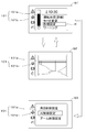
- the variable display unit 101a can display, for example, a menu screen Q1, an operation screen Q2, a setting screen Q3, and the like.
- the menu screen Q1 is a screen on which basic information is displayed. For example, items such as operation status (details), mode change, various settings, and warnings are displayed, and fuel remaining amount, time ( This is a screen for displaying (time) and the like.
- the operation screen Q2 is a screen that displays an image (peripheral image) or the like of the imaging device 120 provided in the work machine 1.
- the setting screen Q3 is a screen (input screen) that displays information necessary for performing various settings of the work machine 1 (referred to as machine settings). In the setting screen Q3, for example, information necessary for machine setting such as height control setting, AI control setting, arm limit setting, and the like is displayed.
- the display device 100 includes an input operation unit 102 for performing an input operation.
- the input operation unit 102 includes a first operation tool 111, a second operation tool 112, and a third operation tool 113.
- the first operation tool 111 is an operation tool having a rotation operation unit that performs a rotation operation and a pressing operation unit that can perform a pressing operation, and is, for example, a rotary encoder switch.
- the first operation tool 111 includes a rotation shaft 111a, a rotation operation portion (pick portion) 111b attached to the rotation shaft 111a, and a press operation portion (push switch) 111c provided on the knob portion 111b. Is included.
- the operator can perform the rotation operation by rotating the knob 111b around the rotation shaft 111b, and the position by the rotation operation is detected by the built-in encoder.
- the operator can perform a pressing operation by pressing the push switch 111c.
- the second operation tool 112 is a switch having a pressing operation unit that performs a pressing operation, and is, for example, a momentary switch.
- the third operating tool 113 is also a switch having a pressing operation unit that performs a pressing operation, for example, a momentary switch. In the second operating tool 112 and the third operating tool 113, the operator can perform a pressing operation by pressing a switch.
- the display unit 101 of the display device 100 may include a touch panel that also serves as the display and input operation unit 102, that is, a touch operation unit that receives a touch operation on the display unit 101 by an operator.
- the input operation unit 102 of the display device 100 may include any one or more of a rotation operation unit that performs a rotation operation, a press operation unit that performs a pressing operation, and a touch operation unit. It is not limited to.
- the setting screen Q3 is exemplified as the input screen of the display device 100, it may be a screen on which some input is performed on the display device 100. For example, it may be the menu screen Q1, or the menu screen Q1 and the setting screen. Both of Q3 may be included, and other screens may be included and are not limited.
- the menu screen Q1, the operation screen Q2, the setting screen Q3, and the like can be displayed, and various input operations can be performed by the input operation unit 102.
- the control unit 60 can detect an input operation performed by the input operation unit 102 described above. That is, the control unit 60 can detect a rotation operation by the first operation tool 111, a pressing operation by the first operation tool 111, a pressing operation by the second operation tool 112, and a pressing operation by the third operation tool 113.
- an operation signal (referred to as a first operation signal) indicating a rotation operation by the first operation tool 111, a pressing operation by the first operation tool 111, a pressing operation by the second operation tool 112, and a pressing operation by the third operation tool 113.
- an operation signal (second operation signal) indicating that any one of the first operation tool 111, the second operation tool 112, and the third operation tool 113 is operated is input from the display device 100 or the like.
- the control unit 60 detects an input operation by the input operation unit 102 when the first operation signal or the second operation signal is input.
- the control unit 60 executes a maneuvering switching process in which the maneuvering switching device 110 sets the maneuvering restricted state when a predetermined input operation is performed by the input operation unit 102.
- the predetermined input operation for example, declares to the work machine 1 or the like that the operator performs an input operation on the display device 100 in a situation where the display device 100 is not operated. This is an input operation.
- the predetermined input operation is an operation that first reports that the operator intends to perform the input operation continuously in a state where the operation is not performed on the display device 100.
- the control unit 60 sets the steering restriction state when a pressing operation by the push switch 111c is performed as a predetermined input operation.
- the control unit 60 In the steering switching process, when the work machine 1 is already in the steering restricted state when the push switch 111c is pressed, the control unit 60 continues to output the control signal for demagnetizing the solenoid of the unload valve 90, and the steering restricted state. To maintain.
- the control unit 60 when the push switch 111c is pressed, the control unit 60 can be steered by outputting a control signal to demagnetize the solenoid of the unload valve 90 to the unload valve 90. Switch from state to maneuver restricted state.
- control unit 60 continues the input operation by the input operation unit 102 after the start of the operation switching process, after maintaining the operation limited state, or after switching from the maneuverable state to the operation limited state. Monitor whether or not.
- the control switching device 110 before switching of the control switching device 110 before the control unit 60 shifts to the control switching processing (immediately before the start of the control switching processing), that is, before the input operation of the input operation unit 102 is detected.
- the state before switching is the state of the steering lock lever 93. As shown in FIG.
- control unit 60 includes a storage unit 61 composed of a nonvolatile memory or the like, and the storage unit 61 is in a state in which the work implement 1 can be steered as a pre-switching state. Or whether it is in a maneuvering restricted state.
- the control unit 60 When entering the return process, the control unit 60 refers to the storage unit 61 to determine whether the pre-switching state is the maneuverable state or the maneuvering restricted state. When the pre-switching state is the steerable state, in the return process, the control unit 60 causes the steering switching device 110 to switch from the steering restricted state to the steerable state. When the pre-switching state is the maneuvering restricted state, in the return process, the control unit 60 continues to output a control signal for demagnetizing the solenoid of the unload valve 90 and puts the maneuvering switching device 110 into the maneuvering restricted state. maintain.
- the operation of the push switch 111c is exemplified as the predetermined input operation in the input operation unit 102.
- the predetermined input operation is not limited to this, and as described later, a pressing operation and a rotation are performed. Either an operation or a touch operation may be used.
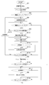
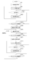
- FIG. 4A is a flowchart showing screen transitions of the menu screen Q1, the operation screen Q2, and the setting screen Q3.
- a startup screen for example, a logo
- the display device 100 displays the menu screen Q1 on the display unit 101 (S2).
- the display device 100 displays the operation screen Q2 on the display unit 101 (S4).
- the process proceeds to a process of determining whether or not the steering lock lever 93 is in a lowered state (S5: switching determination process).
- S5 switching determination process
- the display device 100 displays the menu screen Q1 on the display unit 101. (S6).
- an input operation in the input operation unit 102 (the first operation tool 111, the second operation tool 112, and the third operation tool 113) can be accepted.
- the cursor K moves, and the selection item selected by the cursor K moves.
- Candidates (referred to as selection item candidates) can be changed.
- the selection item decision operation for example, the third operation tool 113 is selected in the state where the selection item candidate is selected on the menu screen Q1, selection of “driving condition”, “mode change”, “various settings”, etc. Items can be determined. That is, the display device 100 can determine a selection item by changing a plurality of selection item candidates by performing a rotation operation with the first operation tool 111 and performing a pressing operation with the first operation tool 111. .
- the control unit 60 executes the steering switching process by interruption, and controls the steering switching device 110 to enter the steering restricted state ( S10). And if it will be in a control restriction state, display 100 will change from operation screen Q2 to menu screen Q1 (S11).
- the work implement when the operation screen Q2 is displayed and the steering lock lever 93 is lowered (Yes in S5) regardless of the start of the engine (S5, Yes), the work implement is in a steerable state. Can move.
- the operator when the operator performs a pressing operation using the push switch 111c (S9, Yes), the work implement can be changed from the maneuverable state to the maneuvering restricted state (S10). That is, when performing machine setting on the setting screen Q3, it is possible to prevent the work machine from moving more than usual by restricting the steering.
- the setting screen S3 is displayed through the pressing operation (S9, Yes) using the push switch 111c, the steering limited state can be maintained until the pressing operation (S14, Yes) using the push switch 111c is performed again.
- the display device 100 has not completed receiving input to the input operation unit, and when the second pressing operation by the push switch 111c (S14, No: second pressing operation) is executed, the display device 100 performs the input operation. Complete acceptance of input to the department.
- the control unit 60 When the control unit 60 completes reception of input to the input operation unit, the control unit 60 proceeds to a return process.
- the state before the first pressing operation by the push switch 111c (the state before switching) is the maneuverable state. If it is, the operation is switched from the operation restricted state to the maneuverable state.
- the pre-switching state is the steering restricted state, the return processing maintains the steering restricted state.
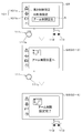
- FIG. 5 is a diagram showing screen transition for performing A1 control setting in the machine setting on the setting screen Q3.
- the AI control setting will be described with reference to FIG.
- a plurality of selection items for machine setting for example, “height control setting”, “AI control setting”, and “arm limit setting” are displayed.
- the selected selection item candidate (referred to as a selection item candidate) can be changed by moving the cursor K. it can.
- the selection item is determined.
- the setting screen Q3 is switched to the screen Q3-1 for setting the idling speed.
- the value of the idling rotational speed displayed on the screen Q3-1 can be changed (increased or decreased) by the rotation operation of the knob 111b.
- the changed idling speed value (setting value) displayed on the screen Q3-1 (setting screen Q3) is newly set to idling. It is updated as the rotation speed.
- the setting screen Q3 is switched to a screen Q3-2 indicating that the idling speed has been updated.
- FIG. 6 is a diagram showing a screen transition of arm limit setting. As shown in FIG. 6, when the cursor K is placed on the selection item candidate “arm limit setting” on the setting screen Q3 and the operator presses the third operation tool 113, the selection item is determined to be “arm limit setting”. Note that when the operation of moving the cursor K is performed, the control unit 60 has shifted to the steering switching process.
- a screen Q3-3 for instructing the position of the arm 16 to be the limit position is displayed as the setting screen Q3.
- the control unit 60 Temporarily, the control switching device 110 is switched from the control limited state to the controllable state.
- the operator After the maneuvering switching device 110 is temporarily switched to the maneuverable state, the operator operates the maneuvering device 19L to set the arm 16 to a desired limit position (upper limit position, lower limit position).
- a desired limit position upper limit position, lower limit position.
- the control unit 60 switches the control switching device 110 from the controllable state to the control limited state. Return to the control restricted state.
- the control unit 60 When the third operation tool 113 is pressed while the screen Q3-3 is displayed, the upper limit value and the lower limit value of the arm angle are updated, and the setting screen Q3 indicates that the arm limit setting has been updated. The screen is switched to the screen Q3-4 shown.
- the screen (control unit 60) of the display device 100 returns to the display of the menu screen Q1. Further, when the first operating tool 111 is pressed in the maneuvering restricted state, the control unit 60 ends the maneuvering switching process after shifting to the return process.
- the work machine 1 includes a steering device 19 that performs a steering operation on the traveling device 3, the working device 4, the turning motor MT, and the dozer device 7, a steerable state in which the steering operation by the steering device 19 is possible, A control device 150 that can be controlled to a steering restricted state that restricts a steering operation by the device 19, and a display device 100 that includes a display unit 101 and an input operation unit 102 are provided.
- the input operation for example, when the push operation by the push switch 111c is performed
- the maneuverable state is changed to the maneuvering restricted state.
- the operation of the work device 4 by the operation device 19 can be restricted.
- the work machine 1 includes an imaging device 120 that captures a peripheral image of the work machine 1, and the display device 100 causes the display unit 101 to display a peripheral image captured by the imaging device 120 when in a steerable state. Therefore, when the work device 4 is operated by the control device 19, the operator can operate the work device 4 while viewing the peripheral image of the work machine 1.
- the control device 150 enters an operation limited state and displays an input screen for performing settings related to the work implement 1 using the input operation unit on the display unit 101. Let Therefore, when the operator makes settings related to the work machine 1 using the input operation unit 102 with respect to the input screen displayed on the display unit 101, the operation of the work machine 1 by the control device 19 is automatically and reliably restricted. Can do.
- the control device 150 displays a peripheral image on the display unit 101 captured by the imaging device 120. Therefore, after the operation on the input screen is completed, the operator can quickly operate the work device 4 while confirming the peripheral image without having to bother to display the peripheral image and concentrate on the work. be able to.
- the control device 150 includes a storage unit that stores whether the maneuverable state or the maneuvering restricted state before the predetermined input operation is performed, and the control device 150 displays the display device after the predetermined input operation is performed.
- the pre-switching state is the maneuverable state
- the control is switched from the maneuvering restricted state to the maneuverable state, and if the pre-switching state is the maneuvering restricted state, the maneuvering restricted state To maintain. Therefore, after the display device 100 completes reception of the input operation unit 102, the operator can return to the pre-switching state without worrying about how the pre-switching state was.
- the control device 150 includes a lock operation unit (a steering lock switch 92 and a steering lock lever 93) for switching between a maneuverable state and a maneuvering restricted state. For this reason, the operator can easily make the steering restricted state by the lock operation unit.
- a lock operation unit (a steering lock switch 92 and a steering lock lever 93) for switching between a maneuverable state and a maneuvering restricted state. For this reason, the operator can easily make the steering restricted state by the lock operation unit.
- One or both of the steering lock switch 92 and the steering lock lever 93 may be omitted.
- the input operation unit includes at least one of a pressing operation unit that receives a pressing operation by an operator, a rotating operation tool that receives a rotating operation by the operator, and a touch operating unit that receives a touch operation on the display unit 101 by the operator. ing. For this reason, input operation with respect to the working machine 1 can be performed easily.
- the input operation unit includes a first operation tool 111 that receives a rotation operation and a pressing operation by an operator, and a second operation tool 112 and a third operation tool 113 that receive a pressing operation by the operator, and the predetermined operation is a first operation.
- the control device 150 changes the selection item candidate among the plurality of selection items displayed on the display unit 101 according to the rotation operation of the first operation tool 111, and the third operation tool 113.
- the selection item is determined by the pressing operation, and the selection item determined according to the pressing operation of the second operation tool 112 is canceled (for example, an operation for returning to the previous display screen).
- the maneuvering switching device 150 first controls the maneuvering restricted state by pressing the first operating tool 111. Can be switched to. Further, the selection item candidate that is an item of machine setting can be easily changed by the first operation tool 111 with the rotary encoder. Further, the selection item candidates can be easily determined by the third operation tool 113 that performs a pressing operation different from that of the first operation tool 111. Further, the selected selection item can be easily canceled (for example, an operation for returning to the previous display screen) by a pressing operation of the second operation tool 112 different from the third operation tool 113.
- FIG. 4B shows a modification of FIG. 4A.
- S1 to S6 and S8 to S15 are the same as FIG. 4A.
- the control unit 60 proceeds to a determination of whether or not the pressing operation by the push switch 111c is not performed in the state where the menu screen Q1 is displayed (S6) (S16).
- S16, Yes the pressing operation by the push switch 111c is performed
- the process proceeds to determination of whether or not the determining operation has been performed (S17), and after the determining operation (S17, Yes), the setting screen Q3 is displayed. (S8). That is, in FIG.
- FIG. 7 shows a control block of the work machine in the second embodiment
- FIG. 8 shows a hydraulic system of the work machine in the second embodiment.
- the operation switching device 110 unload valve 90
- the second embodiment Is an embodiment in which the steering is electrically restricted without using the unload valve 90.
- the control device 150 is a device composed of a CPU or the like, and a plurality of electromagnetic valves 37C, 37D, 37E, 37F, 37G1, 37G2, 37H1, and 37H2 are connected. .
- the control device 150 can perform various controls such as hydraulic control, auto idle control (AI control), boom height control, arm height control, and the like, similar to the control unit 60 shown in the first embodiment. is there.
- the control device 150 executes a steering switching process.
- the control device 150 operates the control device 19L, the control device 19R, and the control device 19F to demagnetize the electromagnetic valve even when the operation amount of the control device is input. Does not accept operations from the device.
- the control device 150 operates the control device 19L, the control device 19R, and the control device 19F in a state where the control switching process is not being executed, and when the operation amount of the control device is input, The operation is accepted, and the solenoid valve is controlled based on the operation amount of the control device.
- the control device 150 by configuring the control device 150 with a CPU or the like, it is possible to electrically switch between the maneuverable state and the maneuvering restricted state, and the input operation unit 102 performs a predetermined input operation. When it is broken, it can be in a restricted operation state.
- a steering lock switch (lock operation unit) 92 for manually switching between a steerable state and a steering restricted state.
- the steering lock switch 92 may be a changeover switch that can be directly operated by an operator, or may be a switch that detects the swing of the steering lock lever 93 as shown in the first embodiment.
- FIG. 10 is a flowchart showing screen transitions of the menu screen, the operation screen, and the setting screen in the third embodiment.
- the work machine 1 includes the steering lock switch 92 and the steering lock lever 93.
- the working machine 1 does not use the steering lock switch 92 and the steering lock lever 93.
- the steering lock switch 92 and the steering lock lever 93 are combined with a push switch 111c.
- reporting part for example, lamp
- a startup screen is displayed on the display unit 101 of the display device 100 (S1). Then, the display device 100 displays the menu screen Q1 on the display unit 101 (S2). When the menu screen Q1 is displayed on the display unit 101 (S2) and a determination operation is performed (S21, Yes), the display device 100 displays the setting screen Q3 on the display unit 101 (S22). Further, in the state where the menu screen Q1 is displayed (S2), when the determination operation of “various settings” is not performed (S21, No), the process proceeds to the determination of whether or not the pressing operation by the push switch 111c is performed. (S23).
- the control unit 60 determines whether or not a pressing operation by the push switch 111c, which is a predetermined input operation, has been performed in a state where the operation screen Q2 is displayed (S25) (S26).
- the push switch 111c is not pressed (S26, No)
- the display of the operation screen Q2 is maintained.
- the control unit 60 executes a steering switching process by interruption and controls the steering switching device 110 to be in a steering limited state (S27).
- the lamp is turned on (ON) to notify that the work implement can be controlled.
- S27 and subsequent steps are the same as S11 to S15 in FIG. 4A.
- the lamp is turned off (OFF) to notify that the work machine is steerable.
Landscapes
- Engineering & Computer Science (AREA)
- Mining & Mineral Resources (AREA)
- Civil Engineering (AREA)
- General Engineering & Computer Science (AREA)
- Structural Engineering (AREA)
- Mechanical Engineering (AREA)
- Operation Control Of Excavators (AREA)
- Multimedia (AREA)
- Component Parts Of Construction Machinery (AREA)
Abstract
表示装置への入力操作を簡単に行うことができるようにする。 作業機は、操縦操作を行う操縦装置を備えた作業機であって、当該作業機を操縦操作が可能な操縦可能状態と操縦装置による操縦操作が操縦可能状態よりも制限される操縦制限状態とに制御可能な制御装置と、表示部と入力操作部とを有する表示装置と、を備え、制御装置は、入力操作部で所定の入力操作が行われた際に操縦制限状態にすることを特徴とする。作業機は、作業機の周辺画像を撮像する撮像装置を備え、表示装置は、操縦可能状態であるときには表示部に撮像装置が撮像した前記周辺画像を表示させる。
Description
本発明は、例えば、バックホー等の作業機に関する。
従来、特許文献1に開示された作業機が知られている。
特許文献1に開示された作業機は、表示装置に対する入力操作を行うことによって、作業機の設定を行うことができる。
特許文献1に開示された作業機は、表示装置に対する入力操作を行うことによって、作業機の設定を行うことができる。
しかしながら、特許文献1では、表示装置に対する入力操作中の作業機の動作制限については考慮されていない。
そこで本発明は、上記課題に鑑み、表示装置への入力操作中に作業機の動作制限を簡単に行うことができる作業機を提供することを目的とする。
そこで本発明は、上記課題に鑑み、表示装置への入力操作中に作業機の動作制限を簡単に行うことができる作業機を提供することを目的とする。
本発明の一態様に係る作業機は、操縦操作を行う操縦装置を備えた作業機であって、当該作業機を前記操縦操作が可能な操縦可能状態と前記操縦装置による操縦操作が前記操縦可能状態よりも制限される操縦制限状態とに制御可能な制御装置と、表示部と入力操作部とを有する表示装置と、を備え、前記制御装置は、前記入力操作部で所定の入力操作が行われた際に前記操縦制限状態にする。
本発明によれば、表示装置への入力操作中に作業機の動作制限を簡単に行うことができる。
以下、本発明の一実施形態について、図面を適宜参照しつつ説明する。
[第1実施形態]
図11は、本実施形態に係る作業機1の全体構成を示す概略側面図である。図12は、作業機1の概略平面図である。本実施形態では、作業機1として旋回作業機であるバックホーが例示されている。
[第1実施形態]
図11は、本実施形態に係る作業機1の全体構成を示す概略側面図である。図12は、作業機1の概略平面図である。本実施形態では、作業機1として旋回作業機であるバックホーが例示されている。
先ず、作業機1の全体構成を説明する。
図11、図12に示すように、作業機1は、機体(旋回台)2と、走行装置3と、作業装置4とを備えている。機体2上にはキャビン5が搭載されている。キャビン5の室内には運転席6が設けられている。
本実施形態においては、作業機1の運転席6に着座した運転者(オペレータ)の前側(図11、図12の矢印A1方向)を前方、運転者の後側(図11、図12の矢印A2方向)を後方、運転者の左側(図11の手前側、図12の矢印B1方向)を左方、運転者の右側(図11の奥側、図12の矢印B2方向)を右方として説明する。
図11、図12に示すように、作業機1は、機体(旋回台)2と、走行装置3と、作業装置4とを備えている。機体2上にはキャビン5が搭載されている。キャビン5の室内には運転席6が設けられている。
本実施形態においては、作業機1の運転席6に着座した運転者(オペレータ)の前側(図11、図12の矢印A1方向)を前方、運転者の後側(図11、図12の矢印A2方向)を後方、運転者の左側(図11の手前側、図12の矢印B1方向)を左方、運転者の右側(図11の奥側、図12の矢印B2方向)を右方として説明する。
また、前後方向K1に直交する方向である水平方向を機体幅方向K2(図12参照)として説明する。機体2の幅方向の中央部から右部、或いは、左部へ向かう方向を機体外方として説明する。言い換えれば、機体外方とは、機体幅方向K2であって機体2の幅方向の中心から離れる方向のことである。機体外方とは反対の方向を、機体内方として説明する。言い換えれば、機体内方とは、機体幅方向K2であって機体2の幅方向の中心に近づく方向である。
図11に示すように、走行装置3は、左側に設けられた走行体3Lと、右側に設けられた走行体3Rとを有する。走行体3L及び走行体3Rは、駆動輪11aと、従動輪11bと、複数の転輪11eと、駆動輪11a、従動輪11b、及び転輪11eを回転自在に支持するフレーム11cと、駆動輪11a、従動輪11b、及び転輪11eに架け渡されたベルト11dとを有するクローラ式の走行装置である。走行体3Lのフレーム11cには、第1走行モータMLが支持されており、第1走行モータMLの動力が走行体3Lの駆動輪11aに伝達される。走行体3Rのフレーム11cには、第2走行モータMRが支持されており、第2走行モータMRの動力が走行体3Rの駆動輪11aに伝達される。
走行装置3の前部には、ドーザ装置7が装着されている。ドーザ装置7は、ドーザシリンダを伸縮することにより昇降(ブレードを上げ下げ)させることができる。
機体2は、走行装置3上に旋回ベアリング8を介して縦軸(上下の方向に延伸する軸心)回りに旋回自在に支持されている。機体2は、油圧モータ(油圧アクチュエータ)からなる旋回モータMTによって旋回駆動される。機体2は、縦軸回りに旋回する旋回基板9と、ウエイト10とを有している。旋回基板9は、鋼板等から形成されており、旋回ベアリング8に連結されている。ウエイト10は、機体2の後部に設けられている。機体2の後部には、原動機E1が搭載されている。原動機E1は、ディーゼルエンジンである。なお、原動機E1は、電動モータであってもよいし、ディーゼルエンジン及び電動モータを有するハイブリッド型であってもよい。
機体2は、走行装置3上に旋回ベアリング8を介して縦軸(上下の方向に延伸する軸心)回りに旋回自在に支持されている。機体2は、油圧モータ(油圧アクチュエータ)からなる旋回モータMTによって旋回駆動される。機体2は、縦軸回りに旋回する旋回基板9と、ウエイト10とを有している。旋回基板9は、鋼板等から形成されており、旋回ベアリング8に連結されている。ウエイト10は、機体2の後部に設けられている。機体2の後部には、原動機E1が搭載されている。原動機E1は、ディーゼルエンジンである。なお、原動機E1は、電動モータであってもよいし、ディーゼルエンジン及び電動モータを有するハイブリッド型であってもよい。
機体2は、機体幅方向K2の中央のやや右寄りの前部に支持ブラケット13を有している。支持ブラケット13には、スイングブラケット14が、縦軸回りに揺動自在に取り付けられている。スイングブラケット14には、作業装置4が取り付けられている。
図11に示すように、作業装置4は、ブーム15と、アーム16と、バケット(作業具)17とを有している。ブーム15の基部は、スイングブラケット14に横軸(機体幅方向に延伸する軸心)回りに回動自在に枢着されている。これによって、ブーム15が上下に揺動自在とされている。アーム16は、ブーム15の先端側に横軸回りに回動自在に枢着されている。これによって、アーム16が前後或いは上下に揺動自在とされている。バケット17は、アーム16の先端側にスクイ動作及びダンプ動作可能に設けられている。作業機1は、バケット17に代えて或いは加えて、油圧アクチュエータにより駆動可能な他の作業具(予備アタッチメント)を装着することが可能である。他の作業具(予備アタッチメント)としては、油圧ブレーカ、油圧圧砕機、アングルブルーム、アースオーガ、パレットフォーク、スイーパー、モア、スノウブロア等が例示できる。
図11に示すように、作業装置4は、ブーム15と、アーム16と、バケット(作業具)17とを有している。ブーム15の基部は、スイングブラケット14に横軸(機体幅方向に延伸する軸心)回りに回動自在に枢着されている。これによって、ブーム15が上下に揺動自在とされている。アーム16は、ブーム15の先端側に横軸回りに回動自在に枢着されている。これによって、アーム16が前後或いは上下に揺動自在とされている。バケット17は、アーム16の先端側にスクイ動作及びダンプ動作可能に設けられている。作業機1は、バケット17に代えて或いは加えて、油圧アクチュエータにより駆動可能な他の作業具(予備アタッチメント)を装着することが可能である。他の作業具(予備アタッチメント)としては、油圧ブレーカ、油圧圧砕機、アングルブルーム、アースオーガ、パレットフォーク、スイーパー、モア、スノウブロア等が例示できる。
スイングブラケット14は、機体2内に備えられたスイングシリンダC2の伸縮によって揺動自在とされている。ブーム15は、ブームシリンダC3の伸縮によって揺動自在とされている。アーム16は、アームシリンダC4の伸縮によって揺動自在とされている。バケット17は、バケットシリンダ(作業具シリンダ)C5の伸縮によってスクイ動作及びダンプ動作自在とされている。ドーザシリンダ、スイングシリンダC2、ブームシリンダC3、アームシリンダC4、バケットシリンダC5は、油圧シリンダ(油圧アクチュエータ)によって構成されている。
図12に示すように、キャビン5内の運転席6の左側には、機体2に設けられた操縦台18Lが設けられている。また、運転席6の右側にも、機体2に設けられた操縦台18Rが設けられている。操縦台18L及び操縦台18Rには、操縦装置19が設けられている。操縦装置19は、操縦台18Lに取り付けられた操縦装置19Lと、操縦台18Rに取り付けられた操縦装置19Rと、を有している。
図2は、作業機の油圧アクチュエータを作動させる油圧回路(油圧システム)の概略を示している。
図2に示すように、作業機1の油圧システムは、ブームシリンダC3、アームシリンダC4、バケットシリンダC5、旋回モータMT等の作業系油圧アクチュエータと、第1走行モータML、第2走行モータMR等の走行系油圧アクチュエータとを作動させるシステムである。なお、図2の油圧システムは、説明の便宜上、ドーザシリンダ及びスイングシリンダC2を制御する回路を省略している。
図2に示すように、作業機1の油圧システムは、ブームシリンダC3、アームシリンダC4、バケットシリンダC5、旋回モータMT等の作業系油圧アクチュエータと、第1走行モータML、第2走行モータMR等の走行系油圧アクチュエータとを作動させるシステムである。なお、図2の油圧システムは、説明の便宜上、ドーザシリンダ及びスイングシリンダC2を制御する回路を省略している。
作業機1の油圧システムは、第1油圧ポンプP1と、第2油圧ポンプP2と、複数の制御弁33を有している。第1油圧ポンプP1は、作業系油圧アクチュエータ及び走行系油圧アクチュエータに作動油を供給するポンプである。第1油圧ポンプP1は、例えば、定容量ポンプ、或いは、可変容量ポンプである。また、第2油圧ポンプP2は、信号用又は制御用等の作動油、即ち、パイロット油を供給するポンプである。複数の制御弁33は、作業系油圧アクチュエータ、走行系油圧アクチュエータを制御する弁である。複数の制御弁33には、油路34を介して第1油圧ポンプP1が接続されている。
複数の制御弁33は、ブームシリンダC3を制御するブーム制御弁33C、アームシリンダC4を制御するアーム制御弁33D、バケットシリンダC5を制御するバケット制御弁33E、旋回モータMTを制御する旋回制御弁33F、第1走行モータMLを制御する第1走行制御弁33G、第2走行モータMRを制御する第2走行制御弁33Hを含んでいる。
ブーム制御弁33Cは、油路43を介してブームシリンダC3に接続されている。アーム制御弁33Dは、油路44を介してアームシリンダC4に接続されている。バケット制御弁33Eは、油路45を介してバケットシリンダC5に接続されている。旋回制御弁33Fは、油路46を介して旋回モータMTに接続されている。第1走行制御弁33Gは、油路(第1油路)47を介して第1走行モータMLに接続されている。第2走行制御弁33Hは、油路(第2油路)48を介して第2走行モータMRに接続されている。
ブーム制御弁33Cの受圧部には、ブーム電磁弁37Cが接続されている。アーム制御弁33Dの受圧部には、アーム電磁弁37Dが接続されている。バケット制御弁33Eの受圧部には、バケット電磁弁37Eが接続されている。旋回制御弁33Fの受圧部には、旋回電磁弁37Fが接続されている。第1走行制御弁33Gの受圧部には、前進電磁弁37G1及び後進電磁弁37G2が接続されている。第2走行制御弁33Hの受圧部には、前進電磁弁37H1及び後進電磁弁37H2が接続されている。
即ち、複数の制御弁33には、それぞれの制御弁33に対応して、電磁弁37(37C、37D、37E、37F、37G1、37G2、37H1、あるいは、37H2)が接続されている。各電磁弁37には、油路(パイロット油路)49を介して第2油圧ポンプP2が接続され、
当該電磁弁37の開度に応じて当該電磁弁37に対応する制御弁33の受圧部に作用するパイロット圧が変化する。
当該電磁弁37の開度に応じて当該電磁弁37に対応する制御弁33の受圧部に作用するパイロット圧が変化する。
ブーム制御弁33C、アーム制御弁33D、バケット制御弁33E、旋回制御弁33F、第1走行制御弁33G、第2走行制御弁33Hは、例えば、直動スプール形の切換弁である。複数の制御弁33(33C、33D、33E、33F、33G、33H)のそれぞれは、当該制御弁33に対応する複数の電磁弁37を介して受圧部に作用するパイロット油によって、当該制御弁33に供給された作動油の方向等を切り換え、作業系油圧アクチュエータ(ブームシリンダC3、アームシリンダC4、バケットシリンダC5、旋回モータMT)、或いは、走行系油圧アクチュエータ(第1走行モータML、第2走行モータMR)に供給される作動油の流量等を制御する。
作業系油圧アクチュエータは、操縦装置19(操縦装置19L、操縦装置19R)によって操作される。操縦装置19Lは、操縦台18Lに揺動自在に支持された操作部材40Lと、操作部材40Lの揺動量を検出する第1操作検出部41Lとを有している。操作部材40Lは、操縦台18Lに対して中立位置から、前、後、右、左に揺動自在なレバーである。第1操作検出部41Lは、操作部材40Lの前、後、右、左の中立位置からの揺動量(操作量)を検出するポテンションメータである。
操作部材40Lをオペレータ等が操作すると、操作部材40Lの操作量及び操作方向が第1操作検出部41Lにより検出され、検出された操作量及び操作方向は、CPU等から構成された制御部60に入力される。制御部60は、操作部材40Lの操作量及び操作方向に応じて、旋回制御弁33Fの受圧部に接続された旋回電磁弁37Fのソレノイドを励磁し、当該旋回電磁弁37Fの開度を制御する。その結果、旋回制御弁33Fの受圧部にパイロット圧が作用し、当該旋回制御弁33Fの位置が切り換えられ、当該位置に応じて旋回モータMTの回転方向が切り換えられる。
また、操作部材40Lをオペレータ等が操作すると、操作部材40Lの操作量及び操作方向が第1操作検出部41Lにより検出され、制御部60は、操作部材40Lの操作量及び操作方向に応じて、アーム制御弁33Dの受圧部に接続されたアーム電磁弁37Dのソレノイドを励磁し、当該アーム電磁弁37Dの開度を制御する。その結果、アーム制御弁33Dの受圧部にパイロット圧が作用し、当該アーム制御弁33Dの位置が切り換えられ、位置に応じてアームシリンダC4が伸縮する。
操縦装置19Rは、操縦台18Rに揺動自在に支持された操作部材40Rと、操作部材40Rの揺動量を検出する第2操作検出部41Rとを有している。操作部材40Rは、操縦台18Rに対して中立位置から、前、後、右、左に揺動自在なレバーである。第2操作検出部41Rは、操作部材40Rの前、後、右、左の中立位置からの揺動量(操作量)を検出するポテンションメータである。
操作部材40Rをオペレータ等が操作すると、操作部材40Rの操作量及び操作方向が第2操作検出部41Rにより検出され、検出された操作量及び操作方向は制御部60に入力される。制御部60は、操作部材40Rの操作量及び操作方向に応じて、ブーム制御弁33Cの受圧部に接続されたブーム電磁弁37Cのソレノイドを励磁し、当該ブーム電磁弁37Cの開度を制御する。その結果、ブーム制御弁33Cの受圧部にパイロット圧が作用し、当該ブーム制御弁33Cの位置が切り換えられ、当該位置に応じてブームシリンダC3が伸縮する。
また、操作部材40Rをオペレータ等が操作すると、操作部材40Rの操作量及び操作方向が第2操作検出部41Rにより検出され、制御部60は、操作部材40Rの操作量及び操作方向に応じて、バケット制御弁33Eの受圧部に接続されたバケット電磁弁37Eのソレノイドを励磁し、当該バケット電磁弁37Eの開度を制御する。その結果、バケット制御弁33Eの受圧部にパイロット圧が作用し、当該バケット制御弁33Eの位置が切り換えられ、位置に応じてバケットシリンダC5が伸縮する。
以上のように、操縦装置19L及び操縦装置19Rを操作することによって、機体2、ブーム15、アーム16、バケット(作業具)17を操作することができる。
さて、操縦装置19は、操縦装置19L及び操縦装置19Rの他に、操縦装置19Fを備えている。操縦装置19Fは、走行装置3、即ち、走行系油圧アクチュエータ(第1走行モータML及び第2走行モータMR)を操作するための装置である。操縦装置19Fは、当該操縦装置19Fに対する操作量に応じて走行制御弁(第1走行制御弁33G、第2走行制御弁33R)の開度を変更することにより、第1走行モータML及び第2走行モータMRに供給する作動油の流量(供給量)を増減させる装置である。
さて、操縦装置19は、操縦装置19L及び操縦装置19Rの他に、操縦装置19Fを備えている。操縦装置19Fは、走行装置3、即ち、走行系油圧アクチュエータ(第1走行モータML及び第2走行モータMR)を操作するための装置である。操縦装置19Fは、当該操縦装置19Fに対する操作量に応じて走行制御弁(第1走行制御弁33G、第2走行制御弁33R)の開度を変更することにより、第1走行モータML及び第2走行モータMRに供給する作動油の流量(供給量)を増減させる装置である。
具体的には、操縦装置19Fは、第1走行ペダル(第1走行操作部)51Lと、第1走行検出部52Lと、第2走行ペダル(第2走行操作部)51Rと、第2走行検出部52Rとを有している。
第1走行ペダル51Lは、運転席6の前方で且つ左に配置され、且つ、第1走行モータMLの供給する作動油の流量を増減させる走行ペダルである。第1走行ペダル51Lは、運転席6の下部に設けられたステップ等に横軸によって、前、後に揺動自在に支持されている。
第1走行ペダル51Lは、運転席6の前方で且つ左に配置され、且つ、第1走行モータMLの供給する作動油の流量を増減させる走行ペダルである。第1走行ペダル51Lは、運転席6の下部に設けられたステップ等に横軸によって、前、後に揺動自在に支持されている。
第1走行検出部52Lは、第1走行ペダル51Lの前、後の中立位置からの揺動量(操作量)を検出するポテンションメータである。即ち、第1走行検出部52Lは、第1走行ペダル51Lが前に揺動した場合は、前操作量を検出する。また、第1走行検出部52Lは、第1走行ペダル51Lが後に揺動した場合は、後操作量を検出する。
第1走行検出部52Lは、制御部60に接続されている。第1走行検出部52Lによって検出された第1走行ペダル51Lの第1操作量(前操作量、後操作量)は、制御部60に入力される。
第1走行検出部52Lは、制御部60に接続されている。第1走行検出部52Lによって検出された第1走行ペダル51Lの第1操作量(前操作量、後操作量)は、制御部60に入力される。
制御部60は、第1操作量(前操作量、後操作量)の大きさに応じて、前進電磁弁37G1又は後進電磁弁37G2に制御信号を出力して、前進電磁弁37G1又は後進電磁弁37G2の開度を設定する。したがって、第1走行ペダル51Lを、例えば、オペレータが踏み込み、踏み込み量である第1操作量が第1走行検出部52Lによって検出されると、制御部60は、踏み込み量に応じて前進電磁弁37G1又は後進電磁弁37G2の開度を設定する。そのため、第1走行制御弁33Gは前進電磁弁37G1又は後進電磁弁37G2の開度に応じて開き、第1走行制御弁33Gから油路47に流れる作動油の流量を増減させる。即ち、操縦装置19Fの操作量によって、油路47から走行装置3の第1走行モータMLに供給する作動油の流量が増減し、走行装置3(作業機)が左に曲がる際の走行速度を変更することができる。
第2走行ペダル51Rは、運転席6の前方で且つ右に配置され、且つ、第2走行モータMRに供給する作動油の流量を増減させる走行ペダルである。第2走行ペダル51Rは、運転席6の下部に設けられたステップ等に横軸によって、前、後に揺動自在に支持されている。
第2走行検出部52Rは、第2走行ペダル51Rの前、後の中立位置からの揺動量(操作量)を検出するポテンションメータである。即ち、第2走行検出部52Rは、第2走行ペダル51Rが前に揺動した場合は、前操作量を検出する。また、第2走行検出部52Rは、第2走行ペダル51Rが後に揺動した場合は、後操作量を検出する。
第2走行検出部52Rは、第2走行ペダル51Rの前、後の中立位置からの揺動量(操作量)を検出するポテンションメータである。即ち、第2走行検出部52Rは、第2走行ペダル51Rが前に揺動した場合は、前操作量を検出する。また、第2走行検出部52Rは、第2走行ペダル51Rが後に揺動した場合は、後操作量を検出する。
第2走行検出部52Rは、制御部60に接続されている。第2走行検出部52Rによって検出された第2走行ペダル51Rの第2操作量(前操作量、後操作量)は、制御部60に入力される。
制御部60は、第2操作量(前操作量、後操作量)の大きさに応じて、前進電磁弁37H1又は後進電磁弁37H2に制御信号を出力して、前進電磁弁37H1又は後進電磁弁37H2の開度を設定する。したがって、第2走行ペダル51Rを、例えば、オペレータが踏み込み、踏み込み量である第2操作量が第2走行検出部52Rによって検出されると、制御部60は、踏み込み量に応じて前進電磁弁37H1又は後進電磁弁37H2の開度を設定する。そのため、第2走行制御弁33Hは前進電磁弁37H1又は後進電磁弁37H2の開度に応じて開き、第2走行制御弁33Hから油路48に流れる作動油の流量(第2供給量)を増減させる。即ち、操縦装置19Fの操作量によって、油路48から走行装置3の第2走行モータMRに供給する作動油の流量が増減し、走行装置3(作業機)が右に曲がる際の走行速度を変更することができる。
制御部60は、第2操作量(前操作量、後操作量)の大きさに応じて、前進電磁弁37H1又は後進電磁弁37H2に制御信号を出力して、前進電磁弁37H1又は後進電磁弁37H2の開度を設定する。したがって、第2走行ペダル51Rを、例えば、オペレータが踏み込み、踏み込み量である第2操作量が第2走行検出部52Rによって検出されると、制御部60は、踏み込み量に応じて前進電磁弁37H1又は後進電磁弁37H2の開度を設定する。そのため、第2走行制御弁33Hは前進電磁弁37H1又は後進電磁弁37H2の開度に応じて開き、第2走行制御弁33Hから油路48に流れる作動油の流量(第2供給量)を増減させる。即ち、操縦装置19Fの操作量によって、油路48から走行装置3の第2走行モータMRに供給する作動油の流量が増減し、走行装置3(作業機)が右に曲がる際の走行速度を変更することができる。
また、第1走行ペダル51L及び第2走行ペダル51Rを前進側又は後進側に同時に操作すれば、制御部60は、第1操作量及び第2操作量に応じて走行電磁弁(前進電磁弁37G1、37H1、後進電磁弁37G2、37H2)の開度を設定する。例えば、第1走行ペダル51L及び第2走行ペダル51Rを前側に踏み込めば、制御部60は、踏み込み量である操作量に応じて、前進電磁弁37G1、37H1の開度を設定する。その結果、第1走行モータML及び第2走行モータMRに供給する作動油の流量が増減し、走行装置3(作業機)の前進時の走行速度を変更することができる。
一方、第1走行ペダル51L及び第2走行ペダル51Rを後側に踏み込めば、制御部60は、踏み込み量である操作量に応じて、後進電磁弁37G2、37H2の開度を設定する。その結果、第1走行モータML及び第2走行モータMRに供給する作動油の流量が増減し、走行装置3(作業機)の後進時の走行速度を変更することができる。
図2に示すように、作業機1は、操縦等の制御を行う操縦制御装置(制御装置)150を備えている。操縦制御装置150は、作業機1の状態を、操縦装置19による作業機1の通常の操縦操作が可能な操縦可能状態と、操縦装置19による作業機1の操縦操作が操縦可能状態よりも制限される操縦制限状態とに切り換える装置である。本実施形態では、操縦制限状態において操縦装置19(19F、19L、19R、19F)による作業機1の操縦操作をできなくする。ただし、これに限らず、操縦制限状態において、操縦可能状態で操縦装置19を用いて行うことのできる操縦操作のうちの一部のみを行えないようにしてもよい。
図2に示すように、作業機1は、操縦等の制御を行う操縦制御装置(制御装置)150を備えている。操縦制御装置150は、作業機1の状態を、操縦装置19による作業機1の通常の操縦操作が可能な操縦可能状態と、操縦装置19による作業機1の操縦操作が操縦可能状態よりも制限される操縦制限状態とに切り換える装置である。本実施形態では、操縦制限状態において操縦装置19(19F、19L、19R、19F)による作業機1の操縦操作をできなくする。ただし、これに限らず、操縦制限状態において、操縦可能状態で操縦装置19を用いて行うことのできる操縦操作のうちの一部のみを行えないようにしてもよい。
操縦制御装置150は、制御部60と、操縦切換装置110とを含んでいる。操縦切換装置110は、制御部60の指令(制御)によって操縦可能状態と操縦制限状態とに切り換えたり、手動によって操縦可能状態と操縦制限状態とに切り換えることができる装置である。操縦切換装置110は、アンロード弁(作動弁)90と、操縦ロックスイッチ(ロック操作部)92と、操縦ロックレバー(ロック操作部)93とを有している。
アンロード弁90は、作業系及び走行系の油圧アクチュエータへの作動油の供給を可能にする供給状態と、作業系及び走行系の油圧アクチュエータへの作動油の供給を停止する供給停止状態とに切り換えるアンロード弁である。詳しくは、アンロード弁90は、供給状態にする第1位置90Aと、供給停止状態にする第2位置90Bとに切換可能な2位置切換弁であって、パイロット油を供給するパイロット油路49に接続されている。アンロード弁90は、バネ52等によって第2位置90Bに付勢されている。アンロード弁90は、操縦ロックレバー93の操作によって第1位置90A及び第2位置90Bに切り換え自在である。説明の便宜上、第1位置90Aをロード位置、第2位置90Bをアンロード位置という。
操縦ロックレバー93は、運転席6の側方において、下げた状態(下げ位置)と上げた状態(上げ位置)とに揺動自在に支持されている。操縦ロックスイッチ92は、手動により操縦可能状態と操縦制限状態とに切り換えるためのスイッチであって、例えば、操縦ロックレバー93の下部に設けられている。この場合、操縦ロックスイッチ92は、操縦ロックレバー93を下げた状態(下げ位置)と上げた状態(上げ位置)とを検出する装置で、下げ位置及び上げ位置は制御部60に入力される。制御部60は、下げ位置が入力されると、アンロード弁90のソレノイドを励磁して、当該アンロード弁90をロード位置90Aに切り換える。制御部60は、上げ位置が入力されると、アンロード弁90のソレノイドを消磁して、当該アンロード弁90をアンロード位置90Bに切り換える。
したがって、アンロード弁90がアンロード位置である場合、電磁弁(ブーム電磁弁37C、アーム電磁弁37D、バケット電磁弁37E、旋回電磁弁37F、前進電磁弁37G1、後進電磁弁37G2、前進電磁弁37H1、後進電磁弁37H2)に作動油(パイロット油)が供給されなくなるため、操縦装置19(19F、19L、19R、19F)による操縦操作ができなくなる(操縦制限状態になる)。一方、アンロード弁90がロード位置である場合、電磁弁(ブーム電磁弁37C、アーム電磁弁37D、バケット電磁弁37E、旋回電磁弁37F、前進電磁弁37G1、後進電磁弁37G2、前進電磁弁37H1、後進電磁弁37H2)に作動油(パイロット油)が供給できるため、操縦装置19(19F、19L、19R、19F)による操縦操作が可能になる、即ち、操縦可能状態にすることができる。
図1は、作業機の制御ブロックの概略図をしている。図1に示すように、作業機1は、制御部60と、表示装置100と、撮像装置120とを備えている。制御部60、表示装置100及び撮像装置120は、CAN(Controller Area Network)やフレックスレイ(FlexRay)等の車載用通信ネットワークによって、相互通信が可能である。
表示装置100は、作業機1に関する様々な表示を行ったり、作業機1に関する様々な設定を行うことが可能である。表示装置100は、キャビン5の室内における運転席に着座したオペレータから視認可能な位置(例えば、運転席の前方、斜め前方、或いは側方)に配置されている。撮像装置120は、作業機1の前部、後部、側部或いは上部に設けられたカメラ等であって、作業装置4の周辺、作業機1の後方等を撮像することが可能である。例えば、撮像装置120は、キャビン5の前部に設けられていて、ブーム15、アーム16、バケット(作業具)17の周辺を撮像する。また、撮像装置120は、キャビン5の後部或いは後部ボンネットに設けられていて、後部ボンネットの後方、走行装置3の周辺を撮像する。或いは、撮像装置120を作業機1の側部に備え、機体側方を撮像するようにしてもよい。
表示装置100は、作業機1に関する様々な表示を行ったり、作業機1に関する様々な設定を行うことが可能である。表示装置100は、キャビン5の室内における運転席に着座したオペレータから視認可能な位置(例えば、運転席の前方、斜め前方、或いは側方)に配置されている。撮像装置120は、作業機1の前部、後部、側部或いは上部に設けられたカメラ等であって、作業装置4の周辺、作業機1の後方等を撮像することが可能である。例えば、撮像装置120は、キャビン5の前部に設けられていて、ブーム15、アーム16、バケット(作業具)17の周辺を撮像する。また、撮像装置120は、キャビン5の後部或いは後部ボンネットに設けられていて、後部ボンネットの後方、走行装置3の周辺を撮像する。或いは、撮像装置120を作業機1の側部に備え、機体側方を撮像するようにしてもよい。
制御部60は、上述した油圧制御の他に、オートアイドル制御(AI制御)、ブーム高さ制御、アーム高さ制御などの様々な制御を行う。AI制御、ブーム高さ制御及びアーム高さ制御について説明する。
制御部60には、操縦装置19の操作量の他に、ガバナセンサからのガバナ角度(ガバナ位置)、アクセルレバーの操作量(角度)、アイドルスイッチ(AI-SW)のオン信号/オフ信号、エンジン回転センサからのエンジン回転数、アームの角度、ブームの角度などの信号が入力される。
制御部60には、操縦装置19の操作量の他に、ガバナセンサからのガバナ角度(ガバナ位置)、アクセルレバーの操作量(角度)、アイドルスイッチ(AI-SW)のオン信号/オフ信号、エンジン回転センサからのエンジン回転数、アームの角度、ブームの角度などの信号が入力される。
AI制御では、操縦装置19が操作されているときは、アクセルレバーの操作量に応じてエンジン回転数を増減し、操縦装置19が操作されていないときは、エンジン回転数をアイドリング状態に固定する。
ブーム高さ制御では、ブーム15の高さが予め設定されたブームの高さの上限値になったときに操縦装置19の操作に関わらずブーム15の上げ動作を停止する。ブーム高さ制御では、操縦装置19によりブーム15を上げ動作しているときはブームの角度が制御部60に入力される。そして、制御部60に入力されたブームの角度が上限値に達した際には、制御部60は、ブーム電磁弁37Cのソレノイドを消磁することによってブームの上げ動作を停止させる。
ブーム高さ制御では、ブーム15の高さが予め設定されたブームの高さの上限値になったときに操縦装置19の操作に関わらずブーム15の上げ動作を停止する。ブーム高さ制御では、操縦装置19によりブーム15を上げ動作しているときはブームの角度が制御部60に入力される。そして、制御部60に入力されたブームの角度が上限値に達した際には、制御部60は、ブーム電磁弁37Cのソレノイドを消磁することによってブームの上げ動作を停止させる。
アームの角度制御は、アームの角度が予め設定されたアームの角度(アーム角度)の上限値又は下限値となったときに操縦装置19の操作に関わらずアーム16の掻き込み動作を停止するものである。詳しくは、アーム角度制御では、操縦装置19によりアーム16の掻き込み動作をしているときはアーム角度が制御部60に入力される。そして、制御部60に入力されたアーム電磁弁37Dのソレノイドを消磁することによってアーム16の掻き込み動作を停止させる。
図1に示すように、表示装置100は、表示を行う表示部101を有している。表示部101は、可変表示部101aと、固定表示部101bとを含んでいる。可変表示部101aは、表示内容が可変の部位であって、液晶等のパネルから構成されている。固定表示部101bは、表示内容が固定の部位であって、LED等から構成されている。固定表示部101bでは、作業機1の警告等の有無をLEDの点灯又は消灯によって表示する。
図3に示すように、可変表示部101aは、例えば、メニュー画面Q1、運転画面Q2、設定画面Q3等を表示可能である。メニュー画面Q1は、基本情報が表示される画面であって、例えば、運転状況(詳細)、モード変更、各種設定、ワーニング等の項目を表示したり、作業機に関する情報として燃料残量、時間(時刻)等を表示する画面である。運転画面Q2は、作業機1に設けられた撮像装置120の画像(周辺画像)等を表示する画面である。設定画面Q3は、作業機1の様々な設定(機械設定という)を行うのに必要な情報を表示する画面(入力画面)である。設定画面Q3では、例えば、高さ制御設定、AI制御設定、アーム制限設定等の機械設定に必要な情報を表示する。
図1に示すように、表示装置100は、入力操作を行うための入力操作部102を有している。入力操作部102は、第1操作具111と、第2操作具112と、第3操作具113とを有している。
第1操作具111は、回転操作を行う回転操作部及び押圧操作が可能な押圧操作部を有する操作具であって、例えば、ロータリエンコーダスイッチである。具体的には、第1操作具111は、回転軸111aと、回転軸111aに取付けられた回転操作部(摘み部)111bと、摘み部111bに設けられた押圧操作部(プッシュスイッチ)111cとを含んでいる。第1操作具111においては、オペレータが摘み部111bを回転軸111b周りに回転させることによって回転操作を行うことができ、回転操作による位置が内蔵されたエンコーダによって検出される。また、第1操作具111においては、オペレータがプッシュスイッチ111cを押すことによって押圧操作を行うことができる。
第1操作具111は、回転操作を行う回転操作部及び押圧操作が可能な押圧操作部を有する操作具であって、例えば、ロータリエンコーダスイッチである。具体的には、第1操作具111は、回転軸111aと、回転軸111aに取付けられた回転操作部(摘み部)111bと、摘み部111bに設けられた押圧操作部(プッシュスイッチ)111cとを含んでいる。第1操作具111においては、オペレータが摘み部111bを回転軸111b周りに回転させることによって回転操作を行うことができ、回転操作による位置が内蔵されたエンコーダによって検出される。また、第1操作具111においては、オペレータがプッシュスイッチ111cを押すことによって押圧操作を行うことができる。
第2操作具112は、押圧操作を行う押圧操作部を有するスイッチであって、例えば、モーメンタリースイッチである。また、第3操作具113も、押圧操作を行う押圧操作部を有するスイッチであって、例えば、モーメンタリースイッチである。第2操作具112及び第3操作具113においては、オペレータがスイッチを押すことによって押圧操作を行うことができる。
なお、表示装置100の表示部101は、表示及び入力操作部102を兼用するタッチパネル、即ち、オペレータによる表示部101へのタッチ操作を受け付けるタッチ操作部を有するものであってもよい。また、表示装置100の入力操作部102は、回転操作を行う回転操作部、押圧操作を行う押圧操作部、タッチ操作部のうちのいずれか1つ以上を備えいてればよく、上述した実施形態に限定されない。また、表示装置100の入力画面として、設定画面Q3を例示したが、表示装置100において何らかの入力を行う画面であればよく、例えば、メニュー画面Q1であってもよいし、メニュー画面Q1及び設定画面Q3の両方を含めても良いし、その他の画面であってもよく限定されない。
以上の表示装置100によれば、メニュー画面Q1、運転画面Q2、設定画面Q3等を表示することができ、入力操作部102によって様々な入力操作を行うことができる。
さて、制御部60は、上述した入力操作部102による入力操作を検出可能である。即ち、制御部60は、第1操作具111による回転操作、第1操作具111による押圧操作、第2操作具112による押圧操作、第3操作具113による押圧操作を検出可能である。具体的には、第1操作具111による回転操作、第1操作具111による押圧操作、第2操作具112による押圧操作、第3操作具113による押圧操作を示す操作信号(第1操作信号という)が制御部60に入力される。或いは、第1操作具111、第2操作具112、第3操作具113のいずれかが操作されたことを示す操作信号(第2操作信号)が表示装置100等から入力される。制御部60は、第1操作信号又は第2操作信号が入力された時点で、入力操作部102による入力操作を検出する。
さて、制御部60は、上述した入力操作部102による入力操作を検出可能である。即ち、制御部60は、第1操作具111による回転操作、第1操作具111による押圧操作、第2操作具112による押圧操作、第3操作具113による押圧操作を検出可能である。具体的には、第1操作具111による回転操作、第1操作具111による押圧操作、第2操作具112による押圧操作、第3操作具113による押圧操作を示す操作信号(第1操作信号という)が制御部60に入力される。或いは、第1操作具111、第2操作具112、第3操作具113のいずれかが操作されたことを示す操作信号(第2操作信号)が表示装置100等から入力される。制御部60は、第1操作信号又は第2操作信号が入力された時点で、入力操作部102による入力操作を検出する。
制御部60は、入力操作部102によって所定の入力操作が行われた際に、操縦切換装置110によって操縦制限状態にする操縦切換処理を実行する。ここで、所定の入力操作とは、例えば、表示装置100に対して操作が行われていない状況下において、オペレータが表示装置100に対して入力の操作を行うことを作業機1等に宣言する(伝える)入力操作である。言い換えれば、所定の入力操作とは、表示装置100に対して操作が行われていない状況下において、オペレータが連続して入力操作を行う意思があることを最初に伝える操作である。
具体的には、図3に示すように運転画面Q2を表示している状態で所定の入力操作として押圧操作部(プッシュスイッチ)111cによる押圧操作が行われた場合、及びメニュー画面Q1を表示している状態で所定の入力操作としてプッシュスイッチ111cによる押圧操作が行われた場合、制御部60は、操縦切換処理に移行する。即ち、この実施形態において、制御部60は、所定の入力操作として、プッシュスイッチ111cによる押圧操作が行われた場合に操縦制限状態にする。
操縦切換処理において、プッシュスイッチ111cの押圧操作時に、作業機1が既に操縦制限状態である場合は、制御部60は、アンロード弁90のソレノイドを消磁する制御信号の出力を続け、操縦制限状態を維持する。一方、操縦切換処理において、プッシュスイッチ111cの押圧操作時に操縦可能状態である場合、制御部60は、アンロード弁90のソレノイドを消磁する制御信号をアンロード弁90に出力することにより、操縦可能状態から操縦制限状態に切り換える。
制御部60は、操縦切換処理の開始後であって、操縦制限状態の維持、又は、操縦可能状態から操縦制限状態に切り換えた後は、続けて、入力操作部102による入力操作が行われるか否かを監視する。
復帰処理は、制御部60が操縦切換処理に移行する前(操縦切換処理の開始直前)における操縦切換装置110の切換前状態、即ち、入力操作部102の入力操作の検出前の操縦切換装置110の状態に基づいて行われる。この実施形態では、切換前状態とは、操縦ロックレバー93の状態のことである。図1に示すように、制御部60は、不揮発性のメモリ等から構成された記憶部61を有しており、当該記憶部61は、切換前状態として、作業機1が操縦可能状態であるか、操縦制限状態であるかを記憶(保持)している。
復帰処理は、制御部60が操縦切換処理に移行する前(操縦切換処理の開始直前)における操縦切換装置110の切換前状態、即ち、入力操作部102の入力操作の検出前の操縦切換装置110の状態に基づいて行われる。この実施形態では、切換前状態とは、操縦ロックレバー93の状態のことである。図1に示すように、制御部60は、不揮発性のメモリ等から構成された記憶部61を有しており、当該記憶部61は、切換前状態として、作業機1が操縦可能状態であるか、操縦制限状態であるかを記憶(保持)している。
制御部60は、復帰処理に入ると、記憶部61を参照することにより、切換前状態が操縦可能状態、操縦制限状態のいずれであったかを判定する。切換前状態が操縦可能状態であった場合には、復帰処理において、制御部60は、操縦切換装置110を操縦制限状態から操縦可能状態に切り換えさせる。また、切換前状態が操縦制限状態であった場合には、復帰処理において、制御部60は、アンロード弁90のソレノイドを消磁する制御信号の出力を続け、操縦切換装置110を操縦制限状態に維持する。
なお、本実施形態では、入力操作部102における前記所定の入力操作として、プッシュスイッチ111cの操作を例示したが、前記所定の入力操作はこれに限定されず、後述するように、押圧操作、回転操作、タッチ操作のいずれかであってもよい。
次に、メニュー画面Q1、運転画面Q2、設定画面Q3、入力操作部102における入力操作、制御部60による操縦切換処理及び復帰処理の関係について詳しく説明する。図4Aは、メニュー画面Q1、運転画面Q2及び設定画面Q3の画面推移を示すフローチャートである。
次に、メニュー画面Q1、運転画面Q2、設定画面Q3、入力操作部102における入力操作、制御部60による操縦切換処理及び復帰処理の関係について詳しく説明する。図4Aは、メニュー画面Q1、運転画面Q2及び設定画面Q3の画面推移を示すフローチャートである。
図4Aに示すように、例えば、オペレータが、キーシリンダに挿入したキー(エンジンキー)をオン位置、即ち、キーをONすると、表示装置100の表示部101にプログラム等の起動画面(例えば、ロゴ等の表示をしながら起動する画面)を表示する(S1)。プログラム等の起動の終了後、表示装置100は、表示部101にメニュー画面Q1を表示する(S2)。
また、表示部101にメニュー画面Q1を表示した状態(S2)において、操縦ロックレバー93を下げる(S3、Yes)と、表示装置100は、表示部101に運転画面Q2を表示する(S4)。表示部101に運転画面Q2を表示した状態(S4)では、操縦ロックレバー93を下げた状態であるか否かの判定を行う処理に移行する(S5:切換判定処理)。運転画面Q2の表示後の切換判定処理S5において、操縦ロックレバー93を上げた(操縦ロックレバー93を下げない)場合(S5、No)、表示装置100は、表示部101にメニュー画面Q1を表示する(S6)。また、メニュー画面Q1の表示(S2)後にエンジンを始動すると、プログラム(ソフトウェア)は一旦リセットされ、再び、メニュー画面Q1の表示(S2)後の状態に復帰する。
メニュー画面Q1では、入力操作部102(第1操作具111、第2操作具112、第3操作具113)における入力操作を受け付けることができる。図3に示すように、例えば、メニュー画面Q1では、オペレータが第1操作具111の摘み部111bを回して回転操作を行うと、カーソルKが移動し、カーソルKによって選択されている選択項目の候補(選択項目候補という)を変更することができる。メニュー画面Q1において、選択項目候補が選択されている状態で、選択項目の決定操作、例えば、第3操作具113を選択すると、「運転状況」、「モード変更」、「各種設定」等の選択項目を決定することができる。即ち、表示装置100は、第1操作具111によって回転操作を行うことにより、複数の選択項目候補を変更し、第1操作具111によって押圧操作を行うことによって、選択項目を決定することができる。
メニュー画面Q1を表示した状態(S6)で「各種設定」の決定操作が行われる(S7、Yes)と、表示装置100は、メニュー画面Q1から設定画面Q3に切り換える(S8)。「各種設定」の決定操作が行われない(S7、No)場合、操縦ロックレバー93を下げた状態であるか否かの判定を行う処理に戻る(S3)。
また、運転画面Q2の表示(S4)後の切換判定処理S5において、操縦ロックレバー93を下げた場合(S5、Yes)、制御部60は、所定の入力操作であるプッシュスイッチ111cによる押圧操作が行われたか否かの判定を行う(S9)。即ち、制御部60は、運転画面Q2が表示された状態(S4)で且つ操縦ロックレバー93が下げられた状態(S5、Yes)では、プッシュスイッチ111cによる押圧操作が行われたか否かの判定を行う(S9)。
また、運転画面Q2の表示(S4)後の切換判定処理S5において、操縦ロックレバー93を下げた場合(S5、Yes)、制御部60は、所定の入力操作であるプッシュスイッチ111cによる押圧操作が行われたか否かの判定を行う(S9)。即ち、制御部60は、運転画面Q2が表示された状態(S4)で且つ操縦ロックレバー93が下げられた状態(S5、Yes)では、プッシュスイッチ111cによる押圧操作が行われたか否かの判定を行う(S9)。
ここで、プッシュスイッチ111cの押圧操作を行わなかった場合(S9、No)は、運転画面Q2の表示を継続する。一方、オペレータがプッシュスイッチ111cによる押圧操作を行った場合(S9、Yes)、制御部60は、割り込みにより、操縦切換処理を実行して、操縦切換装置110を制御して操縦制限状態にする(S10)。そして、操縦制限状態になると、表示装置100は、運転画面Q2からメニュー画面Q1に切り換える(S11)。
メニュー画面Q1を表示した状態(S11)で「各種設定」の決定操作が行われる(S12、Yes)と、表示装置100は、メニュー画面Q1から設定画面Q3に切り換える(S13)。メニュー画面Q1を表示した状態で「各種設定」の決定操作が行われない場合(S12、No)は、プッシュスイッチ111cによる押圧操作が行われていないか否かの判定に移行する(S14)。プッシュスイッチ111cによる押圧操作が行われた場合(S14、Yes)は、制御部60による復帰処理(S15)を行った後、表示装置100は、メニュー画面Q1から運転画面Q2に切り換える(S4)。プッシュスイッチ111cによる押圧操作が行われない場合(S14、No)は、メニュー画面Q1の表示を維持する。
以上のように、エンジンの始動に関わらず、運転画面Q2を表示し且つ操縦ロックレバー93を下げた場合(S5、Yes)、作業機は操縦可能状態であるため、オペレータは操縦によって作業機を動かすことができる。このような状況において、オペレータがプッシュスイッチ111cによる押圧操作を行うことによって(S9、Yes)、作業機を操縦可能状態から操縦制限状態にすることができる(S10)。即ち、設定画面Q3において、機械設定を行う場合には、操縦制限することにより、作業機を通常よりも動かさないようにすることができる。プッシュスイッチ111cによる押圧操作(S9、Yes)を経て設定画面S3を表示した場合、再び、プッシュスイッチ111cによる押圧操作(S14、Yes)を行うまで操縦制限状態を維持することができる。つまり、1回目のプッシュスイッチ111cによる押圧操作(S9、Yes:第1押圧操作)後、2回目のプッシュスイッチ111cによる押圧操作(S14、No:第2押圧操作)が行われていない状態では、表示装置100は入力操作部に対する入力の受付を完了しておらず、2回目のプッシュスイッチ111cによる押圧操作(S14、No:第2押圧操作)が実行された時点で、表示装置100は入力操作部に対する入力の受付を完了する。
制御部60は、入力操作部に対する入力の受付を完了すると、復帰処理に移行し、復帰状態では、1回目のプッシュスイッチ111cによる押圧操作が行われる前の状態(切換前状態)が操縦可能状態であった場合には操縦制限状態から操縦可能状態に切り換える。なお、図4Aでは示されていないが、切換前状態が操縦制限状態であった場合には、復帰処理では、操縦制限状態に維持する。
図5は、設定画面Q3において、機械設定のうち、A1制御設定を行う画面推移を示した図である。図5に基づいてAI制御設定について説明する。
図5に示すように、設定画面Q3では、まず、機械設定を行う複数の選択項目、例えば、「高さ制御設定」、「AI制御設定」、「アーム制限設定」が表示される。ここで、オペレータが第1操作具111の摘み部111bを回して回転操作を行うと、カーソルKが移動することにより、選択されている選択項目の候補(選択項目候補という)を変更することができる。
例えば、設定画面Q3において、「AI制限設定」という選択項目候補にカーソルKを合わせ、オペレータが第3操作具113を押すと、選択項目が決定する。
図5に示すように、設定画面Q3では、まず、機械設定を行う複数の選択項目、例えば、「高さ制御設定」、「AI制御設定」、「アーム制限設定」が表示される。ここで、オペレータが第1操作具111の摘み部111bを回して回転操作を行うと、カーソルKが移動することにより、選択されている選択項目の候補(選択項目候補という)を変更することができる。
例えば、設定画面Q3において、「AI制限設定」という選択項目候補にカーソルKを合わせ、オペレータが第3操作具113を押すと、選択項目が決定する。
そして、「AI制限設定」の選択項目が決定後は、設定画面Q3がアイドリング回転数を設定する画面Q3-1に切り換わる。画面Q3-1では、摘み部111bの回転操作によって、当該画面Q3-1に表示されたアイドリング回転数の値を変更する(増減させる)ことができる。画面Q3-1でアイドリング回転数を変更後、第3操作具113を押すと、画面Q3-1(設定画面Q3)に表示された変更後のアイドリング回転数の値(設定値)が新たなアイドリング回転数として更新される。アイドリング回転数の変更後は、設定画面Q3は、アイドリング回転数に更新されたことを示す画面Q3-2に切り換わる。画面Q3-2において、再び第3操作具113を押すと、設定画面Q3におけるアイドリング回転数の設定が完了し、少なくとも1つ前の画面、例えば、設定画面Q3に戻り、設定画面Q3によって続けて機械設定を行うことができる。
さて、設定画面Q3では操縦制限状態になっているが、当該設定画面Q3において、操縦切換装置110を一時的に操縦制限状態から操縦可能状態に切り換えてもよい。
図6に基づいて、操縦切換装置110を操縦制限状態から操縦可能状態に一時的に切り換える場合について説明する。図6は、アーム制限設定の画面推移を示した図である。
図6に示すように、設定画面Q3において、「アーム制限設定」という選択項目候補にカーソルKを合わせ、オペレータが第3操作具113を押すと、選択項目が「アーム制限設定」に決定する。なお、カーソルKを移動させる操作をした時点で、制御部60は操縦切換処理に移行している。
図6に基づいて、操縦切換装置110を操縦制限状態から操縦可能状態に一時的に切り換える場合について説明する。図6は、アーム制限設定の画面推移を示した図である。
図6に示すように、設定画面Q3において、「アーム制限設定」という選択項目候補にカーソルKを合わせ、オペレータが第3操作具113を押すと、選択項目が「アーム制限設定」に決定する。なお、カーソルKを移動させる操作をした時点で、制御部60は操縦切換処理に移行している。
そして、「アーム制限設定」の選択項目に決定後は、設定画面Q3として、アーム16の位置を制限位置にすることを指示する画面Q3-3が表示される。画面Q3-3が表示されている状態で且つ操縦装置19Lにおいてアーム16を上昇又は下降させる操作を行った時点(アーム16の上昇又は下降させる操作が入力された時点)で、制御部60は、一時的に、操縦切換装置110を操縦制限状態から操縦可能状態に切り換える。
操縦切換装置110が操縦可能状態に一時的に切り換えられた後、オペレータは、操縦装置19Lを操作し、アーム16を所望の制限位置(上限位置、下限位置)にする。そして、画面Q3-3が表示されている状態で第1操作具111のプッシュスイッチ111c等を押した場合、制御部60は、操縦切換装置110を操縦可能状態から操縦制限状態に切り換えることにより、操縦制限状態に戻る。
また、画面Q3-3が表示されている状態において、第3操作具113が押されると、アーム角度の上限値や下限値は更新され、設定画面Q3は、アーム制限設定が更新されたことを示す画面Q3-4に切り換わる。画面Q3-4において、第2操作具113を押すと、表示装置100の画面(制御部60)は、メニュー画面Q1の表示に戻る。また、操縦制限状態において、第1操作具111を押すと、制御部60は復帰処理に移行した後、操縦切換処理を終了する。
本実施形態においては、作業機1は、走行装置3、作業装置4、旋回モータMT及びドーザ装置7に対する操縦操作を行う操縦装置19と、操縦装置19による操縦操作が可能な操縦可能状態と操縦装置19による操縦操作を制限する操縦制限状態とに制御可能な制御装置150と、表示部101と入力操作部102とを有する表示装置100とを備え、制御装置150は、入力操作部102で所定の入力操作が行われた際(例えば、プッシュスイッチ111cによる押圧操作が行われた際)に、操縦可能状態から操縦制限状態にする。その結果、オペレータが入力操作を行うことをプッシュスイッチ111cによって意思表示した場合には、操縦装置19による作業装置4の操縦を制限することができる。
作業機1は、当該作業機1の周辺画像を撮像する撮像装置120を備え、表示装置100は、操縦可能状態であるときには表示部101に撮像装置120が撮像した周辺画像を表示させる。そのため、操縦装置19によって作業装置4の操縦を行う場合には、オペレータは、作業機1の周辺画像を見ながら作業装置4の操縦を行うことができる。
制御装置150は、入力操作部102で所定の入力操作が行われた際に、操縦制限状態にすると共に、表示部101に、作業機1に関する設定を入力操作部を用いて行う入力画面を表示させる。そのため、表示部101に表示した入力画面に対してオペレータが入力操作部102を用いて作業機1に関する設定を行う場合に、操縦装置19による作業機1の操縦を自動的に確実に制限することができる。
制御装置150は、入力操作部102で所定の入力操作が行われた際に、操縦制限状態にすると共に、表示部101に、作業機1に関する設定を入力操作部を用いて行う入力画面を表示させる。そのため、表示部101に表示した入力画面に対してオペレータが入力操作部102を用いて作業機1に関する設定を行う場合に、操縦装置19による作業機1の操縦を自動的に確実に制限することができる。
制御装置150は、入力画面の入力操作が完了したときに、撮像装置120が撮像した表示部101に周辺画像を表示させる。そのため、入力画面に対する操作が完了した後に、オペレータがわざわざ、周辺画像を表示する操作を行わなくても、素早く、周辺画像を確認しながら作業装置4の操縦を行うことができ、作業に集中することができる。
制御装置150は、前記所定の入力操作が行われる前に操縦可能状態であったか操縦制限状態であったかを記憶する記憶部を備え、制御装置150は、所定の入力操作が行われた後、表示装置100に対する入力の受付を完了したときに、切換前状態が操縦可能状態であった場合には操縦制限状態から操縦可能状態に切り換え、切換前状態が操縦制限状態であった場合には操縦制限状態に維持する。そのため、表示装置100が入力操作部102の受付を完了後に、オペレータが、切換前状態がどうであったかを気にしなくても、当該切換前状態に復帰することができる。
制御装置150は、前記所定の入力操作が行われる前に操縦可能状態であったか操縦制限状態であったかを記憶する記憶部を備え、制御装置150は、所定の入力操作が行われた後、表示装置100に対する入力の受付を完了したときに、切換前状態が操縦可能状態であった場合には操縦制限状態から操縦可能状態に切り換え、切換前状態が操縦制限状態であった場合には操縦制限状態に維持する。そのため、表示装置100が入力操作部102の受付を完了後に、オペレータが、切換前状態がどうであったかを気にしなくても、当該切換前状態に復帰することができる。
制御装置150は、操縦可能状態と操縦制限状態とに切り換えるためのロック操作部(操縦ロックスイッチ92、操縦ロックレバー93)を備えている。そのため、オペレータは、ロック操作部によって簡単に操縦制限状態にすることができる。なお、操縦ロックスイッチ92及び操縦ロックレバー93の一方又は両方を省略してもよい。
入力操作部として、オペレータによる押圧操作を受け付ける押圧操作部、オペレータによる回転操作を受け付ける回転操作具、およびオペレータによる表示部101へのタッチ操作を受け付けるタッチ操作部のうちのいずれか1つ以上を備えている。このため、作業機1に対する入力操作を容易に行うことができる。
入力操作部として、オペレータによる押圧操作を受け付ける押圧操作部、オペレータによる回転操作を受け付ける回転操作具、およびオペレータによる表示部101へのタッチ操作を受け付けるタッチ操作部のうちのいずれか1つ以上を備えている。このため、作業機1に対する入力操作を容易に行うことができる。
入力操作部として、オペレータの回転操作および押圧操作を受け付ける第1操作具111と、オペレータによる押圧操作を受け付ける第2操作具112および第3操作具113とを備え、前記所定の操作は第1操作具111に対する押圧操作であり、制御装置150は、第1操作具111の回転操作に応じて表示部101に表示される複数の選択項目のうちの選択項目候補を変更させ、第3操作具113の押圧操作により選択項目を決定し、第2操作具112の押圧操作に応じて決定した選択項目のキャンセル(例えば、1つ前の表示画面に戻る操作)を行う。そのため、作業機1に対する入力操作を行う場合(例えばオペレータが作業機1の機械設定等を行う場合)に、まず、第1操作具111を押圧操作することにより、操縦切換装置150によって操縦制限状態に切り換えることができる。また、機械設定の項目である選択項目候補を、ロータリエンコーダ付きの第1操作具111によって簡単に変更することができる。また、第1操作具111とは異なる押圧操作を行う第3操作具113によって、選択項目候補を容易に決定することができる。また、第3操作具113とは異なる第2操作具112の押圧操作によって、決定した選択項目のキャンセル(例えば1つ前の表示画面に戻る操作)を容易に行うことができる。
なお、図4Bは、図4Aの変形例を示している。図4Bにおいて、S1~S6及びS8~S15は図4Aと同様である。図4Bに示すように、制御部60は、メニュー画面Q1を表示した状態(S6)でプッシュスイッチ111cによる押圧操作が行われていないか否かの判定に移行する(S16)。プッシュスイッチ111cによる押圧操作が行われた場合(S16、Yes)は、決定操作が行われたか否かの判定に移行し(S17)、決定操作後(S17、Yes)、設定画面Q3を表示することができる(S8)。即ち、図4Bでは、作業機1における作業待機時(操縦ロックレバー93の上げ、S3、No)等において、表示装置100に対する入力操作の宣言を、オペレータがプッシュスイッチ111cによる押圧操作によって行うことができ(S16、Yes)、入力宣言後は設定画面Q3等の操作を行うことができる(S8)。
また、メニュー画面Q1を表示した状態(S6)で「各種設定」の決定操作が行われない場合(S17、No)は、プッシュスイッチ111cによる押圧操作が行われていないか否かの判定に移行する(S18)。プッシュスイッチ111cによる押圧操作が行われない場合(S18、No)は、メニュー画面Q1の表示を維持する。一方、プッシュスイッチ111cによる押圧操作が行われた場合、(S18、Yes)は、操縦ロックレバー93を下げた状態であるか否かの判定を行う処理に戻る(S3)。即ち、図4Bでは、作業機1における作業待機時(S3、No)において、表示装置100に対する入力操作の宣言後(S16、Yes)に表示装置100に対する入力操作の完了を、オペレータがプッシュスイッチ111cによる押圧操作によって行うことができる(S18、Yes)。[第2実施形態]
図7は、第2実施形態における作業機の制御ブロックを示し、図8は、第2実施形態における作業機の油圧システムを示している。第1実施形態では、入力操作部102で所定の入力操作が行われた際、操縦切換装置110(アンロード弁90)を切り換えることによって機械的に操縦制限状態にしていたが、第2実施形態はアンロード弁90を用いずに電気的に操縦制限状態にする実施形態である。第2実施形態の説明では、第1実施形態と異なる構成について説明する。
図7は、第2実施形態における作業機の制御ブロックを示し、図8は、第2実施形態における作業機の油圧システムを示している。第1実施形態では、入力操作部102で所定の入力操作が行われた際、操縦切換装置110(アンロード弁90)を切り換えることによって機械的に操縦制限状態にしていたが、第2実施形態はアンロード弁90を用いずに電気的に操縦制限状態にする実施形態である。第2実施形態の説明では、第1実施形態と異なる構成について説明する。
図7及び図8に示すように、制御装置150は、CPU等から構成された装置であって、複数の電磁弁37C、37D、37E、37F、37G1、37G2、37H1、37H2が接続されている。制御装置150は、第1実施形態で示した制御部60と同様に、油圧制御、オートアイドル制御(AI制御)、ブーム高さ制御、アーム高さ制御などの様々な制御を行うことが可能である。
また、制御装置150は、所定の入力操作、即ち、プッシュスイッチ111cによる押圧操作が行われた場合は、操縦切換処理を実行する。制御装置150は、操縦切換処理において、操縦装置19L、操縦装置19R及び操縦装置19Fが操作され、当該操縦装置の操作量が入力された場合でも、電磁弁を消磁した状態にする、即ち、操縦装置からの操作を受け付けない。一方、制御装置150は、操縦切換処理を実行していない状態では、操縦装置19L、操縦装置19R及び操縦装置19Fが操作され、当該操縦装置の操作量が入力された場合は、操縦装置からの操作を受け付け、操縦装置の操作量に基づいて電磁弁を制御する。
以上、第2実施形態では、制御装置150をCPU等で構成することによって、電気的に操縦可能状態と操縦制限状態とに切換を行うことができ、入力操作部102で所定の入力操作が行われた際には操縦制限状態にすることができる。
なお、第2実施形態において、手動により操縦可能状態と操縦制限状態とに切り換えるための操縦ロックスイッチ(ロック操作部)92を設けることが好ましい。この場合、操縦ロックスイッチ92は、オペレータが直接操作できる切換スイッチであっても、第1実施形態で示したように、操縦ロックレバー93の揺動を検出するようなスイッチであってもよい。
なお、第2実施形態において、手動により操縦可能状態と操縦制限状態とに切り換えるための操縦ロックスイッチ(ロック操作部)92を設けることが好ましい。この場合、操縦ロックスイッチ92は、オペレータが直接操作できる切換スイッチであっても、第1実施形態で示したように、操縦ロックレバー93の揺動を検出するようなスイッチであってもよい。
また、図9に示すように、パイロット油路49に逆止弁191を設け、逆止弁191の下流側に二位置に切り換わる切換弁192を設け、切換弁192にアキュムレータ193を接続する。そして、切換弁192によって、アキュムレータ193をパイロット油路49に接続する接続状態と、アキュムレータ193をパイロット油路49に接続しない非接続状態とに切り換えるようにしてもよい。
[第3実施形態]
図10は、第3実施形態におけるメニュー画面、運転画面及び設定画面の画面推移を示すフローチャートである。第1実施形態及び第2実施形態では、作業機1は、操縦ロックスイッチ92と操縦ロックレバー93を備えているが、第3実施形態では操縦ロックスイッチ92と操縦ロックレバー93を用いずに当該操縦ロックスイッチ92と操縦ロックレバー93を、プッシュスイッチ111cで兼用化している。第3実施形態では、作業機の操縦制限が行われているか否かを表示する報知部(例えば、ランプ)が運転席6の近傍に設けられている。
[第3実施形態]
図10は、第3実施形態におけるメニュー画面、運転画面及び設定画面の画面推移を示すフローチャートである。第1実施形態及び第2実施形態では、作業機1は、操縦ロックスイッチ92と操縦ロックレバー93を備えているが、第3実施形態では操縦ロックスイッチ92と操縦ロックレバー93を用いずに当該操縦ロックスイッチ92と操縦ロックレバー93を、プッシュスイッチ111cで兼用化している。第3実施形態では、作業機の操縦制限が行われているか否かを表示する報知部(例えば、ランプ)が運転席6の近傍に設けられている。
図10に示すように、オペレータがキーをON後、表示装置100の表示部101に起動画面を表示する(S1)。そして、表示装置100は、表示部101にメニュー画面Q1を表示する(S2)。また、表示部101にメニュー画面Q1を表示した状態(S2)で且つ決定操作をすると(S21、Yes)、表示装置100は、表示部101に設定画面Q3を表示する(S22)。また、メニュー画面Q1を表示した状態(S2)で「各種設定」の決定操作が行われない場合(S21、No)は、プッシュスイッチ111cによる押圧操作が行われていないか否かの判定に移行する(S23)。プッシュスイッチ111cによる押圧操作が行われない場合(S23、No)は、メニュー画面Q1の表示を維持する。一方、プッシュスイッチ111cによる押圧操作が行われた場合(S23、Yes)は、制御部60は、操縦切換装置150を制御することで作業機を操縦可能(S24)に切り換え、表示装置100は運転画面Q2を表示する(S25)。この時、ランプは消灯(OFF)していて、作業機が操縦可能であることを報知する。また、メニュー画面Q1の表示(S2)後にエンジンを始動すると、プログラム(ソフトウェア)は一旦リセットされ、再び、メニュー画面Q1の表示(S2)後の状態に復帰する。
また、制御部60は、運転画面Q2が表示されている状態(S25)において、所定の入力操作であるプッシュスイッチ111cによる押圧操作が行われたか否かの判定を行う(S26)。ここで、プッシュスイッチ111cの押圧操作を行わなかった場合(S26、No)は、運転画面Q2の表示を維持する。プッシュスイッチ111cによる押圧操作が行われた場合(S26、Yes)、制御部60は、割り込みにより、操縦切換処理を実行して、操縦切換装置110を制御して操縦制限状態にする(S27)。この時、ランプは点灯(ON)し、作業機が操縦制限可能であることを報知する。図10では、S27以降は、図4AにおけるS11~S15と同じである。なお、復帰処理(S15)において、作業機が操縦制限状態から操縦可能状態に切り換えられた場合には、ランプは消灯(OFF)し、作業機が操縦可能であることを報知する。
今回開示された実施の形態はすべての点で例示であって制限的なものではないと考えられるべきである。本発明の範囲は上記した説明ではなくて特許請求の範囲によって示され、特許請求の範囲と均等の意味及び範囲内でのすべての変更が含まれることが意図される。
1 作業機
19、19F、19L、19R 操縦装置
60 制御部
61 記憶部
92 操縦ロックスイッチ(ロック操作部)
93 操縦ロックレバー(ロック操作部)
100 表示装置
101 表示部
102 入力操作部
110 操縦切換装置
111 第1操作具
112 第2操作具
113 第3操作具
120 撮像装置
150 制御装置(操縦制御装置)
19、19F、19L、19R 操縦装置
60 制御部
61 記憶部
92 操縦ロックスイッチ(ロック操作部)
93 操縦ロックレバー(ロック操作部)
100 表示装置
101 表示部
102 入力操作部
110 操縦切換装置
111 第1操作具
112 第2操作具
113 第3操作具
120 撮像装置
150 制御装置(操縦制御装置)
Claims (6)
- 操縦操作を行う操縦装置を備えた作業機であって、
当該作業機を前記操縦操作が可能な操縦可能状態と前記操縦装置による操縦操作が前記操縦可能状態よりも制限される操縦制限状態とに制御可能な制御装置と、
表示部と入力操作部とを有する表示装置と、
を備え、
前記制御装置は、前記入力操作部で所定の入力操作が行われた際に前記操縦制限状態にすることを特徴とする作業機。 - 作業機の周辺画像を撮像する撮像装置を備え、
前記表示装置は、前記操縦可能状態であるときには前記表示部に前記撮像装置が撮像した前記周辺画像を表示させることを特徴とする請求項1に記載の作業機。 - 前記制御装置は、前記入力操作部で前記所定の入力操作が行われた際に、前記操縦制限状態にすると共に、前記表示部に、前記作業機に関する設定を前記入力操作部を用いて行う入力画面を表示させることを特徴とする請求項1又は2に記載の作業機。
- 前記所定の入力操作が行われる前に操縦可能状態であったか操縦制限状態であったかを記憶する記憶部を備え、
前記制御装置は、前記所定の入力操作が行われた後、前記表示装置が前記入力操作部に対する入力の受付を完了したときに、切換前状態が操縦可能状態であった場合には前記操縦制限状態から前記操縦可能状態に切り換え、前記切換前状態が操縦制限状態であった場合には操縦制限状態に維持することを特徴とする請求項1又は2に記載の作業機。 - 前記制御装置は、手動により前記操縦可能状態と前記操縦制限状態とに切り換えるためのロック操作部を備えていることを特徴とする請求項1~4のいずれか1項に記載の作業機。
- 前記入力操作部として、オペレータの回転操作および押圧操作を受け付ける第1操作具と、オペレータによる押圧操作を受け付ける第2操作具および第3操作具とを備え、
前記所定の操作は、前記第1操作具に対する押圧操作であり、
前記制御装置は、前記第1操作具の回転操作に応じて前記表示部に表示される複数の選択項目のうちの選択項目候補を変更させ、前記第2操作具の押圧操作により選択項目を決定し、前記第3操作具の押圧操作に応じて前記選択項目を決定する前の状態に戻ることを特徴とする請求項1~5のいずれか1項に記載に作業機。
Priority Applications (3)
| Application Number | Priority Date | Filing Date | Title |
|---|---|---|---|
| EP17883652.4A EP3561182B1 (en) | 2016-12-22 | 2017-12-20 | Work machine with display device controller |
| CN201780070224.1A CN109963985B (zh) | 2016-12-22 | 2017-12-20 | 作业机 |
| US16/448,684 US11408148B2 (en) | 2016-12-22 | 2019-06-21 | Working machine with control device to control operation allowable state and operation restriction state |
Applications Claiming Priority (2)
| Application Number | Priority Date | Filing Date | Title |
|---|---|---|---|
| JP2016-250142 | 2016-12-22 | ||
| JP2016250142A JP6949483B2 (ja) | 2016-12-22 | 2016-12-22 | 作業機 |
Related Child Applications (1)
| Application Number | Title | Priority Date | Filing Date |
|---|---|---|---|
| US16/448,684 Continuation US11408148B2 (en) | 2016-12-22 | 2019-06-21 | Working machine with control device to control operation allowable state and operation restriction state |
Publications (1)
| Publication Number | Publication Date |
|---|---|
| WO2018117176A1 true WO2018117176A1 (ja) | 2018-06-28 |
Family
ID=62626403
Family Applications (1)
| Application Number | Title | Priority Date | Filing Date |
|---|---|---|---|
| PCT/JP2017/045784 WO2018117176A1 (ja) | 2016-12-22 | 2017-12-20 | 作業機 |
Country Status (5)
| Country | Link |
|---|---|
| US (1) | US11408148B2 (ja) |
| EP (1) | EP3561182B1 (ja) |
| JP (1) | JP6949483B2 (ja) |
| CN (1) | CN109963985B (ja) |
| WO (1) | WO2018117176A1 (ja) |
Cited By (2)
| Publication number | Priority date | Publication date | Assignee | Title |
|---|---|---|---|---|
| WO2021186517A1 (ja) * | 2020-03-16 | 2021-09-23 | 日立建機株式会社 | 作業機械 |
| WO2023190120A1 (ja) * | 2022-03-31 | 2023-10-05 | 住友建機株式会社 | ショベル |
Families Citing this family (5)
| Publication number | Priority date | Publication date | Assignee | Title |
|---|---|---|---|---|
| JP7055074B2 (ja) * | 2018-07-06 | 2022-04-15 | ヤンマーパワーテクノロジー株式会社 | 作業車両 |
| WO2020138462A1 (ja) | 2018-12-28 | 2020-07-02 | 株式会社クボタ | 表示制御装置、作業機、プログラム、及びその記録媒体 |
| US11774959B2 (en) * | 2020-07-30 | 2023-10-03 | Caterpillar Paving Products Inc. | Systems and methods for providing machine configuration recommendations |
| JP2022124643A (ja) * | 2021-02-16 | 2022-08-26 | 株式会社小松製作所 | 作業機械の表示システム |
| JP7465836B2 (ja) | 2021-03-09 | 2024-04-11 | ヤンマーホールディングス株式会社 | 操作装置及び建設機械 |
Citations (5)
| Publication number | Priority date | Publication date | Assignee | Title |
|---|---|---|---|---|
| JPH09209418A (ja) * | 1996-02-01 | 1997-08-12 | Yanmar Diesel Engine Co Ltd | 電子制御式バックホーの動作選択装置及び方法 |
| JP2005112022A (ja) * | 2003-10-03 | 2005-04-28 | Hitachi Constr Mach Co Ltd | 建設機械の制御装置 |
| JP2008248613A (ja) * | 2007-03-30 | 2008-10-16 | Hitachi Constr Mach Co Ltd | 作業機械周辺監視装置 |
| WO2009145681A1 (en) * | 2008-05-27 | 2009-12-03 | Volvo Construction Equipment Ab | A method and a system for operating a working machine |
| JP2013023982A (ja) | 2011-07-25 | 2013-02-04 | Kubota Corp | 作業機及び作業機の設定変更システム |
Family Cites Families (10)
| Publication number | Priority date | Publication date | Assignee | Title |
|---|---|---|---|---|
| JPH0810255Y2 (ja) * | 1989-08-29 | 1996-03-29 | 三菱農機株式会社 | 農作業機における対話式作業機制御装置 |
| JP4477207B2 (ja) * | 2000-08-31 | 2010-06-09 | 株式会社小松製作所 | 建設機械の機能ロック解除装置 |
| US8452495B2 (en) * | 2008-12-24 | 2013-05-28 | Doosan Infracore Co., Ltd. | Emergency engine RPM control apparatus for heavy construction equipment |
| WO2013015300A1 (ja) * | 2011-07-25 | 2013-01-31 | 株式会社クボタ | 作業機、作業機のデータ通信システム、作業機の作動システム及び作業機の設定変更システム |
| JP2013147886A (ja) * | 2012-01-20 | 2013-08-01 | Sumitomo (Shi) Construction Machinery Co Ltd | 建設機械 |
| EP3825471A1 (en) * | 2012-07-19 | 2021-05-26 | Sumitomo (S.H.I.) Construction Machinery Co., Ltd. | Shovel with multifunctional portable information device |
| JP6292617B2 (ja) * | 2014-04-16 | 2018-03-14 | キャタピラー エス エー アール エル | 作業機械用タッチパネルモニタの入力制御方法 |
| JP6390041B2 (ja) * | 2014-10-16 | 2018-09-19 | ヤンマー株式会社 | 作業車両 |
| JP6229097B2 (ja) * | 2016-03-29 | 2017-11-08 | 株式会社小松製作所 | 校正システム、作業機械及び校正方法 |
| JP6729146B2 (ja) * | 2016-08-03 | 2020-07-22 | コベルコ建機株式会社 | 障害物検出装置 |
-
2016
- 2016-12-22 JP JP2016250142A patent/JP6949483B2/ja active Active
-
2017
- 2017-12-20 EP EP17883652.4A patent/EP3561182B1/en active Active
- 2017-12-20 CN CN201780070224.1A patent/CN109963985B/zh active Active
- 2017-12-20 WO PCT/JP2017/045784 patent/WO2018117176A1/ja unknown
-
2019
- 2019-06-21 US US16/448,684 patent/US11408148B2/en active Active
Patent Citations (5)
| Publication number | Priority date | Publication date | Assignee | Title |
|---|---|---|---|---|
| JPH09209418A (ja) * | 1996-02-01 | 1997-08-12 | Yanmar Diesel Engine Co Ltd | 電子制御式バックホーの動作選択装置及び方法 |
| JP2005112022A (ja) * | 2003-10-03 | 2005-04-28 | Hitachi Constr Mach Co Ltd | 建設機械の制御装置 |
| JP2008248613A (ja) * | 2007-03-30 | 2008-10-16 | Hitachi Constr Mach Co Ltd | 作業機械周辺監視装置 |
| WO2009145681A1 (en) * | 2008-05-27 | 2009-12-03 | Volvo Construction Equipment Ab | A method and a system for operating a working machine |
| JP2013023982A (ja) | 2011-07-25 | 2013-02-04 | Kubota Corp | 作業機及び作業機の設定変更システム |
Non-Patent Citations (1)
| Title |
|---|
| See also references of EP3561182A4 |
Cited By (2)
| Publication number | Priority date | Publication date | Assignee | Title |
|---|---|---|---|---|
| WO2021186517A1 (ja) * | 2020-03-16 | 2021-09-23 | 日立建機株式会社 | 作業機械 |
| WO2023190120A1 (ja) * | 2022-03-31 | 2023-10-05 | 住友建機株式会社 | ショベル |
Also Published As
| Publication number | Publication date |
|---|---|
| JP2018104931A (ja) | 2018-07-05 |
| JP6949483B2 (ja) | 2021-10-13 |
| US20190309500A1 (en) | 2019-10-10 |
| CN109963985A (zh) | 2019-07-02 |
| EP3561182A1 (en) | 2019-10-30 |
| CN109963985B (zh) | 2022-05-13 |
| EP3561182B1 (en) | 2022-07-27 |
| US11408148B2 (en) | 2022-08-09 |
| EP3561182A4 (en) | 2020-07-15 |
Similar Documents
| Publication | Publication Date | Title |
|---|---|---|
| WO2018117176A1 (ja) | 作業機 | |
| JP6067858B2 (ja) | 作業機械の状態情報表示装置、作業機械の警告表示方法、及び作業機械の警告表示プログラム | |
| JP4569739B2 (ja) | 建設機械の表示装置 | |
| US10934686B2 (en) | Working machine | |
| CN114981503B (zh) | 机动平地机以及显示控制方法 | |
| JP2023039223A (ja) | 作業機の油圧システム | |
| US11352766B2 (en) | Working machine with a speed control arrangement | |
| JP2002294762A (ja) | 建設機械の監視カメラ装置 | |
| JP7004419B2 (ja) | 作業機及び作業機の駆動方法 | |
| JP2012188899A (ja) | 建設機械 | |
| WO2021186849A1 (ja) | モータグレーダおよびモータグレーダの制御方法 | |
| JP2001182101A (ja) | 作業車両のスイッチ操作 | |
| US11167765B2 (en) | Work vehicle | |
| WO2021186850A1 (ja) | モータグレーダおよびモータグレーダの制御方法 | |
| JP6852257B2 (ja) | 作業車両 | |
| JP6957384B2 (ja) | 作業機及び作業機の表示制御方法 | |
| JP7490127B2 (ja) | モータグレーダおよび表示制御方法 | |
| WO2018117174A1 (ja) | 作業機 | |
| WO2016189634A1 (ja) | 作業機械の出力装置及び作業機械の出力方法 | |
| CN116368277A (zh) | 作业机械、作业机械的控制装置以及作业机械的控制方法 | |
| JP2022033099A (ja) | 作業機 | |
| CN117062958A (zh) | 施工机械及施工机械用操作装置 | |
| KR20090069624A (ko) | 백호 로더의 시트 연동형 변속제어장치 | |
| JPH0549570U (ja) | 作業用車両の操向操作装置 |
Legal Events
| Date | Code | Title | Description |
|---|---|---|---|
| 121 | Ep: the epo has been informed by wipo that ep was designated in this application |
Ref document number: 17883652 Country of ref document: EP Kind code of ref document: A1 |
|
| NENP | Non-entry into the national phase |
Ref country code: DE |
|
| ENP | Entry into the national phase |
Ref document number: 2017883652 Country of ref document: EP Effective date: 20190722 |