WO2018117133A1 - 液晶配向剤、液晶配向膜及び液晶表示素子 - Google Patents
液晶配向剤、液晶配向膜及び液晶表示素子 Download PDFInfo
- Publication number
- WO2018117133A1 WO2018117133A1 PCT/JP2017/045625 JP2017045625W WO2018117133A1 WO 2018117133 A1 WO2018117133 A1 WO 2018117133A1 JP 2017045625 W JP2017045625 W JP 2017045625W WO 2018117133 A1 WO2018117133 A1 WO 2018117133A1
- Authority
- WO
- WIPO (PCT)
- Prior art keywords
- liquid crystal
- formula
- substrate
- group
- polymer
- Prior art date
- Legal status (The legal status is an assumption and is not a legal conclusion. Google has not performed a legal analysis and makes no representation as to the accuracy of the status listed.)
- Ceased
Links
- 0 C*(*)Nc1ccc(C)cc1 Chemical compound C*(*)Nc1ccc(C)cc1 0.000 description 2
- AJJVTVJIMMPAPI-UHFFFAOYSA-N [O-][N+](c(cc1)ccc1OCCOc1ccc(CCO)cc1)=O Chemical compound [O-][N+](c(cc1)ccc1OCCOc1ccc(CCO)cc1)=O AJJVTVJIMMPAPI-UHFFFAOYSA-N 0.000 description 1
Classifications
-
- C—CHEMISTRY; METALLURGY
- C07—ORGANIC CHEMISTRY
- C07C—ACYCLIC OR CARBOCYCLIC COMPOUNDS
- C07C211/00—Compounds containing amino groups bound to a carbon skeleton
- C07C211/43—Compounds containing amino groups bound to a carbon skeleton having amino groups bound to carbon atoms of six-membered aromatic rings of the carbon skeleton
- C07C211/44—Compounds containing amino groups bound to a carbon skeleton having amino groups bound to carbon atoms of six-membered aromatic rings of the carbon skeleton having amino groups bound to only one six-membered aromatic ring
- C07C211/49—Compounds containing amino groups bound to a carbon skeleton having amino groups bound to carbon atoms of six-membered aromatic rings of the carbon skeleton having amino groups bound to only one six-membered aromatic ring having at least two amino groups bound to the carbon skeleton
-
- C—CHEMISTRY; METALLURGY
- C07—ORGANIC CHEMISTRY
- C07C—ACYCLIC OR CARBOCYCLIC COMPOUNDS
- C07C217/00—Compounds containing amino and etherified hydroxy groups bound to the same carbon skeleton
- C07C217/76—Compounds containing amino and etherified hydroxy groups bound to the same carbon skeleton having amino groups bound to carbon atoms of six-membered aromatic rings and etherified hydroxy groups bound to acyclic carbon atoms or to carbon atoms of rings other than six-membered aromatic rings of the same carbon skeleton
-
- C—CHEMISTRY; METALLURGY
- C07—ORGANIC CHEMISTRY
- C07C—ACYCLIC OR CARBOCYCLIC COMPOUNDS
- C07C217/00—Compounds containing amino and etherified hydroxy groups bound to the same carbon skeleton
- C07C217/78—Compounds containing amino and etherified hydroxy groups bound to the same carbon skeleton having amino groups and etherified hydroxy groups bound to carbon atoms of six-membered aromatic rings of the same carbon skeleton
- C07C217/80—Compounds containing amino and etherified hydroxy groups bound to the same carbon skeleton having amino groups and etherified hydroxy groups bound to carbon atoms of six-membered aromatic rings of the same carbon skeleton having amino groups and etherified hydroxy groups bound to carbon atoms of non-condensed six-membered aromatic rings
-
- C—CHEMISTRY; METALLURGY
- C07—ORGANIC CHEMISTRY
- C07C—ACYCLIC OR CARBOCYCLIC COMPOUNDS
- C07C217/00—Compounds containing amino and etherified hydroxy groups bound to the same carbon skeleton
- C07C217/78—Compounds containing amino and etherified hydroxy groups bound to the same carbon skeleton having amino groups and etherified hydroxy groups bound to carbon atoms of six-membered aromatic rings of the same carbon skeleton
- C07C217/80—Compounds containing amino and etherified hydroxy groups bound to the same carbon skeleton having amino groups and etherified hydroxy groups bound to carbon atoms of six-membered aromatic rings of the same carbon skeleton having amino groups and etherified hydroxy groups bound to carbon atoms of non-condensed six-membered aromatic rings
- C07C217/82—Compounds containing amino and etherified hydroxy groups bound to the same carbon skeleton having amino groups and etherified hydroxy groups bound to carbon atoms of six-membered aromatic rings of the same carbon skeleton having amino groups and etherified hydroxy groups bound to carbon atoms of non-condensed six-membered aromatic rings of the same non-condensed six-membered aromatic ring
- C07C217/84—Compounds containing amino and etherified hydroxy groups bound to the same carbon skeleton having amino groups and etherified hydroxy groups bound to carbon atoms of six-membered aromatic rings of the same carbon skeleton having amino groups and etherified hydroxy groups bound to carbon atoms of non-condensed six-membered aromatic rings of the same non-condensed six-membered aromatic ring the oxygen atom of at least one of the etherified hydroxy groups being further bound to an acyclic carbon atom
-
- C—CHEMISTRY; METALLURGY
- C07—ORGANIC CHEMISTRY
- C07C—ACYCLIC OR CARBOCYCLIC COMPOUNDS
- C07C219/00—Compounds containing amino and esterified hydroxy groups bound to the same carbon skeleton
- C07C219/34—Compounds containing amino and esterified hydroxy groups bound to the same carbon skeleton having amino groups and esterified hydroxy groups bound to carbon atoms of six-membered aromatic rings of the same carbon skeleton
-
- C—CHEMISTRY; METALLURGY
- C07—ORGANIC CHEMISTRY
- C07C—ACYCLIC OR CARBOCYCLIC COMPOUNDS
- C07C229/00—Compounds containing amino and carboxyl groups bound to the same carbon skeleton
- C07C229/52—Compounds containing amino and carboxyl groups bound to the same carbon skeleton having amino and carboxyl groups bound to carbon atoms of six-membered aromatic rings of the same carbon skeleton
-
- C—CHEMISTRY; METALLURGY
- C07—ORGANIC CHEMISTRY
- C07C—ACYCLIC OR CARBOCYCLIC COMPOUNDS
- C07C229/00—Compounds containing amino and carboxyl groups bound to the same carbon skeleton
- C07C229/52—Compounds containing amino and carboxyl groups bound to the same carbon skeleton having amino and carboxyl groups bound to carbon atoms of six-membered aromatic rings of the same carbon skeleton
- C07C229/54—Compounds containing amino and carboxyl groups bound to the same carbon skeleton having amino and carboxyl groups bound to carbon atoms of six-membered aromatic rings of the same carbon skeleton with amino and carboxyl groups bound to carbon atoms of the same non-condensed six-membered aromatic ring
- C07C229/60—Compounds containing amino and carboxyl groups bound to the same carbon skeleton having amino and carboxyl groups bound to carbon atoms of six-membered aromatic rings of the same carbon skeleton with amino and carboxyl groups bound to carbon atoms of the same non-condensed six-membered aromatic ring with amino and carboxyl groups bound in meta- or para- positions
-
- C—CHEMISTRY; METALLURGY
- C08—ORGANIC MACROMOLECULAR COMPOUNDS; THEIR PREPARATION OR CHEMICAL WORKING-UP; COMPOSITIONS BASED THEREON
- C08G—MACROMOLECULAR COMPOUNDS OBTAINED OTHERWISE THAN BY REACTIONS ONLY INVOLVING UNSATURATED CARBON-TO-CARBON BONDS
- C08G73/00—Macromolecular compounds obtained by reactions forming a linkage containing nitrogen with or without oxygen or carbon in the main chain of the macromolecule, not provided for in groups C08G12/00 - C08G71/00
- C08G73/06—Polycondensates having nitrogen-containing heterocyclic rings in the main chain of the macromolecule
- C08G73/10—Polyimides; Polyester-imides; Polyamide-imides; Polyamide acids or similar polyimide precursors
-
- C—CHEMISTRY; METALLURGY
- C08—ORGANIC MACROMOLECULAR COMPOUNDS; THEIR PREPARATION OR CHEMICAL WORKING-UP; COMPOSITIONS BASED THEREON
- C08G—MACROMOLECULAR COMPOUNDS OBTAINED OTHERWISE THAN BY REACTIONS ONLY INVOLVING UNSATURATED CARBON-TO-CARBON BONDS
- C08G73/00—Macromolecular compounds obtained by reactions forming a linkage containing nitrogen with or without oxygen or carbon in the main chain of the macromolecule, not provided for in groups C08G12/00 - C08G71/00
- C08G73/06—Polycondensates having nitrogen-containing heterocyclic rings in the main chain of the macromolecule
- C08G73/10—Polyimides; Polyester-imides; Polyamide-imides; Polyamide acids or similar polyimide precursors
- C08G73/1003—Preparatory processes
- C08G73/1007—Preparatory processes from tetracarboxylic acids or derivatives and diamines
-
- C—CHEMISTRY; METALLURGY
- C08—ORGANIC MACROMOLECULAR COMPOUNDS; THEIR PREPARATION OR CHEMICAL WORKING-UP; COMPOSITIONS BASED THEREON
- C08L—COMPOSITIONS OF MACROMOLECULAR COMPOUNDS
- C08L79/00—Compositions of macromolecular compounds obtained by reactions forming in the main chain of the macromolecule a linkage containing nitrogen with or without oxygen or carbon only, not provided for in groups C08L61/00 - C08L77/00
- C08L79/04—Polycondensates having nitrogen-containing heterocyclic rings in the main chain; Polyhydrazides; Polyamide acids or similar polyimide precursors
- C08L79/08—Polyimides; Polyester-imides; Polyamide-imides; Polyamide acids or similar polyimide precursors
-
- C—CHEMISTRY; METALLURGY
- C09—DYES; PAINTS; POLISHES; NATURAL RESINS; ADHESIVES; COMPOSITIONS NOT OTHERWISE PROVIDED FOR; APPLICATIONS OF MATERIALS NOT OTHERWISE PROVIDED FOR
- C09K—MATERIALS FOR MISCELLANEOUS APPLICATIONS, NOT PROVIDED FOR ELSEWHERE
- C09K19/00—Liquid crystal materials
- C09K19/52—Liquid crystal materials characterised by components which are not liquid crystals, e.g. additives with special physical aspect: solvents, solid particles
- C09K19/54—Additives having no specific mesophase characterised by their chemical composition
- C09K19/56—Aligning agents
-
- G—PHYSICS
- G02—OPTICS
- G02F—OPTICAL DEVICES OR ARRANGEMENTS FOR THE CONTROL OF LIGHT BY MODIFICATION OF THE OPTICAL PROPERTIES OF THE MEDIA OF THE ELEMENTS INVOLVED THEREIN; NON-LINEAR OPTICS; FREQUENCY-CHANGING OF LIGHT; OPTICAL LOGIC ELEMENTS; OPTICAL ANALOGUE/DIGITAL CONVERTERS
- G02F1/00—Devices or arrangements for the control of the intensity, colour, phase, polarisation or direction of light arriving from an independent light source, e.g. switching, gating or modulating; Non-linear optics
- G02F1/01—Devices or arrangements for the control of the intensity, colour, phase, polarisation or direction of light arriving from an independent light source, e.g. switching, gating or modulating; Non-linear optics for the control of the intensity, phase, polarisation or colour
- G02F1/13—Devices or arrangements for the control of the intensity, colour, phase, polarisation or direction of light arriving from an independent light source, e.g. switching, gating or modulating; Non-linear optics for the control of the intensity, phase, polarisation or colour based on liquid crystals, e.g. single liquid crystal display cells
- G02F1/133—Constructional arrangements; Operation of liquid crystal cells; Circuit arrangements
- G02F1/1333—Constructional arrangements; Manufacturing methods
- G02F1/1337—Surface-induced orientation of the liquid crystal molecules, e.g. by alignment layers
-
- G—PHYSICS
- G02—OPTICS
- G02F—OPTICAL DEVICES OR ARRANGEMENTS FOR THE CONTROL OF LIGHT BY MODIFICATION OF THE OPTICAL PROPERTIES OF THE MEDIA OF THE ELEMENTS INVOLVED THEREIN; NON-LINEAR OPTICS; FREQUENCY-CHANGING OF LIGHT; OPTICAL LOGIC ELEMENTS; OPTICAL ANALOGUE/DIGITAL CONVERTERS
- G02F1/00—Devices or arrangements for the control of the intensity, colour, phase, polarisation or direction of light arriving from an independent light source, e.g. switching, gating or modulating; Non-linear optics
- G02F1/01—Devices or arrangements for the control of the intensity, colour, phase, polarisation or direction of light arriving from an independent light source, e.g. switching, gating or modulating; Non-linear optics for the control of the intensity, phase, polarisation or colour
- G02F1/13—Devices or arrangements for the control of the intensity, colour, phase, polarisation or direction of light arriving from an independent light source, e.g. switching, gating or modulating; Non-linear optics for the control of the intensity, phase, polarisation or colour based on liquid crystals, e.g. single liquid crystal display cells
- G02F1/133—Constructional arrangements; Operation of liquid crystal cells; Circuit arrangements
- G02F1/1333—Constructional arrangements; Manufacturing methods
- G02F1/1337—Surface-induced orientation of the liquid crystal molecules, e.g. by alignment layers
- G02F1/133711—Surface-induced orientation of the liquid crystal molecules, e.g. by alignment layers by organic films, e.g. polymeric films
- G02F1/133723—Polyimide, polyamide-imide
-
- G—PHYSICS
- G02—OPTICS
- G02F—OPTICAL DEVICES OR ARRANGEMENTS FOR THE CONTROL OF LIGHT BY MODIFICATION OF THE OPTICAL PROPERTIES OF THE MEDIA OF THE ELEMENTS INVOLVED THEREIN; NON-LINEAR OPTICS; FREQUENCY-CHANGING OF LIGHT; OPTICAL LOGIC ELEMENTS; OPTICAL ANALOGUE/DIGITAL CONVERTERS
- G02F1/00—Devices or arrangements for the control of the intensity, colour, phase, polarisation or direction of light arriving from an independent light source, e.g. switching, gating or modulating; Non-linear optics
- G02F1/01—Devices or arrangements for the control of the intensity, colour, phase, polarisation or direction of light arriving from an independent light source, e.g. switching, gating or modulating; Non-linear optics for the control of the intensity, phase, polarisation or colour
- G02F1/13—Devices or arrangements for the control of the intensity, colour, phase, polarisation or direction of light arriving from an independent light source, e.g. switching, gating or modulating; Non-linear optics for the control of the intensity, phase, polarisation or colour based on liquid crystals, e.g. single liquid crystal display cells
- G02F1/133—Constructional arrangements; Operation of liquid crystal cells; Circuit arrangements
- G02F1/1333—Constructional arrangements; Manufacturing methods
- G02F1/1337—Surface-induced orientation of the liquid crystal molecules, e.g. by alignment layers
- G02F1/13378—Surface-induced orientation of the liquid crystal molecules, e.g. by alignment layers by treatment of the surface, e.g. embossing, rubbing or light irradiation
- G02F1/133788—Surface-induced orientation of the liquid crystal molecules, e.g. by alignment layers by treatment of the surface, e.g. embossing, rubbing or light irradiation by light irradiation, e.g. linearly polarised light photo-polymerisation
Definitions
- the present invention relates to a liquid crystal aligning agent, a liquid crystal alignment film, and a liquid crystal display element for producing a liquid crystal display element having excellent image sticking characteristics.
- the liquid crystal display element is known as a light, thin, and low power consumption display device and has been remarkably developed in recent years.
- the liquid crystal display element is configured, for example, by sandwiching a liquid crystal layer between a pair of transparent substrates provided with electrodes.
- an organic film made of an organic material is used as the liquid crystal alignment film so that the liquid crystal is in a desired alignment state between the substrates.
- the liquid crystal alignment film is a component of the liquid crystal display element, and is formed on the surface of the substrate that holds the liquid crystal in contact with the liquid crystal, and plays a role of aligning the liquid crystal in a certain direction between the substrates.
- the liquid crystal alignment film may be required to play a role of controlling the pretilt angle of the liquid crystal in addition to the role of aligning the liquid crystal in a certain direction such as a direction parallel to the substrate.
- alignment control ability is given by performing an alignment treatment on the organic film constituting the liquid crystal alignment film.
- the rubbing method is a method of rubbing (rubbing) the surface of an organic film such as polyvinyl alcohol, polyamide or polyimide on a substrate with a cloth such as cotton, nylon or polyester in the rubbing direction (rubbing direction).
- This is a method of aligning liquid crystals. Since this rubbing method can easily realize a relatively stable alignment state of liquid crystals, it has been used in the manufacturing process of conventional liquid crystal display elements.
- an organic film used for the liquid crystal alignment film a polyimide-based organic film excellent in reliability such as heat resistance and electrical characteristics has been mainly selected.
- Anisotropy is formed in the organic film constituting the liquid crystal alignment film by linearly polarized light or collimated light, and the liquid crystal is aligned according to the anisotropy.
- a decomposition type photo-alignment method is known as a main photo-alignment method.
- the polyimide film is irradiated with polarized ultraviolet rays, and anisotropic decomposition is caused by utilizing the polarization direction dependence of the ultraviolet absorption of the molecular structure. Then, the liquid crystal is aligned by the polyimide remaining without being decomposed (see, for example, Patent Document 1).
- photocrosslinking type and photoisomerization type photo-alignment methods are also known.
- polyvinyl cinnamate is used and irradiated with polarized ultraviolet rays to cause a dimerization reaction (crosslinking reaction) at the double bond portion of two side chains parallel to the polarized light. Then, the liquid crystal is aligned in a direction perpendicular to the polarization direction (see, for example, Non-Patent Document 1).
- the liquid crystal alignment film alignment treatment method by the photo alignment method does not require rubbing, and there is no fear of generation of dust or static electricity.
- An alignment process can also be performed on a substrate of a liquid crystal display element having an uneven surface, which is a method for aligning a liquid crystal alignment film suitable for an industrial soot production process.
- the photo-alignment method eliminates the rubbing process itself as compared with the rubbing method that has been used industrially as an alignment treatment method for liquid crystal display elements, and thus has a great advantage. And compared with the rubbing method in which the alignment control ability becomes almost constant by rubbing, the photo alignment method can control the alignment control ability by changing the irradiation amount of polarized light.
- the photo-alignment method in order to achieve the same degree of alignment control ability as in the rubbing method, a large amount of polarized light irradiation may be required or stable liquid crystal alignment may not be realized. .
- the present invention provides a substrate having a liquid crystal alignment film for a horizontal electric field drive type liquid crystal display element, which has high efficiency and orientation control ability, and has excellent image sticking characteristics, a horizontal electric field drive type liquid crystal display element having the substrate, and
- An object of the present invention is to provide a compound to be given, more specifically, a novel diamine capable of improving the reliability with little addition without affecting the orientation.
- X is a single bond or a divalent organic group
- Y and Z are each independently a divalent organic group containing alkylene
- R 1 and R 2 are each independently a monovalent group.
- An organic group, R 3 is an alkyl group having 1 to 4 carbon atoms, and m and n are each independently an integer of 0 to 4).
- It contains at least one polymer selected from the group consisting of a polyimide precursor that is a polymer of a diamine component containing the diamine and tetracarboxylic dianhydride and a polyimide that is an imidized product thereof, and an organic solvent.
- a polyimide precursor that is a polymer of a diamine component containing the diamine and tetracarboxylic dianhydride and a polyimide that is an imidized product thereof, and an organic solvent.
- X 1 is a tetravalent organic group derived from a tetracarboxylic acid derivative
- Y 1 is a divalent organic group derived from a diamine containing the structure of Formula (1)
- R 11 Is a hydrogen atom or an alkyl group having 1 to 5 carbon atoms
- R 3 is an alkyl group having 1 to 4 carbon atoms.
- liquid crystal aligning agent according to 4 or 5 above, wherein the polymer having the structural unit represented by the formula (3) is contained in an amount of 10 mol% or more based on the total polymer contained in the liquid crystal aligning agent.
- liquid crystal aligning agent according to any one of the above 4 to 6, wherein the organic solvent contains at least one selected from the group consisting of 4-hydroxy-4-methyl-2-pentanone and diethylene glycol diethyl ether.
- [I] A step of coating the composition according to any one of 1 to 7 above on a substrate having a conductive film for driving a lateral electric field to form a coating film; [II] a step of irradiating the coating film obtained in [I] with polarized ultraviolet rays; and [III] a step of heating the coating film obtained in [II];
- substrate which has the said liquid crystal aligning film which obtains the liquid crystal aligning film for horizontal electric field drive type liquid crystal display elements by which orientation control ability was provided by having.
- a substrate having a liquid crystal alignment film for a lateral electric field drive type liquid crystal display device produced by the method described in 8 above.
- a lateral electric field drive type liquid crystal display device comprising the substrate according to 9 above.
- a lateral electric field drive type liquid crystal display device manufactured by the method according to 11 above.
- X is a single bond or a divalent organic group
- Y and Z are each independently a divalent organic group containing alkylene
- R 1 and R 2 are each independently a monovalent group.
- An organic group, R 3 is an alkyl group having 1 to 4 carbon atoms, and m and n are each independently an integer of 0 to 4).
- X 1 is a tetravalent organic group derived from a tetracarboxylic acid derivative
- Y 1 is a divalent organic group derived from a diamine containing the structure of Formula (1)
- R 11 Is a hydrogen atom or an alkyl group having 1 to 5 carbon atoms
- R 3 is an alkyl group having 1 to 4 carbon atoms.
- a substrate having a liquid crystal alignment film for a horizontal electric field drive type liquid crystal display element which is provided with high efficiency and orientation control ability and has excellent image sticking characteristics, and a horizontal electric field drive type liquid crystal display element having the substrate. Can do.
- the lateral electric field drive type liquid crystal display device manufactured by the method of the present invention is provided with the alignment control ability with high efficiency, the display characteristics are not impaired even if it is continuously driven for a long time.
- the polymer composition used in the production method of the present invention has a photosensitive main chain polymer (hereinafter, also simply referred to as main chain polymer) capable of expressing self-organization ability, and the polymer
- the coating film obtained by using the composition is a film having a photosensitive main chain type polymer that can exhibit self-organization ability.
- This coating film is subjected to orientation treatment by irradiation with polarized light without being rubbed. And after polarized light irradiation, it passes through the process of heating the main chain type polymer film, and becomes a coating film (hereinafter also referred to as a liquid crystal alignment film) to which alignment control ability is imparted.
- the slight anisotropy developed by the irradiation of polarized light becomes a driving force, and the main chain polymer itself is efficiently reoriented by self-organization.
- a highly efficient alignment process can be realized as the liquid crystal alignment film, and a liquid crystal alignment film with high alignment control ability can be obtained.
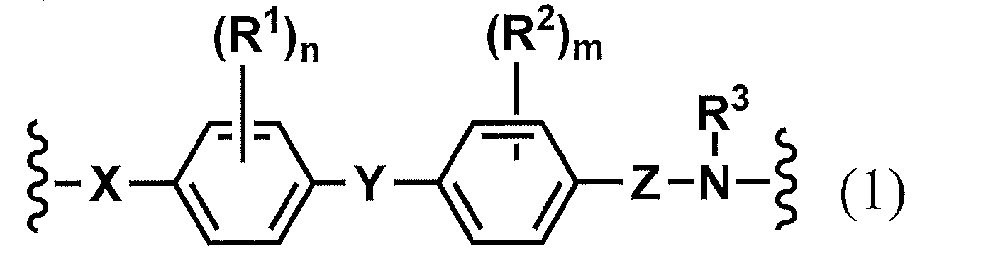
- the liquid crystal aligning agent of this invention contains the polymer (henceforth a specific polymer or a main chain polymer) obtained from the diamine component containing the diamine which has a structure represented by following formula (1). It is an alignment agent.
- a specific polymer or a main chain polymer obtained from the diamine component containing the diamine which has a structure represented by following formula (1). It is an alignment agent.
- the liquid crystal aligning agent of the present invention is a liquid crystal aligning agent containing a polymer obtained from a diamine having the structure of the following formula (1) (also referred to as a specific diamine in the present invention) and an organic solvent.
- X is a single bond or a divalent organic group
- Y and Z are each independently a divalent organic group containing alkylene
- R 1 and R 2 are each independently a monovalent group.
- An organic group, R 3 is an alkyl group having 1 to 4 carbon atoms, and m and n are each independently an integer of 0 to 4).
- Examples of the monovalent organic group herein include an alkyl group, an alkenyl group, an alkoxy group, a fluoroalkyl group, a fluoroalkenyl group, or a fluoroalkoxy group having 1 to 10 carbon atoms, preferably 1 to 3 carbon atoms.
- a monovalent organic group a methyl group is preferable.
- divalent organic group examples include benzene, naphthalene, cyclohexyl group, and groups obtained by substituting these hydrogen atoms with monovalent organic groups. Of these, benzene is preferred as the divalent organic group.
- Examples of the divalent organic group containing alkylene include an alkylene group, a group composed of an alkylene and an ether bond, a group composed of an alkylene and an ester bond, and an alkylene and an ether in which some or all of the hydrogen atoms are replaced by halogen.
- Examples include a group composed of a bond, and a group composed of an alkylene and an ester bond in which part or all of the hydrogen atoms are replaced by halogen.
- the group comprised by alkylene and alkylene and an ether bond is preferable.
- the number of carbon atoms is preferably 1 or more and 20 or less, and more preferably 1 or more and 10 or less.
- R 3 is preferably a methyl group or an ethyl group, more preferably a methyl group, from the viewpoint of ease of reaction during polymerization.
- M and n are preferably 0 in that phenyl groups are easy to overlap with each other due to less steric hindrance and re-orientate in a higher order.
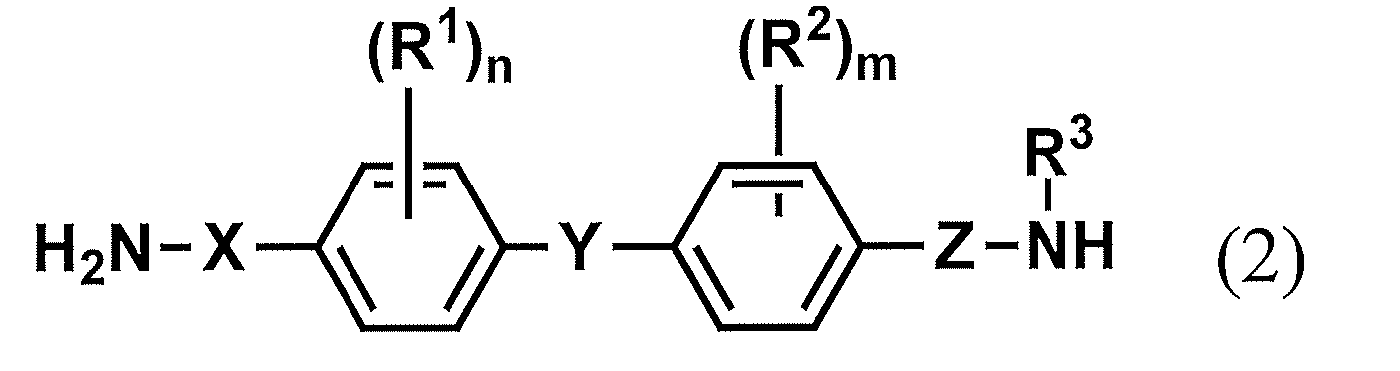
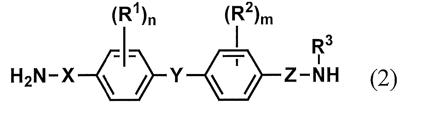
- the diamine is preferably a diamine represented by the following formula (2).
- diamine having the structure of the above formula (2) include the following, but are not limited thereto.
- the method for synthesizing the specific diamine is not particularly limited.
- the method of using the nitro compound represented by following formula (5) and converting the nitro group which it has into an amino group by a reductive reaction is mentioned.
- the catalyst used for the above reduction reaction is preferably an activated carbon-supported metal available as a commercial product, and examples thereof include palladium-activated carbon, platinum-activated carbon, and rhodium-activated carbon. Further, palladium catalyst, platinum oxide, Raney nickel, iron, zinc, tin, and the like are not necessarily activated carbon-supporting metal catalysts. In general, iron, zinc, and tin that are widely used are preferable because good results can be obtained.
- the reaction may be carried out in the presence of activated carbon.
- the amount of the activated carbon to be used is not particularly limited, but is preferably in the range of 1 to 30% by mass, more preferably 10 to 20% by mass with respect to the dinitro compound X1.
- the reaction may be carried out under pressure. In this case, in order to avoid reduction of benzene nuclei, it is carried out in a pressure range up to 20 atm. The reaction is preferably carried out in the range up to 10 atm. If necessary, an acid catalyst may be added to shorten the time.
- a solvent does not react with each raw material, it can be used without a restriction
- aprotic polar organic solvents DMF, DMSO, DMAc, NMP, etc.
- ethers Et 2 O, i-Pr 2 O, TBME, CPME, THF, dioxane, etc.
- aliphatic hydrocarbons penentane, Hexane, heptane, petroleum ether, etc.
- aromatic hydrocarbons benzene, toluene, xylene, mesitylene, chlorobenzene, dichlorobenzene, nitrobenzene, tetralin, etc.
- halogenated hydrocarbons chloroform, dichloromethane, carbon tetrachloride, dichloroethane
- Lower fatty acid esters methyl acetate, ethyl acetate, butyl acetate, methyl propionate, etc.
- nitriles acet
- solvents can be appropriately selected in consideration of the ease of reaction and the like, and can be used singly or in combination of two or more. If necessary, the solvent can be dried using a suitable dehydrating agent or desiccant and used as a non-aqueous solvent.
- the amount of the solvent used is not particularly limited, but is 0.1 to 100 times the mass of the nitro compound.
- the amount is preferably 0.5 to 30 times by mass, more preferably 1 to 10 times by mass.
- the reaction temperature is not particularly limited, but it is in the range from ⁇ 100 ° C. to the boiling point of the solvent used, preferably ⁇ 50 to 150 ° C.
- the reaction time is usually 0.05 to 350 hours, preferably 0.5 to 100 hours.
- the solvent to be used is not particularly limited as long as it does not inhibit the progress of the reaction.
- aromatic hydrocarbons such as benzene, toluene and xylene
- aliphatic hydrocarbons such as hexane and heptane.
- Cycloaliphatic alicyclic hydrocarbons such as diethyl ether, t-butyl methyl ether, ethers such as 1,2-dimethoxyethane, tetrahydrofuran and 1,4-dioxane, esters such as ethyl acetate and ethyl propionate, N , N-dimethylformamide, N, N-dimethylacetamide, N-methyl-2- Examples include amides such as pyrrolidone, amines such as triethylamine, tributylamine and N, N-dimethylaniline, pyridines such
- a base for example, an alkali metal hydroxide such as sodium hydroxide or potassium hydroxide, an alkali metal carbonate such as sodium carbonate or potassium carbonate, sodium hydrogen carbonate, or potassium hydrogen carbonate.
- Alkali metal bicarbonates such as triethylamine, tributylamine, N, N-dimethylaniline, pyridine, 4- (dimethylamino) pyridine, imidazole, 1,8-diazabicyclo [5,4,0] -7-undecene, etc.
- An organic base or the like can be used in an amount of 1 to 4 equivalents with respect to the compound represented by the general formula (7).
- the reaction temperature can be set to an arbitrary temperature from ⁇ 60 ° C. to the reflux temperature of the reaction mixture, and the reaction time varies depending on the concentration of the reaction substrate and the reaction temperature, but is usually arbitrarily within a range of 5 minutes to 100 hours. Can be set.
- the leaving group X is preferably mesylate (—OMs).
- OMs mesylate
- Other preferable leaving groups X include fluorine atom, chlorine atom, bromine atom, iodine atom, tosylate (—OTs) and the like. Can be mentioned.
- the solvent to be used is not particularly limited as long as it does not inhibit the progress of the reaction.
- aromatic hydrocarbons such as benzene, toluene and xylene
- aliphatic hydrocarbons such as hexane and heptane.
- Cycloaliphatic alicyclic hydrocarbons such as diethyl ether, t-butyl methyl ether, ethers such as 1,2-dimethoxyethane, tetrahydrofuran and 1,4-dioxane, esters such as ethyl acetate and ethyl propionate, N , N-dimethylformamide, N, N-dimethylacetamide, N-methyl-2- Examples include amides such as pyrrolidone, amines such as triethylamine, tributylamine and N, N-dimethylaniline, pyridines such
- a base for example, an alkali metal hydroxide such as sodium hydroxide or potassium hydroxide, an alkali metal carbonate such as sodium carbonate or potassium carbonate, sodium hydrogen carbonate, or potassium hydrogen carbonate.
- Alkali metal bicarbonates such as triethylamine, tributylamine, N, N-dimethylaniline, pyridine, 4- (dimethylamino) pyridine, imidazole, 1,8-diazabicyclo [5,4,0] -7-undecene, etc.
- An organic base or the like can be used at 1 to 4 equivalents relative to the compound represented by the general formula (8).
- the reaction temperature can be set to any temperature from ⁇ 60 ° C. to 25 ° C., and the reaction time varies depending on the concentration of the reaction substrate and the reaction temperature, but can usually be arbitrarily set in the range of 5 minutes to 100 hours.
- the amount of the reaction substrate may be 1 to 4 equivalents of the compound represented by the formula (10) with respect to 1 equivalent of the compound represented by the formula (9).
- the solvent to be used is not particularly limited as long as it does not inhibit the progress of the reaction.
- aromatic hydrocarbons such as benzene, toluene and xylene
- aliphatic hydrocarbons such as hexane and heptane.
- Cycloaliphatic alicyclic hydrocarbons such as diethyl ether, t-butyl methyl ether, ethers such as 1,2-dimethoxyethane, tetrahydrofuran and 1,4-dioxane, esters such as ethyl acetate and ethyl propionate, N , N-dimethylformamide, N, N-dimethylacetamide, N-methyl-2- Examples include amides such as pyrrolidone, amines such as triethylamine, tributylamine and N, N-dimethylaniline, pyridines such
- a base for example, an alkali metal hydroxide such as sodium hydroxide or potassium hydroxide, an alkali metal carbonate such as sodium carbonate or potassium carbonate, sodium hydrogen carbonate, or potassium hydrogen carbonate.
- Alkali metal bicarbonates such as triethylamine, tributylamine, N, N-dimethylaniline, pyridine, 4- (dimethylamino) pyridine, imidazole, 1,8-diazabicyclo [5,4,0] -7-undecene, etc.
- An organic base or the like can be used in an amount of 1 to 4 equivalents with respect to the compound represented by the general formula (10).
- the reaction temperature can be set to an arbitrary temperature from ⁇ 60 ° C. to the reflux temperature of the reaction mixture, and the reaction time varies depending on the concentration of the reaction substrate and the reaction temperature, but is usually arbitrarily within a range of 5 minutes to 100 hours. Can be set.
- the polymer of the present invention is a polymer obtained using the diamine.
- Specific examples include polyamic acid, polyamic acid ester, polyimide, polyurea, polyamide and the like.
- a polyimide precursor containing a structural unit represented by the following formula (3) From the viewpoint of use as a liquid crystal aligning agent, a polyimide precursor containing a structural unit represented by the following formula (3), And at least one selected from polyimides as imidized products thereof.
- X 1 is a tetravalent organic group derived from a tetracarboxylic acid derivative
- Y 1 is a divalent organic group derived from a diamine containing the structure of formula (1)
- R 11 Is a hydrogen atom or an alkyl group having 1 to 5 carbon atoms
- R 3 is an alkyl group having 1 to 4 carbon atoms.
- R 11 is preferably a hydrogen atom, a methyl group or an ethyl group from the viewpoint of ease of imidization by heating.
- R 3 is preferably a methyl group from the viewpoint of easy reaction during polymerization.
- X 1 is a tetravalent organic group derived from a tetracarboxylic acid derivative, and its structure is not particularly limited.
- X 1 in the polyimide precursor is required for the solubility of the polymer in the solvent, the coating property of the liquid crystal aligning agent, the orientation of the liquid crystal when it is used as the liquid crystal alignment film, the voltage holding ratio, the accumulated charge, etc.
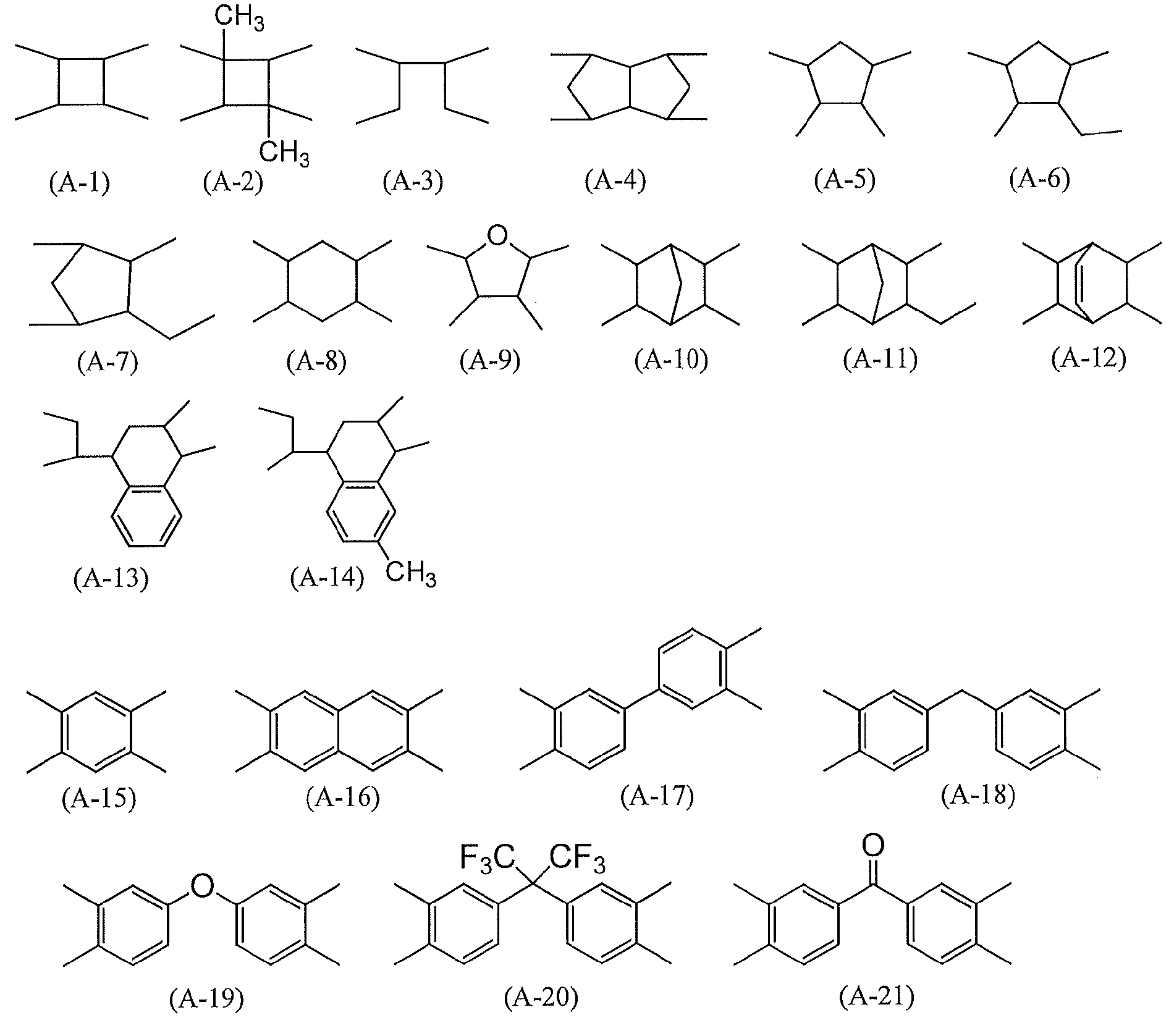
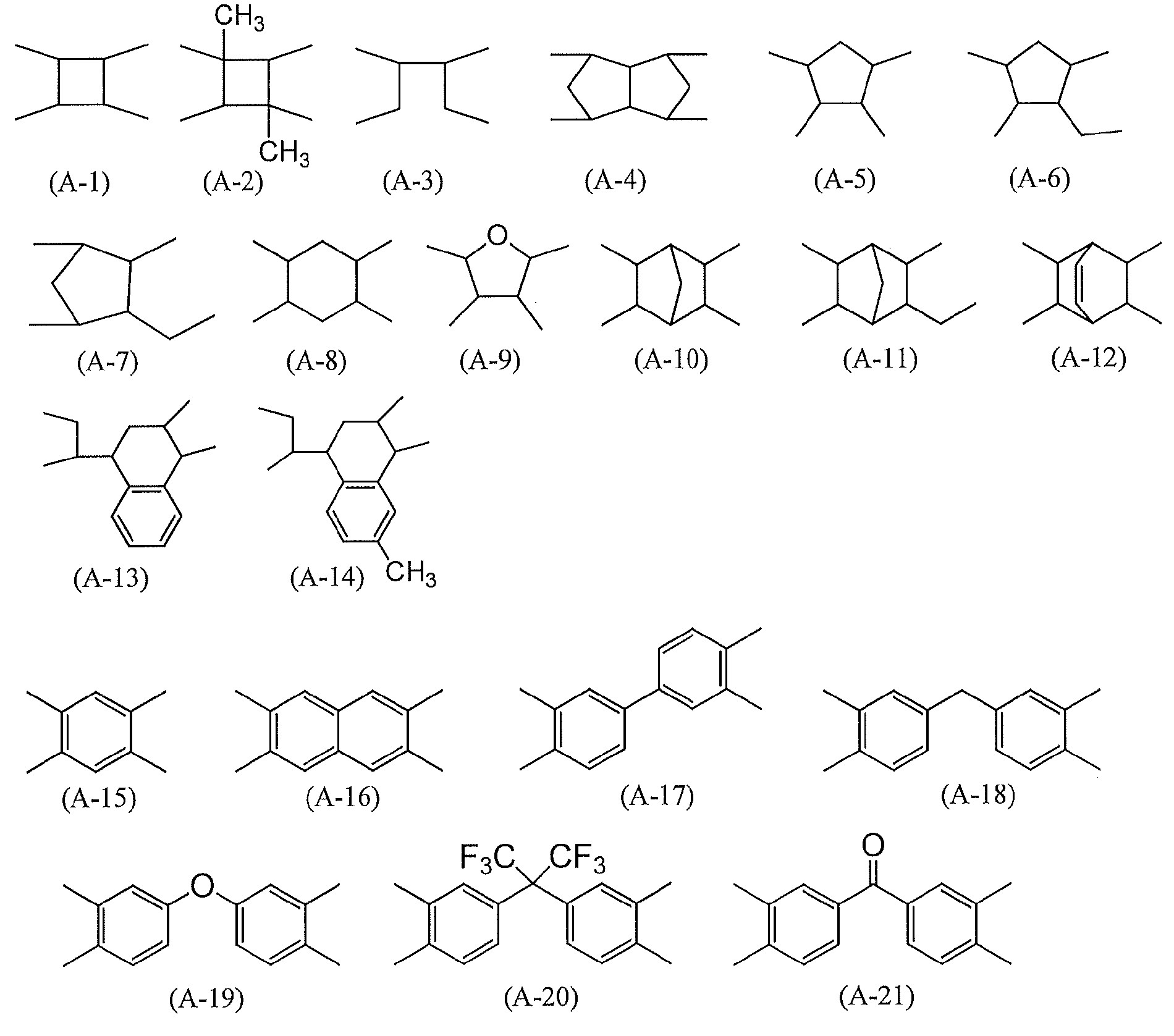
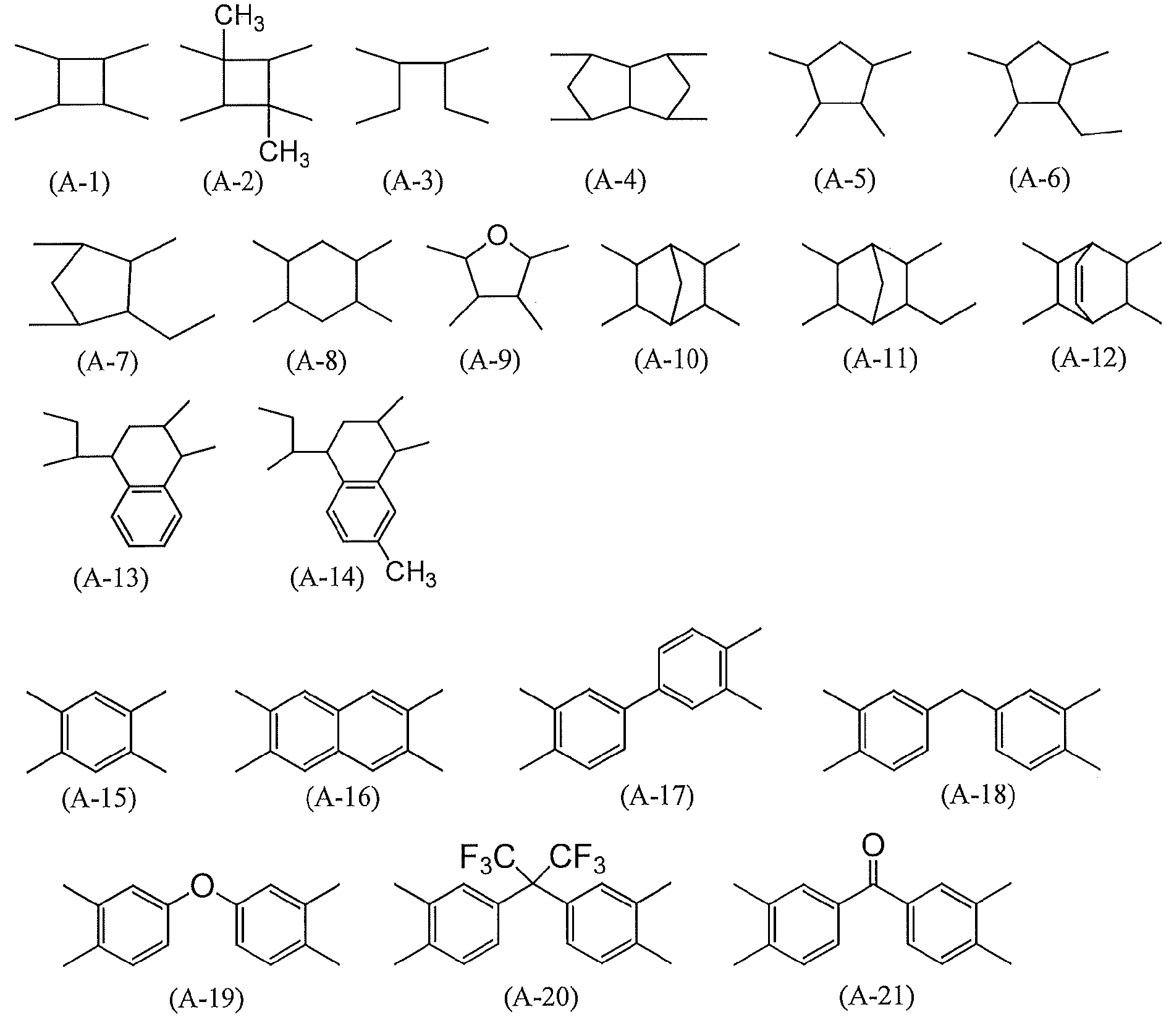
- one type may be used in the same polymer, or two or more types may be mixed. If dare Specific examples of X 1, are listed in paragraph 13 and 14, wherein the WO 2015/119168, such as the structure of formula (X-1) ⁇ (X -46) are mentioned.
- (A-1), (A-2), and (A-4) are preferable from the viewpoint of photoalignment, and (A-1) is particularly preferable.
- Y 1 includes a structure in which an amino group and an alkylamino group are removed from the diamine having the structure of Formula (1).
- Y 1 is particularly preferably a structure obtained by removing an amino group and an alkylamino group from the structure of the above formula (2).
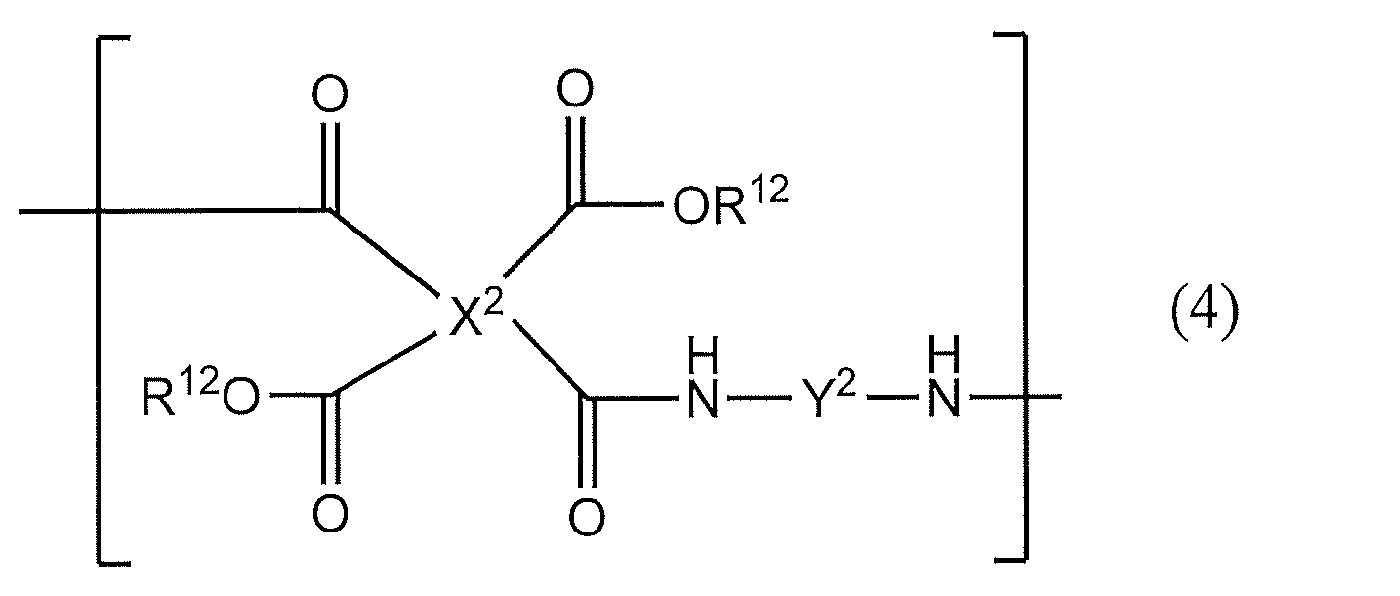
- the polyimide precursor containing the structural unit represented by the formula (3) is at least selected from the structural unit represented by the following formula (4) and a polyimide that is an imidized product thereof, as long as the effects of the present invention are not impaired.
- One kind may be included.
- X 2 is a tetravalent organic group derived from a tetracarboxylic acid derivative
- Y 2 is a divalent organic group derived from a diamine that does not include the structure of Formula (1) in the main chain direction.
- R 12 has the same definition as R 11 in formula (3).
- X 2 include the same structures as those exemplified for X 1 in formula (6), including preferred examples.
- Y 2 in the polyimide precursor is a divalent organic group derived from a diamine that does not include the structure of formula (1) in the main chain direction, and the structure is not particularly limited. Y 2 depends on the degree of required properties such as the solubility of the polymer in the solvent, the coating property of the liquid crystal aligning agent, the orientation of the liquid crystal when it is used as the liquid crystal alignment film, the voltage holding ratio, and the accumulated charge. 1 type may be selected in the same polymer, and 2 or more types may be mixed.
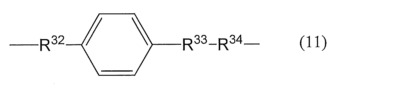
- a preferable structure of Y 2 includes a structure of the following formula (11).
- R 32 is a single bond or a divalent organic group, and a single bond is preferable.
- R 33 is a structure represented by — (CH 2 ) r —. r is an integer of 2 to 10, preferably 3 to 7. Arbitrary —CH 2 — may be replaced with an ether, ester, amide, urea, or carbamate bond under the condition that they are not adjacent to each other.
- R 34 is a single bond or a divalent organic group. Any hydrogen atom on the benzene ring may be replaced by a monovalent organic group, and a fluorine atom or a methyl group is preferred.
- the benzene ring of the specific diamine (2) is not inhibited from at least one kind of reorientation selected from the polyimide precursor containing the structural unit represented by the formula (3) and the imidized polyimide. It preferably contains a partial structure in common with the Y-benzene ring moiety.
- the liquid crystal orientation is less when the structural unit represented by the formula (3) is smaller. May improve more.
- R 21 in the formula (3) is an alkyl group, so that imidation is not caused by heating, and the alignment ability of liquid crystal molecules is lowered. Therefore, the structural unit represented by the formula (3) is preferably 1 to 70 mol%, more preferably 5 to 50 mol%, based on the sum of the formula (3) and the formula (4). Particularly preferred is 10 to 30 mol%.
- the molecular weight of the polyimide precursor used in the present invention is preferably 2,000 to 500,000 in terms of weight average molecular weight, more preferably 5,000 to 300,000, still more preferably 10,000 to 100,000. is there.
- the polyimide having a divalent group represented by the formula (1) in the main chain include a polyimide obtained by ring-closing the polyimide precursor.
- the ring closure rate (also referred to as imidation rate) of the amic acid group is not necessarily 100%, and can be arbitrarily adjusted according to the use and purpose.
- Examples of the method for imidizing the polyimide precursor include thermal imidization in which the polyimide precursor solution is heated as it is, or catalytic imidization in which a catalyst is added to the polyimide precursor solution.
- liquid crystal aligning agent of this invention contains the polymer (specific polymer) obtained from the diamine component containing the diamine which has a structure represented by Formula (1), there exists an effect as described in this invention.
- polymer specific polymer
- two or more kinds of specific polymers having different structures may be contained.
- polystyrene-phenylmaleimide poly (meta ) Acrylate and the like.
- the ratio of the specific polymer to the total polymer components is preferably 5% by mass or more, and an example thereof is 5 to 95% by mass.
- the liquid crystal aligning agent is used for producing a liquid crystal aligning film, and generally takes the form of a coating liquid from the viewpoint of forming a uniform thin film. Also in the liquid crystal aligning agent of this invention, it is preferable that it is a coating liquid containing an above-described polymer component and the organic solvent in which this polymer component is dissolved. At that time, the concentration of the polymer in the liquid crystal aligning agent can be appropriately changed by setting the thickness of the coating film to be formed. From the viewpoint of forming a uniform and defect-free coating film, the content is preferably 1% by mass or more, and from the viewpoint of storage stability of the solution, it is preferably 10% by mass or less. A particularly preferred polymer concentration is 2 to 8% by mass.
- the organic solvent contained in the liquid crystal aligning agent is not particularly limited as long as the polymer component is uniformly dissolved.
- Specific examples are N, N-dimethylformamide, N, N-dimethylacetamide, N-methyl-2-pyrrolidone, N-ethyl-2-pyrrolidone, dimethyl sulfoxide, ⁇ -butyrolactone, 1,3-dimethyl.
- -Imidazolidinone methyl ethyl ketone, cyclohexanone, cyclopentanone and the like.
- N-methyl-2-pyrrolidone, N-ethyl-2-pyrrolidone, or ⁇ -butyrolactone is preferably used.
- the organic solvent contained in the liquid crystal aligning agent uses a mixed solvent that is used in combination with a solvent that improves the coating properties and the surface smoothness of the coating film when the liquid crystal aligning agent is applied in addition to the above-described solvents.
- a mixed solvent is also preferably used in the liquid crystal aligning agent of the present invention. Specific examples of the organic solvent to be used in combination are given below, but the organic solvent is not limited to these examples.
- ethanol isopropyl alcohol, 1-butanol, 2-butanol, isobutyl alcohol, tert-butyl alcohol, 1-pentanol, 2-pentanol, 3-pentanol, 2-methyl-1-butanol, isopentyl alcohol, tert-pentyl alcohol, 3-methyl-2-butanol, neopentyl alcohol, 1-hexanol, 2-methyl-1-pentanol, 2-methyl-2-pentanol, 2-ethyl-1-butanol, 1-heptanol 2-heptanol, 3-heptanol, 1-octanol, 2-octanol, 2-ethyl-1-hexanol, cyclohexanol, 1-methylcyclohexanol, 2-methylcyclohexanol, 3-methylcyclohexanol, 1,2- Ethane All, 1,2-propanediol, 1,3-propan
- D 1 represents an alkyl group having 1 to 3 carbon atoms
- D 2 represents an alkyl group having 1 to 3 carbon atoms
- D-3 represents an alkyl group having 1 to 4 carbon atoms.
- the kind and content of such a solvent are appropriately selected according to the application device, application conditions, application environment, and the like of the liquid crystal aligning agent.
- the liquid crystal aligning agent of the present invention may additionally contain components other than the polymer component and the organic solvent as long as the effects of the present invention are not impaired.
- additional components include an adhesion aid for increasing the adhesion between the liquid crystal alignment film and the substrate and the adhesion between the liquid crystal alignment film and the sealing material, a crosslinking agent for increasing the strength of the liquid crystal alignment film, and the liquid crystal alignment.
- examples thereof include dielectrics and conductive materials for adjusting the dielectric constant and electric resistance of the film. Specific examples of these additional components are as disclosed in various known literatures relating to liquid crystal aligning agents. If an example is given, pages 53 [0105] to 55 of the pamphlet of Japanese Unexamined Patent Publication No. 2015/060357. And the like as disclosed in [0116].
- the method for producing a substrate having the liquid crystal alignment film of the present invention is as follows. [I] (A) A polymer obtained from a diamine component containing a diamine having a structure represented by the formula (1), and (B) a polymer composition containing an organic solvent is converted into a conductive film for driving a lateral electric field.
- a lateral electric field drive type liquid crystal display element can be obtained.
- the second substrate instead of using a substrate having no lateral electric field driving conductive film instead of a substrate having a lateral electric field driving conductive film, the above steps [I] to [III] (for lateral electric field driving) Since a substrate having no conductive film is used, for the sake of convenience, in this application, the steps [I ′] to [III ′] may be abbreviated as steps), thereby providing a first liquid crystal alignment film having alignment controllability. Two substrates can be obtained.
- the manufacturing method of the horizontal electric field drive type liquid crystal display element is: [IV] A step of obtaining a liquid crystal display element by arranging the first and second substrates obtained above so that the liquid crystal alignment films of the first and second substrates face each other with liquid crystal interposed therebetween; Have Thereby, a horizontal electric field drive type liquid crystal display element can be obtained.
- step [I] a polymer composition containing a photosensitive main polymer and an organic solvent is applied to a substrate having a conductive film for driving a lateral electric field to form a coating film.
- ⁇ Board> Although it does not specifically limit about a board
- the substrate has a conductive film for driving a lateral electric field.
- the conductive film include, but are not limited to, ITO (Indium Tin Oxide) and IZO (Indium Zinc Oxide) when the liquid crystal display element is a transmission type.
- examples of the conductive film include a material that reflects light such as aluminum, but are not limited thereto.
- a method for forming a conductive film on a substrate a conventionally known method can be used.
- the method for applying the polymer composition described above onto a substrate having a conductive film for driving a lateral electric field is not particularly limited.
- the application method is generally performed by screen printing, offset printing, flexographic printing, an inkjet method, or the like.
- Other coating methods include a dipping method, a roll coater method, a slit coater method, a spinner method (rotary coating method), or a spray method, and these may be used depending on the purpose.
- the polymer composition After the polymer composition is applied on a substrate having a conductive film for driving a transverse electric field, it is heated to 50 to 300 ° C., preferably 50 to 300 ° C. by a heating means such as a hot plate, a thermal circulation oven or an IR (infrared) oven.
- the film can be obtained by evaporating the solvent at 180 ° C.
- the drying temperature at this time is preferably lower than that in the step [III] from the viewpoint of liquid crystal alignment stability. If the thickness of the coating film is too thick, it will be disadvantageous in terms of power consumption of the liquid crystal display element, and if it is too thin, the reliability of the liquid crystal display element may be lowered.
- it is preferably 5 nm to 300 nm, more preferably 10 nm to 150 nm. It is. In addition, it is also possible to provide the process of cooling the board
- step [II] the coating film obtained in step [I] is irradiated with polarized ultraviolet rays.
- the substrate is irradiated with polarized ultraviolet rays through a polarizing plate from a certain direction.
- ultraviolet rays to be used ultraviolet rays having a wavelength in the range of 100 nm to 400 nm can be used.
- the optimum wavelength is selected through a filter or the like depending on the type of coating film to be used.
- ultraviolet light having a wavelength in the range of 240 nm to 400 nm can be selected and used so that a photodegradation reaction can be selectively induced.
- the ultraviolet light for example, light emitted from a high-pressure mercury lamp or a metal halide lamp can be used.
- the irradiation amount of polarized ultraviolet rays depends on the coating film used.
- the amount of irradiation is polarized ultraviolet light that realizes the maximum value of ⁇ A (hereinafter also referred to as ⁇ Amax), which is the difference between the ultraviolet light absorbance in a direction parallel to the polarization direction of polarized ultraviolet light and the ultraviolet light absorbance in a direction perpendicular to the polarization direction of the polarized ultraviolet light.
- the amount is preferably in the range of 1% to 70%, more preferably in the range of 1% to 50%.
- step [III] the ultraviolet-irradiated coating film polarized in step [II] is heated.
- An orientation control ability can be imparted to the coating film by heating.
- a heating means such as a hot plate, a heat circulation type oven, or an IR (infrared) type oven can be used.
- the heating temperature can be determined in consideration of the temperature at which good liquid crystal alignment stability and electrical characteristics are exhibited in the coating film used.
- the heating temperature is preferably within a temperature range in which the main chain polymer exhibits good liquid crystal alignment stability. If the heating temperature is too low, the anisotropy effect due to heat and thermal imidization tend to be insufficient, and if the heating temperature is too high, the anisotropy imparted by polarized light exposure In this case, it may be difficult to reorient in one direction due to self-organization.
- the thickness of the coating film formed after heating is preferably 5 nm to 300 nm, more preferably 50 nm to 150 nm, for the same reason described in the step [I].
- the production method of the present invention can realize highly efficient introduction of anisotropy into the coating film. And a board
- the step [IV] is performed in the same manner as in the above [I ′] to [III ′], similarly to the substrate (first substrate) obtained in [III] and having the liquid crystal alignment film on the conductive film for lateral electric field driving.
- the obtained liquid crystal alignment film-attached substrate (second substrate) having no conductive film is placed oppositely so that both liquid crystal alignment films face each other through liquid crystal, and a liquid crystal cell is formed by a known method.
- This is a step of manufacturing a lateral electric field drive type liquid crystal display element.
- a substrate having no lateral electric field driving conductive film was used in place of the substrate having the lateral electric field driving conductive film in the step [I].
- steps [I] to [III] It can be carried out in the same manner as in steps [I] to [III]. Since the difference between the steps [I] to [III] and the steps [I ′] to [III ′] is only the presence or absence of the conductive film, the description of the steps [I ′] to [III ′] is omitted. To do.
- the first and second substrates described above are prepared, spacers are dispersed on the liquid crystal alignment film of one substrate, and the liquid crystal alignment film surface is on the inside.
- the other substrate is bonded and the liquid crystal is injected under reduced pressure, or the liquid crystal is dropped on the liquid crystal alignment film surface on which the spacers are dispersed, and then the substrate is bonded and sealed.
- Etc. can be illustrated.
- the diameter of the spacer at this time is preferably 1 ⁇ m to 30 ⁇ m, more preferably 2 ⁇ m to 10 ⁇ m. This spacer diameter determines the distance between the pair of substrates that sandwich the liquid crystal layer, that is, the thickness of the liquid crystal layer.
- substrate with a coating film of this invention irradiates the polarized ultraviolet-ray, after apply
- high-efficiency anisotropy is introduced into the main chain polymer film, and a substrate with a liquid crystal alignment film having a liquid crystal alignment control ability is manufactured.
- the coating film used in the present invention the introduction of highly efficient anisotropy into the coating film is realized by utilizing the principle of molecular reorientation induced by self-assembly based on the photoreaction of the main chain.
- the main chain type polymer has a photodegradable group as a photoreactive group
- a liquid crystal display element is formed.
- the coating film used in the method of the present invention is a liquid crystal alignment film having anisotropy introduced with high efficiency and excellent alignment control ability by sequentially performing irradiation of polarized ultraviolet rays on the coating film and heat treatment. can do.
- the irradiation amount of polarized ultraviolet rays to the coating film and the heating temperature in the heat treatment are optimized. Thereby, introduction of anisotropy into the coating film with high efficiency can be realized.
- the optimal irradiation amount of polarized ultraviolet light for introducing highly efficient anisotropy into the coating film used in the present invention is the irradiation amount of polarized ultraviolet light that optimizes the amount of photodegradation reaction of the photosensitive group in the coating film.
- the amount of photoreaction is not sufficient. In that case, sufficient self-organization does not proceed even after heating.
- the optimum amount of the photolytic reaction of the photosensitive group by irradiation with polarized ultraviolet light is preferably 0.1 to 90 mol% of the polymer film. More preferably, it is 1 mol% to 80 mol%.
- the amount of photodecomposition reaction of the photosensitive group in the main chain of the polymer film is optimized by optimizing the irradiation amount of polarized ultraviolet rays. Then, in combination with the subsequent heat treatment, highly efficient introduction of anisotropy into the coating film used in the present invention is realized. In that case, a suitable amount of polarized ultraviolet rays can be determined based on the evaluation of ultraviolet absorption of the coating film used in the present invention.
- the ultraviolet absorption in the direction parallel to the polarization direction of the polarized ultraviolet ray and the ultraviolet absorption in the vertical direction after the irradiation with the polarized ultraviolet ray are measured.
- ⁇ A which is the difference between the ultraviolet absorbance in the direction parallel to the polarization direction of polarized ultraviolet rays and the ultraviolet absorbance in the direction perpendicular to the polarization direction of the polarized ultraviolet rays.
- the maximum value of ⁇ A ( ⁇ Amax) realized in the coating film used in the present invention and the irradiation amount of polarized ultraviolet light that realizes it are obtained.
- a preferable amount of polarized ultraviolet rays to be irradiated in the production of the liquid crystal alignment film can be determined on the basis of the amount of polarized ultraviolet rays to realize this ⁇ Amax.
- the above-described main chain type polymer provides liquid crystal alignment stability as a reference, as described above.
- a suitable heating temperature should be determined. Therefore, for example, the temperature range in which the main chain polymer used in the present invention provides liquid crystal alignment stability is determined in consideration of the temperature at which good liquid crystal alignment stability and electrical characteristics are exhibited in the coating film used. And can be set in a temperature range according to a liquid crystal alignment film made of a conventional polyimide or the like. That is, the heating temperature after irradiation with polarized ultraviolet rays is preferably 100 ° C. to 300 ° C., more preferably 150 ° C. to 250 ° C. By doing so, greater anisotropy is imparted to the coating film used in the present invention.
- the liquid crystal display element provided by the present invention exhibits high reliability against external stresses such as light and heat.
- the lateral electric field drive type liquid crystal display element substrate manufactured using the polymer of the present invention or the lateral electric field drive type liquid crystal display element having the substrate has excellent reliability and a large screen. And can be suitably used for high-definition liquid crystal televisions.
- the liquid crystal alignment film manufactured by the method of the present invention has excellent liquid crystal alignment stability and reliability, it can be used for a variable phase shifter using liquid crystal. For example, it can be suitably used for an antenna that can vary the resonance frequency.
- DA-1 compound represented by the following structural formula (DA-1)
- DA-2 structural formula (DA- Compound DA-3 represented by 2): Compound CA-1 represented by the following structural formula (DA-3): Compound represented by the following structural formula (CA-1)
- FT-NMR Fourier transform type superconducting nuclear magnetic resonance apparatus
- INOVA-400 manufactured by Varian 400 MHz.
- Solvent deuterated N, N-dimethyl sulfoxide (DMSO-d 6 ).
- Standard substance Tetramethylsilane (TMS).
- the viscosity of the polymer solution was measured using an E-type viscometer TVE-22H (manufactured by Toki Sangyo Co., Ltd.), a sample amount of 1.1 mL, cone rotor TE-1 (1 ° 34 ′, R24), temperature 25 Measured at ° C.
- DA-1 is a novel compound that has not been published yet, and its synthesis method will be described in detail in Synthesis Example 1 below.
- Second step Synthesis of 4- (2- (4-nitrophenoxy) ethoxy) phenethyl methanesulfonate (DA-1-2)
- N-methyl-2- (4- (2- (4-nitrophenoxy) ethoxy) phenyl) ethanamine (10.0 g, 31.6 mmol) was dissolved in tetrahydrofuran (100.0 g), and 5% palladium-carbon (0 0.5 g) and stirred at 50 ° C. for 5 hours under a hydrogen atmosphere.
- the disappearance of the raw materials was confirmed by HPLC, dissolved in tetrahydrofuran (50.0 g), the catalyst was removed by filtration, and the filtrate was concentrated. This was washed with heptane (50.0 g), and the precipitated solid was filtered and dried under reduced pressure at 50 ° C. to obtain DA-1 (white powder, yield: 9.0 g, yield: 98%).
- a method for manufacturing a liquid crystal cell for evaluating the liquid crystal alignment will be described below.
- a liquid crystal cell having a configuration of an FFS liquid crystal display element was manufactured.
- a substrate with electrodes was prepared.
- the substrate is a glass substrate having a size of 30 mm ⁇ 35 mm and a thickness of 0.7 mm.
- an IZO electrode constituting the counter electrode as the first layer was formed on the entire surface.
- a SiN (silicon nitride) film formed by the CVD method was formed as the second layer.
- the second layer SiN film has a thickness of 500 nm and functions as an interlayer insulating film.
- a comb-like pixel electrode formed by patterning an IZO film is arranged as a third layer, and two pixels, a first pixel and a second pixel, are formed. .
- the size of each pixel is 10 mm long and about 5 mm wide.
- the first-layer counter electrode and the third-layer pixel electrode are electrically insulated by the action of the second-layer SiN film.
- the pixel electrode of the third layer is a comb tooth formed by arranging a plurality of U-shaped electrode elements whose central portion is bent, as in the figure described in Japanese Patent Application Laid-Open No. 2014-77845 (Japan Published Patent Publication). It has a shape. The width in the short direction of each electrode element is 3 ⁇ m, and the distance between the electrode elements is 6 ⁇ m. Since the pixel electrode forming each pixel is configured by arranging a plurality of bent-shaped electrode elements having a bent central portion, the shape of each pixel is not rectangular but bent at the central portion in the same manner as the electrode elements. It has a shape that is similar to a bold, Kumon character. Each pixel is divided into upper and lower portions with a central bent portion as a boundary, and has a first region on the upper side of the bent portion and a second region on the lower side.
- the formation directions of the electrode elements of the pixel electrodes constituting them are different. That is, when the direction of a line segment projected onto the substrate with the polarization plane of polarized ultraviolet rays to be described later is used as a reference, in the first region of the pixel, the electrode element of the pixel electrode forms an angle of + 10 ° (clockwise). In the second region of the pixel, the electrode element of the pixel electrode is formed at an angle of ⁇ 10 ° (clockwise).
- the direction of the rotation operation (in-plane switching) of the liquid crystal induced by the voltage application between the pixel electrode and the counter electrode in the substrate plane is It comprised so that it might become a mutually reverse direction.
- the liquid crystal aligning agent obtained in the synthesis example and the comparative synthesis example was filtered through a 1.0 ⁇ m filter, and then applied to the prepared substrate with electrodes by spin coating. Subsequently, it was dried for 90 seconds on a hot plate set to 70 ° C. Next, using an exposure apparatus manufactured by Ushio Electric Co., Ltd .: APL-L050121S1S-APW01, the substrate was irradiated with linearly polarized ultraviolet light from a vertical direction through a wavelength selection filter and a polarizing plate.
- the direction of the polarization plane was set so that the direction of the line segment obtained by projecting the polarization plane of polarized ultraviolet rays onto the substrate was inclined by 10 ° with respect to the third-layer IZO comb-teeth electrode. Subsequently, baking was performed for 30 minutes in an IR (infrared) oven set at 230 ° C., and a substrate with a polyimide liquid crystal alignment film having a film thickness of 100 nm subjected to alignment treatment was obtained.
- IR infrared
- substrate with a polyimide liquid crystal aligning film by which the alignment process was performed similarly to the above was also obtained for the glass substrate which has the columnar spacer of 4 micrometers in height with the ITO electrode formed in the back surface as a counter substrate.
- a set of these two substrates with a liquid crystal alignment film is used as one set, and a sealing agent is printed on the other substrate leaving a liquid crystal injection port.
- the polarizing planes were bonded and pressure-bonded so that the line segments projected onto the substrate were parallel. Thereafter, the sealing agent was cured to produce an empty cell having a cell gap of 4 ⁇ m.
- Liquid crystal MLC-7026-100 (negative liquid crystal manufactured by Merck & Co., Inc.) was injected into the empty cell by a reduced pressure injection method, and the injection port was sealed to obtain an FFS liquid crystal cell. Thereafter, the obtained liquid crystal cell was heated at 120 ° C. for 30 minutes and allowed to stand at 23 ° C. overnight, and then used for evaluation of liquid crystal alignment.
- the rotation angle when the liquid crystal cell was rotated from the angle at which the second region of the first pixel became darkest to the angle at which the first region became darkest was calculated as an angle ⁇ .
- the second area was compared with the first area, and a similar angle ⁇ was calculated.
- the average value of the angle ⁇ values of the first pixel and the second pixel was calculated as the angle ⁇ of the liquid crystal cell.
- the voltage holding ratio was evaluated. Specifically, an alternating voltage of 2 VPP is applied to the liquid crystal cell obtained by the above method at a temperature of 70 ° C. for 60 ⁇ s, and the voltage after 1 second is measured to determine how much the voltage can be maintained. Calculated as retention (also referred to as VHR). The measurement was performed using a voltage holding ratio measuring device (VHR-1, manufactured by Toyo Technica Co., Ltd.) with settings of Voltage: ⁇ 1 V, Pulse Width: 60 ⁇ s, and Frame Period: 1000 ms. When the value of the voltage holding ratio of the liquid crystal cell was 80% or more, it was defined as “good”, and when the value of the voltage holding ratio was less than 80%, it was defined as “bad”.
- VHR-1 voltage holding ratio measuring device
- Example 1 Using the liquid crystal aligning agent (A-1) obtained in Synthesis Example 2, two types of liquid crystal cells were produced as described above. Irradiation with polarized ultraviolet rays was performed using a high pressure mercury lamp through a wavelength selection filter: 240LCF and a 254 nm type polarizing plate. The irradiation amount of polarized ultraviolet rays is measured by measuring the amount of light using an illuminometer UVD-S254SB manufactured by Ushio Electric Co., Ltd., and changing the wavelength in the range of 600 to 1800 mJ / cm 2. Three or more liquid crystal cells having different amounts were prepared.
- the polarized UV irradiation amount with the best angle ⁇ was 1800 mJ / cm 2 , and the angle ⁇ was 0.15 °, which was good.
- the voltage holding ratio was 92.4%, which was favorable.
- Table 1 shows the results of evaluation of polarized UV irradiation amount, liquid crystal orientation evaluation, and evaluation of voltage holding ratio when the angle ⁇ was the best when using the liquid crystal aligning agents obtained in the synthesis examples and comparative synthesis examples. Indicates.
- Example 1 As shown in Table 1, in Example 1, the angle ⁇ , which is the difference between the orientation azimuth angles before and after AC driving, is good when it is less than 0.3 °, and at the same time, the voltage holding ratio is good as 80% or more. Since both have good afterimage characteristics, the display quality of the liquid crystal display element is excellent. On the other hand, in Comparative Examples 1 and 2, the characteristics satisfying both the angle ⁇ and the voltage holding ratio were not confirmed. As described above, it was confirmed that the liquid crystal display device manufactured by the method of the present invention exhibits very excellent afterimage characteristics.
- a substrate for a horizontal electric field drive type liquid crystal display element manufactured using the composition of the present invention or a horizontal electric field drive type liquid crystal display element having the substrate has excellent reliability, and has a large screen and a high definition liquid crystal television. It can utilize suitably for.
- the liquid crystal alignment film manufactured by the method of the present invention has excellent liquid crystal alignment stability and reliability, it can be used for a variable phase shifter using liquid crystal. For example, it can be suitably used for an antenna that can vary the resonance frequency.
Landscapes
- Chemical & Material Sciences (AREA)
- Organic Chemistry (AREA)
- Physics & Mathematics (AREA)
- Nonlinear Science (AREA)
- Crystallography & Structural Chemistry (AREA)
- Chemical Kinetics & Catalysis (AREA)
- Medicinal Chemistry (AREA)
- Polymers & Plastics (AREA)
- Health & Medical Sciences (AREA)
- Optics & Photonics (AREA)
- General Physics & Mathematics (AREA)
- Mathematical Physics (AREA)
- Spectroscopy & Molecular Physics (AREA)
- Materials Engineering (AREA)
- Engineering & Computer Science (AREA)
- Liquid Crystal (AREA)
- Macromolecular Compounds Obtained By Forming Nitrogen-Containing Linkages In General (AREA)
- Compositions Of Macromolecular Compounds (AREA)
- Organic Low-Molecular-Weight Compounds And Preparation Thereof (AREA)
Abstract
Description


[II] [I]で得られた塗膜に偏光した紫外線を照射する工程;及び
[III] [II]で得られた塗膜を加熱する工程;
を有することによって配向制御能が付与された横電界駆動型液晶表示素子用液晶配向膜を得る、前記液晶配向膜を有する基板の製造方法。
[I’] 第2の基板上に請求項1乃至7記載の組成物を、塗布して塗膜を形成する工程;
[II’] [I’]で得られた塗膜に偏光した紫外線を照射する工程;
[III’] [II’]で得られた塗膜を加熱する工程;を有することによって配向制御能が付与された液晶配向膜を得る、前記液晶配向膜を有する第2の基板を得る工程;及び
[IV] 液晶を介して前記第1及び第2の基板の液晶配向膜が相対するように、前記第1及び第2の基板を対向配置して液晶表示素子を得る工程;を有することにより、横電界駆動型液晶表示素子を得る、該液晶表示素子の製造方法。


本発明の液晶配向剤は、下記式(1)で表される構造を有するジアミンを含むジアミン成分から得られる重合体(以下、特定重合体とも、主鎖型高分子とも言う)を含有する液晶配向剤である。以下、各条件につき詳述する。
本発明の液晶配向剤は、下記式(1)の構造を有するジアミン(本発明では、特定ジアミンともいう。)から得られる重合体と、有機溶媒とを含有する液晶配向剤である。



上記特定ジアミンを合成する方法は特に限定されない。例えば、下記式(5)で表されるニトロ化合物を使用し、その有するニトロ基を還元反応によりアミノ基に変換する方法が挙げられる。

反応温度は特に限定されないが、-100℃から使用する溶媒の沸点までの範囲、好ましくは、-50~150℃である。反応時間は、通常0.05~350時間、好ましくは0.5~100時間である。
式(5)の化合物を合成する方法に特に制限はないが、例えば、下記式(7)で表される脱離基Xを有するニトロベンゼン誘導体を、市販のメチルアミン溶液と反応させて合成する方法が挙げられる。好ましい脱離基Xとしてはフッ素原子、塩素原子、臭素原子、ヨウ素原子、トシラート(-OTs)、メシラート(-OMs)などが挙げられる。

式(7)の化合物を合成する方法に特に制限はないが、例えば、下記式(8)で表されるヒドロキシ基を有するニトロベンゼン誘導体を、市販のメシルクロライドと反応させて合成する方法が挙げられる。合成のし易さの観点から脱離基Xはメシラート(-OMs)が好ましいが、この他に好ましい脱離基Xとしてフッ素原子、塩素原子、臭素原子、ヨウ素原子、トシラート(-OTs)などが挙げられる。

式(8)の化合物を合成する方法に特に制限はないが、例えば、市販のフェノール誘導体(9)と下記式(10)で表される脱離基を有するニトロベンゼン誘導体を反応させて合成する方法が挙げられる。好ましい脱離基Xとしてフッ素原子、塩素原子、臭素原子、ヨウ素原子、トシラート(-OTs)、メシラート(-OMs)などが挙げられる。

本発明の重合体は、上記ジアミンを用いて得られる重合体である。具体例としては、ポリアミック酸、ポリアミック酸エステル、ポリイミド、ポリウレア、ポリアミドなどが挙げられるが、液晶配向剤としての使用の観点から、下記式(3)で表される構造単位を含むポリイミド前駆体、及びそのイミド化物であるポリイミドから選ばれる少なくとも1種であるとより好ましい。

X1はテトラカルボン酸誘導体に由来する4価の有機基であり、その構造は特に限定されるものではない。また、ポリイミド前駆体中のX1は、重合体の溶媒への溶解性や液晶配向剤の塗布性、液晶配向膜とした場合における液晶の配向性、電圧保持率、蓄積電荷など、必要とされる特性の程度に応じて適宜選択され、同一重合体中に1種類であってもよく、2種類以上が混在していても良い。
X1の具体例をあえて示すならば、国際公開公報2015/119168の13項~14項に掲載される、式(X-1)~(X-46)の構造などが挙げられる。
式(3)において、Y1の具体例としては前記式(1)の構造を有するジアミンからアミノ基とアルキルアミノ基を除いた構造を挙げることができる。なかでも、Y1は上記式(2)の構造からアミノ基とアルキルアミノ基を除いた構造であるのが特に好ましい。
式(3)で表される構造単位を含むポリイミド前駆体は、本発明の効果を損なわない範囲において、下記式(4)で表される構造単位、及びそのイミド化物であるポリイミドから選ばれる少なくとも1種を含んでいても良い。
R33は-(CH2)r-で表される構造である。rは2~10の整数であり、3~7が好ましい。また、任意の-CH2-はそれぞれ隣り合わない条件でエーテル、エステル、アミド、ウレア、カルバメート結合に置き換えられても良い。
R34は単結合又は2価の有機基である。
ベンゼン環上の任意の水素原子は1価の有機基で置き換えられても良く、フッ素原子又はメチル基が好ましい。
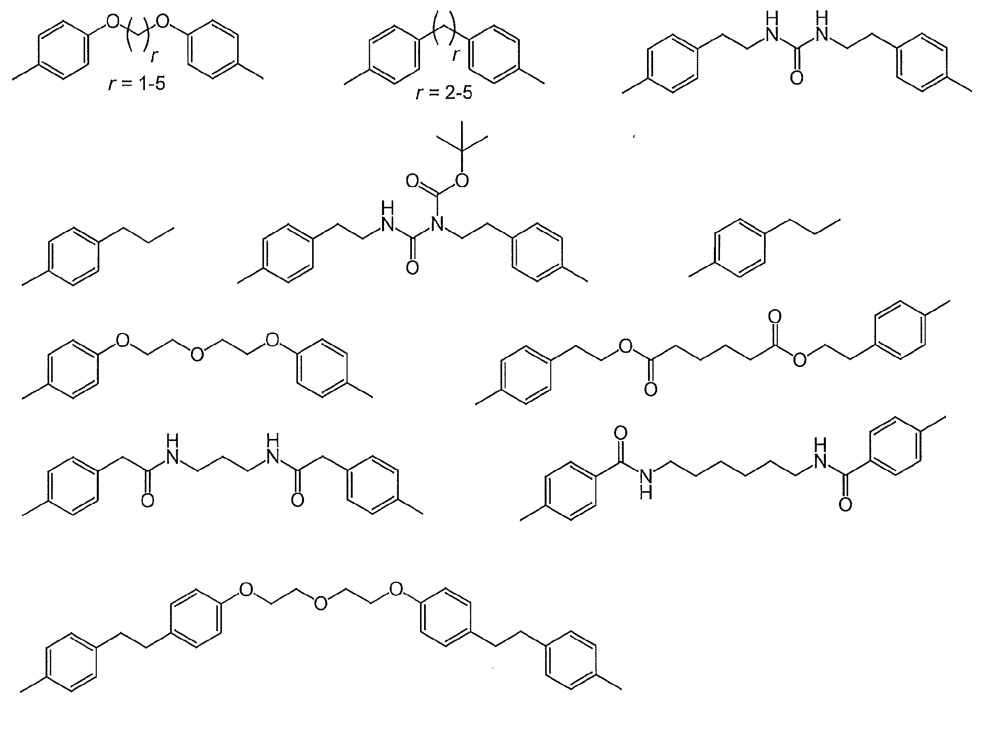

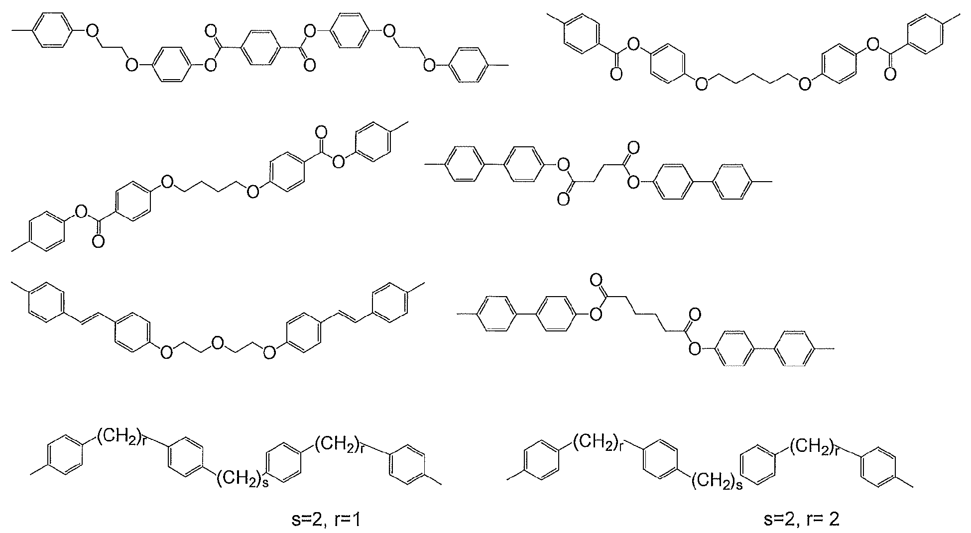

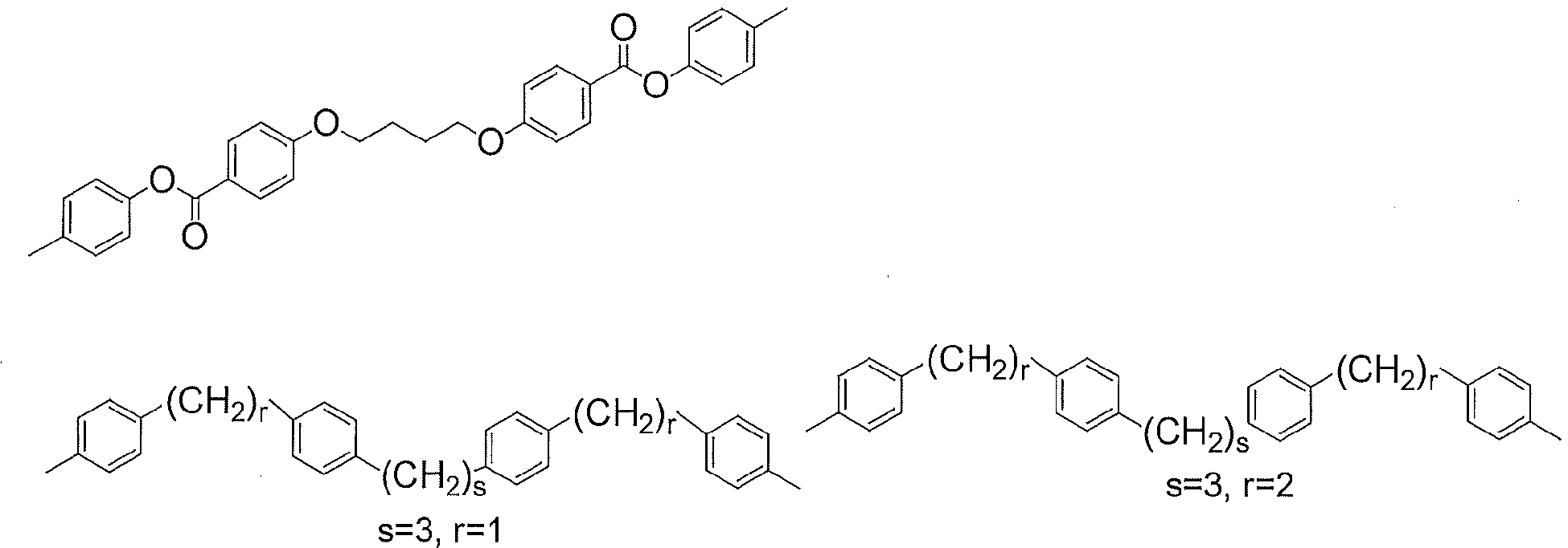
式(1)で表される2価の基を主鎖に有するポリイミドとしては、前記のポリイミド前駆体を閉環させて得られるポリイミドが挙げられる。このポリイミドにおいては、アミド酸基の閉環率(イミド化率ともいう)は必ずしも100%である必要はなく、用途や目的に応じて任意に調整できる。
ポリイミド前駆体をイミド化させる方法としては、ポリイミド前駆体の溶液をそのまま加熱する熱イミド化、又はポリイミド前駆体の溶液に触媒を添加する触媒イミド化が挙げられる。
本発明の液晶配向剤は、式(1)で表される構造を有するジアミンを含むジアミン成分から得られる重合体(特定重合体)を含有するものであるが、本発明に記載の効果を奏する限度において、異なる構造の特定重合体を2種以上含有していてもよい。また、特定重合体に加えて、その他の重合体、即ち式(1)で表される2価の基を有さない重合体を含有していてもよい。その他の重合体の種類としては、ポリアミック酸、ポリイミド、ポリアミック酸エステル、ポリエステル、ポリアミド、ポリウレア、ポリオルガノシロキサン、セルロース誘導体、ポリアセタール、ポリスチレンまたはその誘導体、ポリ(スチレン-フェニルマレイミド)誘導体、ポリ(メタ)アクリレートなどを挙げることができる。本発明の液晶配向剤がその他の重合体を含有する場合、全重合体成分に対する特定重合体の割合は5質量%以上であることが好ましく、その一例として5~95質量%が挙げられる。

本発明の液晶配向膜を有する基板の製造方法は、
[I] (A)式(1)で表される構造を有するジアミンを含むジアミン成分から得られる重合体、及び(B)有機溶媒を含有する重合体組成物を、横電界駆動用の導電膜を有する基板上に塗布して塗膜を形成する工程;
[II] [I]で得られた塗膜に偏光した紫外線を照射する工程;及び
[III] [II]で得られた塗膜を加熱する工程;
を有する。
上記工程により、配向制御能が付与された横電界駆動型液晶表示素子用液晶配向膜を得ることができ、該液晶配向膜を有する基板を得ることができる。
第2の基板は、横電界駆動用の導電膜を有する基板に代わって、横電界駆動用の導電膜を有しない基板を用いる以外、上記工程[I]~[III](横電界駆動用の導電膜を有しない基板を用いるため、便宜上、本願において、工程[I’]~[III’]と略記する場合がある)を用いることにより、配向制御能が付与された液晶配向膜を有する第2の基板を得ることができる。
[IV] 上記で得られた第1及び第2の基板を、液晶を介して第1及び第2の基板の液晶配向膜が相対するように、対向配置して液晶表示素子を得る工程;
を有する。これにより横電界駆動型液晶表示素子を得ることができる。
<工程[I]>
工程[I]では、横電界駆動用の導電膜を有する基板上に、感光性の主型高分子及び有機溶媒を含有する重合体組成物を塗布して塗膜を形成する。
基板については、特に限定はされないが、製造される液晶表示素子が透過型である場合、透明性の高い基板が用いられることが好ましい。その場合、特に限定はされず、ガラス基板、またはアクリル基板やポリカーボネート基板等のプラスチック基板等を用いることができる。
また、反射型の液晶表示素子への適用を考慮し、シリコンウェハなどの不透明な基板も使用できる。
基板は、横電界駆動用の導電膜を有する。
該導電膜として、液晶表示素子が透過型である場合、ITO(Indium Tin Oxide:酸化インジウムスズ)、IZO(Indium Zinc Oxide:酸化インジウム亜鉛)などを挙げることができるが、これらに限定されない。
また、反射型の液晶表示素子の場合、導電膜として、アルミなどの光を反射する材料などを挙げることができるがこれらに限定されない。
基板に導電膜を形成する方法は、従来公知の手法を用いることができる。
塗布方法は、工業的には、スクリーン印刷、オフセット印刷、フレキソ印刷またはインクジェット法などで行う方法が一般的である。その他の塗布方法としては、ディップ法、ロールコータ法、スリットコータ法、スピンナ法(回転塗布法)またはスプレー法などがあり、目的に応じてこれらを用いてもよい。
塗膜の厚みは、厚すぎると液晶表示素子の消費電力の面で不利となり、薄すぎると液晶表示素子の信頼性が低下する場合があるので、好ましくは5nm~300nm、より好ましくは10nm~150nmである。
尚、[I]工程の後、続く[II]工程の前に塗膜の形成された基板を室温にまで冷却する工程を設けることも可能である。
工程[II]では、工程[I]で得られた塗膜に偏光した紫外線を照射する。塗膜の膜面に偏光した紫外線を照射する場合、基板に対して一定の方向から偏光板を介して偏光された紫外線を照射する。使用する紫外線としては、波長100nm~400nmの範囲の紫外線を使用することができる。好ましくは、使用する塗膜の種類によりフィルター等を介して最適な波長を選択する。そして、例えば、選択的に光分解反応を誘起できるように、波長240nm~400nmの範囲の紫外線を選択して使用することができる。紫外線としては、例えば、高圧水銀灯又はメタルハライドランプから放射される光を用いることができる。
工程[III]では、工程[II]で偏光した紫外線の照射された塗膜を加熱する。加熱により、塗膜に配向制御能を付与することができる。
加熱は、ホットプレート、熱循環型オーブンまたはIR(赤外線)型オーブンなどの加熱手段を用いることができる。加熱温度は、使用する塗膜で良好な液晶配向安定性及び電気特性を発現させる温度を考慮して決めることができる。
[IV]工程は、[III]で得られた、横電界駆動用の導電膜上に液晶配向膜を有する基板(第1の基板)と、同様に上記[I’]~[III’]で得られた、導電膜を有しない液晶配向膜付基板(第2の基板)とを、液晶を介して、双方の液晶配向膜が相対するように対向配置して、公知の方法で液晶セルを作製し、横電界駆動型液晶表示素子を作製する工程である。なお、工程[I’]~[III’]は、工程[I]において、横電界駆動用の導電膜を有する基板の代わりに、該横電界駆動用導電膜を有しない基板を用いた以外、工程[I]~[III]と同様に行うことができる。工程[I]~[III]と工程[I’]~[III’]との相違点は、上述した導電膜の有無だけであるため、工程[I’]~[III’]の説明を省略する。
本発明に用いる塗膜では、主鎖の光反応に基づく自己組織化によって誘起される分子再配向の原理を利用して、塗膜への高効率な異方性の導入を実現する。本発明の製造方法では、主鎖型高分子に光反応性基として光分解性基を有する構造の場合、主鎖型高分子を用いて基板上に塗膜を形成した後、偏光した紫外線を照射し、次いで、加熱を行った後、液晶表示素子を作成する。
DMF:N,N-ジメチルホルムアミド
MeOH:メタノール
NMP:N-メチル-2-ピロリドン
BCS:ブチルセロソルブ
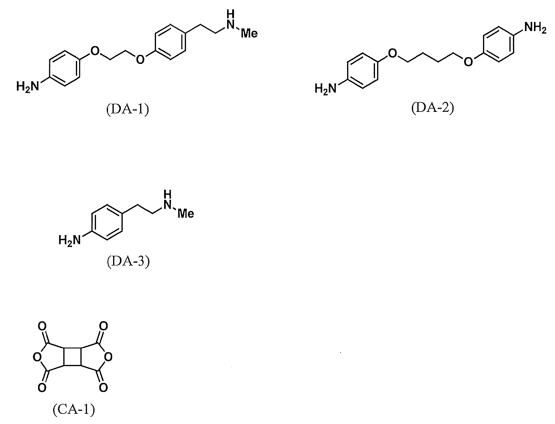
DA-1:下記構造式(DA-1)で表される化合物
DA-2:下記構造式(DA-2)で表される化合物
DA-3:下記構造式(DA-3)で表される化合物
CA-1:下記構造式(CA-1)で表される化合物
装置:フーリエ変換型超伝導核磁気共鳴装置(FT-NMR)「INOVA-400」(Varian製)400MHz。
溶媒:重水素化N,N-ジメチルスルホキシド(DMSO- d6)。
標準物質:テトラメチルシラン(TMS)。
<粘度の測定>
合成例において、重合体溶液の粘度は、E型粘度計TVE-22H(東機産業社製)を用い、サンプル量1.1mL、コーンロータTE-1(1°34’、R24)、温度25℃で測定した。
DA-1は、文献等未公開の新規化合物であり、以下の合成例1でその合成法を詳述する。
[DA-1]:4‐(2-(4-(2-(メチルアミノ)エチル)フェノキシ)エトキシ)アニリンの合成
以下に示す4ステップの経路で芳香族ジアミン化合物(DA-1)を合成した。尚、芳香族ジアミン化合物(DA-1)は、上述した特定ジアミン化合物に該当する。


1H NMR (DMSO- d6):δ 8.22 (d, J = 9.2 Hz, 2H, C6H4), 7.23-7.20 (m, 4H, C6H4), 7.14 (d, J = 8.4 Hz, 2H, C6H4), 6.89 (d, J = 8.4 Hz, 2H, CH2), 4.49-4.47 (m, 2H, CH2), 4.37-4.33 (m, 4H, CH2), 3.10 (s, 3H, CH3), 2.93 (t, J = 6.8 Hz, 2H, CH2).


<合成例2>
撹拌装置及び窒素導入管付きの100mLの四つ口フラスコに、DA-1を1.00g(3.50mmol)、DA-2を2.86g(10.5mmol)量り取り、NMPを37.6g加え、窒素を送りながら撹拌して溶解させた。このジアミン溶液を水冷下で撹拌しながら、CA-1を2.59g(13.2mmol)添加し、さらにNMPを9.41g加え、窒素雰囲気下23℃で15時間撹拌してポリアミック酸の溶液を得た。このポリアミック酸の溶液の温度25℃における粘度は270mPa・sであった。
このポリアミック酸の溶液を撹拌子の入った100mL三角フラスコに14.5g分取し、NMPを12.6g、およびBCSを11.6g加え、マグネチックスターラーで2時間撹拌して、液晶配向剤(A-1)を得た。
撹拌装置及び窒素導入管付きの100mLの四つ口フラスコに、DA-2を4.09g(15.0mmol)量り取り、NMPを39.3g加え、窒素を送りながら撹拌して溶解させた。このジアミン溶液を水冷下で撹拌しながら、CA-1を2.77g(14.1mmol)添加し、さらにNMPを9.83g加え、窒素雰囲気下23℃で3時間撹拌してポリアミック酸の溶液を得た。このポリアミック酸の溶液の温度25℃における粘度は263mPa・sであった。
このポリアミック酸の溶液を撹拌子の入った100mL三角フラスコに14.9g分取し、NMPを12.9g、およびBCSを11.9g加え、マグネチックスターラーで2時間撹拌して、液晶配向剤(B-1)を得た。
撹拌装置及び窒素導入管付きの100mLの四つ口フラスコに、DA-2を2.86g(10.5mmol)、DA-3を0.526g(3.50mmol)量り取り、NMPを34.8g加え、窒素を送りながら撹拌して溶解させた。このジアミン溶液を水冷下で撹拌しながら、CA-1を2.62g(13.4mmol)添加し、さらにNMPを8.71g加え、窒素雰囲気下23℃で15時間撹拌してポリアミック酸の溶液を得た。このポリアミック酸の溶液の温度25℃における粘度は299mPa・sであった。
このポリアミック酸の溶液を撹拌子の入った100mL三角フラスコに14.6g分取し、NMPを12.6g、およびBCSを11.7g加え、マグネチックスターラーで2時間撹拌して、液晶配向剤(B-2)を得た。
以下に、液晶配向性を評価するための液晶セルの作製方法を示す。
FFS方式の液晶表示素子の構成を備えた液晶セルを作製した。初めに、電極付きの基板を準備した。基板は、30mm×35mmの大きさで、厚さが0.7mmのガラス基板である。基板上には第1層目として対向電極を構成する、IZO電極を全面に形成した。第1層目の対向電極の上には、第2層目として、CVD法により成膜したSiN(窒化珪素)膜を形成した。第2層目のSiN膜の膜厚は500nmであり、層間絶縁膜として機能する。第2層目のSiN膜の上には、第3層目として、IZO膜をパターニングして形成した櫛歯状の画素電極を配置し、第1画素及び第2画素の2つの画素を形成した。各画素のサイズは、縦10mm、横約5mmである。このとき、第1層目の対向電極と第3層目の画素電極とは、第2層目のSiN膜の作用により、電気的に絶縁されている。
この液晶セルを用い、70℃の恒温環境下、周波数30Hzで16VPPの交流電圧を120時間印加した。その後、液晶セルの画素電極と対向電極との間を短絡させた状態にし、そのまま23℃で一晩放置した。
放置の後、液晶セルを偏光軸が直交するように配置された2枚の偏光板の間に設置し、電圧無印加の状態でバックライトを点灯させておき、透過光の輝度が最も小さくなるように液晶セルの配置角度を調整した。そして、第1画素の第2領域が最も暗くなる角度から第1領域が最も暗くなる角度まで液晶セルを回転させたときの回転角度を角度Δとして算出した。第2画素でも同様に、第2領域と第1領域とを比較し、同様の角度Δを算出した。そして、第1画素と第2画素の角度Δ値の平均値を液晶セルの角度Δとして算出した。この液晶セルの角度Δの値が0.3°未満の場合には「良好」、角度Δの値が0.3°以上の場合には「不良」と定義し評価した。
ITO電極付きガラス基板を用い、シール剤の印刷前に、片方の基板上の液晶配向膜面に4μmのビーズスペーサーを散布したこと以外は、上記液晶配向性評価用液晶セルの作製と同じ手順で、電圧保持率測定用の液晶セルを作製した。
この液晶セルを用いて、電圧保持率の評価を行った。具体的には、上記の手法で得られた液晶セルに、70℃の温度下で2VPPの交流電圧を60μ秒間印加し、1秒後の電圧を測定し、電圧がどのくらい保持できているかを電圧保持率(VHRともいう)として計算した。なお、測定は、電圧保持率測定装置(VHR-1、東陽テクニカ社製)を使用し、Voltage:±1V、Pulse Width:60μs、Flame Period:1000msの設定で行った。この液晶セルの電圧保持率の値が80%以上の場合には「良好」、電圧保持率の値が80%未満の場合には「不良」と定義し評価した。
合成例2で得られた液晶配向剤(A-1)を用いて、上記記載のように2種類の液晶セルを作製した。偏光紫外線の照射は、高圧水銀灯を用いて、波長選択フィルター:240LCF、および254nmタイプの偏光板を介して行った。偏光紫外線の照射量は、ウシオ電機(株)製照度計UVD-S254SBを用いて光量を測定し、波長254nmで600~1800mJ/cm2の範囲でそれぞれ変更して実施することにより、偏光紫外線照射量が異なる3個以上の液晶セルを作製した。
これらの液晶セルについて、液晶配向性を評価した結果、角度Δが最良だった偏光紫外線照射量は1800mJ/cm2であり、角度Δは0.15°であり良好であった。
また、同じ偏光紫外線照射量で作製した液晶セルについて電圧保持率を評価した結果、電圧保持率は92.4%であり良好であった。
比較合成例1~2で得られた液晶配向剤を用いた以外は、実施例1と同様の方法で、液晶配向性、および電圧保持率を評価した。
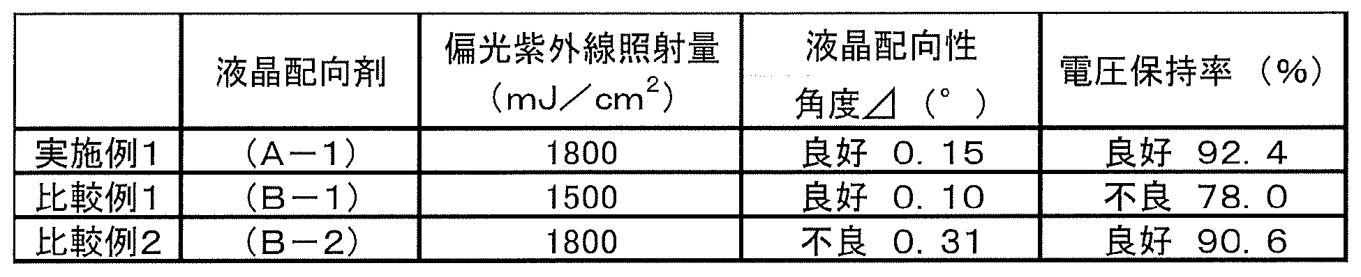
このように本発明の方法によって製造された液晶表示素子は、非常に優れた残像特性を示すことが確認された。
Claims (17)
- 下記式(1)で表される構造を有するジアミンを含むジアミン成分から得られる重合体と、有機溶媒とを含有する、液晶配向剤。

(式(1)中、Xは単結合または2価の有機基であり、Y及びZはそれぞれ独立にアルキレンを含む2価の有機基であり、R1及びR2はそれぞれ独立に1価の有機基であり、R3は炭素数1~4のアルキル基であり、m及びnはそれぞれ独立に0~4の整数である。) - 上記ジアミンを含むジアミン成分とテトラカルボン酸二無水物との重合物であるポリイミド前駆体及びそのイミド化物であるポリイミドからなる群から選ばれる少なくとも1種の重合体と、有機溶媒と、を含有する、請求項1に記載の液晶配向剤。
- 上記ジアミンが、以下の式(2)で表される、請求項1又は2に記載の液晶配向剤。

(式(2)中、X、Y、Z、R1~R3、m及びnの定義は、上記式(1)と同様である。) - 前記ポリイミド前駆体が、下記式(3)で表される請求項1~3のいずれか1項に記載の液晶配向剤。
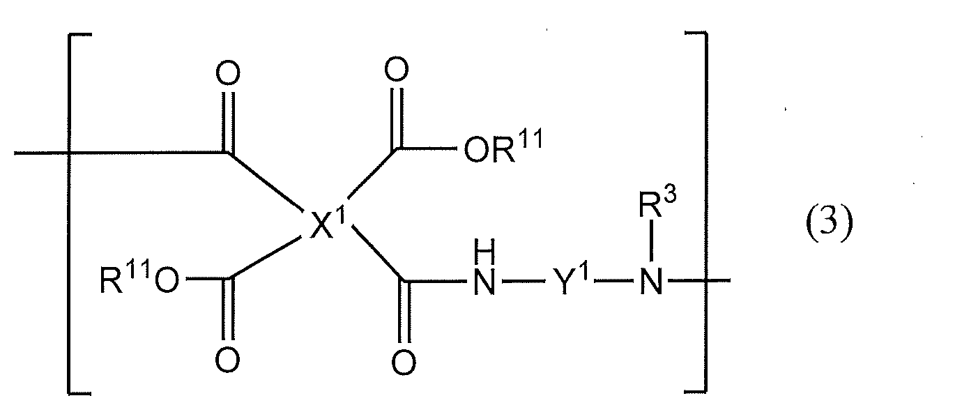
(式(3)において、X1はテトラカルボン酸誘導体に由来する4価の有機基であり、Y1は式(1)の構造を含むジアミンに由来する2価の有機基であり、R11は水素原子又は炭素数1~5のアルキル基であり、R21は炭素数1~4のアルキル基である。) - 前記式(3)中、X1の構造が下記構造式(A-1)乃至(A-21)からなる群から選ばれる少なくとも1種である、請求項4に記載の液晶配向剤。
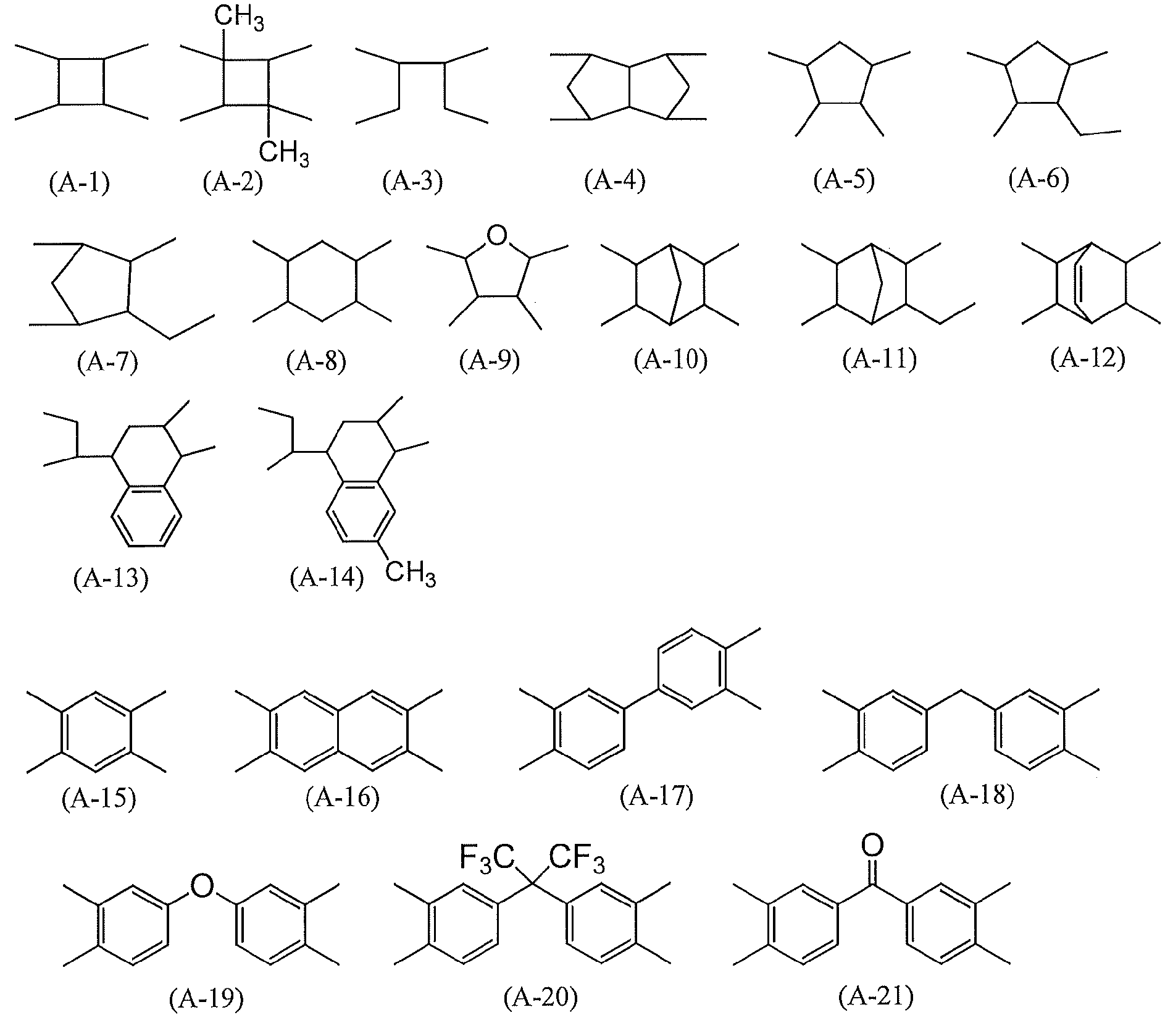
- 前記式(3)で表される構造単位を有する重合体が、液晶配向剤に含有される全重合体に対して10モル%以上含有される、請求項4又は5に記載の液晶配向剤。
- 上記有機溶媒中に、4-ヒドロキシ-4-メチル-2-ペンタノン及びジエチレングリコールジエチルエーテルからなる群から選ばれる少なくとも1種を含有する、請求項4~6のいずれか1項に記載の液晶配向剤。
- [I]請求項1乃至7のいずれか1項記載の組成物を、横電界駆動用の導電膜を有する基板上に塗布して塗膜を形成する工程;
[II] [I]で得られた塗膜に偏光した紫外線を照射する工程;及び
[III] [II]で得られた塗膜を加熱する工程;
を有することによって配向制御能が付与された横電界駆動型液晶表示素子用液晶配向膜を得る、前記液晶配向膜を有する基板の製造方法。 - 請求項8に記載の方法により製造された横電界駆動型液晶表示素子用液晶配向膜を有する基板。
- 請求項9記載の基板を有する、横電界駆動型液晶表示素子。
- 請求項9記載の基板(第1の基板)を準備する工程;
[I’] 第2の基板上に請求項1乃至7のいずれか1項記載の組成物を、塗布して塗膜を形成する工程;
[II’] [I’]で得られた塗膜に偏光した紫外線を照射する工程;及び
[III’] [II’]で得られた塗膜を加熱する工程;
を有することによって配向制御能が付与された液晶配向膜を得る、前記液晶配向膜を有する第2の基板を得る工程;及び
[IV] 液晶を介して前記第1及び第2の基板の液晶配向膜が相対するように、前記第1及び第2の基板を対向配置して液晶表示素子を得る工程;
を有することにより、横電界駆動型液晶表示素子を得る、該液晶表示素子の製造方法。 - 請求項11記載の方法により製造された、横電界駆動型液晶表示素子。
- 下記式(1)で表される構造を有するジアミンを含むジアミン成分とテトラカルボン酸二無水物との重合物であるポリイミド前駆体及びそのイミド化物であるポリイミドからなる群から選ばれる、少なくとも1種の重合体。

(式(1)中、Xは単結合または2価の有機基であり、Y及びZはそれぞれ独立にアルキレンを含む2価の有機基であり、R1及びR2はそれぞれ独立に1価の有機基であり、R3は炭素数1~4のアルキル基であり、m及びnはそれぞれ独立に0~4の整数である。) - 上記ジアミンが、以下の式(2)で表される、請求項13に記載の重合体。

(式(2)中、X、Y、Z、R1~R3、m及びnの定義は、上記式(1)と同様である。) - 前記ポリイミド前駆体が、下記式(3)で表される請求項13又は14に記載の重合体。
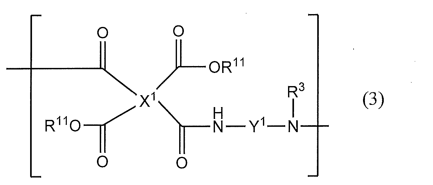
(式(3)において、X1はテトラカルボン酸誘導体に由来する4価の有機基であり、Y1は式(1)の構造を含むジアミンに由来する2価の有機基であり、R11は水素原子又は炭素数1~5のアルキル基であり、R3は炭素数1~4のアルキル基である。) - 前記式(3)中、X1の構造が下記構造式(A-1)乃至(A-21)からなる群から選ばれる少なくとも1種である、請求項15に記載の重合体。

- 下記式(2)で表される、ジアミン。
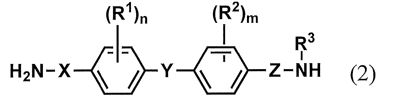
(式(2)中、Xは単結合または2価の有機基であり、Y及びZはそれぞれ独立にアルキレンを含む2価の有機基であり、R1及びR2はそれぞれ独立に1価の有機基であり、R3は炭素数1~4のアルキル基であり、m及びnはそれぞれ独立に0~4の整数である。)
Priority Applications (5)
| Application Number | Priority Date | Filing Date | Title |
|---|---|---|---|
| KR1020197020490A KR102521135B1 (ko) | 2016-12-21 | 2017-12-20 | 액정 배향제, 액정 배향막 및 액정 표시 소자 |
| CN202210349222.9A CN114702393B (zh) | 2016-12-21 | 2017-12-20 | 液晶取向剂、液晶取向膜以及液晶表示元件 |
| CN201780086602.5A CN110300922B (zh) | 2016-12-21 | 2017-12-20 | 液晶取向剂、液晶取向膜以及液晶表示元件 |
| JP2018558020A JP7151485B2 (ja) | 2016-12-21 | 2017-12-20 | 液晶配向剤、液晶配向膜及び液晶表示素子 |
| JP2022000347A JP7279823B2 (ja) | 2016-12-21 | 2022-01-05 | 液晶配向剤、液晶配向膜及び液晶表示素子 |
Applications Claiming Priority (2)
| Application Number | Priority Date | Filing Date | Title |
|---|---|---|---|
| JP2016-248111 | 2016-12-21 | ||
| JP2016248111 | 2016-12-21 |
Publications (1)
| Publication Number | Publication Date |
|---|---|
| WO2018117133A1 true WO2018117133A1 (ja) | 2018-06-28 |
Family
ID=62626326
Family Applications (1)
| Application Number | Title | Priority Date | Filing Date |
|---|---|---|---|
| PCT/JP2017/045625 Ceased WO2018117133A1 (ja) | 2016-12-21 | 2017-12-20 | 液晶配向剤、液晶配向膜及び液晶表示素子 |
Country Status (5)
| Country | Link |
|---|---|
| JP (2) | JP7151485B2 (ja) |
| KR (1) | KR102521135B1 (ja) |
| CN (2) | CN114702393B (ja) |
| TW (1) | TWI746743B (ja) |
| WO (1) | WO2018117133A1 (ja) |
Families Citing this family (1)
| Publication number | Priority date | Publication date | Assignee | Title |
|---|---|---|---|---|
| CN114651207B (zh) * | 2019-11-14 | 2025-03-18 | 日产化学株式会社 | 液晶取向剂、液晶取向膜以及使用该液晶取向膜的液晶显示元件 |
Citations (2)
| Publication number | Priority date | Publication date | Assignee | Title |
|---|---|---|---|---|
| WO2008078796A1 (ja) * | 2006-12-27 | 2008-07-03 | Nissan Chemical Industries, Ltd. | 液晶配向剤、それを用いた液晶配向膜及び液晶表示素子 |
| WO2015050133A1 (ja) * | 2013-10-01 | 2015-04-09 | 日産化学工業株式会社 | 液晶配向剤、液晶配向膜及びそれを用いた液晶表示素子 |
Family Cites Families (10)
| Publication number | Priority date | Publication date | Assignee | Title |
|---|---|---|---|---|
| JP3893659B2 (ja) | 1996-03-05 | 2007-03-14 | 日産化学工業株式会社 | 液晶配向処理方法 |
| AU2003218476A1 (en) * | 2002-05-31 | 2003-12-19 | Elsicon, Inc. | Hybrid polymer materials for liquid crystal alignment layers |
| JP2008176304A (ja) * | 2006-12-22 | 2008-07-31 | Jsr Corp | 液晶配向剤、液晶配向膜、液晶表示素子および光学部材 |
| TWI501998B (zh) * | 2010-03-15 | 2015-10-01 | Nissan Chemical Ind Ltd | A liquid crystal aligning agent containing a polyamic acid ester, and a liquid crystal alignment film |
| KR102168590B1 (ko) * | 2013-03-08 | 2020-10-21 | 닛산 가가쿠 가부시키가이샤 | 액정 배향제, 그들을 사용하여 얻어지는 액정 표시 소자 및 그 제조 방법 |
| KR102214302B1 (ko) * | 2013-05-13 | 2021-02-08 | 닛산 가가쿠 가부시키가이샤 | 횡전계 구동형 액정 표시 소자용 액정 배향막을 갖는 기판의 제조 방법 |
| CN105518521B (zh) * | 2013-07-05 | 2020-04-10 | 日产化学工业株式会社 | 聚合物组合物和横向电场驱动型液晶表示元件用液晶取向膜 |
| TWI746423B (zh) * | 2014-05-29 | 2021-11-21 | 南韓商東進世美肯股份有限公司 | 二胺合成及用其製備的液晶配向劑 |
| JP6676932B2 (ja) * | 2014-11-12 | 2020-04-08 | 日産化学株式会社 | 液晶配向剤、液晶配向膜及び液晶表示素子 |
| WO2016177307A1 (en) * | 2015-05-03 | 2016-11-10 | Adesso Advanced Materials Wuxi Co., Ltd. | Degradable polyurethanes and composites thereof |
-
2017
- 2017-12-20 JP JP2018558020A patent/JP7151485B2/ja active Active
- 2017-12-20 KR KR1020197020490A patent/KR102521135B1/ko active Active
- 2017-12-20 CN CN202210349222.9A patent/CN114702393B/zh active Active
- 2017-12-20 CN CN201780086602.5A patent/CN110300922B/zh active Active
- 2017-12-20 TW TW106144785A patent/TWI746743B/zh active
- 2017-12-20 WO PCT/JP2017/045625 patent/WO2018117133A1/ja not_active Ceased
-
2022
- 2022-01-05 JP JP2022000347A patent/JP7279823B2/ja active Active
Patent Citations (2)
| Publication number | Priority date | Publication date | Assignee | Title |
|---|---|---|---|---|
| WO2008078796A1 (ja) * | 2006-12-27 | 2008-07-03 | Nissan Chemical Industries, Ltd. | 液晶配向剤、それを用いた液晶配向膜及び液晶表示素子 |
| WO2015050133A1 (ja) * | 2013-10-01 | 2015-04-09 | 日産化学工業株式会社 | 液晶配向剤、液晶配向膜及びそれを用いた液晶表示素子 |
Also Published As
| Publication number | Publication date |
|---|---|
| CN110300922B (zh) | 2022-07-01 |
| JP7151485B2 (ja) | 2022-10-12 |
| CN114702393A (zh) | 2022-07-05 |
| KR102521135B1 (ko) | 2023-04-12 |
| CN114702393B (zh) | 2024-12-24 |
| JP7279823B2 (ja) | 2023-05-23 |
| TW201835316A (zh) | 2018-10-01 |
| CN110300922A (zh) | 2019-10-01 |
| TWI746743B (zh) | 2021-11-21 |
| JPWO2018117133A1 (ja) | 2019-10-31 |
| JP2022050521A (ja) | 2022-03-30 |
| KR20190095392A (ko) | 2019-08-14 |
Similar Documents
| Publication | Publication Date | Title |
|---|---|---|
| JP2018045180A (ja) | 液晶配向剤、液晶配向膜および液晶表示素子 | |
| WO2013081067A1 (ja) | 液晶配向膜、液晶配向膜の製造方法、及び液晶表示素子 | |
| JP7315907B2 (ja) | ジアミン及びそれを用いた重合体 | |
| KR102775262B1 (ko) | 액정 배향제, 액정 배향막, 및 액정 표시 소자 | |
| CN119751869A (zh) | 一种聚合物、液晶取向剂、液晶取向膜及液晶表示元件 | |
| JP7768219B2 (ja) | 液晶配向剤、液晶配向膜及び液晶表示素子 | |
| JP7345724B2 (ja) | ジアミン及び重合体 | |
| JP7279823B2 (ja) | 液晶配向剤、液晶配向膜及び液晶表示素子 | |
| TWI848762B (zh) | 新穎聚合物及二胺化合物、液晶配向劑、液晶配向膜及液晶顯示元件 | |
| WO2019139115A1 (ja) | 液晶配向剤、液晶配向膜及び液晶表示素子 | |
| KR102666618B1 (ko) | 액정 배향제, 액정 배향막 및 액정 표시 소자 | |
| JPWO2019198671A1 (ja) | 液晶配向剤、液晶配向膜及びそれを用いた液晶表示素子 | |
| WO2018225810A1 (ja) | 液晶配向剤、液晶配向膜及び液晶表示素子 | |
| JP7488516B2 (ja) | 液晶配向剤、液晶配向膜及び液晶表示素子 | |
| JP7055280B2 (ja) | 液晶配向膜を有する基板の製造方法及び液晶表示素子 | |
| TW202037716A (zh) | 液晶配向劑、液晶配向膜及液晶顯示元件 | |
| JP7779266B2 (ja) | 重合体組成物、液晶配向剤、樹脂膜、液晶配向膜、液晶表示素子の製造方法及び液晶表示素子 | |
| WO2018052105A1 (ja) | 液晶配向剤、液晶配向膜および液晶表示素子 | |
| JP2024070838A (ja) | 液晶配向剤、液晶配向膜及び液晶表示素子 | |
| KR20240101393A (ko) | 액정 배향제, 액정 배향막 및 액정 표시 소자 |
Legal Events
| Date | Code | Title | Description |
|---|---|---|---|
| 121 | Ep: the epo has been informed by wipo that ep was designated in this application |
Ref document number: 17885319 Country of ref document: EP Kind code of ref document: A1 |
|
| ENP | Entry into the national phase |
Ref document number: 2018558020 Country of ref document: JP Kind code of ref document: A |
|
| NENP | Non-entry into the national phase |
Ref country code: DE |
|
| ENP | Entry into the national phase |
Ref document number: 20197020490 Country of ref document: KR Kind code of ref document: A |
|
| 122 | Ep: pct application non-entry in european phase |
Ref document number: 17885319 Country of ref document: EP Kind code of ref document: A1 |