WO2018116913A1 - Système de détection de pression d'air de pneu, dispositif côté véhicule et dispositif côté pneu - Google Patents
Système de détection de pression d'air de pneu, dispositif côté véhicule et dispositif côté pneu Download PDFInfo
- Publication number
- WO2018116913A1 WO2018116913A1 PCT/JP2017/044579 JP2017044579W WO2018116913A1 WO 2018116913 A1 WO2018116913 A1 WO 2018116913A1 JP 2017044579 W JP2017044579 W JP 2017044579W WO 2018116913 A1 WO2018116913 A1 WO 2018116913A1
- Authority
- WO
- WIPO (PCT)
- Prior art keywords
- tire
- side device
- vehicle body
- reception
- unit
- Prior art date
Links
Images


Classifications
-
- B—PERFORMING OPERATIONS; TRANSPORTING
- B60—VEHICLES IN GENERAL
- B60C—VEHICLE TYRES; TYRE INFLATION; TYRE CHANGING; CONNECTING VALVES TO INFLATABLE ELASTIC BODIES IN GENERAL; DEVICES OR ARRANGEMENTS RELATED TO TYRES
- B60C23/00—Devices for measuring, signalling, controlling, or distributing tyre pressure or temperature, specially adapted for mounting on vehicles; Arrangement of tyre inflating devices on vehicles, e.g. of pumps or of tanks; Tyre cooling arrangements
- B60C23/02—Signalling devices actuated by tyre pressure
- B60C23/04—Signalling devices actuated by tyre pressure mounted on the wheel or tyre
- B60C23/0408—Signalling devices actuated by tyre pressure mounted on the wheel or tyre transmitting the signals by non-mechanical means from the wheel or tyre to a vehicle body mounted receiver
- B60C23/0415—Automatically identifying wheel mounted units, e.g. after replacement or exchange of wheels
- B60C23/0416—Automatically identifying wheel mounted units, e.g. after replacement or exchange of wheels allocating a corresponding wheel position on vehicle, e.g. front/left or rear/right
-
- B—PERFORMING OPERATIONS; TRANSPORTING
- B60—VEHICLES IN GENERAL
- B60C—VEHICLE TYRES; TYRE INFLATION; TYRE CHANGING; CONNECTING VALVES TO INFLATABLE ELASTIC BODIES IN GENERAL; DEVICES OR ARRANGEMENTS RELATED TO TYRES
- B60C23/00—Devices for measuring, signalling, controlling, or distributing tyre pressure or temperature, specially adapted for mounting on vehicles; Arrangement of tyre inflating devices on vehicles, e.g. of pumps or of tanks; Tyre cooling arrangements
- B60C23/02—Signalling devices actuated by tyre pressure
- B60C23/04—Signalling devices actuated by tyre pressure mounted on the wheel or tyre
- B60C23/0408—Signalling devices actuated by tyre pressure mounted on the wheel or tyre transmitting the signals by non-mechanical means from the wheel or tyre to a vehicle body mounted receiver
- B60C23/0422—Signalling devices actuated by tyre pressure mounted on the wheel or tyre transmitting the signals by non-mechanical means from the wheel or tyre to a vehicle body mounted receiver characterised by the type of signal transmission means
- B60C23/0433—Radio signals
- B60C23/0447—Wheel or tyre mounted circuits
- B60C23/0455—Transmission control of wireless signals
-
- B—PERFORMING OPERATIONS; TRANSPORTING
- B60—VEHICLES IN GENERAL
- B60C—VEHICLE TYRES; TYRE INFLATION; TYRE CHANGING; CONNECTING VALVES TO INFLATABLE ELASTIC BODIES IN GENERAL; DEVICES OR ARRANGEMENTS RELATED TO TYRES
- B60C23/00—Devices for measuring, signalling, controlling, or distributing tyre pressure or temperature, specially adapted for mounting on vehicles; Arrangement of tyre inflating devices on vehicles, e.g. of pumps or of tanks; Tyre cooling arrangements
- B60C23/02—Signalling devices actuated by tyre pressure
- B60C23/04—Signalling devices actuated by tyre pressure mounted on the wheel or tyre
- B60C23/0408—Signalling devices actuated by tyre pressure mounted on the wheel or tyre transmitting the signals by non-mechanical means from the wheel or tyre to a vehicle body mounted receiver
- B60C23/0422—Signalling devices actuated by tyre pressure mounted on the wheel or tyre transmitting the signals by non-mechanical means from the wheel or tyre to a vehicle body mounted receiver characterised by the type of signal transmission means
- B60C23/0433—Radio signals
- B60C23/0435—Vehicle body mounted circuits, e.g. transceiver or antenna fixed to central console, door, roof, mirror or fender
- B60C23/0438—Vehicle body mounted circuits, e.g. transceiver or antenna fixed to central console, door, roof, mirror or fender comprising signal transmission means, e.g. for a bidirectional communication with a corresponding wheel mounted receiver
- B60C23/044—Near field triggers, e.g. magnets or triggers with 125 KHz
-
- B—PERFORMING OPERATIONS; TRANSPORTING
- B60—VEHICLES IN GENERAL
- B60C—VEHICLE TYRES; TYRE INFLATION; TYRE CHANGING; CONNECTING VALVES TO INFLATABLE ELASTIC BODIES IN GENERAL; DEVICES OR ARRANGEMENTS RELATED TO TYRES
- B60C23/00—Devices for measuring, signalling, controlling, or distributing tyre pressure or temperature, specially adapted for mounting on vehicles; Arrangement of tyre inflating devices on vehicles, e.g. of pumps or of tanks; Tyre cooling arrangements
- B60C23/02—Signalling devices actuated by tyre pressure
- B60C23/04—Signalling devices actuated by tyre pressure mounted on the wheel or tyre
- B60C23/0408—Signalling devices actuated by tyre pressure mounted on the wheel or tyre transmitting the signals by non-mechanical means from the wheel or tyre to a vehicle body mounted receiver
- B60C23/0422—Signalling devices actuated by tyre pressure mounted on the wheel or tyre transmitting the signals by non-mechanical means from the wheel or tyre to a vehicle body mounted receiver characterised by the type of signal transmission means
- B60C23/0433—Radio signals
- B60C23/0447—Wheel or tyre mounted circuits
- B60C23/045—Means for detecting electromagnetic field changes being not part of the signal transmission per se, e.g. strength, direction, propagation or masking
-
- G—PHYSICS
- G08—SIGNALLING
- G08C—TRANSMISSION SYSTEMS FOR MEASURED VALUES, CONTROL OR SIMILAR SIGNALS
- G08C17/00—Arrangements for transmitting signals characterised by the use of a wireless electrical link
-
- G—PHYSICS
- G08—SIGNALLING
- G08C—TRANSMISSION SYSTEMS FOR MEASURED VALUES, CONTROL OR SIMILAR SIGNALS
- G08C17/00—Arrangements for transmitting signals characterised by the use of a wireless electrical link
- G08C17/02—Arrangements for transmitting signals characterised by the use of a wireless electrical link using a radio link
Definitions
- This disclosure relates to a tire pressure detection system.
- Tire pressure warning system (TPMS: TireTPressure Monitoring ⁇ ⁇ System) that detects the air pressure of multiple tires mounted on the vehicle and issues a warning when the detected air pressure is abnormal is used.
- Patent Document 1 is provided with a detection device including a sensor provided in each tire, a monitoring device on the vehicle body side that receives a detection signal from the detection device, and in the vicinity of each tire.
- a tire pressure alarm system is disclosed that includes a transmitter (LF antenna) that transmits a Low (Frequency) signal.
- LF antenna Low (Frequency) signal.
- an LF signal is sequentially transmitted from each transmitter to a corresponding detection device, and the detection device that has received the LF signal responds to the monitoring device with an RF (Radio Frequency) signal.
- RF Radio Frequency
- Patent Document 1 discloses that a response signal to an LF signal (trigger signal) transmitted from a transmitter corresponding to each detection device includes the reception intensity of the trigger signal, and is included in the response signal. When the intensity is within a predetermined range, the ID of the detection device included in the response signal is registered.
- the present invention has been made in view of such circumstances. While using the reception intensity on the tire side, each tire is accurately identified without setting a threshold value or a reception intensity range for the reception intensity. It is an object of the present invention to provide a tire air pressure detection system, a vehicle body side device, and a tire side device that can detect each air pressure.
- a tire air pressure detection system is provided in each of a plurality of tires mounted on a vehicle, and a sensor that detects the air pressure of the tire and a signal that requests transmission of a measurement result by the sensor.
- a sensor that detects the air pressure of the tire and a signal that requests transmission of a measurement result by the sensor.
- Is provided on the vehicle body of the vehicle and is provided on the vehicle body of the vehicle, and is provided on the vehicle body of the vehicle.
- a vehicle body side device having a vehicle body side transmitter and a vehicle body side receiver for transmitting and receiving signals wirelessly, and acquiring the air pressure of each tire by the vehicle body side device, and reducing the air pressure Tire pressure detection system, wherein each of the tire side devices stores a first storage unit for storing an identifier for identifying the device itself, and reception strength of each of the measurement signals.
- a receiving intensity measuring unit that measures the number of signals, a specifying unit that specifies the number of measurement signals received by the tire side receiving unit, and a tire side device corresponding to the plurality of tires are sequentially transmitted from the vehicle body side device.
- a second storage unit that stores the number of measurement signals among the measurement signals to be received and a reception order of receiving the measurement signals having the strongest reception strength among the measurement signals that can be received, and the second storage unit
- a tire-side transmission control unit that transmits information indicating the number of signals for measurement and the order of reception stored in the first storage unit and a response signal including an identifier stored in the first storage unit to the vehicle-side device
- the apparatus includes: a vehicle body side transmission control unit that sequentially transmits measurement signals from the vehicle body side transmission unit to the tire side devices of the plurality of tires according to the destination order; and the vehicle body side reception unit after transmitting the measurement signals.
- Receive response signal The vehicle body side reception control unit, the identifier included in each of the response signals transmitted from the plurality of tire side devices, the number of signals for measurement and the reception order, and the tire position corresponding to the destination order based on the comparison and the tire position And a control unit that associates the identifier.
- a vehicle body side device is provided on a vehicle body of a vehicle, and transmits and receives information with a tire side device provided on each of a plurality of tires attached to the vehicle by radio signals.
- a transmission control unit that sequentially transmits measurement signals from the transmission unit according to a predetermined destination order to the tire side devices of the plurality of tires, and after transmission of the measurement signals.
- the reception control unit that receives the response signal by the reception unit, the identifier included in the response signal transmitted from the plurality of tire side devices, the number of measurement signals and the reception order are extracted, and the number of measurement signals and the reception order that are extracted And a control unit that associates the tire position corresponding to the predetermined destination order with the identifier based on the mutual comparison.
- a tire-side device is provided on a tire of a vehicle, and includes a transmission unit and a reception unit that transmit and receive information with a vehicle body-side device provided on a vehicle body of the vehicle by radio signals.
- a first storage unit for storing an identifier for identifying the device itself, a reception intensity measurement unit for measuring the reception intensity of each of the measurement signals, and the number of measurement signals received by the reception unit Among the measurement signals that are sequentially transmitted from the vehicle body side device to the tire side device, the number of the specified measurement signals and the highest received intensity among the measurement signals that can be received
- a second storage unit for storing the reception order of receiving the measurement signals; information indicating the number of measurement signals and the reception order stored in the second storage unit; and an identifier stored in the first storage unit Response signal for body side equipment And a transmission control unit for signal.
- the present application can be realized not only as a tire air pressure detection system including such characteristic components, but also as a vehicle body side device and a tire side device constituting the system, and a tire including such characteristic steps. It can be realized as an air pressure detection method, or as a program for causing a computer to execute such steps. Also realized as a semiconductor integrated circuit that realizes part or all of a tire pressure detection system, a vehicle body side device, and a tire side device, or as a tire pressure detection system, a vehicle body side device, or other system including a tire side device. You can do it.
- FIG. 4 is an explanatory diagram highlighting a case where the FLAG data in FIG. 3 is “010”.
- a tire air pressure detection system is provided in each of a plurality of tires mounted on a vehicle, and a sensor that detects the air pressure of the tire and transmission of a measurement result by the sensor.
- a tire-side receiving unit that wirelessly receives a request signal; and a tire-side device that includes a tire-side transmitting unit that wirelessly transmits a measurement result in response to the request; and a vehicle body of the vehicle.
- a vehicle body side device that is provided in a vehicle body and includes a vehicle body side transmission unit and a vehicle body side reception unit that wirelessly transmit and receive signals, and obtains the air pressure of each tire by the vehicle body side device;
- a tire air pressure detection system for detecting a decrease in air pressure, wherein each of the tire side devices stores a first storage unit that stores an identifier for identifying the device itself, and each of the measurement signals.
- a reception strength measuring unit that measures signal strength, a specifying unit that specifies the number of measurement signals that can be received by the tire-side receiving unit, and a tire-side device corresponding to the plurality of tires from the vehicle body-side device sequentially
- a second storage unit for storing the number of measurement signals transmitted among the measurement signals to be transmitted, and the reception order of receiving the measurement signals having the strongest reception intensity among the measurement signals received;
- a tire-side transmission control unit that transmits information indicating the number of measurement signals stored in the storage unit and the reception order, and a response signal including an identifier stored in the first storage unit to the vehicle body-side device
- the vehicle body side device includes a vehicle body side transmission control unit that sequentially transmits measurement signals from the vehicle body side transmission unit according to the destination order to the tire side devices of the plurality of tires, and the vehicle body side reception after the measurement signals are transmitted.
- the vehicle body side reception control unit for receiving, the identifier included in each of the response signals transmitted from a plurality of tire side devices, the number of signals for measurement and the reception order are extracted, and the tire position corresponding to the destination order based on the comparison, And a control unit that associates the identifier.
- a measurement signal is transmitted from the vehicle body side device to each tire side device, and the tire side device measures the received intensity of the received signal, and measures the received signal.
- the number of received signals and the reception order of the signals having the strongest reception strength are stored.
- Each of the tire side devices transmits the number of measurement signals stored in the own device and information on the reception order together with an identifier for identifying the own device as a response to the vehicle body side device.
- the signal addressed to the device is not in the first destination order, and conversely the signal for measurement after the signal with the strong reception strength. , It can be determined that the signal addressed to the device is not in the last destination order.
- the control unit transmits a plurality of response signals after transmitting a request signal requesting transmission of a measurement result to any one of the tire side devices. Is stored, the correspondence between the tire position corresponding to the request destination of the request signal and the identifier included in the response signal is stored, the identifier included in the response signal, the number of measurement signals, and the reception order Based on the correspondence between the stored tire position and the identifier, the tire position corresponding to the destination order is associated with the identifier.
- Information on the identifier of the tire side device is stored.
- the vehicle body side device can more accurately determine the tire position of the tire in which each tire side device is provided by referring to the information transmitted at the time of occurrence of the crosstalk with respect to the candidate transmitted from each tire side device.
- a vehicle body side device is provided in a vehicle body of a vehicle, and transmits / receives information to / from a tire side device provided in each of a plurality of tires attached to the vehicle by radio signals.
- a vehicle body side device including a transmission unit and a reception unit, wherein the measurement signal is sequentially transmitted from the transmission unit to the tire side device of the plurality of tires according to a predetermined destination order; and the measurement signal
- the reception control unit that receives the response signal by the receiving unit after transmission of the identifier, the identifier included in the response signal transmitted from the plurality of tire side devices, the number of measurement signals and the order of reception, and the number of measurement signals extracted And a control unit for associating the tire position corresponding to the predetermined destination order with the identifier based on the mutual comparison of the reception order.
- a measurement signal is transmitted from the vehicle body side device to each tire side device, and the signals received by the tire side device can be measured.
- the number of signals for use and the signal having the strongest reception strength, that is, the reception order of the signals addressed to the own apparatus are stored.
- the vehicle body side device can further determine the tire position of the tire provided with each tire side device according to the exclusion method from the comparison of the number of signals for measurement stored in each tire side device and the receiving order.
- a tire-side device in a vehicle tire, and includes a transmission unit and a reception unit that transmit and receive information to and from the vehicle-side device provided in the vehicle body by radio signals.
- a first storage unit that stores an identifier for identifying the own device, a reception intensity measurement unit that measures the reception intensity of each of the measurement signals, and a measurement signal received by the reception unit
- a specifying unit for specifying the number, and among the measurement signals sequentially transmitted from the vehicle body side device to the tire side device, the number of the specified measurement signals and the most received of the measurement signals received
- a second storage unit that stores the reception order of receiving the measurement signals having high strength, information indicating the number of measurement signals stored in the second storage unit and the reception order, and the first storage unit Response signal including identifier
- a transmission control unit for transmitting to only.
- the tire-side device transmits the stored number of measurement signals and the signal having the strongest reception strength, that is, the reception order of the signals addressed to itself to the vehicle-side device as a response signal.
- the vehicle body side device compares these pieces of information to determine the correspondence between the tire position and the tire side device identifier.
- FIG. 1 is a schematic diagram showing an arrangement of components of a tire air pressure detection system 100 in the present embodiment.
- the tire air pressure detection system 100 includes a vehicle body side device 1 and a number of tire side devices 2 corresponding to the number of tires T mounted.
- the vehicle body side device 1 is installed inside or below the instrument panel.
- the vehicle body side device 1 is connected to transmission antennas 31 to 34 provided in a tire house of each tire T by signal lines.
- the transmission antenna 31 is located at the position corresponding to the right front tire T
- the transmission antenna 32 is located at the position corresponding to the right rear tire T
- the transmission antenna 33 is located at the position corresponding to the left rear tire T
- the transmission antenna 34 is located at the left front tire T. It is provided at the corresponding position.
- the transmission antennas 31 to 34 are antennas that transmit radio signals to the tire side device 2.
- an LF (Low ⁇ Frequency) band (for example, 125 kHz) is used as a frequency band of a carrier wave of a signal transmitted from the transmission antennas 31 to 34.
- the frequency band is not limited to this, but it is preferable to use a frequency band that is different from the receiving antenna 4 described later and that has significant attenuation due to distance.
- the vehicle body side device 1 is also connected to a receiving antenna 4 provided on the roof of the vehicle V by a signal line.
- the receiving antenna 4 is provided in the lining of the roof of the vehicle V, for example.
- the receiving antenna 4 receives a signal transmitted from the tire side device 2.
- the frequency band of the received carrier wave is an RF (RadioRadFrequency) band (for example, 300 MHz, UHF band).
- the frequency band is not limited to this.
- the tire side device 2 is a sensor unit that is provided inside each wheel of the tire and measures the air pressure of each tire by a pressure sensor using a diaphragm, for example, and transmits the air pressure signal of the measurement result wirelessly.
- FIG. 2 is a block diagram showing a configuration of the tire air pressure detection system 100 in the present embodiment.
- the vehicle body side device 1 is a so-called BCM (Body Control Module) unit that integrally performs control of locking / unlocking of the door lock of the vehicle V and control of body system actuators such as in-vehicle and external lights.
- the vehicle body side device 1 includes a control unit 10, a storage unit 11, an output unit 12, a reception unit 14, and a transmission unit 13, and operates by receiving power supply from a battery.
- BCM Body Control Module
- the control unit 10 is, for example, a microcontroller that uses one or a plurality of CPUs (Central Processing Unit) or a multi-core CPU, and has a ROM (Read Only Memory), a RAM (Random Access Memory), an input / output interface, a timer, and the like.
- the control unit 10 controls each component based on the control program 1P stored in the storage unit 11.
- the control program 1P may be stored in a built-in ROM of the control unit 10.
- the storage unit 11 uses a non-volatile memory such as a flash memory.
- the storage unit 11 stores various types of information referred to by the control unit 10 and the above-described control program 1P.
- the correspondence between the identifier 241 transmitted from each tire-side device 2 and the identification information of each tire T (the tire positions such as front right, front left, rear right, rear left, spare, etc.) Is memorized.
- the control program 1P stored in the storage unit 11 may be recorded in the computer-readable recording medium 5.
- the storage unit 11 stores a control program 5P read from the recording medium 5 by a reading device (not shown).
- the recording medium 5 is an optical disc such as CD (Compact Disc) -ROM, DVD (Digital Versatile Disc) -ROM, BD (Blu-ray (registered trademark) Disc), a flexible disc, a magnetic disc such as a hard disc, a magnetic optical disc, and a semiconductor memory. Etc. Further, the control program 5P according to the first embodiment may be downloaded from an external computer (not shown) connected to a communication network (not shown) and stored in the storage unit 11.
- CD Compact Disc
- DVD Digital Versatile Disc
- BD Blu-ray (registered trademark) Disc
- the display unit 61 and the speaker 62 are connected to the output unit 12. Only one of the display 61 and the speaker 62 may be provided.
- the output unit 12 outputs a control signal to the display 61 and outputs an audio signal to the speaker 62 under the control of the control unit 10.
- the display 61 is an indicator lamp provided in the instrument panel including the speedometer on the instrument panel. You may use LED (Light * Emitting * Diode). A head-up display may also be used.
- the display 61 is a type incorporating a touch panel used in a navigation system or the like, and may use a display panel such as an LCD (Liquid Crystal Display) or an organic EL (Electro Luminescence). The display 61 displays an image or a character based on the signal output from the output unit 12.
- the speaker 62 emits sound or sound effect based on the signal output from the output unit 12.
- the transmission unit 13 is connected to transmission antennas 31 to 34, and uses a transmission module including a modulator that modulates signals transmitted from the transmission antennas 31 to 34.
- the transmission unit 13 has a switching unit 13a therein, and any one or all of the plurality of transmission antennas 31 to 34 can be selected and used by the switching unit a.
- the transmission unit 13 has a selection unit 13b that can select a signal output, and the selection unit 13b selects the transmission intensity from each of the transmission antennas 31 to 34 from a plurality of output stages (strong and weak). Can be made.
- the receiving unit 14 is connected to the receiving antenna 4 and uses a receiving circuit including an amplifier, a filter circuit, and a demodulator for radio waves received by the receiving antenna 4.
- the tire side device 2 includes a control unit 20, a sensor 21, a transmission unit 23, a reception unit 22, a storage unit 24, and a reception intensity measurement unit 25.
- the tire side device 2 operates by receiving power supply from a battery or a built-in battery.
- the control unit 20 is a microcontroller using, for example, one or a plurality of CPUs or a multi-core CPU and having a ROM, a RAM, an input / output interface, a timer, and the like.
- the CPU of the control unit 20 is connected to the sensor 21, the reception unit 22, the transmission unit 23, and the storage unit 24 via an input / output interface.
- the sensor 21 uses a diaphragm, for example, and measures the air pressure of the tire T based on the amount of deformation of the diaphragm that changes depending on the magnitude of pressure.
- the sensor 21 outputs the measurement result as a signal (having a voltage level corresponding to the air pressure) to the control unit 20.
- the sensor 21 may further be configured to output a signal indicating temperature to the control unit 20 using a temperature sensor.
- the storage unit 24 is a nonvolatile memory such as a flash memory.
- the storage unit 24 stores a control program 2P for causing the control unit 20 to control the operation of each component of the tire-side device 2, that is, for executing processing for transmitting and receiving tire pressure measurement results described later.
- the storage unit 24 stores in advance a unique identifier 241 so that the plurality of tire-side devices 2 can be identified from each other.
- the control unit 20 and the storage unit 24 are illustrated as separate components.
- the control unit 20 may include the storage unit 24, and the control program 2 ⁇ / b> P and the identifier 241 may be controlled. It may be stored in the built-in storage unit of the unit 20.
- the storage unit 24 stores flag data indicating the number of measurement signals transmitted from the vehicle body side device 1 and the reception order of the strongest signal among them (FIG. 3). reference).
- the receiving unit 22 removes a carrier wave component from a plurality of radio signals received by the antenna 22a, extracts the received signal, and outputs the extracted received signal to the control unit 20.
- the LF band is used as the frequency band of the carrier wave of the radio signal received by the antenna 22a.
- the frequency band of the carrier wave received by the antenna 22a is not limited to this frequency band as long as it corresponds to the transmission antennas 31 to 34 on the vehicle body side.
- the transmission unit 23 is a circuit that modulates a signal input from the control unit 20 using a carrier wave and transmits a radio signal through the transmission antenna 23a.
- the RF band (UHF band) is used as the frequency band of the carrier wave of the signal transmitted from the transmission antenna 23a.
- the frequency band used for the transmission antenna 23a is not limited to this frequency band as long as it corresponds to the reception antenna 4 on the vehicle body side.
- the reception intensity measurement unit 25 measures the reception intensity of the radio signal received by the antenna 22a using an amplifier circuit or the like, and outputs it to the control unit 20.
- the control unit 10 of the vehicle body side device 1 periodically acquires the air pressure of each tire T. For example, the control unit 10 of the vehicle body side apparatus 1 sequentially transmits a transmission request for the measurement result to the tire side apparatus 2 of each tire T from the transmission antennas 31 to 31 using an LF signal.
- the tire 21 measures the measurement result obtained by the sensor 21 together with the identifier 241 stored in the storage unit 24 from the transmission antenna 23a of the transmission unit 23 using an RF signal.
- Send The control unit 10 of the vehicle body side apparatus 1 receives a response with an RF signal at the reception unit 14 via the reception antenna 4, and identifies which tire T is the measurement result based on the information of the identifier 241.
- the control part 10 acquires the air pressure of each tire T, it will compare with the threshold value of an air pressure fall, and when it is judged that it is below a threshold value, the alarm which shows that the tire T is reducing the air pressure will be output.
- 12 is output from the display 61 or the speaker 62.
- the alarm includes information for specifying the tire position of the tire T in which the air pressure drop has occurred.
- the display 61 turns on a warning light indicating one of the four wheels, or displays character information such as “the air pressure of the right front tire has decreased”.
- the speaker 62 outputs, for example, a sound effect together with the warning light, or outputs a voice reading “The air pressure of the right front tire has decreased”.
- the threshold value referred to in the comparison may be a threshold value corresponding to the type of the vehicle V and the tire T. In this way, it is possible to inform the user of the need for maintenance of the tire T in which a decrease in air pressure has occurred. In addition, it is also possible to perform appropriate traveling control by notifying the traveling control system of the vehicle V of the decrease in air pressure.
- the identifier 241 received together with the measurement result signal from the tire side device 2 corresponds to the tire positions of the right front, right rear, left rear, and left front (further, a spare may be included). It is necessary to be attached and stored (registered) in the storage unit 11. This is because the relationship between the tire side device 2 and the tire position is not fixed because the tire T can be replaced with the entire wheel. Registration of the correspondence between the identifier 241 and the tire position is initially registered (at the time of shipment), but other than that, the vehicle body side device 1 detects that crosstalk has occurred with the tire side device 2. If you do.
- the occurrence of crosstalk is caused by, for example, a case where the control unit 10 of the vehicle body side apparatus 1 transmits a measurement value request signal from the transmission antenna 31 to the tire side apparatus 2 corresponding to the right front tire T. This is detected when the measurement result is transmitted from the side apparatus 2 as a response signal. At this time, the control unit 10 of the vehicle body side device 1 stores the identifiers 241 corresponding to the plurality of tire side devices 2 that have responded to the transmission request in association with information indicating the destination of the transmission request.
- control unit 10 may detect this and may carry out automatically.
- FIG. 3 is an explanatory diagram for explaining information stored in the storage unit 24 of the tire-side device 2.
- the crosstalk is not the destination tire T, although the measurement value request signal is transmitted from any of the transmission antennas 31 to 34 to the tire side device 2 corresponding to the destination tire T.
- This is a phenomenon in which the request signal reaches the tire side device 2 corresponding to the tire T and the measurement result is transmitted as a response signal. Therefore, the tire side device 2 measures the reception status of signals from the vehicle body side device 1 to other devices.
- FIG. 1 is an explanatory diagram for explaining information stored in the storage unit 24 of the tire-side device 2.
- FIG. 3 shows a reception situation in each tire side device 2 when a specific signal (measurement signal) is transmitted from the vehicle body side device 1 in a predetermined order. It is assumed that the specific signal is transmitted from the right front (FR) transmission antenna 31 in the order of rear right (RR), rear left (RL), and front left (FL). The reception status of these signals is listed in the receiving unit 22 of each tire side device 2 as shown in FIG.
- the combination is the nearest right front tire.
- the signal transmitted from the transmission antenna 31 of the right front tire T (FR) can always be received first, and the reception intensity should be the strongest.
- the control unit 20 stores FLAG data corresponding to the number of signals that can be received and the order of the signals having the strongest reception strength. In the example of FIG. 3, “10” is stored as FLAG data in the storage unit 24 of the tire side device 2 of the right front tire T.
- the FLAG data may be composed of 4-bit information indicating the number of signals that can be received and 4-bit information corresponding to the order of the reception intensity, or 16 bits (2 Byte) may represent “1” or “0” by 4 bits.
- 0x10ff 0xadecimal
- the reception unit 22 of the tire side device 2 of the right front tire T can receive three of the specific signals transmitted from the transmission antennas 31 to 34, the combination of the right front tire T (FR) A signal transmitted from the transmission antenna 31 and a signal transmitted from any other.
- the signal transmitted from the transmission antenna 31 of the right front tire T (FR) can always be received first, and the reception intensity should be the strongest. Therefore, in this case, “100” is stored for all FLAG data.
- the signal transmitted from the transmitting antenna 31 of the right front tire T (FR) is received first, and the reception strength is the strongest. . In this case, “1000” is stored for all FLAG data.
- the order in which the signals transmitted from the transmission antenna 32 of the right rear tire T (RR) can be received is the first and second.
- a signal transmitted from the transmission antenna 32 of the right rear tire T (RR) can be received with the strongest reception strength, but the reception order is not determined.
- the combination is the signal transmitted from the transmitting antenna 32 of the latest right rear tire T (RR) and any other signal. It is a signal transmitted from Although the signal transmitted from the transmitting antenna 32 can be received most strongly, the receiving order is not the third as shown in FIG. 3, but the first and second are not determined.
- candidates for the destination order of the strongest received signal can be narrowed down from the number of received signals and the order of the signals that have been received most strongly.
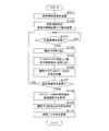
- FIG. 4 and 5 are flowcharts showing an example of registration processing of the identifier 241 and the tire position performed in the tire air pressure detection system 100.
- FIG. In the flowchart of FIG. 3, a processing procedure in the vehicle body side device 1 is shown.
- the control unit 10 of the vehicle body side device 1 causes the transmission unit 13 to transmit measurement start signals all at once from all the transmission antennas 31 to 34 to all the tire side devices 2 (step S101).
- the measurement start signal is a signal for starting measurement of the reception status in the tire side device 2 thereafter.
- the control unit 10 then transmits the measurement signals corresponding to the measurement signals according to a predetermined destination order (for example, right front (FR), right rear (RR), left front (FL), left rear (RL)) after a suitable standby time. Transmission is sequentially performed with a predetermined interval from 31 to 34 (step S102). At this time, the measurement signal is transmitted from each of the transmission antennas 31 to 34 with the same transmission intensity. Moreover, the transmission intensity
- control part 10 judges whether the response signal was received by the receiving antenna 4 from any tire side apparatus 2 after step S102 (step S103).
- step S103 If it is determined in step S103 that a response signal has not been received (S103: NO), the control unit 10 returns the process to step S103 and waits until it is determined that a response signal has been received.
- step S103 If it is determined in step S103 that a response signal has been received (S103: YES), the control unit 10 extracts information on the identifier 241 from the response signal received by the reception unit 14 (step S104). Further, the control unit 10 extracts FLAG data from the response signal (step S105), and stores the correspondence with the FLAG data transmitted together with the identifier 241 in the storage unit 24 (step S106). The control unit 10 determines whether or not a response signal to the measurement signal for all tires T has been received (step S107).
- step S107 If it is determined in step S107 that it has not been received (S107: NO), the control unit 10 returns the process to step S102, selects the next tire T, and executes the process.
- step S107 If it is determined in step S107 that the signal has been received (S107: YES), the control unit 10 sends a reply to the destination of the transmission request stored at the time of occurrence of crosstalk stored in the storage unit 24 and the destination. Reference is made to the correspondence with the identifier 241 of the tire side device 2 that has been made (step S108).
- the control unit 10 determines the destination based on the correspondence between the identifier 241 stored in step S106 and the FLAG data (the number and reception order received), the destination order referred to in step S108, and the correspondence between the returned device identifier 241.
- the correspondence between the order and the identifier 241 corresponding thereto is determined (step S109). The determination method in step S109 will be described in detail later.
- the control unit 10 stores the determined correspondence in the storage unit 24 (step S110), and ends the process.
- the correspondence stored in the storage unit 24 is used in the subsequent air pressure detection process.
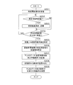
- step S201 when receiving the measurement start signal by the receiving unit 22 (step S201), the control unit 20 determines whether or not the measurement signal is received from any of the transmission antennas 31 to 34 (step S201). Step S202). When it is determined in step S202 that the measurement signal is not received (S202: NO), the control unit 20 advances the process to step S204.
- the control unit 20 measures the received measurement signal by the received intensity measurement unit 25 and stores it in time series (step S203).
- the reception intensity measurement unit 25 measures and continuously outputs the reception intensity of the radio signal received by the reception unit 22, and the control unit 20 acquires the corresponding reception intensity.
- control unit 20 determines whether a predetermined time has elapsed after receiving the measurement start signal, or whether the measurement signals from all the transmission antennas 31 to 34 have been received (step S204). When it is determined that the predetermined time has not elapsed and all the measurement signals have not been received (S204: NO), the control unit 20 returns the process to step S202, for a total of four measurement signals. Until the predetermined time elapses.
- step S204 When it is determined in step S204 that the predetermined time has elapsed or that all the request signals have been received (S204: YES), the control unit 20 is based on the reception strength of each measurement signal stored in time series. Then, the number of received measurement signals is specified (step S205). Further, the control unit 20 specifies the reception order of the measurement signals received with the strongest reception strength (step S206).
- control unit 20 stores the FLAG data including the specified number of measurement signals and the reception order of the strongest signal in the storage unit 24 (step S207).
- the FLAG data may be temporarily stored in the built-in RAM.
- control unit 20 reads the identifier 241 from the storage unit 24 (step S208), and transmits a response signal including the FLAG data and the identifier 241 toward the vehicle body side device 1 (receiving antenna 4) (step S209). The process is terminated.
- the control unit 10 of the vehicle body side device 1 transmits a transmission request to the tire side device 2 of each tire T in the order of the transmission antennas 31, 32, 33, and 34. .
- responses from a plurality of tire-side devices 2 are received, as well as responses from measurement results not only from the right front (FR) but also from the right rear (RR) and left front (FL) tire-side devices 2.
- the control unit 10 recognizes the occurrence of the crosstalk, but stores the identifier 241 and the FLAG data of each tire side device 2 that responds in association with the destination information (for example, FR), and specifies the following procedure. .
- the control unit 10 performs crosstalk on a signal from the transmission antenna 31 provided closest to the right front (FR) tire T in which the destination order is first.
- FLAG data from the tire side device 2 involved in the process is referred to.
- the FLAG data has the following pattern.
- the FLAG data that can be recorded by the tire-side device 2 in each tire T when the signal from the transmitting antenna 31 can be received (the leftmost bar graph is present) and crosstalk occurs is as follows.
- the head of the FLAG data is always “0”. Therefore, when crosstalk occurs with respect to the signal from the transmission antenna 31, if the FLAG data is returned from each tire side device 2 to the signal, the head of the FLAG data is “1” in the vehicle body side device 1. It can be specified that the tire-side device 2 that corresponds to the right front tire T corresponds.
- the FLAG data in the tire side apparatus concerned has the following patterns.
- the FLAG data that can be recorded by the tire side device 2 in each tire T when the signal from the transmitting antenna 32 can be received (the second bar graph from the left exists) and crosstalk occurs is as follows. .
- the end of the FLAG data is always “0”. Therefore, when crosstalk occurs with respect to the signal from the transmission antenna 31, if the FLAG data is responded from each tire side device 2 to the signal, the end of the FLAG data is “1” in the vehicle body side device 1. It can be specified that the tire-side device 2 that corresponds to the left front tire T corresponds.
- the tire-side device 2 of the tire T corresponding to the first transmitting antenna 31 and the tire-side device 2 of the tire T corresponding to the last transmitting antenna 34 are also transmitted from the other tire-side devices 2. Even in a situation where a response is returned, the vehicle body side device 1 can identify each from the FLAG data.
- the FLAG data in the tire side device related to the crosstalk with respect to the signal from the transmission antenna 32 provided closest to the right rear (RR) tire T has the following pattern.
- the FLAG data that can be recorded by the tire side device 2 in each tire T when the signal from the transmitting antenna 32 can be received (the second bar graph from the left exists) and crosstalk occurs is as follows. .
- the FLAG data in the tire side device involved in the crosstalk with respect to the signal from the transmitting antenna 33 provided closest to the left rear (RL) tire T has the following pattern.
- the FLAG data that can be recorded by the tire side device 2 in each tire T when the signal from the transmitting antenna 33 can be received (the second bar graph from the right exists) and crosstalk occurs is as follows. .
- FLAG data “10”, “01”, “100”, “001”, “0100”, and “0010” are arranged in the order if the right front and left front tire side devices 2 can be specified.
- the vehicle body side device 1 can identify the tire side device 2 of the right rear tire T and the tire side device 2 of the left rear tire T. Only when the FLAG data is “010”, it is difficult to specify any of them in the order.
- FIG. 6 that emphasizes the case where the FLAG data is “010” in FIG.
- the distinction can be made as follows. Among the cases where the FLAG data is “010”, the case where crosstalk occurs symmetrically with each other is the case indicated by the codes A and D (in the case of the codes B and C, the above ( 3-1)).
- the vehicle body side device 1 responds to a signal from the transmission antenna 31 and, when the FLAG data is “010”, the tire side of the identifier 241 corresponding to the FLAG data.
- the device 2 can be identified as corresponding to the right rear tire T.
- the tire side device 2 of the identifier 241 corresponding to this FLAG data is the tire T on the left rear. Can be identified.
- the tire T and the tire are matched by the vehicle body side device 1 in accordance with the comparison result of the received intensity without performing comparison with the threshold value stored in advance by the above-described processing.
- the correspondence with the identifier 241 of the side device 2 can be specified.
- the identifier 241 of each tire side device 2 is as follows.
- the crosstalk occurrence status is as follows.
- the identifier 241 of the tire side device 2 responding to the transmitting antenna 31 ⁇ XXX, XXY, XXW The identifier 241 of the tire side device 2 responding to the transmitting antenna 32 ⁇ XXZ, XXW
- the identifier 241 of the tire side device 2 responding to the transmitting antenna 33 ⁇ XXZ, XXW The identifier 241 of the tire side device 2 responding to the transmitting antenna 34 ⁇ XXX, XXY
- the FLAG data described above is updated as follows each time each measurement signal is transmitted.
- the control unit 10 of the vehicle body side device 1 determines the correspondence between the tire position corresponding to the destination order and the identifier 241 from the above information in the following procedure.
- the tire side device 2 With respect to the measurement signal transmitted from the transmitting antenna 31 having the first destination order, the tire side device 2 having the identifier 241 of “XXX, XXY, XXW” responds respectively. A signal is transmitted.
- the FLAG data corresponding to these identifiers 241 are “01”, “10”, and “010”, respectively.
- the control unit 10 stores in advance that the transmission order of the measurement signals from the transmission antenna 31 is “1”.
- the control unit 10 specifies that only “10” is the FLAG data having the strongest reception intensity in the order corresponding to the transmission order “1” of the tire-side device 2 at the right front. Accordingly, in step 109, the control unit 10 determines the correspondence between the destination order “1”, that is, the tire position (FR), and the identifier 241 “XXY” of the FLAG data “10”.
- the control unit 10 can determine the correspondence between the tire position (FL) and the identifier 241 “XXX”. However, if it is determined based on the FLAG data, the FLAG data corresponding to these identifiers 241 are “01” and “10”. The control unit 10 stores in advance that the transmission order of the measurement signals from the transmission antenna 34 corresponding to the left front is “4” th.
- the control unit 10 specifies that “01” is the only FLAG data having the strongest reception intensity in the order corresponding to the transmission order “4” of the tire-side device 2 at the left front. Accordingly, in step 109, the control unit 10 determines the correspondence between the destination order “1”, that is, the tire position (FL), and the identifier 241 “XXX” of the FLAG data “01”.
- the identifier 241 of the tire side device 2 that responds to the signal transmitted from the transmission antenna 31 is “XXX, XXY, XXW”, and does not include “XXXZ”. Therefore, the control unit 10 determines that the tire-side device 2 that has received the measurement signal transmitted most strongly from the transmission antenna 32 having the second transmission order cannot be “XXZ”. At this time, the control unit 10 may determine the correspondence between the destination order “2”, that is, the tire position (RR), and the identifier 241 “XXW” of the FLAG data “010” in Step 109.
- both the first and second transmission antennas 31 and 32, 3 It should also be responsive to the signal from the th or fourth transmit antenna 33,34. Since the tire-side device 2 with the identifier 241 “XXW” responds to the measurement signals from the transmission antennas 31, 32, and 33 and there is no contradiction, the control unit 10 determines that the tire position (RR) and the identifier 241 “ The correspondence with “XXW” can be determined.
- the tire-side device 2 with the identifier 241 of “XXZ, XXW” responds to the measurement signal transmitted from the transmission antenna 33 whose destination order is third. A signal is being transmitted. Since the correspondence between the identifier 241 “XXW” has been determined in the above (3), the control unit 10 can determine the correspondence between the tire position (RL) and the identifier 241 “XXZ”. However, if it is determined based on the FLAG data, the FLAG data corresponding to these identifiers 241 is “01” and “010”, respectively, but the measurement signal transmitted from the third transmission antenna 33 in the transmission order is the strongest.
- the tire side device 2 of “XXW” When receiving and the FLAG data is “010”, the tire side device 2 of “XXW” should have also transmitted a response signal to the measurement signal from the transmission antenna 34 as shown in FIG. It is. However, since the tire side device 2 with the identifier 241 “XXW” does not respond to the measurement signal from the transmission antenna 34 and there is a contradiction, the control unit 10 identifies the identifier 241 “XXW” at the tire position (RL). "Cannot be determined. When the measurement signal transmitted from the third transmission antenna 33 is most strongly received and the FLAG data is “01”, a response signal is sent to the measurement signal transmitted from the fourth transmission antenna 34. Should not have sent.
- the control unit 10 determines that the tire position (RL) and the identifier 241 “XXZ” Can be determined.
- measurement signals are transmitted from the vehicle body side device 1 in a predetermined order, and FLAG data representing the number of reception of measurement signals and the reception order of the strongest signal in the tire side device 2 is the tire side device 2.
- the tire-side device 2 compares the reception strength between the received signals, but creates FLAG data without comparing the reception strength with the set threshold value, and sends it back to the vehicle-side device 1 Good. Since the vehicle body side apparatus 1 knows the destination order of the measurement signals, it is the tire side apparatus 2 corresponding to which destination order by referring to the candidates, that is, the tire side apparatus 2 corresponding to which tire position. Can be identified. Thereby, thereafter, the vehicle body side device 1 can accurately identify each tire T and acquire the measurement result of the air pressure.
- the tire air pressure detection system has been described.
- the vehicle body side device 1 is a BCM unit as described above, the transmission antennas 31 to 34 and the reception antenna 4 are also used in other communication systems. May be.
- the communication system is, for example, a passive entry system.
- the passive entry system includes the vehicle body side device 1 and a portable device related to the passive entry system.
- the vehicle body-side device 1 wirelessly communicates with a portable device held by the user using the transmitting antennas 31 to 34 and / or the receiving antenna 4 to authenticate the portable device and detect the position of the portable device.
- a touch sensor (not shown) is provided on the door handle of the vehicle V.
- a regular portable device is provided. Is located outside the vehicle, the vehicle body side device 1 executes processing such as locking and unlocking the door of the vehicle V.
- the vehicle body side device 1 selects a stronger signal output stage of the transmission antennas 31 to 34 when performing wireless communication with the portable device, and when transmitting a signal to the tire side device 2, the signals of the transmission antennas 31 to 34 are selected.
- the output stage should be selected as low as possible.
- the passive entry system is an example, and the system of the present disclosure can be applied to a system that performs control by performing wireless communication between the vehicle body side device 1 and another wireless communication device.
- the vehicle communication system is configured with a TPMS, a keyless entry system, a smart start (registered trademark) system that enables starting of a prime mover or an air conditioner mounted on the vehicle V without using a mechanical key, and the like. Also good.
Abstract
La présente invention concerne un dispositif côté pneu comprenant : une première unité de stockage qui stocke un identifiant pour identifier le dispositif côté pneu ; une unité de mesure d'intensité de réception qui mesure l'intensité de réception de chaque signal de mesure ; une unité d'identification qui identifie le nombre de signaux de mesure qui ont été reçus ; et une seconde unité de stockage qui stocke le nombre de signaux de mesure, qui ont été reçus parmi les signaux de mesure correspondant à une pluralité de pneus comme étant séquentiellement envoyés aux dispositifs côté pneu à partir d'un dispositif côté véhicule, et l'ordre de réception dans lequel le signal de mesure ayant l'intensité de réception la plus forte parmi les signaux de mesure reçus a été reçu. Un signal de réponse, contenant des informations indiquant le nombre des signaux de mesure et l'ordre de réception stocké dans la seconde unité de stockage et l'identifiant, est envoyé au dispositif côté véhicule, et une réponse est déterminée par le dispositif côté véhicule sur la base de la comparaison d'informations indiquant le nombre de signaux de mesure et l'ordre de réception envoyé à partir de la pluralité de dispositifs côté pneu.
Priority Applications (2)
| Application Number | Priority Date | Filing Date | Title |
|---|---|---|---|
| US16/470,466 US20200114707A1 (en) | 2016-12-20 | 2017-12-12 | Tire air pressure detection system, vehicle body apparatus, and tire apparatus |
| CN201780074742.0A CN110035910A (zh) | 2016-12-20 | 2017-12-12 | 轮胎空气压力检测系统、车身侧装置及轮胎侧装置 |
Applications Claiming Priority (2)
| Application Number | Priority Date | Filing Date | Title |
|---|---|---|---|
| JP2016-247160 | 2016-12-20 | ||
| JP2016247160A JP2018100001A (ja) | 2016-12-20 | 2016-12-20 | タイヤ空気圧検出システム、車体側装置及びタイヤ側装置 |
Publications (1)
| Publication Number | Publication Date |
|---|---|
| WO2018116913A1 true WO2018116913A1 (fr) | 2018-06-28 |
Family
ID=62627352
Family Applications (1)
| Application Number | Title | Priority Date | Filing Date |
|---|---|---|---|
| PCT/JP2017/044579 WO2018116913A1 (fr) | 2016-12-20 | 2017-12-12 | Système de détection de pression d'air de pneu, dispositif côté véhicule et dispositif côté pneu |
Country Status (4)
| Country | Link |
|---|---|
| US (1) | US20200114707A1 (fr) |
| JP (1) | JP2018100001A (fr) |
| CN (1) | CN110035910A (fr) |
| WO (1) | WO2018116913A1 (fr) |
Families Citing this family (1)
| Publication number | Priority date | Publication date | Assignee | Title |
|---|---|---|---|---|
| KR102630561B1 (ko) * | 2019-02-08 | 2024-01-30 | 현대자동차주식회사 | 차량 및 차량의 제어방법 |
Citations (5)
| Publication number | Priority date | Publication date | Assignee | Title |
|---|---|---|---|---|
| JP2005309958A (ja) * | 2004-04-23 | 2005-11-04 | Denso Corp | 車両のタイヤ状態監視システム及びそのシステムに用いられる検出装置 |
| JP2008074162A (ja) * | 2006-09-19 | 2008-04-03 | Denso Corp | 車輪位置検出装置およびそれを備えたタイヤ空気圧検出装置 |
| JP2010266314A (ja) * | 2009-05-14 | 2010-11-25 | Omron Automotive Electronics Co Ltd | タイヤモニタリングシステム |
| JP2012245931A (ja) * | 2011-05-30 | 2012-12-13 | Alps Electric Co Ltd | 車輪識別情報判定システム |
| JP2017197102A (ja) * | 2016-04-28 | 2017-11-02 | 株式会社オートネットワーク技術研究所 | タイヤ空気圧監視システム及び監視装置 |
Family Cites Families (5)
| Publication number | Priority date | Publication date | Assignee | Title |
|---|---|---|---|---|
| US7474214B2 (en) * | 2005-06-22 | 2009-01-06 | International Business Machines Corporation | Method and system for locating tires using RFID |
| US7986222B2 (en) * | 2009-02-24 | 2011-07-26 | Infineon Technologies Ag | Tire position identification system and method |
| US8344869B2 (en) * | 2010-06-15 | 2013-01-01 | Honda Motor Co., Ltd. | Door open detection for use with TPMS and smart entry system |
| EP2537689B1 (fr) * | 2011-06-22 | 2014-05-14 | Huf Hülsbeck & Fürst GmbH & Co. KG | Détermination automatisée de la position des roues dans des systèmes de contrôle de la pression des pneus |
| US20160200153A1 (en) * | 2013-08-20 | 2016-07-14 | Mobile Awareness, Llc | Tire wellness system |
-
2016
- 2016-12-20 JP JP2016247160A patent/JP2018100001A/ja active Pending
-
2017
- 2017-12-12 US US16/470,466 patent/US20200114707A1/en not_active Abandoned
- 2017-12-12 CN CN201780074742.0A patent/CN110035910A/zh active Pending
- 2017-12-12 WO PCT/JP2017/044579 patent/WO2018116913A1/fr active Application Filing
Patent Citations (5)
| Publication number | Priority date | Publication date | Assignee | Title |
|---|---|---|---|---|
| JP2005309958A (ja) * | 2004-04-23 | 2005-11-04 | Denso Corp | 車両のタイヤ状態監視システム及びそのシステムに用いられる検出装置 |
| JP2008074162A (ja) * | 2006-09-19 | 2008-04-03 | Denso Corp | 車輪位置検出装置およびそれを備えたタイヤ空気圧検出装置 |
| JP2010266314A (ja) * | 2009-05-14 | 2010-11-25 | Omron Automotive Electronics Co Ltd | タイヤモニタリングシステム |
| JP2012245931A (ja) * | 2011-05-30 | 2012-12-13 | Alps Electric Co Ltd | 車輪識別情報判定システム |
| JP2017197102A (ja) * | 2016-04-28 | 2017-11-02 | 株式会社オートネットワーク技術研究所 | タイヤ空気圧監視システム及び監視装置 |
Also Published As
| Publication number | Publication date |
|---|---|
| CN110035910A (zh) | 2019-07-19 |
| JP2018100001A (ja) | 2018-06-28 |
| US20200114707A1 (en) | 2020-04-16 |
Similar Documents
| Publication | Publication Date | Title |
|---|---|---|
| US10596866B2 (en) | Tire air pressure detection system and vehicle body side device | |
| US20180304702A1 (en) | On-board device and vehicle communication system | |
| US7705714B2 (en) | Wheel position detecting device that performs dedicated local communication for each wheel and tire air pressure detecting device including the same | |
| US20180361803A1 (en) | Tire pressure monitoring system, detection device and monitoring device | |
| JP4462365B2 (ja) | タイヤ空気圧検出装置 | |
| US9340075B2 (en) | Repeater for tire pressure monitoring system (TPMS) auto localization | |
| EP3810442B1 (fr) | Méthode de détection de position de roue au sein du véhicule, système d'information de roue | |
| JP6720920B2 (ja) | タイヤ空気圧検出システム | |
| US20150054640A1 (en) | Id code learning device and method of learning id code | |
| CN104709011A (zh) | 使用rssi和多普勒签名的tpms | |
| JP2007003267A (ja) | タイヤ空気圧の情報を受信するための車体側通信機、自車輪のタイヤ空気圧を検出して無線送信するタイヤ空気圧送信機、およびタイヤ空気圧監視システム | |
| US20210109189A1 (en) | Tire pressure monitoring system and tire pressure monitoring method | |
| US20190135054A1 (en) | Tire-pressure monitoring system and monitoring device | |
| WO2018066397A1 (fr) | Système de détection de pression d'air de pneu, dispositif côté carrosserie de véhicule, et dispositif côté pneu | |
| WO2018116913A1 (fr) | Système de détection de pression d'air de pneu, dispositif côté véhicule et dispositif côté pneu | |
| US20180281533A1 (en) | Monitoring device and tire air pressure monitoring system | |
| JP6789355B2 (ja) | 車載器、プログラム、及びキーレスエントリシステム | |
| US20110282546A1 (en) | Apparatus and method for identifying tire pressure sensor module | |
| JP2007112169A (ja) | タイヤローテーション判断装置 | |
| US10377189B2 (en) | Preliminary positioning method for a tire pressure monitoring system | |
| JP2014156147A (ja) | タイヤ状態監視装置 | |
| WO2017104550A1 (fr) | Système de suivi de pression de pneu, dispositif de suivi et dispositif de détection | |
| JP2018058491A (ja) | タイヤ空気圧検出システム、車体側装置及びタイヤ側装置 | |
| WO2019176510A1 (fr) | Dispositif de communication embarqué, système de communication embarqué, programme de communication et procédé de communication | |
| WO2017188025A1 (fr) | Système de surveillance de pression de pneu et dispositif de surveillance |
Legal Events
| Date | Code | Title | Description |
|---|---|---|---|
| 121 | Ep: the epo has been informed by wipo that ep was designated in this application |
Ref document number: 17884926 Country of ref document: EP Kind code of ref document: A1 |
|
| NENP | Non-entry into the national phase |
Ref country code: DE |
|
| 122 | Ep: pct application non-entry in european phase |
Ref document number: 17884926 Country of ref document: EP Kind code of ref document: A1 |