WO2018116913A1 - Tire air pressure detection system, vehicle-side device, and tire-side device - Google Patents
Tire air pressure detection system, vehicle-side device, and tire-side device Download PDFInfo
- Publication number
- WO2018116913A1 WO2018116913A1 PCT/JP2017/044579 JP2017044579W WO2018116913A1 WO 2018116913 A1 WO2018116913 A1 WO 2018116913A1 JP 2017044579 W JP2017044579 W JP 2017044579W WO 2018116913 A1 WO2018116913 A1 WO 2018116913A1
- Authority
- WO
- WIPO (PCT)
- Prior art keywords
- tire
- side device
- vehicle body
- reception
- unit
- Prior art date
Links
Images


Classifications
-
- B—PERFORMING OPERATIONS; TRANSPORTING
- B60—VEHICLES IN GENERAL
- B60C—VEHICLE TYRES; TYRE INFLATION; TYRE CHANGING; CONNECTING VALVES TO INFLATABLE ELASTIC BODIES IN GENERAL; DEVICES OR ARRANGEMENTS RELATED TO TYRES
- B60C23/00—Devices for measuring, signalling, controlling, or distributing tyre pressure or temperature, specially adapted for mounting on vehicles; Arrangement of tyre inflating devices on vehicles, e.g. of pumps or of tanks; Tyre cooling arrangements
- B60C23/02—Signalling devices actuated by tyre pressure
- B60C23/04—Signalling devices actuated by tyre pressure mounted on the wheel or tyre
- B60C23/0408—Signalling devices actuated by tyre pressure mounted on the wheel or tyre transmitting the signals by non-mechanical means from the wheel or tyre to a vehicle body mounted receiver
- B60C23/0415—Automatically identifying wheel mounted units, e.g. after replacement or exchange of wheels
- B60C23/0416—Automatically identifying wheel mounted units, e.g. after replacement or exchange of wheels allocating a corresponding wheel position on vehicle, e.g. front/left or rear/right
-
- B—PERFORMING OPERATIONS; TRANSPORTING
- B60—VEHICLES IN GENERAL
- B60C—VEHICLE TYRES; TYRE INFLATION; TYRE CHANGING; CONNECTING VALVES TO INFLATABLE ELASTIC BODIES IN GENERAL; DEVICES OR ARRANGEMENTS RELATED TO TYRES
- B60C23/00—Devices for measuring, signalling, controlling, or distributing tyre pressure or temperature, specially adapted for mounting on vehicles; Arrangement of tyre inflating devices on vehicles, e.g. of pumps or of tanks; Tyre cooling arrangements
- B60C23/02—Signalling devices actuated by tyre pressure
- B60C23/04—Signalling devices actuated by tyre pressure mounted on the wheel or tyre
- B60C23/0408—Signalling devices actuated by tyre pressure mounted on the wheel or tyre transmitting the signals by non-mechanical means from the wheel or tyre to a vehicle body mounted receiver
- B60C23/0422—Signalling devices actuated by tyre pressure mounted on the wheel or tyre transmitting the signals by non-mechanical means from the wheel or tyre to a vehicle body mounted receiver characterised by the type of signal transmission means
- B60C23/0433—Radio signals
- B60C23/0447—Wheel or tyre mounted circuits
- B60C23/0455—Transmission control of wireless signals
-
- B—PERFORMING OPERATIONS; TRANSPORTING
- B60—VEHICLES IN GENERAL
- B60C—VEHICLE TYRES; TYRE INFLATION; TYRE CHANGING; CONNECTING VALVES TO INFLATABLE ELASTIC BODIES IN GENERAL; DEVICES OR ARRANGEMENTS RELATED TO TYRES
- B60C23/00—Devices for measuring, signalling, controlling, or distributing tyre pressure or temperature, specially adapted for mounting on vehicles; Arrangement of tyre inflating devices on vehicles, e.g. of pumps or of tanks; Tyre cooling arrangements
- B60C23/02—Signalling devices actuated by tyre pressure
- B60C23/04—Signalling devices actuated by tyre pressure mounted on the wheel or tyre
- B60C23/0408—Signalling devices actuated by tyre pressure mounted on the wheel or tyre transmitting the signals by non-mechanical means from the wheel or tyre to a vehicle body mounted receiver
- B60C23/0422—Signalling devices actuated by tyre pressure mounted on the wheel or tyre transmitting the signals by non-mechanical means from the wheel or tyre to a vehicle body mounted receiver characterised by the type of signal transmission means
- B60C23/0433—Radio signals
- B60C23/0435—Vehicle body mounted circuits, e.g. transceiver or antenna fixed to central console, door, roof, mirror or fender
- B60C23/0438—Vehicle body mounted circuits, e.g. transceiver or antenna fixed to central console, door, roof, mirror or fender comprising signal transmission means, e.g. for a bidirectional communication with a corresponding wheel mounted receiver
- B60C23/044—Near field triggers, e.g. magnets or triggers with 125 KHz
-
- B—PERFORMING OPERATIONS; TRANSPORTING
- B60—VEHICLES IN GENERAL
- B60C—VEHICLE TYRES; TYRE INFLATION; TYRE CHANGING; CONNECTING VALVES TO INFLATABLE ELASTIC BODIES IN GENERAL; DEVICES OR ARRANGEMENTS RELATED TO TYRES
- B60C23/00—Devices for measuring, signalling, controlling, or distributing tyre pressure or temperature, specially adapted for mounting on vehicles; Arrangement of tyre inflating devices on vehicles, e.g. of pumps or of tanks; Tyre cooling arrangements
- B60C23/02—Signalling devices actuated by tyre pressure
- B60C23/04—Signalling devices actuated by tyre pressure mounted on the wheel or tyre
- B60C23/0408—Signalling devices actuated by tyre pressure mounted on the wheel or tyre transmitting the signals by non-mechanical means from the wheel or tyre to a vehicle body mounted receiver
- B60C23/0422—Signalling devices actuated by tyre pressure mounted on the wheel or tyre transmitting the signals by non-mechanical means from the wheel or tyre to a vehicle body mounted receiver characterised by the type of signal transmission means
- B60C23/0433—Radio signals
- B60C23/0447—Wheel or tyre mounted circuits
- B60C23/045—Means for detecting electromagnetic field changes being not part of the signal transmission per se, e.g. strength, direction, propagation or masking
-
- G—PHYSICS
- G08—SIGNALLING
- G08C—TRANSMISSION SYSTEMS FOR MEASURED VALUES, CONTROL OR SIMILAR SIGNALS
- G08C17/00—Arrangements for transmitting signals characterised by the use of a wireless electrical link
-
- G—PHYSICS
- G08—SIGNALLING
- G08C—TRANSMISSION SYSTEMS FOR MEASURED VALUES, CONTROL OR SIMILAR SIGNALS
- G08C17/00—Arrangements for transmitting signals characterised by the use of a wireless electrical link
- G08C17/02—Arrangements for transmitting signals characterised by the use of a wireless electrical link using a radio link
Definitions
- This disclosure relates to a tire pressure detection system.
- Tire pressure warning system (TPMS: TireTPressure Monitoring ⁇ ⁇ System) that detects the air pressure of multiple tires mounted on the vehicle and issues a warning when the detected air pressure is abnormal is used.
- Patent Document 1 is provided with a detection device including a sensor provided in each tire, a monitoring device on the vehicle body side that receives a detection signal from the detection device, and in the vicinity of each tire.
- a tire pressure alarm system is disclosed that includes a transmitter (LF antenna) that transmits a Low (Frequency) signal.
- LF antenna Low (Frequency) signal.
- an LF signal is sequentially transmitted from each transmitter to a corresponding detection device, and the detection device that has received the LF signal responds to the monitoring device with an RF (Radio Frequency) signal.
- RF Radio Frequency
- Patent Document 1 discloses that a response signal to an LF signal (trigger signal) transmitted from a transmitter corresponding to each detection device includes the reception intensity of the trigger signal, and is included in the response signal. When the intensity is within a predetermined range, the ID of the detection device included in the response signal is registered.
- the present invention has been made in view of such circumstances. While using the reception intensity on the tire side, each tire is accurately identified without setting a threshold value or a reception intensity range for the reception intensity. It is an object of the present invention to provide a tire air pressure detection system, a vehicle body side device, and a tire side device that can detect each air pressure.
- a tire air pressure detection system is provided in each of a plurality of tires mounted on a vehicle, and a sensor that detects the air pressure of the tire and a signal that requests transmission of a measurement result by the sensor.
- a sensor that detects the air pressure of the tire and a signal that requests transmission of a measurement result by the sensor.
- Is provided on the vehicle body of the vehicle and is provided on the vehicle body of the vehicle, and is provided on the vehicle body of the vehicle.
- a vehicle body side device having a vehicle body side transmitter and a vehicle body side receiver for transmitting and receiving signals wirelessly, and acquiring the air pressure of each tire by the vehicle body side device, and reducing the air pressure Tire pressure detection system, wherein each of the tire side devices stores a first storage unit for storing an identifier for identifying the device itself, and reception strength of each of the measurement signals.
- a receiving intensity measuring unit that measures the number of signals, a specifying unit that specifies the number of measurement signals received by the tire side receiving unit, and a tire side device corresponding to the plurality of tires are sequentially transmitted from the vehicle body side device.
- a second storage unit that stores the number of measurement signals among the measurement signals to be received and a reception order of receiving the measurement signals having the strongest reception strength among the measurement signals that can be received, and the second storage unit
- a tire-side transmission control unit that transmits information indicating the number of signals for measurement and the order of reception stored in the first storage unit and a response signal including an identifier stored in the first storage unit to the vehicle-side device
- the apparatus includes: a vehicle body side transmission control unit that sequentially transmits measurement signals from the vehicle body side transmission unit to the tire side devices of the plurality of tires according to the destination order; and the vehicle body side reception unit after transmitting the measurement signals.
- Receive response signal The vehicle body side reception control unit, the identifier included in each of the response signals transmitted from the plurality of tire side devices, the number of signals for measurement and the reception order, and the tire position corresponding to the destination order based on the comparison and the tire position And a control unit that associates the identifier.
- a vehicle body side device is provided on a vehicle body of a vehicle, and transmits and receives information with a tire side device provided on each of a plurality of tires attached to the vehicle by radio signals.
- a transmission control unit that sequentially transmits measurement signals from the transmission unit according to a predetermined destination order to the tire side devices of the plurality of tires, and after transmission of the measurement signals.
- the reception control unit that receives the response signal by the reception unit, the identifier included in the response signal transmitted from the plurality of tire side devices, the number of measurement signals and the reception order are extracted, and the number of measurement signals and the reception order that are extracted And a control unit that associates the tire position corresponding to the predetermined destination order with the identifier based on the mutual comparison.
- a tire-side device is provided on a tire of a vehicle, and includes a transmission unit and a reception unit that transmit and receive information with a vehicle body-side device provided on a vehicle body of the vehicle by radio signals.
- a first storage unit for storing an identifier for identifying the device itself, a reception intensity measurement unit for measuring the reception intensity of each of the measurement signals, and the number of measurement signals received by the reception unit Among the measurement signals that are sequentially transmitted from the vehicle body side device to the tire side device, the number of the specified measurement signals and the highest received intensity among the measurement signals that can be received
- a second storage unit for storing the reception order of receiving the measurement signals; information indicating the number of measurement signals and the reception order stored in the second storage unit; and an identifier stored in the first storage unit Response signal for body side equipment And a transmission control unit for signal.
- the present application can be realized not only as a tire air pressure detection system including such characteristic components, but also as a vehicle body side device and a tire side device constituting the system, and a tire including such characteristic steps. It can be realized as an air pressure detection method, or as a program for causing a computer to execute such steps. Also realized as a semiconductor integrated circuit that realizes part or all of a tire pressure detection system, a vehicle body side device, and a tire side device, or as a tire pressure detection system, a vehicle body side device, or other system including a tire side device. You can do it.
- FIG. 4 is an explanatory diagram highlighting a case where the FLAG data in FIG. 3 is “010”.
- a tire air pressure detection system is provided in each of a plurality of tires mounted on a vehicle, and a sensor that detects the air pressure of the tire and transmission of a measurement result by the sensor.
- a tire-side receiving unit that wirelessly receives a request signal; and a tire-side device that includes a tire-side transmitting unit that wirelessly transmits a measurement result in response to the request; and a vehicle body of the vehicle.
- a vehicle body side device that is provided in a vehicle body and includes a vehicle body side transmission unit and a vehicle body side reception unit that wirelessly transmit and receive signals, and obtains the air pressure of each tire by the vehicle body side device;
- a tire air pressure detection system for detecting a decrease in air pressure, wherein each of the tire side devices stores a first storage unit that stores an identifier for identifying the device itself, and each of the measurement signals.
- a reception strength measuring unit that measures signal strength, a specifying unit that specifies the number of measurement signals that can be received by the tire-side receiving unit, and a tire-side device corresponding to the plurality of tires from the vehicle body-side device sequentially
- a second storage unit for storing the number of measurement signals transmitted among the measurement signals to be transmitted, and the reception order of receiving the measurement signals having the strongest reception intensity among the measurement signals received;
- a tire-side transmission control unit that transmits information indicating the number of measurement signals stored in the storage unit and the reception order, and a response signal including an identifier stored in the first storage unit to the vehicle body-side device
- the vehicle body side device includes a vehicle body side transmission control unit that sequentially transmits measurement signals from the vehicle body side transmission unit according to the destination order to the tire side devices of the plurality of tires, and the vehicle body side reception after the measurement signals are transmitted.
- the vehicle body side reception control unit for receiving, the identifier included in each of the response signals transmitted from a plurality of tire side devices, the number of signals for measurement and the reception order are extracted, and the tire position corresponding to the destination order based on the comparison, And a control unit that associates the identifier.
- a measurement signal is transmitted from the vehicle body side device to each tire side device, and the tire side device measures the received intensity of the received signal, and measures the received signal.
- the number of received signals and the reception order of the signals having the strongest reception strength are stored.
- Each of the tire side devices transmits the number of measurement signals stored in the own device and information on the reception order together with an identifier for identifying the own device as a response to the vehicle body side device.
- the signal addressed to the device is not in the first destination order, and conversely the signal for measurement after the signal with the strong reception strength. , It can be determined that the signal addressed to the device is not in the last destination order.
- the control unit transmits a plurality of response signals after transmitting a request signal requesting transmission of a measurement result to any one of the tire side devices. Is stored, the correspondence between the tire position corresponding to the request destination of the request signal and the identifier included in the response signal is stored, the identifier included in the response signal, the number of measurement signals, and the reception order Based on the correspondence between the stored tire position and the identifier, the tire position corresponding to the destination order is associated with the identifier.
- Information on the identifier of the tire side device is stored.
- the vehicle body side device can more accurately determine the tire position of the tire in which each tire side device is provided by referring to the information transmitted at the time of occurrence of the crosstalk with respect to the candidate transmitted from each tire side device.
- a vehicle body side device is provided in a vehicle body of a vehicle, and transmits / receives information to / from a tire side device provided in each of a plurality of tires attached to the vehicle by radio signals.
- a vehicle body side device including a transmission unit and a reception unit, wherein the measurement signal is sequentially transmitted from the transmission unit to the tire side device of the plurality of tires according to a predetermined destination order; and the measurement signal
- the reception control unit that receives the response signal by the receiving unit after transmission of the identifier, the identifier included in the response signal transmitted from the plurality of tire side devices, the number of measurement signals and the order of reception, and the number of measurement signals extracted And a control unit for associating the tire position corresponding to the predetermined destination order with the identifier based on the mutual comparison of the reception order.
- a measurement signal is transmitted from the vehicle body side device to each tire side device, and the signals received by the tire side device can be measured.
- the number of signals for use and the signal having the strongest reception strength, that is, the reception order of the signals addressed to the own apparatus are stored.
- the vehicle body side device can further determine the tire position of the tire provided with each tire side device according to the exclusion method from the comparison of the number of signals for measurement stored in each tire side device and the receiving order.
- a tire-side device in a vehicle tire, and includes a transmission unit and a reception unit that transmit and receive information to and from the vehicle-side device provided in the vehicle body by radio signals.
- a first storage unit that stores an identifier for identifying the own device, a reception intensity measurement unit that measures the reception intensity of each of the measurement signals, and a measurement signal received by the reception unit
- a specifying unit for specifying the number, and among the measurement signals sequentially transmitted from the vehicle body side device to the tire side device, the number of the specified measurement signals and the most received of the measurement signals received
- a second storage unit that stores the reception order of receiving the measurement signals having high strength, information indicating the number of measurement signals stored in the second storage unit and the reception order, and the first storage unit Response signal including identifier
- a transmission control unit for transmitting to only.
- the tire-side device transmits the stored number of measurement signals and the signal having the strongest reception strength, that is, the reception order of the signals addressed to itself to the vehicle-side device as a response signal.
- the vehicle body side device compares these pieces of information to determine the correspondence between the tire position and the tire side device identifier.
- FIG. 1 is a schematic diagram showing an arrangement of components of a tire air pressure detection system 100 in the present embodiment.
- the tire air pressure detection system 100 includes a vehicle body side device 1 and a number of tire side devices 2 corresponding to the number of tires T mounted.
- the vehicle body side device 1 is installed inside or below the instrument panel.
- the vehicle body side device 1 is connected to transmission antennas 31 to 34 provided in a tire house of each tire T by signal lines.
- the transmission antenna 31 is located at the position corresponding to the right front tire T
- the transmission antenna 32 is located at the position corresponding to the right rear tire T
- the transmission antenna 33 is located at the position corresponding to the left rear tire T
- the transmission antenna 34 is located at the left front tire T. It is provided at the corresponding position.
- the transmission antennas 31 to 34 are antennas that transmit radio signals to the tire side device 2.
- an LF (Low ⁇ Frequency) band (for example, 125 kHz) is used as a frequency band of a carrier wave of a signal transmitted from the transmission antennas 31 to 34.
- the frequency band is not limited to this, but it is preferable to use a frequency band that is different from the receiving antenna 4 described later and that has significant attenuation due to distance.
- the vehicle body side device 1 is also connected to a receiving antenna 4 provided on the roof of the vehicle V by a signal line.
- the receiving antenna 4 is provided in the lining of the roof of the vehicle V, for example.
- the receiving antenna 4 receives a signal transmitted from the tire side device 2.
- the frequency band of the received carrier wave is an RF (RadioRadFrequency) band (for example, 300 MHz, UHF band).
- the frequency band is not limited to this.
- the tire side device 2 is a sensor unit that is provided inside each wheel of the tire and measures the air pressure of each tire by a pressure sensor using a diaphragm, for example, and transmits the air pressure signal of the measurement result wirelessly.
- FIG. 2 is a block diagram showing a configuration of the tire air pressure detection system 100 in the present embodiment.
- the vehicle body side device 1 is a so-called BCM (Body Control Module) unit that integrally performs control of locking / unlocking of the door lock of the vehicle V and control of body system actuators such as in-vehicle and external lights.
- the vehicle body side device 1 includes a control unit 10, a storage unit 11, an output unit 12, a reception unit 14, and a transmission unit 13, and operates by receiving power supply from a battery.
- BCM Body Control Module
- the control unit 10 is, for example, a microcontroller that uses one or a plurality of CPUs (Central Processing Unit) or a multi-core CPU, and has a ROM (Read Only Memory), a RAM (Random Access Memory), an input / output interface, a timer, and the like.
- the control unit 10 controls each component based on the control program 1P stored in the storage unit 11.
- the control program 1P may be stored in a built-in ROM of the control unit 10.
- the storage unit 11 uses a non-volatile memory such as a flash memory.
- the storage unit 11 stores various types of information referred to by the control unit 10 and the above-described control program 1P.
- the correspondence between the identifier 241 transmitted from each tire-side device 2 and the identification information of each tire T (the tire positions such as front right, front left, rear right, rear left, spare, etc.) Is memorized.
- the control program 1P stored in the storage unit 11 may be recorded in the computer-readable recording medium 5.
- the storage unit 11 stores a control program 5P read from the recording medium 5 by a reading device (not shown).
- the recording medium 5 is an optical disc such as CD (Compact Disc) -ROM, DVD (Digital Versatile Disc) -ROM, BD (Blu-ray (registered trademark) Disc), a flexible disc, a magnetic disc such as a hard disc, a magnetic optical disc, and a semiconductor memory. Etc. Further, the control program 5P according to the first embodiment may be downloaded from an external computer (not shown) connected to a communication network (not shown) and stored in the storage unit 11.
- CD Compact Disc
- DVD Digital Versatile Disc
- BD Blu-ray (registered trademark) Disc
- the display unit 61 and the speaker 62 are connected to the output unit 12. Only one of the display 61 and the speaker 62 may be provided.
- the output unit 12 outputs a control signal to the display 61 and outputs an audio signal to the speaker 62 under the control of the control unit 10.
- the display 61 is an indicator lamp provided in the instrument panel including the speedometer on the instrument panel. You may use LED (Light * Emitting * Diode). A head-up display may also be used.
- the display 61 is a type incorporating a touch panel used in a navigation system or the like, and may use a display panel such as an LCD (Liquid Crystal Display) or an organic EL (Electro Luminescence). The display 61 displays an image or a character based on the signal output from the output unit 12.
- the speaker 62 emits sound or sound effect based on the signal output from the output unit 12.
- the transmission unit 13 is connected to transmission antennas 31 to 34, and uses a transmission module including a modulator that modulates signals transmitted from the transmission antennas 31 to 34.
- the transmission unit 13 has a switching unit 13a therein, and any one or all of the plurality of transmission antennas 31 to 34 can be selected and used by the switching unit a.
- the transmission unit 13 has a selection unit 13b that can select a signal output, and the selection unit 13b selects the transmission intensity from each of the transmission antennas 31 to 34 from a plurality of output stages (strong and weak). Can be made.
- the receiving unit 14 is connected to the receiving antenna 4 and uses a receiving circuit including an amplifier, a filter circuit, and a demodulator for radio waves received by the receiving antenna 4.
- the tire side device 2 includes a control unit 20, a sensor 21, a transmission unit 23, a reception unit 22, a storage unit 24, and a reception intensity measurement unit 25.
- the tire side device 2 operates by receiving power supply from a battery or a built-in battery.
- the control unit 20 is a microcontroller using, for example, one or a plurality of CPUs or a multi-core CPU and having a ROM, a RAM, an input / output interface, a timer, and the like.
- the CPU of the control unit 20 is connected to the sensor 21, the reception unit 22, the transmission unit 23, and the storage unit 24 via an input / output interface.
- the sensor 21 uses a diaphragm, for example, and measures the air pressure of the tire T based on the amount of deformation of the diaphragm that changes depending on the magnitude of pressure.
- the sensor 21 outputs the measurement result as a signal (having a voltage level corresponding to the air pressure) to the control unit 20.
- the sensor 21 may further be configured to output a signal indicating temperature to the control unit 20 using a temperature sensor.
- the storage unit 24 is a nonvolatile memory such as a flash memory.
- the storage unit 24 stores a control program 2P for causing the control unit 20 to control the operation of each component of the tire-side device 2, that is, for executing processing for transmitting and receiving tire pressure measurement results described later.
- the storage unit 24 stores in advance a unique identifier 241 so that the plurality of tire-side devices 2 can be identified from each other.
- the control unit 20 and the storage unit 24 are illustrated as separate components.
- the control unit 20 may include the storage unit 24, and the control program 2 ⁇ / b> P and the identifier 241 may be controlled. It may be stored in the built-in storage unit of the unit 20.
- the storage unit 24 stores flag data indicating the number of measurement signals transmitted from the vehicle body side device 1 and the reception order of the strongest signal among them (FIG. 3). reference).
- the receiving unit 22 removes a carrier wave component from a plurality of radio signals received by the antenna 22a, extracts the received signal, and outputs the extracted received signal to the control unit 20.
- the LF band is used as the frequency band of the carrier wave of the radio signal received by the antenna 22a.
- the frequency band of the carrier wave received by the antenna 22a is not limited to this frequency band as long as it corresponds to the transmission antennas 31 to 34 on the vehicle body side.
- the transmission unit 23 is a circuit that modulates a signal input from the control unit 20 using a carrier wave and transmits a radio signal through the transmission antenna 23a.
- the RF band (UHF band) is used as the frequency band of the carrier wave of the signal transmitted from the transmission antenna 23a.
- the frequency band used for the transmission antenna 23a is not limited to this frequency band as long as it corresponds to the reception antenna 4 on the vehicle body side.
- the reception intensity measurement unit 25 measures the reception intensity of the radio signal received by the antenna 22a using an amplifier circuit or the like, and outputs it to the control unit 20.
- the control unit 10 of the vehicle body side device 1 periodically acquires the air pressure of each tire T. For example, the control unit 10 of the vehicle body side apparatus 1 sequentially transmits a transmission request for the measurement result to the tire side apparatus 2 of each tire T from the transmission antennas 31 to 31 using an LF signal.
- the tire 21 measures the measurement result obtained by the sensor 21 together with the identifier 241 stored in the storage unit 24 from the transmission antenna 23a of the transmission unit 23 using an RF signal.
- Send The control unit 10 of the vehicle body side apparatus 1 receives a response with an RF signal at the reception unit 14 via the reception antenna 4, and identifies which tire T is the measurement result based on the information of the identifier 241.
- the control part 10 acquires the air pressure of each tire T, it will compare with the threshold value of an air pressure fall, and when it is judged that it is below a threshold value, the alarm which shows that the tire T is reducing the air pressure will be output.
- 12 is output from the display 61 or the speaker 62.
- the alarm includes information for specifying the tire position of the tire T in which the air pressure drop has occurred.
- the display 61 turns on a warning light indicating one of the four wheels, or displays character information such as “the air pressure of the right front tire has decreased”.
- the speaker 62 outputs, for example, a sound effect together with the warning light, or outputs a voice reading “The air pressure of the right front tire has decreased”.
- the threshold value referred to in the comparison may be a threshold value corresponding to the type of the vehicle V and the tire T. In this way, it is possible to inform the user of the need for maintenance of the tire T in which a decrease in air pressure has occurred. In addition, it is also possible to perform appropriate traveling control by notifying the traveling control system of the vehicle V of the decrease in air pressure.
- the identifier 241 received together with the measurement result signal from the tire side device 2 corresponds to the tire positions of the right front, right rear, left rear, and left front (further, a spare may be included). It is necessary to be attached and stored (registered) in the storage unit 11. This is because the relationship between the tire side device 2 and the tire position is not fixed because the tire T can be replaced with the entire wheel. Registration of the correspondence between the identifier 241 and the tire position is initially registered (at the time of shipment), but other than that, the vehicle body side device 1 detects that crosstalk has occurred with the tire side device 2. If you do.
- the occurrence of crosstalk is caused by, for example, a case where the control unit 10 of the vehicle body side apparatus 1 transmits a measurement value request signal from the transmission antenna 31 to the tire side apparatus 2 corresponding to the right front tire T. This is detected when the measurement result is transmitted from the side apparatus 2 as a response signal. At this time, the control unit 10 of the vehicle body side device 1 stores the identifiers 241 corresponding to the plurality of tire side devices 2 that have responded to the transmission request in association with information indicating the destination of the transmission request.
- control unit 10 may detect this and may carry out automatically.
- FIG. 3 is an explanatory diagram for explaining information stored in the storage unit 24 of the tire-side device 2.
- the crosstalk is not the destination tire T, although the measurement value request signal is transmitted from any of the transmission antennas 31 to 34 to the tire side device 2 corresponding to the destination tire T.
- This is a phenomenon in which the request signal reaches the tire side device 2 corresponding to the tire T and the measurement result is transmitted as a response signal. Therefore, the tire side device 2 measures the reception status of signals from the vehicle body side device 1 to other devices.
- FIG. 1 is an explanatory diagram for explaining information stored in the storage unit 24 of the tire-side device 2.
- FIG. 3 shows a reception situation in each tire side device 2 when a specific signal (measurement signal) is transmitted from the vehicle body side device 1 in a predetermined order. It is assumed that the specific signal is transmitted from the right front (FR) transmission antenna 31 in the order of rear right (RR), rear left (RL), and front left (FL). The reception status of these signals is listed in the receiving unit 22 of each tire side device 2 as shown in FIG.
- the combination is the nearest right front tire.
- the signal transmitted from the transmission antenna 31 of the right front tire T (FR) can always be received first, and the reception intensity should be the strongest.
- the control unit 20 stores FLAG data corresponding to the number of signals that can be received and the order of the signals having the strongest reception strength. In the example of FIG. 3, “10” is stored as FLAG data in the storage unit 24 of the tire side device 2 of the right front tire T.
- the FLAG data may be composed of 4-bit information indicating the number of signals that can be received and 4-bit information corresponding to the order of the reception intensity, or 16 bits (2 Byte) may represent “1” or “0” by 4 bits.
- 0x10ff 0xadecimal
- the reception unit 22 of the tire side device 2 of the right front tire T can receive three of the specific signals transmitted from the transmission antennas 31 to 34, the combination of the right front tire T (FR) A signal transmitted from the transmission antenna 31 and a signal transmitted from any other.
- the signal transmitted from the transmission antenna 31 of the right front tire T (FR) can always be received first, and the reception intensity should be the strongest. Therefore, in this case, “100” is stored for all FLAG data.
- the signal transmitted from the transmitting antenna 31 of the right front tire T (FR) is received first, and the reception strength is the strongest. . In this case, “1000” is stored for all FLAG data.
- the order in which the signals transmitted from the transmission antenna 32 of the right rear tire T (RR) can be received is the first and second.
- a signal transmitted from the transmission antenna 32 of the right rear tire T (RR) can be received with the strongest reception strength, but the reception order is not determined.
- the combination is the signal transmitted from the transmitting antenna 32 of the latest right rear tire T (RR) and any other signal. It is a signal transmitted from Although the signal transmitted from the transmitting antenna 32 can be received most strongly, the receiving order is not the third as shown in FIG. 3, but the first and second are not determined.
- candidates for the destination order of the strongest received signal can be narrowed down from the number of received signals and the order of the signals that have been received most strongly.
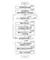
- FIG. 4 and 5 are flowcharts showing an example of registration processing of the identifier 241 and the tire position performed in the tire air pressure detection system 100.
- FIG. In the flowchart of FIG. 3, a processing procedure in the vehicle body side device 1 is shown.
- the control unit 10 of the vehicle body side device 1 causes the transmission unit 13 to transmit measurement start signals all at once from all the transmission antennas 31 to 34 to all the tire side devices 2 (step S101).
- the measurement start signal is a signal for starting measurement of the reception status in the tire side device 2 thereafter.
- the control unit 10 then transmits the measurement signals corresponding to the measurement signals according to a predetermined destination order (for example, right front (FR), right rear (RR), left front (FL), left rear (RL)) after a suitable standby time. Transmission is sequentially performed with a predetermined interval from 31 to 34 (step S102). At this time, the measurement signal is transmitted from each of the transmission antennas 31 to 34 with the same transmission intensity. Moreover, the transmission intensity
- control part 10 judges whether the response signal was received by the receiving antenna 4 from any tire side apparatus 2 after step S102 (step S103).
- step S103 If it is determined in step S103 that a response signal has not been received (S103: NO), the control unit 10 returns the process to step S103 and waits until it is determined that a response signal has been received.
- step S103 If it is determined in step S103 that a response signal has been received (S103: YES), the control unit 10 extracts information on the identifier 241 from the response signal received by the reception unit 14 (step S104). Further, the control unit 10 extracts FLAG data from the response signal (step S105), and stores the correspondence with the FLAG data transmitted together with the identifier 241 in the storage unit 24 (step S106). The control unit 10 determines whether or not a response signal to the measurement signal for all tires T has been received (step S107).
- step S107 If it is determined in step S107 that it has not been received (S107: NO), the control unit 10 returns the process to step S102, selects the next tire T, and executes the process.
- step S107 If it is determined in step S107 that the signal has been received (S107: YES), the control unit 10 sends a reply to the destination of the transmission request stored at the time of occurrence of crosstalk stored in the storage unit 24 and the destination. Reference is made to the correspondence with the identifier 241 of the tire side device 2 that has been made (step S108).
- the control unit 10 determines the destination based on the correspondence between the identifier 241 stored in step S106 and the FLAG data (the number and reception order received), the destination order referred to in step S108, and the correspondence between the returned device identifier 241.
- the correspondence between the order and the identifier 241 corresponding thereto is determined (step S109). The determination method in step S109 will be described in detail later.
- the control unit 10 stores the determined correspondence in the storage unit 24 (step S110), and ends the process.
- the correspondence stored in the storage unit 24 is used in the subsequent air pressure detection process.
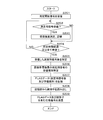
- step S201 when receiving the measurement start signal by the receiving unit 22 (step S201), the control unit 20 determines whether or not the measurement signal is received from any of the transmission antennas 31 to 34 (step S201). Step S202). When it is determined in step S202 that the measurement signal is not received (S202: NO), the control unit 20 advances the process to step S204.
- the control unit 20 measures the received measurement signal by the received intensity measurement unit 25 and stores it in time series (step S203).
- the reception intensity measurement unit 25 measures and continuously outputs the reception intensity of the radio signal received by the reception unit 22, and the control unit 20 acquires the corresponding reception intensity.
- control unit 20 determines whether a predetermined time has elapsed after receiving the measurement start signal, or whether the measurement signals from all the transmission antennas 31 to 34 have been received (step S204). When it is determined that the predetermined time has not elapsed and all the measurement signals have not been received (S204: NO), the control unit 20 returns the process to step S202, for a total of four measurement signals. Until the predetermined time elapses.
- step S204 When it is determined in step S204 that the predetermined time has elapsed or that all the request signals have been received (S204: YES), the control unit 20 is based on the reception strength of each measurement signal stored in time series. Then, the number of received measurement signals is specified (step S205). Further, the control unit 20 specifies the reception order of the measurement signals received with the strongest reception strength (step S206).
- control unit 20 stores the FLAG data including the specified number of measurement signals and the reception order of the strongest signal in the storage unit 24 (step S207).
- the FLAG data may be temporarily stored in the built-in RAM.
- control unit 20 reads the identifier 241 from the storage unit 24 (step S208), and transmits a response signal including the FLAG data and the identifier 241 toward the vehicle body side device 1 (receiving antenna 4) (step S209). The process is terminated.
- the control unit 10 of the vehicle body side device 1 transmits a transmission request to the tire side device 2 of each tire T in the order of the transmission antennas 31, 32, 33, and 34. .
- responses from a plurality of tire-side devices 2 are received, as well as responses from measurement results not only from the right front (FR) but also from the right rear (RR) and left front (FL) tire-side devices 2.
- the control unit 10 recognizes the occurrence of the crosstalk, but stores the identifier 241 and the FLAG data of each tire side device 2 that responds in association with the destination information (for example, FR), and specifies the following procedure. .
- the control unit 10 performs crosstalk on a signal from the transmission antenna 31 provided closest to the right front (FR) tire T in which the destination order is first.
- FLAG data from the tire side device 2 involved in the process is referred to.
- the FLAG data has the following pattern.
- the FLAG data that can be recorded by the tire-side device 2 in each tire T when the signal from the transmitting antenna 31 can be received (the leftmost bar graph is present) and crosstalk occurs is as follows.
- the head of the FLAG data is always “0”. Therefore, when crosstalk occurs with respect to the signal from the transmission antenna 31, if the FLAG data is returned from each tire side device 2 to the signal, the head of the FLAG data is “1” in the vehicle body side device 1. It can be specified that the tire-side device 2 that corresponds to the right front tire T corresponds.
- the FLAG data in the tire side apparatus concerned has the following patterns.
- the FLAG data that can be recorded by the tire side device 2 in each tire T when the signal from the transmitting antenna 32 can be received (the second bar graph from the left exists) and crosstalk occurs is as follows. .
- the end of the FLAG data is always “0”. Therefore, when crosstalk occurs with respect to the signal from the transmission antenna 31, if the FLAG data is responded from each tire side device 2 to the signal, the end of the FLAG data is “1” in the vehicle body side device 1. It can be specified that the tire-side device 2 that corresponds to the left front tire T corresponds.
- the tire-side device 2 of the tire T corresponding to the first transmitting antenna 31 and the tire-side device 2 of the tire T corresponding to the last transmitting antenna 34 are also transmitted from the other tire-side devices 2. Even in a situation where a response is returned, the vehicle body side device 1 can identify each from the FLAG data.
- the FLAG data in the tire side device related to the crosstalk with respect to the signal from the transmission antenna 32 provided closest to the right rear (RR) tire T has the following pattern.
- the FLAG data that can be recorded by the tire side device 2 in each tire T when the signal from the transmitting antenna 32 can be received (the second bar graph from the left exists) and crosstalk occurs is as follows. .
- the FLAG data in the tire side device involved in the crosstalk with respect to the signal from the transmitting antenna 33 provided closest to the left rear (RL) tire T has the following pattern.
- the FLAG data that can be recorded by the tire side device 2 in each tire T when the signal from the transmitting antenna 33 can be received (the second bar graph from the right exists) and crosstalk occurs is as follows. .
- FLAG data “10”, “01”, “100”, “001”, “0100”, and “0010” are arranged in the order if the right front and left front tire side devices 2 can be specified.
- the vehicle body side device 1 can identify the tire side device 2 of the right rear tire T and the tire side device 2 of the left rear tire T. Only when the FLAG data is “010”, it is difficult to specify any of them in the order.
- FIG. 6 that emphasizes the case where the FLAG data is “010” in FIG.
- the distinction can be made as follows. Among the cases where the FLAG data is “010”, the case where crosstalk occurs symmetrically with each other is the case indicated by the codes A and D (in the case of the codes B and C, the above ( 3-1)).
- the vehicle body side device 1 responds to a signal from the transmission antenna 31 and, when the FLAG data is “010”, the tire side of the identifier 241 corresponding to the FLAG data.
- the device 2 can be identified as corresponding to the right rear tire T.
- the tire side device 2 of the identifier 241 corresponding to this FLAG data is the tire T on the left rear. Can be identified.
- the tire T and the tire are matched by the vehicle body side device 1 in accordance with the comparison result of the received intensity without performing comparison with the threshold value stored in advance by the above-described processing.
- the correspondence with the identifier 241 of the side device 2 can be specified.
- the identifier 241 of each tire side device 2 is as follows.
- the crosstalk occurrence status is as follows.
- the identifier 241 of the tire side device 2 responding to the transmitting antenna 31 ⁇ XXX, XXY, XXW The identifier 241 of the tire side device 2 responding to the transmitting antenna 32 ⁇ XXZ, XXW
- the identifier 241 of the tire side device 2 responding to the transmitting antenna 33 ⁇ XXZ, XXW The identifier 241 of the tire side device 2 responding to the transmitting antenna 34 ⁇ XXX, XXY
- the FLAG data described above is updated as follows each time each measurement signal is transmitted.
- the control unit 10 of the vehicle body side device 1 determines the correspondence between the tire position corresponding to the destination order and the identifier 241 from the above information in the following procedure.
- the tire side device 2 With respect to the measurement signal transmitted from the transmitting antenna 31 having the first destination order, the tire side device 2 having the identifier 241 of “XXX, XXY, XXW” responds respectively. A signal is transmitted.
- the FLAG data corresponding to these identifiers 241 are “01”, “10”, and “010”, respectively.
- the control unit 10 stores in advance that the transmission order of the measurement signals from the transmission antenna 31 is “1”.
- the control unit 10 specifies that only “10” is the FLAG data having the strongest reception intensity in the order corresponding to the transmission order “1” of the tire-side device 2 at the right front. Accordingly, in step 109, the control unit 10 determines the correspondence between the destination order “1”, that is, the tire position (FR), and the identifier 241 “XXY” of the FLAG data “10”.
- the control unit 10 can determine the correspondence between the tire position (FL) and the identifier 241 “XXX”. However, if it is determined based on the FLAG data, the FLAG data corresponding to these identifiers 241 are “01” and “10”. The control unit 10 stores in advance that the transmission order of the measurement signals from the transmission antenna 34 corresponding to the left front is “4” th.
- the control unit 10 specifies that “01” is the only FLAG data having the strongest reception intensity in the order corresponding to the transmission order “4” of the tire-side device 2 at the left front. Accordingly, in step 109, the control unit 10 determines the correspondence between the destination order “1”, that is, the tire position (FL), and the identifier 241 “XXX” of the FLAG data “01”.
- the identifier 241 of the tire side device 2 that responds to the signal transmitted from the transmission antenna 31 is “XXX, XXY, XXW”, and does not include “XXXZ”. Therefore, the control unit 10 determines that the tire-side device 2 that has received the measurement signal transmitted most strongly from the transmission antenna 32 having the second transmission order cannot be “XXZ”. At this time, the control unit 10 may determine the correspondence between the destination order “2”, that is, the tire position (RR), and the identifier 241 “XXW” of the FLAG data “010” in Step 109.
- both the first and second transmission antennas 31 and 32, 3 It should also be responsive to the signal from the th or fourth transmit antenna 33,34. Since the tire-side device 2 with the identifier 241 “XXW” responds to the measurement signals from the transmission antennas 31, 32, and 33 and there is no contradiction, the control unit 10 determines that the tire position (RR) and the identifier 241 “ The correspondence with “XXW” can be determined.
- the tire-side device 2 with the identifier 241 of “XXZ, XXW” responds to the measurement signal transmitted from the transmission antenna 33 whose destination order is third. A signal is being transmitted. Since the correspondence between the identifier 241 “XXW” has been determined in the above (3), the control unit 10 can determine the correspondence between the tire position (RL) and the identifier 241 “XXZ”. However, if it is determined based on the FLAG data, the FLAG data corresponding to these identifiers 241 is “01” and “010”, respectively, but the measurement signal transmitted from the third transmission antenna 33 in the transmission order is the strongest.
- the tire side device 2 of “XXW” When receiving and the FLAG data is “010”, the tire side device 2 of “XXW” should have also transmitted a response signal to the measurement signal from the transmission antenna 34 as shown in FIG. It is. However, since the tire side device 2 with the identifier 241 “XXW” does not respond to the measurement signal from the transmission antenna 34 and there is a contradiction, the control unit 10 identifies the identifier 241 “XXW” at the tire position (RL). "Cannot be determined. When the measurement signal transmitted from the third transmission antenna 33 is most strongly received and the FLAG data is “01”, a response signal is sent to the measurement signal transmitted from the fourth transmission antenna 34. Should not have sent.
- the control unit 10 determines that the tire position (RL) and the identifier 241 “XXZ” Can be determined.
- measurement signals are transmitted from the vehicle body side device 1 in a predetermined order, and FLAG data representing the number of reception of measurement signals and the reception order of the strongest signal in the tire side device 2 is the tire side device 2.
- the tire-side device 2 compares the reception strength between the received signals, but creates FLAG data without comparing the reception strength with the set threshold value, and sends it back to the vehicle-side device 1 Good. Since the vehicle body side apparatus 1 knows the destination order of the measurement signals, it is the tire side apparatus 2 corresponding to which destination order by referring to the candidates, that is, the tire side apparatus 2 corresponding to which tire position. Can be identified. Thereby, thereafter, the vehicle body side device 1 can accurately identify each tire T and acquire the measurement result of the air pressure.
- the tire air pressure detection system has been described.
- the vehicle body side device 1 is a BCM unit as described above, the transmission antennas 31 to 34 and the reception antenna 4 are also used in other communication systems. May be.
- the communication system is, for example, a passive entry system.
- the passive entry system includes the vehicle body side device 1 and a portable device related to the passive entry system.
- the vehicle body-side device 1 wirelessly communicates with a portable device held by the user using the transmitting antennas 31 to 34 and / or the receiving antenna 4 to authenticate the portable device and detect the position of the portable device.
- a touch sensor (not shown) is provided on the door handle of the vehicle V.
- a regular portable device is provided. Is located outside the vehicle, the vehicle body side device 1 executes processing such as locking and unlocking the door of the vehicle V.
- the vehicle body side device 1 selects a stronger signal output stage of the transmission antennas 31 to 34 when performing wireless communication with the portable device, and when transmitting a signal to the tire side device 2, the signals of the transmission antennas 31 to 34 are selected.
- the output stage should be selected as low as possible.
- the passive entry system is an example, and the system of the present disclosure can be applied to a system that performs control by performing wireless communication between the vehicle body side device 1 and another wireless communication device.
- the vehicle communication system is configured with a TPMS, a keyless entry system, a smart start (registered trademark) system that enables starting of a prime mover or an air conditioner mounted on the vehicle V without using a mechanical key, and the like. Also good.
Abstract
This tire-side device comprises: a first storage unit that stores an identifier for identifying the tire-side device; a reception intensity measurement unit that measures the reception intensity of each measurement signal; an identification unit that identifies the number of measurement signals which have been received; and a second storage unit that stores the number of measurement signals, which have been received among the measurement signals corresponding to a plurality of tires as sequentially sent to the tire-side devices from a vehicle-side device, and the reception order in which the measurement signal having the strongest reception intensity among the received measurement signals was received. A reply signal, containing information showing the number of the measurement signals and the reception order stored in the second storage unit and the identifier, is sent to the vehicle-side device, and a response is determined by the vehicle-side device on the basis of the comparison of information showing the number of the measurement signals and the reception order sent from the plurality of tire-side devices.
Description
本開示はタイヤ空気圧検出システムに関する。
This disclosure relates to a tire pressure detection system.
車輌に装着された複数のタイヤの空気圧を各検出し、検出された空気圧が異常であった場合に警告等を発するタイヤ空気圧警報システム(TPMS:Tire Pressure Monitoring System )が使用されている。特許文献1は、各タイヤに設けられたセンサを含む検出装置と、該検出装置からの検出信号を受信する車体側の監視装置と、各タイヤの近傍に設けられており、検出装置へLF(Low Frequency )信号を送信する送信機(LFアンテナ)とを含むタイヤ空気圧警報システムを開示している。このような構成のTPMSでは、各送信機から順次対応する検出装置へLF信号が送信され、LF信号を受信した検出装置が監視装置へ向けRF(Radio Frequency )信号で応答し、監視装置がタイヤと検出結果とを対応させる。このとき送信機から送信されるLF信号を、対応する検出装置以外の他のタイヤの検出装置が受信してしまうことでいずれのタイヤの検出装置からの応答信号なのかが不明確となるクロストークの発生が問題になる。特許文献1は特に、クロストーク発生時の対応策として、対応する送信機から受信したときの受信強度のみが閾値よりも大きくなるように閾値を設定しておき、閾値よりも大きい場合のみに応答することが提案されている。同様にして特許文献2は、各検出装置へ対応する送信機から送信したLF信号(トリガ信号)への応答信号に、前記トリガ信号の受信強度が含まれるようにし、応答信号内に含まれる受信強度が所定の範囲内である場合に、前記応答信号に含まれる検出装置のIDを登録する。
Tire pressure warning system (TPMS: TireTPressure Monitoring す る System) that detects the air pressure of multiple tires mounted on the vehicle and issues a warning when the detected air pressure is abnormal is used. Patent Document 1 is provided with a detection device including a sensor provided in each tire, a monitoring device on the vehicle body side that receives a detection signal from the detection device, and in the vicinity of each tire. A tire pressure alarm system is disclosed that includes a transmitter (LF antenna) that transmits a Low (Frequency) signal. In the TPMS having such a configuration, an LF signal is sequentially transmitted from each transmitter to a corresponding detection device, and the detection device that has received the LF signal responds to the monitoring device with an RF (Radio Frequency) signal. And the detection result are made to correspond. At this time, the LF signal transmitted from the transmitter is received by a tire detection device other than the corresponding detection device, so that it is unclear which response signal is received from which tire detection device. The occurrence of is a problem. In Patent Document 1, as a countermeasure against occurrence of crosstalk, a threshold is set so that only the reception intensity when received from the corresponding transmitter is larger than the threshold, and the response is made only when the threshold is larger than the threshold. It has been proposed to do. Similarly, Patent Document 2 discloses that a response signal to an LF signal (trigger signal) transmitted from a transmitter corresponding to each detection device includes the reception intensity of the trigger signal, and is included in the response signal. When the intensity is within a predetermined range, the ID of the detection device included in the response signal is registered.
特許文献1及び2に開示されているシステムでは、受信強度が閾値以上であるか否か、所定の範囲内であるか否かを判断して、対象の検出装置からの応答であるか否かを判断した。しかしながら閾値、又は所定の範囲を設定した場合、車輌が停車している場合にLF信号の不感帯に検出装置の受信機があるときなど、対象の検出装置へのトリガ信号であるにも拘らず受信強度が閾値よりも低いとして応答がされないなど、正確な判断が出来ない可能性がある。更に、車種又は装着されるタイヤの種類等によって閾値は変更されるべきであるが、その種類別の閾値の設定変更は煩雑である。
In the systems disclosed in Patent Documents 1 and 2, it is determined whether or not the reception intensity is equal to or greater than a threshold value and within a predetermined range, and whether or not the response is from a target detection device. Judged. However, when a threshold value or a predetermined range is set, the signal is received regardless of the trigger signal to the target detection device, such as when the receiver is in the dead zone of the LF signal when the vehicle is stopped. There is a possibility that an accurate judgment cannot be made, for example, no response is made if the intensity is lower than the threshold value. Furthermore, the threshold value should be changed depending on the type of vehicle or the type of tire to be mounted, but changing the setting of the threshold value for each type is complicated.
本発明は斯かる事情に鑑みてなされたものであり、タイヤ側での受信強度を用いつつも、その受信強度に対する閾値又は受信強度範囲の設定を行なうことなしに正確に各タイヤを識別して夫々の空気圧を検出することができるタイヤ空気圧検出システム、車体側装置及びタイヤ側装置を提供することを目的とする。
The present invention has been made in view of such circumstances. While using the reception intensity on the tire side, each tire is accurately identified without setting a threshold value or a reception intensity range for the reception intensity. It is an object of the present invention to provide a tire air pressure detection system, a vehicle body side device, and a tire side device that can detect each air pressure.
本開示の一態様に係るタイヤ空気圧検出システムは、車輌に装着されている複数のタイヤ夫々に設けられており、該タイヤの空気圧を検出するセンサ、並びに該センサによる測定結果の送信を要求する信号を無線により受信するタイヤ側受信部、及び前記要求に応じて測定結果を無線により送信するタイヤ側送信部を有するタイヤ側装置と、前記車輌の車体に設けられており、前記車輌の車体に設けられており、前記タイヤ側装置と無線により信号を送受信する車体側送信部及び車体側受信部を有する車体側装置とを含み、該車体側装置にて各タイヤの空気圧を取得し、空気圧の低下を検出するタイヤ空気圧検出システムであって、前記タイヤ側装置は夫々、自装置を識別する識別子を記憶する第1記憶部と、前記測定用信号夫々の受信強度を測定する受信強度測定部と、前記タイヤ側受信部にて受信できた測定用信号数を特定する特定部と、前記車体側装置から前記複数のタイヤに対応するタイヤ側装置宛てに順次送信される測定用信号の内の前記測定用信号数、及び受信できた測定用信号の内の最も受信強度が強い測定用信号を受信した受信順序を記憶する第2記憶部と、該第2記憶部に記憶した測定用信号数及び受信順序を示す情報、及び前記第1記憶部に記憶してある識別子を含む応答信号を車体側装置向けに送信させるタイヤ側送信制御部とを備え、前記車体側装置は、前記複数のタイヤのタイヤ側装置へ前記宛先順序に従い、測定用信号を前記車体側送信部から順次送信させる車体側送信制御部と、前記測定用信号の送信後に前記車体側受信部により応答信号を受信する車体側受信制御部と、複数のタイヤ側装置から送信された前記応答信号夫々に含まれる識別子、並びに測定用信号数及び受信順序を取り出し、比較に基づき前記宛先順序に対応するタイヤ位置と前記識別子とを対応付ける制御部とを備える。
A tire air pressure detection system according to an aspect of the present disclosure is provided in each of a plurality of tires mounted on a vehicle, and a sensor that detects the air pressure of the tire and a signal that requests transmission of a measurement result by the sensor. Is provided on the vehicle body of the vehicle, and is provided on the vehicle body of the vehicle, and is provided on the vehicle body of the vehicle. A vehicle body side device having a vehicle body side transmitter and a vehicle body side receiver for transmitting and receiving signals wirelessly, and acquiring the air pressure of each tire by the vehicle body side device, and reducing the air pressure Tire pressure detection system, wherein each of the tire side devices stores a first storage unit for storing an identifier for identifying the device itself, and reception strength of each of the measurement signals. A receiving intensity measuring unit that measures the number of signals, a specifying unit that specifies the number of measurement signals received by the tire side receiving unit, and a tire side device corresponding to the plurality of tires are sequentially transmitted from the vehicle body side device. A second storage unit that stores the number of measurement signals among the measurement signals to be received and a reception order of receiving the measurement signals having the strongest reception strength among the measurement signals that can be received, and the second storage unit A tire-side transmission control unit that transmits information indicating the number of signals for measurement and the order of reception stored in the first storage unit and a response signal including an identifier stored in the first storage unit to the vehicle-side device, The apparatus includes: a vehicle body side transmission control unit that sequentially transmits measurement signals from the vehicle body side transmission unit to the tire side devices of the plurality of tires according to the destination order; and the vehicle body side reception unit after transmitting the measurement signals. Receive response signal The vehicle body side reception control unit, the identifier included in each of the response signals transmitted from the plurality of tire side devices, the number of signals for measurement and the reception order, and the tire position corresponding to the destination order based on the comparison and the tire position And a control unit that associates the identifier.
本開示の一態様に係る車体側装置は、車輌の車体に設けられており、前記車輌に装着されている複数のタイヤ夫々に設けられているタイヤ側装置と無線信号により情報を送受信する送信部及び受信部を備える車体側装置であって、前記複数のタイヤのタイヤ側装置へ所定の宛先順序に従い、測定用信号を前記送信部から順次送信させる送信制御部と、前記測定用信号の送信後に前記受信部により応答信号を受信する受信制御部と、複数のタイヤ側装置から送信された応答信号に含まれる識別子、並びに測定用信号数及び受信順序を取り出し、取り出した測定用信号数及び受信順序の相互比較に基づき前記所定の宛先順序に対応するタイヤ位置と前記識別子とを対応付ける制御部とを備える。
A vehicle body side device according to an aspect of the present disclosure is provided on a vehicle body of a vehicle, and transmits and receives information with a tire side device provided on each of a plurality of tires attached to the vehicle by radio signals. A transmission control unit that sequentially transmits measurement signals from the transmission unit according to a predetermined destination order to the tire side devices of the plurality of tires, and after transmission of the measurement signals The reception control unit that receives the response signal by the reception unit, the identifier included in the response signal transmitted from the plurality of tire side devices, the number of measurement signals and the reception order are extracted, and the number of measurement signals and the reception order that are extracted And a control unit that associates the tire position corresponding to the predetermined destination order with the identifier based on the mutual comparison.
本開示の一態様に係るタイヤ側装置は、車輌のタイヤに設けられており、前記車輌の車体に設けられている車体側装置と無線信号により情報を送受信する送信部及び受信部を備えるタイヤ側装置であって、自装置を識別する識別子を記憶する第1記憶部と、前記測定用信号夫々の受信強度を測定する受信強度測定部と、前記受信部にて受信した測定用信号数を特定する特定部と、前記車体側装置から該タイヤ側装置宛てに順次送信される測定用信号の内、前記特定された測定用信号数、及び受信できた測定用信号の内の最も受信強度が強い測定用信号を受信した受信順序を記憶する第2記憶部と、該第2記憶部に記憶した測定用信号数及び受信順序を示す情報、及び前記第1記憶部に記憶してある識別子を含む応答信号を車体側装置向けに送信させる送信制御部とを備える。
A tire-side device according to an aspect of the present disclosure is provided on a tire of a vehicle, and includes a transmission unit and a reception unit that transmit and receive information with a vehicle body-side device provided on a vehicle body of the vehicle by radio signals. A first storage unit for storing an identifier for identifying the device itself, a reception intensity measurement unit for measuring the reception intensity of each of the measurement signals, and the number of measurement signals received by the reception unit Among the measurement signals that are sequentially transmitted from the vehicle body side device to the tire side device, the number of the specified measurement signals and the highest received intensity among the measurement signals that can be received A second storage unit for storing the reception order of receiving the measurement signals; information indicating the number of measurement signals and the reception order stored in the second storage unit; and an identifier stored in the first storage unit Response signal for body side equipment And a transmission control unit for signal.
なお本願は、このような特徴的な各構成部を備えるタイヤ空気圧検出システム、並びに該システムを構成する車体側装置及びタイヤ側装置として実現することができるだけでなく、かかる特徴的なステップを含むタイヤ空気圧検出方法として実現したり、かかるステップをコンピュータに実行させるためのプログラムとして実現したりすることができる。また、タイヤ空気圧検出システム、車体側装置、タイヤ側装置の一部又は全部を実現する半導体集積回路として実現したり、タイヤ空気圧検出システム、車体側装置、又はタイヤ側装置を含むその他のシステムとして実現したりすることができる。
The present application can be realized not only as a tire air pressure detection system including such characteristic components, but also as a vehicle body side device and a tire side device constituting the system, and a tire including such characteristic steps. It can be realized as an air pressure detection method, or as a program for causing a computer to execute such steps. Also realized as a semiconductor integrated circuit that realizes part or all of a tire pressure detection system, a vehicle body side device, and a tire side device, or as a tire pressure detection system, a vehicle body side device, or other system including a tire side device. You can do it.
上記によれば、受信強度に対する閾値又は受信強度範囲の設定を行なうことなしに各タイヤのセンサを正確に識別することが可能であり、各タイヤの空気圧を正確に識別して検出することが可能になる。
According to the above, it is possible to accurately identify the sensor of each tire without setting a threshold for the reception intensity or a reception intensity range, and it is possible to accurately identify and detect the air pressure of each tire. become.
[本発明の実施形態の説明]
最初に本開示の実施態様を列記して説明する。また、以下に記載する実施形態の少なくとも一部を任意に組み合わせてもよい。 [Description of Embodiment of the Present Invention]
First, embodiments of the present disclosure will be listed and described. Moreover, you may combine arbitrarily at least one part of embodiment described below.
最初に本開示の実施態様を列記して説明する。また、以下に記載する実施形態の少なくとも一部を任意に組み合わせてもよい。 [Description of Embodiment of the Present Invention]
First, embodiments of the present disclosure will be listed and described. Moreover, you may combine arbitrarily at least one part of embodiment described below.
(1)本開示の一態様に係るタイヤ空気圧検出システムは、車輌に装着されている複数のタイヤ夫々に設けられており、該タイヤの空気圧を検出するセンサ、並びに該センサによる測定結果の送信を要求する信号を無線により受信するタイヤ側受信部、及び前記要求に応じて測定結果を無線により送信するタイヤ側送信部を有するタイヤ側装置と、前記車輌の車体に設けられており、前記車輌の車体に設けられており、前記タイヤ側装置と無線により信号を送受信する車体側送信部及び車体側受信部を有する車体側装置とを含み、該車体側装置にて各タイヤの空気圧を取得し、空気圧の低下を検出するタイヤ空気圧検出システムであって、前記タイヤ側装置は夫々、自装置を識別する識別子を記憶する第1記憶部と、前記測定用信号夫々の受信強度を測定する受信強度測定部と、前記タイヤ側受信部にて受信できた測定用信号数を特定する特定部と、前記車体側装置から前記複数のタイヤに対応するタイヤ側装置宛てに順次送信される測定用信号の内の前記測定用信号数、及び受信できた測定用信号の内の最も受信強度が強い測定用信号を受信した受信順序を記憶する第2記憶部と、該第2記憶部に記憶した測定用信号数及び受信順序を示す情報、及び前記第1記憶部に記憶してある識別子を含む応答信号を車体側装置向けに送信させるタイヤ側送信制御部とを備え、前記車体側装置は、前記複数のタイヤのタイヤ側装置へ前記宛先順序に従い、測定用信号を前記車体側送信部から順次送信させる車体側送信制御部と、前記測定用信号の送信後に前記車体側受信部により応答信号を受信する車体側受信制御部と、複数のタイヤ側装置から送信された前記応答信号夫々に含まれる識別子、並びに測定用信号数及び受信順序を取り出し、比較に基づき前記宛先順序に対応するタイヤ位置と前記識別子とを対応付ける制御部とを備える。
(1) A tire air pressure detection system according to an aspect of the present disclosure is provided in each of a plurality of tires mounted on a vehicle, and a sensor that detects the air pressure of the tire and transmission of a measurement result by the sensor. A tire-side receiving unit that wirelessly receives a request signal; and a tire-side device that includes a tire-side transmitting unit that wirelessly transmits a measurement result in response to the request; and a vehicle body of the vehicle. A vehicle body side device that is provided in a vehicle body and includes a vehicle body side transmission unit and a vehicle body side reception unit that wirelessly transmit and receive signals, and obtains the air pressure of each tire by the vehicle body side device; A tire air pressure detection system for detecting a decrease in air pressure, wherein each of the tire side devices stores a first storage unit that stores an identifier for identifying the device itself, and each of the measurement signals. A reception strength measuring unit that measures signal strength, a specifying unit that specifies the number of measurement signals that can be received by the tire-side receiving unit, and a tire-side device corresponding to the plurality of tires from the vehicle body-side device sequentially A second storage unit for storing the number of measurement signals transmitted among the measurement signals to be transmitted, and the reception order of receiving the measurement signals having the strongest reception intensity among the measurement signals received; A tire-side transmission control unit that transmits information indicating the number of measurement signals stored in the storage unit and the reception order, and a response signal including an identifier stored in the first storage unit to the vehicle body-side device, The vehicle body side device includes a vehicle body side transmission control unit that sequentially transmits measurement signals from the vehicle body side transmission unit according to the destination order to the tire side devices of the plurality of tires, and the vehicle body side reception after the measurement signals are transmitted. Response signal The vehicle body side reception control unit for receiving, the identifier included in each of the response signals transmitted from a plurality of tire side devices, the number of signals for measurement and the reception order are extracted, and the tire position corresponding to the destination order based on the comparison, And a control unit that associates the identifier.
本開示の一態様にあっては、車体側装置から各タイヤ側装置宛てに測定用信号を送信し、タイヤ側装置は、受信できた信号の受信強度を夫々測定し、受信できた信号の測定用信号数と最も受信強度が強かった信号の受信順序を記憶する。タイヤ側装置は夫々、自装置にて記憶した測定用信号数及び受信順序の情報を車体側装置へ応答として自装置を識別する識別子と共に送信する。車体側装置にて各タイヤ側装置から送信された情報を比較して排除法にしたがって各タイヤ側装置が設けられているタイヤのタイヤ位置を判断できる。つまり最も受信強度が強かった信号の前にも測定用信号を受信している場合は、その装置宛ての信号は宛先順序が最初ではなく、逆に受信強度が強かった信号の後にも測定用信号を受信している場合は、その装置宛ての信号は宛先順序が最後ではないと断定できる。
In one aspect of the present disclosure, a measurement signal is transmitted from the vehicle body side device to each tire side device, and the tire side device measures the received intensity of the received signal, and measures the received signal. The number of received signals and the reception order of the signals having the strongest reception strength are stored. Each of the tire side devices transmits the number of measurement signals stored in the own device and information on the reception order together with an identifier for identifying the own device as a response to the vehicle body side device. By comparing the information transmitted from each tire side device by the vehicle body side device, the tire position of the tire provided with each tire side device can be determined according to the exclusion method. In other words, if the signal for measurement is received before the signal with the strongest reception strength, the signal addressed to the device is not in the first destination order, and conversely the signal for measurement after the signal with the strong reception strength. , It can be determined that the signal addressed to the device is not in the last destination order.
(2)本開示の一態様に係るタイヤ空気圧検出システムでは、前記制御部は、前記タイヤ側装置の内のいずれか1つへ測定結果の送信を要求する要求信号を送信した後に複数の応答信号を受信した場合、前記要求信号の要求先に対応するタイヤ位置と前記応答信号に含まれる前記識別子との対応を記憶しておき、前記応答信号に含まれる識別子、並びに測定用信号数及び受信順序と、記憶しておいた前記タイヤ位置と識別子との対応に基づき、前記宛先順序に対応するタイヤ位置と前記識別子とを対応付ける。
(2) In the tire air pressure detection system according to an aspect of the present disclosure, the control unit transmits a plurality of response signals after transmitting a request signal requesting transmission of a measurement result to any one of the tire side devices. Is stored, the correspondence between the tire position corresponding to the request destination of the request signal and the identifier included in the response signal is stored, the identifier included in the response signal, the number of measurement signals, and the reception order Based on the correspondence between the stored tire position and the identifier, the tire position corresponding to the destination order is associated with the identifier.
本開示の一態様にあっては、1つのタイヤ側装置宛てに測定結果を要求したにもかかわらず他のタイヤ側装置からも応答が返ってくるクロストークが発生した場合に、応答してきた各タイヤ側装置の識別子の情報を記憶しておく。車体側装置では、各タイヤ側装置から送信された候補に対し、クロストーク発生時の情報を参照することでより正確に各タイヤ側装置が設けられているタイヤのタイヤ位置を判断できる。
In one aspect of the present disclosure, each response that is made when a crosstalk occurs in which a response is returned from another tire side device even though the measurement result is requested to one tire side device. Information on the identifier of the tire side device is stored. The vehicle body side device can more accurately determine the tire position of the tire in which each tire side device is provided by referring to the information transmitted at the time of occurrence of the crosstalk with respect to the candidate transmitted from each tire side device.
(3)本開示の一態様に係る車体側装置は、車輌の車体に設けられており、前記車輌に装着されている複数のタイヤ夫々に設けられているタイヤ側装置と無線信号により情報を送受信する送信部及び受信部を備える車体側装置であって、前記複数のタイヤのタイヤ側装置へ所定の宛先順序に従い、測定用信号を前記送信部から順次送信させる送信制御部と、前記測定用信号の送信後に前記受信部により応答信号を受信する受信制御部と、複数のタイヤ側装置から送信された応答信号に含まれる識別子、並びに測定用信号数及び受信順序を取り出し、取り出した測定用信号数及び受信順序の相互比較に基づき前記所定の宛先順序に対応するタイヤ位置と前記識別子とを対応付ける制御部とを備える。
(3) A vehicle body side device according to an aspect of the present disclosure is provided in a vehicle body of a vehicle, and transmits / receives information to / from a tire side device provided in each of a plurality of tires attached to the vehicle by radio signals. A vehicle body side device including a transmission unit and a reception unit, wherein the measurement signal is sequentially transmitted from the transmission unit to the tire side device of the plurality of tires according to a predetermined destination order; and the measurement signal The reception control unit that receives the response signal by the receiving unit after transmission of the identifier, the identifier included in the response signal transmitted from the plurality of tire side devices, the number of measurement signals and the order of reception, and the number of measurement signals extracted And a control unit for associating the tire position corresponding to the predetermined destination order with the identifier based on the mutual comparison of the reception order.
本開示の一態様にあっては、上述の(1)と同様に、車体側装置から各タイヤ側装置宛てに測定用信号を送信し、これに対しタイヤ側装置で各々受信できた信号の測定用信号数と最も受信強度が強い信号、即ち自装置宛ての信号の受信順序とが記憶される。車体側装置では各タイヤ側装置にて記憶された測定用信号数及び受信順序の比較から更に排除法にしたがって各タイヤ側装置が設けられているタイヤのタイヤ位置を判断できる。
In one aspect of the present disclosure, as in the above (1), a measurement signal is transmitted from the vehicle body side device to each tire side device, and the signals received by the tire side device can be measured. The number of signals for use and the signal having the strongest reception strength, that is, the reception order of the signals addressed to the own apparatus are stored. The vehicle body side device can further determine the tire position of the tire provided with each tire side device according to the exclusion method from the comparison of the number of signals for measurement stored in each tire side device and the receiving order.
(4)本開示の一態様に係るタイヤ側装置は、車輌のタイヤに設けられており、前記車輌の車体に設けられている車体側装置と無線信号により情報を送受信する送信部及び受信部を備えるタイヤ側装置であって、自装置を識別する識別子を記憶する第1記憶部と、前記測定用信号夫々の受信強度を測定する受信強度測定部と、前記受信部にて受信した測定用信号数を特定する特定部と、前記車体側装置から該タイヤ側装置宛てに順次送信される測定用信号の内、前記特定された測定用信号数、及び受信できた測定用信号の内の最も受信強度が強い測定用信号を受信した受信順序を記憶する第2記憶部と、該第2記憶部に記憶した測定用信号数及び受信順序を示す情報、及び前記第1記憶部に記憶してある識別子を含む応答信号を車体側装置向けに送信させる送信制御部とを備える。
(4) A tire-side device according to an aspect of the present disclosure is provided in a vehicle tire, and includes a transmission unit and a reception unit that transmit and receive information to and from the vehicle-side device provided in the vehicle body by radio signals. A first storage unit that stores an identifier for identifying the own device, a reception intensity measurement unit that measures the reception intensity of each of the measurement signals, and a measurement signal received by the reception unit A specifying unit for specifying the number, and among the measurement signals sequentially transmitted from the vehicle body side device to the tire side device, the number of the specified measurement signals and the most received of the measurement signals received A second storage unit that stores the reception order of receiving the measurement signals having high strength, information indicating the number of measurement signals stored in the second storage unit and the reception order, and the first storage unit Response signal including identifier And a transmission control unit for transmitting to only.
本開示の一態様にあっては、上述の(1)と同様に、タイヤ側装置では、車体側装置から送信された各タイヤ側装置宛ての測定用信号の内、受信できた信号の受信強度を夫々測定し、受信できた信号の数と最も受信強度が強かった信号の受信順序を記憶する。タイヤ側装置では記憶した測定用信号数と最も受信強度が強い信号、即ち自装置宛ての信号の受信順序を応答信号として車体側装置向けに送信する。これを受けて車体側装置にて、これらの情報を比較してタイヤ位置とタイヤ側装置の識別子の対応が決定される。
In one aspect of the present disclosure, as in the above (1), in the tire side device, the reception intensity of the signal that can be received among the measurement signals transmitted from the vehicle body side device to each tire side device. , And the number of signals that can be received and the reception order of the signals having the strongest reception strength are stored. The tire-side device transmits the stored number of measurement signals and the signal having the strongest reception strength, that is, the reception order of the signals addressed to itself to the vehicle-side device as a response signal. In response, the vehicle body side device compares these pieces of information to determine the correspondence between the tire position and the tire side device identifier.
[本開示の実施形態の詳細]
本開示の実施形態に係るタイヤ空気圧検出システムの具体例を、以下に図面を参照しつつ説明する。なお、本発明はこれらの例示に限定されるものではなく、請求の範囲によって示され、請求の範囲と均等の意味及び範囲内でのすべての変更が含まれることが意図される。 [Details of Embodiment of the Present Disclosure]
A specific example of a tire pressure detection system according to an embodiment of the present disclosure will be described below with reference to the drawings. In addition, this invention is not limited to these illustrations, is shown by the claim, and intends that all the changes within the meaning and range equivalent to a claim are included.
図1は、本実施の形態におけるタイヤ空気圧検出システム100の構成部の配置を示す模式図である。本実施の形態のタイヤ空気圧検出システム100は、車体側装置1と、装着されているタイヤTの数に対応する数のタイヤ側装置2とを含む。
FIG. 1 is a schematic diagram showing an arrangement of components of a tire air pressure detection system 100 in the present embodiment. The tire air pressure detection system 100 according to the present embodiment includes a vehicle body side device 1 and a number of tire side devices 2 corresponding to the number of tires T mounted.
車体側装置1は、インストルメントパネル内部又は下部に設置されている。車体側装置1は、各タイヤTのタイヤハウスに設けられた送信アンテナ31~34と信号線により接続されている。
The vehicle body side device 1 is installed inside or below the instrument panel. The vehicle body side device 1 is connected to transmission antennas 31 to 34 provided in a tire house of each tire T by signal lines.
送信アンテナ31は右前のタイヤTに対応する位置、送信アンテナ32は右後のタイヤTに対応する位置、送信アンテナ33は左後のタイヤTに対応する位置、送信アンテナ34は左前のタイヤTに対応する位置に設けられている。送信アンテナ31~34はタイヤ側装置2とへ向けて無線信号を送信するアンテナである。送信アンテナ31~34から送信される信号の搬送波の周波数帯域は例えばLF(Low Frequency )帯(例えば125kHz)を用いる。周波数帯はこれに限られないが、後述の受信アンテナ4とは異なる周波数帯域で、距離による減衰が顕著な周波数帯域を用いるとよい。
The transmission antenna 31 is located at the position corresponding to the right front tire T, the transmission antenna 32 is located at the position corresponding to the right rear tire T, the transmission antenna 33 is located at the position corresponding to the left rear tire T, and the transmission antenna 34 is located at the left front tire T. It is provided at the corresponding position. The transmission antennas 31 to 34 are antennas that transmit radio signals to the tire side device 2. For example, an LF (Low 信号 Frequency) band (for example, 125 kHz) is used as a frequency band of a carrier wave of a signal transmitted from the transmission antennas 31 to 34. The frequency band is not limited to this, but it is preferable to use a frequency band that is different from the receiving antenna 4 described later and that has significant attenuation due to distance.
車体側装置1はまた、車輌Vのルーフに設けられた受信アンテナ4と信号線により接続されている。受信アンテナ4は、例えば車輌Vのルーフの内張り内に設けられている。受信アンテナ4は、タイヤ側装置2から送信される信号を受信する。受信する搬送波の周波数帯域は、RF(Radio Frequency )帯(例えば300MHz、UHF帯)である。周波数帯はこれに限られない。
The vehicle body side device 1 is also connected to a receiving antenna 4 provided on the roof of the vehicle V by a signal line. The receiving antenna 4 is provided in the lining of the roof of the vehicle V, for example. The receiving antenna 4 receives a signal transmitted from the tire side device 2. The frequency band of the received carrier wave is an RF (RadioRadFrequency) band (for example, 300 MHz, UHF band). The frequency band is not limited to this.
タイヤ側装置2は、タイヤのホイール内部夫々に設けられており、例えばダイヤフラム等を用いた圧力センサによって各タイヤの空気圧を測定し、測定結果の空気圧信号を無線により送信するセンサユニットである。
The tire side device 2 is a sensor unit that is provided inside each wheel of the tire and measures the air pressure of each tire by a pressure sensor using a diaphragm, for example, and transmits the air pressure signal of the measurement result wirelessly.
図2は、本実施の形態におけるタイヤ空気圧検出システム100の構成を示すブロック図である。車体側装置1は、車輌Vのドアロックの施錠/開錠の制御、及び車内外灯器類等、ボディ系のアクチュエータの制御を統合的に行なう所謂BCM(Body Control Module )ユニットである。車体側装置1は、制御部10、記憶部11、出力部12、受信部14、及び送信部13を備え、バッテリからの電源供給を受けて動作する。
FIG. 2 is a block diagram showing a configuration of the tire air pressure detection system 100 in the present embodiment. The vehicle body side device 1 is a so-called BCM (Body Control Module) unit that integrally performs control of locking / unlocking of the door lock of the vehicle V and control of body system actuators such as in-vehicle and external lights. The vehicle body side device 1 includes a control unit 10, a storage unit 11, an output unit 12, a reception unit 14, and a transmission unit 13, and operates by receiving power supply from a battery.
制御部10は例えば、1若しくは複数のCPU(Central Processing Unit)又はマルチコアCPUを用い、ROM(Read Only Memory)、RAM(Random Access Memory)、入出力インタフェース、タイマ等を有するマイクロコントローラである。制御部10は、記憶部11に記憶してある制御プログラム1Pに基づき、各構成部を制御する。なお制御プログラム1Pは制御部10の内蔵ROMに記憶してあってもよい。
The control unit 10 is, for example, a microcontroller that uses one or a plurality of CPUs (Central Processing Unit) or a multi-core CPU, and has a ROM (Read Only Memory), a RAM (Random Access Memory), an input / output interface, a timer, and the like. The control unit 10 controls each component based on the control program 1P stored in the storage unit 11. The control program 1P may be stored in a built-in ROM of the control unit 10.
記憶部11は、フラッシュメモリ等の不揮発性メモリを用いる。記憶部11には、制御部10が参照する各種情報が記憶されているほか、上述の制御プログラム1Pが記憶されている。なお記憶部11には、後述するように各タイヤ側装置2から送信される識別子241と、タイヤT各々の識別情報(右前、左前、右後、左後、スペア等のタイヤ位置)との対応が記憶される。記憶部11に記憶されている制御プログラム1Pは、コンピュータが読み取り可能な記録媒体5に記録されている態様でもよい。記憶部11は、図示しない読出装置によって記録媒体5から読み出された制御プログラム5Pを記憶する。記録媒体5はCD(Compact Disc)-ROM、DVD(Digital Versatile Disc)-ROM、BD(Blu-ray (登録商標) Disc )等の光ディスク、フレキシブルディスク、ハードディスク等の磁気ディスク、磁気光ディスク、半導体メモリ等である。また、図示しない通信網に接続されている図示しない外部コンピュータから実施の形態1に係る制御プログラム5Pをダウンロードし、記憶部11に記憶させてもよい。
The storage unit 11 uses a non-volatile memory such as a flash memory. The storage unit 11 stores various types of information referred to by the control unit 10 and the above-described control program 1P. In the storage unit 11, as will be described later, the correspondence between the identifier 241 transmitted from each tire-side device 2 and the identification information of each tire T (the tire positions such as front right, front left, rear right, rear left, spare, etc.) Is memorized. The control program 1P stored in the storage unit 11 may be recorded in the computer-readable recording medium 5. The storage unit 11 stores a control program 5P read from the recording medium 5 by a reading device (not shown). The recording medium 5 is an optical disc such as CD (Compact Disc) -ROM, DVD (Digital Versatile Disc) -ROM, BD (Blu-ray (registered trademark) Disc), a flexible disc, a magnetic disc such as a hard disc, a magnetic optical disc, and a semiconductor memory. Etc. Further, the control program 5P according to the first embodiment may be downloaded from an external computer (not shown) connected to a communication network (not shown) and stored in the storage unit 11.
出力部12は、ディスプレイ61及びスピーカ62が接続されている。ディスプレイ61及びスピーカ62はいずれか一方のみであってもよい。出力部12は制御部10の制御により、ディスプレイ61へ制御信号を出力し、及びスピーカ62へ音声信号を出力する。
The display unit 61 and the speaker 62 are connected to the output unit 12. Only one of the display 61 and the speaker 62 may be provided. The output unit 12 outputs a control signal to the display 61 and outputs an audio signal to the speaker 62 under the control of the control unit 10.
ディスプレイ61は、インストルメントパネル上の速度計を含む計器類のパネル内に設けられた表示灯である。LED(Light Emitting Diode)を用いてもよい。またヘッドアップディスプレイであってもよい。ディスプレイ61は、ナビゲーションシステム等で用いられるタッチパネルを内蔵したタイプであって、LCD(Liquid Crystal Display)又は有機EL(Electro Luminescence)等の表示パネルを用いるものであってもよい。ディスプレイ61は出力部12から出力される信号に基づき、画像又は文字を表示する。
The display 61 is an indicator lamp provided in the instrument panel including the speedometer on the instrument panel. You may use LED (Light * Emitting * Diode). A head-up display may also be used. The display 61 is a type incorporating a touch panel used in a navigation system or the like, and may use a display panel such as an LCD (Liquid Crystal Display) or an organic EL (Electro Luminescence). The display 61 displays an image or a character based on the signal output from the output unit 12.
スピーカ62は、出力部12から出力される信号に基づき、音声又は効果音を発する。
The speaker 62 emits sound or sound effect based on the signal output from the output unit 12.
送信部13は、送信アンテナ31~34と接続されており、該送信アンテナ31~34から送信する信号を変調する変調器を含む送信モジュールを用いる。なお送信部13は内部に切替部13aを有し、該切替部aによって複数の送信アンテナ31~34の内のいずれか一部又は全部を選択して使用することが可能である。また送信部13は、信号出力を選択することが可能な選択部13bを有し、該選択部13bによって各送信アンテナ31~34からの送信強度を複数の出力段階(強弱)からいずれかを選択させることができる。
The transmission unit 13 is connected to transmission antennas 31 to 34, and uses a transmission module including a modulator that modulates signals transmitted from the transmission antennas 31 to 34. The transmission unit 13 has a switching unit 13a therein, and any one or all of the plurality of transmission antennas 31 to 34 can be selected and used by the switching unit a. The transmission unit 13 has a selection unit 13b that can select a signal output, and the selection unit 13b selects the transmission intensity from each of the transmission antennas 31 to 34 from a plurality of output stages (strong and weak). Can be made.
受信部14は、受信アンテナ4と接続されており、該受信アンテナ4にて受信した電波に対する増幅器、フィルター回路、及び復調器を含む受信回路を用いる。
The receiving unit 14 is connected to the receiving antenna 4 and uses a receiving circuit including an amplifier, a filter circuit, and a demodulator for radio waves received by the receiving antenna 4.
タイヤ側装置2は、制御部20、センサ21、送信部23、受信部22、記憶部24及び受信強度測定部25を備える。タイヤ側装置2は、バッテリ又は内蔵電池からの電源供給を受けて動作する。
The tire side device 2 includes a control unit 20, a sensor 21, a transmission unit 23, a reception unit 22, a storage unit 24, and a reception intensity measurement unit 25. The tire side device 2 operates by receiving power supply from a battery or a built-in battery.
制御部20は、例えば1若しくは複数のCPU又はマルチコアCPUを用い、ROM、RAM、入出力インタフェース、タイマ等を有するマイクロコントローラである。制御部20のCPUは入出力インタフェースを介してセンサ21、受信部22、送信部23、及び記憶部24に接続されている。
The control unit 20 is a microcontroller using, for example, one or a plurality of CPUs or a multi-core CPU and having a ROM, a RAM, an input / output interface, a timer, and the like. The CPU of the control unit 20 is connected to the sensor 21, the reception unit 22, the transmission unit 23, and the storage unit 24 via an input / output interface.
センサ21は、例えばダイヤフラムを用い、圧力の大きさによって変化するダイヤフラムの変形量に基づき、タイヤTの空気圧を測定する。センサ21は、測定結果を信号(空気圧に応じた電圧レベルを有する)として制御部20へ出力する。なおセンサ21は更に、温度センサを用いて温度を示す信号を制御部20へ出力する構成としてもよい。
The sensor 21 uses a diaphragm, for example, and measures the air pressure of the tire T based on the amount of deformation of the diaphragm that changes depending on the magnitude of pressure. The sensor 21 outputs the measurement result as a signal (having a voltage level corresponding to the air pressure) to the control unit 20. The sensor 21 may further be configured to output a signal indicating temperature to the control unit 20 using a temperature sensor.
記憶部24は、フラッシュメモリ等の不揮発性メモリである。記憶部24は、制御部20にタイヤ側装置2の各構成部の動作を制御させるため、即ち後述のタイヤ空気圧の測定結果を送受信する処理を実行させるための制御プログラム2Pを記憶している。また記憶部24には、複数のタイヤ側装置2を相互に識別することができるように固有の識別子241が予め記憶されている。なお、図2では制御部20及び記憶部24を夫々別体の構成部として図示しているが、制御部20の内部に記憶部24を備える構成としてもよく、制御プログラム2P及び識別子241は制御部20の内蔵記憶部に記憶されていてもよい。識別子241は例えば夫々(XXX,XXY,XXZ,XXW)であるとする。また記憶部24には、後述にて説明するように、車体側装置1から送信される測定用信号の数及びその内の最強強度の信号の受信順序を示すフラグデータが記憶される(図3参照)。
The storage unit 24 is a nonvolatile memory such as a flash memory. The storage unit 24 stores a control program 2P for causing the control unit 20 to control the operation of each component of the tire-side device 2, that is, for executing processing for transmitting and receiving tire pressure measurement results described later. The storage unit 24 stores in advance a unique identifier 241 so that the plurality of tire-side devices 2 can be identified from each other. In FIG. 2, the control unit 20 and the storage unit 24 are illustrated as separate components. However, the control unit 20 may include the storage unit 24, and the control program 2 </ b> P and the identifier 241 may be controlled. It may be stored in the built-in storage unit of the unit 20. Assume that the identifiers 241 are, for example, (XXX, XXY, XXZ, XXW). Further, as will be described later, the storage unit 24 stores flag data indicating the number of measurement signals transmitted from the vehicle body side device 1 and the reception order of the strongest signal among them (FIG. 3). reference).
受信部22は、アンテナ22aにて受信した複数の無線信号から搬送波の成分を除去して受信信号を抽出し、抽出した受信信号を制御部20へ出力する。本実施の形態では、アンテナ22aが受信する無線信号の搬送波の周波数帯としてLF帯を使用する。アンテナ22aで受信する搬送波の周波数帯は、車体側の送信アンテナ31~34と対応するのであればこの周波数帯に限定されない。
The receiving unit 22 removes a carrier wave component from a plurality of radio signals received by the antenna 22a, extracts the received signal, and outputs the extracted received signal to the control unit 20. In the present embodiment, the LF band is used as the frequency band of the carrier wave of the radio signal received by the antenna 22a. The frequency band of the carrier wave received by the antenna 22a is not limited to this frequency band as long as it corresponds to the transmission antennas 31 to 34 on the vehicle body side.
送信部23は、制御部20により入力される信号を、搬送波を用いて変調し、送信アンテナ23aを通じて無線信号を送信する回路である。本実施の形態では、送信アンテナ23aから送信する信号の搬送波の周波数帯としてRF帯(UHF帯)を使用する。しかしながら送信アンテナ23aで使用する周波数帯は、車体側の受信アンテナ4と対応するのであればこの周波数帯に限定されない。
The transmission unit 23 is a circuit that modulates a signal input from the control unit 20 using a carrier wave and transmits a radio signal through the transmission antenna 23a. In the present embodiment, the RF band (UHF band) is used as the frequency band of the carrier wave of the signal transmitted from the transmission antenna 23a. However, the frequency band used for the transmission antenna 23a is not limited to this frequency band as long as it corresponds to the reception antenna 4 on the vehicle body side.
受信強度測定部25は、増幅回路等を用いてアンテナ22aにて受信した無線信号の受信強度を測定し、制御部20へ出力する。
The reception intensity measurement unit 25 measures the reception intensity of the radio signal received by the antenna 22a using an amplifier circuit or the like, and outputs it to the control unit 20.
このように構成されるタイヤ空気圧検出システム100では、車体側装置1の制御部10が定期的に、各タイヤTの空気圧を取得する。例えば、車体側装置1の制御部10が各タイヤTのタイヤ側装置2へ順次測定結果の送信要求を送信アンテナ31~31からLF信号にて送信する。タイヤ側装置2は自身宛の送信要求を受信した場合にセンサ21で測定して得られた測定結果を記憶部24に記憶してある識別子241と共に送信部23の送信アンテナ23aからRF信号にて送信する。車体側装置1の制御部10は受信アンテナ4を介して受信部14にてRF信号にて応答を受信し、識別子241の情報によっていずれのタイヤTの測定結果であるかを識別する。
In the tire air pressure detection system 100 configured as described above, the control unit 10 of the vehicle body side device 1 periodically acquires the air pressure of each tire T. For example, the control unit 10 of the vehicle body side apparatus 1 sequentially transmits a transmission request for the measurement result to the tire side apparatus 2 of each tire T from the transmission antennas 31 to 31 using an LF signal. When the tire side device 2 receives the transmission request addressed to itself, the tire 21 measures the measurement result obtained by the sensor 21 together with the identifier 241 stored in the storage unit 24 from the transmission antenna 23a of the transmission unit 23 using an RF signal. Send. The control unit 10 of the vehicle body side apparatus 1 receives a response with an RF signal at the reception unit 14 via the reception antenna 4, and identifies which tire T is the measurement result based on the information of the identifier 241.
そして制御部10は各タイヤTの空気圧を取得すると、空気圧低下の閾値と比較し、閾値以下であると判断される場合にはそのタイヤTは空気圧が低下していることを示す警報を出力部12からディスプレイ61又はスピーカ62により出力させる。警報には、空気圧低下が発生しているタイヤTのタイヤ位置を特定する情報が含まれる。ディスプレイ61は例えば、4輪の内のいずれかを示す警告灯を点灯させたり、又は「右前のタイヤの空気圧が低下しています」と文字情報を表示させたりする。スピーカ62は例えばその警告灯と共に効果音を出力したり、又は、「右前のタイヤの空気圧が低下しています」と読み上げの音声を出力したりする。なお比較の際に参照される閾値は車輌V及びタイヤTの種別に応じた閾値であってもよい。このようにして空気圧低下が発生しているタイヤTのメンテナンスの必要性をユーザへ知らしめることができる。なお、空気圧低下は車輌Vの走行制御システムへ通知することにより適切な走行制御を行なうことも可能である。
And when the control part 10 acquires the air pressure of each tire T, it will compare with the threshold value of an air pressure fall, and when it is judged that it is below a threshold value, the alarm which shows that the tire T is reducing the air pressure will be output. 12 is output from the display 61 or the speaker 62. The alarm includes information for specifying the tire position of the tire T in which the air pressure drop has occurred. For example, the display 61 turns on a warning light indicating one of the four wheels, or displays character information such as “the air pressure of the right front tire has decreased”. The speaker 62 outputs, for example, a sound effect together with the warning light, or outputs a voice reading “The air pressure of the right front tire has decreased”. The threshold value referred to in the comparison may be a threshold value corresponding to the type of the vehicle V and the tire T. In this way, it is possible to inform the user of the need for maintenance of the tire T in which a decrease in air pressure has occurred. In addition, it is also possible to perform appropriate traveling control by notifying the traveling control system of the vehicle V of the decrease in air pressure.
このときタイヤ空気圧検出システム100では、タイヤ側装置2から測定結果の信号と共に受信する識別子241が、右前、右後、左後、及び左前(更にスペアが含まれてもよい)のタイヤ位置と対応付けられて記憶部11に記憶(登録)されていることが必要である。タイヤTはホイールごと交換することが可能であるから、タイヤ側装置2とタイヤ位置との関係は固定されないからである。識別子241とタイヤ位置との対応の登録は初期的に(出荷時に)登録されるがそれ以外は、車体側装置1にて、タイヤ側装置2との間にクロストークが発生したことを検知した場合に行なう。クロストークの発生は、例えば車体側装置1の制御部10が右前のタイヤTに対応するタイヤ側装置2宛てに送信アンテナ31から測定値の要求信号を送信させたにも拘わらず、複数のタイヤ側装置2から測定結果が応答信号として送信された場合にこれを検知する。そしてこのとき車体側装置1の制御部10は、送信要求に対して応答してきた複数のタイヤ側装置2に対応する識別子241を、送信要求の宛先を示す情報と共に対応付けて記憶しておく。
At this time, in the tire air pressure detection system 100, the identifier 241 received together with the measurement result signal from the tire side device 2 corresponds to the tire positions of the right front, right rear, left rear, and left front (further, a spare may be included). It is necessary to be attached and stored (registered) in the storage unit 11. This is because the relationship between the tire side device 2 and the tire position is not fixed because the tire T can be replaced with the entire wheel. Registration of the correspondence between the identifier 241 and the tire position is initially registered (at the time of shipment), but other than that, the vehicle body side device 1 detects that crosstalk has occurred with the tire side device 2. If you do. The occurrence of crosstalk is caused by, for example, a case where the control unit 10 of the vehicle body side apparatus 1 transmits a measurement value request signal from the transmission antenna 31 to the tire side apparatus 2 corresponding to the right front tire T. This is detected when the measurement result is transmitted from the side apparatus 2 as a response signal. At this time, the control unit 10 of the vehicle body side device 1 stores the identifiers 241 corresponding to the plurality of tire side devices 2 that have responded to the transmission request in association with information indicating the destination of the transmission request.
なおバッテリからの電源供給を受けている状態で(イグニッションスイッチオン、又はアクセサリオン)、車体側装置1に設けられているリセットボタンの押下を制御部10が検知したときに行なわれてもよい。また制御部10はタイヤTが交換された場合にこれを検知して自動的に行なってもよい。
It may be performed when the control unit 10 detects that the reset button provided in the vehicle body side device 1 is pressed while the power supply from the battery is being received (ignition switch on or accessory on). Moreover, when the tire T is replaced | exchanged, the control part 10 may detect this and may carry out automatically.
また、クロストークが発生した場合に行なわれる識別子241とタイヤ位置との登録処理の説明に先立って、その処理で使用される情報について説明する。図3は、タイヤ側装置2の記憶部24に記憶されてある情報を説明するための説明図である。クロストークは上述したように、宛先のタイヤTに対応するタイヤ側装置2へ向けて送信アンテナ31~34のいずれかから測定値の要求信号を送信させたにも拘わらず、宛先のタイヤT以外のタイヤTに対応するタイヤ側装置2へも要求信号が到達し、測定結果が応答信号として送信される現象である。そこでタイヤ側装置2にて、車体側装置1からの他装置宛てへの信号の受信状況を測定させる。図3は、車体側装置1から所定の順序で特定の信号(測定用信号)を送信した場合の各タイヤ側装置2における受信状況を示している。特定の信号は、右前(FR)の送信アンテナ31から右後(RR)、左後(RL)、左前(FL)の順で送信されることとする。そして各タイヤ側装置2の受信部22にてこれらの信号の受信状況を一覧とすると図3のようになる。
Also, prior to the description of the registration process of the identifier 241 and the tire position performed when crosstalk occurs, information used in the process will be described. FIG. 3 is an explanatory diagram for explaining information stored in the storage unit 24 of the tire-side device 2. As described above, the crosstalk is not the destination tire T, although the measurement value request signal is transmitted from any of the transmission antennas 31 to 34 to the tire side device 2 corresponding to the destination tire T. This is a phenomenon in which the request signal reaches the tire side device 2 corresponding to the tire T and the measurement result is transmitted as a response signal. Therefore, the tire side device 2 measures the reception status of signals from the vehicle body side device 1 to other devices. FIG. 3 shows a reception situation in each tire side device 2 when a specific signal (measurement signal) is transmitted from the vehicle body side device 1 in a predetermined order. It is assumed that the specific signal is transmitted from the right front (FR) transmission antenna 31 in the order of rear right (RR), rear left (RL), and front left (FL). The reception status of these signals is listed in the receiving unit 22 of each tire side device 2 as shown in FIG.
例えば図3において、右前のタイヤTのタイヤ側装置2の受信部22にて、車体側装置1から順次送信される特定の信号を2つのみ受信できる場合、その組み合わせは、直近の右前のタイヤT(FR)の送信アンテナ31から送信される信号と、他のいずれかから送信される信号である。この場合、右前のタイヤT(FR)の送信アンテナ31から送信される信号は必ず最初に受信でき、しかもその受信強度は最も強いはずである。制御部20は、受信できた信号の数及びその内の最強の受信強度の信号の順序に対応するFLAGデータを記憶する。図3の例では、右前のタイヤTのタイヤ側装置2の記憶部24にはFLAGデータとして「10」が記憶される。なおFLAGデータは詳細には、受信できた信号の数を示す4ビットの情報及び受信強度の順序に対応する4ビットの情報より構成されてもよいし、信号の数を示さず16ビット(2バイト)で4ビットずつ「1」又は「0」を表わしてもよい。前者の場合、2つのみ受信して最初の受信信号強度が最強である場合は、00101000(b)(=0x28)と記憶され、後者の場合、2つのみ受信して最初の受信信号強度が最強である場合は16進数で(0x10ff)と記憶されるようにしてもよい。
For example, in FIG. 3, when only two specific signals sequentially transmitted from the vehicle body side device 1 can be received by the receiving unit 22 of the tire side device 2 of the right front tire T, the combination is the nearest right front tire. A signal transmitted from the T (FR) transmission antenna 31 and a signal transmitted from any other. In this case, the signal transmitted from the transmission antenna 31 of the right front tire T (FR) can always be received first, and the reception intensity should be the strongest. The control unit 20 stores FLAG data corresponding to the number of signals that can be received and the order of the signals having the strongest reception strength. In the example of FIG. 3, “10” is stored as FLAG data in the storage unit 24 of the tire side device 2 of the right front tire T. In detail, the FLAG data may be composed of 4-bit information indicating the number of signals that can be received and 4-bit information corresponding to the order of the reception intensity, or 16 bits (2 Byte) may represent “1” or “0” by 4 bits. In the former case, when only two are received and the initial received signal strength is the strongest, 00101000 (b) (= 0x28) is stored, and in the latter case, only two are received and the initial received signal strength is If it is the strongest, it may be stored as (0x10ff) in hexadecimal.
右前のタイヤTのタイヤ側装置2の受信部22にて、送信アンテナ31~34から送信された特定の信号の内の3つを受信できる場合、その組み合わせは、右前のタイヤT(FR)の送信アンテナ31から送信される信号と、他のいずれかから送信される信号である。この場合、右前のタイヤT(FR)の送信アンテナ31から送信される信号は必ず最初に受信でき、しかもその受信強度は最も強いはずである。したがってこの場合、FLAGデータはいずれも「100」が記憶される。送信アンテナ31~34から送信された特定の信号の内、全てを受信できる場合は右前のタイヤT(FR)の送信アンテナ31から送信される信号を最初に受信し、更にその受信強度は最も強い。この場合、FLAGデータはいずれも「1000」が記憶される。
When the reception unit 22 of the tire side device 2 of the right front tire T can receive three of the specific signals transmitted from the transmission antennas 31 to 34, the combination of the right front tire T (FR) A signal transmitted from the transmission antenna 31 and a signal transmitted from any other. In this case, the signal transmitted from the transmission antenna 31 of the right front tire T (FR) can always be received first, and the reception intensity should be the strongest. Therefore, in this case, “100” is stored for all FLAG data. When all of the specific signals transmitted from the transmitting antennas 31 to 34 can be received, the signal transmitted from the transmitting antenna 31 of the right front tire T (FR) is received first, and the reception strength is the strongest. . In this case, “1000” is stored for all FLAG data.
同様にして、右後のタイヤTのタイヤ側装置2の受信部22にて、車体側装置1から順次送信される特定の信号を2つのみ受信できる場合、その組み合わせは、直近の右後のタイヤT(RR)の送信アンテナ32から送信される信号と、他のいずれかから送信される信号である。この場合、右後のタイヤT(RR)の送信アンテナ32から送信される信号が受信できる順序は最初のときと、2番目のときとがある。右後のタイヤT(RR)の送信アンテナ32から送信される信号は最も強い受信強度で受信できるが、その受信順序は定まらない。送信アンテナ31~34から送信された特定の信号の内の3つを受信できる場合、その組み合わせは、直近の右後のタイヤT(RR)の送信アンテナ32から送信される信号と、他のいずれかから送信される信号である。送信アンテナ32から送信される信号を最も強く受信できるが、図3に示すようにその受信順序は3番目とはならないが、1番目と2番目とで定まらない。
Similarly, when only two specific signals sequentially transmitted from the vehicle body side device 1 can be received by the receiving unit 22 of the tire side device 2 of the right rear tire T, the combination of the right rear tire A signal transmitted from the transmission antenna 32 of the tire T (RR) and a signal transmitted from any other. In this case, the order in which the signals transmitted from the transmission antenna 32 of the right rear tire T (RR) can be received is the first and second. A signal transmitted from the transmission antenna 32 of the right rear tire T (RR) can be received with the strongest reception strength, but the reception order is not determined. When three of the specific signals transmitted from the transmitting antennas 31 to 34 can be received, the combination is the signal transmitted from the transmitting antenna 32 of the latest right rear tire T (RR) and any other signal. It is a signal transmitted from Although the signal transmitted from the transmitting antenna 32 can be received most strongly, the receiving order is not the third as shown in FIG. 3, but the first and second are not determined.
このようにして、可能性のある受信状況をまとめると、受信できた数と、最も強く受信できた信号の順序から、その最も強く受信した信号の宛先順序の候補が絞り込める。
In this way, when the possible reception situations are summarized, candidates for the destination order of the strongest received signal can be narrowed down from the number of received signals and the order of the signals that have been received most strongly.
そこで各タイヤ側装置2の制御部20は、特定の信号(測定用信号)を受信する都度、図3に示したようなFLAGデータを記憶部24に記憶し、夫々測定用信号の応答信号としてFLAGデータを車体側装置1へ向けて送信する。
Therefore, each time a specific signal (measurement signal) is received, the control unit 20 of each tire-side device 2 stores the FLAG data as shown in FIG. 3 in the storage unit 24, and each response signal is a measurement signal response signal. FLAG data is transmitted to the vehicle body side device 1.
図4及び図5は、タイヤ空気圧検出システム100にて行なわれる識別子241とタイヤ位置との登録処理の一例を示すフローチャートである。図3のフローチャートでは、車体側装置1における処理手順を示す。車体側装置1の制御部10は第1に、送信部13によって全送信アンテナ31~34から、全てのタイヤ側装置2へ向けて一斉に測定開始信号を送信させる(ステップS101)。測定開始信号は、以後、タイヤ側装置2における受信状況の測定を開始させるための信号である。
4 and 5 are flowcharts showing an example of registration processing of the identifier 241 and the tire position performed in the tire air pressure detection system 100. FIG. In the flowchart of FIG. 3, a processing procedure in the vehicle body side device 1 is shown. First, the control unit 10 of the vehicle body side device 1 causes the transmission unit 13 to transmit measurement start signals all at once from all the transmission antennas 31 to 34 to all the tire side devices 2 (step S101). The measurement start signal is a signal for starting measurement of the reception status in the tire side device 2 thereafter.
制御部10はその後適切な待機時間後に、測定用信号を所定の宛先順序(例えば右前(FR)、右後(RR)、左前(FL)、左後(RL)の順)に従って対応する送信アンテナ31~34から所定の間隔を開けて順次送信する(ステップS102)。なおこのとき測定用信号は、各送信アンテナ31~34から同一の送信強度で送信される。またその送信強度は、タイヤハウスから他のタイヤハウスの内の少なくとも1つのタイヤハウスに装着されているタイヤTのホイール内部まで届く範囲とするとよい。
The control unit 10 then transmits the measurement signals corresponding to the measurement signals according to a predetermined destination order (for example, right front (FR), right rear (RR), left front (FL), left rear (RL)) after a suitable standby time. Transmission is sequentially performed with a predetermined interval from 31 to 34 (step S102). At this time, the measurement signal is transmitted from each of the transmission antennas 31 to 34 with the same transmission intensity. Moreover, the transmission intensity | strength is good to be the range which reaches the inside of the wheel of the tire T with which at least 1 tire house is mounted | worn from a tire house.
そして制御部10は、ステップS102の後、いずれかのタイヤ側装置2から応答信号を受信アンテナ4にて受信したか否かを判断する(ステップS103)。
And the control part 10 judges whether the response signal was received by the receiving antenna 4 from any tire side apparatus 2 after step S102 (step S103).
ステップS103にて応答信号を受信していないと判断された場合(S103:NO)、制御部10は処理をステップS103へ戻し、応答信号を受信したと判断されるまで待機する。
If it is determined in step S103 that a response signal has not been received (S103: NO), the control unit 10 returns the process to step S103 and waits until it is determined that a response signal has been received.
ステップS103にて応答信号を受信したと判断された場合(S103:YES)、制御部10は受信部14にて受信した応答信号から識別子241の情報を取り出す(ステップS104)。更に制御部10は、応答信号からFLAGデータを取り出し(ステップS105)、識別子241と共に送信されたFLAGデータとの対応を記憶部24に記憶する(ステップS106)。制御部10は、全タイヤTに向けての測定用信号に対する応答信号を受信したか否かを判断する(ステップS107)。
If it is determined in step S103 that a response signal has been received (S103: YES), the control unit 10 extracts information on the identifier 241 from the response signal received by the reception unit 14 (step S104). Further, the control unit 10 extracts FLAG data from the response signal (step S105), and stores the correspondence with the FLAG data transmitted together with the identifier 241 in the storage unit 24 (step S106). The control unit 10 determines whether or not a response signal to the measurement signal for all tires T has been received (step S107).
ステップS107にて受信していないと判断された場合(S107:NO)、制御部10は処理をステップS102へ戻し、次のタイヤTを選択して処理を実行する。
If it is determined in step S107 that it has not been received (S107: NO), the control unit 10 returns the process to step S102, selects the next tire T, and executes the process.
またステップS107にて受信したと判断された場合(S107:YES)、制御部10は、予め記憶部24に記憶しておいたクロストーク発生時における送信要求の宛先とその宛先に対して返信をしてきたタイヤ側装置2の識別子241との対応を参照する(ステップS108)。制御部10は、ステップS106で記憶した識別子241とFLAGデータ(受信した数及び受信順序)との対応と、ステップS108で参照した宛先順序と返信してきた装置の識別子241の対応とに基づき、宛先順序とこれに対応する識別子241との対応を決定する(ステップS109)。ステップS109の決定方法については後述にて詳細を説明する。制御部10は、決定した対応を記憶部24に記憶し(ステップS110)、処理を終了する。記憶部24に記憶した対応は、以後の空気圧検出処理で用いられる。
If it is determined in step S107 that the signal has been received (S107: YES), the control unit 10 sends a reply to the destination of the transmission request stored at the time of occurrence of crosstalk stored in the storage unit 24 and the destination. Reference is made to the correspondence with the identifier 241 of the tire side device 2 that has been made (step S108). The control unit 10 determines the destination based on the correspondence between the identifier 241 stored in step S106 and the FLAG data (the number and reception order received), the destination order referred to in step S108, and the correspondence between the returned device identifier 241. The correspondence between the order and the identifier 241 corresponding thereto is determined (step S109). The determination method in step S109 will be described in detail later. The control unit 10 stores the determined correspondence in the storage unit 24 (step S110), and ends the process. The correspondence stored in the storage unit 24 is used in the subsequent air pressure detection process.
図5のフローチャートでは、タイヤ側装置2における処理手順の一例を示す。タイヤ側装置2側において制御部20は、受信部22により測定開始信号を受信すると(ステップS201)、送信アンテナ31~34の内のいずれかから測定用信号を受信したか否かを判断する(ステップS202)。ステップS202にて測定用信号を受信しないと判断された場合(S202:NO)、制御部20は処理をステップS204へ処理を進める。
In the flowchart of FIG. 5, an example of a processing procedure in the tire side device 2 is shown. On the tire side device 2 side, when receiving the measurement start signal by the receiving unit 22 (step S201), the control unit 20 determines whether or not the measurement signal is received from any of the transmission antennas 31 to 34 (step S201). Step S202). When it is determined in step S202 that the measurement signal is not received (S202: NO), the control unit 20 advances the process to step S204.
ステップS202にて測定用信号を受信したと判断された場合(S202:YES)、制御部20は受信した測定用信号の受信強度測定部25により測定し、時系列に記憶する(ステップS203)。なお受信強度測定部25は受信部22において受信できた無線信号の受信強度を測定して継続して出力しており、制御部20は対応する受信強度を取得する。
When it is determined that the measurement signal is received in step S202 (S202: YES), the control unit 20 measures the received measurement signal by the received intensity measurement unit 25 and stores it in time series (step S203). The reception intensity measurement unit 25 measures and continuously outputs the reception intensity of the radio signal received by the reception unit 22, and the control unit 20 acquires the corresponding reception intensity.
制御部20は次に、測定開始信号を受信してから所定時間が経過したか、又は送信アンテナ31~34全てからの測定用信号を受信したか否かを判断する(ステップS204)。所定時間が経過しておらず、また、全ての測定用信号を受信していないと判断された場合(S204:NO)、制御部20は処理をステップS202へ戻し、計4回の測定用信号を受信するか、所定時間が経過するまで処理を繰り返す。
Next, the control unit 20 determines whether a predetermined time has elapsed after receiving the measurement start signal, or whether the measurement signals from all the transmission antennas 31 to 34 have been received (step S204). When it is determined that the predetermined time has not elapsed and all the measurement signals have not been received (S204: NO), the control unit 20 returns the process to step S202, for a total of four measurement signals. Until the predetermined time elapses.
ステップS204にて所定時間が経過したか、又は全ての要求信号を受信したと判断された場合(S204:YES)、制御部20は時系列に記憶してある各測定用信号の受信強度に基づき、受信した測定用信号の数を特定する(ステップS205)。そして更に制御部20は、最強の受信強度で受信した測定用信号の受信順序を特定する(ステップS206)。
When it is determined in step S204 that the predetermined time has elapsed or that all the request signals have been received (S204: YES), the control unit 20 is based on the reception strength of each measurement signal stored in time series. Then, the number of received measurement signals is specified (step S205). Further, the control unit 20 specifies the reception order of the measurement signals received with the strongest reception strength (step S206).
そして制御部20は、特定した測定用信号数及び最強強度信号の受信順序を含むFLAGデータを記憶部24に記憶する(ステップS207)。なおFLAGデータは内蔵RAMに一時的に記憶されるようにしてもよい。
Then, the control unit 20 stores the FLAG data including the specified number of measurement signals and the reception order of the strongest signal in the storage unit 24 (step S207). The FLAG data may be temporarily stored in the built-in RAM.
次に制御部20は、記憶部24から識別子241を読み出しておき(ステップS208)、FLAGデータと識別子241を含む応答信号を車体側装置1(受信アンテナ4)へ向けて送信し(ステップS209)、処理を終了する。
Next, the control unit 20 reads the identifier 241 from the storage unit 24 (step S208), and transmits a response signal including the FLAG data and the identifier 241 toward the vehicle body side device 1 (receiving antenna 4) (step S209). The process is terminated.
上述のステップS109におけるFLAGデータに基づく識別子と宛先との対応の決定処理手順を説明する。まず車体側装置1の制御部10は、タイヤTの空気圧の測定結果を取得するに際し、送信アンテナ31,32,33,34の順で各タイヤTのタイヤ側装置2宛てに送信要求を送信する。このときに複数のタイヤ側装置2からの応答を受信右前(FR)のみならず右後(RR)、左前(FL)のタイヤ側装置2からも測定結果の応答を受信する。制御部10はこの場合、クロストーク発生を認識するが、宛先の情報(例えばFR)に対応付けて応答してきた各タイヤ側装置2の識別子241及びFLAGデータを記憶し、以下の手順で特定する。
The determination processing procedure for the correspondence between the identifier and the destination based on the FLAG data in step S109 described above will be described. First, when acquiring the measurement result of the air pressure of the tire T, the control unit 10 of the vehicle body side device 1 transmits a transmission request to the tire side device 2 of each tire T in the order of the transmission antennas 31, 32, 33, and 34. . At this time, responses from a plurality of tire-side devices 2 are received, as well as responses from measurement results not only from the right front (FR) but also from the right rear (RR) and left front (FL) tire-side devices 2. In this case, the control unit 10 recognizes the occurrence of the crosstalk, but stores the identifier 241 and the FLAG data of each tire side device 2 that responds in association with the destination information (for example, FR), and specifies the following procedure. .
クロストークの全ての状況は図3に示したようになる。送信アンテナ31~34の夫々について以下のように検討する。
The whole situation of crosstalk is as shown in Fig.3. Each of the transmission antennas 31 to 34 is examined as follows.
1:宛先順序が最初の送信アンテナ31に対応するタイヤTについて
まず制御部10は宛先順序が最初である右前(FR)のタイヤTの最も近くに設けられた送信アンテナ31からの信号に対するクロストークに関与するタイヤ側装置2からのFLAGデータを参照する。FLAGデータは以下のパターンがある。送信アンテナ31からの信号を受信できて(最も左寄りの棒グラフが存在する)且つクロストークが発生しているときの各タイヤT内のタイヤ側装置2で記録され得るFLAGデータは以下である。
右前(FR):「10」、「100」又は「1000」
右後(RR):「01」、「010」又は「0100」
左後(RL):「01」、「001」、「010」又は「0010」
左前(FL):「01」、「001」又は「0001」 1: Regarding Tire T Corresponding toFirst Transmission Antenna 31 in Destination Order First, the control unit 10 performs crosstalk on a signal from the transmission antenna 31 provided closest to the right front (FR) tire T in which the destination order is first. FLAG data from the tire side device 2 involved in the process is referred to. The FLAG data has the following pattern. The FLAG data that can be recorded by the tire-side device 2 in each tire T when the signal from the transmitting antenna 31 can be received (the leftmost bar graph is present) and crosstalk occurs is as follows.
Front right (FR): “10”, “100” or “1000”
Rear right (RR): “01”, “010” or “0100”
Left rear (RL): “01”, “001”, “010” or “0010”
Front left (FL): “01”, “001” or “0001”
まず制御部10は宛先順序が最初である右前(FR)のタイヤTの最も近くに設けられた送信アンテナ31からの信号に対するクロストークに関与するタイヤ側装置2からのFLAGデータを参照する。FLAGデータは以下のパターンがある。送信アンテナ31からの信号を受信できて(最も左寄りの棒グラフが存在する)且つクロストークが発生しているときの各タイヤT内のタイヤ側装置2で記録され得るFLAGデータは以下である。
右前(FR):「10」、「100」又は「1000」
右後(RR):「01」、「010」又は「0100」
左後(RL):「01」、「001」、「010」又は「0010」
左前(FL):「01」、「001」又は「0001」 1: Regarding Tire T Corresponding to
Front right (FR): “10”, “100” or “1000”
Rear right (RR): “01”, “010” or “0100”
Left rear (RL): “01”, “001”, “010” or “0010”
Front left (FL): “01”, “001” or “0001”
ここで、送信アンテナ31からの信号に応答すべきタイヤ側装置2以外では、FLAGデータの先頭は必ず「0」である。このことから送信アンテナ31からの信号に対してクロストークが発生した場合、該信号に対して各タイヤ側装置2からFLAGデータを応答させれば、車体側装置1ではFLAGデータの先頭が「1」であるタイヤ側装置2が右前のタイヤTに対応すると特定することができる。
Here, except for the tire side device 2 that should respond to the signal from the transmitting antenna 31, the head of the FLAG data is always “0”. Therefore, when crosstalk occurs with respect to the signal from the transmission antenna 31, if the FLAG data is returned from each tire side device 2 to the signal, the head of the FLAG data is “1” in the vehicle body side device 1. It can be specified that the tire-side device 2 that corresponds to the right front tire T corresponds.
2:宛先順序が最後の送信アンテナ34に対応するタイヤTについて
同様にして、宛先順序が最後である左前(FL)のタイヤTの最も近くに設けられた送信アンテナ34からの信号に対するクロストークに関与するタイヤ側装置でのFLAGデータは以下のパターンがある。送信アンテナ32からの信号を受信できて(左から2番目の棒グラフが存在する)且つクロストークが発生しているときの各タイヤT内のタイヤ側装置2で記録され得るFLAGデータは以下である。
右前(FR):「10」、「100」又は「1000」
右後(RR):「10」、「010」、「100」又は「0100」
左後(RL):「10」、「010」又は「0010」
左前(FL):「01」、「001」又は「0001」 2: For the tire T corresponding to the last transmittingantenna 34 in the destination order Similarly, in the case of the crosstalk for the signal from the transmitting antenna 34 provided closest to the front left (FL) tire T whose destination order is the last. The FLAG data in the tire side apparatus concerned has the following patterns. The FLAG data that can be recorded by the tire side device 2 in each tire T when the signal from the transmitting antenna 32 can be received (the second bar graph from the left exists) and crosstalk occurs is as follows. .
Front right (FR): “10”, “100” or “1000”
Rear right (RR): “10”, “010”, “100” or “0100”
Left rear (RL): “10”, “010” or “0010”
Front left (FL): “01”, “001” or “0001”
同様にして、宛先順序が最後である左前(FL)のタイヤTの最も近くに設けられた送信アンテナ34からの信号に対するクロストークに関与するタイヤ側装置でのFLAGデータは以下のパターンがある。送信アンテナ32からの信号を受信できて(左から2番目の棒グラフが存在する)且つクロストークが発生しているときの各タイヤT内のタイヤ側装置2で記録され得るFLAGデータは以下である。
右前(FR):「10」、「100」又は「1000」
右後(RR):「10」、「010」、「100」又は「0100」
左後(RL):「10」、「010」又は「0010」
左前(FL):「01」、「001」又は「0001」 2: For the tire T corresponding to the last transmitting
Front right (FR): “10”, “100” or “1000”
Rear right (RR): “10”, “010”, “100” or “0100”
Left rear (RL): “10”, “010” or “0010”
Front left (FL): “01”, “001” or “0001”
ここで、送信アンテナ34からの信号に応答すべきタイヤ側装置2以外では、FLAGデータの末尾は必ず「0」である。このことから送信アンテナ31からの信号に対してクロストークが発生した場合、該信号に対して各タイヤ側装置2からFLAGデータを応答させれば、車体側装置1ではFLAGデータの末尾が「1」であるタイヤ側装置2が左前のタイヤTに対応すると特定することができる。
Here, except for the tire side device 2 that should respond to the signal from the transmission antenna 34, the end of the FLAG data is always “0”. Therefore, when crosstalk occurs with respect to the signal from the transmission antenna 31, if the FLAG data is responded from each tire side device 2 to the signal, the end of the FLAG data is “1” in the vehicle body side device 1. It can be specified that the tire-side device 2 that corresponds to the left front tire T corresponds.
このように送信順序が最初の送信アンテナ31に対応するタイヤTのタイヤ側装置2と、最後の送信アンテナ34に対応するタイヤTのタイヤ側装置2とについては、他のタイヤ側装置2からも応答が返ってくる状況でも、車体側装置1にてFLAGデータから各々を特定することができる。
As described above, the tire-side device 2 of the tire T corresponding to the first transmitting antenna 31 and the tire-side device 2 of the tire T corresponding to the last transmitting antenna 34 are also transmitted from the other tire-side devices 2. Even in a situation where a response is returned, the vehicle body side device 1 can identify each from the FLAG data.
3:送信アンテナ32,33に対応するタイヤTについて
送信順序が2番目の送信アンテナ32に対応するタイヤTのタイヤ側装置2、及び3番目の送信アンテナ33に対応するタイヤTのタイヤ側装置2については以下のようにして各々を区別することができる。 3: About the tire T corresponding to the transmission antennas 32 and 33 The tire side apparatus 2 of the tire T corresponding to the transmission antenna 32 with the second transmission order, and the tire side apparatus 2 of the tire T corresponding to the third transmission antenna 33 Each can be distinguished as follows.
送信順序が2番目の送信アンテナ32に対応するタイヤTのタイヤ側装置2、及び3番目の送信アンテナ33に対応するタイヤTのタイヤ側装置2については以下のようにして各々を区別することができる。 3: About the tire T corresponding to the
右後(RR)のタイヤTの最も近くに設けられた送信アンテナ32からの信号に対するクロストークに関与するタイヤ側装置でのFLAGデータは以下のパターンがある。送信アンテナ32からの信号を受信できて(左から2番目の棒グラフが存在する)且つクロストークが発生しているときの各タイヤT内のタイヤ側装置2で記録され得るFLAGデータは以下である。
右前(FR):「10」、「100」又は「1000」
右後(RR):「01」、「10」、「010」、「100」又は「0100」
左後(RL):「01」、「001」、「010」又は「0010」
左前(FL):「01」、「001」又は「0001」 The FLAG data in the tire side device related to the crosstalk with respect to the signal from thetransmission antenna 32 provided closest to the right rear (RR) tire T has the following pattern. The FLAG data that can be recorded by the tire side device 2 in each tire T when the signal from the transmitting antenna 32 can be received (the second bar graph from the left exists) and crosstalk occurs is as follows. .
Front right (FR): “10”, “100” or “1000”
Rear right (RR): “01”, “10”, “010”, “100” or “0100”
Left rear (RL): “01”, “001”, “010” or “0010”
Front left (FL): “01”, “001” or “0001”
右前(FR):「10」、「100」又は「1000」
右後(RR):「01」、「10」、「010」、「100」又は「0100」
左後(RL):「01」、「001」、「010」又は「0010」
左前(FL):「01」、「001」又は「0001」 The FLAG data in the tire side device related to the crosstalk with respect to the signal from the
Front right (FR): “10”, “100” or “1000”
Rear right (RR): “01”, “10”, “010”, “100” or “0100”
Left rear (RL): “01”, “001”, “010” or “0010”
Front left (FL): “01”, “001” or “0001”
同様にして左後(RL)のタイヤTの最も近くに設けられた送信アンテナ33からの信号に対するクロストークに関与するタイヤ側装置でのFLAGデータは以下のパターンがある。送信アンテナ33からの信号を受信できて(右から2番目の棒グラフが存在する)且つクロストークが発生しているときの各タイヤT内のタイヤ側装置2で記録され得るFLAGデータは以下である。
右前(FR):「10」、「100」又は「1000」
右後(RR):「10」、「010」、「100」又は「0100」
左後(RL):「01」、「10」、「001」、「010」又は「0010」
左前(FL):「01」、「001」又は「0001」 Similarly, the FLAG data in the tire side device involved in the crosstalk with respect to the signal from the transmittingantenna 33 provided closest to the left rear (RL) tire T has the following pattern. The FLAG data that can be recorded by the tire side device 2 in each tire T when the signal from the transmitting antenna 33 can be received (the second bar graph from the right exists) and crosstalk occurs is as follows. .
Front right (FR): “10”, “100” or “1000”
Rear right (RR): “10”, “010”, “100” or “0100”
Left rear (RL): “01”, “10”, “001”, “010” or “0010”
Front left (FL): “01”, “001” or “0001”
右前(FR):「10」、「100」又は「1000」
右後(RR):「10」、「010」、「100」又は「0100」
左後(RL):「01」、「10」、「001」、「010」又は「0010」
左前(FL):「01」、「001」又は「0001」 Similarly, the FLAG data in the tire side device involved in the crosstalk with respect to the signal from the transmitting
Front right (FR): “10”, “100” or “1000”
Rear right (RR): “10”, “010”, “100” or “0100”
Left rear (RL): “01”, “10”, “001”, “010” or “0010”
Front left (FL): “01”, “001” or “0001”
3-1:相互にクロストークが発生していない場合
右後の送信アンテナ32と左後の送信アンテナ33との間においては、まず相互にクロストークが発生していなければ、右前及び左前のタイヤ側装置2を上述したように必ず特定できている状況で、排除法によりいずれかを特定することができる。左後の送信アンテナ33からの信号に右後のタイヤTのタイヤ側装置2からの応答があったとしても、右後の送信アンテナ32からの信号に左後のタイヤTのタイヤ側装置2からの応答がなければ、車体側装置1は排除法で特定できる。右後のアンテナ32からの信号に、左後以外のタイヤTのタイヤ側装置2から応答するようなクロストークが発生している場合、右前及び左後のタイヤ側装置2を特定できるので、残りのタイヤ側装置2を右後のタイヤTに対応付けることができる。そして、左後の送信アンテナ33からの信号に対して応答してきた更に残りのタイヤ側装置2を左後のタイヤTに対応付けることができる。逆も同様である。 3-1: No crosstalk occurs between the rightrear transmission antenna 32 and the left rear transmission antenna 33. First, if there is no mutual crosstalk, the right front tire and the left front tire In the situation where the side device 2 can always be specified as described above, any one can be specified by the exclusion method. Even if there is a response from the tire-side device 2 of the right rear tire T to the signal from the left rear transmission antenna 33, the signal from the right rear transmission antenna 32 is sent from the tire side device 2 of the left rear tire T. If there is no response, the vehicle body side device 1 can be specified by the exclusion method. When crosstalk is generated in response to the signal from the right rear antenna 32 from the tire side device 2 of the tire T other than the left rear, the right front and left rear tire side devices 2 can be specified. The tire side device 2 can be associated with the right rear tire T. The remaining tire side device 2 that has responded to the signal from the left rear transmitting antenna 33 can be associated with the left rear tire T. The reverse is also true.
右後の送信アンテナ32と左後の送信アンテナ33との間においては、まず相互にクロストークが発生していなければ、右前及び左前のタイヤ側装置2を上述したように必ず特定できている状況で、排除法によりいずれかを特定することができる。左後の送信アンテナ33からの信号に右後のタイヤTのタイヤ側装置2からの応答があったとしても、右後の送信アンテナ32からの信号に左後のタイヤTのタイヤ側装置2からの応答がなければ、車体側装置1は排除法で特定できる。右後のアンテナ32からの信号に、左後以外のタイヤTのタイヤ側装置2から応答するようなクロストークが発生している場合、右前及び左後のタイヤ側装置2を特定できるので、残りのタイヤ側装置2を右後のタイヤTに対応付けることができる。そして、左後の送信アンテナ33からの信号に対して応答してきた更に残りのタイヤ側装置2を左後のタイヤTに対応付けることができる。逆も同様である。 3-1: No crosstalk occurs between the right
3-2:相互にクロストークが発生している場合
そして右後の送信アンテナ32と左後の送信アンテナ33との間において相互に対称的にクロストークが発生する場合は、上述のFLAGデータの一覧の内、以下のデータが右後及び左後のタイヤ側装置2にて記録される。
右後(RR):「10」、「010」、「100」又は「0100」
左後(RL):「01」、「001」、「010」又は「0010」 3-2: When crosstalk occurs mutually and when crosstalk occurs symmetrically between the rightrear transmitting antenna 32 and the left rear transmitting antenna 33, the above FLAG data In the list, the following data is recorded by the right rear and left rear tire side devices 2.
Rear right (RR): “10”, “010”, “100” or “0100”
Left rear (RL): “01”, “001”, “010” or “0010”
そして右後の送信アンテナ32と左後の送信アンテナ33との間において相互に対称的にクロストークが発生する場合は、上述のFLAGデータの一覧の内、以下のデータが右後及び左後のタイヤ側装置2にて記録される。
右後(RR):「10」、「010」、「100」又は「0100」
左後(RL):「01」、「001」、「010」又は「0010」 3-2: When crosstalk occurs mutually and when crosstalk occurs symmetrically between the right
Rear right (RR): “10”, “010”, “100” or “0100”
Left rear (RL): “01”, “001”, “010” or “0010”
これらのFLAGデータの内、「10」、「01」、「100」、「001」、「0100」及び「0010」については、右前及び左前のタイヤ側装置2が特定できていれば、その順序から車体側装置1にて、右後のタイヤTのタイヤ側装置2と左後のタイヤTのタイヤ側装置2とを各々特定できる。FLAGデータが「010」である場合のみ、その順序からは、いずれか特定が困難であるが、図3中でFLAGデータが「010」である場合を強調させて示した図6を参照すれば、以下のように区別が可能である。FLAGデータが「010」である場合の内、相互に対称的にクロストークが発生している場合とは、A及びDの符号で示す場合である(符号B及びCの場合は、上述の(3-1)にて特定される)。図6のA及びDを参照すれば、車体側装置1は、送信アンテナ31からの信号に応答していて且つFLAGデータが「010」である場合はこのFLAGデータに対応する識別子241のタイヤ側装置2は右後のタイヤTに対応すると特定できる。同様にして車体側装置1は、送信アンテナ34からの信号に応答していて且つFLAGデータが「010」である場合はこのFLAGデータに対応する識別子241のタイヤ側装置2は左後のタイヤTに対応すると特定できる。
Among these FLAG data, “10”, “01”, “100”, “001”, “0100”, and “0010” are arranged in the order if the right front and left front tire side devices 2 can be specified. The vehicle body side device 1 can identify the tire side device 2 of the right rear tire T and the tire side device 2 of the left rear tire T. Only when the FLAG data is “010”, it is difficult to specify any of them in the order. However, referring to FIG. 6 that emphasizes the case where the FLAG data is “010” in FIG. The distinction can be made as follows. Among the cases where the FLAG data is “010”, the case where crosstalk occurs symmetrically with each other is the case indicated by the codes A and D (in the case of the codes B and C, the above ( 3-1)). Referring to FIGS. 6A and 6D, the vehicle body side device 1 responds to a signal from the transmission antenna 31 and, when the FLAG data is “010”, the tire side of the identifier 241 corresponding to the FLAG data. The device 2 can be identified as corresponding to the right rear tire T. Similarly, when the vehicle body side device 1 is responding to a signal from the transmission antenna 34 and the FLAG data is “010”, the tire side device 2 of the identifier 241 corresponding to this FLAG data is the tire T on the left rear. Can be identified.
このようにして、どのようなクロストークの状況でも上述の処理によって予め記憶されてある閾値との比較を行なうことなしに、受信強度の比較結果に応じて車体側装置1にてタイヤTとタイヤ側装置2の識別子241との対応を特定することができる。
In this way, in any crosstalk situation, the tire T and the tire are matched by the vehicle body side device 1 in accordance with the comparison result of the received intensity without performing comparison with the threshold value stored in advance by the above-described processing. The correspondence with the identifier 241 of the side device 2 can be specified.
具体例を挙げて説明する。まず各タイヤ側装置2の識別子241は以下の通りであるとする。
左前のタイヤTのタイヤ側装置2の識別子241:「XXX」
右前のタイヤTのタイヤ側装置2の識別子241:「XXY」
左後のタイヤTのタイヤ側装置2の識別子241:「XXW」
右後のタイヤTのタイヤ側装置2の識別子241:「XXZ」 A specific example will be described. First, it is assumed that theidentifier 241 of each tire side device 2 is as follows.
Theidentifier 241 of the tire side device 2 of the front left tire T1: “XXX”
Identifier 241 of the tire side device 2 of the right front tire T: “XXY”
Theidentifier 241 of the tire side device 2 of the left rear tire T: “XXW”
Theidentifier 241 of the tire side device 2 of the right rear tire T: “XXZ”
左前のタイヤTのタイヤ側装置2の識別子241:「XXX」
右前のタイヤTのタイヤ側装置2の識別子241:「XXY」
左後のタイヤTのタイヤ側装置2の識別子241:「XXW」
右後のタイヤTのタイヤ側装置2の識別子241:「XXZ」 A specific example will be described. First, it is assumed that the
The
The
The
そしてクロストーク発生状況が以下であるとする。
送信アンテナ31へ応答したタイヤ側装置2の識別子241→XXX,XXY,XXW
送信アンテナ32へ応答したタイヤ側装置2の識別子241→XXZ,XXW
送信アンテナ33へ応答したタイヤ側装置2の識別子241→XXZ,XXW
送信アンテナ34へ応答したタイヤ側装置2の識別子241→XXX,XXY Assume that the crosstalk occurrence status is as follows.
Theidentifier 241 of the tire side device 2 responding to the transmitting antenna 31 → XXX, XXY, XXW
Theidentifier 241 of the tire side device 2 responding to the transmitting antenna 32 → XXZ, XXW
Theidentifier 241 of the tire side device 2 responding to the transmitting antenna 33 → XXZ, XXW
Theidentifier 241 of the tire side device 2 responding to the transmitting antenna 34 → XXX, XXY
送信アンテナ31へ応答したタイヤ側装置2の識別子241→XXX,XXY,XXW
送信アンテナ32へ応答したタイヤ側装置2の識別子241→XXZ,XXW
送信アンテナ33へ応答したタイヤ側装置2の識別子241→XXZ,XXW
送信アンテナ34へ応答したタイヤ側装置2の識別子241→XXX,XXY Assume that the crosstalk occurrence status is as follows.
The
The
The
The
そして各タイヤTのタイヤ側装置2(括弧は対応する識別子241)における測定用信号の受信状況は以下であるとする。
右前(XXY):測定用信号数「2」最強強度の受信順序「1」→FLAG「10」
右後(XXW):測定用信号数「3」最強強度の受信順序「2」→FLAG「010」
左前(XXX):測定用信号数「2」最強強度の受信順序「2」→FLAG「01」
左後(XXZ):測定用信号数「2」最強強度の受信順序「2」→FLAG「01」 And the reception situation of the signal for a measurement in the tire side apparatus 2 (the parenthesis is a corresponding identifier 241) of each tire T is assumed as follows.
Front right (XXY): Number of signals for measurement “2” Strongest reception order “1” → FLAG “10”
Rear right (XXW): Number of measurement signals “3” strongest reception order “2” → FLAG “010”
Front left (XXX): Number of signals for measurement “2” The strongest reception order “2” → FLAG “01”
Left rear (XXZ): Number of signals for measurement “2” strongest reception order “2” → FLAG “01”
なお上述のFLAGデータは、各測定用信号の送信の都度以下のように更新される。
右前(XXY):
FR受信「1」→RR受信無「1」→RL受信無「1」 →FL受信「10」
右後(XXW):
FR受信「1」→RR受信「01」→RL受信「010」→FL受信無「010」
左前(XXX):
FR受信無 →RR受信「1」 →RL受信「01」 →FL受信無「01」
左後(XXZ):
RF受信「1」→RR受信無「1」→RL受信無「1」 →FL受信「01」 The FLAG data described above is updated as follows each time each measurement signal is transmitted.
Front right (XXY):
FR reception “1” → RR reception no “1” → RL reception no “1” → FL reception “10”
Rear right (XXW):
FR reception “1” → RR reception “01” → RL reception “010” → FL reception none “010”
Front left (XXX):
No FR reception → RR reception “1” → RL reception “01” → FL reception no “01”
Left rear (XXZ):
RF reception "1"-> RR reception "1"-> RL reception "1"-> FL reception "01"
車体側装置1の制御部10は、これらの情報から以下のような手順で宛先順序に対応するタイヤ位置と、識別子241との対応を決定する。
The control unit 10 of the vehicle body side device 1 determines the correspondence between the tire position corresponding to the destination order and the identifier 241 from the above information in the following procedure.
1:右前(FR)のタイヤ側装置2について
宛先順序が最初である送信アンテナ31から送信した測定用信号に対しては、識別子241が「XXX,XXY,XXW」のタイヤ側装置2から夫々応答信号が送信される。これらの識別子241が対応するFLAGデータは夫々「01」「10」「010」である。制御部10は、送信アンテナ31からの測定用信号の送信順序を「1」番目であると予め記憶している。制御部10は右前のタイヤ側装置2の送信順序「1」に対応する順序を最強の受信強度とするFLAGデータは「10」のみであると特定する。これにより制御部10はステップ109にて、宛先順序「1」、即ちタイヤ位置(FR)と、FLAGデータ「10」の識別子241「XXY」との対応を決定する。 1: Regarding front right (FR)tire side device 2 With respect to the measurement signal transmitted from the transmitting antenna 31 having the first destination order, the tire side device 2 having the identifier 241 of “XXX, XXY, XXW” responds respectively. A signal is transmitted. The FLAG data corresponding to these identifiers 241 are “01”, “10”, and “010”, respectively. The control unit 10 stores in advance that the transmission order of the measurement signals from the transmission antenna 31 is “1”. The control unit 10 specifies that only “10” is the FLAG data having the strongest reception intensity in the order corresponding to the transmission order “1” of the tire-side device 2 at the right front. Accordingly, in step 109, the control unit 10 determines the correspondence between the destination order “1”, that is, the tire position (FR), and the identifier 241 “XXY” of the FLAG data “10”.
宛先順序が最初である送信アンテナ31から送信した測定用信号に対しては、識別子241が「XXX,XXY,XXW」のタイヤ側装置2から夫々応答信号が送信される。これらの識別子241が対応するFLAGデータは夫々「01」「10」「010」である。制御部10は、送信アンテナ31からの測定用信号の送信順序を「1」番目であると予め記憶している。制御部10は右前のタイヤ側装置2の送信順序「1」に対応する順序を最強の受信強度とするFLAGデータは「10」のみであると特定する。これにより制御部10はステップ109にて、宛先順序「1」、即ちタイヤ位置(FR)と、FLAGデータ「10」の識別子241「XXY」との対応を決定する。 1: Regarding front right (FR)
2:左前(FL)のタイヤ側装置2について
宛先順序が最後である左前のタイヤT(FL)に対応する送信アンテナ34から送信した測定用信号に対しては、識別子241が「XXX,XXY」のタイヤ側装置2から夫々応答信号が送信されている。識別子241「XXY」については上述の(1)で対応を決定済みであるから、制御部10は、タイヤ位置(FL)と識別子241「XXX」との対応を決定できる。ただしFLAGデータに基づいて決定するとすれば、これらの識別子241が対応するFLAGデータは「01」「10」である。制御部10は、左前に対応する送信アンテナ34からの測定用信号の送信順序を「4」番目であると予め記憶している。制御部10は左前のタイヤ側装置2の送信順序「4」に対応する順序を最強の受信強度とするFLAGデータは「01」のみであると特定する。これにより制御部10はステップ109にて、宛先順序「1」、即ちタイヤ位置(FL)と、FLAGデータ「01」の識別子241「XXX」との対応を決定する。 2: For the front left (FL) tire-side device 2 For the measurement signal transmitted from the transmission antenna 34 corresponding to the front left tire T (FL) whose destination order is the last, the identifier 241 has “XXX, XXY”. Response signals are transmitted from the tire side devices 2 respectively. Since the correspondence between the identifier 241 “XXY” has been determined in the above (1), the control unit 10 can determine the correspondence between the tire position (FL) and the identifier 241 “XXX”. However, if it is determined based on the FLAG data, the FLAG data corresponding to these identifiers 241 are “01” and “10”. The control unit 10 stores in advance that the transmission order of the measurement signals from the transmission antenna 34 corresponding to the left front is “4” th. The control unit 10 specifies that “01” is the only FLAG data having the strongest reception intensity in the order corresponding to the transmission order “4” of the tire-side device 2 at the left front. Accordingly, in step 109, the control unit 10 determines the correspondence between the destination order “1”, that is, the tire position (FL), and the identifier 241 “XXX” of the FLAG data “01”.
宛先順序が最後である左前のタイヤT(FL)に対応する送信アンテナ34から送信した測定用信号に対しては、識別子241が「XXX,XXY」のタイヤ側装置2から夫々応答信号が送信されている。識別子241「XXY」については上述の(1)で対応を決定済みであるから、制御部10は、タイヤ位置(FL)と識別子241「XXX」との対応を決定できる。ただしFLAGデータに基づいて決定するとすれば、これらの識別子241が対応するFLAGデータは「01」「10」である。制御部10は、左前に対応する送信アンテナ34からの測定用信号の送信順序を「4」番目であると予め記憶している。制御部10は左前のタイヤ側装置2の送信順序「4」に対応する順序を最強の受信強度とするFLAGデータは「01」のみであると特定する。これにより制御部10はステップ109にて、宛先順序「1」、即ちタイヤ位置(FL)と、FLAGデータ「01」の識別子241「XXX」との対応を決定する。 2: For the front left (FL) tire-
3:右後(RR)のタイヤ側装置2について
宛先順序が2番目である送信アンテナ32から送信した測定用信号に対しては、識別子241が「XXZ,XXW」のタイヤ側装置2から夫々応答信号が送信されている。これらの識別子241が対応するFLAGデータは夫々「01」「010」である。制御部10は、送信順序が2番目の送信アンテナ32から送信した測定用信号を最も強く受信し、且つFLAGデータが「01」である場合、即ち送信アンテナ32から受信した測定用信号より前にも測定用信号を受信していると判断する。つまりこのタイヤ側装置2(XXZ)は、1番目に測定用信号を送信した送信アンテナ31からの測定用信号をも受信し、したがって応答信号を送信しているはずである。送信アンテナ31から送信された信号に応答したタイヤ側装置2の識別子241は「XXX,XXY,XXW」であって、「XXZ」を含まない。したがって、制御部10は、送信順序が2番目の送信アンテナ32から送信した測定用信号を最も強く受信したタイヤ側装置2は、「XXZ」ではあり得ないと判断する。この時点で制御部10は、ステップ109にて、宛先順序「2」、即ちタイヤ位置(RR)と、FLAGデータ「010」の識別子241「XXW」との対応を決定してもよい。確認のため、FLAGデータが「010」であって送信順序が2番目の送信アンテナ32から送信した測定用信号を最も強く受信する場合、1番目及び2番目の送信アンテナ31,32の両方、3番目又は4番目の送信アンテナ33,34からの信号へも応答しているはずである。識別子241「XXW」のタイヤ側装置2は、送信アンテナ31,32,33からの測定用信号に対して応答しており、矛盾が無いため、制御部10はタイヤ位置(RR)と識別子241「XXW」との対応を決定できる。 3: Right rear (RR) tire-side device 2 With respect to the measurement signal transmitted from the transmission antenna 32 having the second destination order, the tire-side device 2 having the identifier 241 of “XXZ, XXW” responds respectively. A signal is being transmitted. The FLAG data corresponding to these identifiers 241 are “01” and “010”, respectively. The control unit 10 receives the measurement signal transmitted from the transmission antenna 32 having the second transmission order most strongly, and when the FLAG data is “01”, that is, before the measurement signal received from the transmission antenna 32. Is also determined to have received the measurement signal. That is, the tire side device 2 (XXZ) should also receive the measurement signal from the transmission antenna 31 that has transmitted the measurement signal first, and therefore transmit the response signal. The identifier 241 of the tire side device 2 that responds to the signal transmitted from the transmission antenna 31 is “XXX, XXY, XXW”, and does not include “XXXZ”. Therefore, the control unit 10 determines that the tire-side device 2 that has received the measurement signal transmitted most strongly from the transmission antenna 32 having the second transmission order cannot be “XXZ”. At this time, the control unit 10 may determine the correspondence between the destination order “2”, that is, the tire position (RR), and the identifier 241 “XXW” of the FLAG data “010” in Step 109. For confirmation, when the FLAG data is “010” and the measurement signal transmitted from the second transmission antenna 32 having the second transmission order is received most strongly, both the first and second transmission antennas 31 and 32, 3 It should also be responsive to the signal from the th or fourth transmit antenna 33,34. Since the tire-side device 2 with the identifier 241 “XXW” responds to the measurement signals from the transmission antennas 31, 32, and 33 and there is no contradiction, the control unit 10 determines that the tire position (RR) and the identifier 241 “ The correspondence with “XXW” can be determined.
宛先順序が2番目である送信アンテナ32から送信した測定用信号に対しては、識別子241が「XXZ,XXW」のタイヤ側装置2から夫々応答信号が送信されている。これらの識別子241が対応するFLAGデータは夫々「01」「010」である。制御部10は、送信順序が2番目の送信アンテナ32から送信した測定用信号を最も強く受信し、且つFLAGデータが「01」である場合、即ち送信アンテナ32から受信した測定用信号より前にも測定用信号を受信していると判断する。つまりこのタイヤ側装置2(XXZ)は、1番目に測定用信号を送信した送信アンテナ31からの測定用信号をも受信し、したがって応答信号を送信しているはずである。送信アンテナ31から送信された信号に応答したタイヤ側装置2の識別子241は「XXX,XXY,XXW」であって、「XXZ」を含まない。したがって、制御部10は、送信順序が2番目の送信アンテナ32から送信した測定用信号を最も強く受信したタイヤ側装置2は、「XXZ」ではあり得ないと判断する。この時点で制御部10は、ステップ109にて、宛先順序「2」、即ちタイヤ位置(RR)と、FLAGデータ「010」の識別子241「XXW」との対応を決定してもよい。確認のため、FLAGデータが「010」であって送信順序が2番目の送信アンテナ32から送信した測定用信号を最も強く受信する場合、1番目及び2番目の送信アンテナ31,32の両方、3番目又は4番目の送信アンテナ33,34からの信号へも応答しているはずである。識別子241「XXW」のタイヤ側装置2は、送信アンテナ31,32,33からの測定用信号に対して応答しており、矛盾が無いため、制御部10はタイヤ位置(RR)と識別子241「XXW」との対応を決定できる。 3: Right rear (RR) tire-
4:左後(RL)のタイヤ側装置2について
宛先順序が3番目である送信アンテナ33から送信した測定用信号に対しては、識別子241が「XXZ,XXW」のタイヤ側装置2から夫々応答信号が送信されている。識別子241「XXW」については上述の(3)で対応を決定済みであるから、制御部10は、タイヤ位置(RL)と識別子241「XXZ」との対応を決定できる。ただしFLAGデータに基づいて決定するとすれば、これらの識別子241が対応するFLAGデータは夫々「01」「010」であるが、送信順序が3番目の送信アンテナ33から送信した測定用信号を最も強く受信し、且つFLAGデータが「010」である場合、「XXW」のタイヤ側装置2は、図3に示すように送信アンテナ34からの測定用信号に対しても応答信号を送信しているはずである。しかしながら、識別子241「XXW」のタイヤ側装置2は、送信アンテナ34からの測定用信号に対して応答しておらず、矛盾があるため、制御部10はタイヤ位置(RL)に識別子241「XXW」は対応しないと判断できる。送信順序が3番目の送信アンテナ33から送信した測定用信号を最も強く受信し、且つFLAGデータが「01」である場合、4番目の送信アンテナ34から送信した測定用信号に対して応答信号を送信していないはずである。識別子「XXZ」のタイヤ側装置2は、送信アンテナ34からの測定用信号に対して応答していないから矛盾が無いため、これにより制御部10はタイヤ位置(RL)と識別子241「XXZ」との対応を決定できる。 4: Regarding the left-side (RL) tire-side device 2 The tire-side device 2 with the identifier 241 of “XXZ, XXW” responds to the measurement signal transmitted from the transmission antenna 33 whose destination order is third. A signal is being transmitted. Since the correspondence between the identifier 241 “XXW” has been determined in the above (3), the control unit 10 can determine the correspondence between the tire position (RL) and the identifier 241 “XXZ”. However, if it is determined based on the FLAG data, the FLAG data corresponding to these identifiers 241 is “01” and “010”, respectively, but the measurement signal transmitted from the third transmission antenna 33 in the transmission order is the strongest. When receiving and the FLAG data is “010”, the tire side device 2 of “XXW” should have also transmitted a response signal to the measurement signal from the transmission antenna 34 as shown in FIG. It is. However, since the tire side device 2 with the identifier 241 “XXW” does not respond to the measurement signal from the transmission antenna 34 and there is a contradiction, the control unit 10 identifies the identifier 241 “XXW” at the tire position (RL). "Cannot be determined. When the measurement signal transmitted from the third transmission antenna 33 is most strongly received and the FLAG data is “01”, a response signal is sent to the measurement signal transmitted from the fourth transmission antenna 34. Should not have sent. Since the tire side device 2 with the identifier “XXZ” does not respond to the measurement signal from the transmission antenna 34, there is no contradiction, and thus the control unit 10 determines that the tire position (RL) and the identifier 241 “XXZ” Can be determined.
宛先順序が3番目である送信アンテナ33から送信した測定用信号に対しては、識別子241が「XXZ,XXW」のタイヤ側装置2から夫々応答信号が送信されている。識別子241「XXW」については上述の(3)で対応を決定済みであるから、制御部10は、タイヤ位置(RL)と識別子241「XXZ」との対応を決定できる。ただしFLAGデータに基づいて決定するとすれば、これらの識別子241が対応するFLAGデータは夫々「01」「010」であるが、送信順序が3番目の送信アンテナ33から送信した測定用信号を最も強く受信し、且つFLAGデータが「010」である場合、「XXW」のタイヤ側装置2は、図3に示すように送信アンテナ34からの測定用信号に対しても応答信号を送信しているはずである。しかしながら、識別子241「XXW」のタイヤ側装置2は、送信アンテナ34からの測定用信号に対して応答しておらず、矛盾があるため、制御部10はタイヤ位置(RL)に識別子241「XXW」は対応しないと判断できる。送信順序が3番目の送信アンテナ33から送信した測定用信号を最も強く受信し、且つFLAGデータが「01」である場合、4番目の送信アンテナ34から送信した測定用信号に対して応答信号を送信していないはずである。識別子「XXZ」のタイヤ側装置2は、送信アンテナ34からの測定用信号に対して応答していないから矛盾が無いため、これにより制御部10はタイヤ位置(RL)と識別子241「XXZ」との対応を決定できる。 4: Regarding the left-side (RL) tire-
このようにして、所定の順序で、測定用信号が車体側装置1から送信され、タイヤ側装置2における測定用信号の受信数及び最強強度の信号の受信順序を表わすFLAGデータがタイヤ側装置2にて記憶される。タイヤ側装置2では、受信信号同士で受信強度の比較を行なうが、受信強度を設定された閾値と比較するといったことは行なわずにFLAGデータを作成し、車体側装置1へ向けて返信すればよい。車体側装置1では、測定用信号の宛先順序を把握しているから、候補の参照によっていずれの宛先順序に対応するタイヤ側装置2であるか、つまりいずれのタイヤ位置に対応するタイヤ側装置2であるかを識別することが可能になる。これによりその後、車体側装置1では正確に各タイヤTを識別して空気圧の測定結果を取得することができる。
In this way, measurement signals are transmitted from the vehicle body side device 1 in a predetermined order, and FLAG data representing the number of reception of measurement signals and the reception order of the strongest signal in the tire side device 2 is the tire side device 2. Is memorized. The tire-side device 2 compares the reception strength between the received signals, but creates FLAG data without comparing the reception strength with the set threshold value, and sends it back to the vehicle-side device 1 Good. Since the vehicle body side apparatus 1 knows the destination order of the measurement signals, it is the tire side apparatus 2 corresponding to which destination order by referring to the candidates, that is, the tire side apparatus 2 corresponding to which tire position. Can be identified. Thereby, thereafter, the vehicle body side device 1 can accurately identify each tire T and acquire the measurement result of the air pressure.
本実施の形態では、タイヤ空気圧検出システムについて説明したが、上述したように車体側装置1は、BCMユニットであるから送信アンテナ31~34、受信アンテナ4は、他の通信システムでも併用するようにしてもよい。通信システムは例えば、パッシブエントリシステムである。パッシブエントリシステムは、車体側装置1と、パッシブエントリシステムに係る携帯機とによって構成される。車体側装置1は、送信アンテナ31~34及び受信アンテナ4又はいずれか一部を用いて使用者が所持する携帯機と無線通信を行い、携帯機を認証し、該携帯機の位置を検出する。車輌Vのドアハンドルには図示しないタッチセンサが設けられており、タッチセンサによって使用者の手がドアハンドルに触れたことを検出した場合、又はドアスイッチが押された場合等、正規の携帯機が車外に位置するとき、車体側装置1は、車輌Vのドアの施錠及び解錠等の処理を実行する。車体側装置1は、携帯機と無線通信を行うときは、送信アンテナ31~34の信号出力の段階を強めに選択し、タイヤ側装置2へ信号を送信するときは送信アンテナ31~34の信号出力の段階をできる限り低く選択するとよい。パッシブエントリシステムは一例であり、車体側装置1と他の無線通信装置との間で無線通信を行なうことで制御を行うシステムに本開示のシステムを適用することができる。例えば、車両用通信システムは、TPMSと共に、キーレスエントリシステム、メカニカルキーを用いること無しに車輌Vに搭載された原動機又は空調等の始動を可能にするスマートスタート(登録商標)システム等を構成しても良い。
In the present embodiment, the tire air pressure detection system has been described. However, since the vehicle body side device 1 is a BCM unit as described above, the transmission antennas 31 to 34 and the reception antenna 4 are also used in other communication systems. May be. The communication system is, for example, a passive entry system. The passive entry system includes the vehicle body side device 1 and a portable device related to the passive entry system. The vehicle body-side device 1 wirelessly communicates with a portable device held by the user using the transmitting antennas 31 to 34 and / or the receiving antenna 4 to authenticate the portable device and detect the position of the portable device. . A touch sensor (not shown) is provided on the door handle of the vehicle V. When the touch sensor detects that the user's hand has touched the door handle, or when the door switch is pressed, a regular portable device is provided. Is located outside the vehicle, the vehicle body side device 1 executes processing such as locking and unlocking the door of the vehicle V. The vehicle body side device 1 selects a stronger signal output stage of the transmission antennas 31 to 34 when performing wireless communication with the portable device, and when transmitting a signal to the tire side device 2, the signals of the transmission antennas 31 to 34 are selected. The output stage should be selected as low as possible. The passive entry system is an example, and the system of the present disclosure can be applied to a system that performs control by performing wireless communication between the vehicle body side device 1 and another wireless communication device. For example, the vehicle communication system is configured with a TPMS, a keyless entry system, a smart start (registered trademark) system that enables starting of a prime mover or an air conditioner mounted on the vehicle V without using a mechanical key, and the like. Also good.
今回開示された実施形態はすべての点で例示であって、制限的なものではないと考えられるべきである。本発明の範囲は、上記した意味ではなく、請求の範囲によって示され、請求の範囲と均等の意味及び範囲内でのすべての変更が含まれることが意図される。
It should be considered that the embodiment disclosed this time is illustrative in all respects and not restrictive. The scope of the present invention is defined not by the above-described meaning but by the scope of claims, and is intended to include all modifications within the meaning and scope equivalent to the scope of claims.
1 車体側装置
10 制御部
11 記憶部
1P 制御プログラム
12 出力部
13 送信部
13a 切替部
13b 選択部
14 受信部
2 タイヤ側装置
20 制御部
21 センサ
22 受信部
22a アンテナ
23 送信部
23a 送信アンテナ
24 記憶部
241 識別子
25 受信強度測定部
2P 制御プログラム
31,32,33,34 送信アンテナ
4 受信アンテナ
5 記録媒体
5P 制御プログラム
61 ディスプレイ
62 スピーカ
T タイヤ
V 車輌
DESCRIPTION OFSYMBOLS 1 Vehicle body side apparatus 10 Control part 11 Storage part 1P Control program 12 Output part 13 Transmission part 13a Switching part 13b Selection part 14 Reception part 2 Tire side apparatus 20 Control part 21 Sensor 22 Reception part 22a Antenna 23 Transmission part 23a Transmission antenna 24 Storage Unit 241 Identifier 25 Received strength measuring unit 2P Control program 31, 32, 33, 34 Transmitting antenna 4 Receiving antenna 5 Recording medium 5P Control program 61 Display 62 Speaker T Tire V Vehicle
10 制御部
11 記憶部
1P 制御プログラム
12 出力部
13 送信部
13a 切替部
13b 選択部
14 受信部
2 タイヤ側装置
20 制御部
21 センサ
22 受信部
22a アンテナ
23 送信部
23a 送信アンテナ
24 記憶部
241 識別子
25 受信強度測定部
2P 制御プログラム
31,32,33,34 送信アンテナ
4 受信アンテナ
5 記録媒体
5P 制御プログラム
61 ディスプレイ
62 スピーカ
T タイヤ
V 車輌
DESCRIPTION OF
Claims (4)
- 車輌に装着されている複数のタイヤ夫々に設けられており、該タイヤの空気圧を検出するセンサ、並びに該センサによる測定結果の送信を要求する信号を無線により受信するタイヤ側受信部、及び前記要求に応じて測定結果を無線により送信するタイヤ側送信部を有するタイヤ側装置と、前記車輌の車体に設けられており、前記車輌の車体に設けられており、前記タイヤ側装置と無線により信号を送受信する車体側送信部及び車体側受信部を有する車体側装置とを含み、該車体側装置にて各タイヤの空気圧を取得し、空気圧の低下を検出するタイヤ空気圧検出システムであって、
前記タイヤ側装置は夫々、
自装置を識別する識別子を記憶する第1記憶部と、
前記測定用信号夫々の受信強度を測定する受信強度測定部と、
前記タイヤ側受信部にて受信できた測定用信号数を特定する特定部と、
前記車体側装置から前記複数のタイヤに対応するタイヤ側装置宛てに順次送信される測定用信号の内の前記測定用信号数、及び受信できた測定用信号の内の最も受信強度が強い測定用信号を受信した受信順序を記憶する第2記憶部と、
該第2記憶部に記憶した測定用信号数及び受信順序を示す情報、及び前記第1記憶部に記憶してある識別子を含む応答信号を車体側装置向けに送信させるタイヤ側送信制御部と
を備え、
前記車体側装置は、
前記複数のタイヤのタイヤ側装置へ前記宛先順序に従い、測定用信号を前記車体側送信部から順次送信させる車体側送信制御部と、
前記測定用信号の送信後に前記車体側受信部により応答信号を受信する車体側受信制御部と、
複数のタイヤ側装置から送信された前記応答信号夫々に含まれる識別子、並びに測定用信号数及び受信順序を取り出し、比較に基づき前記宛先順序に対応するタイヤ位置と前記識別子とを対応付ける制御部と
を備えることを特徴とするタイヤ空気圧検出システム。 Provided in each of a plurality of tires mounted on a vehicle, a sensor for detecting the pressure of the tire, a tire-side receiving unit for wirelessly receiving a signal for requesting transmission of a measurement result by the sensor, and the request A tire-side device having a tire-side transmission unit that wirelessly transmits a measurement result according to the vehicle, a vehicle body of the vehicle, a vehicle body of the vehicle, and a signal transmitted wirelessly with the tire-side device. A vehicle body side device having a vehicle body side transmission unit and a vehicle body side reception unit for transmitting and receiving, a tire air pressure detection system for acquiring a pressure of each tire by the vehicle body side device and detecting a decrease in air pressure,
The tire side devices are respectively
A first storage unit that stores an identifier for identifying the device;
A reception intensity measuring unit for measuring the reception intensity of each of the measurement signals;
A specifying unit that specifies the number of signals for measurement that can be received by the tire-side receiving unit;
The number of measurement signals among the measurement signals sequentially transmitted from the vehicle body side device to the tire side devices corresponding to the plurality of tires, and the measurement signal having the strongest reception intensity among the measurement signals received. A second storage unit for storing a reception order of receiving signals;
A tire side transmission control unit for transmitting a response signal including information indicating the number of measurement signals and the reception order stored in the second storage unit and an identifier stored in the first storage unit to a vehicle body side device; Prepared,
The vehicle body side device is:
A vehicle body side transmission control unit that sequentially transmits measurement signals from the vehicle body side transmission unit according to the destination order to the tire side devices of the plurality of tires,
A vehicle body side reception control unit for receiving a response signal by the vehicle body side receiving unit after transmitting the measurement signal;
A control unit that takes out an identifier included in each of the response signals transmitted from a plurality of tire side devices, the number of measurement signals, and the reception order, and associates the tire position corresponding to the destination order with the identifier based on comparison; A tire air pressure detection system comprising: - 前記制御部は、
前記タイヤ側装置の内のいずれか1つへ測定結果の送信を要求する要求信号を送信した後に複数の応答信号を受信した場合、前記要求信号の要求先に対応するタイヤ位置と前記応答信号に含まれる前記識別子との対応を記憶しておき、
前記応答信号に含まれる識別子、並びに測定用信号数及び受信順序と、記憶しておいた前記タイヤ位置と識別子との対応に基づき、前記宛先順序に対応するタイヤ位置と前記識別子とを対応付ける
ことを特徴とする請求項1に記載のタイヤ空気圧検出システム。 The controller is
When a plurality of response signals are received after transmitting a request signal for requesting transmission of measurement results to any one of the tire side devices, the tire position corresponding to the request destination of the request signal and the response signal Store the correspondence with the identifier included,
Based on the identifier included in the response signal, the number of measurement signals and the reception order, and the correspondence between the stored tire position and the identifier, the tire position corresponding to the destination order is associated with the identifier. The tire pressure detection system according to claim 1, wherein - 車輌の車体に設けられており、前記車輌に装着されている複数のタイヤ夫々に設けられているタイヤ側装置と無線信号により情報を送受信する送信部及び受信部を備える車体側装置であって、
前記複数のタイヤのタイヤ側装置へ所定の宛先順序に従い、測定用信号を前記送信部から順次送信させる送信制御部と、
前記測定用信号の送信後に前記受信部により応答信号を受信する受信制御部と、
複数のタイヤ側装置から送信された応答信号に含まれる識別子、並びに測定用信号数及び受信順序を取り出し、取り出した測定用信号数及び受信順序の相互比較に基づき前記所定の宛先順序に対応するタイヤ位置と前記識別子とを対応付ける制御部と
を備えることを特徴とする車体側装置。 A vehicle body side device that is provided on a vehicle body of a vehicle and includes a transmission unit and a reception unit that transmit and receive information by radio signals with a tire side device provided on each of a plurality of tires mounted on the vehicle,
A transmission control unit that sequentially transmits measurement signals from the transmission unit in accordance with a predetermined destination order to the tire side devices of the plurality of tires,
A reception control unit that receives a response signal by the receiving unit after transmitting the measurement signal;
A tire corresponding to the predetermined destination order is extracted based on an identifier included in response signals transmitted from a plurality of tire-side devices, the number of measurement signals, and the reception order, and based on mutual comparison between the number of measurement signals and the reception order. A vehicle body side device comprising: a control unit that associates a position with the identifier. - 車輌のタイヤに設けられており、前記車輌の車体に設けられている車体側装置と無線信号により情報を送受信する送信部及び受信部を備えるタイヤ側装置であって、
自装置を識別する識別子を記憶する第1記憶部と、
前記測定用信号夫々の受信強度を測定する受信強度測定部と、
前記受信部にて受信した測定用信号数を特定する特定部と、
前記車体側装置から該タイヤ側装置宛てに順次送信される測定用信号の内、前記特定された測定用信号数、及び受信できた測定用信号の内の最も受信強度が強い測定用信号を受信した受信順序を記憶する第2記憶部と、
該第2記憶部に記憶した測定用信号数及び受信順序を示す情報、及び前記第1記憶部に記憶してある識別子を含む応答信号を車体側装置向けに送信させる送信制御部と
を備えることを特徴とするタイヤ側装置。
A tire-side device that is provided on a vehicle tire and includes a transmission unit and a reception unit that transmit and receive information by radio signals to and from a vehicle body-side device provided on a vehicle body of the vehicle,
A first storage unit that stores an identifier for identifying the device;
A reception intensity measuring unit for measuring the reception intensity of each of the measurement signals;
A specifying unit for specifying the number of measurement signals received by the receiving unit;
Among the measurement signals sequentially transmitted from the vehicle body side device to the tire side device, the measurement signal having the strongest reception strength among the specified number of measurement signals and the received measurement signals is received. A second storage unit for storing the received reception order;
A transmission control unit that transmits a response signal including information indicating the number of measurement signals and the reception order stored in the second storage unit and an identifier stored in the first storage unit to the vehicle body side device. A tire-side device.
Priority Applications (2)
| Application Number | Priority Date | Filing Date | Title |
|---|---|---|---|
| US16/470,466 US20200114707A1 (en) | 2016-12-20 | 2017-12-12 | Tire air pressure detection system, vehicle body apparatus, and tire apparatus |
| CN201780074742.0A CN110035910A (en) | 2016-12-20 | 2017-12-12 | Tire air pressure force detection system, body side device and tyre side device |
Applications Claiming Priority (2)
| Application Number | Priority Date | Filing Date | Title |
|---|---|---|---|
| JP2016247160A JP2018100001A (en) | 2016-12-20 | 2016-12-20 | Tire air pressure detection system, vehicle body side device, and tire side device |
| JP2016-247160 | 2016-12-20 |
Publications (1)
| Publication Number | Publication Date |
|---|---|
| WO2018116913A1 true WO2018116913A1 (en) | 2018-06-28 |
Family
ID=62627352
Family Applications (1)
| Application Number | Title | Priority Date | Filing Date |
|---|---|---|---|
| PCT/JP2017/044579 WO2018116913A1 (en) | 2016-12-20 | 2017-12-12 | Tire air pressure detection system, vehicle-side device, and tire-side device |
Country Status (4)
| Country | Link |
|---|---|
| US (1) | US20200114707A1 (en) |
| JP (1) | JP2018100001A (en) |
| CN (1) | CN110035910A (en) |
| WO (1) | WO2018116913A1 (en) |
Families Citing this family (1)
| Publication number | Priority date | Publication date | Assignee | Title |
|---|---|---|---|---|
| KR102630561B1 (en) * | 2019-02-08 | 2024-01-30 | 현대자동차주식회사 | Vehicle and controlling method of the vehicle |
Citations (5)
| Publication number | Priority date | Publication date | Assignee | Title |
|---|---|---|---|---|
| JP2005309958A (en) * | 2004-04-23 | 2005-11-04 | Denso Corp | Tire state monitoring system of vehicle and detector used for the system |
| JP2008074162A (en) * | 2006-09-19 | 2008-04-03 | Denso Corp | Wheel position detecting device and tire air pressure detecting device with same |
| JP2010266314A (en) * | 2009-05-14 | 2010-11-25 | Omron Automotive Electronics Co Ltd | Tire-monitoring system |
| JP2012245931A (en) * | 2011-05-30 | 2012-12-13 | Alps Electric Co Ltd | Wheel identification information determination system |
| JP2017197102A (en) * | 2016-04-28 | 2017-11-02 | 株式会社オートネットワーク技術研究所 | Tire air pressure monitoring system and monitoring device |
Family Cites Families (5)
| Publication number | Priority date | Publication date | Assignee | Title |
|---|---|---|---|---|
| US7474214B2 (en) * | 2005-06-22 | 2009-01-06 | International Business Machines Corporation | Method and system for locating tires using RFID |
| US7986222B2 (en) * | 2009-02-24 | 2011-07-26 | Infineon Technologies Ag | Tire position identification system and method |
| US8564428B2 (en) * | 2010-06-15 | 2013-10-22 | Honda Motor Co., Ltd. | Memorizing location of tires in TPMS and smart entry system |
| EP2537689B1 (en) * | 2011-06-22 | 2014-05-14 | Huf Hülsbeck & Fürst GmbH & Co. KG | Automated positioning of wheels in tyre pressure control systems |
| US20160200153A1 (en) * | 2013-08-20 | 2016-07-14 | Mobile Awareness, Llc | Tire wellness system |
-
2016
- 2016-12-20 JP JP2016247160A patent/JP2018100001A/en active Pending
-
2017
- 2017-12-12 WO PCT/JP2017/044579 patent/WO2018116913A1/en active Application Filing
- 2017-12-12 US US16/470,466 patent/US20200114707A1/en not_active Abandoned
- 2017-12-12 CN CN201780074742.0A patent/CN110035910A/en active Pending
Patent Citations (5)
| Publication number | Priority date | Publication date | Assignee | Title |
|---|---|---|---|---|
| JP2005309958A (en) * | 2004-04-23 | 2005-11-04 | Denso Corp | Tire state monitoring system of vehicle and detector used for the system |
| JP2008074162A (en) * | 2006-09-19 | 2008-04-03 | Denso Corp | Wheel position detecting device and tire air pressure detecting device with same |
| JP2010266314A (en) * | 2009-05-14 | 2010-11-25 | Omron Automotive Electronics Co Ltd | Tire-monitoring system |
| JP2012245931A (en) * | 2011-05-30 | 2012-12-13 | Alps Electric Co Ltd | Wheel identification information determination system |
| JP2017197102A (en) * | 2016-04-28 | 2017-11-02 | 株式会社オートネットワーク技術研究所 | Tire air pressure monitoring system and monitoring device |
Also Published As
| Publication number | Publication date |
|---|---|
| US20200114707A1 (en) | 2020-04-16 |
| JP2018100001A (en) | 2018-06-28 |
| CN110035910A (en) | 2019-07-19 |
Similar Documents
| Publication | Publication Date | Title |
|---|---|---|
| US10596866B2 (en) | Tire air pressure detection system and vehicle body side device | |
| US10220659B2 (en) | Tire pressure monitoring system, detection device and monitoring device | |
| US20180304702A1 (en) | On-board device and vehicle communication system | |
| US7705714B2 (en) | Wheel position detecting device that performs dedicated local communication for each wheel and tire air pressure detecting device including the same | |
| US9340075B2 (en) | Repeater for tire pressure monitoring system (TPMS) auto localization | |
| EP3810442B1 (en) | A method for detecting wheel units of a vehicle and wheel mounting positions belonging to the wheel units, and a wheel information system | |
| JP6720920B2 (en) | Tire pressure detection system | |
| US20150054640A1 (en) | Id code learning device and method of learning id code | |
| CN104709011A (en) | TPMS using RSSI and Doppler signature | |
| JP2007003267A (en) | Vehicle body-side communication apparatus for receiving information on tire air pressure, tire air pressure transmitter for detecting and radio-transmitting tire air pressure of own wheel, and tire air pressure monitoring system | |
| US20190135054A1 (en) | Tire-pressure monitoring system and monitoring device | |
| WO2018066397A1 (en) | Tire air pressure detection system, vehicle body side device, and tire side device | |
| WO2018116913A1 (en) | Tire air pressure detection system, vehicle-side device, and tire-side device | |
| WO2017061529A1 (en) | Monitoring device and tire air pressure monitoring system | |
| JP6789355B2 (en) | On-board unit, program, and keyless entry system | |
| US20110282546A1 (en) | Apparatus and method for identifying tire pressure sensor module | |
| US20180186199A1 (en) | Preliminary positioning method for a tire pressure monitoring system | |
| JP2014156147A (en) | Tire condition monitoring device | |
| JP2007112169A (en) | Tire rotation determination device | |
| JP2018058491A (en) | Tire air pressure detection system, vehicle body side deice and tire side device | |
| WO2019176510A1 (en) | In-vehicle communication device, in-vehicle communication system, communication program, and communication method | |
| WO2017188025A1 (en) | Tire-pressure monitoring system and monitoring device | |
| JP6716347B2 (en) | Trigger device | |
| WO2017104604A1 (en) | Tire pressure monitoring system, monitoring device, and detection device | |
| JP2018056655A (en) | Vehicle communication system, on-vehicle device, portable device, and computer program |
Legal Events
| Date | Code | Title | Description |
|---|---|---|---|
| 121 | Ep: the epo has been informed by wipo that ep was designated in this application |
Ref document number: 17884926 Country of ref document: EP Kind code of ref document: A1 |
|
| NENP | Non-entry into the national phase |
Ref country code: DE |
|
| 122 | Ep: pct application non-entry in european phase |
Ref document number: 17884926 Country of ref document: EP Kind code of ref document: A1 |