JP2005309958A - Tire state monitoring system of vehicle and detector used for the system - Google Patents
Tire state monitoring system of vehicle and detector used for the system Download PDFInfo
- Publication number
- JP2005309958A JP2005309958A JP2004128358A JP2004128358A JP2005309958A JP 2005309958 A JP2005309958 A JP 2005309958A JP 2004128358 A JP2004128358 A JP 2004128358A JP 2004128358 A JP2004128358 A JP 2004128358A JP 2005309958 A JP2005309958 A JP 2005309958A
- Authority
- JP
- Japan
- Prior art keywords
- detection device
- request signal
- wheel
- vehicle
- signal
- Prior art date
- Legal status (The legal status is an assumption and is not a legal conclusion. Google has not performed a legal analysis and makes no representation as to the accuracy of the status listed.)
- Withdrawn
Links
Images


Landscapes
- Measuring Fluid Pressure (AREA)
- Arrangements For Transmission Of Measured Signals (AREA)
- Tires In General (AREA)
Abstract
Description
本発明は、車両のタイヤ状態監視システムに関するものである。 The present invention relates to a vehicle tire condition monitoring system.
従来より、空気注入タイプのタイヤを備えた車両のタイヤ内の空気圧や温度等のタイヤ状態を検出するタイヤ状態監視システムとして、車両の車体側に設けられた監視装置が、当該監視装置と同じく車体側に設けられた送信機から要求信号を送信し、車両の各車輪に設けられて該車輪のタイヤ状態を検出する検出装置が、要求信号を受信するとタイヤ状態の検出結果を含んだ応答信号を送信し、監視装置が、当該監視装置と同じく車体側に設けられた受信機により応答信号を受信して該応答信号に基づき車輪のタイヤ状態を監視するものが知られている。尚、本明細書における「車輪」とは、車両に現在使用されているタイヤ及び該タイヤが装着されたホイールの部分を指している。 Conventionally, as a tire condition monitoring system for detecting a tire condition such as air pressure and temperature in a tire of a vehicle equipped with an air injection type tire, a monitoring device provided on the vehicle body side of the vehicle is similar to the monitoring device. When a detection device that transmits a request signal from a transmitter provided on the side and detects a tire condition of each wheel provided on each wheel of the vehicle receives the request signal, a response signal including a detection result of the tire condition is received. It is known that the monitoring device receives a response signal from a receiver provided on the vehicle body side as well as the monitoring device, and monitors the tire condition of the wheel based on the response signal. In the present specification, “wheel” refers to a tire currently used in a vehicle and a wheel portion to which the tire is mounted.
また、この種のタイヤ状態監視システムに用いられる検出装置としては、外部から電波(信号)を受信するとその電波から動作電力を生成して動作を開始し、タイヤ状態を検出してその検出結果を電波で送信する、といったものがある(例えば、特許文献1,2参照)。
ところで、監視装置側から送信される要求信号に応じて車輪側の検出装置が応答信号を送信するように構成されたタイヤ状態監視システムでは、以下の(A)及び(B)の問題が生じる可能性がある。 By the way, in the tire condition monitoring system in which the wheel-side detection device transmits a response signal in response to a request signal transmitted from the monitoring device side, the following problems (A) and (B) may occur. There is sex.
(A)まず、このタイヤ状態監視システムを搭載した車両が複数接近して存在するような場合、特定の車両の送信機から要求信号を送信した際に、その車両の検出装置だけでなく、他車両の検出装置も反応して応答信号を送信してしまい、監視装置側(受信機)では、複数の検出装置からの応答信号が混信して、自車両のタイヤ状態を監視することができなくなってしまう可能性がある。 (A) First, when a plurality of vehicles equipped with this tire condition monitoring system are close to each other, when a request signal is transmitted from a transmitter of a specific vehicle, not only the vehicle detection device but also other The vehicle detection device also reacts to transmit a response signal, and the monitoring device side (receiver) is unable to monitor the tire condition of the host vehicle due to interference of response signals from a plurality of detection devices. There is a possibility that.
(B)また、一般に、この種のタイヤ状態監視システムが搭載される車両では、例えばトランク内等の応急用タイヤ収納部に収納される応急用タイヤにも車輪側と同じ検出装置が設けられることとなるが、この場合、送信機が要求信号を送信した際に、車輪側の検出装置だけでなく応急用タイヤ収納部に収納された応急用タイヤ側の検出装置も反応してしまい、監視装置側では、車輪側の検出装置と応急用タイヤ側の検出装置とからの応答信号が混信して車輪のタイヤ状態を監視することができなくなってしまう可能性がある。 (B) In general, in a vehicle equipped with this type of tire condition monitoring system, for example, an emergency tire housed in an emergency tire housing section such as in a trunk is provided with the same detection device as the wheel side. However, in this case, when the transmitter transmits a request signal, not only the wheel-side detection device but also the emergency tire-side detection device housed in the emergency tire housing section reacts, and the monitoring device On the side, there is a possibility that the response signals from the wheel-side detection device and the emergency tire-side detection device will interfere with each other and the wheel tire condition cannot be monitored.
本発明は、上記問題を解決するためになされたものであり、監視装置側からの要求信号に応じて車輪側の検出装置が応答信号を送信するように構成されたタイヤ状態監視システムにおいて、応答信号が監視装置側で混信するのを防止することを目的としている。 The present invention has been made to solve the above problem, and in a tire condition monitoring system configured such that a wheel-side detection device transmits a response signal in response to a request signal from the monitoring device side. The purpose is to prevent the signal from interfering on the monitoring device side.
上記目的を達成するためになされた請求項1に記載の検出装置は、車両の車体側に設けられた監視装置が、当該監視装置と同じく車体側に設けられた送信手段から要求信号を送信し、車両の車輪に設けられて該車輪の少なくともタイヤ空気圧を含むタイヤ状態を検出する検出手段が、要求信号を受信するとタイヤ状態の検出結果を含んだ応答信号を送信し、監視装置が、当該監視装置と同じく車体側に設けられた受信手段により応答信号を受信して該応答信号に基づき車輪のタイヤ状態を監視する車両のタイヤ状態監視システムにおいて、検出手段として用いられるものである。 According to a first aspect of the present invention, there is provided a detection device according to claim 1, wherein a monitoring device provided on the vehicle body side of the vehicle transmits a request signal from a transmission means provided on the vehicle body side in the same manner as the monitoring device. When the detecting means provided on the vehicle wheel for detecting the tire condition including at least the tire air pressure of the wheel receives the request signal, it transmits a response signal including the tire condition detection result, and the monitoring device It is used as a detecting means in a vehicle tire condition monitoring system that receives a response signal by a receiving means provided on the vehicle body side as in the apparatus and monitors the tire condition of a wheel based on the response signal.
そして特に、請求項1の検出装置は、当該検出装置が受信した要求信号の受信信号強度が、予め設定された閾値よりも大きいか否かを判定する判定手段を備えると共に、該判定手段により受信信号強度が閾値よりも大きいと判定された場合に、応答信号を送信するように構成されている。 In particular, the detection device according to claim 1 includes a determination unit that determines whether or not the received signal strength of the request signal received by the detection device is larger than a preset threshold value, and is received by the determination unit. When it is determined that the signal strength is greater than the threshold value, the response signal is transmitted.
このような請求項1の検出装置によれば、閾値を、タイヤ状態検出システムにおいて、下記の(1)〜(3)の条件のうち、(1)及び(2)の条件を満たすように設定すれば、上述した(A)の問題を解決することができ、(1)及び(3)の条件を満たすように設定すれば、上述した(B)の問題を解決することができる。 According to such a detection apparatus of claim 1, the threshold value is set so as to satisfy the conditions (1) and (2) among the following conditions (1) to (3) in the tire condition detection system. If so, the problem (A) described above can be solved, and the problem (B) described above can be solved if the conditions (1) and (3) are satisfied.
(1)検出装置が車両の車輪に設けられている状態での閾値は、当該検出装置が送信手段から受信する要求信号の受信信号強度よりも小さい値である。
(2)また、(1)と同じく検出装置が車両の車輪に設けられている状態での閾値は、車両に当該タイヤ状態監視システムと同じタイヤ状態監視システムを搭載している他の車両が近づいた際に、検出装置が他の車両の送信手段から受信する要求信号の受信信号強度の最大値よりも大きい値である。
(1) The threshold value in a state where the detection device is provided on the wheel of the vehicle is a value smaller than the received signal strength of the request signal received by the detection device from the transmission unit.
(2) Further, as in (1), the threshold value in the state where the detection device is provided on the vehicle wheel approaches another vehicle equipped with the same tire condition monitoring system as the tire condition monitoring system. The detection device has a value larger than the maximum value of the received signal strength of the request signal received from the transmission means of the other vehicle.
(3)検出装置が車両の応急用タイヤ収納部に収納された応急用タイヤに設けられている状態での閾値は、当該検出装置が送信手段から受信する要求信号の受信信号強度の最大値よりも大きい値である。 (3) The threshold value in a state where the detection device is provided in the emergency tire housed in the emergency tire housing portion of the vehicle is based on the maximum value of the received signal strength of the request signal received from the transmission means by the detection device. Is also a large value.
即ち、(1)及び(2)の条件を満たすように閾値を設定すれば、検出装置は、自車両側の送信手段からの要求信号を受信した場合にだけ応答信号を送信し、他の車両側の送信手段からの要求信号を受信した場合には応答信号を送信しないこととなると共に、他の車両の検出装置も、当該検出装置が設けられた車両側の送信手段からの要求信号を受信した場合にだけ応答信号を送信することとなるため、車両間での混信を防ぐことができる(即ち、(A)の問題を解決することができる)。 That is, if the threshold is set so as to satisfy the conditions (1) and (2), the detection device transmits a response signal only when a request signal is received from the transmission means on the own vehicle side, When a request signal is received from the transmission device on the side, the response signal is not transmitted, and the detection device for other vehicles also receives the request signal from the transmission device on the vehicle side provided with the detection device. Since the response signal is transmitted only in the case of this, interference between vehicles can be prevented (that is, the problem (A) can be solved).
また、(1)及び(3)の条件を満たすように閾値を設定すれば、車輪側の検出装置は、送信手段からの要求信号を受信すると応答信号を送信することとなるが、応急用タイヤ収納部に収納された応急用タイヤ側の検出装置は、送信手段からの要求信号を受信したとしても応答信号を送信しないこととなるため、車輪側の検出装置と応急用タイヤ側の検出装置との応答信号が、受信手段で混信してしまうのを防ぐことができる(即ち、(B)の問題を解決することができる)。尚、車輪に設けられることとなる検出装置における閾値と応急用タイヤに設けられることとなる検出装置における閾値とは、(1)及び(3)の条件が満たされていれば、互いに同じ値に設定されていても良いし、それぞれ違う値に設定されていても良い。 Moreover, if the threshold value is set so as to satisfy the conditions (1) and (3), the wheel-side detection device will transmit a response signal when receiving the request signal from the transmitting means. Even if the detection device on the emergency tire side stored in the storage unit does not transmit a response signal even if the request signal from the transmission means is received, the detection device on the wheel side and the detection device on the emergency tire side Can be prevented from being interfered by the receiving means (that is, the problem (B) can be solved). The threshold value in the detection device to be provided on the wheel and the threshold value in the detection device to be provided on the emergency tire are equal to each other as long as the conditions (1) and (3) are satisfied. It may be set, or may be set to different values.
ところで、請求項1の検出装置において、請求項2に記載の如く、閾値は外部からの操作により変更可能になっていれば、必要に応じて閾値を変更することができ、閾値を最適な値に調整することができる。 By the way, in the detection apparatus according to claim 1, as described in claim 2, if the threshold value can be changed by an external operation, the threshold value can be changed as necessary, and the threshold value is set to an optimum value. Can be adjusted.
例えば、車輪側の検出装置における送信手段からの要求信号に対する反応性が悪い場合(即ち、車輪側の検出装置が要求信号を受信しても応答信号を送信しない場合)には、当該検出装置における閾値を、予め設定されていた閾値よりも小さい値に変更することでその問題を解消することができる。 For example, when the reactivity with respect to the request signal from the transmission means in the wheel-side detection device is poor (that is, when the wheel-side detection device receives the request signal but does not transmit a response signal), The problem can be solved by changing the threshold value to a value smaller than a preset threshold value.
次に、請求項3に記載の検出装置は、請求項1又は請求項2の検出装置において、要求信号を受信する手段として、要求信号を受信すると共に、該受信した要求信号から当該検出装置が動作するための電力を生成する受信兼電力生成手段を備えている。 Next, the detection device according to claim 3 is the detection device according to claim 1 or 2, wherein the detection device receives the request signal as means for receiving the request signal, and the detection device receives the request signal from the received request signal. Reception / power generation means for generating power for operation is provided.
そして、当該検出装置は、受信兼電力生成手段により生成された電力によって動作するようになっている。
このような請求項3の検出装置によれば、車輪側に動作電源としての電池を設けなくても良く、車輪側の重量を小さくすることができる。
And the said detection apparatus operate | moves with the electric power produced | generated by the reception and electric power production | generation means.
According to such a detection device of claim 3, it is not necessary to provide a battery as an operating power source on the wheel side, and the weight on the wheel side can be reduced.
次に、請求項4に記載のタイヤ状態監視システムは、車両の車体側に設けられた監視装置が、当該監視装置と同じく車体側に設けられた送信手段から要求信号を送信し、車両の車輪に設けられて該車輪の少なくともタイヤ空気圧を含むタイヤ状態を検出する検出装置が、要求信号を受信するとタイヤ状態の検出結果を含んだ応答信号を送信し、監視装置が、当該監視装置と同じく車体側に設けられた受信手段により応答信号を受信して、該応答信号に基づき車輪のタイヤ状態を監視するものであり、検出装置が、請求項1〜請求項3の何れか1項に記載の検出装置である。 Next, in the tire condition monitoring system according to the fourth aspect, the monitoring device provided on the vehicle body side of the vehicle transmits a request signal from the transmission means provided on the vehicle body side in the same manner as the monitoring device. When the detection device for detecting a tire condition including at least the tire air pressure of the wheel receives the request signal, the detection device transmits a response signal including the detection result of the tire condition. A response signal is received by the receiving means provided on the side, and the tire condition of the wheel is monitored based on the response signal. The detection device according to any one of claims 1 to 3. It is a detection device.
そして、車輪側の検出装置における閾値は、当該検出装置が送信手段から受信する要求信号の受信信号強度よりも小さく、且つ、車両に当該タイヤ状態監視システムと同じタイヤ状態監視システムを搭載している他の車両が近づいた際に、当該検出装置が他の車両の送信手段から受信する要求信号の受信信号強度の最大値よりも大きい値に設定されている。つまり、上述した(1)及び(2)の条件を満たすように閾値が設定されている。 And the threshold in the wheel side detection device is smaller than the received signal strength of the request signal received by the detection device from the transmission means, and the vehicle is equipped with the same tire condition monitoring system as the tire condition monitoring system. When another vehicle approaches, the detection device is set to a value larger than the maximum value of the received signal strength of the request signal received from the transmission means of the other vehicle. That is, the threshold is set so as to satisfy the conditions (1) and (2) described above.
このような請求項4のタイヤ状態監視システムによれば、上述したように、車両間での混信を防ぐことができる。
次に、請求項5に記載のタイヤ状態監視システムも、請求項4のタイヤ状態監視システムと同様の監視装置と、送信手段と、受信手段と、請求項1〜請求項3の何れか1項に記載の検出装置とを備えている。
According to such a tire condition monitoring system of
Next, the tire condition monitoring system according to claim 5 is the same as the tire condition monitoring system according to
そして更に、この請求項5のタイヤ状態監視システムを備えた車両の所定位置(例えば、トランク内や車体下方の特定位置等の応急用タイヤ収納部)には、車輪に設けられている検出装置と同じ機能を有した他の検出装置が設けられた応急用タイヤが搭載されている。 Furthermore, a detection device provided on a wheel is provided at a predetermined position of the vehicle (for example, an emergency tire storage portion such as a specific position in the trunk or below the vehicle body) provided with the tire condition monitoring system according to claim 5. An emergency tire equipped with another detection device having the same function is mounted.
そして、車輪側の検出装置における閾値は、当該検出装置が送信手段から受信する要求信号の受信信号強度よりも小さい値に設定されており、応急用タイヤ側の検出装置における閾値は、当該検出装置が送信手段から受信する要求信号の受信信号強度の最大値よりも大きい値に設定されている。つまり、上述した(1)及び(3)の条件を満たすように閾値が設定されている。尚、車輪側の検出装置における閾値と応急用タイヤ側の検出装置における閾値とは、上述の如く(1)及び(3)の条件が満たされていれば、互いに同じ値に設定されていても良いし、違う値に設定されていても良い。 The threshold value in the wheel-side detection device is set to a value smaller than the received signal strength of the request signal received by the detection device from the transmission means, and the threshold value in the emergency tire-side detection device is the detection device. Is set to a value larger than the maximum value of the received signal strength of the request signal received from the transmitting means. That is, the threshold is set so as to satisfy the conditions (1) and (3) described above. The threshold value in the wheel-side detection device and the threshold value in the emergency tire-side detection device may be set to the same value as long as the conditions (1) and (3) are satisfied as described above. It may be good or set to a different value.
このような請求項5のタイヤ状態監視システムによれば、上述したように、受信手段で車輪側の検出装置と応急用タイヤ側の検出装置との応答信号が混信してしまうことを防ぐことができる。 According to such a tire condition monitoring system of claim 5, as described above, it is possible to prevent the response signal between the wheel-side detection device and the emergency tire-side detection device from interfering with the receiving means. it can.
以下に、本発明が適用された実施形態のタイヤ状態監視システム(以下、単に監視システムという)について、図面を用い説明する。尚、本実施形態の監視システムは、空気注入タイプのチューブレスタイヤ(以下、単にタイヤという)を備えた車両のタイヤ状態として、タイヤ内の空気圧と温度を検出して監視するものである。 Hereinafter, a tire condition monitoring system (hereinafter simply referred to as a monitoring system) according to an embodiment to which the present invention is applied will be described with reference to the drawings. Note that the monitoring system of this embodiment detects and monitors the air pressure and temperature in a tire as a tire state of a vehicle equipped with an air injection type tubeless tire (hereinafter simply referred to as a tire).
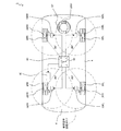
まず図1は、第1実施形態の監視システム1全体の構成を表す説明図である。
図1に示すように、本第1実施形態の監視システム1は、車両4の車体6側にて前後左右の各車輪8FL,8FR,8RL,8RRの近くに設けられて要求信号を無線にて送信する送信機10FL,10FR,10RL,10RRと、各車輪8FL〜8RRに設けられ、要求信号を受信するとその車輪8FL〜8RRのタイヤ状態を検出し、その検出結果を含んだ応答信号を無線にて送信する検出装置20FL,20FR,20RL,20RRと、車体6側に設けられ、応答信号を受信する受信機50と、車体6側に設けられ、受信機50が受信した応答信号に基づいて車輪8FL〜8RRのタイヤ状態を監視する監視装置60と、車両4の運転席近傍に設けられ、監視装置60による監視結果を乗員に報知するための表示装置80と、を備えている。
First, FIG. 1 is an explanatory diagram showing the overall configuration of the monitoring system 1 of the first embodiment.
As shown in FIG. 1, the monitoring system 1 of the first embodiment is provided near the front, rear, left, and right wheels 8FL, 8FR, 8RL, 8RR on the
また、車両4のトランク内の応急用タイヤ収納部に収納された応急用タイヤSTには、検出装置20FL〜20RRと同じ機能を有した検出装置20STが設けられている。
尚、車輪8FL〜8RR、送信機10FL〜10RR及び検出装置20FL〜20RR,20STの符号に付してあるアルファベットの添え字FL,FR,RL,RR,STは、「FL」が左前輪に対応するものであることを示し、「FR」が右前輪に対応するものであることを示し、「RL」が左後輪に対応するものであることを示し、「RR」が右後輪に対応するものであることを示し、「ST」が応急用タイヤSTに対応するものであることを示す。そして、以下の説明において、各車輪8FL〜8RR、各送信機10FL〜10RR及び各検出装置20FL〜20RR,20STの位置関係を特に区別しない場合には、符号として、そのアルファベットの添え字FL,FR,RL,RR,STを削除したものを用いる。つまり、車輪8FL〜8RRならば車輪8であり、送信機10FL〜10RRならば送信機10であり、検出装置20FL〜20RR,20STならば検出装置20である。
The emergency tire ST stored in the emergency tire storage section in the trunk of the
In addition, the alphabetical suffixes FL, FR, RL, RR, and ST attached to the symbols of the wheels 8FL to 8RR, the transmitters 10FL to 10RR, and the detectors 20FL to 20RR and 20ST are “FL” corresponding to the left front wheel. "FR" corresponds to the right front wheel, "RL" indicates that it corresponds to the left rear wheel, and "RR" corresponds to the right rear wheel "ST" indicates that it corresponds to the emergency tire ST. In the following description, when the positional relationship among the wheels 8FL to 8RR, the transmitters 10FL to 10RR, and the detection devices 20FL to 20RR and 20ST is not particularly distinguished, the alphabetic suffixes FL and FR are used as symbols. , RL, RR, ST are deleted. That is, the wheels 8FL to 8RR are wheels 8, the transmitters 10FL to 10RR are transmitters 10, and the detection devices 20FL to 20RR and 20ST are detection devices 20.
各検出装置20は、各送信機10から受信した要求信号(電波)を動作電力にして動作するように構成されている。また、本第1実施形態において、各検出装置20から送信される応答信号は極超短波帯の信号(例えば、315MHzの信号であり、以下、RF信号という)である。尚、検出装置20は、例えば、車輪8のバルブに取り付けられている。 Each detection device 20 is configured to operate using the request signal (radio wave) received from each transmitter 10 as the operating power. In the first embodiment, the response signal transmitted from each detection device 20 is a signal in the very high frequency band (for example, a 315 MHz signal, hereinafter referred to as an RF signal). In addition, the detection apparatus 20 is attached to the valve | bulb of the wheel 8, for example.
一方、各送信機10は、要求信号として、長波帯の信号(例えば、周波数120kHz〜135kHz程度の信号であり、以下、LF信号という)を送信するように構成されている。そして、各送信機10から送信される要求信号の送信電力は、当該送信機10からの要求信号を受信した検出装置20のうち、その送信機10に対応する車輪8側の検出装置20が、当該送信機10から受信した要求信号によって動作を開始してから応答信号を送信するまでに充分な動作電力を生成する程度に設定されている(図1に一点鎖線で示す要求信号送信エリア参照)。また、要求信号は無変調のLF信号である。 On the other hand, each transmitter 10 is configured to transmit a long-wave band signal (for example, a signal having a frequency of about 120 kHz to 135 kHz, hereinafter referred to as an LF signal) as a request signal. And the transmission power of the request signal transmitted from each transmitter 10 is the detection device 20 on the wheel 8 side corresponding to the transmitter 10 among the detection devices 20 that have received the request signal from the transmitter 10. It is set to a level that generates sufficient operating power from the start of operation according to the request signal received from the transmitter 10 until the response signal is transmitted (refer to the request signal transmission area indicated by the one-dot chain line in FIG. 1). . The request signal is an unmodulated LF signal.
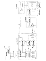
次に、検出装置20、受信機50、送信機10、監視装置60、及び、表示装置80の構成について図2を用い説明する。尚、検出装置20及び送信機10は、それぞれ、同一構成であることから、図2には、各車輪8毎に対応する、一つの検出装置20と一つの送信機10とを記載している。
Next, configurations of the detection device 20, the
まず、検出装置20は、図2に示すように、送信機10から送信された要求信号(LF信号)を受信する受信アンテナ22と、受信アンテナ22により受信された要求信号を整流して図示しない蓄電用のコンデンサを充電し、そのコンデンサに充電された電力により直流定電圧を生成して検出装置20の内部回路に供給する電源回路24と、受信アンテナ22により受信された要求信号の電界強度を検出して該電界強度をA/D変換し、そのAD変換値を表すRSSI値Nrを出力するRSSI検出回路26と、車輪8のタイヤ内の空気圧を検出する圧力センサ28と、車輪8のタイヤ内の温度を検出する温度センサ30と、RSSI検出回路26から出力されたRSSI値Nrが閾値Nよりも大きいか否かを判定し、RSSI値Nrが閾値Nよりも大きいと判定した場合に、圧力センサ28及び温度センサ30を介してタイヤ状態(空気圧及び温度)を検出すると共にその検出結果(検出データ)及び当該検出装置20が設けられた車輪8固有の識別情報(以下、センサIDという)を出力する制御回路32と、極超短波帯の正弦波を発生すると共に該正弦波を制御回路32から出力される検出データ及びセンサID等の出力データで変調することにより該出力データを含む応答信号を生成する送信回路34と、送信回路34にて生成される応答信号を送信する送信アンテナ36と、を備えている。
First, as illustrated in FIG. 2, the detection device 20 rectifies the request signal received by the
尚、RSSI検出回路26、制御回路32、送信回路34等、検出装置20の内部回路は、全て、電源回路24にて生成された直流定電圧を受けて動作するようにされている。これに対し、送信機10、受信機50及び監視装置60は、所謂車載機器であることから、車両4に搭載された車載バッテリから電源供給を受けて動作するようになっている。
The internal circuits of the detection device 20 such as the
更に、検出装置20は、外部機器である設定装置100のコネクタ100aと接続するためのコネクタ38と、制御回路32を設定装置100と通信させる通信回路40と、も備えている。そして、検出装置20のコネクタ38と設定装置100のコネクタ100aとを接続すると、検出装置20と設定装置100とが通信回路40を介して通信可能となり、しかも、設定装置100から制御回路32及び通信回路40に電力が供給されるようになっている。また、コネクタ38,100a同士を接続した際には、設定装置100の操作部100bにより入力されたデータが制御回路32に送信されるようになっている。
Furthermore, the detection device 20 includes a
また、制御回路32は、CPU、ROM、RAM等を中心とするマイクロコンピュータにて構成されており、RSSI値Nrと比較するための閾値NやセンサIDが予め記憶された不揮発性のメモリであるEEPROM32aを備えている。そして、制御回路32は、このEEPROM20aに登録された閾値NとRSSI値Nrとを大小比較する。
The
ここで、本実施形態において、各検出装置20の閾値Nは、以下の(1−1)〜(1−3)の条件を満たすように予め設定されている。尚、各検出装置20の閾値Nは、検出装置20STの閾値Nも含めて互いに同じ値に設定されている。 Here, in the present embodiment, the threshold value N of each detection device 20 is set in advance so as to satisfy the following conditions (1-1) to (1-3). The threshold value N of each detection device 20 is set to the same value including the threshold value N of the detection device 20ST.
(1−1)閾値Nは、車輪8側の各検出装置20FL〜20RRが、それに対応する各送信機10FL〜10RRからの要求信号を受信した際にRSSI検出回路26から出力されるRSSI値Nrよりも小さい値である。
(1-1) The threshold value N is an RSSI value Nr output from the
(1−2)閾値Nは、車輪8側の検出装置20FL〜20RRが本監視システム1と同じ監視システムを搭載した他の車両からの要求信号を受信した際にRSSI検出回路26から出力されるRSSI値Nrの最大値よりも大きい値である。
(1-2) The threshold value N is output from the
(1−3)閾値Nは、応急用タイヤST側の検出装置20STが送信機10からの要求信号を受信した際にRSSI検出回路26から出力されるRSSI値Nrの最大値よりも大きい値である。
(1-3) The threshold value N is a value larger than the maximum value of the RSSI value Nr output from the
このため、例えば、検出装置20RLでは、図3(a)に示すように、送信機10RLからの要求信号を受信したときにだけ、RSSI値Nrが閾値Nよりも大きくなることとなる。尚、検出装置20RLだけでなく、残りの車輪8FL,8FR,8RR側の検出装置20FL,20FR,20RRについても同様に、それら各検出装置20FL,20FR,20RRが自己に対応する送信機10FL,10FR,10RRからの要求信号を受信したときにだけ、RSSI値Nrが閾値Nよりも大きくなる。一方、検出装置20STについては、図3(b)に示すように、どの送信機10からの要求信号を受信したとしても、RSSI値Nrが閾値Nよりも大きくなることはない。 Therefore, for example, in the detection device 20RL, the RSSI value Nr becomes larger than the threshold value N only when a request signal is received from the transmitter 10RL as shown in FIG. Note that not only the detection device 20RL but also the detection devices 20FL, 20FR, and 20RR on the remaining wheels 8FL, 8FR, and 8RR side, similarly, each of the detection devices 20FL, 20FR, and 20RR corresponds to the transmitter 10FL, 10FR corresponding to itself. The RSSI value Nr becomes larger than the threshold value N only when a request signal from 10RR is received. On the other hand, as shown in FIG. 3B, the RSSI value Nr does not become larger than the threshold value N for the detection device 20ST, regardless of which transmitter 10 receives the request signal.
即ち、各検出装置20における閾値Nは、車輪8側の各検出装置20FR〜20RRがそれに対応する各送信機10FR〜10RRから要求信号を受信した場合にだけ、該受信したRSSI値Nrよりも小さくなるように予め設定されている。 That is, the threshold value N in each detection device 20 is smaller than the received RSSI value Nr only when each detection device 20FR to 20RR on the wheel 8 side receives a request signal from the corresponding transmitter 10FR to 10RR. It is preset so that
尚、図3は、検出装置20における閾値Nと該検出装置20が各送信機10からの要求信号を受信したときのRSSI値Nrとの関係を説明する説明図であり、図3(a)は、検出装置20RLについて閾値NとRSSI値Nrとの関係を説明する説明図であり、図3(b)は、検出装置20STについて閾値NとRSSI値Nrとの関係を説明する説明図である。 FIG. 3 is an explanatory diagram for explaining the relationship between the threshold value N in the detection device 20 and the RSSI value Nr when the detection device 20 receives a request signal from each transmitter 10. FIG. These are explanatory drawings explaining the relationship between the threshold value N and the RSSI value Nr for the detection device 20RL, and FIG. 3B is an explanatory diagram explaining the relationship between the threshold value N and the RSSI value Nr for the detection device 20ST. .
また、送信アンテナ36は、応答信号(RF信号)を送信可能なアンテナにて構成されており、受信アンテナ22は、送信機10から送信された要求信号(LF信号)を受信するために、コンデンサとコイルとの共振を利用して要求信号を受信する共振アンテナにて構成されている。
The
次に、受信機50は、検出装置20の送信アンテナ36から送信されてくる応答信号を受信可能な受信アンテナ52と、検出装置20からの応答信号を受信アンテナ52を介して受信し、該受信した応答信号を復調する受信回路54とから構成されている。
Next, the
次に、送信機10は、検出装置20の受信アンテナ22と同じ共振アンテナからなる送信アンテナ12と、監視装置60から出力された送信指令に従い要求信号を生成して該要求信号で送信アンテナ12を駆動する(換言すれば共振させる)ことでその送信アンテナ12から要求信号を送信させる駆動回路14とから構成されている。
Next, the transmitter 10 generates a request signal in accordance with the transmission command output from the
次に、監視装置60は、各送信機10(詳しくは10FL〜10RR)に対して、それぞれ、送信指令を出力するための複数(本実施形態では前後左右の車輪8用の4個)のインターフェイス回路(以下、I/F回路という)62と、これら各I/F回路62を介して、各送信機10に順次送信指令を出力することで、各送信機10から対応する検出装置20に要求信号を送信させる制御回路64と、を備えている。
Next, the
ここで、制御回路64は、検出装置20の制御回路32と同様、CPU、ROM、RAM等を中心とするマイクロコンピュータにて構成されている。
一方、表示装置80は、各車輪8毎のタイヤ状態の検出結果をそれぞれ表示するための4つの表示部(本実施形態では前後左右の車輪8用の4箇所)を備えている。
Here, like the
On the other hand, the
そして、制御回路64は、要求信号の送信後、検出装置20からの応答信号が受信アンテナ52で受信されて該応答信号が受信回路54にて復調されると、その復調された応答信号に含まれる検出データ及びセンサIDを取り込み、該センサIDから、今回取り込んだ検出データが何れの車輪8のものであるかを特定すると共に、その取り込んだ検出データに基づいて上記特定した車輪8のタイヤ状態(空気圧の低下、温度上昇)の異常の有無を判断する異常有無判定を行う。
Then, after the transmission of the request signal, the
そして更に、制御装置64は、上記取り込んだ検出データの値(即ち、空気圧の値と温度の値)を、表示装置80の4つの表示部のうち、上記特定した車輪8に対応する表示部に表示させるが、もし、その特定した車輪8に関して上記異常有無判定によりタイヤ状態に異常があると判断した場合には、該表示部に表示させる数値の色を、正常を示す表示色(本実施形態では青)から、異常を示す表示色(本実施形態では赤)に変えるようになっている。
Further, the
尚、上記異常有無判定では、空気圧と温度との各々について異常の有無を判断するようになっており、空気圧と温度との何れか一方だけが異常と判断する場合があり得るが、そのような場合でも、空気圧と温度との両方の値を赤色で表示するようにしても良いし、また、空気圧と温度とのうち、異常と判断した方の値だけを赤色で表示するようにしても良い。 In the above-described abnormality determination, whether there is an abnormality for each of the air pressure and the temperature is determined, and only one of the air pressure and the temperature may be determined to be abnormal. Even in this case, both the air pressure and temperature values may be displayed in red, or only the value determined to be abnormal among the air pressure and temperature may be displayed in red. .
次に、上述の如く構成された監視装置60内の制御回路64が車両4の各車輪8のタイヤ状態を監視するために実行するタイヤ状態監視処理、及び、この処理に連動して検出装置20内の制御回路32にて実行される応答処理を、図4に示すフローチャートに沿って詳しく説明する。
Next, a tire condition monitoring process executed by the
尚、図4(A)に示すタイヤ状態監視処理は、イグニッションスイッチがオンされエンジンが起動された後に、所定の監視時間間隔Tintで周期的に実行される処理であり、図4(B)に示す応答処理は、そのタイヤ状態監視処理の実行により要求信号を受けた検出装置20にて実行される処理である。また、本実施形態のタイヤ状態監視処理は、各車輪8を、例えば8FL→8FR→8RL→8RRの順番に監視対象として実行されるようになっている。 The tire condition monitoring process shown in FIG. 4 (A) is a process that is periodically executed at a predetermined monitoring time interval Tint after the ignition switch is turned on and the engine is started, as shown in FIG. 4 (B). The response process shown is a process executed by the detection device 20 that has received the request signal by executing the tire condition monitoring process. Further, the tire condition monitoring process of the present embodiment is executed with each wheel 8 as a monitoring target in the order of 8FL → 8FR → 8RL → 8RR, for example.
図4に示す如く、監視装置60がタイヤ状態監視処理を開始すると、まずステップ110(以下、ステップをSと記載する)にて、4つの送信機10のうち、現在監視対象となっている車輪8の近くに配置された送信機(以下、監視対象送信機という)10から、検出装置20側で電源回路24が電源電圧を生成して内部回路を動作させるのに必要な時間、要求信号を連続的に送信させる。
As shown in FIG. 4, when the
すると、監視対象送信機10の近くに位置する車輪8側の検出装置(以下、監視対象検出装置という)20では、電源回路24が、監視対象送信機10からの要求信号によって電源電圧を生成し当該検出装置20の内部回路に動作電源を供給し始めると、検出装置20側の制御回路32が、応答処理を開始する。
Then, in the detection device 20 on the wheel 8 side (hereinafter referred to as the monitoring target detection device) 20 located near the monitoring target transmitter 10, the
そして、この応答処理では、まずS210にて、RSSI検出回路26から出力されたRSSI値Nr(即ち、受信アンテナ22により受信された要求信号の電界強度の値)を読み取って、そのRSSI値Nrが、EEPROM32a内に記憶されている閾値Nよりも大きいか否かを判定し、RSSI値Nrが閾値Nよりも小さいと判定すると、そのまま応答処理を終了し、RSSI値Nrが閾値Nよりも大きいと判定すると、S220に進む。
In this response process, first, in S210, the RSSI value Nr output from the RSSI detection circuit 26 (that is, the value of the electric field strength of the request signal received by the receiving antenna 22) is read, and the RSSI value Nr is calculated. If it is determined whether or not the threshold value Nr stored in the
続いて、S220では、圧力センサ28及び温度センサ30を用いてタイヤ内の空気圧及び温度を検出し、続くS230にて、その検出データと当該監視対象検出装置20のセンサIDとを送信回路34に出力することで、送信回路34から応答信号を送信させた後、当該応答処理を終了する。
Subsequently, in S220, the air pressure and temperature in the tire are detected using the
このため、監視装置60側では、S110にて要求信号を送信した後は、S120に移行して、所定時間の間、受信機50にて監視対象検出装置20からの応答信号が受信されたか否かを判断することにより、監視対象検出装置20から応答信号が送信されてくるのを待つ。尚、監視装置60側の制御回路64は、応答信号を受信した受信回路54により復調された検出データ及びセンサID等の受信データが入力されたときに、受信機50にて監視対象検出装置20からの応答信号が受信されたと判断する。
Therefore, on the
そして、受信機50にて応答信号が受信されたと判断すると、続くS130に移行して、その応答信号に含まれていた検出データとセンサIDを受信回路54から取り込んで、その取り込んだセンサIDから、今回受信した応答信号の送信元である車輪8(詳しくは、応答信号の送信元である検出装置20が設けられている車輪8)を特定すると共に、同じく取り込んだ検出データから、その特定した車輪8のタイヤ状態の異常の有無を判断する。
If it is determined that the response signal is received by the
続いて、S140では、表示装置80の4つの表示部のうち、S130にて特定した車輪8に対応する表示部に、上記S130で受信回路54から取り込んだ検出データの値を、上記S130での異常有無判断結果に応じた表示色で表示させる。つまり、前述したように、正常なら青色で、異常なら赤色で表示させる。そして、こうした表示色の切り換えにより、監視装置60による監視結果が乗員に報知される。
Subsequently, in S140, the value of the detection data captured from the receiving
このS140の処理が終わると、当該タイヤ状態監視処理を一旦終了する。そして、その後、前述した監視時間間隔Tintが経過すると、次の車輪8を監視対象として当該タイヤ状態監視処理が再び実行される。 When the process of S140 is completed, the tire condition monitoring process is temporarily ended. Thereafter, when the above-described monitoring time interval Tint elapses, the tire state monitoring process is executed again with the next wheel 8 as a monitoring target.
一方、S120にて応答信号を受信できないと判断した場合は、何らかの通信異常が生じているものと判断して、当該タイヤ状態監視処理を一旦終了し、その後、監視時間間隔Tintが経過すると、次の車輪8を監視対象として当該タイヤ状態監視処理が再び実行される。 On the other hand, if it is determined in S120 that the response signal cannot be received, it is determined that some kind of communication abnormality has occurred, the tire condition monitoring process is once terminated, and then, after the monitoring time interval Tint has passed, The tire state monitoring process is executed again with the wheel 8 as a monitoring target.
以上のように、本第1実施形態の監視システム1においては、各車輪8の検出装置20に対応して、送信機10が設けられており、監視装置60は、その送信機10のうち、選択した送信機10から、要求信号を送信させることにより、そのとき監視対象となっている自車両の車輪8の検出装置20を起動させる。
As described above, in the monitoring system 1 of the first embodiment, the transmitter 10 is provided corresponding to the detection device 20 of each wheel 8, and the
また、要求信号を受信することにより起動した検出装置20は、RSSI検出回路26からのRSSI値Nrが閾値Nより大きいと判定した場合に、検出データ及びセンサIDを含んだ応答信号を送信する。
In addition, when the detection device 20 activated by receiving the request signal determines that the RSSI value Nr from the
従って、本第1実施形態の監視システム1によれば、監視装置60側から送信した要求信号にて起動し、RSSI値Nrが閾値Nよりも大きいと判定した検出装置20だけが、監視装置60に対して応答信号を送信することとなるため、各検出装置20は、当該検出装置20に対応しない自車両4の送信機10から送信された要求信号や他の車両側から送信された要求信号によって応答信号を送信することはない。更に、当該車両4の送信機10からの要求信号によって、検出装置20STや他の車両側から応答信号が送信されてくることもない。
Therefore, according to the monitoring system 1 of the first embodiment, only the detection device 20 activated by the request signal transmitted from the
つまり、本実施形態の監視システム1では、監視対象送信機10からの要求信号に対して、監視対象検出装置(即ち、監視対象送信機10の近くに位置する自車両4の車輪8側の検出装置)20だけが、応答信号を送信することとなる。
That is, in the monitoring system 1 of the present embodiment, in response to a request signal from the monitoring target transmitter 10, a monitoring target detection device (that is, detection on the wheel 8 side of the
よって、上述した(A)及び(B)の問題を解決することができる。
また、検出装置20は、送信機10からの要求信号を用いて電源電圧を生成するように構成されているため、給電用の電池を車輪8側に設けなくても良く、車輪8側の重量を小さくすることができる。
Therefore, the above problems (A) and (B) can be solved.
Further, since the detection device 20 is configured to generate a power supply voltage using a request signal from the transmitter 10, it is not necessary to provide a battery for power supply on the wheel 8 side, and the weight on the wheel 8 side. Can be reduced.
また、本監視システム1では、設定装置100を用いることで、閾値Nを変更することができるようになっている。
即ち、閾値Nを変更する際には、まず、検出装置20のコネクタ38と設定装置100のコネクタ100aとを接続し、続いて設定装置100の操作部100bにて新規の閾値Nを入力すると、その新規の閾値Nを表す新規閾値データが設定装置100から通信回路40を介して制御回路32へ送信され、検出装置20側の制御回路32が、それまでの閾値Nに代えて、設定装置100から取得した上記新規の閾値NをEEPROM32aに記憶することとなる。
Further, in the monitoring system 1, the threshold value N can be changed by using the
That is, when changing the threshold value N, first, the
例えば、表示装置80の4つの表示部の各々に表示されている各車輪8毎のタイヤ状態の検出値のうち、何れかの値が変化しなくなった場合、その値が表示されている表示部に対応する送信機(以下、特定送信機という)10の送信能力が経時変化で変わる等して、特定送信機10からの要求信号に対する検出装置20の反応性が悪化した(即ち、検出装置20が特定送信機10からの要求信号を受信しても応答信号を送信しなくなった)ことが考えられる。この場合、反応性が悪化した検出装置20における閾値Nを、それまでの閾値Nよりも小さい値に変更することでその問題を解消することができる。
For example, when one of the detected values of the tire state for each wheel 8 displayed on each of the four display units of the
また、例えば、検出装置20STにおける閾値Nを、受信アンテナ22により受信した要求信号のRSSI値Nrの最大値よりも充分に大きい値に変更しても良い。
従って、本監視システム1によれば、閾値Nを最適な値に調整することが可能となる。
Further, for example, the threshold value N in the detection device 20ST may be changed to a value sufficiently larger than the maximum value of the RSSI value Nr of the request signal received by the
Therefore, according to the monitoring system 1, the threshold value N can be adjusted to an optimum value.
尚、本第1実施形態では、受信機50が受信手段に相当し、送信機10が送信手段に相当し、S210の処理が判定手段に相当している。また、受信アンテナ22及び電源回路が受信兼電力生成手段に相当し、受信アンテナ22により受信した要求信号の電界強度が受信信号強度に相当している。
In the first embodiment, the
次に、第2実施形態の監視システムについて、図5及び図6を用い説明する。尚、図5は、第2実施形態の監視システム2全体の構成を表す説明図であり、図6は、同監視システム2の構成を表すブロック図である。また、図5及び図6において、第1実施形態の監視システム1と同様の構成要素については、同じ符号を付しているため、詳細な説明は省略する。 Next, a monitoring system according to the second embodiment will be described with reference to FIGS. FIG. 5 is an explanatory diagram illustrating the overall configuration of the monitoring system 2 according to the second embodiment, and FIG. 6 is a block diagram illustrating the configuration of the monitoring system 2. 5 and 6, the same components as those in the monitoring system 1 of the first embodiment are denoted by the same reference numerals, and detailed description thereof is omitted.
第2実施形態の監視システム2は、第1実施形態の監視システム1と比較すると、応答信号がRF信号でなくLF信号である点が異なっている。つまり、本監視システム2では、応答信号が要求信号と同じ長波帯の信号である。 The monitoring system 2 of the second embodiment is different from the monitoring system 1 of the first embodiment in that the response signal is not an RF signal but an LF signal. That is, in this monitoring system 2, the response signal is a signal in the same long wave band as the request signal.
このため、検出装置20では、送信回路34及び送信アンテナ36が設けられておらず、その代わりに、受信アンテナ22が要求信号を受信するだけでなく応答信号を送信するための送受信アンテナとしても用いられている。このため、以下第2実施形態の説明では、受信アンテナ22を改めて送受信アンテナ22という。
For this reason, in the detection apparatus 20, the
そして更に、検出装置20は、送受信アンテナ22から応答信号を送信させる駆動回路42を備えている。そして、駆動回路42は、長波帯の正弦波を発生すると共に該正弦波を制御回路32から出力される出力データ(検出データ及びセンサID)で変調することにより出力データを含む応答信号(LF信号)を生成して、その応答信号を送受信アンテナ22から送信させるようになっている。
Furthermore, the detection apparatus 20 includes a
一方、車体6側では、要求信号の送信と共に応答信号の受信をすることができるように、送信機10に代えて、送受信機11が各車輪8の近くにそれぞれ設けられている。このため、車体6側には、受信機50が設けられていない。
On the other hand, on the
そして、送受信機11は、要求信号の送信及び応答信号の受信をする送受信アンテナ12と、駆動回路14と、送受信アンテナ12により受信された応答信号を増幅する増幅回路16と、増幅回路16からの受信信号(増幅された応答信号)を復調し、復調された信号に含まれる検出データ及びセンサIDを制御回路64に出力する受信回路18と、を備えている。尚、送受信アンテナ12は、第1実施形態の送信アンテナ12と同じ構成の共振アンテナであるため、同じ符号を付している。
The transceiver 11 includes a transmission / reception antenna 12 that transmits a request signal and receives a response signal, a
つまり、本第2実施形態の監視システム2では、検出装置20の送受信アンテナ22が、要求信号の受信及び応答信号の送信をするようになっていると共に、送受信機11の送受信アンテナ12が、要求信号の送信及び応答信号の受信をするようになっている。
That is, in the monitoring system 2 of the second embodiment, the transmission /
このため、図4のタイヤ状態監視処理のS110にて、監視装置60が、現在監視対象となっている車輪8の近くに配置された送受信機(以下、監視対象送受信機という)11から要求信号を送信させた場合、該要求信号を受けた監視対象検出装置20は応答信号を送受信アンテナ22から送信することとなり、監視対象送受信機11は、送受信アンテナ12にて応答信号を受信することとなる。
Therefore, in S110 of the tire condition monitoring process of FIG. 4, the
以上のような第2実施形態の監視システム2によっても、監視対象送受信機11からの要求信号に対して、監視対象検出装置20だけが応答信号を送信することに変わりはないため、第1実施形態の監視システム1と同様に(A)及び(B)の問題を解決することができる。 Even in the monitoring system 2 of the second embodiment as described above, only the monitoring target detection device 20 transmits a response signal to the request signal from the monitoring target transceiver 11, so that the first embodiment The problems (A) and (B) can be solved as in the monitoring system 1 of the embodiment.
ところで、本第2実施形態の監視システム2では、応答信号を受信するための送受信アンテナ12を監視対象となる車輪8の数だけ備えている。このため、監視装置60が各検出装置20から検出データを取得する(応答信号を受信する)際には、各送受信機11から要求信号を同時に送信させるようにしても良い。
By the way, in the monitoring system 2 of this 2nd Embodiment, the transmission / reception antenna 12 for receiving a response signal is provided with the number of the wheels 8 used as monitoring object. For this reason, when the
尚、本第2実施形態では、送受信機11が送信手段及び受信手段に相当している。
次に、第3実施形態の監視システムについて、図7及び図8を用い説明する。尚、図7は、第3実施形態の監視システム3の構成を表すブロック図であり、図8は、同実施形態の検出装置20にて実行される応答処理を表すフローチャートである。また、第1実施形態と同様の構成要素及び処理については、同じ符号を付しているため、詳細な説明は省略する。
In the second embodiment, the transceiver 11 corresponds to a transmission unit and a reception unit.
Next, a monitoring system according to a third embodiment will be described with reference to FIGS. FIG. 7 is a block diagram showing the configuration of the monitoring system 3 of the third embodiment, and FIG. 8 is a flowchart showing response processing executed by the detection device 20 of the embodiment. Moreover, since the same code | symbol is attached | subjected about the component and process similar to 1st Embodiment, detailed description is abbreviate | omitted.
第3実施形態の監視システム3は、第1実施形態の監視システム1と比較すると、閾値Nの変更を車体6側から行うことができる点が異なっている。
このため、車体6側では、監視装置60が設定装置100と接続可能になっていると共に、新規の閾値Nを含んだLF信号が送信機10から送信されるようになっており、検出装置20では、図4の応答処理に代えて、後述する図8の応答処理が実行されるようになっていると共にコネクタ38及び通信回路40が設けられていない。尚、以下の説明では、新規の閾値Nを含んだLF信号を閾値変更信号という。
The monitoring system 3 according to the third embodiment is different from the monitoring system 1 according to the first embodiment in that the threshold value N can be changed from the
Therefore, on the
具体的に説明すると、本監視システム3は、第1実施形態の監視システム1と比較すると、下記の(3−1)〜(3−6)の点が異なっている。
(3−1)監視装置60は、設定装置100のコネクタ100aと接続するためのコネクタ66と、制御回路64を設定装置100と通信させる通信回路68と、を備えている。
More specifically, the monitoring system 3 differs from the monitoring system 1 of the first embodiment in the following points (3-1) to (3-6).
(3-1) The
(3−2)また、設定装置100では、操作部100bにて新規の閾値Nの入力だけでなく、4つの車輪8の何れかを選択することができるようになっている。このため、設定装置100を監視装置60に接続して、操作部100bにて車輪8の選択及び新規の閾値Nの入力をした際には、どの車輪8が選択されたかを示す車輪選択データ及び新規閾値データが監視装置60側の制御回路64に入力されることとなる。
(3-2) Moreover, in the
(3−3)監視装置60側の制御回路64は、車輪選択データ及び新規閾値データが入力されると、車輪選択データにより選択された車輪8に対応する送信機10を判断し、その送信機10に新規閾値データを送信指令と共にI/F回路62を介して出力するようになっている。
(3-3) When the wheel selection data and the new threshold data are input, the
(3−4)送信機10は、駆動回路14に代えて、駆動回路19を備えている。そして、駆動回路19は、新規閾値データ及び送信指令が入力されると、長波帯の正弦波を発生すると共に該正弦波を新規閾値データで変調することにより閾値変更信号を生成して、その閾値変更信号を送信アンテナ12から送信させるようになっている。また、駆動回路19は、送信指令だけが入力された場合、要求信号を生成して送信アンテナ12から送信させるようになっている。つまり、駆動回路19に送信指令だけが入力された場合、当該駆動回路19は、長波帯の正弦波を変調しないでそのまま送信アンテナ12から送信させる。
(3-4) The transmitter 10 includes a
そして、検出装置20では、閾値変更信号を受信した場合も、電源回路24がその閾値変更信号によって電源電圧を生成して当該検出装置20の内部回路に供給するようになっている。
In the detection device 20, even when the threshold change signal is received, the
(3−5)検出装置20は、受信回路44を備えている。そして、受信回路44は、受信アンテナ22を介して受信した閾値変更信号を復調し、復調された閾値変更信号に含まれる新規閾値データを制御回路32に出力するようになっている。
(3-5) The detection device 20 includes a
(3−6)検出装置20では、電源回路24が要求信号又は閾値変更信号によって電源電圧を生成し動作電源を供給し始めると、制御回路32が図8の応答処理を開始する。
そして、この応答処理では、まず、S200にて、受信した信号に新規閾値データが含まれていたか否かを判定する。尚、S200では、受信回路44から新規閾値データが入力された場合に閾値変更信号を受信したと判断し(S200:YES)、当該応答処理を開始して所定時間経過しても新規閾値データが入力されなかった場合に要求信号を受信したと判断する(S200:NO)。
(3-6) In the detection device 20, when the
In this response process, first, in S200, it is determined whether or not new threshold data is included in the received signal. In S200, it is determined that a threshold value change signal has been received when new threshold value data is input from the receiving circuit 44 (S200: YES), and the new threshold value data remains after a predetermined time has elapsed since the start of the response process. If it is not input, it is determined that a request signal has been received (S200: NO).
そして、S200にて、要求信号を受信したと判断した場合(S200:NO)には、上述したS210に移行して、以降は図4の応答処理と同じ処理を実行する。一方、S200にて、閾値変更信号を受信したと判断した場合(S200:YES)は、S205に移行し、それまでの閾値Nに代えて新規の閾値NをEEPROM32aに記憶して、当該応答処理を終了する。
If it is determined in S200 that the request signal has been received (S200: NO), the process proceeds to S210 described above, and thereafter, the same process as the response process in FIG. 4 is executed. On the other hand, if it is determined in S200 that the threshold value change signal has been received (S200: YES), the process proceeds to S205, where the new threshold value N is stored in the
以上のような構成の監視システム3では、車両4駐車中に監視装置のコネクタ66に設定装置100のコネクタ100aを接続してから、設定装置100の操作部100bにて例えば車輪8RLを選択すると共に新規の閾値Nを入力すると、送信機10RLが閾値変更信号を送信することとなり、該閾値変更信号を受信した検出装置20RLでは、閾値Nが、それまでの値から新規の閾値Nに変更されることとなる。
In the monitoring system 3 configured as described above, the
以上のような第3実施形態の監視システム3によれば、車体6側から閾値Nを変更することができる。
ところで、本監視システム3では、検出装置20が閾値変更信号を受信した場合、その検出装置20は応答信号を送信しない(即ち、S210〜S230の処理を行わない)ように構成されていたが、検出装置20が閾値変更信号を受信した場合も、応答信号を送信するように構成しても良い。
According to the monitoring system 3 of the third embodiment as described above, the threshold value N can be changed from the
By the way, in this monitoring system 3, when the detection device 20 receives the threshold value change signal, the detection device 20 is configured not to transmit a response signal (that is, not perform the processing of S210 to S230). Even when the detection device 20 receives the threshold value change signal, the response signal may be transmitted.
この場合、検出装置20側の制御回路32は、図8の処理を開始してS200にて閾値変更信号を受信したと判断してからS205の処理を行った後に、S210に進むようにすれば良い。尚、この変形例において、閾値変更信号は要求信号に相当する。
In this case, the
また、本監視システム3では、閾値Nを変更する場合、閾値Nを変更したい車輪8を選択すると共に新規の閾値Nを入力したときにその選択された車輪8に対応する送信機10から閾値変更信号が送信されるようになっていたが、車輪8の選択及び新規の閾値Nの入力をしたときに閾値信変更信号を送信せずに、図4のタイヤ状態監視処理のS110で送信される要求信号に新規の閾値Nを含ませて、その信号を送信するように構成しても良い。 In the monitoring system 3, when the threshold value N is changed, the wheel 8 for which the threshold value N is desired to be changed is selected, and when a new threshold value N is input, the threshold value is changed from the transmitter 10 corresponding to the selected wheel 8. The signal is transmitted, but when the wheel 8 is selected and a new threshold value N is input, the threshold signal change signal is not transmitted, but is transmitted in S110 of the tire condition monitoring process of FIG. A new threshold value N may be included in the request signal, and the signal may be transmitted.
この場合、監視装置60側の制御回路64は、入力された車輪選択データ及び新規閾値データを当該制御回路64内の不揮発性メモリ(例えば、EEPROMやフラッシュROM)に記憶すると共に、S110の処理のときにその記憶されている車輪選択データを読み取って、該車輪選択データが現在監視対象となっている車輪8を表すデータであるか否かを判定し、肯定判定した場合に監視対象送信機10から閾値変更信号を送信させるように構成されていれば良い。一方、検出装置20側では、S205の処理を実行したらS210に移行するようにすれば良い。そして、この変形例において、閾値変更信号と要求信号との両方が要求信号に相当することとなる。
In this case, the
以上、本発明の一実施形態について説明したが、本発明は、種々の形態を採り得ることは言うまでもない。
検出装置20は、電池によって動作するように構成されていても良い。この場合、検出装置20には電源回路24が設けられていなくても良い。
As mentioned above, although one Embodiment of this invention was described, it cannot be overemphasized that this invention can take a various form.
The detection device 20 may be configured to operate with a battery. In this case, the
また、本実施形態では、S210にて、RSSI値Nrが閾値Nよりも小さいと判定(否定判定)した場合、そのまま応答処理を終了していたが、これに限らず、S210にて否定判定した場合、所定時間Tが経過してから応答信号を送信するようにしても良い。この場合、上記所定時間Tを、上記監視時間間隔Tintよりも短い範囲で、各検出装置20毎異なるように設定すれば、(A)及び(B)の問題を解決することができる。 In this embodiment, when it is determined in S210 that the RSSI value Nr is smaller than the threshold value N (determination determination), the response process is terminated as it is, but not limited thereto, a negative determination is made in S210. In this case, the response signal may be transmitted after the predetermined time T has elapsed. In this case, if the predetermined time T is set to be different for each detection device 20 within a range shorter than the monitoring time interval Tint, the problems (A) and (B) can be solved.
また、要求信号の送信電力が変更可能となるように構成されていれば、上述の如く表示装置80の4つの表示部の各々に表示されている各車輪8毎のタイヤ状態の検出値のうち、何れかの値が変化しなくなった場合、閾値Nを変更する代わりに、要求信号の送信電力を変更することで、閾値Nが最適な値となるようにしても良い。
Further, if the transmission power of the request signal can be changed, as described above, of the detected values of the tire state for each wheel 8 displayed on each of the four display units of the
1,2,3…タイヤ状態監視システム、4…車両、6…車体、8…車輪、10…送信機、11…送受信機、20…検出装置、22…受信アンテナ(LF)、24…電源回路、26…RSSI検出回路、28…圧力センサ、30…温度センサ、50…受信機、60…監視装置、80…表示装置、100…設定装置、ST…応急用タイヤ DESCRIPTION OF SYMBOLS 1, 2, 3 ... Tire condition monitoring system, 4 ... Vehicle, 6 ... Vehicle body, 8 ... Wheel, 10 ... Transmitter, 11 ... Transmitter / receiver, 20 ... Detection device, 22 ... Receiving antenna (LF), 24 ... Power supply circuit , 26 ... RSSI detection circuit, 28 ... pressure sensor, 30 ... temperature sensor, 50 ... receiver, 60 ... monitoring device, 80 ... display device, 100 ... setting device, ST ... emergency tire
Claims (5)
前記車両の車輪に設けられて該車輪の少なくともタイヤ空気圧を含むタイヤ状態を検出する検出手段が、前記要求信号を受信すると、前記タイヤ状態の検出結果を含んだ応答信号を送信し、
前記監視装置が、当該監視装置と同じく前記車体側に設けられた受信手段により前記応答信号を受信して、該応答信号に基づき前記車輪のタイヤ状態を監視する車両のタイヤ状態監視システムにおいて、前記検出手段として用いられる検出装置であって、
当該検出装置が受信した前記要求信号の受信信号強度が、予め設定された閾値よりも大きいか否かを判定する判定手段を備えると共に、該判定手段により前記受信信号強度が前記閾値よりも大きいと判定された場合に、前記応答信号を送信するように構成されていること、
を特徴とする検出装置。 The monitoring device provided on the vehicle body side of the vehicle transmits a request signal from the transmission means provided on the vehicle body side in the same manner as the monitoring device,
When the detecting means provided on the wheel of the vehicle and detecting the tire condition including at least the tire pressure of the wheel receives the request signal, it transmits a response signal including the detection result of the tire condition,
In the vehicle tire condition monitoring system, the monitoring device receives the response signal by a receiving means provided on the vehicle body side as in the monitoring device, and monitors the tire condition of the wheel based on the response signal. A detection device used as detection means,
A determination unit that determines whether or not the received signal strength of the request signal received by the detection device is greater than a preset threshold value, and the received signal strength is greater than the threshold value by the determination unit; If determined, configured to transmit the response signal;
A detection device characterized by.
前記閾値は、外部からの操作により変更可能になっていること、
を特徴とする検出装置。 The detection device according to claim 1,
The threshold value can be changed by an external operation,
A detection device characterized by.
前記要求信号を受信する手段として、前記要求信号を受信すると共に、該受信した要求信号から当該検出装置が動作するための電力を生成する受信兼電力生成手段を備え、
当該検出装置は、前記受信兼電力生成手段により生成された電力によって動作するようになっていること、
を特徴とする検出装置。 In the detection device according to claim 1 or claim 2,
The means for receiving the request signal includes a reception and power generation means for receiving the request signal and generating power for operating the detection device from the received request signal,
The detection device is adapted to operate with the power generated by the reception and power generation means;
A detection device characterized by.
前記車両の車輪に設けられて該車輪の少なくともタイヤ空気圧を含むタイヤ状態を検出する検出装置が、前記要求信号を受信すると、前記タイヤ状態の検出結果を含んだ応答信号を送信し、
前記監視装置が、当該監視装置と同じく前記車体側に設けられた受信手段により前記応答信号を受信して、該応答信号に基づき前記車輪のタイヤ状態を監視する車両のタイヤ状態監視システムであって、
前記検出装置が、請求項1ないし請求項3の何れか1項に記載の検出装置であり、
前記閾値は、前記検出装置が前記送信手段から受信する要求信号の受信信号強度よりも小さく、且つ、前記車両に当該タイヤ状態監視システムと同じタイヤ状態監視システムを搭載している他の車両が近づいた際に、前記検出装置が前記他の車両の送信手段から受信する要求信号の受信信号強度の最大値よりも大きい値に設定されていること、
を特徴とする車両のタイヤ状態監視システム。 The monitoring device provided on the vehicle body side of the vehicle transmits a request signal from the transmission means provided on the vehicle body side in the same manner as the monitoring device,
When a detection device that is provided on a wheel of the vehicle and detects a tire condition including at least tire pressure of the wheel receives the request signal, it transmits a response signal including the detection result of the tire condition,
In the vehicle tire condition monitoring system, the monitoring device receives the response signal by a receiving means provided on the vehicle body side as in the monitoring device, and monitors the tire condition of the wheel based on the response signal. ,
The detection device is the detection device according to any one of claims 1 to 3,
The threshold is smaller than the received signal strength of the request signal received by the detection device from the transmitting means, and another vehicle equipped with the same tire condition monitoring system as the tire condition monitoring system approaches the vehicle. The detection device is set to a value larger than the maximum value of the received signal strength of the request signal received from the transmission means of the other vehicle,
A vehicle tire condition monitoring system characterized by the above.
前記車両の車輪に設けられて該車輪の少なくともタイヤ空気圧を含むタイヤ状態を検出する検出装置が、前記要求信号を受信すると、前記タイヤ状態の検出結果を含んだ応答信号を送信し、
前記監視装置が、当該監視装置と同じく前記車体側に設けられた受信手段により前記応答信号を受信して、該応答信号に基づき前記車輪のタイヤ状態を監視する車両のタイヤ状態監視システムであって、
前記車輪に設けられている検出装置が、請求項1ないし請求項3の何れか1項に記載の検出装置であると共に、前記車両の所定位置には、前記車輪に設けられている検出装置と同じ機能を有した他の検出装置が設けられた応急用タイヤが搭載され、
前記車輪に設けられている検出装置における前記閾値は、当該検出装置が前記送信手段から受信する要求信号の受信信号強度よりも小さい値に設定されており、
前記応急用タイヤに設けられている検出装置における前記閾値は、当該検出装置が前記送信手段から受信する要求信号の受信信号強度の最大値よりも大きい値に設定されていること、
を特徴とする車両のタイヤ状態監視システム。 The monitoring device provided on the vehicle body side of the vehicle transmits a request signal from the transmission means provided on the vehicle body side in the same manner as the monitoring device,
When a detection device that is provided on a wheel of the vehicle and detects a tire condition including at least tire pressure of the wheel receives the request signal, it transmits a response signal including the detection result of the tire condition,
In the vehicle tire condition monitoring system, the monitoring device receives the response signal by a receiving means provided on the vehicle body side as in the monitoring device, and monitors the tire condition of the wheel based on the response signal. ,
The detection device provided on the wheel is the detection device according to any one of claims 1 to 3, and a detection device provided on the wheel at a predetermined position of the vehicle; Equipped with emergency tires equipped with other detection devices with the same function,
The threshold value in the detection device provided in the wheel is set to a value smaller than the received signal strength of the request signal that the detection device receives from the transmission means,
The threshold value in the detection device provided in the emergency tire is set to a value larger than the maximum value of the received signal strength of the request signal received by the detection device from the transmission means;
A vehicle tire condition monitoring system characterized by the above.
Priority Applications (1)
| Application Number | Priority Date | Filing Date | Title |
|---|---|---|---|
| JP2004128358A JP2005309958A (en) | 2004-04-23 | 2004-04-23 | Tire state monitoring system of vehicle and detector used for the system |
Applications Claiming Priority (1)
| Application Number | Priority Date | Filing Date | Title |
|---|---|---|---|
| JP2004128358A JP2005309958A (en) | 2004-04-23 | 2004-04-23 | Tire state monitoring system of vehicle and detector used for the system |
Publications (1)
| Publication Number | Publication Date |
|---|---|
| JP2005309958A true JP2005309958A (en) | 2005-11-04 |
Family
ID=35438637
Family Applications (1)
| Application Number | Title | Priority Date | Filing Date |
|---|---|---|---|
| JP2004128358A Withdrawn JP2005309958A (en) | 2004-04-23 | 2004-04-23 | Tire state monitoring system of vehicle and detector used for the system |
Country Status (1)
| Country | Link |
|---|---|
| JP (1) | JP2005309958A (en) |
Cited By (8)
| Publication number | Priority date | Publication date | Assignee | Title |
|---|---|---|---|---|
| WO2007063837A1 (en) * | 2005-11-29 | 2007-06-07 | Calsonic Kansei Corporation | Tire pressure monitor device |
| JP2008162534A (en) * | 2006-12-29 | 2008-07-17 | Denso Corp | Wheel position detecting device, transmitter-receiver for detecting wheel position, and tire air pressure detecting device with the receiver and the wheel position detecting device |
| US7661299B2 (en) | 2007-01-30 | 2010-02-16 | Toyota Jidosha Kabushiki Kaisha | Wheel state monitoring system and wheel state detecting apparatus |
| JP2012527030A (en) * | 2009-05-11 | 2012-11-01 | コーニンクレッカ フィリップス エレクトロニクス エヌ ヴィ | Inductive power distribution for wireless sensor systems in tires |
| JP2013006588A (en) * | 2011-05-20 | 2013-01-10 | Denso Corp | Tire pressure detection device |
| WO2018116913A1 (en) * | 2016-12-20 | 2018-06-28 | 株式会社オートネットワーク技術研究所 | Tire air pressure detection system, vehicle-side device, and tire-side device |
| WO2019111330A1 (en) * | 2017-12-05 | 2019-06-13 | 太平洋工業 株式会社 | Transmitter and tire state monitoring device |
| WO2019111329A1 (en) * | 2017-12-05 | 2019-06-13 | 太平洋工業 株式会社 | Transmitter |
-
2004
- 2004-04-23 JP JP2004128358A patent/JP2005309958A/en not_active Withdrawn
Cited By (15)
| Publication number | Priority date | Publication date | Assignee | Title |
|---|---|---|---|---|
| WO2007063837A1 (en) * | 2005-11-29 | 2007-06-07 | Calsonic Kansei Corporation | Tire pressure monitor device |
| JP2007148836A (en) * | 2005-11-29 | 2007-06-14 | Calsonic Kansei Corp | Tire pressure monitor |
| JP4562644B2 (en) * | 2005-11-29 | 2010-10-13 | カルソニックカンセイ株式会社 | Tire pressure monitoring device |
| US8296006B2 (en) | 2005-11-29 | 2012-10-23 | Calsonic Kansei Corporation | Tire pressure monitoring device |
| JP2008162534A (en) * | 2006-12-29 | 2008-07-17 | Denso Corp | Wheel position detecting device, transmitter-receiver for detecting wheel position, and tire air pressure detecting device with the receiver and the wheel position detecting device |
| US7661299B2 (en) | 2007-01-30 | 2010-02-16 | Toyota Jidosha Kabushiki Kaisha | Wheel state monitoring system and wheel state detecting apparatus |
| JP2012527030A (en) * | 2009-05-11 | 2012-11-01 | コーニンクレッカ フィリップス エレクトロニクス エヌ ヴィ | Inductive power distribution for wireless sensor systems in tires |
| JP2013006588A (en) * | 2011-05-20 | 2013-01-10 | Denso Corp | Tire pressure detection device |
| WO2018116913A1 (en) * | 2016-12-20 | 2018-06-28 | 株式会社オートネットワーク技術研究所 | Tire air pressure detection system, vehicle-side device, and tire-side device |
| WO2019111330A1 (en) * | 2017-12-05 | 2019-06-13 | 太平洋工業 株式会社 | Transmitter and tire state monitoring device |
| WO2019111329A1 (en) * | 2017-12-05 | 2019-06-13 | 太平洋工業 株式会社 | Transmitter |
| EP3521069A4 (en) * | 2017-12-05 | 2020-01-01 | Pacific Industrial Co., Ltd. | Transmitter and tire state monitoring device |
| EP3521070A4 (en) * | 2017-12-05 | 2020-01-08 | Pacific Industrial Co., Ltd. | Transmitter |
| US11724552B2 (en) | 2017-12-05 | 2023-08-15 | Pacific Industrial Co., Ltd. | Transmitter for wheel assemblies |
| US11872854B2 (en) | 2017-12-05 | 2024-01-16 | Pacific Industrial Co., Ltd. | Transmitter and tire condition monitoring apparatus |
Similar Documents
| Publication | Publication Date | Title |
|---|---|---|
| US7202777B2 (en) | Tire condition monitoring system | |
| US7705714B2 (en) | Wheel position detecting device that performs dedicated local communication for each wheel and tire air pressure detecting device including the same | |
| US8144023B2 (en) | Tire inflation pressure detecting apparatus capable of triggering only selected transceiver to perform task | |
| US7019628B2 (en) | Tire monitoring and keyless entry system | |
| JP3632561B2 (en) | Air pressure detection device and tire condition monitoring system | |
| US7817026B2 (en) | Apparatus for detecting wheel positions of vehicle based on strengths of trigger signals received by wheel-mounted transceivers | |
| US7800488B2 (en) | Wheel condition monitoring system and wheel position detection method | |
| JP5186475B2 (en) | Tire condition monitoring device with keyless entry function | |
| US7854163B2 (en) | Wheel identifying apparatus and tire inflation pressure detecting apparatus with function of wheel identification | |
| US10596866B2 (en) | Tire air pressure detection system and vehicle body side device | |
| US7791460B2 (en) | Tire pressure monitoring system with reliable wireless communication between wheel-based transceivers and vehicle body-based transceiver | |
| JP2008195384A (en) | Tire control system and method | |
| JP2003196777A (en) | Tire pressure monitoring device and code learning method therefor | |
| US11198336B2 (en) | Transmission and receiving arrangement for a tire pressure detection device | |
| US20080068148A1 (en) | Wheel position detecting device that verifies accuracy of detection using trigger signal reception strength and tire air pressure detecting device including the same | |
| JP2004299534A (en) | Tire air pressure monitoring system | |
| US8026803B2 (en) | Apparatus and process for monitoring a vehicle condition | |
| JP2005309958A (en) | Tire state monitoring system of vehicle and detector used for the system | |
| JP5051422B2 (en) | Tire pressure monitoring system | |
| JP2005193861A (en) | Tire condition monitoring system for vehicle | |
| EP1384605B1 (en) | Tire condition monitoring apparatus | |
| JP2005324748A (en) | Tire air pressure monitoring system | |
| US20120197487A1 (en) | Position detecting apparatus | |
| JP2005199977A (en) | Vehicular tire state monitoring system | |
| JP2005324611A (en) | Tire condition monitoring system for vehicle |
Legal Events
| Date | Code | Title | Description |
|---|---|---|---|
| A621 | Written request for application examination |
Free format text: JAPANESE INTERMEDIATE CODE: A621 Effective date: 20060728 |
|
| A761 | Written withdrawal of application |
Free format text: JAPANESE INTERMEDIATE CODE: A761 Effective date: 20081104 |