WO2018116432A1 - カラム及び交換装置 - Google Patents
カラム及び交換装置 Download PDFInfo
- Publication number
- WO2018116432A1 WO2018116432A1 PCT/JP2016/088272 JP2016088272W WO2018116432A1 WO 2018116432 A1 WO2018116432 A1 WO 2018116432A1 JP 2016088272 W JP2016088272 W JP 2016088272W WO 2018116432 A1 WO2018116432 A1 WO 2018116432A1
- Authority
- WO
- WIPO (PCT)
- Prior art keywords
- column
- exchange mechanism
- mechanism according
- joint
- column exchange
- Prior art date
Links
Images


Classifications
-
- G—PHYSICS
- G01—MEASURING; TESTING
- G01N—INVESTIGATING OR ANALYSING MATERIALS BY DETERMINING THEIR CHEMICAL OR PHYSICAL PROPERTIES
- G01N30/00—Investigating or analysing materials by separation into components using adsorption, absorption or similar phenomena or using ion-exchange, e.g. chromatography or field flow fractionation
- G01N30/02—Column chromatography
- G01N30/60—Construction of the column
- G01N30/6047—Construction of the column with supporting means; Holders
-
- G—PHYSICS
- G01—MEASURING; TESTING
- G01N—INVESTIGATING OR ANALYSING MATERIALS BY DETERMINING THEIR CHEMICAL OR PHYSICAL PROPERTIES
- G01N30/00—Investigating or analysing materials by separation into components using adsorption, absorption or similar phenomena or using ion-exchange, e.g. chromatography or field flow fractionation
- G01N30/02—Column chromatography
- G01N30/26—Conditioning of the fluid carrier; Flow patterns
- G01N30/28—Control of physical parameters of the fluid carrier
- G01N30/32—Control of physical parameters of the fluid carrier of pressure or speed
-
- G—PHYSICS
- G01—MEASURING; TESTING
- G01N—INVESTIGATING OR ANALYSING MATERIALS BY DETERMINING THEIR CHEMICAL OR PHYSICAL PROPERTIES
- G01N30/00—Investigating or analysing materials by separation into components using adsorption, absorption or similar phenomena or using ion-exchange, e.g. chromatography or field flow fractionation
- G01N30/02—Column chromatography
- G01N30/60—Construction of the column
- G01N30/6004—Construction of the column end pieces
-
- G—PHYSICS
- G01—MEASURING; TESTING
- G01N—INVESTIGATING OR ANALYSING MATERIALS BY DETERMINING THEIR CHEMICAL OR PHYSICAL PROPERTIES
- G01N30/00—Investigating or analysing materials by separation into components using adsorption, absorption or similar phenomena or using ion-exchange, e.g. chromatography or field flow fractionation
- G01N30/02—Column chromatography
- G01N2030/022—Column chromatography characterised by the kind of separation mechanism
- G01N2030/027—Liquid chromatography
-
- G—PHYSICS
- G01—MEASURING; TESTING
- G01N—INVESTIGATING OR ANALYSING MATERIALS BY DETERMINING THEIR CHEMICAL OR PHYSICAL PROPERTIES
- G01N30/00—Investigating or analysing materials by separation into components using adsorption, absorption or similar phenomena or using ion-exchange, e.g. chromatography or field flow fractionation
- G01N30/02—Column chromatography
- G01N30/26—Conditioning of the fluid carrier; Flow patterns
- G01N30/28—Control of physical parameters of the fluid carrier
- G01N30/32—Control of physical parameters of the fluid carrier of pressure or speed
- G01N2030/326—Control of physical parameters of the fluid carrier of pressure or speed pumps
Definitions
- the present invention provides a column exchange device and a column suitable for it.
- Liquid Chromatography is an analyzer widely used in fields such as food, chemistry, pharmaceuticals, and clinical chemistry.
- This liquid chromatography is an apparatus that separates an analysis object and impurities mixed in a liquid mobile phase by utilizing the difference in the degree of interaction with a solid surface.
- High-performance liquid chromatography HPLC
- Ultra high-performance liquid chromatography UHPLC
- a pressure of several MPa to 100 MPa or more is applied to the column.
- Patent Document 1 in order to withstand this pressure, the columns are joined by a screwing method.
- the threaded portion between the end fitting and the column body has a male thread cut in the column body and is directly joined to the female thread cut in the end fitting.
- the end fitting is provided with a female thread as a threaded portion for connecting to the pipe on the side opposite to the column body.
- the present invention provides a column exchanging apparatus for exchanging a column more easily and a column suitable for it.
- the configuration of the present invention is a column exchange mechanism comprising a column having internal threads at both ends, a first joint that fixes the end of the column, and a second joint, wherein the first joint and The second joining portion includes a threaded portion that joins the end of the column, and a direction of closing when the screw of the threaded portion of the first joining portion is turned, and a screw of the threaded portion of the second joining portion.
- the column exchange mechanism is characterized in that the direction of closing when turned is the opposite direction.
- column replacement work can be reduced, and there is an effect that a long time operation is possible. Further, when the column exchange is automated, the column exchange can be automated with a simple apparatus configuration.
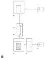
- FIG. 1 is an overall view of this embodiment.
- the apparatus is composed of a sample introduction apparatus 1, a liquid feed pump 2, a mobile phase container 3, a column thermostat 4, a column 5, a detector 6, and a waste liquid container 7, each connected by a tube.
- the configuration can be changed according to the purpose such as the number of the mobile phase containers 3 and the liquid feeding pump 2, the type of the detector 6, and the presence or absence of the column thermostat 4.
- the mobile phase in the mobile phase container 3 is fed by the liquid feed pump 2.
- An analytical sample is injected into the column 5 from the sample introduction device 1 during the liquid feeding.
- the injected sample is separated in the column 5. Since the separation is affected by the temperature, the temperature is kept constant by the column thermostat 4.
- the separated sample is detected by the detector 6 and discharged to the waste liquid container 7.
- the column is a cylindrical container that contains a solid fine particle separating agent, and has a structure having two openings at the both ends of the mobile phase inlet and outlet. In order to improve the separation performance, the solid particles are reduced, and the flow rate of the mobile phase is increased in order to shorten the separation time. Both of them work in the direction of increasing the pressure in the column.
- Disconnect the piping connection on the outlet side and inlet side of the installed column (column 1). Move column 1 3. Next, move the column to be installed (column 2) to a predetermined position (position where column 1 existed).
- An apparatus and a column for performing a series of operations of connecting the outlet side and the inlet side piping of the column 2 are provided.
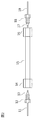
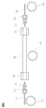
- the part configuration of the column and its connection is as shown in Fig.2.
- the column includes a column tube 15 and column ends 14 and 16 located at both ends of the column tube 15.
- the column tube 15 is filled with a packing material for separation.
- the column ends 14 and 16 are internally threaded to secure a space for receiving the ferrules 13 and 17 and part of the pipes 11 and 19.
- the column connection portion is composed of pipes 11 and 19, screws 12 and 18, and ferrules 13 and 17.
- the pipes 11 and 19 pass through the screws 12 and 18 and the ferrules 13 and 17.
- the screws 12 and 18 are divided into a holding portion and an outer screw portion, and there are through holes through which the pipes 11 and 19 pass.
- the outer threaded portion can be tightened with the inner threads of the column ends 14 and 16, and is deformed so as to seal between the pipes 11 and 19 passing through the threaded sections and the inner threads of the column ends 14 and 16.
- Ferrules 13 and 17 are parts that hold down the pipes 11 and 19, and have through holes through which the pipes 11 and 19 pass.
- a filter called a frit is mounted between the external threads of the screws 12 and 18 and the column ends 14 and 16 so that the packing material inside the column tube 15 does not leak.
- the pipes 11 to 14 are the inlet side for injecting the solution into the column
- 16 to 19 are the outlet side for discharging the solution from the column.
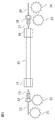
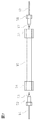
- any one of the screws 12, the column end 14 or the column end 16, and the screw 18 is a left screw.
- the relationship between the screw 12 at the inlet side connection portion and the screw 18 at the outlet side connection portion is a reverse screw relationship in which the direction in which the screw is turned and closed is reversed.
- the internal threads at the column ends at both ends of the column are reverse threads. As shown in FIG. 5, when the column end 36 and the screw 38 at the outlet side connection portion are left-handed, when removing the column, the screw 12 rotates from the lower side to the upper side and the column end 14 rotates from the upper side to the lower side.
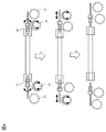
- FIG. 6 shows a schematic diagram of a motor for automating the attachment / detachment of a column. First, the column tube 15 in FIG. 6 is rotated by the motor 42, and the inlet connection portion and the outlet connection portion are fixed by a fixture or the like so as not to rotate.
- the motors 41 and 43 that move the inlet connection portion and the outlet connection portion closer to or away from the column may be used. However, if the column can be moved to the left and right, the motor 41 or 43 can be attached and detached with only one motor. In any case, the number of motors can be reduced when a counter-screw column is used at both ends of the column of FIG. 5, unlike when a right-hand screw is used at both ends of the column of FIG. Furthermore, this simplifies the device configuration and can provide a user-friendly device. In addition, the column cannot be mounted when the outlet side and the inlet side of the column are reversed by reversing the screw on the inlet side and the screw on the outlet side. Therefore, there is also an effect of preventing connection to the column by reversing the column direction. As a result, the column can always be packed from one direction, and can flow in the same direction during analysis, resulting in highly reproducible results.
- the present Example demonstrated the structure which has a thread part in a junction part and an internal thread in a column
- the structure which has a thread part in a column side and an internal thread in a junction part side may be sufficient.
- the screw thread is removed and sealing is performed with a pressing force.
- FIG. 7 when the screw thread is eliminated and the holding portion 52 and the holding portion 58 are used, the column can be attached and detached only by moving in the left-right direction.
- the attachment / detachment of the column is automated using a motor, as shown in FIG. 8, the attachment / detachment can be performed by a motor 63 that moves the outlet side holding portion 58 closer or away and a motor 62 that moves the column tube 15 left and right.
- Column 2 is fitted with a cap at the outlet and inlet during storage. Thereby, drying inside the column can be prevented.
- the column is managed individually using IC tags, microchips and barcodes.
- the peak elution position can be known more accurately, and it becomes easier to detect more than analysis.
- the column When removing the column 1, the column is removed after the internal pressure of the column is lowered by stopping the liquid phase feeding for a certain period of time. Thereby, the pressure change in the column can be alleviated and the deterioration of the column due to the sudden change in pressure can be suppressed.
- the internal pressure of the column is monitored with a pressure gauge, and the column is removed after the column pressure has dropped.
- the pressure change in the column can be reliably relaxed, and deterioration of the column due to a sudden change in pressure can be suppressed.
- the column When the column is discarded and the column is used at a temperature of 50 ° C or higher, it is not in direct contact with humans until it is guaranteed by the temperature sensor that the column temperature is lowered or left for a certain period of time. To maintain. This can prevent operator burns.
- the temperature adjustment of the column 2 to be mounted next is started before the replacement, and the conditioning time of the column after the replacement is shortened. As a result, loss of analysis time due to column exchange can be reduced.
- a device that attaches and detaches a column with one end of the column having a reverse thread It has a motor that rotates the column, and the screw on the piping side does not rotate, but is fixed so as to move in the parallel direction. With the rotation of the motor, the inlet and outlet pipes can be attached and detached simultaneously.
- a torque sensor is attached to the motor, and it has a mechanism that stops the rotation of the motor when it is squeezed with a certain strength or when it has not reached a certain strength for a certain period of time.
- a device that attaches and detaches a column with one end of the column having a reverse thread It has a motor that rotates the column, and the screw on the piping side does not rotate, but is fixed so as to move in the parallel direction. Further, when the column is mounted, the screw on the inlet side comes in contact with the screw on the outlet side to start the connection. Thereby, the connection on the inlet side is stronger than the outlet side. In HPLC analysis, pressure is generated when the mobile phase passes through the column packing, and the inlet side is exposed to a higher pressure than the outlet side. By strengthening the connection on the inlet side, the risk of liquid leakage can be reduced.
- a device that attaches and detaches a column with one end of the column having a reverse thread It has a motor that rotates the external screw on the inlet side, the column is fixed so that it moves in the parallel direction, and the screw on the outlet side is fixed so that it does not rotate or move in the parallel direction. At this time, the column can be arbitrarily set so as to rotate or not rotate. Further, when the column is mounted, the screw on the inlet side comes in contact with the screw on the outlet side to start the connection. First, the column is fixed so as not to rotate, and the inlet side is connected by rotating the screw on the inlet side. When a certain strength is reached, the column can be rotated, and the outlet side is connected by moving horizontally to the outlet side.
- connection on the outlet side is terminated with a torque lower than the rotational torque of the motor that has ended the connection on the inlet side.
- the motor connected to the external screw on the inlet side is reversely rotated while the column is rotating. Since the outlet side is tightened with a weaker torque than the inlet side, the outlet side first comes off and the column rotates idly. A state where the torque is weaker than a certain value for a certain period of time is detected, and the column is fixed with a fixture or the like so as to stop the rotation of the column.
- the power of the motor is used to remove the screw on the inlet side, and by detecting that the torque is weaker than a certain value for a certain period of time, it is detected that the column has been removed and the motor is stopped. .
Abstract
本発明はより簡易にカラムを交換するためのカラム交換装置及びそれに適したカラムを提供するものである。 本発明の構成は、両端に内ねじを有するカラムと、前記カラムの端を固定する第一の接合部と、第二の接合部を備えるカラム交換機構であって、前記第一の接合部と第二の接合部は前記カラムの端と接合するネジ部を備え、前記第一の接合部が有するネジ部のネジを回すと閉まる方向と、前記第二の接合部が有するネジ部のネジを回すと閉まる方向は、逆方向であることを特徴とするカラム交換機構である。
Description
本発明はカラム交換装置、及びそれに適したカラムを提供する。
液体クロマトグラフィー(LC)は、食品、化学、製薬、臨床化学などの分野において広く利用されている分析装置である。この液体クロマトグラフィーは液体の移動相中に混在する分析対象と夾雑物を固体表面との相互作用の程度の違いを利用し、分離する装置である。性能を高めた液体クロマトグラフィーとして、高速液体クロマトグラフィー(High-performance liquid chromatography, HPLC)や超高速液体クロマトグラフィー(Ultra High-performance liquid chromatography, UHPLC)がある。これらの装置ではカラムに数MPaから100MPa以上の圧力がかかる。特許文献1では、この圧力に耐えるためにカラムはねじ込み方式で接合されている。エンドフィッティングとカラムボディとのねじ部には、カラムボディに雄ねじが切ってあり、エンドフィッティングに切られた雌ねじと直接的に接合している。また、エンドフィッティングには、カラムボディとの反対側に、配管に接続するためのねじ部としての雌ねじが切られている。
さらに、HPLCでは、分離対象やカラム固体の変化などにより、カラム交換が必要となる。
近年、HPLCにおけるカラム交換を手締め式とする部品も出てきたが、カラム交換の際はチューブとカラムの間に隙間ができない様に注意をして取り付ける必要がある。カラムを交換するにはスパナ等の工具を用いて、取り外すカラムのネジを外し、取りつけるカラムのネジを締めることにより行う。HPLCは操作やデータ処理に専門性が必要であり、その様な操作者にとってカラム交換の操作は特に難しいものではなかった。しかし、上述した通りカラム取り付け時はチューブとカラムの間に隙間ができない様注意が必要であるため、特許文献1のようなカラムを交換するにはカラムボディを固定し、カラムボディの両端の片側ずつ順々に取り外す必要があった。
HPLCの長時間連続運転などでカラム交換を自動的に行うことが必要になった場合には、バルブにより流路を切り替える方法がとられる。2流路6方バルブを用いると2本のカラムが、1流路6方バルブを用いると6本のカラムが交換できる。しかしバルブを使う方法では、交換できるカラムの数が制限され、またバルブを通ることにより分離能の低下が問題となる。
本発明はより簡易にカラムを交換するためのカラム交換装置及びそれに適したカラムを提供するものである。
本発明の構成は、両端に内ねじを有するカラムと、前記カラムの端を固定する第一の接合部と、第二の接合部を備えるカラム交換機構であって、前記第一の接合部と第二の接合部は前記カラムの端と接合するネジ部を備え、前記第一の接合部が有するネジ部のネジを回すと閉まる方向と、前記第二の接合部が有するネジ部のネジを回すと閉まる方向は、逆方向であることを特徴とするカラム交換機構である。
本発明によれば、カラム交換作業が軽減でき、長時間の運転が可能となるという効果がある。さらに、カラム交換を自動化する際に簡易な装置構成でカラム交換を自動化することができる。
以下図面を用いて本発明の実施例を説明する。
図1は本実施例の全体図である。装置は試料導入装置1、送液ポンプ2、移動相容器3、カラム恒温槽4、カラム5、検出器6、廃液容器7より構成され、それぞれチューブによりつながれている。移動相容器3や送液ポンプ2の数、検出器6の種類、カラム恒温槽4の有無など目的により構成に変更可能である。まず、移動相容器3中の移動相を、送液ポンプ2にて送液する。送液中に試料導入装置1より分析試料がカラム5に注入される。注入された試料はカラム5にて分離される。分離は温度に影響されるので、カラム恒温槽4により一定温度に保つ。分離された試料は検出器6で検出され、廃液容器7に排出される。検出器6は、紫外可視光分光光度計、ダイオードアレー検出器、蛍光検出器、質量分析装置などがある。カラムは円柱状の容器で中に固体微粒子の分離剤が入っており、移動相の入口と出口の2つの開口部をその両端に持つ構造となっている。分離性能を上げるためには、固体粒子を小さくすることが行われ、分離時間を短くするために移動相の流速を上げることが行われるが、何れもカラムでの圧力を上昇させる方向に働く。ネジ式カラムを自動に交換するための、1.取り付けてあるカラム(カラム1)の出口側と入口側の配管接続を外す 2.カラム1を移動させる 3.次に取りつけるカラム(カラム2)を所定の位置(カラム1が存在していた位置)に移動する 4.カラム2の出口側と入口側の配管を接続する という一連の動作を行う装置及びカラムを提供する。
カラム及びその接続部の部品構成は図2の様になっている。カラムはカラム管15と、カラム管15の両端に位置するカラムエンド14、16、から構成されている。カラム管15の中には、分離を担う充填剤が充填されている。カラムエンド14、16には内ネジが切ってあり、フェラル13、17と配管11、19の一部が入る空間が確保されている。カラムの接続部は配管11、19と、ネジ12、18と、フェラル13、17から構成される。配管11、19はネジ12、18、及びフェラル13、17の内部を通り抜けている。ネジ12、18は保持部と外ネジ部に分かれており、内部には配管11、19が通る貫通孔がある。外ネジ部はカラムエンド14、16の内ねじと締め付け合うことができ、ネジ部の内部を通っている配管11、19とカラムエンド14、16の内ネジの間を密封する様に変形する。フェラル13、17は、配管11、19を押さえつける部品であり、内部に配管11、19が通る貫通孔がある。カラム管15の内部の充填剤が漏れない様に、ネジ12、18の外ネジと、カラムエンド14、16の間にはフリットと呼ばれるフィルターが装着されている。本実施例では配管11から14をカラムに溶液を注入する入口側、16から19をカラムから溶液を出す出口側とする。
ネジは全て右ネジが一般的である。即ち、ネジ12、18に右ねじを用いた場合は、カラムを外す時にネジ12は手前側下から上へ、カラムエンド14は手前側上から下へ回転し、カラムエンド16は手前側下から上へ、ネジ18は手前側上から下へ回転する動作となる。カラムをつける時にはこの逆の回転となる。ネジ12とカラムエンド14、カラムエンド16とネジ18はそれぞれ双方が動いても良いし、どちらか一方、例えばカラムエンド14は固定しネジ12のみが動いても良い。カラムエンド14とカラムエンド16は逆回転となるが、一体化しているので入口側と出口側を同時に外す、若しくはつける動作はできない。カラムを回転させると、入口側を外す若しくはつける時に出口側の配管にねじれが生じる。従って、モーターを用いてカラム着脱の動作を自動化しようとすると、図3の様にカラム管15を固定し、ネジ12及びネジ18を逆に回転させるモーター22及びモーター23と、ネジ12及びネジ18をカラムに接近させる若しくは引き離すモーター21及びモーター24を備える必要がある。ここで図4を用いて、カラム着脱のフローを説明する。カラムを接続部から外すときは、まずネジ12、18を、モーター22、23を用いて回転させて外す。ここで、ネジ12、18が何れも右ねじだった場合は、外すために回転させる方向が異なるため、ネジの片方ずつ外さなければならない。次に、モーター21、24を用いて、入口側接続部と出口側接続部をカラムから引き離す。このフローによって、カラムを接続部から取り外すことができる。なお、カラムを接続部に着ける場合は、図4の図を下から上に実施する。まず、モーター21及びモーター24を用いて、入口側接続部と出口側接続部をカラムにつける。次に、ネジ12、18を、モーター22、23を用いて回転させて締める。
ここで、本実施例の一つの形態ではネジ12、カラムエンド14若しくはカラムエンド16、ネジ18何れか一方のネジを左ネジとする。つまり、入り口側接続部のネジ12と出口側接続部のネジ18の関係を、ネジを回して閉まる方向が逆方向となる逆ねじの関係とする。さらに、カラムの両端のカラムエンドにある内ねじを逆ねじとする。図5に示す様に出口側接続部のカラムエンド36、ネジ38を左ネジとした場合、カラムを外す時にネジ12は手前側下から上へ、カラムエンド14は手前上側から下へ回転し、カラムエンド36は手前側上から下へ、ネジ38は手前側下から上へ回転する動作となる。カラムをつける時にはこの逆の回転となる。カラムの両端のカラムエンド14とカラムエンド36は着脱それぞれ同じ回転になり、カラムは手前上側から下へ回転し、ネジ12及びネジ38を回転させない様に固定すれば、入口側と出口側を同時に外すモーター1つによって容易にカラムの取り外しを実施することができる。図6にカラムの着脱を自動化する際のモーターの概略図を示す。まず、図6のカラム管15をモーター42で回転させ、入口接続部および出口接続部は回転しない様に固定具等で固定する。入口接続部および出口接続部をカラムに接近若しくは離すモーター41、43を用いても良いが、カラムが左右に移動できる様にすれば、モーター41若しくは43一方のモーターのみで脱着が可能となる。いずれにしても図3のカラムの両端に右ネジを用いるときと異なり、図5のカラムの両端に逆ねじカラムを用いるときはモーターの数を減らすことができる。さらに、これによって装置構成が簡易になり、ユーザーが使いやすい装置を提供することができる。また入口側のネジと出口側のネジを逆にすることにより、カラムの出口側・入口側を逆に置いた場合にはカラムは装着できない。従って、カラム方向を逆にしてカラムに接続することを防止する効果もある。これによって、カラムを常に一方向より充填することができ、分析時に同じ方向に流すことができ、再現性が高い結果が得られる。
なお、本実施例では接合部にネジ部を、カラムに内ねじを有する構成を説明したが、カラム側にネジ部を接合部側に内ねじを有する構成でもよい。
本実施例の別の形態ではネジのネジ山を無くし、押し付ける力でシールするものである。図7に示す様にネジのネジ山を無くし保持部52、保持部58とした場合、カラムの着脱は左右方向のみの移動で良くなる。モーターを用いてカラムの着脱を自動化しようとすると図8の様に、出口側の保持部58を近づける若しくは離すモーター63と、カラム管15を左右に移動させるモーター62で脱着が可能となる。
この時カラム交換が正しく行われたことを確認するため、以下の付加機能を加えることができる。
カラム2には保管中出口と入口にキャップを装着する。これによって、カラム内部の乾燥を防ぐことができる。
カラム交換時にカラム1のネジが固着し外れないなどの原因で、カラム1が所定の移動をしないことを検知し、警告を表示する。これによって操作者が適切に装置の不具合を把握し、処理をスムースに行うことができる。
カラム交換後にカラム2が一定圧力に到達しない場合は、カラムの接続が正しく行われないとして、送液ポンプを停止させる。この場合カラム接続部から移動相が漏れている場合が多いので、正しく分析が行われないことを防止する共に、移動相による装置の汚染を防ぐことができる。
更に、ポンプ停止後、再度カラム2を外す、取り付ける動作を繰り返す。これによって、自動的に復旧し分析を継続することができる。
カラム交換後にリークセンサ―が作動した場合は、カラムの接続が正しく行われないとして、ポンプを停止させる。
更に、ポンプ停止後、再度カラム2を外す、取り付ける動作を繰り返す。これによって、自動的に復旧し分析を継続することができる。
カラムにはICタグ、マイクロチップやバーコードなどによりカラムの個体管理を行う。これによって前回のデータを参照することで、ピーク溶出位置をより正確に知ることができ、分析以上を感知し易くなる。
取り付けられたカラム2に使用した履歴がある場合には、その使用圧力を基準とした一定の範囲内に入っていない場合、警告を表示する。
取り付けられたカラム2に使用した履歴が無い場合には、そのカラム種類及びカラムサイズなどより設定された圧力範囲データを参照し、一定の範囲内に入っていない場合、警告を表示する。これによってカラムの異常を早期に検知し、誤った分析データを提示することを防ぎ、また誤分析による時間の損失を減らす。
カラム2を取り付けた後、一定時間移動相を流した後に、規定の分析化合物を分析し、分析結果が仕様に入ることを確認する。これによってカラムの異常を早期に検知し、誤った分析データを提示することを防ぎ、また誤分析による時間の損失を減らす。
更に、仕様外の場合には再度他のカラムに交換する。これによって、自動的に復旧し分析を継続することができる。
圧力が規定値より高くなったためにカラム交換を行い、カラム交換後においても規定値より高くなった場合、カラム以外の流路が詰った等装置の保守が必要な旨を警告、表示する。これによって操作者が適切に装置の不具合を把握し、処理をスムースに行うことができる。
取り付けたカラム2が一定温度に達したことを確認、もしくは一定温度に達した後に一定時間その温度を維持していることを確認した後に分析を開始する。これによって溶出の再現性が良くなる。
カラム1を外す時には移動相の送液を停止した後に一定時間を置くことにより、カラム内圧が低下した後にカラムを外す。これによって、カラム内の圧力変化を緩和でき、圧力の急変によるカラムの劣化を抑制できる。
更にこのとき、カラム内圧を圧力計にてモニタリングし、カラム圧力が低下した後にカラムを外す。これによって、カラム内の圧力変化の緩和を確実に行え、圧力の急変によるカラムの劣化を抑制できる。
カラムはICタグやバーコードなどにより個体管理され、外されたカラムが分析結果より再使用可能と判断されている場合にはカラムを保管し、再使用不可と判断されて外された場合は廃棄される。これによって、カラムの再利用が促進される。
更に、再使用可能と判断されたカラムに対して、カラムの出口と入口にキャップを装着する機能。これによって、カラムの乾燥による劣化を抑制することができる。
カラムを廃棄する場合でかつカラムが50℃以上の温度で使用されていた場合、カラムの温度が低下することを温度センサで検知若しくは一定時間放置することにより担保するまで、人が直接触れない状態を維持する。これによって、操作者の火傷を防ぐことができる。
使用中のカラム1の性能が低下し、仕様を外れることが予想される場合に、次に取り付けられるカラム2の温度調節を交換前に開始し、交換後のカラムのコンディショニング時間を短縮する。これによって、カラム交換による分析時間の損失を減ずることができる。
分析シークエンスによりカラム交換が予定される場合に、次に取り付けられるカラム2の温度調節を交換前に開始し、交換後のカラムのコンディショニング時間を短縮する。これによって、カラム交換による分析時間の損失を減ずることができる。
液体クロマトグラフィーにおいて1.取り付けてあるカラム(カラム1)の出口側と入口側の配管接続を外す 2.カラム1を移動させる 3.次に取りつけるカラム(カラム2)を所定の位置(カラム1が存在していた位置)に移動する 4.カラム2の出口側と入口側の配管を接続する という一連の動作を自動的に行う装置。
液体クロマトグラフィーでネジにより接続しているカラムを使用している場合において1.取り付けてあるカラム(カラム1)の出口側と入口側の配管のネジを外す 2.カラム1を移動させる 3.次に取りつけるカラム(カラム2)を所定の位置(カラム1が存在していた位置)に移動する 4.カラム2の出口側と入口側の配管のネジを締めて接続する という一連の動作を自動的に行う装置。図に示す様にカラムの出口側と入口側には、それぞれ接続配管のネジを回すモーターと、接続配管をカラムに近付ける/離すためのモーターを有し、カラム1とカラム2を交換するため、カラム1とカラム2を移動するモーターの計5個のモーターにより、この動作を行う。
液体クロマトグラフィーでネジにより接続しているカラムを使用している場合において、更にカラムの両端のネジが右ネジと左ネジである場合において、1.取り付けてあるカラム(カラム1)の出口側と入口側の配管のネジを外す 2.カラム1を移動させる 3.次に取りつけるカラム(カラム2)を所定の位置(カラム1が存在していた位置)に移動する 4.カラム2の出口側と入口側の配管のネジを締めて接続する という一連の動作を自動的に行う装置。図に示す様にカラムの出口側と入口側には、カラムを回すモーターと、接続配管をカラムに近付ける/離すためのモーターを有し、カラム1とカラム2を交換するため、カラム1とカラム2を移動するモーターの計3個のモーターにより、この動作を行う。
液体クロマトグラフィーで圧着により接続しているカラムを使用している場合において1.取り付けてあるカラム(カラム1)の出口側と入口側に接続している配管を、移動させることにより接続を解く 2.カラム1を移動させる 3.次に取りつけるカラム(カラム2)を所定の位置(カラム1が存在していた位置)に移動する 4.カラム2の出口側と入口側の配管を圧着することにより接続する という一連の動作を自動的に行う装置。図に示す様にカラムの片側に、接続配管をカラムに近付ける/離すためのモーターを有し、カラム1とカラム2を交換するため、カラム1とカラム2を移動するモーターとの計2個のモーターにより、この動作を行う。
カラムの一端が逆ネジになったカラムを着脱する装置。カラムを回転させるモーターを有し、配管側のネジは回転せず、但し平行方向には動くように固定してある。モーターの回転により、入口側と出口側の配管が同時に着脱できる。モーターにはトルクセンサーをつけ、一定の強さで絞められた時、若しくは一定時間一定の強さに達しなかった時には着脱が終了したとして、モーターの回転を停止する機構を有する。
カラムの一端が逆ネジになったカラムを着脱する装置。カラムを回転させるモーターを有し、配管側のネジは回転せず、但し平行方向には動くように固定してある。さらにカラム装着をする時に、入口側のネジが、出口側のネジより先に接触し接続を開始する様に設定してある。これにより、入口側の接続の方が出口側よりも強くなる。HPLC分析では移動相がカラム充填剤を通る時に圧力が生じ、入口側の方が出口側よりも高圧にさらされる。入口側の接続を強くすることにより、液漏れのリスクを減少させることができる。
カラムの一端が逆ネジになったカラムを着脱する装置。入口側の外ネジを回転させるモーターを有し、カラムは平行方向には動くように固定してあり、出口側のネジは回転も平行方向への移動もしない様に固定してある。この時、カラムは回転する若しくはしない様に任意に設定できる。さらにカラム装着をする時に、入口側のネジが、出口側のネジより先に接触し接続を開始する様に設定してある。まずカラムは回転しない様に固定してあり、入口側のネジが回転することにより入口側が接続される。一定の強さに達した時、カラムの回転をできるようにし、出口側へ水平移動することにより、出口側の接続を行う。出口側の接続の終了は、入口側の接続を終了したモーターの回転トルクよりも低いトルクで終了とする。カラムを外すときには、カラムは回転する状態で入口側外ネジに接続したモーターを逆回転させる。出口側の方が入口側よりも弱いトルクで締めつけてあるため、まず出口側が外れ、カラムが空回転する。一定時間トルクが一定値よりも弱い状態を感知し、カラムの回転を停止するよう固定具等で固定する。これにより、モーターの力は入口側のネジを外すのに用いられ、一定時間トルクが一定値よりも弱い状態を感知することにより、カラムを外すことが終了したことを感知し、モーターを停止する。
Claims (14)
- 両端に内ねじを有するカラムと、
前記カラムの端を固定する第一の接合部と、第二の接合部を備えるカラム交換機構であって、
前記第一の接合部と第二の接合部は前記カラムの端と接合するネジ部を備え、
前記第一の接合部が有するネジ部のネジを回すと閉まる方向と、前記第二の接合部が有するネジ部のネジを回すと閉まる方向は、逆方向であることを特徴とするカラム交換機構。 - 請求項1記載のカラム交換機構において、
前記カラムの両端が有する内ねじの関係は、ネジを回すと閉まる方向が逆となることを特徴とするカラム交換機構。 - 請求項2記載のカラム交換機構において、
さらに前記カラムを回転させるモーターと、
前記第一の接合部および/または第二の接合部を固定する固定具と、
を備えることを特徴とするカラム交換機構。 - 請求項3記載のカラム交換機構において、
さらに、前記第一の接合部および/または第二の接合部を前記カラムに近付けるモーターを備えることを特徴とするカラム交換機構。 - 請求項4記載のカラム交換機構において、
前記カラムに装着するキャップを備えることを特徴とするカラム交換機構。 - 請求項4記載のカラム交換機構において、
カラム交換時にカラムから前記第一の接合部および/または第二の接合部が固着し外れない場合、警告を表示することを特徴とするカラム交換機構。 - 請求項4記載のカラム交換機構において、
カラム交換後にカラム内の圧力が一定圧力に到達しない場合は、送液ポンプを停止させることを特徴とするカラム交換機構。 - 請求項4記載のカラム交換機構において、
カラムに識別良識を付し、前回のカラムのデータを参照することを特徴とするカラム交換機構。 - 請求項8記載のカラム交換機構において、
カラムに使用した履歴がある場合には、その使用圧力を基準とした一定の範囲内に入っていない場合、警告を表示することを特徴とするカラム交換機構。 - 請求項8記載のカラム交換機構において、
カラムに使用した履歴が無い場合には、そのカラム種類及びカラムサイズなどより設定された圧力範囲データを参照し、一定の範囲内に入っていない場合、警告を表示することを特徴とするカラム交換機構。 - 請求項4記載のカラム交換機構において、
カラム内の温度が一定温度に達したことを確認、もしくは一定温度に達した後に一定時間その温度を維持していることを確認した後に分析を開始することを特徴とするカラム交換機構。 - 請求項4記載のカラム交換機構において、
カラム内圧を圧力計にてモニタリングし、カラム圧力が低下した後にカラムを外すことを特徴とするカラム交換機構。 - 請求項8記載のカラム交換機構において、
外されたカラムが分析結果より再使用可能と判断されている場合にはカラムを保管し、再使用不可と判断されて外された場合は廃棄することを特徴とするカラム交換機構。 - 請求項8記載のカラム交換機構において、
使用中のカラムの性能が低下し、仕様を外れることが予想される場合に、次に取り付けられるカラムの温度調節を交換前に開始することを特徴とするカラム交換機構。
Priority Applications (5)
| Application Number | Priority Date | Filing Date | Title |
|---|---|---|---|
| JP2018557474A JP6867407B2 (ja) | 2016-12-22 | 2016-12-22 | カラム及び交換装置 |
| US16/472,587 US20190317061A1 (en) | 2016-12-22 | 2016-12-22 | Column and exchange device |
| EP16924672.5A EP3561505A4 (en) | 2016-12-22 | 2016-12-22 | COLUMN AND REPLACEMENT DEVICE |
| CN201680091728.7A CN110088614B (zh) | 2016-12-22 | 2016-12-22 | 色谱柱及更换装置 |
| PCT/JP2016/088272 WO2018116432A1 (ja) | 2016-12-22 | 2016-12-22 | カラム及び交換装置 |
Applications Claiming Priority (1)
| Application Number | Priority Date | Filing Date | Title |
|---|---|---|---|
| PCT/JP2016/088272 WO2018116432A1 (ja) | 2016-12-22 | 2016-12-22 | カラム及び交換装置 |
Publications (1)
| Publication Number | Publication Date |
|---|---|
| WO2018116432A1 true WO2018116432A1 (ja) | 2018-06-28 |
Family
ID=62627019
Family Applications (1)
| Application Number | Title | Priority Date | Filing Date |
|---|---|---|---|
| PCT/JP2016/088272 WO2018116432A1 (ja) | 2016-12-22 | 2016-12-22 | カラム及び交換装置 |
Country Status (5)
| Country | Link |
|---|---|
| US (1) | US20190317061A1 (ja) |
| EP (1) | EP3561505A4 (ja) |
| JP (1) | JP6867407B2 (ja) |
| CN (1) | CN110088614B (ja) |
| WO (1) | WO2018116432A1 (ja) |
Cited By (3)
| Publication number | Priority date | Publication date | Assignee | Title |
|---|---|---|---|---|
| JP7058402B1 (ja) | 2021-02-26 | 2022-04-22 | 株式会社プレッパーズ | 液体クロマトグラフ用ノズル及び液体クロマトグラフ |
| WO2022224539A1 (ja) * | 2021-04-22 | 2022-10-27 | 株式会社日立ハイテク | クロマトグラフ |
| WO2022224540A1 (ja) * | 2021-04-23 | 2022-10-27 | 株式会社日立ハイテク | 分析装置及び分析装置の制御方法 |
Families Citing this family (2)
| Publication number | Priority date | Publication date | Assignee | Title |
|---|---|---|---|---|
| GB2603139B (en) * | 2021-01-27 | 2024-01-10 | Agilent Technologies Inc | Mounting a sample separation unit by a swivel mechanism |
| CN117108836B (zh) * | 2023-10-24 | 2024-03-29 | 劢析科学仪器(苏州)有限公司 | 微流量流体连接系统及其管路的连接装置 |
Citations (12)
| Publication number | Priority date | Publication date | Assignee | Title |
|---|---|---|---|---|
| JPS58184388A (ja) * | 1982-03-03 | 1983-10-27 | ブラウンリイ・ラブス・インコ−ポレイテツド | 高圧シ−ル・カツプリング |
| JPS59144887A (ja) * | 1983-02-04 | 1984-08-20 | 川崎製鉄株式会社 | 耐食二重管の接続構造 |
| JPS61154561U (ja) * | 1985-03-15 | 1986-09-25 | ||
| JPH02238363A (ja) * | 1989-03-13 | 1990-09-20 | Meidensha Corp | 生化学分析機のカラムとその装着装置 |
| JPH0355984U (ja) * | 1989-10-05 | 1991-05-29 | ||
| JPH0478554U (ja) * | 1990-11-21 | 1992-07-08 | ||
| WO2001006166A2 (en) * | 1999-07-19 | 2001-01-25 | Neogenesis, Inc. | Linear motion compression connector |
| US20070084982A1 (en) * | 2005-10-17 | 2007-04-19 | Agilent Technologies, Inc. | Holding device for chromatograph columns |
| JP2007199041A (ja) * | 2005-05-24 | 2007-08-09 | Hellermann Tyton Co Ltd | カートリッジカラム |
| US20100154207A1 (en) * | 2008-12-23 | 2010-06-24 | Optimize Technologies, Inc. | Assembly for placing an insert into communication with an analytical chemical instrument |
| JP2014095700A (ja) * | 2012-11-12 | 2014-05-22 | Dionex Corp | ゼロ死空間の頑強な流体接続システム |
| WO2014080925A1 (ja) * | 2012-11-21 | 2014-05-30 | 株式会社日立ハイテクノロジーズ | 配管連結継手 |
Family Cites Families (7)
| Publication number | Priority date | Publication date | Assignee | Title |
|---|---|---|---|---|
| DE3045654C2 (de) * | 1980-12-04 | 1985-03-28 | Carlo Erba Strumentazione S.p.A., Rodano, Milano | Vorrichtung zum Verbinden von pneumatischen und/oder hydraulischen Kreisen in der Trenntechnik |
| JPH11174036A (ja) * | 1997-12-08 | 1999-07-02 | Sekisui Chem Co Ltd | 液体クロマトグラフィー用カラム |
| US6193286B1 (en) * | 1998-02-27 | 2001-02-27 | Selerity Technologies Inc. | Device and method for connecting a fluid conduit to a receiving fitting |
| WO2008060784A2 (en) * | 2006-10-05 | 2008-05-22 | Affinex, Llc | System for rapid analysis of glycated proteinaceous species in biological samples |
| CN201249280Y (zh) * | 2007-03-28 | 2009-06-03 | 江苏省无锡建华机床厂 | 自定心卡盘 |
| CN103055541B (zh) * | 2012-08-31 | 2015-02-18 | 常州三泰科技有限公司 | 建立和使用网络化的分离纯化方法数据库的方法及其仪器 |
| CN104897817B (zh) * | 2015-06-18 | 2017-03-01 | 常州三泰科技有限公司 | 色谱仪以及重复使用色谱柱的方法 |
-
2016
- 2016-12-22 WO PCT/JP2016/088272 patent/WO2018116432A1/ja unknown
- 2016-12-22 US US16/472,587 patent/US20190317061A1/en not_active Abandoned
- 2016-12-22 CN CN201680091728.7A patent/CN110088614B/zh active Active
- 2016-12-22 EP EP16924672.5A patent/EP3561505A4/en active Pending
- 2016-12-22 JP JP2018557474A patent/JP6867407B2/ja active Active
Patent Citations (12)
| Publication number | Priority date | Publication date | Assignee | Title |
|---|---|---|---|---|
| JPS58184388A (ja) * | 1982-03-03 | 1983-10-27 | ブラウンリイ・ラブス・インコ−ポレイテツド | 高圧シ−ル・カツプリング |
| JPS59144887A (ja) * | 1983-02-04 | 1984-08-20 | 川崎製鉄株式会社 | 耐食二重管の接続構造 |
| JPS61154561U (ja) * | 1985-03-15 | 1986-09-25 | ||
| JPH02238363A (ja) * | 1989-03-13 | 1990-09-20 | Meidensha Corp | 生化学分析機のカラムとその装着装置 |
| JPH0355984U (ja) * | 1989-10-05 | 1991-05-29 | ||
| JPH0478554U (ja) * | 1990-11-21 | 1992-07-08 | ||
| WO2001006166A2 (en) * | 1999-07-19 | 2001-01-25 | Neogenesis, Inc. | Linear motion compression connector |
| JP2007199041A (ja) * | 2005-05-24 | 2007-08-09 | Hellermann Tyton Co Ltd | カートリッジカラム |
| US20070084982A1 (en) * | 2005-10-17 | 2007-04-19 | Agilent Technologies, Inc. | Holding device for chromatograph columns |
| US20100154207A1 (en) * | 2008-12-23 | 2010-06-24 | Optimize Technologies, Inc. | Assembly for placing an insert into communication with an analytical chemical instrument |
| JP2014095700A (ja) * | 2012-11-12 | 2014-05-22 | Dionex Corp | ゼロ死空間の頑強な流体接続システム |
| WO2014080925A1 (ja) * | 2012-11-21 | 2014-05-30 | 株式会社日立ハイテクノロジーズ | 配管連結継手 |
Non-Patent Citations (1)
| Title |
|---|
| See also references of EP3561505A4 * |
Cited By (4)
| Publication number | Priority date | Publication date | Assignee | Title |
|---|---|---|---|---|
| JP7058402B1 (ja) | 2021-02-26 | 2022-04-22 | 株式会社プレッパーズ | 液体クロマトグラフ用ノズル及び液体クロマトグラフ |
| JP2022131302A (ja) * | 2021-02-26 | 2022-09-07 | 株式会社プレッパーズ | 液体クロマトグラフ用ノズル及び液体クロマトグラフ |
| WO2022224539A1 (ja) * | 2021-04-22 | 2022-10-27 | 株式会社日立ハイテク | クロマトグラフ |
| WO2022224540A1 (ja) * | 2021-04-23 | 2022-10-27 | 株式会社日立ハイテク | 分析装置及び分析装置の制御方法 |
Also Published As
| Publication number | Publication date |
|---|---|
| JPWO2018116432A1 (ja) | 2019-10-24 |
| CN110088614B (zh) | 2022-06-24 |
| EP3561505A4 (en) | 2020-08-26 |
| EP3561505A1 (en) | 2019-10-30 |
| US20190317061A1 (en) | 2019-10-17 |
| CN110088614A (zh) | 2019-08-02 |
| JP6867407B2 (ja) | 2021-04-28 |
Similar Documents
| Publication | Publication Date | Title |
|---|---|---|
| WO2018116432A1 (ja) | カラム及び交換装置 | |
| JP5940179B2 (ja) | 接続組立体 | |
| US4476017A (en) | Removable synthesis column | |
| US8307541B2 (en) | Assembly for placing an insert into communication with an analytical chemical instrument | |
| JP2015512053A (ja) | トルク制限接続具 | |
| US8062520B2 (en) | Replaceable column for pressurized liquid extraction system | |
| US20100224543A1 (en) | Connection assembly for ultra high pressure liquid chromatography | |
| US20170248449A1 (en) | Modular Sensor System | |
| WO2012118996A1 (en) | High pressure fitting with self-releasing ferrule | |
| US20140123819A1 (en) | Torque Limiting Tool and Methods | |
| US9404785B2 (en) | Retractable assembly for immersion-, flow- and attachment-measuring systems | |
| US20230102761A1 (en) | Chromatography System and Couplings Therefor | |
| JP6329128B2 (ja) | 液体クロマトグラフィー用カラム装置及び液体クロマトグラフィー装置 | |
| JPH04211765A (ja) | 高圧密閉装置 | |
| US7901574B2 (en) | Quick disconnect liquid chromatograph columns | |
| JP2019162611A (ja) | 押出し可能な物質を表面上に堆積させるための装置及び方法 | |
| WO2012117259A2 (en) | Locking of threaded fasteners | |
| EP2502064A1 (en) | Supporting devices for capillary and nano hplc columns | |
| JP2015114293A (ja) | 液体クロマトグラフ用カラムおよび液体クロマトグラフ装置 | |
| CN220786748U (zh) | 快装取样瓶 | |
| CN213348053U (zh) | 一种用于在线过滤器的安装组件 | |
| US11085904B2 (en) | Column having a compression-limited assembly | |
| CN101389390A (zh) | 射流分散器、过滤器固定系统、喷嘴固定系统 |
Legal Events
| Date | Code | Title | Description |
|---|---|---|---|
| 121 | Ep: the epo has been informed by wipo that ep was designated in this application |
Ref document number: 16924672 Country of ref document: EP Kind code of ref document: A1 |
|
| ENP | Entry into the national phase |
Ref document number: 2018557474 Country of ref document: JP Kind code of ref document: A |
|
| NENP | Non-entry into the national phase |
Ref country code: DE |
|
| ENP | Entry into the national phase |
Ref document number: 2016924672 Country of ref document: EP Effective date: 20190722 |