WO2018110696A1 - ガスタービン制御装置、ガスタービン制御方法 - Google Patents
ガスタービン制御装置、ガスタービン制御方法 Download PDFInfo
- Publication number
- WO2018110696A1 WO2018110696A1 PCT/JP2017/045073 JP2017045073W WO2018110696A1 WO 2018110696 A1 WO2018110696 A1 WO 2018110696A1 JP 2017045073 W JP2017045073 W JP 2017045073W WO 2018110696 A1 WO2018110696 A1 WO 2018110696A1
- Authority
- WO
- WIPO (PCT)
- Prior art keywords
- value
- command value
- deviation
- gas turbine
- flow rate
- Prior art date
Links
- 238000000034 method Methods 0.000 title claims description 10
- 239000000446 fuel Substances 0.000 claims abstract description 98
- 238000004364 calculation method Methods 0.000 claims description 103
- 239000007789 gas Substances 0.000 description 77
- 238000010586 diagram Methods 0.000 description 8
- 230000006870 function Effects 0.000 description 6
- 230000007423 decrease Effects 0.000 description 4
- 239000000567 combustion gas Substances 0.000 description 3
- 238000004891 communication Methods 0.000 description 3
- 230000003247 decreasing effect Effects 0.000 description 2
- 239000002737 fuel gas Substances 0.000 description 2
- 238000004590 computer program Methods 0.000 description 1
- 238000012544 monitoring process Methods 0.000 description 1
- 239000004065 semiconductor Substances 0.000 description 1
- 230000009897 systematic effect Effects 0.000 description 1
Images
Classifications
-
- F—MECHANICAL ENGINEERING; LIGHTING; HEATING; WEAPONS; BLASTING
- F02—COMBUSTION ENGINES; HOT-GAS OR COMBUSTION-PRODUCT ENGINE PLANTS
- F02C—GAS-TURBINE PLANTS; AIR INTAKES FOR JET-PROPULSION PLANTS; CONTROLLING FUEL SUPPLY IN AIR-BREATHING JET-PROPULSION PLANTS
- F02C9/00—Controlling gas-turbine plants; Controlling fuel supply in air- breathing jet-propulsion plants
- F02C9/26—Control of fuel supply
- F02C9/263—Control of fuel supply by means of fuel metering valves
-
- F—MECHANICAL ENGINEERING; LIGHTING; HEATING; WEAPONS; BLASTING
- F02—COMBUSTION ENGINES; HOT-GAS OR COMBUSTION-PRODUCT ENGINE PLANTS
- F02C—GAS-TURBINE PLANTS; AIR INTAKES FOR JET-PROPULSION PLANTS; CONTROLLING FUEL SUPPLY IN AIR-BREATHING JET-PROPULSION PLANTS
- F02C9/00—Controlling gas-turbine plants; Controlling fuel supply in air- breathing jet-propulsion plants
- F02C9/26—Control of fuel supply
- F02C9/28—Regulating systems responsive to plant or ambient parameters, e.g. temperature, pressure, rotor speed
-
- F—MECHANICAL ENGINEERING; LIGHTING; HEATING; WEAPONS; BLASTING
- F02—COMBUSTION ENGINES; HOT-GAS OR COMBUSTION-PRODUCT ENGINE PLANTS
- F02C—GAS-TURBINE PLANTS; AIR INTAKES FOR JET-PROPULSION PLANTS; CONTROLLING FUEL SUPPLY IN AIR-BREATHING JET-PROPULSION PLANTS
- F02C9/00—Controlling gas-turbine plants; Controlling fuel supply in air- breathing jet-propulsion plants
- F02C9/16—Control of working fluid flow
- F02C9/20—Control of working fluid flow by throttling; by adjusting vanes
-
- F—MECHANICAL ENGINEERING; LIGHTING; HEATING; WEAPONS; BLASTING
- F02—COMBUSTION ENGINES; HOT-GAS OR COMBUSTION-PRODUCT ENGINE PLANTS
- F02C—GAS-TURBINE PLANTS; AIR INTAKES FOR JET-PROPULSION PLANTS; CONTROLLING FUEL SUPPLY IN AIR-BREATHING JET-PROPULSION PLANTS
- F02C9/00—Controlling gas-turbine plants; Controlling fuel supply in air- breathing jet-propulsion plants
- F02C9/26—Control of fuel supply
-
- F—MECHANICAL ENGINEERING; LIGHTING; HEATING; WEAPONS; BLASTING
- F05—INDEXING SCHEMES RELATING TO ENGINES OR PUMPS IN VARIOUS SUBCLASSES OF CLASSES F01-F04
- F05D—INDEXING SCHEME FOR ASPECTS RELATING TO NON-POSITIVE-DISPLACEMENT MACHINES OR ENGINES, GAS-TURBINES OR JET-PROPULSION PLANTS
- F05D2270/00—Control
- F05D2270/01—Purpose of the control system
- F05D2270/06—Purpose of the control system to match engine to driven device
- F05D2270/061—Purpose of the control system to match engine to driven device in particular the electrical frequency of driven generator
-
- F—MECHANICAL ENGINEERING; LIGHTING; HEATING; WEAPONS; BLASTING
- F05—INDEXING SCHEMES RELATING TO ENGINES OR PUMPS IN VARIOUS SUBCLASSES OF CLASSES F01-F04
- F05D—INDEXING SCHEME FOR ASPECTS RELATING TO NON-POSITIVE-DISPLACEMENT MACHINES OR ENGINES, GAS-TURBINES OR JET-PROPULSION PLANTS
- F05D2270/00—Control
- F05D2270/01—Purpose of the control system
- F05D2270/09—Purpose of the control system to cope with emergencies
- F05D2270/091—Purpose of the control system to cope with emergencies in particular sudden load loss
-
- F—MECHANICAL ENGINEERING; LIGHTING; HEATING; WEAPONS; BLASTING
- F05—INDEXING SCHEMES RELATING TO ENGINES OR PUMPS IN VARIOUS SUBCLASSES OF CLASSES F01-F04
- F05D—INDEXING SCHEME FOR ASPECTS RELATING TO NON-POSITIVE-DISPLACEMENT MACHINES OR ENGINES, GAS-TURBINES OR JET-PROPULSION PLANTS
- F05D2270/00—Control
- F05D2270/01—Purpose of the control system
- F05D2270/11—Purpose of the control system to prolong engine life
- F05D2270/112—Purpose of the control system to prolong engine life by limiting temperatures
-
- F—MECHANICAL ENGINEERING; LIGHTING; HEATING; WEAPONS; BLASTING
- F05—INDEXING SCHEMES RELATING TO ENGINES OR PUMPS IN VARIOUS SUBCLASSES OF CLASSES F01-F04
- F05D—INDEXING SCHEME FOR ASPECTS RELATING TO NON-POSITIVE-DISPLACEMENT MACHINES OR ENGINES, GAS-TURBINES OR JET-PROPULSION PLANTS
- F05D2270/00—Control
- F05D2270/30—Control parameters, e.g. input parameters
- F05D2270/303—Temperature
Definitions
- the present invention relates to a gas turbine control device and a gas turbine control method.
- This application claims priority based on Japanese Patent Application No. 2016-243359 filed in Japan on December 15, 2016, the contents of which are incorporated herein by reference.
- Patent Document 1 An apparatus for monitoring a gas turbine inlet temperature and controlling a gas turbine is disclosed in Patent Document 1 and Patent Document 2. If the gas turbine inlet temperature exceeds the limit value, components such as a combustor and a turbine constituting the gas turbine may be damaged. Therefore, it is necessary to control the gas turbine inlet temperature so as not to exceed the limit value.
- the generator of the power plant is driven by the gas turbine described above. Although the generator is connected to the power system, the frequency in the power system may suddenly decrease due to an increase in the load in the power system. In such a rapid frequency decrease, there is a concern that the ratio of the fuel flow rate corresponding to the gas turbine output rapidly increases and the gas turbine inlet temperature rapidly increases.
- an object of the present invention is to provide a gas turbine control device and a gas turbine control method capable of solving the above-described problems.
- the gas turbine control device sets the first fuel flow rate command value indicating the fuel input amount command value CSO (Control Signal Output) so that the output of the gas turbine matches the target output.
- CSO Control Signal Output
- the second CSO calculating unit is configured to determine whether the deviation is equal to or greater than a predetermined deviation that is determined as the estimated value of the turbine inlet temperature exceeding the first limit value.
- the upper limit value of the first fuel flow rate command value that suppresses the increase in the upper limit value of the fuel flow rate command value may be calculated.
- the second CSO calculation unit may fix the upper limit value of the first fuel flow rate command value to the currently calculated upper limit value when the deviation is equal to or greater than the predetermined deviation.
- the second CSO calculation unit may fix the upper limit value of the first fuel flow rate command value to a predetermined upper limit value when the deviation is equal to or greater than the predetermined deviation.
- the second CSO calculation unit may fix the upper limit value of the first fuel flow rate command value to a value corresponding to the deviation when the deviation is equal to or greater than the predetermined deviation.
- the gas turbine control device sets the first fuel flow rate command value indicating the fuel input amount command value CSO (Control Signal Output) so that the output of the gas turbine matches the target output.
- CSO Control Signal Output
- the deviation is calculated, and if the deviation is not equal to or greater than a predetermined deviation determined that the estimated value of the turbine inlet temperature exceeds the first limit value, the first fuel flow rate command value is included.
- a second fuel flow rate command value obtained by adding a predetermined value to the currently selected post-selection fuel flow rate command value among a plurality of fuel flow rate command values is calculated, and when the deviation is equal to or greater than the predetermined deviation, Burn after selection
- a second CSO calculation unit for calculating a second fuel command value to suppress the flow rate command value characterized in that it comprises a.
- the first CSO calculation unit indicates the fuel input amount command value CSO (Control Signal Output) so that the output of the gas turbine matches the target output.
- CSO Control Signal Output
- a first fuel flow rate command value is calculated
- a second CSO calculation unit calculates an upper limit value of the first fuel flow rate command value
- the second CSO calculation unit calculates the estimated value of the turbine inlet temperature of the gas turbine.
- an upper limit value of the first fuel flow rate command value based on a deviation obtained by subtracting a second limit value related to the estimated value set so that the estimated value does not exceed the first limit value of the turbine inlet temperature. Is calculated.
- the first CSO calculation unit indicates the fuel input amount command value CSO (Control Signal Output) so that the output of the gas turbine matches the target output.
- the first fuel flow rate command value is calculated
- the second CSO calculation unit is set from the estimated value of the turbine inlet temperature of the gas turbine so that the estimated value does not exceed the first limit value of the turbine inlet temperature.
- a second limit value related to the estimated value is subtracted, a deviation is calculated, and if the deviation is not equal to or greater than a predetermined deviation determined that the estimated value of the turbine inlet temperature exceeds the first limit value, the second limit value is calculated.
- a second fuel flow rate command value obtained by adding a predetermined value to the currently selected post-selection fuel flow rate command value among a plurality of fuel flow rate command values including one fuel flow rate command value is calculated, and the deviation is More than deviation The case and calculates a second fuel command value to suppress the selection after the fuel flow rate command value.
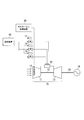
- FIG. 1 is a system diagram of a gas turbine plant according to the present embodiment.
- the gas turbine plant of the present embodiment includes a gas turbine 10, a generator 16 that generates power by driving the gas turbine 10, a gas turbine control device 20 that controls the gas turbine 10, and fuel to the gas turbine 10.
- a supply device 40 for supplying is provided.
- the gas turbine 10 and the generator 16 are connected by a rotor 15.
- the gas turbine 10 includes a compressor 11 that compresses air to generate compressed air, a combustor 12 that generates a high-temperature combustion gas by mixing and burning the compressed air and a fuel gas, a turbine 13 that is driven by the combustion gas, and the like. It is comprised including.
- the turbine inlet temperature described below indicates the temperature of the inlet at which high-temperature combustion gas ejected from the combustor 12 enters the turbine 13.
- the compressor 11 is provided with an inlet guide vane (IGV) 14.
- the IGV 14 adjusts the amount of air that flows into the compressor 11.
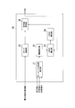
- FIG. 2 is a functional block diagram of the gas turbine control device according to the present embodiment.
- the gas turbine control device 20 is a computer and is configured by hardware such as a ROM (Read Only Memory), a RAM (Random Access Memory), a storage unit such as a hard disk drive (HDD), a CPU (Central Processing Unit), and a communication interface. It's okay.
- the CPU of the gas turbine control device 20 executes a stored control program based on a user operation.
- the gas turbine control device 20 has functions of a turbine inlet temperature estimation unit 21, a deviation calculation unit 22, an LRCSO calculation unit 23, an LDCSO calculation unit 24, a governor control unit 25, and a command value selection unit 26.
- the gas turbine control device 20 actually has functions other than the functional units illustrated in FIG. 2 by executing the control program, only the functional units illustrated in FIG. 2 will be described for convenience of explanation. And
- the turbine inlet temperature estimator 21 inputs parameters such as a plurality of measured values S1, S2, S3, and calculates an estimated value of the turbine inlet temperature using these parameters.
- the deviation calculating unit 22 calculates a deviation from the estimated value of the turbine inlet temperature by subtracting a second limit value related to the estimated value set so that the estimated value does not exceed the first limit value of the turbine inlet temperature.
- the first limit value is a value indicating that there is a possibility that damage will occur to the components constituting the turbine 13 when the turbine inlet temperature increases by more than this value.
- the second limit value is a value provided so that the turbine inlet temperature does not become equal to or higher than the first limit value, and is a limit value of the estimated value of the turbine inlet temperature.
- the LRCSO calculator 23 calculates an upper limit value of the first fuel flow rate command value calculated by the LDCSO calculator 24.
- the LRCSO calculation unit 23 calculates the upper limit value of the first fuel flow rate command value based on the deviation obtained by subtracting the second limit value from the estimated value of the turbine inlet temperature. Specifically, the LRCSO calculating unit 23 performs the LDCSO when the deviation calculated by the deviation calculating unit 22 is equal to or greater than a predetermined deviation that is determined that the estimated value of the turbine inlet temperature may exceed the first limit value.
- An upper limit value (LRCSO) of LDSCO for suppressing an increase in the upper limit value (LRCSO) of (first fuel flow rate command value) is calculated.
- the LRCSO calculation unit 23 fixes the upper limit value (LRCSO) of the LDCSO to the currently calculated upper limit value when the deviation calculated by the deviation calculation unit 22 is equal to or greater than a predetermined deviation.
- the upper limit value (LRCSO) calculated by the LRCSO calculation unit 23 is a value that rises and falls depending on each parameter related to the input gas turbine 10, and the value is fixed.
- the LRCSO calculation unit 23 may fix the upper limit value of the first fuel flow rate command value to a predetermined upper limit value when the deviation calculated by the deviation calculation unit 22 is greater than or equal to the predetermined deviation.
- the predetermined upper limit value is a fuel flow rate command value for preventing the actual turbine inlet temperature from exceeding the first limit value.
- the LRCSO calculation unit 23 may fix the upper limit value of the first fuel flow rate command value to a value corresponding to the deviation when the deviation calculated by the deviation calculation unit 22 is equal to or greater than a predetermined deviation.
- the value corresponding to the deviation is also the value of the fuel flow rate command value for preventing the actual turbine inlet temperature from exceeding the first limit value.
- the LDCSO calculation unit 24 (first CSO calculation unit) LDCSO (first fuel flow rate command value) indicating CSO (Control (Signal Output) for controlling the amount of fuel input so that the output of the gas turbine 10 matches the target output. Is calculated.
- the LDCSO calculation unit 24 calculates a CSO that does not exceed the value of LRCSO that is the upper limit value of the LDCSO calculated by the LRCSO calculation unit 23.
- the governor control unit 25 (third CSO calculation unit) inputs the frequency F of the power system to which the generator 16 is connected. Based on the frequency F, the governor control unit 25 calculates a fuel flow rate command value (CSO) that increases the output when the frequency decreases.
- CSO fuel flow rate command value
- GVSCO fuel flow rate command value
- the command value selection unit 26 compares the GVCSO acquired from the governor control unit 25 with the LDCSO acquired from the LDCSO calculation unit 24, and outputs a small value as CSO.
- the CSO is output to the control valves 17 to 19 to control the fuel flow rate.
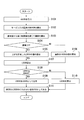
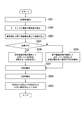
- FIG. 3 is a diagram showing a processing flow of the gas turbine control device according to the first embodiment.
- the governor control unit 25 acquires information on the frequency F of the power system.
- the governor control unit 25 inputs the value of the frequency F into the GVCSO calculation formula, and calculates GVCSO (step S101).
- the governor control unit 25 outputs the calculated GVCSO to the command value selection unit 26.
- the GVCSO calculation formula is a formula for calculating a fuel flow rate command value (CSO) based on the frequency F so as to increase the output when the frequency is decreased.
- the turbine inlet temperature estimation unit 21 acquires various parameters.
- the turbine inlet temperature estimator 21 inputs various parameters to the turbine inlet temperature estimated value calculation formula to calculate estimated values (step S102).
- the turbine inlet temperature estimating unit 21 outputs the estimated value to the deviation calculating unit 22.
- the deviation calculation unit 22 calculates the deviation by subtracting the second limit value from the estimated value (step S103).
- the deviation calculation unit 22 outputs the deviation obtained by subtracting the second limit value from the estimated value to the LRCSO calculation unit 23.
- the LRCSO calculation unit 23 determines whether the obtained deviation is 0 or more (step S104). When the deviation is 0 or more, the LRCSO calculation unit 23 performs control to suppress an increase in the value of LRCSO (step S105). When the deviation is less than 0, the LRCSO calculation unit 23 calculates a normal LRCSO value (step S106).
- the LRCSO calculation unit 23 fixes the upper limit value of LDCSO to the currently calculated LRCSO.
- the LRCSO calculating unit 23 may fix the LRCSO to a predetermined value when the deviation calculated by the deviation calculating unit 22 is 0 or more.
- the LRCSO calculation unit 23 may fix the LRCSO to a value corresponding to the deviation when the deviation calculated by the deviation calculation unit 22 is 0 or more.
- the LDCSO calculation unit 24 inputs parameters and calculates LDCSO (step S107).
- the parameters to be input are a load limit set value and a generator output.
- the LDCSO calculation unit 24 compares the load limit set value (the upper limit value or target value set for the load of the generator output) with the generator output, and performs a feedback calculation for calculating LDCSO so that the values match. Do. Further, the LDCSO calculation unit 24 acquires LRCSO.
- the LDCSO calculation unit 24 determines whether the calculated LDCSO is equal to or greater than LRCSO (step S108). If the calculated LDCSO is greater than or equal to LRCSO, the LDCSO calculation unit 24 outputs LRCSO to the command value selection unit 26 as LDCSO (step S109). When the calculated LDCSO is less than LRCSO, the LDCSO calculation unit 24 outputs the calculated LDCSO to the command value selection unit 26 (step S110).
- the command value selection unit 26 compares the GVCSO acquired from the governor control unit 25 with the LDCSO acquired from the LDCSO calculation unit 24.
- the command value selection unit 26 outputs a smaller value as a CSO between GVCSO and LDCSO (step S111).
- the CSO is output to the control valves 17 to 19 to control the fuel flow rate.
- the gas turbine control device 20 can determine whether to suppress the LRCSO value using the estimated value of the turbine inlet temperature obtained by the estimation calculation. . Therefore, even when a sudden frequency drop occurs in the power system connected to the generator 16 and the ratio of the fuel flow rate corresponding to the gas turbine output increases rapidly, an increase in LRCSO that is the upper limit value of the LDCSO is increased. Suppress. As a result, the value of CSO selected and output by the command value selection unit 26 can also be suppressed.
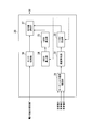
- FIG. 4 is a functional block diagram of the gas turbine control device according to the second embodiment.
- the gas turbine control device 30 is also a computer and is configured by hardware such as a ROM (Read Only Memory), a RAM (Random Access Memory), a storage unit such as a hard disk drive (HDD), a CPU (Central Processing Unit), and a communication interface. It's okay.
- ROM Read Only Memory
- RAM Random Access Memory
- HDD hard disk drive
- CPU Central Processing Unit
- the CPU of the gas turbine control device 30 executes a stored control program based on a user operation.
- the gas turbine control device 30 includes functions of the turbine inlet temperature estimation unit 31, the deviation calculation unit 32, the T1TCSO calculation unit 33, the LRCSO calculation unit 34, the LDCSO calculation unit 35, the governor control unit 36, and the command value selection unit 37. Is provided.
- the gas turbine control device 30 actually has functions other than the functional units illustrated in FIG. 4 by executing the control program, only the functional units illustrated in FIG. 4 will be described for convenience of explanation. And
- the turbine inlet temperature estimation unit 31 inputs a plurality of parameters such as measured values S1, S2, and S3, and calculates an estimated value of the turbine inlet temperature using these parameters.
- the turbine inlet temperature may be estimated using a known calculation formula.
- the deviation calculating unit 32 calculates a deviation from the estimated value of the turbine inlet temperature by subtracting a second limit value related to the estimated value set so that the estimated value does not exceed the first limit value of the turbine inlet temperature.
- the first limit value is a value indicating that there is a possibility that damage may occur in the components constituting the gas turbine 10 when the turbine inlet temperature increases by more than this value.
- the second limit value is a value provided so that the turbine inlet temperature does not become equal to or higher than the first limit value, and is a limit value of the estimated value of the turbine inlet temperature.
- the T1TCSO calculation unit 33 selects a predetermined fuel flow rate command value selected and output by the command value selection unit 37.
- T1TCSO (second fuel flow rate command value) with the value added is calculated.
- the T1TCSO calculating unit 33 calculates T1TCSO (second fuel command value) that suppresses the fuel flow rate command value CSO after selection when the deviation is equal to or greater than a predetermined deviation.
- the LRCSO calculation unit 34 calculates an upper limit value of LDCSO (first fuel flow rate command value) calculated by the LDCSO calculation unit 35.
- the LDCSO calculation unit 35 (first CSO calculation unit in the second embodiment) is an LDCSO (first control signal output) indicating CSO (Control Signal Output) for controlling the fuel input amount so that the output of the gas turbine 10 matches the target output. Fuel flow command value) is calculated.
- the LDCSO calculation unit 35 calculates a CSO that does not exceed the value of LRCSO that is the upper limit value of the LDCSO calculated by the LRCSO calculation unit 34.
- the governor control unit 36 (third CSO calculation unit) inputs the frequency F of the power system to which the generator 16 is connected. Based on the frequency F, the governor control unit 36 calculates a fuel flow rate command value (CSO) that increases the output when the frequency decreases.
- CSO fuel flow rate command value
- GVSCO fuel flow rate command value
- the command value selection unit 37 compares the GVCSO acquired from the governor control unit 36, the LDCSO acquired from the LDCSO calculation unit 35, and the T1TCSO acquired from the T1TCSO calculation unit 33, and outputs a smaller value as CSO.
- the CSO is output to the control valves 17 to 19 to control the fuel flow rate.
- FIG. 5 is a diagram showing a processing flow of the gas turbine control device according to the second embodiment.
- the governor control unit 36 acquires information on the frequency F of the power system.
- the governor control unit 36 inputs the value of the frequency F into the GVCSO calculation formula, and calculates GVCSO (step S201).
- the governor control unit 36 outputs the calculated GVCSO to the command value selection unit 37.
- the GVCSO calculation formula is a formula for calculating a fuel flow rate command value (CSO) based on the frequency F so as to increase the output when the frequency is decreased.
- the turbine inlet temperature estimation unit 31 acquires various parameters.
- the turbine inlet temperature estimation unit 31 inputs various parameters to the estimated value calculation formula for the turbine inlet temperature T1T to calculate an estimated value (step S202).
- the turbine inlet temperature estimation unit 31 outputs the estimated value to the deviation calculation unit 32.
- the deviation calculation unit 32 calculates the deviation by subtracting the second limit value from the estimated value (step S203). That is, the deviation calculated by the deviation calculation unit 32 is a second limit value related to an estimated value set so that the estimated value does not exceed the first limit value of the turbine inlet temperature from the estimated value of the turbine inlet temperature T1T. This is the reduced value.
- the deviation calculation unit 32 outputs the calculated deviation to the T1TCSO calculation unit 33.
- an estimated value may be calculated using a known calculation formula.
- the T1TCSO calculation unit 33 determines whether the acquired deviation is 0 or more (step S204). When the acquired deviation is less than 0, the T1TCSO calculation unit 33 acquires various parameters and the CSO selected and output by the command value selection unit 37 in the T1TCSO calculation formula, and T1TCSO having a value larger than the CSO. Is calculated (step S205). Further, when the obtained deviation is 0 or more, the T1TCSO calculation unit 33 calculates T1TCSO that suppresses the CSO selected and output by the command value selection unit 37 (step S206). The T1TCSO calculation unit 33 outputs the calculated T1TCSO to the command value selection unit 37.
- the T1TCSO calculation unit 33 calculates, for example, a value obtained by multiplying the CSO by a rate limiter (the rate of change of the CSO, particularly the increase rate) from the moment when the deviation exceeds 0, and outputs it as T1TCSO. To do. More specifically, the T1TCSO calculation unit 33 outputs the value of the last input CSO value as a fixed value so that the rate of change in CSO increase is 0, for example, so that the value of T1TCSO is obtained. Set so that it does not increase any further.
- a rate limiter the rate of change of the CSO, particularly the increase rate
- the LRCSO calculation unit 34 calculates an upper limit value (LRCSO) of LDCSO indicating a value obtained by adding a predetermined bias value or the like to the CSO selected and output by the command value selection unit 37 (step S207).
- the LRCSO calculation unit 34 outputs the calculated upper limit value (LRCSO) of the LDCSO to the LDCSO calculation unit 35.
- the LDCSO calculation part 35 inputs each parameter and calculates LDCSO (step S208).
- a specific example of calculating LDCSO is the same as in the first embodiment.
- the LDCSO calculation unit 35 acquires LRCSO.
- the LDCSO calculation unit 35 determines whether the calculated LDCSO is equal to or greater than LRCSO. When the calculated LDCSO is less than LRCSO, the LDCSO calculation unit 35 outputs the calculated LDCSO to the command value selection unit 37. When the calculated LDCSO is greater than or equal to LRCSO, the LDCSO calculation unit 35 outputs the LRCSO to the command value selection unit 37 as LDCSO.
- the command value selection unit 37 compares GVCSO acquired from the governor control unit 36, LDCSO acquired from the LDCSO calculation unit 35, and T1TCSO acquired from the T1TCSO calculation unit 33.
- the command value selection unit 37 outputs a smaller value among CVCSO, LDCSO, and T1TCSO as CSO (step S209).
- the CSO is output to the control valves 17 to 19 to control the fuel flow rate.
- the gas turbine control device 30 determines that the command value selection unit 37 has a deviation when the deviation of the turbine inlet temperature estimated value T1T from the second limit value exceeds a predetermined value.
- a value of T1TCSO for suppressing an increase in the selected CSO is calculated and output to the command value selection unit 37. Therefore, even if a sudden frequency drop occurs in the power system to which the generator 16 is connected, and the ratio of the fuel flow rate corresponding to the gas turbine output increases abruptly, the command value selection unit 37 of the command value selection unit 37 calculates by the calculated T1TCSO. An increase in the selected CSO can be suppressed.
- the gas turbine control device described above may have a computer system inside.
- a program for causing the gas turbine control device to perform the above-described processes is stored in a computer-readable recording medium of the gas turbine control device, and this program is read and executed by the computer of the device.
- the computer-readable recording medium means a magnetic disk, a magneto-optical disk, a CD-ROM, a DVD-ROM, a semiconductor memory, or the like.
- the computer program may be distributed to the computer via a communication line, and the computer that has received the distribution may execute the program.
- the program may be a program for realizing a part of the functions of each processing unit described above. Furthermore, what can implement
- the present invention relates to a gas turbine control device and a gas turbine control method.
Landscapes
- Engineering & Computer Science (AREA)
- Chemical & Material Sciences (AREA)
- Combustion & Propulsion (AREA)
- Mechanical Engineering (AREA)
- General Engineering & Computer Science (AREA)
- Physics & Mathematics (AREA)
- Fluid Mechanics (AREA)
- Control Of Turbines (AREA)
- Control Of Eletrric Generators (AREA)
Priority Applications (4)
| Application Number | Priority Date | Filing Date | Title |
|---|---|---|---|
| KR1020197016029A KR102228704B1 (ko) | 2016-12-15 | 2017-12-15 | 가스 터빈 제어 장치, 가스 터빈 제어 방법 |
| US16/466,088 US11378019B2 (en) | 2016-12-15 | 2017-12-15 | Gas turbine control apparatus and gas turbine control method |
| DE112017006305.1T DE112017006305B4 (de) | 2016-12-15 | 2017-12-15 | Gasturbinensteuergerät und gasturbinensteuerverfahren |
| CN201780075228.9A CN110036186B (zh) | 2016-12-15 | 2017-12-15 | 燃气轮机控制装置、燃气轮机控制方法 |
Applications Claiming Priority (2)
| Application Number | Priority Date | Filing Date | Title |
|---|---|---|---|
| JP2016-243359 | 2016-12-15 | ||
| JP2016243359A JP6763629B2 (ja) | 2016-12-15 | 2016-12-15 | ガスタービン制御装置、ガスタービン制御方法 |
Publications (1)
| Publication Number | Publication Date |
|---|---|
| WO2018110696A1 true WO2018110696A1 (ja) | 2018-06-21 |
Family
ID=62558616
Family Applications (1)
| Application Number | Title | Priority Date | Filing Date |
|---|---|---|---|
| PCT/JP2017/045073 WO2018110696A1 (ja) | 2016-12-15 | 2017-12-15 | ガスタービン制御装置、ガスタービン制御方法 |
Country Status (6)
Families Citing this family (4)
| Publication number | Priority date | Publication date | Assignee | Title |
|---|---|---|---|---|
| US11525409B2 (en) | 2020-09-28 | 2022-12-13 | General Electric Company | Temperature based gas turbine control and method |
| US20230288057A1 (en) * | 2022-03-10 | 2023-09-14 | Uop Llc | Processes and apparatuses for burning a hydrogen fuel and a hydrocarbon fuel |
| CN115506897A (zh) * | 2022-10-09 | 2022-12-23 | 南京航空航天大学 | 一种涡轴发动机三发扭矩匹配控制器及控制方法 |
| JP2024076164A (ja) * | 2022-11-24 | 2024-06-05 | 三菱重工業株式会社 | ガスタービン用の制御装置、ガスタービン設備及びガスタービンの制御方法 |
Citations (4)
| Publication number | Priority date | Publication date | Assignee | Title |
|---|---|---|---|---|
| JP2002038972A (ja) * | 2000-07-21 | 2002-02-06 | Mitsubishi Heavy Ind Ltd | ガスタービンプラントおよびガスタービンプラントの制御方法 |
| JP2004132255A (ja) * | 2002-10-10 | 2004-04-30 | Mitsubishi Heavy Ind Ltd | 燃焼器制御装置 |
| JP2009019528A (ja) * | 2007-07-10 | 2009-01-29 | Mitsubishi Heavy Ind Ltd | ガスタービンの運転制御装置および運転制御方法 |
| JP2016061242A (ja) * | 2014-09-18 | 2016-04-25 | 三菱日立パワーシステムズ株式会社 | 動力制御装置、ガスタービン及び動力制御方法 |
Family Cites Families (16)
| Publication number | Priority date | Publication date | Assignee | Title |
|---|---|---|---|---|
| JPH05141266A (ja) * | 1991-11-19 | 1993-06-08 | Mitsubishi Heavy Ind Ltd | 燃料供給系故障診断装置 |
| JP3699735B2 (ja) | 1994-11-10 | 2005-09-28 | 株式会社東芝 | ガスタービン設備の制御装置 |
| DE19804026C1 (de) * | 1998-02-02 | 1999-05-06 | Siemens Ag | Verfahren und Regeleinrichtung zur Regelung eines Gasturbosatzes, insbesondere von Gas- und Dampf-Kraftwerken |
| JP2005240608A (ja) | 2004-02-25 | 2005-09-08 | Mitsubishi Heavy Ind Ltd | ガスタービン制御装置 |
| JP4745767B2 (ja) | 2005-09-08 | 2011-08-10 | 三菱重工業株式会社 | 燃料流量制御装置及び発電システム並びに燃料流量制御方法 |
| JP4642630B2 (ja) * | 2005-10-20 | 2011-03-02 | カワサキプラントシステムズ株式会社 | ガスタービンの制御システムおよび制御方法 |
| JP5725817B2 (ja) * | 2010-11-30 | 2015-05-27 | 三菱日立パワーシステムズ株式会社 | ガスタービン制御装置および発電システム |
| JP6223847B2 (ja) * | 2014-02-05 | 2017-11-01 | 三菱日立パワーシステムズ株式会社 | ガスタービンの制御装置、ガスタービン、及びガスタービンの制御方法 |
| US10221777B2 (en) * | 2014-03-25 | 2019-03-05 | Mitsubishi Hitachi Power Systems, Ltd. | Gas turbine combustion control device and combustion control method and program therefor |
| JP6257035B2 (ja) * | 2014-03-25 | 2018-01-10 | 三菱日立パワーシステムズ株式会社 | ガスタービンの燃焼制御装置および燃焼制御方法並びにプログラム |
| JP6331138B2 (ja) * | 2014-08-06 | 2018-05-30 | 三菱日立パワーシステムズ株式会社 | 流量比算出装置、これを備えている制御装置、この制御装置を備えているガスタービンプラント、流量比算出方法、及び燃料系統の制御方法 |
| DE112015004014B4 (de) | 2014-09-02 | 2024-05-23 | Mitsubishi Heavy Industries, Ltd. | Steuervorrichtung, System, Steuerverfahren, Energiesteuervorrichtung, Gasturbine und Energiesteuerverfahren |
| JP6634662B2 (ja) * | 2015-01-30 | 2020-01-22 | 三菱日立パワーシステムズ株式会社 | ガスタービンの冷却系統、これを備えているガスタービン設備、及びガスタービンの部品冷却方法 |
| JP6427841B2 (ja) * | 2015-08-25 | 2018-11-28 | 三菱日立パワーシステムズ株式会社 | 燃料制御装置、燃焼器、ガスタービン、制御方法及びプログラム |
| JP6875146B2 (ja) * | 2017-02-23 | 2021-05-19 | 三菱パワー株式会社 | ガスタービン制御装置、ガスタービンプラントおよびガスタービン制御方法 |
| JP7179444B2 (ja) * | 2017-03-29 | 2022-11-29 | 三菱重工業株式会社 | 予兆検知システム及び予兆検知方法 |
-
2016
- 2016-12-15 JP JP2016243359A patent/JP6763629B2/ja active Active
-
2017
- 2017-12-15 KR KR1020197016029A patent/KR102228704B1/ko active Active
- 2017-12-15 WO PCT/JP2017/045073 patent/WO2018110696A1/ja active Application Filing
- 2017-12-15 DE DE112017006305.1T patent/DE112017006305B4/de active Active
- 2017-12-15 US US16/466,088 patent/US11378019B2/en active Active
- 2017-12-15 CN CN201780075228.9A patent/CN110036186B/zh active Active
Patent Citations (4)
| Publication number | Priority date | Publication date | Assignee | Title |
|---|---|---|---|---|
| JP2002038972A (ja) * | 2000-07-21 | 2002-02-06 | Mitsubishi Heavy Ind Ltd | ガスタービンプラントおよびガスタービンプラントの制御方法 |
| JP2004132255A (ja) * | 2002-10-10 | 2004-04-30 | Mitsubishi Heavy Ind Ltd | 燃焼器制御装置 |
| JP2009019528A (ja) * | 2007-07-10 | 2009-01-29 | Mitsubishi Heavy Ind Ltd | ガスタービンの運転制御装置および運転制御方法 |
| JP2016061242A (ja) * | 2014-09-18 | 2016-04-25 | 三菱日立パワーシステムズ株式会社 | 動力制御装置、ガスタービン及び動力制御方法 |
Also Published As
| Publication number | Publication date |
|---|---|
| KR102228704B1 (ko) | 2021-03-16 |
| US20200063662A1 (en) | 2020-02-27 |
| US11378019B2 (en) | 2022-07-05 |
| CN110036186A (zh) | 2019-07-19 |
| CN110036186B (zh) | 2021-06-22 |
| JP2018096319A (ja) | 2018-06-21 |
| JP6763629B2 (ja) | 2020-09-30 |
| KR20190071820A (ko) | 2019-06-24 |
| DE112017006305B4 (de) | 2025-08-07 |
| DE112017006305T5 (de) | 2019-08-29 |
Similar Documents
| Publication | Publication Date | Title |
|---|---|---|
| US20230022473A1 (en) | Fuel control device, combustor, gas turbine, control method, and program | |
| WO2018110696A1 (ja) | ガスタービン制御装置、ガスタービン制御方法 | |
| US8689565B2 (en) | Method of providing asymmetric joint control for primary frequency regulation in combined-cycle power plants | |
| JP4745767B2 (ja) | 燃料流量制御装置及び発電システム並びに燃料流量制御方法 | |
| JP7470110B2 (ja) | 電気モータを備えるターボ機械を制御するための方法 | |
| JP2007309279A (ja) | ガスタービン出力学習回路及びこれを備えたガスタービンの燃焼制御装置 | |
| WO2016035416A1 (ja) | 制御装置、システム及び制御方法、並びに動力制御装置、ガスタービン及び動力制御方法 | |
| JP4458085B2 (ja) | ガスタービン制御装置 | |
| JP2015078670A (ja) | ガスタービン制御装置、ガスタービン制御方法及びプログラム | |
| JP2015102071A (ja) | 燃料調整器、燃焼器、ガスタービン、ガスタービンシステム、燃料調整器制御方法、及びプログラム | |
| US10221777B2 (en) | Gas turbine combustion control device and combustion control method and program therefor | |
| JP5595221B2 (ja) | ガスタービンの制御装置、ガスタービン、及びガスタービンの制御方法 | |
| JP6652853B2 (ja) | ガスタービン制御装置、制御方法、プログラム | |
| JP6267087B2 (ja) | 動力制御装置、ガスタービン及び動力制御方法 | |
| JP6934835B2 (ja) | ガスタービンの制御装置及びガスタービン並びにガスタービンの制御方法 | |
| JP5922538B2 (ja) | ガスタービンの制御装置、ガスタービン、及びガスタービンの制御方法 | |
| JP5888947B2 (ja) | 弁制御装置、ガスタービン、及び弁制御方法 | |
| JP4727566B2 (ja) | 周波数制御装置および周波数制御方法 | |
| JP2015155686A (ja) | ガスタービンの制御装置、ガスタービン、及びガスタービンの制御方法 | |
| JP2020193566A (ja) | ガスタービンの制御装置、ガスタービン、発電設備、ガスタービンの制御方法及びプログラム | |
| KR20250023083A (ko) | 주파수 제어 성능 제고를 위한 발전기 제어 시스템 및 방법 | |
| JP2015075059A (ja) | ガスタービン制御装置、ガスタービン制御方法及びプログラム | |
| JPH0734906A (ja) | ガスタ−ビン制御装置 | |
| JP2010203307A (ja) | ガスタービン制御装置 |
Legal Events
| Date | Code | Title | Description |
|---|---|---|---|
| 121 | Ep: the epo has been informed by wipo that ep was designated in this application |
Ref document number: 17882226 Country of ref document: EP Kind code of ref document: A1 |
|
| ENP | Entry into the national phase |
Ref document number: 20197016029 Country of ref document: KR Kind code of ref document: A |
|
| 122 | Ep: pct application non-entry in european phase |
Ref document number: 17882226 Country of ref document: EP Kind code of ref document: A1 |