WO2018110197A1 - 駆動モジュール - Google Patents
駆動モジュール Download PDFInfo
- Publication number
- WO2018110197A1 WO2018110197A1 PCT/JP2017/041302 JP2017041302W WO2018110197A1 WO 2018110197 A1 WO2018110197 A1 WO 2018110197A1 JP 2017041302 W JP2017041302 W JP 2017041302W WO 2018110197 A1 WO2018110197 A1 WO 2018110197A1
- Authority
- WO
- WIPO (PCT)
- Prior art keywords
- rotor shaft
- output
- shaft
- planetary
- rotor
- Prior art date
- Legal status (The legal status is an assumption and is not a legal conclusion. Google has not performed a legal analysis and makes no representation as to the accuracy of the status listed.)
- Ceased
Links
Images



Classifications
-
- F—MECHANICAL ENGINEERING; LIGHTING; HEATING; WEAPONS; BLASTING
- F16—ENGINEERING ELEMENTS AND UNITS; GENERAL MEASURES FOR PRODUCING AND MAINTAINING EFFECTIVE FUNCTIONING OF MACHINES OR INSTALLATIONS; THERMAL INSULATION IN GENERAL
- F16H—GEARING
- F16H13/00—Gearing for conveying rotary motion with constant gear ratio by friction between rotary members
- F16H13/06—Gearing for conveying rotary motion with constant gear ratio by friction between rotary members with members having orbital motion
- F16H13/08—Gearing for conveying rotary motion with constant gear ratio by friction between rotary members with members having orbital motion with balls or with rollers acting in a similar manner
-
- F—MECHANICAL ENGINEERING; LIGHTING; HEATING; WEAPONS; BLASTING
- F16—ENGINEERING ELEMENTS AND UNITS; GENERAL MEASURES FOR PRODUCING AND MAINTAINING EFFECTIVE FUNCTIONING OF MACHINES OR INSTALLATIONS; THERMAL INSULATION IN GENERAL
- F16H—GEARING
- F16H13/00—Gearing for conveying rotary motion with constant gear ratio by friction between rotary members
- F16H13/10—Means for influencing the pressure between the members
- F16H13/14—Means for influencing the pressure between the members for automatically varying the pressure mechanically
-
- H—ELECTRICITY
- H02—GENERATION; CONVERSION OR DISTRIBUTION OF ELECTRIC POWER
- H02K—DYNAMO-ELECTRIC MACHINES
- H02K7/00—Arrangements for handling mechanical energy structurally associated with dynamo-electric machines, e.g. structural association with mechanical driving motors or auxiliary dynamo-electric machines
- H02K7/10—Structural association with clutches, brakes, gears, pulleys or mechanical starters
- H02K7/116—Structural association with clutches, brakes, gears, pulleys or mechanical starters with gears
-
- Y—GENERAL TAGGING OF NEW TECHNOLOGICAL DEVELOPMENTS; GENERAL TAGGING OF CROSS-SECTIONAL TECHNOLOGIES SPANNING OVER SEVERAL SECTIONS OF THE IPC; TECHNICAL SUBJECTS COVERED BY FORMER USPC CROSS-REFERENCE ART COLLECTIONS [XRACs] AND DIGESTS
- Y02—TECHNOLOGIES OR APPLICATIONS FOR MITIGATION OR ADAPTATION AGAINST CLIMATE CHANGE
- Y02T—CLIMATE CHANGE MITIGATION TECHNOLOGIES RELATED TO TRANSPORTATION
- Y02T10/00—Road transport of goods or passengers
- Y02T10/60—Other road transportation technologies with climate change mitigation effect
- Y02T10/64—Electric machine technologies in electromobility
Definitions
- the present invention relates to a drive module, and more particularly to a drive module in which a motor having a stator portion and a rotor portion and a speed reducer are integrated.
- a combination of a motor and a speed reducer (that is, a drive module) may be used for the purpose of reducing the size and price of the motor.
- a traction drive mechanism may be used for such a drive module speed reducer (deceleration mechanism).
- the traction drive mechanism is used in such a drive module by taking advantage of low noise and low vibration.
- Traction drive reducer uses traction grease to lubricate the bearing and applies a preload to the bearing to provide the traction drive function.
- Patent Document 1 a microtraction has been proposed in which a steel ball is used as a rolling element, and the outer ring, the ball of the steel ball, and the inner ring resist the thrust in the direction opposite to the input shaft.
- Patent Document 1 the outer ring is shrink-fitted so that a plurality of balls arranged on the inner ring raceway surface are pressed against each other at the outer ring raceway surface.
- a normal force which is a pressure contact force in the normal direction is strongly applied.
- FIG. 2 of Patent Document 1 describes a housing in which the center of the housing surrounding the central axis is configured by an elastic outer ring.
- the elastic outer ring has a channel-shaped cross section, and the outer ring raceway surface of the elastic outer ring is elastically deformed in the inner circumferential direction by tightening bolts and nuts, and a plurality of balls arranged on the inner ring raceway surface. Are pressed against the outer ring raceway surface.
- Patent Document 1 includes a first taper ring having a first taper surface, a second taper ring having a second taper surface, and a fastening structure for fastening the first taper ring and the second taper ring. And a configuration in which the interval between the first taper ring and the second taper ring is adjusted by a fastening structure.
- the first taper ring and the second taper ring constitute an outer ring, and each taper ring is formed with a taper surface, and the pair of taper surfaces form an outer ring raceway surface including a V groove. For this reason, a plurality of balls arranged on the inner ring raceway surface are brought into pressure contact with the outer ring raceway surface by adjustment by the fastening structure.
- Patent Document 1 The one shown in FIG. 4 of Patent Document 1 is provided with a first spring that is urged in an expanding direction between the output side end portion in the housing and the outer ring, and expands between the pair of inner rings.
- a second spring that biases in the direction is arranged. For this reason, a 1st spring pushes an inner ring
- the second spring pushes the inner ring of the input shaft support bearing in the direction opposite to the input shaft, and pushes the outer ring through the ball.
- a pair of tapered roller bearings are provided, and a spring that biases the outer ring of the output side tapered roller bearing toward the input side is provided.
- the normal force of this spring acts on the contact surface between the roller and the outer ring raceway surface and the inner ring raceway surface, so that a plurality of rollers roll without slipping with the inner ring raceway surface and the outer ring drive surface. It is configured to move.
- a rotating body that revolves around the central axis of the input shaft and a pressing ring disposed around the axis of the input shaft or the output shaft are provided.
- An inclined surface is provided.
- the inclined surface of the pressing ring causes the relative pressing in the rotation direction between the inner ring provided on the input shaft and the outer ring whose rotation direction is fixed with respect to the housing when the pressing ring is rotated. It is an inclined surface that adjusts the pressure. That is, the preload is applied to the microtraction by the inclined surface that allows the relative pressing force of the inner ring and the outer ring in the direction of the rotating body to be adjusted.
- Patent Document 2 has a structure in which the preload is changed by a load torque using an inclined surface.
- this mechanism has a structure with a large size in the axial direction and cannot be a compact speed reducer.
- the present invention provides a drive module which is a compact flat motor-integrated speed reducer with low initial torque and high durability.
- the drive module of the present invention is a drive module in which a motor having a stator part and a rotor part and a speed reducer are integrated, and includes a first output shaft and a rotor shaft input that rotates as the rotor part rotates. And a rotor shaft having a rotor shaft output portion that rotates as the rotor shaft input portion rotates, and the rotational drive force of the rotor shaft output portion is decelerated at a predetermined reduction ratio to the first output shaft.
- a first transmission mechanism configured by a traction drive mechanism for transmission, and provided between the rotor shaft input unit and the rotor shaft output unit, and a relative push between the rotor shaft input unit and the rotor shaft output unit;
- a pressing structure for adjusting the pressure.
- Rotation of the rotor shaft input unit changes the relative rotational phase between the rotor shaft input unit and the rotor shaft output unit.
- the first transmission mechanism is A traction force is generated in the traction drive mechanism, and the rotation from the rotor shaft input portion is decelerated as a microtraction drive and output to the first output shaft.
- the rotor shaft input portion has an input portion side corresponding surface facing the rotor shaft output portion
- the rotor shaft output portion has an output portion side corresponding surface facing the rotor shaft input portion
- the pressing structure portion includes the input portion A torque cam groove provided so as to face the side corresponding surface and the output portion side corresponding surface, and a rolling element disposed between the corresponding torque cam grooves, when rotational torque is applied to the rotor shaft input portion, It is preferable to provide each torque cam groove with an inclined surface on which the rolling element rides and adjusts the relative pressing force between the rotor shaft input portion and the rotor shaft output portion.
- the rolling element climbs the inclined surface by the change in the relative rotational phase due to the change in the relative rotational phase between the rotor shaft input portion and the rotor shaft output portion.
- the moving force generates a pressing force in a direction in which the distance between the rotor shaft input shaft and the rotor shaft output shaft is increased, and a load is applied to the bearing that supports the rotor shaft at both ends. This load increases as the power of the rotor portion increases.
- the rolling element of the pressing means moves in the rotation direction, the rolling element moves up the inclined surface and moves in a direction in which the distance between the rotor shaft input portion and the rotor shaft output portion is increased. This amount of movement increases as the torque increases.
- the first transmission mechanism includes an inner ring fixed to the rotor shaft output portion, an outer ring fixed to the casing, a rolling element disposed between the rolling surface of the inner ring and the rolling surface of the outer ring, an inner ring, It is preferable that a cage is provided between the outer ring and the rolling element to hold the rolling elements, and the cage is set so as to form an integral structure with the first output shaft.
- the traction mechanism of the first transmission structure can be configured by a bearing, compactness can be adopted, and the cage is integrally formed with the first output shaft. Rotational force transmission from to the first output shaft is stabilized.
- a second transmission mechanism uses the first output shaft integrated with the retainer as an input shaft and transmits the rotational driving force of the input shaft to the second output shaft by decelerating at a predetermined reduction ratio.
- the transmission mechanism engages and rotates with the solar member provided on the first output shaft, the planetary member engaged with the solar member, the annular member engaged with the planetary member, and the planetary member.
- a planetary structure including a carrier that transmits a rotational driving force to the second output shaft can be configured.
- the second transmission mechanism can reduce the transmission driving force of the input shaft constituted by the first output shaft by a predetermined reduction ratio and transmit it to the second output shaft, By having two transmissions, a desired reduction ratio can be obtained with certainty.
- the second transmission mechanism is a planetary gear mechanism in which the sun member is a sun gear, the planetary member is a planetary gear, and the annular member is a ring gear, the sun member is a sun roller,
- the planetary member may be a planetary roller, and the annular member may be a planetary traction drive using a ring roller. That is, the second transmission mechanism can be configured by a planetary gear mechanism or a planetary traction drive. If it is a planetary gear mechanism, it is efficient, and if it is a planetary traction drive, an output with low noise and low vibration is possible.
- a compact, flat motor-integrated speed reducer with small initial torque and high durability can be configured.
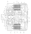
- the drive module according to the present invention has a motor 3 having a stator portion 1 and a rotor portion 2 and a speed reducer 4 integrated with each other, and the motor 3 and the speed reducer 4 are accommodated in a casing 5. .
- the casing 5 includes a first part 5a, a second part 5b, and a third part 5c. That is, the first part 5 a has a short cylinder part 6 and a lid part 7 that closes the opening on the opposite side of the short cylinder part 6.
- the second part 5b is made of a short cylinder
- the third part 5c has a short cylinder part 8 and a thick inner collar part 9 provided on the output side of the short cylinder part 8.
- the stator portion 1 of the motor 3 is fixed to an intermediate portion in the axial direction of the casing 5, and is formed with a stator core 1a formed of a plurality of electromagnetic steel plates laminated in the axial direction, a bobbin 1b made of an insulating material attached to the stator core 1a, And a stator coil (not shown) wound around 1b.
- the rotor unit 2 includes an annular rotor core 2a and a plurality of magnets 2b attached to the outer periphery of the rotor core 2a. That is, the motor 3 is constituted by an electric motor in which the rotor portion 2 is arranged so as to face the inner side in the radial direction of the stator portion 1 with a gap. In this embodiment, a radial gap type is illustrated as an example of the electric motor.
- the drive module is divided into a rotor shaft input portion 10 that rotates as the rotor portion 2 of the motor 3 rotates and a rotor shaft output portion 11 that rotates as the rotor shaft input portion 10 rotates.
- the rotor shaft 12 is provided.
- the rotor shaft input unit 10 includes an intermediate disk part 13 whose axis is disposed on the axis of the casing 5, a cylindrical part 14 provided continuously to the outer peripheral part of the intermediate disk part 13, and the intermediate disk part 13. There is a shaft portion 15 that protrudes from the center portion to the output side.
- the rotor portion 2 of the motor 3 is fitted and fixed to the cylindrical portion 14.
- the rotor shaft output portion 11 is externally fitted to the shaft portion 15 via a bearing (needle roller bearing) 16.
- the shaft portion 15 includes a boss portion 15a on the intermediate disk portion 13 side and a main body shaft 15b projecting from the boss portion 15a, and a needle roller bearing 16 is externally fitted to the main body shaft 15b.
- the rotor shaft output portion 11 includes a cylindrical main body portion 11a and a ring-shaped outer flange portion provided on the intermediate disk portion 13 side of the rotor shaft input portion 10 of the main body portion 11a. 11b.
- the end surface of the outer flange portion 11b on the side of the intermediate disk portion 13 becomes an output portion side corresponding surface 19 where the rotor shaft output portion 11 faces the rotor shaft input portion 10, and faces the output portion side corresponding surface 19.
- the end surface of the intermediate disk portion 13 of the rotor shaft input portion 10 becomes an input portion side corresponding surface 18 where the rotor shaft input portion 10 faces the rotor shaft output portion 11.
- the rotor shaft input portion 10 has a ring-shaped recess 20 formed by an end portion on the output side of the cylindrical portion 14, an intermediate disk portion 13 of the rotor shaft input portion, and a boss portion 15 a of the first output shaft 15.
- the outer flange portion 11 b of the rotor shaft output portion 11 is loosely fitted in the recess 20.
- a pressing structure M described later is provided between the input portion side corresponding surface 18 and the output portion side corresponding surface 19.
- a support shaft portion 21 is provided at the center of the inner surface of the lid portion 7 of the casing 5.
- the support shaft portion 21 includes a base large-diameter portion 21a, an intermediate-diameter portion 21b in the axial intermediate portion, and a small-diameter portion 21c at the end.
- the base large-diameter portion 21a is embedded in the lid portion 7 of the casing 5. It has become.
- a bearing 22 is fitted on the small diameter portion 21 c of the support shaft portion 21.
- the bearing 22 is disposed between an inner ring 23 having a raceway surface 23 a on the outer diameter surface, an outer ring 24 having a raceway surface 24 a on the inner diameter surface, and the inner ring 23 and the outer ring 24 so as to be able to roll.
- This is an angular ball bearing including a rolling element (ball) 25 and a cage (not shown).
- a circumferential cutout 26 is provided on the inner diameter surface of the cylindrical portion 14 on the lid portion 7 side of the intermediate disc portion 13 of the rotor shaft input portion 10, and the outer ring 24 of the bearing 22 is fitted into the circumferential cutout 26. is doing.
- a bearing 28 is externally fitted to the main body 11a of the rotor shaft output part 11.
- the bearing 28 is rotatably disposed between the inner ring 29 having a raceway surface 29 a formed on the outer diameter surface, the outer ring 30 having the raceway surface 30 a formed on the inner diameter surface, and the inner ring 29 and the outer ring 30.
- An angular ball bearing includes a rolling element (ball) 31 and a cage 32 that holds the ball 31.
- a circumferential notch 33 is provided on the inner diameter surface of the inner flange 9 in the third portion 5 c of the casing 5, and the outer ring 30 of the bearing 28 is fitted into the circumferential notch 33.
- the retainer 32 has an integral structure with the first output shaft 35 of the drive module as shown in FIGS. That is, a disc-shaped flange 36 extending in the outer diameter direction is provided at the input side end of the first output shaft 35, and a short cylindrical portion 37 protruding from the outer diameter end of the flange 36 toward the input side. Are continuously provided, and pockets 38 formed of a plurality of notches are formed in the short cylindrical portion 37 at a predetermined pitch along the circumferential direction. For this reason, the short cylindrical portion 37 constitutes a cage 32 having pockets 38 for holding the balls 31 at a predetermined pitch along the circumferential direction.
- the rotor shaft 12 having a structure divided into the rotor shaft input portion 10 and the rotor shaft output portion 11 that rotates as the rotor shaft input portion 10 rotates includes a pair of bearings 22, At 28, it is pivotally supported by the casing 5.
- the axis of the rotor shaft 12, that is, the axis of the rotor shaft input unit 10 and the rotor shaft output unit 11, the axis of the support shaft 21, and the axis of the output shaft 35 are on the same axis.
- the axis forms the axis of the drive module.
- the input side end face 23b of the inner ring 23 of the bearing 22 abuts on a step part 21d between the small diameter part 21c and the medium diameter part 21b of the support shaft part 21, and the output side end face 24c of the outer ring 24 of the bearing 22 is
- the rotor shaft input portion 10 is in contact with the end face 26 a of the circumferential cutout portion 26.
- the input side end face 29 b of the inner ring 29 of the bearing 28 abuts on the output side end face 40 of the outer flange part 11 b of the rotor shaft output part 11, and the output side end face 30 c of the outer ring 30 of the bearing 28 is the third end of the casing 5. It abuts against the end face 33a of the circumferential notch 33 of the inner flange portion 9 of the portion 5c.
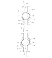
- the pressing structure portion M is provided with a plurality of torque cam grooves 41, 42 provided at a predetermined pitch along the circumferential direction so as to face the input portion side corresponding surface 18 and the output portion side corresponding surface 19. And rolling elements (balls) 43 disposed between the corresponding torque cam grooves 41, 42.
- the torque cam grooves 41 and 42 are provided with inclined surfaces 41a and 42a. That is, the shape of the cross section perpendicular to the axial direction of the torque cam grooves 41 and 42 is a flat semi-elliptical shape in which the radius of curvature on the opening side is larger than the radius of curvature of the bottom.
- a ball as one rolling element 43 is arranged at 41, 42.
- the rolling elements ride on the inclined surfaces 41a and 42a. That is, the ball 43 moves up the inclined surfaces 41a and 42a by a change in the relative rotational phase between the rotor shaft input unit 10 and the rotor shaft output unit 11. Accordingly, a pressing force is generated in a direction (axial direction) in which the distance between the rotor shaft input unit 10 and the rotor shaft output unit 11 is increased, and the rotor shaft configured by the rotor shaft input unit 10 and the rotor shaft output unit 11 A load is applied to bearings 22 and 28 that support 12 at both axial ends. This load becomes larger as the power of the rotor unit 2 is larger.
- the upper diagram of FIG. 5 shows the position of the rolling element 43 when no torque is input.
- the arrangement with a slight preload is suitable for suppressing the generation of abnormal noise.
- the lower figure of FIG. 5 has shown the position of the rolling element 43 when a torque acts.
- the rolling element (ball) 43 of the pressing structure M moves in the rotation direction, the rolling element 43 climbs the inclined surfaces 41a and 42a, and the distance between the rotor shaft input unit 10 and the rotor shaft output unit 11 increases in the direction X.
- X is a value that increases as the torque increases.
- the speed reducer 4 can be configured by the first transmission mechanism T1 of the microtraction mechanism including the bearing 28.
- a pressing force to the output side acts on the bearing 28 in the pressing structure portion M, and the end surface 29b of the inner ring 29 of the bearing 28 is pressed to the output side in the outer flange portion 11b of the rotor shaft output portion 11, This pressing force is transmitted to the outer ring 30 via the ball 31. Therefore, a pressure contact force is applied to the raceway surface 29 a of the inner ring 29 and the raceway surface 30 a of the outer ring 30.
- the bearing 28 is filled with traction grease. For this reason, traction is generated in the bearing 28 and is decelerated and output as a microtraction drive.
- the traction grease has increased viscosity resistance so as to increase the torque at the time of rotation, and lithium soap grease using lithium soap as a thickener is common.
- the drive module has a configuration in which the hollow motor 3 and the microtraction speed reducer 4 are combined.
- the output-side bearing 28 constitutes a microtraction speed reducer.
- a member (rotor shaft input portion 10) that rotates integrally with the rotor portion 2 of the motor 3 and the rotor shaft output portion 11 on the input side of the microtraction speed reducer.
- the torque cam grooves 41 and 42 having the inclined surfaces 41a and 42a are arranged. Therefore, it is possible to provide a compact flat motor-integrated hybrid speed reducer with small initial motion torque and high durability.
- the traction mechanism of the first transmission mechanism T1 can be configured by the bearing 28, and the compactness can be adopted. Moreover, since the cage 32 is integrated with the first output shaft 35, the first transmission mechanism T1 is changed to the first transmission mechanism T1. 1 Rotational force transmission to the output shaft 35 is stabilized.
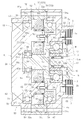
- the drive module shown in FIG. 1 is further provided with another second transmission mechanism T2.
- the outer casing 50 is provided in the third part 5 c of the casing 5, and the end casing 52 on the output side is provided in the outer casing 50 via the intermediate short cylindrical body 51, whereby the sub casing 53 is provided.
- the second transmission mechanism T2 is accommodated in the sub casing 53.
- the outer flange 50, the intermediate short cylinder 51, and the end cylinder 52 are provided with through holes 50a, 51a, 52a, respectively, and bolt members (not shown) are provided in the through holes 50a, 51a, 52a. Is inserted, and the third portion 5c, the short cylindrical body 51, and the end cylindrical body 52 are integrated.
- the second transmission mechanism T2 includes a sun member 55 provided on the first output shaft 35, a planet member 56 that engages with the sun member 55, an annular member 57 that engages with the planet member 56, and the planet member. 56 and a carrier 59 that transmits the rotational driving force to the second output shaft 58 by engaging with and rotating. For this reason, the rotational force from the first output shaft 35 is decelerated by the second transmission mechanism T ⁇ b> 2 and transmitted to the second output shaft 35.
- the second transmission mechanism T2 shown in FIG. 6 includes a planetary traction drive in which the sun member 55 is a sun roller 55A, the planetary member 56 is a planetary roller 56A, and the annular member 57 is a ring roller 57A.
- the first output shaft 35 (35A) in this case has a large-diameter main body portion 35a and an end small-diameter portion 35b, and an annular sun roller 55A is fitted and fixed to the main body portion 35a.
- the second output shaft 58 is formed of a disk-shaped body 61 having a concave portion 61a into which the small-diameter portion 35b is fitted on the inner surface, and a plurality of protrusions projecting to the inner surface on the outer diameter side of the disk-shaped body 61.
- a carrier 59 having a shaft 60 is provided.
- a planetary roller 56 ⁇ / b> A is externally fitted to each protruding shaft 60 via a bearing 62.
- the second output shaft 58 is rotatably supported by the sub casing 53 by a pair of bearings 64 and 65.
- the bearing 64 is rotatably disposed between an inner ring 66 having a raceway surface 66 a formed on the outer diameter surface, an outer ring 67 having a raceway surface 67 a formed on the inner diameter surface, and the inner ring 66 and the outer ring 67.
- a rolling element (ball) 68 and a retainer (not shown) that holds the ball 68 are provided.
- the bearing 65 is disposed between the inner ring 69 having the raceway surface 69 a on the outer diameter surface, the outer ring 70 having the raceway surface 70 a on the inner diameter surface, and the inner ring 69 and the outer ring 70 so as to be able to roll.
- Rolling elements (balls) 71 and a retainer (not shown) that holds the balls 71 are provided.
- a ring-shaped recess 73 is provided on the output side end surface of the third portion 5 c of the casing 5, and a bearing 64 is fitted in the recess 73.
- the bearing support member 74 is attached to the end surface 75 of the protruding shaft 60 of the carrier 59.
- the bearing support member 74 includes a thin ring body 74a and a thick short cylindrical body 74b protruding from the ring body 74a. With the ring body 74a in contact with the end surface 75 of the projecting shaft 60, the screw member 76 is screwed into the screw hole provided in the end surface 75 of the projecting shaft 60 through the through hole provided in the ring body 74a. By wearing, the bearing support member 74 can be attached to the protruding shaft 60.
- the outer cylindrical surface of the short cylindrical body 74 b is provided with a notch 77, and the inner ring 66 of the bearing 64 is fitted therein, and the outer ring 67 of the bearing 64 is fitted into the notch 78 on the outer peripheral side inner surface of the recess 73.
- a notch 80 is provided on the input side of the outer peripheral surface of the second output shaft 58, the inner ring 69 of the bearing 65 is fitted, and a notch 81 is provided on the input side of the inner peripheral surface of the end cylinder 52.
- the outer ring 70 of the bearing 65 is fitted in the notch 81.
- a notch portion 82 is provided on the output side of the outer peripheral surface of the output shaft 58, and the seal member (sealing device) 83 is fitted into the notch portion 82. The gap between the outer peripheral surface of the output side and the output side end cylindrical body 52 is sealed.
- a bearing 85 is mounted on the small diameter portion 35b of the first output shaft 35 (35A) inserted into the concave portion 61a of the second output shaft 58.
- the bearing 85 is rotatably disposed between an inner ring 86 having a raceway surface 86 a formed on the outer diameter surface, an outer ring 87 having a raceway surface 87 a formed on the inner diameter surface, and the inner ring 86 and the outer ring 87.
- a rolling element (ball) 88 and a retainer (not shown) that holds the ball 88 are provided.
- the inner ring 86 of the bearing 85 is fitted on the small diameter portion 35b of the first output shaft 35 (35A), and the outer ring 87 of the bearing 85 is fitted on a notch 89 provided on the peripheral wall of the recess 61a of the second output shaft 58.
- the ring roller 57A which is the annular member 57, is provided with a flat convex ridge 90 on its inner surface, and the outer diameter surface 56a of the planetary roller 56A, which is the planetary member 56, is in pressure contact with the flat convex ridge 90.
- the other configuration of the drive module shown in FIG. 6 is the same as the configuration of the drive module shown in FIG. 1, and therefore, the configuration will be described with reference to FIG. Omitted.
- the first output shaft 35 rotates when the motor 3 is driven, as in the drive module shown in FIG. For this reason, the first output shaft 35 becomes an input shaft of the second transmission mechanism T2 configured by the planetary traction drive. Further, when the first output shaft 35 that is the input shaft of the second transmission mechanism T2 rotates, the sun roller 55A that is the sun member 55 rotates along with the rotation of the input shaft. Due to the rotation of the sun roller 55A, the planetary roller 56A as the planetary member 56 revolves while rotating. As a result, the second output shaft is decelerated and rotated.
- the second transmission mechanism T2 decelerates the driving force of the input shaft constituted by the first output shaft 35 with a predetermined reduction ratio and transmits it to the second output shaft 58. Therefore, it is possible to reliably obtain a desired reduction ratio by having two transmissions.
- the second transmission mechanism T2 is configured by a planetary traction drive in which the sun member 55 is a sun roller 55A, the planetary member 56 is a planetary roller 56A, and the annular member 57 is a ring roller 57A.
- the sun member 55 is a sun gear 55B
- the planetary member 56 is a planetary gear 56B supported by a carrier 59 (59B)
- the annular member 57 is a ring gear 57B.
- the planetary gear mechanism is efficient, and the planetary traction drive enables low noise and low vibration output.
- the pressing structure portion M corresponds to the input portion side corresponding surface 18 and the output portion side.
- Torque cam grooves 41 and 42 provided so as to face the surface 19 and rolling elements 43 provided between the corresponding torque cam grooves 41 and 42 are provided.
- the pair of opposing torque cam grooves 41 and 42 are arranged at a predetermined pitch along the circumferential direction, but the number thereof can be arbitrarily set.
- the angular ball bearing is used as the bearing 28 used in the first transmission mechanism T1, but similarly, a tapered roller bearing that can load a radial load and an axial load in one direction may be used. Good.
- the second transmission mechanism T2 the number of planetary members 56 can be arbitrarily set.
- a motor and a speed reducer can be used for a drive mechanism such as an electric vehicle.
- a transmission mechanism including a traction drive mechanism is provided.
Landscapes
- Engineering & Computer Science (AREA)
- General Engineering & Computer Science (AREA)
- Mechanical Engineering (AREA)
- Power Engineering (AREA)
- Friction Gearing (AREA)
- Connection Of Motors, Electrical Generators, Mechanical Devices, And The Like (AREA)
Abstract
ロータ軸入力部(10)とロータ軸出力部(11)とに分割された構造のロータ軸(12)と、ロータ軸出力部(11)の回転駆動力を所定の減速比で減速して出力軸(35)に伝達する第1伝達機構(T1)と、ロータ軸入力部(10)とロータ軸出力部(11)との間に介在されて、ロータ軸入力部(10)とロータ軸出力部(11)との相対的押圧力を調整する押圧構造部(M)とを備える。
Description
本発明は、駆動モジュールに関し、特にステータ部とロータ部とを有するモータと、減速機とを一体構造とした駆動モジュールに関する。
電動車両などの駆動機構では、モータの小型化、低価格化などの目的のため、モータと、減速機とを組み合わせたもの(すなわち、駆動モジュール)を使用することがある。このような駆動モジュールの減速機(減速機構)には、トラクションドライブ機構を用いる場合がある。トラクションドライブ機構は、低騒音、低振動の特徴をいかしてこのような駆動モジュールに用いられる。
トラクションドライブ減速機(マイクロトラクション機構)は、軸受の潤滑にトラクショングリースを用いて、軸受に予圧を与えることで、トラクションドライブの機能を付与することになる。
従来には、転動体として鋼球を用い、外輪と鋼球の玉と内輪とが入力軸反先端方向のスラストに抗するように構成されたマイクロトラクションが提案されている(特許文献1)。特許文献1の図1に示すものは、その外輪が、内輪軌道面上に配置された複数の玉を、外輪軌道面で圧接するように焼嵌めされて、玉と接触点において、接触面の法線方向の圧接力である法線力が強く加えられる状態となるものである。
また、特許文献1の図2には、中心軸線を囲むハウジングの中央を弾性外輪で構成したものが記載されている。すなわち、弾性外輪は、その断面形状がチャンネル状とされ、ボルト・ナットの締付によって、弾性外輪の外輪軌道面は内周方向に弾性変形し、内輪軌道面上に配設された複数の玉を、外輪軌道面に圧接するものである。
特許文献1の図3に示すものは、第1テーパ面を有する第1テーパリングと、第2テーパ面を有する第2テーパリングと、第1テーパリングと第2テーパリングを締結する締結構造を備え、第1テーパリングと第2テーパリングの間隔を締結構造にて調整する構成となっている。また、この第1テーパリングと第2テーパリングとが外輪を構成し、かつ、各テーパリングにテーパ面が形成され、この一対のテーパ面にてV溝からなる外輪軌道面が構成される。このため、締結構造による調整にて、内輪軌道面上に配設された複数の玉を、外輪軌道面に圧接するものである。
特許文献1の図4に示すものは、ハウジング内の出力側端部と外輪との間にその間を拡大する方向に付勢する第1バネが配設され、一対の内輪間にその間を拡大する方向に付勢する第2バネが配設される構成となっている。このため、第1バネは、外輪を入力軸反先端方向に押し、玉を介し内輪を押圧する。 第2バネは、入力軸支持軸受の内輪を入力軸反先端方向に押し、玉を介し外輪を押圧する。
特許文献1の図5では、一対の円すいころ軸受を備え、出力側の円すいころ軸受の外輪が入力側へ付勢するバネを備えたものである。出力側の円すいころにおいて、ころと外輪軌道面および内輪軌道面との接触面にこのバネによる法線力が働き、そのため、複数のころが、内輪軌道面および外輪駆動面と滑りを起こさず転動するように構成されている。
特許文献2では、入力軸の中心軸廻りに公転する回転体と、入力軸又は出力軸の軸線廻りに配設される押圧円環とを備え、この押圧円環には、回転体側に複数の傾斜面が設けられている。そして、押圧円環の傾斜面が、押圧円環を回転させたときに、入力軸に設けられた内輪と、筐体に対して回転方向が固定された外輪との回転方向への相対的押圧力を調整する傾斜面としている。すなわち、内輪と外輪の回転体方向への相対的押圧力を調整自在とする傾斜面によって、マイクロトラクションに予圧を付与するものである。
特許文献1の図1に示すものでは、内輪軌道面上に配置された複数の玉を、外輪軌道面で圧接するように外輪を焼嵌めさせる必要があり、その圧接力の調整が難しい。また、特許文献1の図2及び図3に示すものでは、ボルト部材を有する締結構造を必要として、部品点数の増加および締結構造の締結力に調整作業が面倒である。
また、特許文献1の図4及び図5に示すように、付勢機構としてバネを用いるものでは、以下のような問題が生じる。バネによる押圧力は、マイクロトラクションドライブが満足すべき最大の伝達トルクにおいても、外輪と回転体と内輪との間にスリップが生じない強さに設定される。このバネによる押圧力は、一度設定されると常に一定である。しかし、通常よく使用する伝達トルクに対して、この押圧力は過大であり、押圧力が大きい場合、外輪と回転体との接触面、内輪と回転体との接触面が鱗状にはがれるフレーキング等の破損を起こす可能性が高くなる。
これらを解決する手段として特許文献2では、傾斜面を使って負荷トルクによって予圧を変更する構造としているが、本機構により軸方向のサイズが大きい構造となり、コンパクトな減速機にはならない。
そこで、本発明は、上記課題に鑑みて、初動トルクの小さく、耐久性の高いコンパクトな扁平型のモータ一体型減速機である駆動モジュールを提供するものである。
本発明の駆動モジュールは、ステータ部およびロータ部を有するモータと、減速機とを一体構造とした駆動モジュールであって、第1出力軸と、前記ロータ部の回転に伴って回転するロータ軸入力部と、前記ロータ軸入力部の回転に伴って回転するロータ軸出力部とを備えるロータ軸と、前記ロータ軸出力部の回転駆動力を所定の減速比で減速して前記第1出力軸に伝達するトラクションドライブ機構にて構成される第1伝達機構と、前記ロータ軸入力部と前記ロータ軸出力部との間に設けられ、前記ロータ軸入力部と前記ロータ軸出力部との相対的押圧力を調整する押圧構造部とを備えたものである。
ロータ軸入力部が回転することによって、ロータ軸入力部とロータ軸出力部の間で相対的な回転位相が変化する。また、ロータ軸入力部とロータ軸出力部との間には、ロータ軸入力部とロータ軸出力部との相対的押圧力を調整する押圧構造部が介在されているので、第1伝達機構を構成するトラクションドライブ機構にトラクション力が発生し、ロータ軸入力部からの回転がマイクロトラクションドライブとして減速して第1出力軸に出力される。
ロータ軸入力部がロータ軸出力部に対面する入力部側対応面を有するとともに、ロータ軸出力部がロータ軸入力部に対面する出力部側対応面を有し、前記押圧構造部は、入力部側対応面及び出力部側対応面に相対面するように設けられるトルクカム溝と、対応するトルクカム溝間に配設される転動体とを備え、ロータ軸入力部に回転トルクを付与した際に、転動体が乗り上げて、ロータ軸入力部とロータ軸出力部との相対的押圧力を調整する傾斜面を各トルクカム溝に設けるが好ましい。
このようにトルクカム溝を設けた場合、ロータ軸入力部とロータ軸出力部との間の相対的な回転位相の変化によって、この相対的な回転位相の変化によって転動体が傾斜面を登るように移動し、ロータ軸入力軸とロータ軸出力軸の距離が離れる方向に押圧力が発生し、このロータ軸を両端で支えている軸受に荷重が負荷される。この荷重はロータ部の動力が大きいほど大きな荷重となる。押圧手段の転動体が回転方向に移動することで、転動体が傾斜面を登り、ロータ軸入力部とロータ軸出力部の距離が離れる方向に移動する。この移動量はトルクが増加するほど大きくなる。
第1伝達機構は、ロータ軸出力部に固定される内輪と、ケーシングに固定される外輪と、内輪の転動面と外輪の転動面との間に配設される転動体と、内輪と外輪との間に介在されて転動体を保持する保持器とを備え、この保持器が前記第1出力軸と一体構造をなすように設定するのが好ましい。
このように構成されることによって、第1伝達構造のトラクション機構を軸受にて構成でき、コンパクト化を採用でき、しかも、保持器は第1出力軸と一体構造であるので、この第1伝達機構から第1出力軸への回転力伝達が安定する。
前記保持器と一体構造をなす第1出力軸を入力軸として、この入力軸の回転駆動力を所定の減速比で減速して第2出力軸に伝達する第2伝達機構を備え、この第2伝達機構が、前記第1出力軸に設けられる太陽部材と、この太陽部材に係合する遊星部材と、この遊星部材に係合する環状部材と、前記遊星部材に係合して回転することにより回転駆動力を第2出力軸に伝達するキャリアとを備えている遊星構造であるように構成できる。
このように構成することによって、第2伝達機構にて、第1出力軸にて構成される入力軸の転駆動力を所定の減速比で減速して第2出力軸に伝達することができ、2機の変速機を有することになって、所望の減速比を確実に得ることができる。
第2伝達機構は、前記太陽部材をサンギアとし、前記遊星部材をプラネタリアギアとし、前記環状部材をリングギアとした遊星歯車機構にて構成されるものであっても、太陽部材をサンローラとし、前記遊星部材をプラネタリアローラとし、前記環状部材をリングローラとした遊星トラクションドライブにて構成されるものであってもよい。すなわち、第2伝達機構を、遊星歯車機構にて構成したり、遊星トラクションドライブにて構成したりできる。遊星歯車機構であれば、効率が良く、遊星トラクションドライブであれば、低騒音で低振動な出力が可能である。
本発明の駆動モジュールでは、初動トルクの小さく、耐久性の高いコンパクトな扁平型のモータ一体型減速機を構成できる。
以下本発明の実施の形態を図1~図7に基づいて説明する。本発明に係る駆動モジュールは、ステータ部1とロータ部2とを有するモータ3と、減速機4とを一体構造としたものであり、モータ3と減速機4等はケーシング5に収容されている。
ケーシング5は、第1部5aと第2部5bと第3部5cとを備える。すなわち、第1部5aは短筒部6とこの短筒部6の反出力側の開口部を塞ぐ蓋部7を有する。また、第2部5bは短筒体からなり、第3部5cは、短筒部8とこの短筒部8の出力側に設けられる肉厚の内鍔部9とを有する。
モータ3のステータ部1はケーシング5の軸方向中間部位に固定され、軸方向に積層した複数の電磁鋼板で形成されたステータコア1aと、ステータコア1aに装着された絶縁材料からなるボビン1bと、ボビン1bに巻回された図示省略のステータコイルとを有する。ロータ部2は、環状のロータコア2aと、ロータコア2aの外周に取り付けられた複数のマグネット2bとを有する。すなわち、このモータ3は、ロータ部2が、ステータ部1の半径方向内側に隙間をもって対向するように配置された電動モータで構成される。本実施形態では、電動モータの一例として、ラジアルギャップ型を例示している。
そして、この駆動モジュールは、モータ3のロータ部2の回転に伴って回転するロータ軸入力部10と、ロータ軸入力部10の回転に伴って回転するロータ軸出力部11とに分割された構造のロータ軸12を備える。
ロータ軸入力部10は、その軸心がケーシング5の軸心上に配設される中間円盤部13と、この中間円盤部13の外周部に連設される円筒部14と、中間円盤部13の中心部から出力側へ突出する軸部15を有する。そして、円筒部14にモータ3のロータ部2が外嵌固定されている。
また、軸部15には、軸受(針状ころがり軸受)16を介してロータ軸出力部11が外嵌されている。なお、軸部15は、中間円盤部13側のボス部15aと、このボス部15aから突設される本体軸15bとからなり、本体軸15bに針状ころがり軸受16が外嵌されている。
ロータ軸出力部11は、図1~図3に示すように、円筒状の本体部11aと、この本体部11aのロータ軸入力部10の中間円盤部13側に設けられるリング状の外鍔部11bとからなる。このため、外鍔部11bの中間円盤部13側の端面が、ロータ軸出力部11がロータ軸入力部10に対面する出力部側対応面19となり、この出力部側対応面19に相対面するロータ軸入力部10の中間円盤部13の端面が、ロータ軸入力部10がロータ軸出力部11に対面する入力部側対応面18となる。また、ロータ軸入力部10には、円筒部14の出力側の端部と、ロータ軸入力部の中間円盤部13と、第1出力軸15のボス部15aとで、リング状の凹部20が形成され、この凹部20に、ロータ軸出力部11の外鍔部11bが遊嵌されている。そして、入力部側対応面18と出力部側対応面19との間に、後述する押圧構造部Mが設けられている。
ところで、図1に示すように、ケーシング5の蓋部7の内面中央部には支持軸部21が設けられている。支持軸部21は、基部大径部21aと、軸方向中間部の中径部21bと、端部の小径部21cとからなり、基部大径部21aが、ケーシング5の蓋部7に埋設一体化されている。そして、この支持軸部21の小径部21cには軸受22が外嵌される。
この軸受22は、外径面に軌道面23aが形成された内輪23と、内径面に軌道面24aが形成された外輪24と、内輪23と外輪24との間に転動自在に配設される転動体(ボール)25と、図示省略の保持器とを備えたアンギュラ玉軸受である。そして、ロータ軸入力部10の中間円盤部13よりも蓋部7側の円筒部14の内径面に周方向切欠部26が設けられ、この周方向切欠部26に軸受22の外輪24が嵌合している。
また、ロータ軸出力部11の本体部11aには軸受28が外嵌されている。軸受28は、外径面に軌道面29aが形成された内輪29と、内径面に軌道面30aが形成された外輪30と、内輪29と外輪30との間に転動自在に配設される転動体(ボール)31と、ボール31を保持する保持器32を備えたアンギュラ玉軸受である。そして、ケーシング5の第3部5cにおける内鍔部9の内径面に周方向切欠部33が設けられ、この周方向切欠部33に軸受28の外輪30が嵌合されている。
この保持器32は、図2~図4に示すように、この駆動モジュールの第1出力軸35と一体構造となっている。すなわち、第1出力軸35の入力側の端部に、外径方向に延びる円盤形状の鍔部36が設けられ、この鍔部36の外径端部から入力側へ突出される短円筒部37が連設され、この短円筒部37に周方向に沿って所定ピッチで複数の切欠部からなるポケット38が形成されている。このため、短円筒部37が、周方向に沿って所定ピッチでボール31を保持するポケット38を有する保持器32を構成する。
従って、図1に示すように、ロータ軸入力部10と、ロータ軸入力部10の回転に伴って回転するロータ軸出力部11とに分割された構造のロータ軸12は、一対の軸受22、28にて、ケーシング5に回転自在に枢支される。この場合、ロータ軸12の軸心、すなわち、ロータ軸入力部10及びロータ軸出力部11の軸心と、支持軸部21の軸心と、出力軸35の軸心は、同一軸心上に配設され、この軸心がこの駆動モジュールの軸心をなす。
ところで、軸受22の内輪23の入力側端面23bは、支持軸部21の小径部21cと中径部21bとの間の段差部21dに当接し、軸受22の外輪24の出力側端面24cは、ロータ軸入力部10の周方向切欠部26の端面26aに当接している。また、軸受28の内輪29の入力側端面29bは、ロータ軸出力部11の外鍔部11bの出力側端面40に当接し、軸受28の外輪30の出力側端面30cは、ケーシング5の第3部5cの内鍔部9の周方向切欠部33の端面33aに当接している。
図4に示すように、押圧構造部Mは、入力部側対応面18及び出力部側対応面19に相対面するように、周方向に沿って所定ピッチで複数個設けられるトルクカム溝41,42と、対応するトルクカム溝41,42間に配設される転動体(ボール)43とを備える。また、各トルクカム溝41,42には傾斜面41a,42aが設けられている。すなわち、トルクカム溝41,42の軸方向に垂直な断面の形状は、開口側の曲率半径を底部の曲率半径よりも大きくした扁平半楕円形状としている。
次に前記のような駆動モジュールの動作を説明する。モータ3に電流が供給されることによって、ロータ部2が回転すれば、このロータ部2が外嵌されているロータ軸入力部10がその軸心廻りに回転する。この場合、ロータ軸入力部10とロータ軸出力部11との間に押圧構造部Mが配設されているので、ロータ軸入力部10とロータ軸出力部11との間で相対的に回転位相が変化する。すなわち、ロータ軸入力部10の端面18及びロータ軸出力部11の端面19に、それぞれ複数の同数のテーパ状のトルクカム溝(傾斜面をするカム溝)が形成され、しかも、対になるトルクカム溝41,42に一つの転動体43としてのボールが配置されている。このため、ロータ軸入力部10に回転トルクを付与した際に、転動体(ボール43)が傾斜面41a、42a乗り上げる。すなわち、ロータ軸入力部10とロータ軸出力部11との間で相対的な回転位相の変化によって、ボール43が傾斜面41a、42aを登ように移動する。これによって、ロータ軸入力部10とロータ軸出力部11との距離が離れる方向(軸方向)に押圧力が発生し、このロータ軸入力部10とロータ軸出力部11とで構成されるロータ軸12をその軸方向両端部で支えている軸受22,28に荷重が負荷される。この荷重はロータ部2の動力が大きいほど大きな荷重となる。
すなわち、図5の上図はトルクが入力されていない場合の転動体43の位置を示している。若干の予圧をかけた状態で配置された方が異音の発生などを抑制するのに適している。また、図5の下図はトルクが作用した場合の転動体43の位置を示している。押圧構造部Mの転動体(ボール)43が回転方向に移動することで、転動体43が傾斜面41a、42aを登り、ロータ軸入力部10とロータ軸出力部11の距離が離れる方向にXだけ移動する。Xはトルクが増加するほど大きくなる値である。
このように、減速機4は、軸受28で構成されるマイクロトラクション機構の第1伝達機構T1で構成できる。この場合、押圧構造部Mにて軸受28に出力側への押圧力が作用し、ロータ軸出力部11の外鍔部11bにて、軸受28の内輪29の端面29bが出力側へ押圧され、この押圧力がボール31を介して外輪30に伝達される。このため、内輪29の軌道面29aと外輪30の軌道面30aとに圧接力を受ける。また、この軸受28にトラクショングリースが充填される。このため、軸受28にトラクションが発生し、マイクロトラクションドライブとして減速して出力される。ここで、トラクショングリースは、回転時のトルクを大きくするように粘性抵抗を高めたものであり、増ちょう剤にリチウム石けんを使用したリチウム石けん系グリースが一般的である。
このように、この駆動モジュールは、中空型のモータ3とマイクロトラクション減速機4を組み合わせた構成となっている。そして、モータ3の出力軸(ロータ軸12)を支える軸方向両端の軸受22,28のうち、出力側の軸受28にてマイクロトラクション減速機が構成される。また、モータ3の中空部のスペースに、モータ3のロータ部2と一体に回転する部材(ロータ軸入力部10)と前記マイクロトラクション減速機の入力側となるロータ軸出力部11との間に傾斜面41a,42aを持ったトルクカム溝41,42を配置することになる。このため、初動トルクの小さく、耐久性の高いコンパクトな扁平型のモータ一体型ハイブリッド減速機を提供できる。また、第1伝達機構T1のトラクション機構を軸受28にて構成でき、コンパクト化を採用でき、しかも、保持器32は第1出力軸35と一体構造であるので、この第1伝達機構T1から第1出力軸35への回転力伝達が安定する。
次に、図6に示す駆動モジュールでは、図1に示す駆動モジュールにさらに別の第2伝達機構T2を備える。この場合、ケーシング5の第3部5cに外鍔部50を設け、この外鍔部50に、中間短円筒体51を介して出力側の端部筒体52を設けることによって、副ケーシング53を形成している。そして、この副ケーシング53内に第2伝達機構T2が収納されている。なお、外鍔部50、中間短円筒体51、及び端部筒体52には、それぞれ、貫通孔50a、51a、52aが設けられ、この貫通孔50a、51a、52aにボルト部材(図示省略)が挿通されて、第3部5cと短円筒体51と端部筒体52とが一体化される。
第2伝達機構T2は、前記第1出力軸35に設けられる太陽部材55と、この太陽部材55に係合する遊星部材56と、この遊星部材56に係合する環状部材57と、前記遊星部材56に係合して回転することにより回転駆動力を第2出力軸58に伝達するキャリア59とを備えている。このため、第1出力軸35からの回転力が第2伝達機構T2で減速されて第2出力軸35に伝達される。
この図6の第2伝達機構T2では、太陽部材55をサンローラ55Aとし、前記遊星部材56をプラネタリアローラ56Aとし、前記環状部材57をリングローラ57Aとした遊星トラクションドライブにて構成している。
すなわち、この場合の第1出力軸35(35A)は、大径の本体部35aと、端部の小径部35bとを有し、本体部35aに円環形状のサンローラ55Aが外嵌固定されている。また、第2出力軸58は、小径部35bが嵌入される凹部61aを内面に有する円盤形状体61にて形成され、この円盤形状体61の外径側の内面に突出される複数本の突出軸60を有するキャリア59が設けられている。また、各突出軸60には、軸受62を介してプラネタリアローラ56Aが外嵌されている。
第2出力軸58は、一対の軸受64,65にて回転自在に副ケーシング53に支持されている。軸受64は、外径面に軌道面66aが形成された内輪66と、内径面に軌道面67aが形成された外輪67と、内輪66と外輪67との間に転動自在に配設される転動体(ボール)68と、ボール68を保持する図示省略の保持器を備える。また、軸受65は、外径面に軌道面69aが形成された内輪69と、内径面に軌道面70aが形成された外輪70と、内輪69と外輪70との間に転動自在に配設される転動体(ボール)71と、ボール71を保持する図示省略の保持器を備える。
すなわち、ケーシング5の第3部5cの出力側端面に、リング形状の凹部73が設けられ、この凹部73内に軸受64が嵌合状となっている。この場合、軸受用支持部材74がキャリア59の突出軸60の端面75に付設される。軸受用支持部材74は、薄肉のリング体74aと、このリング体74aから突設される厚肉の短円筒体74bとからなる。リング体74aを突出軸60の端面75に当接させた状態で、このリング体74aに設けられた貫孔を介して、突出軸60の端面75に設けられたねじ孔にねじ部材76を螺着することによって、突出軸60に軸受用支持部材74を取付けることができる。
短円筒体74bの外径面には切欠部77が設けられ、軸受64の内輪66が嵌合するとともに、凹部73の外径側内周面に切欠部78に、軸受64の外輪67が嵌合している。また、第2出力軸58の外周面の入力側に切欠部80が設けられ、軸受65の内輪69が嵌合するとともに、端部筒体52の内周面の入力側に切欠部81が設けられ、この切欠部81に軸受65の外輪70が嵌合している。また、出力軸58の外周面の出力側に切欠部82が設けられ、この切欠部82にシール部材(密封装置)83に嵌合され、このシール部材(密封装置)83にて、出力軸58の外周面と出力側の端部筒体52との間の隙間を密封している。
また、第2出力軸58の凹部61aに嵌入される第1出力軸35(35A)の小径部35bに軸受85が装着されている。軸受85は、外径面に軌道面86aが形成された内輪86と、内径面に軌道面87aが形成された外輪87と、内輪86と外輪87との間に転動自在に配設される転動体(ボール)88と、ボール88を保持する図示省略の保持器を備える。そして、軸受85の内輪86が第1出力軸35(35A)の小径部35bに外嵌され、軸受85の外輪87が第2出力軸58の凹部61aの周壁に設けられた切欠部89に嵌合されている。
環状部材57であるリングローラ57Aは、その内径面に扁平凸隆起90が設けられ、この扁平凸隆起90に、遊星部材56であるプラネタリアローラ56Aの外径面56aが圧接している。なお、図6に示す駆動モジュールの他の構成は、図1に示す駆動モジュールの構成と同様であるので、それらの構成については、図6において、図1と同一の符号を附して説明を省略する。
このように、構成された駆動モジュールでは、図1に示す駆動モジュールと同様、モータ3が駆動すれば、第1出力軸35が回転することになる。このため、この第1出力軸35が、遊星トラクションドライブにて構成している第2伝達機構T2の入力軸となる。また、第2伝達機構T2の入力軸である第1出力軸35が回転すれば、この入力軸の回転に伴って太陽部材55であるサンローラ55Aが回転する。このサンローラ55Aの回転によって、遊星部材56であるプラネタリアローラ56Aが自転しながら公転する。これによって、第2出力軸が減速されて回転することになる。
このように構成することによって、第2伝達機構T2にて、第1出力軸35にて構成される入力軸の転駆動力を所定の減速比で減速して第2出力軸58に伝達することができ、2機の変速機を有することになって、所望の減速比を確実に得ることができる。
ところで、図6では、第2伝達機構T2では、太陽部材55をサンローラ55Aとし、前記遊星部材56をプラネタリアローラ56Aとし、前記環状部材57をリングローラ57Aとした遊星トラクションドライブにて構成しているが、図7に示すような遊星歯車機構にて構成してもよい。
すなわち、太陽部材55をサンギア55Bとし、遊星部材56をキャリア59(59B)に支持されるプラネタリアギア56Bとし、環状部材57をリングギア57Bとした遊星歯車機構にて構成される。遊星歯車機構であれば、効率がよく、遊星トラクションドライブであれば、低騒音で低振動な出力が可能となる。
以上、本発明の実施形態につき説明したが、本発明は前記実施形態に限定されることなく種々の変形が可能であって、押圧構造部Mとして、入力部側対応面18及び出力部側対応面19に相対面するように設けられるトルクカム溝41,42と、対応するトルクカム溝41,42間に配設される転動体43とを備えたものである。このため、相対向する一対のトルクカム溝41,42は、周方向に沿って所定ピッチでは配設されるが、その数は任意に設定できる。また、第1伝達機構T1に用いる軸受28として、前記実施形態では、アンギュラ玉軸受を用いたが、同様に、ラジアル荷重と一方向のアキシアル荷重を負荷することができる円すいころ軸受を用いてもよい。第2伝達機構T2としても、遊星部材56の数も任意に設定できる。
モータと減速機とを組み合わせたものであって、電動車両などの駆動機構に用いることができる。トラクションドライブ機構にて構成される伝達機構を備える。
1 ステータ部
2 ロータ部
3 モータ
4 減速機
10 ロータ軸入力部
11 ロータ軸出力部
12 ロータ軸
18 端面(出力部側対応面)
19 端面(入力部側対応面)
29 内輪
30 外輪
31 転動体(ボール)
32 保持器
35 出力軸(第1出力軸)
41,42 トルクカム溝
41a,42a 傾斜面
43 転動体
55 太陽部材
55A サンローラ
55B サンギア
56 遊星部材
56A プラネタリアローラ
56B プラネタリアギア
57 環状部材
57A リングローラ
57B リングギア
58 第2出力軸
59、59B キャリア
M 押圧構造部
T1 第1伝達機構
T2 第2伝達機構
2 ロータ部
3 モータ
4 減速機
10 ロータ軸入力部
11 ロータ軸出力部
12 ロータ軸
18 端面(出力部側対応面)
19 端面(入力部側対応面)
29 内輪
30 外輪
31 転動体(ボール)
32 保持器
35 出力軸(第1出力軸)
41,42 トルクカム溝
41a,42a 傾斜面
43 転動体
55 太陽部材
55A サンローラ
55B サンギア
56 遊星部材
56A プラネタリアローラ
56B プラネタリアギア
57 環状部材
57A リングローラ
57B リングギア
58 第2出力軸
59、59B キャリア
M 押圧構造部
T1 第1伝達機構
T2 第2伝達機構
Claims (6)
- ステータ部およびロータ部を有するモータと、減速機とを一体構造とした駆動モジュールであって、
第1出力軸と、
前記ロータ部の回転に伴って回転するロータ軸入力部と、前記ロータ軸入力部の回転に伴って回転するロータ軸出力部とを備えるロータ軸と、
前記ロータ軸出力部の回転駆動力を所定の減速比で減速して前記第1出力軸に伝達するトラクションドライブ機構にて構成される第1伝達機構と、
前記ロータ軸入力部と前記ロータ軸出力部との間に設けられ、前記ロータ軸入力部と前記ロータ軸出力部との相対的押圧力を調整する押圧構造部とを備えたことを特徴とする駆動モジュール。 - ロータ軸入力部がロータ軸出力部に対面する入力部側対応面を有するとともに、ロータ軸出力部がロータ軸入力部に対面する出力部側対応面を有し、前記押圧構造部は、入力部側対応面及び出力部側対応面に相対面するように設けられるトルクカム溝と、対応するトルクカム溝間に配設される転動体とを備え、ロータ軸入力部に回転トルクを付与した際に、転動体が乗り上げて、ロータ軸入力部とロータ軸出力部との相対的押圧力を調整する傾斜面を各トルクカム溝に設けたことを特徴とする請求項1に記載の駆動モジュール。
- 第1伝達機構は、ロータ軸出力部に固定される内輪と、ケーシングに固定される外輪と、内輪の転動面と外輪の転動面との間に配設される転動体と、内輪と外輪との間に介在されて転動体を保持する保持器とを備え、この保持器が前記第1出力軸と一体構造をなすことを特徴とする請求項1又は請求項2に記載の駆動モジュール。
- 前記保持器と一体構造をなす第1出力軸を入力軸として、この入力軸の回転駆動力を所定の減速比で減速して第2出力軸に伝達する第2伝達機構を備え、この第2伝達機構が、前記第1出力軸に設けられる太陽部材と、この太陽部材に係合する遊星部材と、この遊星部材に係合する環状部材と、前記遊星部材に係合して回転することにより回転駆動力を第2出力軸に伝達するキャリアとを備えている遊星構造であることを特徴とする請求項1~請求項3のいずれか1項に記載の駆動モジュール。
- 第2伝達機構は、前記太陽部材をサンギアとし、前記遊星部材をプラネタリアギアとし、前記環状部材をリングギアとした遊星歯車機構にて構成されることを特徴とする請求項4に記載の駆動モジュール。
- 第2伝達機構は、前記太陽部材をサンローラとし、前記遊星部材をプラネタリアローラとし、前記環状部材をリングローラとした遊星トラクションドライブにて構成されることを特徴とする請求項4に記載の駆動モジュール。
Applications Claiming Priority (2)
| Application Number | Priority Date | Filing Date | Title |
|---|---|---|---|
| JP2016242214A JP2018096470A (ja) | 2016-12-14 | 2016-12-14 | 駆動モジュール |
| JP2016-242214 | 2016-12-14 |
Publications (1)
| Publication Number | Publication Date |
|---|---|
| WO2018110197A1 true WO2018110197A1 (ja) | 2018-06-21 |
Family
ID=62558284
Family Applications (1)
| Application Number | Title | Priority Date | Filing Date |
|---|---|---|---|
| PCT/JP2017/041302 Ceased WO2018110197A1 (ja) | 2016-12-14 | 2017-11-16 | 駆動モジュール |
Country Status (2)
| Country | Link |
|---|---|
| JP (1) | JP2018096470A (ja) |
| WO (1) | WO2018110197A1 (ja) |
Citations (3)
| Publication number | Priority date | Publication date | Assignee | Title |
|---|---|---|---|---|
| JPH1172152A (ja) * | 1997-07-02 | 1999-03-16 | Nippon Seiko Kk | 摩擦ローラ式変速機 |
| JP2003065209A (ja) * | 2001-08-27 | 2003-03-05 | Ntn Corp | 風力発電機用変速機 |
| JP2012197930A (ja) * | 2011-03-09 | 2012-10-18 | Nsk Ltd | 摩擦ローラ式減速機及び電気自動車用駆動装置 |
-
2016
- 2016-12-14 JP JP2016242214A patent/JP2018096470A/ja active Pending
-
2017
- 2017-11-16 WO PCT/JP2017/041302 patent/WO2018110197A1/ja not_active Ceased
Patent Citations (3)
| Publication number | Priority date | Publication date | Assignee | Title |
|---|---|---|---|---|
| JPH1172152A (ja) * | 1997-07-02 | 1999-03-16 | Nippon Seiko Kk | 摩擦ローラ式変速機 |
| JP2003065209A (ja) * | 2001-08-27 | 2003-03-05 | Ntn Corp | 風力発電機用変速機 |
| JP2012197930A (ja) * | 2011-03-09 | 2012-10-18 | Nsk Ltd | 摩擦ローラ式減速機及び電気自動車用駆動装置 |
Also Published As
| Publication number | Publication date |
|---|---|
| JP2018096470A (ja) | 2018-06-21 |
Similar Documents
| Publication | Publication Date | Title |
|---|---|---|
| US9005066B2 (en) | Motor assembly with speed reducer | |
| US9127723B2 (en) | One-way clutch and power generating apparatus | |
| US20120025644A1 (en) | Electric motor having speed change function | |
| JP2010254230A (ja) | 駆動力伝達装置 | |
| JP2010096209A (ja) | 増減速装置 | |
| JP6155713B2 (ja) | 風力発電装置用の一方向クラッチ及び風力発電装置 | |
| EP3546794A1 (en) | Electric actuator | |
| US10935113B2 (en) | Multi-stage planetary roller power transmission device | |
| JP5899850B2 (ja) | 摩擦ローラ式減速機 | |
| JP2020133719A (ja) | トラクション変速機およびアクチュエータ | |
| JP2008106923A (ja) | 遊星ローラ式変速機 | |
| JP2006038183A (ja) | 動力伝達装置 | |
| WO2018110197A1 (ja) | 駆動モジュール | |
| JP6398271B2 (ja) | 摩擦ローラ式減速機 | |
| CN220134426U (zh) | 整体式行星架单向轴承 | |
| JP6090502B2 (ja) | 一方向クラッチ及び発電装置 | |
| JP2006009899A (ja) | 動力伝達装置 | |
| JP2014173698A (ja) | クラッチユニットの組立方法 | |
| WO2018084096A1 (ja) | 複合変速モジュール | |
| JP6398183B2 (ja) | 軸継手装置及び風力発電装置 | |
| WO2018084090A1 (ja) | 複合変速機 | |
| JP4886261B2 (ja) | スプラグ型一方向クラッチ用保持器およびスプラグ型一方向クラッチ | |
| JP2008256111A (ja) | 回転伝達装置 | |
| JP6064692B2 (ja) | 風力発電装置 | |
| JP2007239928A (ja) | インホイールモータ駆動装置 |
Legal Events
| Date | Code | Title | Description |
|---|---|---|---|
| 121 | Ep: the epo has been informed by wipo that ep was designated in this application |
Ref document number: 17881041 Country of ref document: EP Kind code of ref document: A1 |
|
| NENP | Non-entry into the national phase |
Ref country code: DE |
|
| 122 | Ep: pct application non-entry in european phase |
Ref document number: 17881041 Country of ref document: EP Kind code of ref document: A1 |