WO2018100644A1 - 多関節ロボットアーム - Google Patents
多関節ロボットアーム Download PDFInfo
- Publication number
- WO2018100644A1 WO2018100644A1 PCT/JP2016/085417 JP2016085417W WO2018100644A1 WO 2018100644 A1 WO2018100644 A1 WO 2018100644A1 JP 2016085417 W JP2016085417 W JP 2016085417W WO 2018100644 A1 WO2018100644 A1 WO 2018100644A1
- Authority
- WO
- WIPO (PCT)
- Prior art keywords
- arm
- joint
- side plate
- pair
- plate members
- Prior art date
- Legal status (The legal status is an assumption and is not a legal conclusion. Google has not performed a legal analysis and makes no representation as to the accuracy of the status listed.)
- Ceased
Links
Images


Classifications
-
- B—PERFORMING OPERATIONS; TRANSPORTING
- B25—HAND TOOLS; PORTABLE POWER-DRIVEN TOOLS; MANIPULATORS
- B25J—MANIPULATORS; CHAMBERS PROVIDED WITH MANIPULATION DEVICES
- B25J9/00—Program-controlled manipulators
- B25J9/02—Program-controlled manipulators characterised by movement of the arms, e.g. cartesian coordinate type
- B25J9/04—Program-controlled manipulators characterised by movement of the arms, e.g. cartesian coordinate type by rotating at least one arm, excluding the head movement itself, e.g. cylindrical coordinate type or polar coordinate type
- B25J9/046—Revolute coordinate type
-
- B—PERFORMING OPERATIONS; TRANSPORTING
- B25—HAND TOOLS; PORTABLE POWER-DRIVEN TOOLS; MANIPULATORS
- B25J—MANIPULATORS; CHAMBERS PROVIDED WITH MANIPULATION DEVICES
- B25J9/00—Program-controlled manipulators
- B25J9/06—Program-controlled manipulators characterised by multi-articulated arms
-
- B—PERFORMING OPERATIONS; TRANSPORTING
- B25—HAND TOOLS; PORTABLE POWER-DRIVEN TOOLS; MANIPULATORS
- B25J—MANIPULATORS; CHAMBERS PROVIDED WITH MANIPULATION DEVICES
- B25J17/00—Joints
- B25J17/02—Wrist joints
- B25J17/0283—Three-dimensional joints
- B25J17/0291—Three-dimensional joints having axes crossing at an oblique angle, i.e. other than 90 degrees
-
- B—PERFORMING OPERATIONS; TRANSPORTING
- B25—HAND TOOLS; PORTABLE POWER-DRIVEN TOOLS; MANIPULATORS
- B25J—MANIPULATORS; CHAMBERS PROVIDED WITH MANIPULATION DEVICES
- B25J18/00—Arms
-
- B—PERFORMING OPERATIONS; TRANSPORTING
- B25—HAND TOOLS; PORTABLE POWER-DRIVEN TOOLS; MANIPULATORS
- B25J—MANIPULATORS; CHAMBERS PROVIDED WITH MANIPULATION DEVICES
- B25J9/00—Program-controlled manipulators
- B25J9/02—Program-controlled manipulators characterised by movement of the arms, e.g. cartesian coordinate type
- B25J9/04—Program-controlled manipulators characterised by movement of the arms, e.g. cartesian coordinate type by rotating at least one arm, excluding the head movement itself, e.g. cylindrical coordinate type or polar coordinate type
- B25J9/041—Cylindrical coordinate type
- B25J9/042—Cylindrical coordinate type comprising an articulated arm
Definitions
- the present invention relates to an articulated robot arm that allows a narrow opening to pass through compared to a workpiece.
- Patent Document 1 listed below discloses an automatic workpiece transfer machine for transferring workpieces between processing machines. Specifically, it is a transfer robot that is assembled so as to be movable in front of the processing machine. A transfer rail is fixed to the front part of a gantry on which a plurality of processing machines are mounted, and a traveling platform is provided on the traveling platform. An articulated robot arm for delivering workpieces is mounted on the traveling platform. ing.
- the articulated robot arm described in Patent Document 1 changes between a state in which a plurality of arms are folded and an extended state via joints, but the workpiece that can be gripped by the robot hand at the tip is compared. It is considered to be small.
- the articulated robot arm as a transporter has various types of workpieces to be handled, and handling of large workpieces is also required.
- processing machines have become compact, and the demand for work in a narrow space in an articulated robot arm has also increased.
- the transfer space for transferring workpieces is narrowed, and the articulated robot arm itself is required to be compact.
- an object of the present invention is to provide an articulated robot arm that allows a narrow gap to pass through compared to a workpiece in order to solve such a problem.
- An articulated robot arm includes a pair of support portions erected on a base member at a predetermined interval in a width direction, and a rotational support supported by a first joint with respect to the pair of support portions.
- a first arm formed by a pair of first side plate members provided with a step whose width on the end side opposite to the joint narrows inward in the width direction; and disposed inside the pair of first side plate members;
- the first side plate member is rotatably supported by a second joint, and is formed by a pair of second side plate members having a step where the end portion side opposite to the second joint is widened outward in the width direction.
- the first arm formed by the pair of first side plate members having a step has a portion narrowed inward in the width direction enters the processing machine and is disposed inside the first arm. Since the robot arm is mounted on a portion of the second arm formed by the second side plate member that is widened outward in the width direction, a narrower opening than that of the workpiece can be passed.
- the articulated robot arm of this embodiment constitutes an automatic workpiece transfer machine of a processing machine line composed of a plurality of machine tools, and delivers workpieces to and from each machine tool.
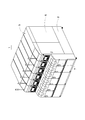
- FIG. 1 is a perspective view showing a processing machine line.
- the processing machine line 1 has a processing machine such as a lathe (hereinafter referred to as “processing module”) 5 that is modularized on a base 2 that is a base.
- processing module 5 is manufactured with the same width, and is mounted so as to be movable in the front-rear direction via a rail laid on the base 2.
- the processing module 5 is a narrow machine tool, and the processing machine line 1 in which the processing modules 5 are arranged close to each other is compact as a whole.
- the processing machine line 1 predetermined processing is performed on the workpiece through the process in each processing module 5. For this reason, the processing machine line 1 is provided with an automatic workpiece transfer machine for transferring workpieces to and from each processing module 5.
- various devices are covered with an exterior cover 6, and a processing chamber for processing a workpiece is provided therein.
- a front cover 7 that can be opened and closed is integrated with the exterior cover 6. The front cover 7 is provided for each processing module 5, but the entire processing machine line 1 constitutes one transfer space, and a workpiece automatic transfer machine for transferring a workpiece is provided therein. Yes.
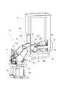
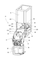
- FIGS. 2 and 3 are perspective views showing the extended state of the articulated robot arm constituting the automatic workpiece transfer machine.
- FIG. 4 is a side view showing the articulated robot arm in a folded state.
- FIG. 5 is a front view of the articulated robot arm 10 in a folded state (right side in FIG. 4), and
- FIG. 6 is a rear view of the articulated robot arm 10 in a folded state.
- the articulated robot arm 10 can move in the transfer space of the front cover 7 in a folded state as shown in FIG. 4, and extends as shown in FIGS.
- the work is delivered between
- the front frame 8 constitutes an inner cover of the processing module 5. That is, the machining module 5 is provided with a spindle chuck for rotating and holding a workpiece, a turret device equipped with a tool, and the like in the inner cover, and the inner cover serves as a machining chamber. Accordingly, the state where the multi-joint robot arm 10 has entered the front frame 8 shows the state when the workpiece is delivered to the spindle chuck.
- the processing module 5 is configured to be compact by reducing the width dimension, and therefore the transport port 801 of the front frame 8 is also narrowed.
- the machining module 5 can machine a large workpiece as compared to the size of the machine body, the articulated robot arm 10 must be capable of inserting a large workpiece into the machining chamber through a narrow frontage. I must.
- the machine module width of the processing module 5 is 450 mm and the width of the transfer port 801 is about 370 mm, whereas the diameter of the workpiece transferred by the articulated robot arm 10 is 300 mm.
- the articulated robot arm 10 is mounted on the traveling device.
- the traveling device is assembled to the front portion of the base 2 located in the front cover 7. That is, a rack or rail is fixed in the horizontal direction at the front portion of the base 2, and a traveling motor that rotates the traveling slider that grips and slides the rail and the pinion that meshes with the rack is mounted on the traveling table 80. Yes. Accordingly, the pinion rack that rotates by driving of the traveling motor rolls, and the traveling table 80 moves along the rail on the front surface portion of the base 2. That is, the articulated robot arm 10 moves in the transfer space formed by the front cover 7.
- the multi-joint robot arm 10 is mounted on the traveling table 80 via a turning table 82.
- a first arm 21 is connected to a support base 25 fixed to a turning table 82 via a first joint mechanism 23, and a second arm 22 is connected to the first arm 21 in the first arm 21.
- the two joint mechanisms 24 are connected.
- the support base 25 includes a pair of parallel support portions 251 standing at a predetermined interval
- the first arm 21 includes a pair of parallel first side plate members 210 arranged at intervals corresponding to the support portions 251. ing. Therefore, the first side plate member 210 is connected to the support portion 251 via the joint shaft, and the angle of the first arm 21 is adjusted by driving the first joint mechanism 23.
- the first arm 21 is assembled so that a space is formed between the pair of first side plate members 210 and the second arm 22 enters therein.
- the second arm 22 includes a pair of parallel second side plate members 220 on the left and right sides, and the second side plate member 220 and the first side plate member 210 are connected by a joint shaft. Therefore, the angle of the second arm 22 relative to the first arm 21 is adjusted by driving the second joint mechanism 24.
- the articulated robot arm 10 has a robot hand 26 attached to the free end side of the second arm 22 that is the tip.
- the robot hand 26 is composed of a pair of chuck devices assembled so as to match each other, and is configured to be able to grip two workpieces W1 and W2 as shown in the figure.
- the robot hand 26 is rotatably attached to the second side plate member 220 via a bearing member so that the position and angle of the pair of chuck devices can be adjusted.
- the robot hand 26 is configured by a chuck device that can grip the workpieces W1 and W2 having a large diameter with respect to the narrow conveyance port 801 of the machining module 5. Therefore, the articulated robot arm 10 has a configuration that allows the first arm 21 and the second arm 22 that support the robot hand 26 to enter with a narrow frontage.
- the articulated robot arm 10 is formed such that the width of the first arm 21 connected to the support base 25 is approximately the same as the width dimension of the processing module 5. That is, the pair of left and right first side plate members 210 constituting the first arm 21 are disposed at substantially the same interval as the width of the front frame 8 as shown in FIG. However, the first arm 21 is stepped so that the width dimension changes, and when viewed in the longitudinal direction (vertical direction in FIG. 6), the spacing on the support base 25 side is wide, and the spacing on the second arm 22 side. Is narrower.
- the pair of first side plate members 210 includes a first wide portion 211 and a first narrow portion 212 formed through a step, and the first arm 21 has the first side plate members 210 arranged symmetrically. And connected together by a back plate 215.
- the first wide portion 211 of the first arm 21 overlaps the front frame 8, but the first narrow width
- the portion 212 is narrower than the conveyance port 801. Therefore, when the articulated robot arm 10 is extended as shown in FIGS. 2 and 3, the first narrow portion 212 of the first arm 21 can enter the machining module 5 (front frame 8). It has become.
- the second arm 22 incorporated inside the first arm 21 is formed with a step so that the width dimension changes in the same manner as the first arm 21.
- the second arm 22 is integrally formed by a pair of left and right second side plate members 220 that are symmetrically connected by a beam member.
- a second narrow portion 221 on the first arm 21 side and a second wide portion 222 on the free end side are formed through a step. Therefore, when viewed in the longitudinal direction (vertical direction in FIG. 5), the second arm 22 has a narrow width on the first arm 21 side and a wide free end side (the tip side of the articulated robot arm 10). ing.
- the second arm 22 When the articulated robot arm 10 is viewed from the front side as shown in FIG. 5, the second arm 22 reaches the position where the second wide portion 222 overlaps the first narrow portion 212 of the first arm 21.
- the width is expanding.
- the articulated robot arm 10 is assembled with a robot hand 26 capable of gripping workpieces W1 and W2 having a large diameter with respect to a pair of second narrow portions 221 whose width is increased.
- the robot can grip a workpiece having a target size.
- the hand 26 can be assembled.
- the articulated robot arm 10 when the articulated robot arm 10 is folded as shown in FIG. 4, the first arm 21 is in an upright posture, and the second arm 22 is in a suspended posture and a part of the first arm 21 is in the first arm 21. Yes.
- the articulated robot arm 10 can be moved in a narrow conveying space in the front cover 7 by being deformed in this compact state.
- the constituent members overlap each other by being folded compactly, it is necessary to prevent the members from interfering with each other.
- the second wide portion 222 of the second arm 22 since the second wide portion 222 of the second arm 22 is in a positional relationship overlapping the first narrow portion 212 of the first arm 21, a drive transmission unit for rotating the robot hand 26 is provided. There was a problem of interference.
- the robot hand 26 has a hand motor at a position hidden behind the cover plate 27 shown in FIG. 5 and is fixed to the second arm 22.
- the rotation output of the hand motor is transmitted to the rotation shaft of the robot hand 26 via a pulley and a belt, and the posture adjustment of the robot hand 26 with respect to the second arm 22 is performed.
- the pulley and belt are housed in a cover case 28. Since the cover case 28 is attached to the second narrow portion 221 of the second arm 22, when the articulated robot arm 10 is initially folded, it interferes with the first narrow portion 212 of the first arm 21. There was a problem.
- the first side plate member 210 of the first arm 21 is formed with a relief portion 217 that is cut out so as to avoid interference with the cover case 28. .
- a member corresponding to the first arm 21 is formed so as to linearly connect the first joint mechanism 23 and the second joint mechanism 24.
- the articulated robot arm 10 has the first arm 21 shown in FIG. 4 due to the first and second side plate members 210 and 220 having steps and the cover case 28 that interferes due to the step shape. Thus, it is formed in a shape bent so as to bend toward the back side.
- the side shape of the first arm 21 is curved to the left in FIG. 4 from the line connecting the first joint mechanism 23 and the second joint mechanism 24 linearly, and the articulated robot arm 10 is on the back side. It has a bulging shape.
- the shape of the articulated robot arm 10 causes another problem. In the processing machine line 1, the conveyance space by the front cover 7 is narrow, and the distance between the articulated robot arm 10 and the front cover 7 is extremely short. Therefore, the articulated robot arm 10 cannot be tilted further from the standing posture shown in FIG. 4 to the back side (left side in the drawing) facing the front cover 7. That is, the state shown in FIG. 4 is the limit angle of the inclination of the articulated robot arm 10 to the back side.
- the articulated robot arm 10 is provided with a reversing device 31 for reversing the workpiece on the back side thereof. Therefore, if the first arm 21 is not tilted toward the reversing device 31 side, that is, the back side, the robot hand 26 cannot be brought close to the reversing device 31 and the workpiece W2 cannot be delivered. Therefore, the side surface of the second arm 22 is generally linear, and is formed in a shape that is bent so as to be curved toward the front side, that is, the processing module 5 side, contrary to the first arm 21. Therefore, in the folded state in which the second arm 22 is suspended downward from the second joint mechanism 24, the free end side is positioned on the back side, and the robot hand 26 approaches the position where the workpiece can be delivered to the reversing device 31. It has become.
- the articulated robot arm 10 of this embodiment can be equipped with a robot hand 26 for gripping a workpiece having a large diameter by forming the first arm 21 and the second arm 22 with a stepped shape.
- a robot hand 26 for gripping a workpiece having a large diameter by forming the first arm 21 and the second arm 22 with a stepped shape.
- the diameter can be increased by increasing the width by the second wide portion 222 of the second arm 22 while allowing the first narrow portion 212 of the first arm 21 to enter the front frame 8.
- the robot hand 26 that holds a large workpiece can be mounted.
- the articulated robot arm 10 can transport a relatively large workpiece to the processing module 5 designed to be compact.
- the articulated robot arm 10 forms a relief portion 217 in the first side plate member 210 to prevent interference between the members, while the first side plate member 210 is bent so as to bend toward the back side. As a result, the rigidity of the first side plate member 210 can be secured by increasing the width.
- the second arm 22 is similarly bent so that the second side plate member 220 is bent, so that the robot hand 26 can deliver the workpiece to the reversing device 31.
Landscapes
- Engineering & Computer Science (AREA)
- Robotics (AREA)
- Mechanical Engineering (AREA)
- Manipulator (AREA)
Abstract
ワークに比して狭い間口を通すことができるように、幅方向に所定の間隔でベース部材に立設された一対の支持部(251)と、前記一対の支持部に対して第1関節によって回転支持され、前記第1 関節とは反対の端部側の間隔が幅方向内側に狭くなる段差を備えた一対の第1側板部材(210)によって形成された第1アーム(21)と、前記一対の第1側板部材の内側に配置され、前記第1側板部材に対し第2関節によって回転支持され、前記第2関節とは反対の端部側の間隔が幅方向外側に広くなる段差を備えた一対の第2側板部材(220)によって形成された第2アーム(22)と、前記第2アームに対して前記第2関節とは反対側の先端部分に組み付けられたロボットハンド(26)とを有する多関節ロボットアーム。
Description
本発明は、ワークに比して狭い間口を通すようにした多関節ロボットアームに関する。
複数の加工機械からなる加工機械ラインでは、1列に配置された複数の加工機械の間をワークが順番に送られ、各々の加工機械において加工処理や検測処理など所定の処理が実行される。下記特許文献1には、加工機械の間でワークの受渡しをするためのワーク自動搬送機が開示されている。具体的には、加工機械の前を移動可能に組み付けられた搬送ロボットである。複数の加工機械を搭載した架台の前部に搬送用レールが固定され、そこに走行台が移動可能に設けられ、その走行台の上にワークの受渡しを行うための多関節ロボットアームが搭載されている。
特許文献1に記載の多関節ロボットアームは、関節を介して複数のアームが折りたたまれた状態と伸びた状態とに変化するものであるが、先端のロボットハンドで把持することができるワークは比較的小さいものであると考えられる。しかし、搬送機としての多関節ロボットアームは、扱うワークに様々なものがあり、大型ワークの取り扱いも求められている。一方で、近年は加工機械がコンパクトになってきており、多関節ロボットアームにおける間口の狭い空間での作業要求も高まっている。また、ワークを搬送させる搬送スペースも狭小化しており、多関節ロボットアーム自体もコンパクトであることなどが求められている。
そこで、本発明は、かかる課題を解決すべく、ワークに比して狭い間口を通すようにした多関節ロボットアームを提供することを目的とする。
本発明の一態様における多関節ロボットアームは、幅方向に所定の間隔でベース部材に立設された一対の支持部と、前記一対の支持部に対して第1関節によって回転支持され、前記第1関節とは反対の端部側の間隔が幅方向内側に狭くなる段差を備えた一対の第1側板部材によって形成された第1アームと、前記一対の第1側板部材の内側に配置され、前記第1側板部材に対し第2関節によって回転支持され、前記第2関節とは反対の端部側の間隔が幅方向外側に広くなる段差を備えた一対の第2側板部材によって形成された第2アームと、前記第2アームに対して前記第2関節とは反対側の先端部分に組み付けられたロボットハンドとを有する。
前記開示の構成によれば、段差を備えた一対の第1側板部材によって形成された第1アームは、幅方向内側に狭くなった部分が加工機械内に入り込み、その第1アームの内側に配置された第2側板部材により形成された第2アームは、幅方向外側に広くなった部分にロボットハンドが搭載されているので、ワークに比して狭い間口を通すことができる。
次に、本発明に係る多関節ロボットアームの一実施形態について、図面を参照しながら以下に説明する。本実施形態の多関節ロボットアームは、複数の工作機械からなる加工機械ラインのワーク自動搬送機を構成するものであり、各々の工作機械との間でワークの受渡しを行うものである。図1は、加工機械ラインを示した斜視図である。
この加工機械ライン1は、図示するように6台の工作機械5が幅方向並べられ、互いに近接して配置されている。加工機械ライン1は、基礎となるベース2の上にモジュール化された旋盤などの加工機械(以下、「加工モジュール」という)5が搭載されている。各々の加工モジュール5は、いずれも同じ幅寸法で製造されたものであり、ベース2の上に敷設されたレールを介して前後方向に移動可能な状態で搭載されている。加工モジュール5は幅の狭い工作機械であり、それらが近接して配置された加工機械ライン1は、全体的にコンパクトなものになっている。
加工機械ライン1では、各々の加工モジュール5における工程を経てワークに対して所定の加工が行われる。そのため、加工機械ライン1には、各加工モジュール5との間でワークの受渡しを行うためのワーク自動搬送機が設けられている。加工モジュール5は、各種装置が外装カバー6によって覆われ、その内部にワークを加工するための加工室が設けられている。そして、外装カバー6には開閉可能な前カバー7が一体になって構成されている。この前カバー7は、加工モジュール5毎に設けられているが、加工機械ライン1全体では一つの搬送空間を構成しており、その中にワークを搬送するためのワーク自動搬送機が設けられている。
次に、図2及び図3は、ワーク自動搬送機を構成する多関節ロボットアームの伸びた状態を示した斜視図である。図4は、折り畳まれた状態の多関節ロボットアームを示した側面図である。そして、図5は、折り畳まれた状態の多関節ロボットアーム10の正面図(図4の右側)であり、図6は、折り畳まれた状態の多関節ロボットアーム10の背面図である。この多関節ロボットアーム10は、図4に示すように折り畳まれた状態で前カバー7の搬送空間内を移動することができ、図2及び図3に示すように伸びることで各加工モジュール5との間でワークの受渡しが行われるようになっている
図2及び図3では、加工モジュール5の前部フレーム8内に入った状態が示されている。この前部フレーム8は、加工モジュール5の内部カバーを構成するものである。つまり、加工モジュール5は、ワークを回転保持する主軸チャックや工具を備えたタレット装置などが内部カバー内に設けられ、その内部カバーが加工室となっている。従って、多関節ロボットアーム10が前部フレーム8に進入した状態は、主軸チャックとのワークの受渡し時の状態が示されている。
前述したように、加工モジュール5は幅寸法を小さくしてコンパクトに構成されたものであり、そのため前部フレーム8の搬送口801も狭くなっている。しかし、加工モジュール5では、その機体サイズに比して大型のワークを加工することができるため、多関節ロボットアーム10は、狭い間口を通して大型のワークを加工室奥まで挿入できるようなものでなければならない。例えば本実施形態では、加工モジュール5の機体幅が450mmであり、搬送口801の幅が370mm程度あるのに対して、多関節ロボットアーム10が搬送するワークの径が300mmである。
加工機械ライン1のワーク自動搬送機は、多関節ロボットアーム10が走行装置に搭載されている。その走行装置は、前カバー7内に位置するベース2の前部に組み付けられている。すなわち、ベース2の前部には水平方向にラックやレールが固定され、走行台80にはレールを掴んで摺動する走行スライダやラックに噛合したピニオンに回転を与える走行用モータが搭載されている。よって、走行用モータの駆動により回転するピニオンラックを転動し、走行台80がレールに沿ってベース2の前面部を移動する。すなわち、多関節ロボットアーム10が、前カバー7により構成されている搬送空間内を移動することになる。
多関節ロボットアーム10は、旋回テーブル82を介して走行台80上に搭載されている。その多関節ロボットアーム10は、旋回テーブル82に固定された支持台25に対し、第1アーム21が第1関節機構23を介して連結され、更に第1アーム21には第2アーム22が第2関節機構24を介して連結されている。支持台25は、一対の平行な支持部251が所定の間隔で起立し、第1アーム21は、その支持部251に対応する間隔で配置された一対の平行な第1側板部材210により構成されている。従って、第1側板部材210が支持部251に対して関節軸を介して連結され、第1関節機構23の駆動により第1アーム21の角度調整が行われるようになっている。
第1アーム21は、一対の第1側板部材210の間に空間が形成され、第2アーム22がその中に入り込むよう組み付けられている。第2アーム22は、左右に一対の平行な第2側板部材220により構成され、その第2側板部材220と第1側板部材210が関節軸によって連結されている。従って、第2アーム22は、第2関節機構24の駆動により、第1アーム21に対する角度調整が行われるようになっている。そして、多関節ロボットアーム10は、その先端部となる第2アーム22の自由端側にロボットハンド26が取り付けられている。
ロボットハンド26は、背を合わせるように組み付けられた一対のチャック装置によって構成され、図示するように2つのワークW1,W2を把持することができるように構成されている。そのロボットハンド26は、第2側板部材220との間に軸受部材を介して回転可能に取り付けられ、一対のチャック装置の位置や角度の姿勢調整が可能になっている。ロボットハンド26は、前述したように加工モジュール5の幅の狭い搬送口801に対して径の大きなワークW1,W2を把持することが可能なチャック装置によって構成されている。そこで、多関節ロボットアーム10は、そのロボットハンド26を支持する第1アーム21や第2アーム22に、狭い間口での進入を可能にした構成がとられている。
多関節ロボットアーム10は、支持台25に連結された第1アーム21の幅が加工モジュール5の幅寸法と同程度の大きさで形成されている。すなわち、第1アーム21を構成する左右一対の第1側板部材210が、図6に示すように前部フレーム8の幅とほぼ同じ間隔で配置されている。しかし、第1アーム21は、幅寸法が変化するように段差が形成され、長手方向(図6の上下方向)に見た場合に支持台25側の間隔が広く、第2アーム22側の間隔が狭くなっている。すなわち、一対の第1側板部材210は、第1幅広部211と第1幅狭部212とが段差を介して形成され、第1アーム21は、その第1側板部材210同士が対称的に配置され、背面板215によって連結されて一体になっている。
従って、多関節ロボットアーム10を図6に示す背面側から見た場合、その第1アーム21は、第1幅広部211の部分は前部フレーム8に重なってしまっているが、第1幅狭部212の部分は搬送口801より幅が狭くなっている。そのため、多関節ロボットアーム10は、図2及び図3に示すように伸びた状態では、第1アーム21の第1幅狭部212部分が加工モジュール5(前部フレーム8)内に進入可能になっている。
次に、第1アーム21の内側に組み込まれている第2アーム22は、第1アーム21と同じように、幅寸法が変化するように段差が形成されている。第2アーム22は、左右一対の第2側板部材220が梁部材によって対称的に連結されて一体になっている。その第2側板部材220は、第1アーム21側の第2幅狭部221と自由端側の第2幅広部222とが段差を介して形成されている。そのため、第2アーム22は、長手方向(図5の上下方向)に見た場合に第1アーム21側の幅が狭く、自由端側(多関節ロボットアーム10の先端側)の幅が広くなっている。
多関節ロボットアーム10を図5に示すように前側から見た場合、第2アーム22は、第2幅広部222の部分が第1アーム21の第1幅狭部212の部分に重なる位置にまで幅が広がっている。そして、多関節ロボットアーム10は、その幅を広くした一対の第2幅狭部221に対し、大きな径のワークW1,W2を把持することができるロボットハンド26が組み付けられている。このように、第2アーム22は、幅が狭い第2幅狭部221部分から第2幅広部222部分へと幅が広がっているため、目標とする大きさのワークを把持することができるロボットハンド26の組付けが可能になっている。
ところで、多関節ロボットアーム10は、図4に示すように折り畳まれた場合、第1アーム21は起立姿勢になり、第2アーム22が垂れ下がった姿勢で第1アーム21内に一部が収まっている。多関節ロボットアーム10は、このようにコンパクトな状態に変形することで、狭い前カバー7内の搬送空間を移動することが可能になる。しかし、コンパクトに折り畳むことで構成部材同士が重なってしまうため、その部材同士が互いに干渉しないようにする必要がある。例えば、本実施形態では、第2アーム22の第2幅広部222が第1アーム21の第1幅狭部212に重なる位置関係にあるので、ロボットハンド26を回転駆動させるための駆動伝達部が干渉してしまう問題があった。
ロボットハンド26は、図5に示すカバープレート27に隠れた位置にハンド用モータがあり、第2アーム22に固定されている。そのハンド用モータの回転出力は、プーリやベルトを介してロボットハンド26の回転軸に伝達され、第2アーム22に対するロボットハンド26の姿勢調整が行われるようになっている。図面ではそのプーリやベルトはカバーケース28内に収められている。そして、このカバーケース28が第2アーム22の第2幅狭部221に取り付けられているため、当初、多関節ロボットアーム10が折り畳まれると、第1アーム21の第1幅狭部212と干渉してしまう問題があった。
そこで本実施形態では、このような解題を解決すべく、第1アーム21の第1側板部材210に対し、カバーケース28との干渉を避けるように切り欠かれた逃げ部217が形成されている。通常、第1アーム21に相当する部材は、第1関節機構23と第2関節機構24とを直線的に結ぶように形成される。しかし、多関節ロボットアーム10は、段差を持った第1及び第2側板部材210,220や、その段差形状のため干渉してしまうカバーケース28などにより、第1アーム21は、図4に示すように背面側に湾曲するように折れ曲がった形状で形成されている。
こうして、本実施形態では、第1アーム21の側面形状が第1関節機構23と第2関節機構24とを直線的に結ぶ線より図4の左側に湾曲し、多関節ロボットアーム10が背面側に膨らんだ形状となっている。しかし、こうした多関節ロボットアーム10の形状としたことで別の課題が生じることにもなった。加工機械ライン1では、前カバー7による搬送空間が狭く、多関節ロボットアーム10と前カバー7との距離が極めて近い。そのため、多関節ロボットアーム10は、図4に示す起立姿勢から更に前カバー7に面している背面側(図面左側)には傾けられない。つまり、図4に示す状態が、多関節ロボットアーム10の背面側への傾きのほぼ限界角度である。
ところで、多関節ロボットアーム10には、その背面側にワークを反転させる反転装置31が設けられている。そのため、第1アーム21が反転装置31側つまり背面側に傾けられないと、ロボットハンド26を反転装置31に近づけることができず、ワークW2を受け渡しすることができなくなってしまう。そこで、第2アーム22の側面形状は、一般的には直線形状になるところ、第1アーム21とは逆に前方側つまり加工モジュール5側に湾曲するように折れ曲がった形状で形成されている。よって、第2アーム22は、第2関節機構24から下方に吊下げられた折り畳み状態では自由端側が背面側に位置し、ロボットハンド26が反転装置31とのワーク受渡しが可能な位置まで近づくようになっている。
従って、本実施形態の多関節ロボットアーム10は、第1アーム21と第2アーム22とを段差の付いた形状にしたことにより、径の大きなワークを把持するためのロボットハンド26の搭載を可能にしつつも、狭い幅の搬送口801への進入が可能になった。具体的には、第1アーム21の第1幅狭部212部分によって前部フレーム8内への進入を可能にしつつ、第2アーム22の第2幅広部222によって幅を広げることで、径の大きなワークを把持するロボットハンド26の搭載が可能になった。そして、多関節ロボットアーム10は、コンパクトに設計された加工モジュール5に対して比較的大きなワークの搬送を行うことが可能になった。
また、多関節ロボットアーム10は、第1側板部材210に逃げ部217を形成して部材同士の干渉を防止する一方で、その第1側板部材210を背面側に湾曲するように折れ曲がった形状にしたことで、第1側板部材210の幅を広くとることにより剛性を確保することができた。そして、第2アーム22は、同じように第2側板部材220を湾曲するように折れ曲がった形状にすることでロボットハンド26が反転装置31とのワーク受渡しが可能になった。
以上、本発明の一実施形態について説明したが、本発明はこれらに限定されるものではなく、その趣旨を逸脱しない範囲で様々な変更が可能である。
例えば、前記実施形態では、加工モジュール5の機体幅や搬送口801大きさ、そしてワークの径について具体的な数値を示したが、これは一例である。
例えば、前記実施形態では、加工モジュール5の機体幅や搬送口801大きさ、そしてワークの径について具体的な数値を示したが、これは一例である。
1…加工機械ライン 5…加工モジュール 7…前カバー 8…前部フレーム 10…多関節ロボットアーム 21…第1アーム 22…第2アーム 23…第1関節機構 24…第2関節機構 25…支持台 26…ロボットハンド 210…第1側板部材 211…第1幅広部 212…第1幅狭部 217…逃げ部 220…第2側板部材 221…第2幅狭部 222…第2幅広部 801…搬送口
Claims (4)
- 幅方向に所定の間隔でベース部材に立設された一対の支持部と、
前記一対の支持部に対して第1関節によって回転支持され、前記第1関節とは反対の端部側の間隔が幅方向内側に狭くなる段差を備えた一対の第1側板部材によって形成された第1アームと、
前記一対の第1側板部材の内側に配置され、前記第1側板部材に対し第2関節によって回転支持され、前記第2関節とは反対の端部側の間隔が幅方向外側に広くなる段差を備えた一対の第2側板部材によって形成された第2アームと、
前記第2アームに対して前記第2関節とは反対側の先端部分に組み付けられたロボットハンドと
を有する多関節ロボットアーム。 - 前記一対の第1側板部材における幅方向の間隔が狭い部分と、前記一対の第2側板部材における幅方向の間隔が広い部分とが、前記第2関節によって前記第2側板部材が揺動する方向に見て重なる位置に組み付けられた請求項1に記載の多関節ロボットアーム。
- 前記一対の第2側板部材における幅方向の間隔が狭い部分が、前記一対の第1側板部材における幅方向の間隔が広い部分に入り込むようにした請求項1又は請求項2に記載の多関節ロボットアーム。
- 前記第1アームと前記第2アームは、前記第1関節および第2関節の平行な関節軸の軸方向に沿って横方向から見た場合に、前記第1側板部材と前記第2側板部材とは逆方向に湾曲した形状で形成されたものである請求項1乃至請求項3のいずれかに記載の多関節ロボットアーム。
Priority Applications (4)
| Application Number | Priority Date | Filing Date | Title |
|---|---|---|---|
| CN201680091095.XA CN110023042B (zh) | 2016-11-29 | 2016-11-29 | 多关节机器人手臂 |
| US16/347,304 US11059167B2 (en) | 2016-11-29 | 2016-11-29 | Multi-joint robot arm |
| PCT/JP2016/085417 WO2018100644A1 (ja) | 2016-11-29 | 2016-11-29 | 多関節ロボットアーム |
| JP2018553548A JP6661031B2 (ja) | 2016-11-29 | 2016-11-29 | 多関節ロボットアーム |
Applications Claiming Priority (1)
| Application Number | Priority Date | Filing Date | Title |
|---|---|---|---|
| PCT/JP2016/085417 WO2018100644A1 (ja) | 2016-11-29 | 2016-11-29 | 多関節ロボットアーム |
Publications (1)
| Publication Number | Publication Date |
|---|---|
| WO2018100644A1 true WO2018100644A1 (ja) | 2018-06-07 |
Family
ID=62241284
Family Applications (1)
| Application Number | Title | Priority Date | Filing Date |
|---|---|---|---|
| PCT/JP2016/085417 Ceased WO2018100644A1 (ja) | 2016-11-29 | 2016-11-29 | 多関節ロボットアーム |
Country Status (4)
| Country | Link |
|---|---|
| US (1) | US11059167B2 (ja) |
| JP (1) | JP6661031B2 (ja) |
| CN (1) | CN110023042B (ja) |
| WO (1) | WO2018100644A1 (ja) |
Citations (7)
| Publication number | Priority date | Publication date | Assignee | Title |
|---|---|---|---|---|
| JP2001516288A (ja) * | 1997-04-01 | 2001-09-25 | カイララー、チャールズ | モジュール化された関節ロボット構造体 |
| JP2009050939A (ja) * | 2007-08-24 | 2009-03-12 | Nsk Ltd | リンク機構及び脚車輪型ロボット |
| JP2011104752A (ja) * | 2009-11-20 | 2011-06-02 | Thk Co Ltd | ロボットの関節構造、ロボットフィンガー及びロボットハンド |
| JP2012232361A (ja) * | 2011-04-28 | 2012-11-29 | Seiko Epson Corp | ロボット |
| JP2013071231A (ja) * | 2011-09-29 | 2013-04-22 | Panasonic Corp | ロボットアームの教示装置、ロボット装置、教示方法、ロボットアームの制御装置、ロボットアームの制御プログラム、並びに、集積電子回路 |
| WO2013099104A1 (ja) * | 2011-12-28 | 2013-07-04 | パナソニック株式会社 | ロボットアーム |
| WO2015145576A1 (ja) * | 2014-03-25 | 2015-10-01 | 富士機械製造株式会社 | 多関節ロボットアーム |
Family Cites Families (5)
| Publication number | Priority date | Publication date | Assignee | Title |
|---|---|---|---|---|
| JP2010155300A (ja) | 2008-12-26 | 2010-07-15 | Mitsubishi Heavy Ind Ltd | 工作機械 |
| JP5159994B1 (ja) * | 2012-04-20 | 2013-03-13 | 三菱電機株式会社 | ロボット関節構造 |
| CN205033237U (zh) * | 2015-09-30 | 2016-02-17 | 北京恒正精机科技有限责任公司 | 一种多自由度机械臂 |
| WO2017146404A1 (ko) * | 2016-02-26 | 2017-08-31 | 고려대학교 산학협력단 | 중력보상장치를 구비한 수직다관절 로봇 머니퓰레이터 |
| CN106625755A (zh) * | 2016-08-31 | 2017-05-10 | 常州高思科技有限公司 | 径向错位以增大机械臂臂体间活动范围的方法及其机械臂 |
-
2016
- 2016-11-29 US US16/347,304 patent/US11059167B2/en not_active Expired - Fee Related
- 2016-11-29 JP JP2018553548A patent/JP6661031B2/ja active Active
- 2016-11-29 WO PCT/JP2016/085417 patent/WO2018100644A1/ja not_active Ceased
- 2016-11-29 CN CN201680091095.XA patent/CN110023042B/zh not_active Expired - Fee Related
Patent Citations (7)
| Publication number | Priority date | Publication date | Assignee | Title |
|---|---|---|---|---|
| JP2001516288A (ja) * | 1997-04-01 | 2001-09-25 | カイララー、チャールズ | モジュール化された関節ロボット構造体 |
| JP2009050939A (ja) * | 2007-08-24 | 2009-03-12 | Nsk Ltd | リンク機構及び脚車輪型ロボット |
| JP2011104752A (ja) * | 2009-11-20 | 2011-06-02 | Thk Co Ltd | ロボットの関節構造、ロボットフィンガー及びロボットハンド |
| JP2012232361A (ja) * | 2011-04-28 | 2012-11-29 | Seiko Epson Corp | ロボット |
| JP2013071231A (ja) * | 2011-09-29 | 2013-04-22 | Panasonic Corp | ロボットアームの教示装置、ロボット装置、教示方法、ロボットアームの制御装置、ロボットアームの制御プログラム、並びに、集積電子回路 |
| WO2013099104A1 (ja) * | 2011-12-28 | 2013-07-04 | パナソニック株式会社 | ロボットアーム |
| WO2015145576A1 (ja) * | 2014-03-25 | 2015-10-01 | 富士機械製造株式会社 | 多関節ロボットアーム |
Also Published As
| Publication number | Publication date |
|---|---|
| US11059167B2 (en) | 2021-07-13 |
| JPWO2018100644A1 (ja) | 2019-07-18 |
| CN110023042B (zh) | 2022-04-29 |
| US20190283238A1 (en) | 2019-09-19 |
| CN110023042A (zh) | 2019-07-16 |
| JP6661031B2 (ja) | 2020-03-11 |
Similar Documents
| Publication | Publication Date | Title |
|---|---|---|
| JP6438937B2 (ja) | 多関節ロボットアーム | |
| KR102662204B1 (ko) | 공작기계 | |
| JP2017202547A (ja) | 工作機械 | |
| WO2019039592A1 (ja) | 曲げ加工装置 | |
| CN110545952B (zh) | 机器人系统和具备该机器人系统的工作线 | |
| CN108526970A (zh) | 机床 | |
| JP7005136B2 (ja) | 把持装置、ロボット装置、制御方法、制御プログラム、記録媒体、および物品の製造方法 | |
| TW201617192A (zh) | 機器人及機器人系統 | |
| JP2018001364A (ja) | 工作機械ユニット | |
| US20210387354A1 (en) | Automatic workpiece carrying machine | |
| JP2008307650A (ja) | ワーク供給搬出装置 | |
| JP6517782B2 (ja) | ワーク自動搬送機 | |
| KR101863150B1 (ko) | 용접 장치 | |
| JP6661031B2 (ja) | 多関節ロボットアーム | |
| WO2018100693A1 (ja) | 工作機械および加工機械ライン | |
| WO2022097411A1 (ja) | ハンド及びハンドの制御方法 | |
| JP6634088B2 (ja) | 多関節ロボットアーム | |
| JP2005066762A (ja) | 搬送用ロボット | |
| JP6837571B2 (ja) | 設置型小型モジュールおよび加工機械ライン | |
| JP7041747B2 (ja) | ワーク自動搬送機 | |
| JP7568102B2 (ja) | 対向二軸型旋盤 | |
| JP6876198B2 (ja) | 工作機械 | |
| JP7302387B2 (ja) | 加工システム | |
| JP2020124774A (ja) | ワーク受渡し構造 | |
| JP2012206182A (ja) | ワーク搬送装置 |
Legal Events
| Date | Code | Title | Description |
|---|---|---|---|
| 121 | Ep: the epo has been informed by wipo that ep was designated in this application |
Ref document number: 16923114 Country of ref document: EP Kind code of ref document: A1 |
|
| ENP | Entry into the national phase |
Ref document number: 2018553548 Country of ref document: JP Kind code of ref document: A |
|
| NENP | Non-entry into the national phase |
Ref country code: DE |
|
| 122 | Ep: pct application non-entry in european phase |
Ref document number: 16923114 Country of ref document: EP Kind code of ref document: A1 |