WO2018097230A1 - ロボット制御装置および同制御装置を備えたロボット - Google Patents
ロボット制御装置および同制御装置を備えたロボット Download PDFInfo
- Publication number
- WO2018097230A1 WO2018097230A1 PCT/JP2017/042164 JP2017042164W WO2018097230A1 WO 2018097230 A1 WO2018097230 A1 WO 2018097230A1 JP 2017042164 W JP2017042164 W JP 2017042164W WO 2018097230 A1 WO2018097230 A1 WO 2018097230A1
- Authority
- WO
- WIPO (PCT)
- Prior art keywords
- energization
- control device
- robot
- excitation
- brake
- Prior art date
- Legal status (The legal status is an assumption and is not a legal conclusion. Google has not performed a legal analysis and makes no representation as to the accuracy of the status listed.)
- Ceased
Links
Images


Classifications
-
- H—ELECTRICITY
- H02—GENERATION; CONVERSION OR DISTRIBUTION OF ELECTRIC POWER
- H02P—CONTROL OR REGULATION OF ELECTRIC MOTORS, ELECTRIC GENERATORS OR DYNAMO-ELECTRIC CONVERTERS; CONTROLLING TRANSFORMERS, REACTORS OR CHOKE COILS
- H02P3/00—Arrangements for stopping or slowing electric motors, generators, or dynamo-electric converters
- H02P3/02—Details of stopping control
- H02P3/04—Means for stopping or slowing by a separate brake, e.g. friction brake or eddy-current brake
-
- B—PERFORMING OPERATIONS; TRANSPORTING
- B25—HAND TOOLS; PORTABLE POWER-DRIVEN TOOLS; MANIPULATORS
- B25J—MANIPULATORS; CHAMBERS PROVIDED WITH MANIPULATION DEVICES
- B25J19/00—Accessories fitted to manipulators, e.g. for monitoring, for viewing; Safety devices combined with or specially adapted for use in connection with manipulators
- B25J19/0004—Braking devices
-
- F—MECHANICAL ENGINEERING; LIGHTING; HEATING; WEAPONS; BLASTING
- F16—ENGINEERING ELEMENTS AND UNITS; GENERAL MEASURES FOR PRODUCING AND MAINTAINING EFFECTIVE FUNCTIONING OF MACHINES OR INSTALLATIONS; THERMAL INSULATION IN GENERAL
- F16D—COUPLINGS FOR TRANSMITTING ROTATION; CLUTCHES; BRAKES
- F16D27/00—Magnetically- or electrically- actuated clutches; Control or electric circuits therefor
- F16D27/004—Magnetically- or electrically- actuated clutches; Control or electric circuits therefor with permanent magnets combined with electromagnets
-
- B—PERFORMING OPERATIONS; TRANSPORTING
- B25—HAND TOOLS; PORTABLE POWER-DRIVEN TOOLS; MANIPULATORS
- B25J—MANIPULATORS; CHAMBERS PROVIDED WITH MANIPULATION DEVICES
- B25J19/00—Accessories fitted to manipulators, e.g. for monitoring, for viewing; Safety devices combined with or specially adapted for use in connection with manipulators
-
- B—PERFORMING OPERATIONS; TRANSPORTING
- B25—HAND TOOLS; PORTABLE POWER-DRIVEN TOOLS; MANIPULATORS
- B25J—MANIPULATORS; CHAMBERS PROVIDED WITH MANIPULATION DEVICES
- B25J9/00—Program-controlled manipulators
- B25J9/10—Program-controlled manipulators characterised by positioning means for manipulator elements
- B25J9/12—Program-controlled manipulators characterised by positioning means for manipulator elements electric
-
- H—ELECTRICITY
- H02—GENERATION; CONVERSION OR DISTRIBUTION OF ELECTRIC POWER
- H02P—CONTROL OR REGULATION OF ELECTRIC MOTORS, ELECTRIC GENERATORS OR DYNAMO-ELECTRIC CONVERTERS; CONTROLLING TRANSFORMERS, REACTORS OR CHOKE COILS
- H02P15/00—Arrangements for controlling dynamo-electric brakes or clutches
Definitions
- the present invention relates to a robot control device for controlling a robot having a servo motor with a non-excitation operation type electromagnetic brake and a robot having the same control device.
- Servo motors used for the drive shafts of robots, especially industrial robot arms in addition to the certainty of holding the position at the time of stop, etc., in order to prevent runaway at the time of power loss etc. during operation,
- a non-excitation actuating electromagnetic brake hereinafter sometimes simply referred to as “brake”.
- the non-excitation actuated electromagnetic brake has an exciting coil, a spring, an armature and a friction plate arranged in a line in this order, and when the excitation coil is not energized, the armature is pressed against the friction plate by the biasing force of the spring, When the exciting coil is energized, the brake operating state is released by attracting the armature against the biasing force of the spring and pulling it away from the friction plate.
- the energization to the excitation coil is started in the brake operation state, and after the armature is separated from the friction plate to the brake release position, the energization state to the excitation coil is not always maintained. I know I don't have to.
- the brake release state can be maintained even if the energization to the excitation coil is stopped for a short time. it can.
- the energization stoptable time during which the brake release state can be maintained differs depending on the brake specifications.
- Patent Document 1 discloses ON / OFF control of power supply to the excitation coil in the brake release state in order to suppress heat generation due to energization of the excitation coil in the brake release state. Techniques to do this have been proposed.
- noise is generated when energization of the excitation coil is started (energization ON) and when the energization of the excitation coil is interrupted (energization OFF). Therefore, it is necessary to reduce the influence of this noise on peripheral devices as much as possible. .
- a larger noise is generated when the energization is turned on than when the energization is turned off.
- Patent Document 1 Although an effect of suppressing heat generation and energy saving can be expected by performing ON / OFF control of energization to the exciting coil in the brake release state, it can be used for peripheral devices due to noise generated during ON / OFF control. A new problem of adverse effects occurs.
- the present invention has been made in view of the above-mentioned problems of the prior art, and is a robot control capable of realizing heat generation suppression and energy saving while suppressing generation of noise in a non-excitation operation type electromagnetic brake of the robot. It is an object of the present invention to provide a device and a robot equipped with the control device.
- a first aspect of the present invention is a control device for a robot having a drive shaft driven by a servo motor provided with a non-excitation operation type electromagnetic brake, wherein the non-excitation operation type electromagnetic In the brake release state of the brake, the energization ON and the energization OFF of the excitation coil of the non-excitation operation type electromagnetic brake are alternately repeated, and at this time, at least the timing of the energization ON is shifted among the plurality of excitation coils. It is comprised in that.
- both the energization ON timing and the energization OFF timing are configured to be shifted between the plurality of excitation coils. To do.
- a third aspect of the present invention is characterized in that, in the first or second aspect, it is configured to modulate an ON / OFF ratio of the energization ON and the energization OFF.
- a fourth aspect of the present invention is characterized in that, in the third aspect, the ON / OFF ratio is modulated at random.
- a fifth aspect of the present invention is characterized in that, in any one of the first to fourth aspects, the switching frequency of the energization ON and the energization OFF is modulated.
- the sixth aspect of the present invention is characterized in that, in the fifth aspect, the switching frequency is modulated at random.
- a seventh aspect of the present invention is a robot including the robot control device according to any one of the first to sixth aspects and a drive shaft controlled by the robot control device.
- a robot control device capable of suppressing heat generation and energy saving while suppressing generation of noise in a non-excitation operation type electromagnetic brake of the robot, and a robot including the control device.
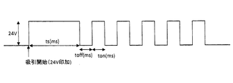
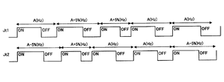
- the figure for demonstrating the voltage signal applied to an exciting coil in the brake system shown in FIG. The figure which showed an example of the voltage signal applied to an exciting coil in the brake system shown in FIG.
- the brake system in the robot includes a non-excitation operation type electromagnetic brake 1 incorporated in a servo motor.
- this brake system by supplying a timing control signal from the robot controller 2 to a switching element to which a predetermined voltage (24 V in this example) is supplied and switching it, the energization of the excitation coil of the brake 1 is turned on. It is configured to switch between the state and the energization OFF state.
- the suction time ts (ms), voltage application DUTY (%) after suction, and frequency are arbitrarily set according to the motor characteristics (suction time, release time, etc.). can do.
- the non-excitation actuating electromagnetic brake 1 has an exciting coil, a spring, an armature, and a friction plate arranged in this order in the same manner as described in the prior art section, and when the exciting coil is not energized.
- the armature is pressed against the friction plate by the urging force of the spring, and the brake operation is performed. It is a thing to cancel.
- the non-excitation operation type electromagnetic brake 1 is provided on each of a plurality of drive shafts of the robot.
- the switching element When switching the non-excitation operation type electromagnetic brake 1 in the brake operation state to the brake release state, the switching element is turned on by the timing control signal from the robot control device 2, and a predetermined voltage (In this example, 24V) is applied to the exciting coil of the brake 1, the armature is sucked and separated from the friction plate, and the brake operating state is released.
- a predetermined voltage In this example, 24V
- the following measures are taken in order to suppress adverse effects on peripheral devices due to noise generated by ON / OFF control of energization to the exciting coil.
- the non-excitation actuated electromagnetic brake 1 when the non-excitation actuated electromagnetic brake 1 is in the brake release state, when the energization ON and the energization OFF of the excitation coil of the brake 1 are alternately repeated, a plurality of drive shafts are provided.
- the energization ON timing and the energization OFF timing are configured to deviate between the excitation coils.
- the energization ON timing and the energization OFF timing are shifted between the plurality of exciting coils at all timings.
- FIG. 3 is a diagram showing an example of a voltage signal applied to the exciting coil in the brake release state in the brake system shown in FIG.
- the energization ON and energization OFF timings are all deviated between the three excitation coils of the three drive shafts (Jt1, Jt2, Jt3) of the robot.
- the timing of energization ON and energization to the plurality of excitation coils in the brake release state differs for each excitation coil, and therefore the noise generation timing during the ON / OFF operation is different. Different for each exciting coil, it is possible to avoid the simultaneous occurrence of noise and to suppress the adverse effects of noise on peripheral devices.
- the ON / OFF ratio (DUTY) of energization ON and energization OFF is randomly modulated with a constant period.
- the switching frequency of energization ON and energization OFF may be randomly modulated as shown in FIG.
- the noise generation timing during ON / OFF operation differs for each excitation coil, and the noise Generation
- the ON / OFF ratio is fixed.
- the switching frequency of energization ON and energization OFF is randomly modulated, and the ON / OFF ratio is also random. You may make it modulate. Thereby, it can be expected that the spectrum spread effect of the harmonic noise is increased.
Landscapes
- Engineering & Computer Science (AREA)
- Mechanical Engineering (AREA)
- Robotics (AREA)
- General Engineering & Computer Science (AREA)
- Power Engineering (AREA)
- Physics & Mathematics (AREA)
- Electromagnetism (AREA)
- Braking Arrangements (AREA)
- Manipulator (AREA)
- Regulating Braking Force (AREA)
Abstract
無励磁作動型電磁ブレーキ(1)を備えたサーボモータにより駆動される駆動軸を有するロボットの制御装置(2)であって、無励磁作動型電磁ブレーキ(1)のブレーキ解除状態において、無励磁作動型電磁ブレーキ(1)の励磁コイルへの通電ONと通電OFFとを交互に繰り返し、その際、複数の励磁コイルの間で少なくとも通電ONのタイミングがずれるように構成されている。ロボットの無励磁作動型電磁ブレーキにおけるノイズの発生を抑制しつつ、発熱抑制・省エネを実現できる。
Description
本発明は、無励磁作動型電磁ブレーキ付きのサーボモータを備えたロボットを制御するためのロボット制御装置および同制御装置を備えたロボットに関する。
ロボット、特に産業用ロボットのアームの駆動軸などに使用されるサーボモータは、停止時の位置の保持の確実性などに加え、動作中の電源喪失などの際の暴走等を防止するために、一般に、無励磁作動型電磁ブレーキ(以下、単に「ブレーキ」と呼ぶことがある。)が備えられている。
無励磁作動型電磁ブレーキは、励磁コイル、バネ、アーマチュアおよび摩擦板をこの順に一列に配設し、励磁コイルの無通電時に、バネによる付勢力によりアーマチュアを摩擦板に押し付けてブレーキ動作を行い、励磁コイルの通電時に、バネによる付勢力に抗してアーマチュアを吸引して摩擦板から引き離すことによりブレーキ作動状態を解除するものである。
ところで、無励磁作動型電磁ブレーキにおいては、ブレーキ作動状態にて励磁コイルへの通電を開始し、アーマチュアを摩擦板から引き離してブレーキ解除位置とした後は、必ずしも励磁コイルへの通電状態を常時維持する必要はないことが分かっている。
すなわち、励磁コイルへの通電を開始してアーマチュアを摩擦板から引き離してブレーキ解除位置とした後は、短時間であれば励磁コイルへの通電を停止しても、ブレーキ解除状態を維持することができる。なお、ブレーキ解除状態を維持できる通電停止可能時間は、該ブレーキの仕様によって異なる。
無励磁作動型電磁ブレーキの上記特性を利用して、特許文献1では、ブレーキ解除状態における励磁コイルへの通電による発熱を抑制すべく、ブレーキ解除状態における励磁コイルへの電力供給をON-OFF制御する技術が提案されている。
ところで、励磁コイルに通電を開始するとき(通電ON)および励磁コイルへの通電を遮断するとき(通電OFF)にノイズが発生するので、このノイズによる周辺機器への影響を極力低減する必要がある。ちなみに通常は、通電OFFのときよりも通電ONのときに、より大きなノイズが発生する。
このノイズの問題に関して、特許文献1の技術では、ブレーキ解除状態における励磁コイルへの通電ONおよび通電OFFが、すべての駆動軸のブレーキにおいて同時に行われるため、すべてのブレーキにおいてノイズが同時に発生し、周辺機器への悪影響が大きくなってしまう。
すなわち、特許文献1の技術では、ブレーキ解除状態における励磁コイルへの通電のON/OFF制御を行うことにより発熱抑制・省エネの効果が期待できるものの、ON/OFF制御時に発生するノイズによる周辺機器への悪影響という新たな問題が生じる。
本発明は、上述した従来技術の問題点に鑑みてなされたものであって、ロボットの無励磁作動型電磁ブレーキにおけるノイズの発生を抑制しつつ、発熱抑制・省エネを実現することができるロボット制御装置および同制御装置を備えたロボットを提供することを目的とする。
前記課題を解決するために、本発明の第1の態様は、無励磁作動型電磁ブレーキを備えたサーボモータにより駆動される駆動軸を有するロボットの制御装置であって、前記無励磁作動型電磁ブレーキのブレーキ解除状態において、前記無励磁作動型電磁ブレーキの励磁コイルへの通電ONと通電OFFとを交互に繰り返し、その際、複数の前記励磁コイルの間で少なくとも前記通電ONのタイミングがずれるように構成されている、ことを特徴とする。
本発明の第2の態様は、第1の態様において、前記通電ONのタイミングおよび前記通電OFFのタイミングの両方が、複数の前記励磁コイルの間でずれるように構成されている、ことを特徴とする。
本発明の第3の態様は、第1または第2の態様において、前記通電ONおよび前記通電OFFのON/OFF比率を変調させるように構成されている、ことを特徴とする。
本発明の第4の態様は、第3の態様において、前記ON/OFF比率の変調をランダムに行うように構成されている、ことを特徴とする。
本発明の第5の態様は、第1乃至第4のいずれかの態様において、前記通電ONおよび前記通電OFFのスイッチング周波数を変調させるように構成されている、ことを特徴とする。
本発明の第6の態様は、第5の態様において、前記スイッチング周波数の変調をランダムに行うように構成されている、ことを特徴とする。
本発明の第7の態様は、第1乃至第6のいずれかの態様におけるロボット制御装置と、前記ロボット制御装置によって制御される駆動軸と、を備えたロボットである。
本発明によれば、ロボットの無励磁作動型電磁ブレーキにおけるノイズの発生を抑制しつつ、発熱抑制・省エネを実現することができるロボット制御装置および同制御装置を備えたロボットを提供することができる。
以下、本発明の一実施形態によるロボット制御装置および同制御装置を備えたロボットについて、図面を参照しつつ説明する。
図1に示したように本実施形態によるロボットにおけるブレーキシステムは、サーボモータに組み込まれた無励磁作動型電磁ブレーキ1を備えている。このブレーキシステムでは、所定の電圧(本例では24V)が供給されているスイッチング素子に、ロボット制御装置2からタイミング制御信号を供給して切り替え操作することにより、ブレーキ1の励磁コイルへの通電ON状態と通電OFF状態とを切り替えるように構成されている。
なお、本実施形態においては、モータの特性(吸引時間、釈放時間等)に合わせて、図1に示した吸引時間ts(ms)、吸引後の電圧印加DUTY(%)、周波数を任意に設定することができる。
本実施形態における無励磁作動型電磁ブレーキ1は、従来の技術の欄で説明したものと同様に、励磁コイル、バネ、アーマチュアおよび摩擦板をこの順に一列に配設し、励磁コイルの無通電時に、バネによる付勢力によりアーマチュアを摩擦板に押し付けてブレーキ動作を行い、励磁コイルの通電時に、バネによる付勢力に抗してアーマチュアを励磁ブレーキ側に吸引して摩擦板から引き離すことによりブレーキ動作を解除するものである。なお、無励磁作動型電磁ブレーキ1は、ロボットの複数の駆動軸のそれぞれに設けられている。
ブレーキ作動状態にある無励磁作動型電磁ブレーキ1をブレーキ解除状態に切り替える際には、ロボット制御装置2からのタイミング制御信号によってスイッチング素子を導通状態として、図2に示したように所定の電圧(本例では24V)をブレーキ1の励磁コイルに印加してアーマチュアを吸引して摩擦板から引き離し、ブレーキ作動状態を解除する。
既に述べたように、無励磁作動型電磁ブレーキ1においては、アーマチュアを摩擦板から引き離してブレーキ解除位置とした後は、必ずしも励磁コイルへの通電状態を常時維持する必要はない。
そこで、本実施形態においては、ブレーキ解除状態における励磁コイルへの通電によるエネルギー消費および発熱を抑制すべく、いったんブレーキ解除状態が達成されたら、図2に示したように励磁コイルへの通電をON-OFF制御する。このようにブレーキ解除状態において励磁コイルへの通電ONと通電OFFとを交互に繰り返すことにより、常時通電ONとする場合に比べてエネルギー消費が抑制され、省エネ効果が得られると共に、ロボットアーム内部の温度上昇を抑制できる。
例えば、DUTY(ON/OFF比率)50%の場合は12V印加となり、電流を0.33Aとすると、12V×0.33A×0.5=1.98(w)となり、24Vを常時印加した場合(24V×0.33A=7.92W)に比べて、大きな省エネ効果が得られる。
さらに、本実施形態においては、励磁コイルへの通電のON/OFF制御により発生するノイズに起因する周辺機器への悪影響を抑制すべく、以下に述べる対策を講じている。
すなわち、本実施形態においては、無励磁作動型電磁ブレーキ1のブレーキ解除状態において、ブレーキ1の励磁コイルへの通電ONと通電OFFとを交互に繰り返す際に、複数の駆動軸に設けられた複数の励磁コイルの間で、通電ONのタイミングおよび通電OFFのタイミングがずれるように構成されている。好ましくは、通電ONのタイミングおよび通電OFFのタイミングが、すべてのタイミングにおいて複数の励磁コイル間でずれるようにする。
図3は、図1に示したブレーキシステムにおいて、ブレーキ解除状態にて励磁コイルに印加される電圧信号の一例を示した図である。本例においては、図3に示したように、ロボットの3つの駆動軸(Jt1、Jt2、Jt3)の3つの励磁コイルの間で、通電ONおよび通電OFFのタイミングがすべてずれている。
本実施形態においては、上記の構成を備えることにより、ブレーキ解除状態における複数の励磁コイルへの通電ONおよび通電OFFのタイミングが励磁コイルごとに異なるので、ON/OFF操作時におけるノイズの発生タイミングが励磁コイルごとに異なり、ノイズの同時発生を回避して周辺機器へのノイズによる悪影響を抑制することができる。
さらに、図3に示した例においては、周期を一定として、通電ONおよび通電OFFのON/OFF比率(DUTY)をランダムに変調させている。これにより、高調波ノイズのスペクトル拡散効果が増大することが期待できる。
ブレーキ解除状態にて励磁コイルに印加される電圧信号の他の例としては、図4に示したように、通電ONおよび通電OFFのスイッチング周波数をランダムに変調させるようにしても良い。
本例においても、ブレーキ解除状態における複数の励磁コイルへの通電ONおよび通電OFFのタイミングが励磁コイルごとに異なるので、ON/OFF操作時におけるノイズの発生タイミングが励磁コイルごとに異なり、ノイズの同時発生を回避して周辺機器へのノイズによる悪影響を抑制することができる。
なお、図4に示した例では、ON/OFF比率を固定しているが、変形例としては、通電ONおよび通電OFFのスイッチング周波数をランダムに変調させ、併せて、ON/OFF比率もランダムに変調させるようにしても良い。これにより、高調波ノイズのスペクトル拡散効果が増大することが期待できる。
以上述べたように、上記実施形態によるロボット制御装置および同制御装置を備えたロボットによれば、ブレーキ解除状態における励磁コイルでのエネルギー消費・発熱を抑制すると共に、ON/OFF操作に伴って発生するノイズによる周辺機器への悪影響を抑制することができる。
1 ブレーキ
2 ロボット制御装置
2 ロボット制御装置
Claims (7)
- 無励磁作動型電磁ブレーキを備えたサーボモータにより駆動される駆動軸を有するロボットの制御装置であって、
前記無励磁作動型電磁ブレーキのブレーキ解除状態において、前記無励磁作動型電磁ブレーキの励磁コイルへの通電ONと通電OFFとを交互に繰り返し、その際、複数の前記励磁コイルの間で少なくとも前記通電ONのタイミングがずれるように構成されている、ロボット制御装置。 - 前記通電ONのタイミングおよび前記通電OFFのタイミングの両方が、複数の前記励磁コイルの間でずれるように構成されている、請求項1記載のロボット制御装置。
- 前記通電ONおよび前記通電OFFのON/OFF比率を変調させるように構成されている、請求項1または2に記載のロボット制御装置。
- 前記ON/OFF比率の変調をランダムに行うように構成されている、請求項3記載のロボット制御装置。
- 前記通電ONおよび前記通電OFFのスイッチング周波数を変調させるように構成されている、請求項1乃至4のいずれか一項に記載のロボット制御装置。
- 前記スイッチング周波数の変調をランダムに行うように構成されている、請求項5記載のロボット制御装置。
- 請求項1乃至6のいずれか一項に記載のロボット制御装置と、
前記ロボット制御装置によって制御される駆動軸と、を備えたロボット。
Priority Applications (4)
| Application Number | Priority Date | Filing Date | Title |
|---|---|---|---|
| CN201780072886.2A CN110300645A (zh) | 2016-11-25 | 2017-11-24 | 机器人控制装置以及包括该控制装置的机器人 |
| KR1020197018195A KR20190089932A (ko) | 2016-11-25 | 2017-11-24 | 로봇 제어 장치 및 이 제어 장치를 구비한 로봇 |
| DE112017005992.5T DE112017005992T5 (de) | 2016-11-25 | 2017-11-24 | Robotersteuervorrichtung und Roboter, der mit dieser ausgestattet ist |
| US16/464,313 US20190383335A1 (en) | 2016-11-25 | 2017-11-24 | Robot control device and robot provided with the same |
Applications Claiming Priority (2)
| Application Number | Priority Date | Filing Date | Title |
|---|---|---|---|
| JP2016-228899 | 2016-11-25 | ||
| JP2016228899A JP2018083268A (ja) | 2016-11-25 | 2016-11-25 | ロボット制御装置および同制御装置を備えたロボット |
Publications (1)
| Publication Number | Publication Date |
|---|---|
| WO2018097230A1 true WO2018097230A1 (ja) | 2018-05-31 |
Family
ID=62195827
Family Applications (1)
| Application Number | Title | Priority Date | Filing Date |
|---|---|---|---|
| PCT/JP2017/042164 Ceased WO2018097230A1 (ja) | 2016-11-25 | 2017-11-24 | ロボット制御装置および同制御装置を備えたロボット |
Country Status (6)
| Country | Link |
|---|---|
| US (1) | US20190383335A1 (ja) |
| JP (1) | JP2018083268A (ja) |
| KR (1) | KR20190089932A (ja) |
| CN (1) | CN110300645A (ja) |
| DE (1) | DE112017005992T5 (ja) |
| WO (1) | WO2018097230A1 (ja) |
Families Citing this family (1)
| Publication number | Priority date | Publication date | Assignee | Title |
|---|---|---|---|---|
| JP7119828B2 (ja) | 2018-09-21 | 2022-08-17 | トヨタ自動車株式会社 | 制御装置、その処理方法及びプログラム |
Citations (4)
| Publication number | Priority date | Publication date | Assignee | Title |
|---|---|---|---|---|
| JP2005176472A (ja) * | 2003-12-10 | 2005-06-30 | Calsonic Kansei Corp | Pwm駆動装置 |
| JP2009014196A (ja) * | 2006-12-28 | 2009-01-22 | Harmonic Drive Syst Ind Co Ltd | 無励磁作動型電磁ブレーキ |
| JP2013067009A (ja) * | 2013-01-23 | 2013-04-18 | Denso Wave Inc | ロボットの電磁ブレーキ制御装置 |
| WO2016051740A1 (ja) * | 2014-09-30 | 2016-04-07 | パナソニックIpマネジメント株式会社 | モータ制御装置、モータ制御方法およびモータ制御システム |
Family Cites Families (6)
| Publication number | Priority date | Publication date | Assignee | Title |
|---|---|---|---|---|
| JP2756482B2 (ja) * | 1995-05-31 | 1998-05-25 | 川崎重工業株式会社 | 自動車塗装ラインにおけるロボットの配置方法および配置構造 |
| JP3856767B2 (ja) * | 2003-05-07 | 2006-12-13 | 多摩川精機株式会社 | ブレーキ付きモータ |
| JP4233571B2 (ja) * | 2006-01-04 | 2009-03-04 | ファナック株式会社 | ロボット制御装置 |
| CN101049804B (zh) * | 2007-05-11 | 2011-03-30 | 江苏大学 | 一种汽车主制动器与缓速器联合控制器及控制方法 |
| JP4508246B2 (ja) * | 2008-02-21 | 2010-07-21 | 株式会社デンソーウェーブ | ロボットの電磁ブレーキ制御装置およびロボットの電磁ブレーキの異常判定方法 |
| JP5223851B2 (ja) * | 2009-12-07 | 2013-06-26 | 株式会社デンソーウェーブ | ロボットの電磁ブレーキ制御装置 |
-
2016
- 2016-11-25 JP JP2016228899A patent/JP2018083268A/ja active Pending
-
2017
- 2017-11-24 CN CN201780072886.2A patent/CN110300645A/zh active Pending
- 2017-11-24 KR KR1020197018195A patent/KR20190089932A/ko not_active Ceased
- 2017-11-24 DE DE112017005992.5T patent/DE112017005992T5/de not_active Withdrawn
- 2017-11-24 WO PCT/JP2017/042164 patent/WO2018097230A1/ja not_active Ceased
- 2017-11-24 US US16/464,313 patent/US20190383335A1/en not_active Abandoned
Patent Citations (4)
| Publication number | Priority date | Publication date | Assignee | Title |
|---|---|---|---|---|
| JP2005176472A (ja) * | 2003-12-10 | 2005-06-30 | Calsonic Kansei Corp | Pwm駆動装置 |
| JP2009014196A (ja) * | 2006-12-28 | 2009-01-22 | Harmonic Drive Syst Ind Co Ltd | 無励磁作動型電磁ブレーキ |
| JP2013067009A (ja) * | 2013-01-23 | 2013-04-18 | Denso Wave Inc | ロボットの電磁ブレーキ制御装置 |
| WO2016051740A1 (ja) * | 2014-09-30 | 2016-04-07 | パナソニックIpマネジメント株式会社 | モータ制御装置、モータ制御方法およびモータ制御システム |
Also Published As
| Publication number | Publication date |
|---|---|
| DE112017005992T5 (de) | 2019-08-08 |
| KR20190089932A (ko) | 2019-07-31 |
| CN110300645A (zh) | 2019-10-01 |
| JP2018083268A (ja) | 2018-05-31 |
| US20190383335A1 (en) | 2019-12-19 |
Similar Documents
| Publication | Publication Date | Title |
|---|---|---|
| JP4811952B2 (ja) | 無励磁作動型電磁ブレーキ | |
| US7898196B2 (en) | Motor driving apparatus for driving and braking brake-equipped motor | |
| US10755881B2 (en) | Circuit arrangement for operating electromagnetic drive systems | |
| JP2018135919A5 (ja) | ||
| JP2008538492A (ja) | 電動機用電流供給装置および電動機の駆動方法 | |
| CN103578854B (zh) | 用于具有分开的吸引线圈和保持线圈的开关设备的控制装置 | |
| CN103114949A (zh) | 辅助啮合式起动机及其电子继电器 | |
| JP2015006126A (ja) | 統合ブレーキ及び駆動回路を有するステッピングモータ | |
| JP2018083268A (ja) | ロボット制御装置および同制御装置を備えたロボット | |
| JP6776901B2 (ja) | 電磁ブレーキ制御方法および電磁ブレーキ制御装置 | |
| JP2012255468A (ja) | 電磁ブレーキ装置及びブレーキ用電源回路 | |
| JP2016063134A (ja) | 負荷時タップ切換器用切換スイッチ | |
| CN107195422A (zh) | 用于lv或mv应用的线圈致动器 | |
| WO2013157316A1 (ja) | 自己保持型ソレノイド及びツースクラッチ | |
| US11118634B2 (en) | Torque limiter | |
| JP5372266B2 (ja) | 電気構成部材を制御する方法および制御ユニット | |
| JP2006313017A (ja) | マルチステージ電磁クラッチコイル | |
| JPWO2018066090A1 (ja) | スタータ用電磁スイッチ装置 | |
| JP6468988B2 (ja) | ソレノイド装置及びソレノイドシステム | |
| JP5522187B2 (ja) | 負作動型電磁ブレーキ装置とその制御方法及び制御装置、駆動装置 | |
| JP2014075894A (ja) | 負作動型電磁ブレーキ装置とその制御方法及び制御装置、駆動装置 | |
| JP5164875B2 (ja) | エレベーター用電磁ブレーキ制御装置 | |
| JP2014020485A (ja) | 無励磁作動形電磁ブレーキの駆動方法 | |
| WO2020158576A1 (ja) | リレー装置及びリレー装置の制御方法 | |
| JP2010112442A (ja) | 圧縮機用電磁クラッチ |
Legal Events
| Date | Code | Title | Description |
|---|---|---|---|
| 121 | Ep: the epo has been informed by wipo that ep was designated in this application |
Ref document number: 17873349 Country of ref document: EP Kind code of ref document: A1 |
|
| ENP | Entry into the national phase |
Ref document number: 20197018195 Country of ref document: KR Kind code of ref document: A |
|
| 122 | Ep: pct application non-entry in european phase |
Ref document number: 17873349 Country of ref document: EP Kind code of ref document: A1 |