WO2018096941A1 - トロイダル無段変速機 - Google Patents
トロイダル無段変速機 Download PDFInfo
- Publication number
- WO2018096941A1 WO2018096941A1 PCT/JP2017/040500 JP2017040500W WO2018096941A1 WO 2018096941 A1 WO2018096941 A1 WO 2018096941A1 JP 2017040500 W JP2017040500 W JP 2017040500W WO 2018096941 A1 WO2018096941 A1 WO 2018096941A1
- Authority
- WO
- WIPO (PCT)
- Prior art keywords
- lubricating oil
- axial direction
- axial
- rotating shaft
- spline
- Prior art date
- Legal status (The legal status is an assumption and is not a legal conclusion. Google has not performed a legal analysis and makes no representation as to the accuracy of the status listed.)
- Ceased
Links
Images




Classifications
-
- F—MECHANICAL ENGINEERING; LIGHTING; HEATING; WEAPONS; BLASTING
- F16—ENGINEERING ELEMENTS AND UNITS; GENERAL MEASURES FOR PRODUCING AND MAINTAINING EFFECTIVE FUNCTIONING OF MACHINES OR INSTALLATIONS; THERMAL INSULATION IN GENERAL
- F16H—GEARING
- F16H15/00—Gearings for conveying rotary motion with variable gear ratio, or for reversing rotary motion, by friction between rotary members
- F16H15/02—Gearings for conveying rotary motion with variable gear ratio, or for reversing rotary motion, by friction between rotary members without members having orbital motion
- F16H15/04—Gearings providing a continuous range of gear ratios
- F16H15/06—Gearings providing a continuous range of gear ratios in which a member A of uniform effective diameter mounted on a shaft may co-operate with different parts of a member B
- F16H15/32—Gearings providing a continuous range of gear ratios in which a member A of uniform effective diameter mounted on a shaft may co-operate with different parts of a member B in which the member B has a curved friction surface formed as a surface of a body of revolution generated by a curve which is neither a circular arc centered on its axis of revolution nor a straight line
- F16H15/36—Gearings providing a continuous range of gear ratios in which a member A of uniform effective diameter mounted on a shaft may co-operate with different parts of a member B in which the member B has a curved friction surface formed as a surface of a body of revolution generated by a curve which is neither a circular arc centered on its axis of revolution nor a straight line with concave friction surface, e.g. a hollow toroid surface
- F16H15/38—Gearings providing a continuous range of gear ratios in which a member A of uniform effective diameter mounted on a shaft may co-operate with different parts of a member B in which the member B has a curved friction surface formed as a surface of a body of revolution generated by a curve which is neither a circular arc centered on its axis of revolution nor a straight line with concave friction surface, e.g. a hollow toroid surface with two members B having hollow toroid surfaces opposite to each other, the member or members A being adjustably mounted between the surfaces
-
- F—MECHANICAL ENGINEERING; LIGHTING; HEATING; WEAPONS; BLASTING
- F16—ENGINEERING ELEMENTS AND UNITS; GENERAL MEASURES FOR PRODUCING AND MAINTAINING EFFECTIVE FUNCTIONING OF MACHINES OR INSTALLATIONS; THERMAL INSULATION IN GENERAL
- F16H—GEARING
- F16H57/00—General details of gearing
- F16H57/04—Features relating to lubrication or cooling or heating
Definitions
- the present invention relates to a toroidal continuously variable transmission incorporated in various industrial machines such as generators including aircraft generators, pumps, vehicles including automobiles, and construction machines.
- a toroidal continuously variable transmission having a structure described in Japanese Patent Application Laid-Open No. 2003-214516 has already been used as a transmission for use in aircraft generators and automobiles.
- a power split system in which the adjustment range of the gear ratio is widened by combining a toroidal continuously variable transmission and a planetary gear mechanism as described in Japanese Patent Application Laid-Open No. 2004-169719 has been already known.
- FIG. 10 shows an example of a conventional toroidal continuously variable transmission.
- This conventional structure includes a rotating shaft 1 and a pair of outer disks 2a and 2b supported via respective ball splines 3 around portions near both ends of the rotating shaft 1 in the axial direction.
- Each of the pair of outer disks 2a and 2b has axial side surfaces (inner side surfaces) each formed by a toroidal curved surface having a circular arc cross section, and is disposed in a state where these axial side surfaces face each other. .
- the pair of outer disks 2 a and 2 b can be moved far and away from each other by the ball spline 3, and can be rotated in synchronization with each other via the rotating shaft 1.
- a cylindrical member 4 is supported around an intermediate portion in the axial direction of the rotating shaft 1 so as to be able to rotate relative to the rotating shaft 1.
- a gear 5 is fixed to the axial center of the outer peripheral surface of the cylindrical member 4, and the inner disk 6 is synchronized with the cylindrical member 4 at both axial ends of the outer peripheral surface of the cylindrical member 4. Supported for rotation.
- the inner disk 6 is composed of a pair of elements.
- a pair of elements constituting the inner disk 6 has axial side surfaces each formed by a toroidal curved surface having a circular arc cross section, and the axial side surfaces of the pair of elements are defined as a pair of outer disks 2a, It arrange
- Each of the portions between the pair of outer disks 2a and 2b disposed at the axially opposite ends of the rotating shaft 1 and the inner disk 6 disposed at the axially intermediate portion of the rotating shaft 1 has a plurality of powers.
- a roller 7 is sandwiched.
- Each of the plurality of power rollers 7 has a circumferential surface made of a partially spherical convex surface.
- the plurality of power rollers 7 are rotatably supported by corresponding trunnions 8.
- the plurality of power rollers 7 sandwiched between the pair of outer disks 2a, 2b and the inner disk 6 are rotated in accordance with the rotation of the pair of outer disks 2a, 2b. Power is transmitted from the disks 2a, 2b to the inner disk 6.
- the plurality of power rollers 7 transmit power from the inner disk 6 to the pair of outer disks 2 a and 2 b while rotating with the rotation of the inner disk 6.
- the pair of outer disks 2a and 2b supported on the axially opposite ends of the rotating shaft 1 rotate synchronously while being pressed in a direction approaching each other.
- the rotation of the pair of outer disks 2 a and 2 b is transmitted to the inner disk 6 through a plurality of power rollers 7 on both sides and taken out from the gear 5.
- power from a drive source is input to the inner disk 6 via the gear 5 and the cylindrical member 4, and a pair of outer disks 2 a, via a plurality of power rollers 7 disposed on both sides of the inner disk 6, Power can be transmitted to 2b and power can be extracted from the pair of outer disks 2a and 2b.
- Preload springs 11a and 11b are provided in the vicinity of both ends in the axial direction of the rotary shaft 1 so as to sandwich the pair of outer disks 2a and 2b from both sides in the axial direction. Also when 10 is not operating (when the drive shaft 9 is stopped), the rolling contact portion (traction portion) between the peripheral surface of the pair of power rollers 7 and the side surfaces of the pair of outer disks 2a and 2b and the inner disk 6 The surface pressure is ensured to the minimum necessary. Therefore, each rolling contact portion can start power transmission without causing excessive slip immediately after the start of operation of the toroidal continuously variable transmission.
- the elastic force for securing the necessary minimum surface pressure can be obtained only by the preload spring 11b disposed on the inner diameter side of the pressing device 10 on the axial base end side of the rotating shaft 1. .
- the preload spring 11a disposed between the loading nut 12 screwed to the axial front end (one end) of the rotary shaft 1 and the outer surface of the outer disk 2a alleviates the impact applied when the pressing device 10 is suddenly operated. Therefore, from the viewpoint of reducing the number of parts and improving the assembly work efficiency, as described in JP-A-2015-090160, rotation is possible.
- the structure is such that the preload spring 11a on the tip side (one end side) of the shaft 1 is omitted, and the outer disk 2a is supported relative to the rotating shaft 1 so as not to be relatively rotatable by spline engagement without the ball spline 3 being interposed. Proposed. Further, in place of the loading nut 12, a structure in which an outward flange-like flange is provided at the tip of the rotating shaft 1, a structure in which a locking ring called a cotter is locked at the tip of the rotating shaft 1, etc. are also known. It has been.
- the female spline portion provided in the hole is spline-engaged to support the outer disk so as to be able to rotate in synchronization with the rotation axis.
- JP-A-5-295348, JP-A-6-31471, and JP-A-7-332589 lubrication with the lubricating oil in the spline engaging portion is prevented from leaking to the outside.
- JP 2003-214516 A JP 2004-169719 A JP2015-090160A JP-A-5-295348 JP-A-6-31471 JP-A-7-332589
- the toroidal continuously variable transmission of the present invention includes a rotating shaft, a pair of outer disks, an inner disk, and a plurality of power rollers.
- the rotary shaft includes a male spline portion on one end side (tip side) in the axial direction of the rotary shaft on the outer peripheral surface.
- the “axial direction” means the axial direction of the rotating shaft unless otherwise specified.
- Each of the pair of outer disks has axial side surfaces (inner side surfaces) each formed by a toroidal curved surface having a circular arc cross section, and both axial ends of the rotating shaft in a state where the axial side surfaces face each other. It is supported on the side portion so as to be able to rotate in synchronization with the rotation axis.
- a female spline portion that is spline-engaged with the male spline portion is provided on the inner peripheral surface of one of the pair of outer discs disposed on one end side (tip side) in the axial direction.
- the inner disk has axial side surfaces each formed of a toroidal curved surface having an arc cross section on both sides in the axial direction, and the rotation is performed with the axial side surfaces opposed to the axial side surfaces of the pair of outer disks.
- the shaft is supported so as to be able to rotate relative to the rotation shaft.
- an inner side structure can also take an integral structure, each can also be comprised by the combination of a pair of element which has the said axial direction side surface.
- the plurality of power rollers are rotatably supported by a plurality of support members (for example, trunnions).
- Each of the plurality of power rollers has a circumferential surface formed of a partially spherical convex surface, and the circumferential surface is in contact with an axial side surface of the inner disk and an axial side surface of the pair of outer disks.
- the toroidal continuously variable transmission of the present invention further includes a lubricating oil damming member.
- the lubricating oil damming member has an annular shape as a whole, and has an inner diameter that is smaller than the root diameter of the female spline teeth constituting the female spline portion of the one outer disk.
- the lubricating oil blocking member passes through the spline engaging portion between the female spline portion and the male spline portion on the inner peripheral surface of the one outer disk or the outer peripheral surface of the rotating shaft to lubricate the shaft. With respect to the flow direction of the lubricating oil, a portion adjacent to the downstream side of the spline engaging portion is supported coaxially with the one outer disk or the rotating shaft.
- this pressing device is the other end in the axial direction (the base end side of the rotating shaft) of the pair of outer disks. Is installed between the other outer disk and the rotating shaft, and is configured to be able to press the other outer disk toward one end side in the axial direction (one outer disk).
- a mechanical pressing device incorporating a loading cam or a hydraulic pressing device including a hydraulic cylinder and a piston is used.
- the inner diameter of the lubricating oil damming member is smaller than the diameter of the tip of the female spline teeth.
- the internal diameter dimension of the said lubricating oil blocking member is smaller than the root circle diameter of the male spline teeth which comprise the said male spline part.
- the lubricating oil damming member is supported by a portion of the inner peripheral surface of the one outer disk adjacent to one end side in the axial direction of the female spline portion. Furthermore, it is preferable that an inner diameter dimension of the lubricating oil blocking member is larger than an outer diameter dimension of a portion of the rotating shaft that is on one end side in the axial direction than a portion where the male spline portion is formed.
- the entire spline engaging portion between the rotating shaft and one outer disk provided on one end side in the axial direction of the pair of outer disks is efficiently lubricated with the lubricating oil. It becomes possible.
- the lubricating oil damming member is formed between the bottom surface of the female spline teeth of the one outer disk and the tip surface of the male spline teeth of the rotating shaft.
- the outlet-side opening of the outer-diameter side lubricating oil passage at least the outer-diameter side portion can be blocked or dammed.
- the lubricating oil can be efficiently passed through the portion other than the outer diameter side lubricating oil passage, and the entire spline engaging portion can be more effectively lubricated. Is possible.
- FIG. 1 is a cross-sectional view showing a first example of an embodiment of a toroidal continuously variable transmission according to the present invention.
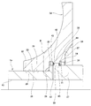
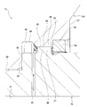
- FIG. 2 is an enlarged view of part A in FIG.
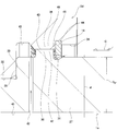
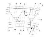
- FIG. 3 is an enlarged view of a portion B in FIG. 4 is a view taken in the direction of arrow C in FIG.
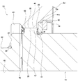
- FIG. 5 is a diagram corresponding to FIG. 3 and showing a second example of the embodiment of the present invention.
- FIG. 6 is a diagram corresponding to FIG. 3 and showing a third example of the embodiment of the present invention.
- FIG. 7 is a diagram corresponding to FIG. 3 and showing a fourth example of the embodiment of the present invention.
- FIG. 8 (A) is a view corresponding to FIG.
- FIG. 8 (B) is a view as viewed from arrow D in FIG. 8 (A) (A). is there.
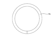
- FIG. 9 is a front view showing a lubricant damming member taken out and showing a sixth example of the embodiment of the present invention.
- FIG. 10 is a sectional view showing a conventional toroidal continuously variable transmission.
- the toroidal continuously variable transmission 13 of this example is applied, for example, as a transmission for an aircraft generator, and includes a rotating shaft 1a, a pair of outer disks 2c and 2d corresponding to input disks, and an output side.
- An inner disk 6a corresponding to the disk, a plurality of power rollers 7, a plurality of trunnions (not shown), a hydraulic pressing device (loading device) 10a, and a lubricating oil damming member 14 are provided.
- the rotating shaft 1a is supported on the upper side of the actuator case 15 through a pair of support columns 16 and an inner disk 6a so as to be rotatable only. Specifically, the rotating shaft 1a is formed on the inner diameter side of the inner disk 6a rotatably supported by a thrust angular ball bearing on a support ring provided in the middle part of the pair of support columns 16, respectively. It is rotatably supported by a radial needle bearing.
- the “axial direction” means the axial direction of the rotating shaft 1a (the left-right direction in FIGS. 1 to 3) unless otherwise specified.
- the right side of FIGS. 1 to 3 which is the distal end side of the rotating shaft 1a corresponds to one axial end side
- the left side of FIGS. 1 to 3 which is the proximal end side of the rotating shaft 1a corresponds to the other axial end side.
- Each of the outer disks 2c and 2d has axial side surfaces (inner side surfaces) each formed by a toroidal curved surface having an arc cross section, and is close to both axial ends of the rotating shaft 1a with the axial side surfaces facing each other.
- the portion is supported so as to be able to rotate in synchronization with the rotating shaft 1a and to move in the distance from each other.
- the outer disk 2c provided on the left side in FIG. 1 which is the other axial end side (base end side) of the rotating shaft 1a is used as a cylinder constituting the pressing device 10a.
- the rotary shaft 1a is supported by the rotary shaft 1a so that it can be slightly displaced in the axial direction and can be rotated in synchronization with the rotary shaft 1a.
- the cylinder 17 is configured by coupling and fixing the outer peripheral edge portion of the inner diameter side cylinder element 18 and the inner peripheral edge portion of the outer diameter side cylinder element 19.
- the male spline part formed in the part near the other axial end of the outer peripheral surface is spline engaged.
- a locking groove 20 is formed in the axially other end side portion than a portion where the inner diameter side cylinder element 18 is fitted, and a locking ring 21 is formed in the locking groove 20. Locked. Then, one end surface in the axial direction of the locking ring 21 is abutted against the other axial end surface of the inner diameter side portion of the inner diameter side cylinder element 18, and the cylinder 17 is displaced in the direction away from the outer disk 2c (left side in FIG. 1). To prevent you from doing. Therefore, the inner diameter side cylinder element 18 can be transferred to the other end portion in the axial direction of the rotating shaft 1a while being able to transmit torque and prevented from being displaced toward the other end side in the axial direction. It is fitted.
- the locking ring 21 is formed by combining a plurality of (for example, 2 to 4) partial arc-shaped elements in the circumferential direction and locking the plurality of elements in the locking groove 20. It is configured in an annular shape. Further, in order to prevent the plurality of elements constituting the locking ring 21 from coming out radially outward from the locking groove 20, the periphery of the plurality of elements is covered with a restraining ring 22. In the case of the illustrated structure, the restraining ring 22 is rotationally driven by a power source such as an engine, and the driving torque transmitted to the restraining ring 22 is transmitted to the rotating shaft 1a and the outer disk 2c via the cylinder 17. It is configured.
- a double piston type pressing device 10 a is configured in the cylinder 17.
- the toroidal continuously variable transmission 13 of this example introduces a predetermined hydraulic pressure into the hydraulic chambers 25a and 25b, so that the outer disk 2c on the other end side in the axial direction is changed to the outer disk 2d on one end side in the axial direction. In other words, it can be pressed with a force corresponding to the hydraulic pressure.
- the outer disk 2d provided on the right side in FIG. 1, which is one axial end side (tip side) of the rotating shaft 1a, is an axial direction that is a direction away from the outer disk 2c.
- the rotating shaft 1a supports the rotating shaft 1a so that it cannot be displaced toward one end and can rotate in synchronization with the rotating shaft 1a.
- a portion closer to one axial end of the rotating shaft 1a has a stepped surface on the axial side from the other end side in the axial direction to the one end side (from the left side to the right side in FIG. 1). 28 is formed in a stepped shape that is continuous.
- the outer peripheral surface of the small-diameter shaft portion 26 is formed by an inner cylindrical surface portion 29 whose cross-sectional shape with respect to a virtual plane orthogonal to the central axis of the rotation shaft 1a is a regular circular shape without distortion and whose outer diameter dimension does not change in the axial direction. It is configured. Further, a male spline portion 30 having an outer diameter dimension larger than that of the remaining portion of the large diameter shaft portion 27 is provided at an intermediate portion in the axial direction of the large diameter shaft portion 27. In the illustrated example, a clearance groove 31 that is recessed radially inward is provided over the entire circumference in a portion of the large-diameter shaft portion 27 that is adjacent to one end of the male spline portion 30 in the axial direction. Further, the shaft-side step surface 28 exists on a virtual plane orthogonal to the central axis of the rotating shaft 1a.
- a central hole 32 penetrating in the axial direction for inserting the rotating shaft 1a.
- the center hole 32 has a small-diameter hole portion 33 and a medium-diameter hole portion 34 that are continuous from the other end side in the axial direction to one end side (from the left side to the right side in FIGS. 1 to 3) by a disc-side step surface 35;
- the medium-diameter hole portion 34 and the large-diameter hole portion 36 are configured in a stepped shape in which the disk-side flat surface 37 is continued.
- a female spline portion 38 that can be spline-engaged with the male spline portion 30 is provided at an axially intermediate portion of the medium diameter hole portion 34.
- the inner peripheral surface of the small-diameter hole portion 33 is constituted by an outer cylindrical surface portion 39 having an inner diameter smaller than the diameter of the inscribed circle of the female spline portion 38.
- the outer cylindrical surface portion 39 is configured such that the cross-sectional shape with respect to a virtual plane orthogonal to the central axis of the outer disk 2d is a regular circle without distortion, and the outer diameter dimension does not change in the axial direction.
- the inner diameter of the outer cylindrical surface portion 39 in the free state is slightly smaller than the outer diameter of the inner cylindrical surface portion 29 in the free state.
- the disc-side step surface 35 and the disc-side flat surface 37 exist on a virtual plane orthogonal to the central axis of the outer disc 2d.
- the shaft-side step surface 28 formed on the outer peripheral surface of the rotating shaft 1a and the disk-side step surface 35 formed on the inner peripheral surface of the outer disk 2d are brought into contact in the axial direction.
- the male spline portion 30 and the female spline portion 38 are spline-engaged in a state where the axial direction of the outer disk 2d with respect to the rotation shaft 1a is achieved, and the inner cylindrical surface 29 and the outer cylindrical surface portion 39 are It is fitted with an interference fit by press fitting or inlay fitting.
- the outer disk 2d is supported so as to be able to rotate in synchronization with the rotating shaft 1a in a state in which displacement toward one end in the axial direction is prevented with respect to a portion near the one end of the rotating shaft 1a. Yes.
- a main lubricating oil passage 41 extending in the axial direction for supplying lubricating oil to the spline engaging portion 40 of the male spline portion 30 and the female spline portion 38 inside the rotating shaft 1a, and the main lubricating oil
- a sub-lubricating oil flow path 42 is provided that branches in a radial direction from a part of the axial direction of the flow path 41.
- the downstream end portion of the sub-lubricating oil passage 42 is axially other end side of the outer peripheral surface of the large-diameter shaft portion 27 of the rotary shaft 1a (see FIGS. 1 to 3) from the portion where the male spline portion 30 is provided. There is an opening in the part left (left side).
- the lubricating oil fed into the main lubricating oil passage 41 of the rotating shaft 1a passes through the auxiliary lubricating oil passage 42 and the outer peripheral surface of the rotating shaft 1a and the outer disk 2d as shown by arrows in FIG.
- the spline engaging portion 40 is fed into an annular oil retaining space 43 provided adjacent to the other axial end side of the spline engaging portion 40 in the portion between the inner peripheral surface of the spline engaging portion.
- the lubricating oil that has passed through the annular oil retaining space 43 passes through the spline engaging portion 40 from the other end side in the axial direction toward one end side (from the left side to the right side in FIGS. 1 to 3). Lubricate.
- the lubricating oil supplied to the annular oil retaining space 43 is prevented from leaking to the other end in the axial direction by the press-fitting fitting portion between the inner cylindrical surface 29 and the outer cylindrical surface portion 39. Therefore, the spline engaging portion 40 is efficiently supplied.
- the lubricating oil damming member 14 is supported and fixed on the inner peripheral surface of the outer disk 2d.
- the lubricating oil damming member 14 is made of an elastic material and has an annular plate shape as a whole.
- the lubricating oil damming member 14 is supported and fixed to a portion of the center hole 32 of the outer disk 2d adjacent to one end side in the axial direction of the female spline portion 38. ing.
- the outer diameter side portion of the lubricating oil damming member 14 is provided in a portion adjacent to one axial end side of the female spline portion 38 in the middle diameter hole portion 34 constituting the center hole 32.
- the locking groove 44 is locked. That is, the lubricating oil blocking member 14 is supported by a portion adjacent to the downstream side with respect to the spline engagement portion 40 in the flow direction of the lubricating oil. In this state, the other axial side surface of the lubricating oil damming member 14 is in contact with one axial end surface of the female spline portion 38.
- one end surface in the axial direction of the male spline portion 30 constituting the spline engaging portion 40 is in a state where the axial side step surface 28 and the disc side step surface 35 are in contact with each other in the axial direction. Since the female spline portion 38 is positioned on the other end side in the axial direction with respect to the one axial end surface, the gap between the other axial side surface of the lubricating oil blocking member 14 and the one axial end surface of the male spline portion 30 is between A slight gap 45 in the axial direction is formed over the entire circumference.
- the outer diameter D of the lubricating oil blocking member 14 is sufficiently larger than the root circle diameter df 46 of the female spline teeth 46 of the female spline portion 38,
- the inner diameter dimension d of the lubricating oil blocking member 14 is smaller than the root diameter df 47 of the male spline teeth 47 of the male spline portion 30.
- the outer peripheral edge portion O of the lubricating oil damming member 14 is located radially outside the root circle of the female spline teeth 46, and the inner peripheral edge portion I of the lubricating oil damming member 14 is the male spline.
- the tooth 47 is located radially inward from the root circle.
- the lubricating oil blocking member 14 is formed between the tooth bottom surface of the female spline teeth 46 and the tooth tip surface of the male spline teeth 47, and has a substantially rectangular cross section (or a substantially triangular cross section).
- the oil channel 48 is located at a portion adjacent to one axial end of the opening on the one axial end (exit side). For this reason, the entire range from the radially outer side to the inner side of the opening in the axial direction at one end side (exit side) of each outer diameter side lubricating oil channel 48 is axially determined by the outer diameter side portion of the lubricating oil damming member 14. It is in a state of being blocked (dammed).
- each outer diameter side lubrication is performed.
- the lubricating oil that passes through the oil flow path 48 is not completely prevented from being discharged from the opening on the one axial end side (exit side), and can be discharged little by little through the gap 45.
- the lubricating oil damming member 14 is formed between the tooth tip surface of the female spline teeth 46 and the tooth bottom surface of the male spline teeth 47, and has a substantially inverted triangular cross section (or a substantially rectangular cross section). (Shape) of the inner diameter side lubricating oil passage 49 is located at a portion adjacent to one axial end of the opening (exit side) opening in the axial direction. For this reason, the entire range from the radially outer side to the inner side of the opening in the axial direction at one end side (outlet side) of each of the inner diameter side lubricating oil passages 49 is closed in the axial direction by the inner diameter side portion of the lubricating oil damming member 14.
- each inner diameter side lubricating oil Lubricating oil passing through the flow path 49 is not completely prevented from being discharged from the opening on the one end side (outlet side) in the axial direction, and can be discharged little by little through the gap 45.
- the male spline portion 30 of the large-diameter shaft portion 27 of the rotating shaft 1a is not limited to the case where the inner diameter dimension d of the lubricating oil damming member 14 is in either the free state or the assembled state. It is set to be larger than the outer diameter D 27 of the portion on the one end side in the axial direction (the tip side, the right side in FIGS. 1 to 3) from the provided portion. Therefore, a gap is formed between the inner peripheral surface of the lubricating oil damming member 14 and the outer peripheral surface of the relief groove 31 of the rotating shaft 1a in the assembled state so as to allow the lubricating oil to pass to one end side in the axial direction. Is done.
- the outer diameter dimension D of the lubricating oil damming member 14 is the inner diameter dimension d 34 of the medium diameter hole portion 34 (the portion removed from the portion where the locking groove 44 is provided) in the center hole 32 of the outer disk 2d. Larger than the inner diameter dimension of the large-diameter hole 36.
- the axial direction of the rotary shaft 1a in the order of the outer disk 2d, the inner disk 6a, the outer disk 2c, and the pressing device 10a is inserted from the other end side (base end side) and assembled to the rotating shaft 1a.
- the outer disk 2d is centered by the fitting portion between the inner cylindrical surface 29 and the outer cylindrical surface part 39 when the outer disk 2d is attached to a portion near one axial end of the rotating shaft 1a. Therefore, the female spline portion 38 can be easily splined with the male spline portion 30.
- the lubricating oil damming member 14 is assembled from one end side (tip side) in the axial direction of the rotating shaft 1a. Specifically, the lubricating oil damming member 14 is moved from one axial end side of the rotating shaft 1a to the other end side, and the outer diameter side portion of the lubricating oil damming member 14 is moved to the center hole 32 of the outer disk 2d. It locks in the provided locking groove 44. In order to pass the inside of the center hole portion 34 in the center hole 32, for example, the lubricating oil damming member 14 is twisted so that the outer diameter side portion is positioned closer to the one end side in the axial direction than the inner diameter side portion.
- the outer diameter is made smaller than the inner diameter of the medium-diameter hole 34, or the outer diameter of the lubricating oil damming member 14 is elastically reduced to reduce the outer diameter.
- the inner diameter dimension of the medium diameter hole 34 is made smaller.
- the spline engaging portion 40 between the rotating shaft 1a and the outer disk 2d can be efficiently lubricated with lubricating oil.
- the entire annular disk 2d is adjacent to the downstream side with respect to the female spline portion 38 with respect to the flow direction of the lubricating oil, and the lubricating oil damming member 14 having an annular shape as a whole. Is supported. Inner diameter d of the lubricant blocking member 14, the tooth bottom circle diameter df 46 and the addendum circle diameter da 46 of the internal spline 46, and, is smaller than the tooth gap bottom circle diameter df 47 of the male spline teeth 47 (D ⁇ df 47 ⁇ da 46 ⁇ df 46 ).
- each outer diameter side lubricating oil channel 48 and each inner diameter side lubricating oil channel 49 is blocked in the axial direction. It is. Therefore, the lubricating oil supplied through the main lubricating oil passage 41, the auxiliary lubricating oil passage 42, and the annular oil retaining space 43 provided in the rotary shaft 1a moves radially outward by the action of centrifugal force. In this case, it is possible to prevent the lubricating oil from intensively passing through the outer diameter side lubricating oil channel 48 and being discharged, and to reduce the amount of lubricating oil passing through the outer diameter side lubricating oil channel 48.
- the lubricating oil damming member 14 is supported by a portion of the outer disk 2d on one end side in the axial direction adjacent to one end side in the axial direction of the female spline portion 38,
- the inner diameter dimension of the lubricating oil damming member 14 is configured to be larger than the outer diameter dimension of the portion of the rotating shaft 1a that is on the one end side in the axial direction than the portion where the male spline portion 30 is formed. ing. Therefore, the lubricating oil damming member 14 can be easily assembled from the one end side (tip side) in the axial direction of the rotating shaft 1a. For this reason, it is possible to suppress a decrease in the assemblability of the toroidal continuously variable transmission 13 due to the addition of the lubricating oil damming member 14.
- the locking groove 44 in the first example of the embodiment is formed in a portion adjacent to one end side in the axial direction of the female spline portion 38 in the medium diameter hole portion 34 constituting the center hole 32 of the outer disk 2d.
- a locking groove 44a for locking the retaining ring 50 is provided in the intermediate portion in the axial direction of the medium diameter hole 34 without providing (see FIGS. 1 to 3).
- the lubricating oil damming member 14 a is made of an elastic material or metal, and the outer diameter of the lubricating oil damming member 14 a is larger than that of the female spline portion 38 in the medium diameter hole portion 34. It is set slightly smaller than the inner diameter dimension of the one end portion in the direction.
- the retaining ring 50 is, for example, in the shape of a ring shape (C shape) and can be reduced in diameter relatively easily.
- a third example of the embodiment of the present invention will be described with reference to FIG.
- the feature of this example is also in the method of fixing the lubricating oil damming member 14b to the outer disk 2d.
- the lubricating oil damming member 14 b is supported and fixed to the outer disk 2 d using the fixing screw 51.
- a female spline portion 38a is formed at one axial end portion of the medium-diameter hole portion 34 constituting the center hole 32 of the outer disk 2d.
- the lubricating oil damming member 14 b is supported and fixed to the disk-side flat surface 37 constituting the center hole 32 by a plurality of fixing screws 51.
- the other axial end portion (tip portion) of the fixing screw 51 inserted through the portion near the outer diameter of the lubricating oil blocking member 14 b in the axial direction is screwed to the disk-side flat surface 37.
- the lubricating oil damming member 14b is made of metal, and the outer diameter of the lubricating oil damming member 14b is the inner diameter of the other end portion in the axial direction of the female spline portion 38a in the medium diameter hole 34. It is set sufficiently larger than.
- the lubricating oil damming member 14b can be easily supported and fixed from one axial end side of the outer disk 2d by using a tool (for example, a driver) (not shown), so that the toroidal continuously variable transmission 13 Assembly work efficiency can be further improved. Furthermore, since the lubricating oil damming member 14b is easily visible from the outside after the assembly is completed, it is possible to prevent the assembly of the lubricating oil damming member 14b. About another structure and an effect, it is the same as that of the 1st example of embodiment.
- a fourth example of the embodiment of the present invention will be described with reference to FIG.
- the feature of this example also resides in the method of fixing the lubricating oil damming member 14c to the outer disk 2d. That is, in this example, the lubricating oil damming member 14c is directly supported and fixed to the outer disk 2d by press-fitting.
- a locking groove 44 (see FIGS. 1 to 3) is formed in a portion adjacent to one end in the axial direction of the female spline portion 38 in the medium diameter hole portion 34 constituting the center hole 32 of the outer disk 2d. ) Is not provided. That is, a portion of the medium diameter hole portion 34 that is closer to one end side in the axial direction than the portion where the female spline portion 38 is provided is constituted by the fitting cylindrical surface 52 whose inner diameter dimension does not change in the axial direction.
- the lubricant damming member 14 c is made of an elastic material or metal, and the outer diameter of the lubricant damming member 14 c is slightly smaller than the inner diameter of the fitting cylindrical surface 52. It is set large.
- the lubricating oil damming member 14c is elastically deformed and pushed into the fitting cylindrical surface portion 52 from one end side in the axial direction of the outer disk 2d.
- the member 14c can be easily supported and fixed to the outer disk 2d. That is, also in this example, the assembly work efficiency of the toroidal continuously variable transmission 13 can be further improved. Also in this example, the lubricating oil damming member 14c can be easily visually recognized from the outside after the assembly is completed, so that it is possible to prevent forgetting to attach the lubricating oil damming member 14c.
- a fifth example of the embodiment of the present invention will be described with reference to FIG.
- the feature of this example is that the lubricating oil blocking member 14d is supported not on the outer disk 2e but on the rotating shaft 1b. That is, in the case of this example, the lubricating oil damming member 14d is fitted into a portion of the outer peripheral surface of the rotating shaft 1b adjacent to one end side in the axial direction of the portion provided with the male spline portion 30 by an interference fit. It is fixed (press-fit). Further, a minute gap is provided between the outer peripheral surface of the lubricating oil damming member 14d and the medium diameter hole 34 of the outer disk 2e. For this reason, the lubricating oil damming member 14 d is a clearance fit with respect to the medium diameter hole 34.
- the lubricating oil damming member 14d is made of an elastic material or metal, and a plurality of oil passage grooves that are recessed radially outward on the inner peripheral surface of the lubricating oil damming member. 52 are provided at equal intervals in the circumferential direction. These oil passage grooves 52 are provided over the entire length in the axial direction on the inner peripheral surface of the lubricating oil blocking member 14d. Further, in the case of this example, the cross-sectional shape of each oil passage groove 52, 52 is substantially semicircular, and the diameter of the circumscribed circle passing through the bottom of these oil passage grooves 52 is the outer disk 2e. It is set smaller than the diameter of the tip circle of the female spline teeth 46 of the female spline portion 38 provided. The lubricating oil blocking member 14d can be easily assembled from one axial end of the rotating shaft 1b.
- the lubricating oil blocking member 14d is formed between the tooth bottom surface of the female spline teeth 46 and the tooth tip surface of the male spline teeth 47 constituting the male spline portion 30.
- the entire opening on one end side (outlet side) in the axial direction of the outer diameter side lubricating oil passage 48 (see FIG. 4) having a substantially triangular shape (or a cross section) can be closed in the axial direction.
- the lubricating oil damming member 14d is used to lubricate the inner diameter side of a substantially inverted triangular section (or a substantially rectangular section) formed between the tip surface of the female spline teeth 46 and the bottom surface of the male spline teeth 47.
- a portion that does not overlap with the oil passage groove 52 in the axial direction can be blocked in the axial direction.
- the lubricating oil supplied through the inside of the rotary shaft 1b moves radially outward due to the action of centrifugal force, the lubricating oil is prevented from intensively passing through the outer diameter side lubricating oil passage 48. As a result, the amount of lubricating oil passing through the outer diameter side lubricating oil passage 48 can be reduced. Further, since the lubricating oil can intensively pass through the inner diameter side lubricating oil flow path 49, the lubricating oil is effectively fed into the portion between the tooth surfaces of the female spline teeth 46 and the male spline teeth 47. Therefore, the spline engaging portion 40 can be efficiently lubricated.
- the lubricating oil discharged into the gap 45 between the other axial end surface of the lubricating oil blocking member 14d and the one axial end surface of the male spline portion 30 passes through the oil passage groove 52 to the shaft. It is discharged to one end side in the direction.
- the portion between the other axial end surface of the lubricating oil blocking member 14d and the one axial end surface of the female spline portion 38 that is, the portion surrounded by the broken line in FIG.
- the lubricating oil sandwiched between O-rings and the like and discharged into the gap 45 flows between the outer peripheral surface of the lubricating oil damming member 14d and the inner peripheral surface of the medium diameter hole 34 of the outer disk 2e. It can also be prevented.
- a sealing groove (notch) opened in the axial direction is provided on one of the other axial end surface of the lubricating oil blocking member 14d and one axial end surface of the female spline portion 38.
- the sealing member can also be supported.
- the lubricating oil damming member 14e is a metal ring material made of a metal wire having a circular cross section or a rectangular cross section of at least one turn (1 turn in the illustrated example) as shown in FIG. It is in the point comprised by.
- the manufacturing cost of the lubricating oil damming member 14e can be reduced. Further, since the lubricating oil damming member 14e can be elastically deformed with a relatively small force, it is possible to improve the efficiency of attaching the lubricating oil damming member. About another structure and an effect, it is the same as that of the 1st example of embodiment.
- the support structure of the lubricating oil damming member for the outer disk and the rotating shaft is not limited to the structure of each example of the above-described embodiment, and various conventionally known support structures are used. It is also possible to adopt. Further, the shape of the lubricating oil blocking member is not limited to the shape of each example of the embodiment, and other shapes can be adopted as long as the function can be secured.
- the inner diameter dimension of the lubricating oil damming member is at least larger than the diameter of the tip of the female spline tooth of the female spline tooth formed on the inner peripheral surface of the outer disk on one end side in the axial direction. It is smaller or smaller than the diameter of the root circle of the male spline teeth of the male spline portion formed on the outer peripheral surface of the rotating shaft.
- the lubricating oil blocking member can prevent the entire outlet side opening of the outer diameter side lubricating oil passage, and at least the outer diameter side portion of the outlet side opening of the inner diameter side lubricating oil passage.
- the lubricating oil can be efficiently fed into the portion between the tooth surfaces of the female spline teeth and the male spline teeth, and the spline engaging portion can be effectively lubricated.
- the inner diameter dimension of the lubricating oil damming member is set to be smaller than at least the root diameter of the female spline teeth of the female spline part, at least the outlet side opening of the outer diameter side lubricating oil flow path It is possible to block the outer diameter side portion. Accordingly, it is possible to prevent the lubricating oil from intensively passing through the outer diameter side lubricating oil passage, and such an embodiment also belongs to the present invention.
- the present invention is not limited to the half-toroidal toroidal transmission as shown, but can also be applied to a full toroidal toroidal continuously variable transmission.
Landscapes
- Engineering & Computer Science (AREA)
- General Engineering & Computer Science (AREA)
- Mechanical Engineering (AREA)
- Friction Gearing (AREA)
- General Details Of Gearings (AREA)
Abstract
回転軸と外側ディスクとのスプライン係合部を、潤滑油により効率よく潤滑できる、トロイダル無段変速機の構造を実現する。外側ディスク2dのうち、中心孔32に形成した雌スプライン部38に対して潤滑油の流れ方向に関して下流側に隣接する部分に、全体が円環状で、回転軸1aの外周面に設けられた雄スプライン部30を構成する雄スプライン歯の歯底円直径よりも小さな内径寸法を有する、潤滑油堰き止め部材14が支持固定されている。
Description
本発明は、航空機用発電機を含む発電機、ポンプなどの各種産業機械、自動車を含む車両、建設機械などに組み込まれるトロイダル無段変速機に関する。
特開2003-214516号公報などに記載された構造のトロイダル無段変速機が、航空機用発電機や自動車などに用いられる変速装置としてすでに使用されている。また、特開2004-169719号公報などに記載されているような、トロイダル無段変速機と遊星歯車機構とを組み合わせて変速比の調整幅を広くしたパワースプリットシステムも、すでに知られている。
図10は、従来構造のトロイダル無段変速機の1例を示している。この従来構造は、回転軸1と、この回転軸1の軸方向両端寄り部分の周囲にそれぞれのボールスプライン3を介して支持された1対の外側ディスク2a、2bを備える。1対の外側ディスク2a、2bは、それぞれ断面円弧形のトロイド曲面からなる軸方向側面(内側面)を有し、かつ、これらの軸方向側面同士を互いに対向させた状態で配置されている。1対の外側ディスク2a、2bは、ボールスプライン3により、互いに遠近動可能に、かつ、回転軸1を介して互いに同期して回転することが可能である。また、回転軸1の軸方向中間部周囲には、回転軸1に対する相対回転を可能に、筒部材4が支持されている。この筒部材4の外周面の軸方向中央部には、歯車5を固設され、かつ、この筒部材4の外周面の軸方向両端部には、内側ディスク6が、筒部材4と同期した回転を可能に支持されている。内側ディスク6は、1対の素子により構成される。内側ディスク6を構成する1対の素子は、それぞれ断面円弧形のトロイド曲面からなる軸方向側面を有し、かつ、これらの1対の素子の軸方向側面を、1対の外側ディスク2a、2bの軸方向側面にそれぞれ対向させた状態で配置されている。
回転軸1の軸方向両端寄り部分に配置された1対の外側ディスク2a、2bと、回転軸1の軸方向中間部に配置された内側ディスク6との間部分のそれぞれには、複数のパワーローラ7が挟持されている。複数のパワーローラ7は、それぞれ部分球状凸面からなる周面を有する。複数のパワーローラ7は、それぞれに対応するトラニオン8によって、回転自在に支持されている。1対の外側ディスク2a、2bと内側ディスク6との間部分にそれぞれ挟持されている複数のパワーローラ7は、1対の外側ディスク2a、2bの回転に伴って回転しつつ、1対の外側ディスク2a、2bから内側ディスク6に動力を伝達する。あるいは、複数のパワーローラ7は、内側ディスク6の回転に伴って回転しつつ、内側ディスク6から1対の外側ディスク2a、2bに動力を伝達する。
より具体的には、トロイダル無段変速機の運転時には、回転軸1の一端側(先端側)に配置された外側ディスク2aと回転軸1の他端側(基端側)に配置された外側ディスク2bとのうち、基端側にある外側ディスク2bが、駆動軸9により機械式の押圧装置10を介して回転駆動する。この結果、回転軸1の軸方向両端寄り部分に支持された1対の外側ディスク2a、2bが、互いに近づく方向に押圧されつつ同期して回転する。そして、1対の外側ディスク2a、2bの回転が、両側にある複数のパワーローラ7を介して内側ディスク6に伝達され、歯車5から取り出される。あるいは、内側ディスク6に、歯車5および筒部材4を介して、駆動源からの動力を入力し、内側ディスク6の両側に配置された複数のパワーローラ7を介して1対の外側ディスク2a、2bに動力を伝達し、1対の外側ディスク2a、2bから動力を取り出すように構成することもできる。
回転軸1の軸方向両端部の近傍で、1対の外側ディスク2a、2bを軸方向両側から挟む位置に、それぞれ予圧ばね11a、11bが設けられている、予圧ばね11a、11bにより、押圧装置10の非作動時(駆動軸9の停止時)にも、1対のパワーローラ7の周面と、1対の外側ディスク2a、2bおよび内側ディスク6の側面との転がり接触部(トラクション部)の面圧が、必要最低限だけ確保されている。したがって、それぞれの転がり接触部は、トロイダル無段変速機の運転開始直後から、過大な滑りを生じることなく、動力伝達を開始することができる。
ところで、前記必要最低限の面圧を確保するための弾力は、回転軸1の軸方向基端側で、押圧装置10の内径側に配置された予圧ばね11bのみによっても得ることが可能である。回転軸1の軸方向先端部(一端部)に螺着したローディングナット12と外側ディスク2aの外側面との間に配置された予圧ばね11aは、押圧装置10の急な作動時に加わる衝撃を緩和するためのものであるため、省略することが可能である、そこで、部品点数の低減および組立作業効率の向上などを図る観点から、特開2015-090160号公報に記載されているように、回転軸1の先端側(一端側)の予圧ばね11aを省略し、かつ、外側ディスク2aを回転軸1に対して、ボールスプライン3を介することなく、スプライン係合によって相対回転不能に支持する構造が提案されている。また、ローディングナット12に代替して、回転軸1の先端部に外向フランジ状の鍔部を設けた構造や、コッタと呼ばれる係止環を回転軸1の先端部に係止した構造なども知られている。
いずれの構造の場合にも、回転軸の軸方向一端部(先端部)の外周面に設けた雄スプライン部と、この回転軸の軸方向一端側(先端側)に配置された外側ディスクの中心孔に設けた雌スプライン部とをスプライン係合させて、この外側ディスクを回転軸に対して同期した回転を可能に支持することになる。このような構造では、回転軸の雄スプライン部と外側ディスクの雌スプライン部とのスプライン係合部に、パワーローラによる押し付け力によって生じる、外側ディスクの弾性変形に起因した応力が集中しやすいだけでなく、スプライン係合部に存在する隙間に起因してフレッチング摩耗が生じやすいという問題が生じる。したがって、トロイダル無段変速機の長寿命化のためには、前記スプライン係合部を潤滑油により潤滑することが必要不可欠となる。
特開平5-295348号公報、特開平6-313471号公報、特開平7-332589号公報には、前記スプライン係合部における潤滑油による潤滑に関して、これらの潤滑油が外部に漏れることを防止するためにシール部材を設けることが開示されている。
従来構造のトロイダル無段変速機においては、スプライン係合部の潤滑に関して、スプライン係合部をより効果的に潤滑することについては、特段の考慮はなされていない。このため、スプライン係合部に供給された潤滑油の大部分は、遠心力の作用によりスプライン係合部の径方向外方に移動し、外側ディスクの雌スプライン部を構成する雌スプライン歯の歯底面と回転軸の雄スプライン部を構成する雄スプライン歯の歯先面との間に形成される外径側潤滑油流路を集中的に通過して排出されてしまうため、スプライン係合部全体を効果的に潤滑することが困難である。
本発明は、上述のような事情に鑑みて、回転軸と外側ディスクとのスプライン係合部全体を、潤滑油により効率よく潤滑できる、トロイダル無段変速機の構造を実現することを目的とする。
本発明のトロイダル無段変速機は、回転軸と、1対の外側ディスクと、内側ディスクと、複数のパワーローラとを備える。
前記回転軸は、外周面のうちの該回転軸の軸方向一端側(先端側)部分に、雄スプライン部を備えている。なお、「軸方向」とは、特に断らない限り、この回転軸の軸方向を意味する。
前記1対の外側ディスクは、それぞれ断面円弧形のトロイド曲面からなる軸方向側面(内側面)を有し、かつ、該軸方向側面同士を対向させた状態で、前記回転軸の軸方向両端寄り部分に、この回転軸と同期した回転を可能に、支持されている。該1対の外側ディスクのうち軸方向一端側(先端側)に配置された一方の外側ディスクの内周面には、前記雄スプライン部とスプライン係合する雌スプライン部が備えられている。
前記内側ディスクは、それぞれ断面円弧形のトロイド曲面からなる軸方向側面を軸方向両側に有し、該軸方向側面を前記1対の外側ディスクの軸方向側面に対向させた状態で、前記回転軸の軸方向中間部周囲に、この回転軸に対する相対回転を可能に支持されている。なお、内側ディスクは一体構造を採ることもできるが、それぞれが前記軸方向側面を有する1対の素子の組み合わせにより構成することもできる。
前記複数のパワーローラは、複数の支持部材(たとえば、トラニオン)によって、それぞれ回転自在に支持されている。該複数のパワーローラは、それぞれ部分球状凸面からなる周面を有し、該周面を、前記内側ディスクの軸方向側面と前記1対の外側ディスクの軸方向側面とに当接させている。
本発明のトロイダル無段変速機は、潤滑油堰き止め部材をさらに備える。該潤滑油堰き止め部材は、全体が円環状であり、前記一方の外側ディスクの前記雌スプライン部を構成する雌スプライン歯の歯底円直径よりも小さな内径寸法を有している。該潤滑油堰き止め部材は、前記一方の外側ディスクの内周面または前記回転軸の外周面における、前記雌スプライン部と前記雄スプライン部とのスプライン係合部を軸方向に通過して潤滑する潤滑油の流れ方向に関して、該スプライン係合部の下流側に隣接する部分に、前記一方の外側ディスクまたは前記回転軸と同軸に支持されている。
さらに、本発明のトロイダル無段変速機が、追加的に押圧装置を備える場合には、この押圧装置は、前記1対の外側ディスクのうちの軸方向他端側(回転軸の基端側)に備えられた他方の外側ディスクと、前記回転軸との間に設置され、この他方の外側ディスクを軸方向一端側(一方の外側ディスク)に向けて押圧可能に構成される。このような押圧装置としては、ローディングカムを組み込んだ機械式押圧装置、あるいは、油圧シリンダおよびピストンを備えた油圧式押圧装置が使用される。
本発明を実施する場合には、前記潤滑油堰き止め部材の内径寸法は、前記雌スプライン歯の歯先円直径よりも小さいことが好ましい。あるいは、前記潤滑油堰き止め部材の内径寸法は、前記雄スプライン部を構成する雄スプライン歯の歯底円直径よりも小さいことが好ましい。
前記潤滑油堰き止め部材は、前記一方の外側ディスクの内周面のうち、前記雌スプライン部の軸方向一端側に隣接する部分に支持されることが好ましい。さらに、前記潤滑油堰き止め部材の内径寸法は、前記回転軸のうち、前記雄スプライン部が形成された部分よりも軸方向一端側に存在する部分の外径寸法よりも大きいことが好ましい。
本発明のトロイダル型無段変速機では、回転軸と1対の外側ディスクのうちの軸方向一端側に備えられた一方の外側ディスクとのスプライン係合部全体を、潤滑油により効率よく潤滑することが可能となる。
すなわち、本発明のトロイダル無段変速機では、潤滑油堰き止め部材により、前記一方の外側ディスクの雌スプライン歯の歯底面と前記回転軸の雄スプライン歯の歯先面との間に形成される外径側潤滑油流路の出口側開口部のうち、少なくとも外径側部分を塞ぐ、ないしは、堰き止めることができる。
したがって、前記回転軸の内部に設けられた油路を通じて供給された潤滑油が、遠心力により径方向外方に移動した場合にも、前記外径側潤滑油流路を潤滑油が集中的に通過することを防止して、外径側潤滑油流路を通過する潤滑油量を減らすことが可能となる。
この結果、本発明のトロイダル無段変速機では、前記外径側潤滑油流路以外の部分にも潤滑油を効率よく通過させることができ、スプライン係合部全体をより効果的に潤滑することが可能になる。
[実施の形態の第1例]
図1~図4は、本発明の実施の形態の第1例を示している。本例のトロイダル無段変速機13は、たとえば航空機用発電機の変速装置として適用されるものであり、回転軸1aと、入力側ディスクに相当する1対の外側ディスク2c、2dと、出力側ディスクに相当する内側ディスク6aと、複数のパワーローラ7と、図示しない複数のトラニオンと、油圧式の押圧装置(ローディング装置)10aと、潤滑油堰き止め部材14とを備えている。
図1~図4は、本発明の実施の形態の第1例を示している。本例のトロイダル無段変速機13は、たとえば航空機用発電機の変速装置として適用されるものであり、回転軸1aと、入力側ディスクに相当する1対の外側ディスク2c、2dと、出力側ディスクに相当する内側ディスク6aと、複数のパワーローラ7と、図示しない複数のトラニオンと、油圧式の押圧装置(ローディング装置)10aと、潤滑油堰き止め部材14とを備えている。
回転軸1aは、アクチュエータケース15の上側に、1対の支柱16と内側ディスク6aとを介して回転のみ可能に支持されている。具体的には、回転軸1aは、1対の支柱16の中間部に設けた支持環部にそれぞれスラストアンギュラ型の玉軸受により回転自在に支持された内側ディスク6aの内径側に、1対のラジアルニードル軸受により回転自在に支持されている。
なお、本発明において、「軸方向」とは、特に断らない限り、回転軸1aの軸方向(図1~図3の左右方向)を意味する。また、回転軸1aの先端側である図1~図3の右側が軸方向一端側に、回転軸1aの基端側である図1~図3の左側が軸方向他端側に相当する。
外側ディスク2c、2dは、それぞれ断面円弧形のトロイド曲面からなる軸方向側面(内側面)を有し、かつ、この軸方向側面同士を対向させた状態で、回転軸1aの軸方向両端寄り部分に、この回転軸1aと同期した回転を可能に、かつ、互いに遠近動可能に支持されている。
具体的には、外側ディスク2c、2dのうち、回転軸1aの軸方向他端側(基端側)である、図1の左側に設けられた外側ディスク2cを、押圧装置10aを構成するシリンダ17を介して、軸方向の若干の変位を可能に、かつ、回転軸1aと同期した回転を可能に、この回転軸1aに支持している。シリンダ17は、内径側シリンダ素子18の外周縁部と、外径側シリンダ素子19の内周縁部とを結合固定することにより構成されており、このうちの内径側シリンダ素子18は、回転軸1cの外周面の軸方向他端寄り部分に形成した雄スプライン部に対し、スプライン係合させている。
また、回転軸1aのうちで、内径側シリンダ素子18を外嵌した部分よりも軸方向他端側部分に係止凹溝20を形成し、この係止凹溝20内に係止環21を係止している。そして、この係止環21の軸方向一端面を、内径側シリンダ素子18の内径側部分の軸方向他端面に突き当てて、シリンダ17が外側ディスク2cから離れる方向(図1の左側)に変位することを阻止している。したがって、内径側シリンダ素子18は、回転軸1aの軸方向他端寄り部分に対し、トルク伝達を可能に、かつ、軸方向他端側への変位を阻止された状態で、がたつきなく外嵌されている。
なお、係止環21は、複数(たとえば2個~4個)の部分円弧状の素子を円周方向に組み合わせて、これらの複数の素子を係止凹溝20に係止することにより、円環状に構成されている。また、係止環21を構成するこれらの複数の素子が、係止凹溝20から径方向外方に抜け出ることを防止するため、これら複数の素子の周囲を、抑え環22により覆っている。図示の構造の場合には、エンジンなどの動力源により抑え環22を回転駆動し、この抑え環22に伝わった駆動トルクを、シリンダ17を介して、回転軸1aおよび外側ディスク2cに伝達するように構成されている。
さらに、シリンダ17内には、2枚のピストン板23a、23bが組み付けられている。すなわち、軸方向他端側のピストン板23aとシリンダ17の底板部24との間部分、および、軸方向一端側のピストン板23bと外側ディスク2cとの間部分を、それぞれ油圧室25a、25bとすることにより、シリンダ17内に、ダブルピストン型の押圧装置10aが構成されている。本例のトロイダル無段変速機13は、これらの油圧室25a、25b内に所定圧の油圧を導入することで、軸方向他端側の外側ディスク2cを、軸方向一端側の外側ディスク2dに向け、前記油圧の大きさに応じた力で押圧可能に構成されている。
これに対し、外側ディスク2c、2dのうち、回転軸1aの軸方向一端側(先端側)である、図1の右側に設けられた外側ディスク2dは、外側ディスク2cから離れる方向である軸方向一端側への変位を不能に、かつ、回転軸1aと同期した回転を可能に、この回転軸1aに支持されている。具体的には、回転軸1aの軸方向一端寄り部分は、軸方向他端側から一端側(図1の左側から右側)に、小径軸部26と大径軸部27とを軸側段差面28により連続させた段付状に構成されている。小径軸部26の外周面は、回転軸1aの中心軸に直交する仮想平面に関する断面形状が、歪みのない正円形からなり、かつ、軸方向に関して外径寸法が変化しない、内側円筒面部29によって構成されている。また、大径軸部27の軸方向中間部には、この大径軸部27のうちの残部よりも外径寸法が大きくなった雄スプライン部30が備えられている。図示の例では、大径軸部27のうちで、雄スプライン部30の軸方向一端側に隣接する部分に、径方向内方に凹んだ逃げ凹溝31が全周にわたって備えられている。また、軸側段差面28は、回転軸1aの中心軸に対して直交する仮想平面上に存在している。
外側ディスク2dの中心には、回転軸1aを挿通するための、軸方向に貫通した中心孔32が備えられている。この中心孔32は、軸方向他端側から一端側(図1~図3の左側から右側)に、小径孔部33と中径孔部34とをディスク側段差面35により連続させ、かつ、中径孔部34と大径孔部36とをディスク側平坦面37により連続させた段付状に構成されている。中径孔部34の軸方向中間部に、雄スプライン部30とスプライン係合可能な雌スプライン部38が備えられている。
小径孔部33の内周面は、雌スプライン部38の内接円の直径よりも小さな内径寸法を有する外側円筒面部39により構成されている。この外側円筒面部39は、外側ディスク2dの中心軸に直交する仮想平面に関する断面形状が、歪みのない正円形からなり、かつ、軸方向に関して外径寸法が変化しないように構成されている。また、外側円筒面部39の自由状態での内径は、内側円筒面部29の自由状態での外径よりも、わずかに小さい。さらに、ディスク側段差面35およびディスク側平坦面37は、外側ディスク2dの中心軸に対して直交する仮想平面上に存在している。
トロイダル無段変速機13の組み立て状態では、回転軸1aの外周面に形成した軸側段差面28と外側ディスク2dの内周面に形成したディスク側段差面35とを軸方向に当接させることにより、回転軸1aに対する外側ディスク2dの軸方向に関する位置決めを図った状態で、雄スプライン部30と雌スプライン部38とがスプライン係合し、かつ、内側円筒面29と外側円筒面部39とを、圧入あるいはインロー嵌合により締り嵌めで嵌合させている。このような構成により、外側ディスク2dは、回転軸1aの軸方向一端寄り部分に対し、軸方向一端側への変位が阻止された状態で、回転軸1aと同期した回転を可能に支持されている。
回転軸1aの内部に、雄スプライン部30と雌スプライン部38とのスプライン係合部40に対し潤滑油を供給するための、軸方向に伸長した主潤滑油流路41と、この主潤滑油流路41の軸方向一部から径方向に分岐する、副潤滑油流路42が、設けられている。副潤滑油流路42の下流側端部は、回転軸1aの大径軸部27の外周面のうち、雄スプライン部30が備えられた部分から軸方向他端側(図1~図3の左側)に外れた部分に開口している。本例の場合、回転軸1aの主潤滑油流路41に送り込まれた潤滑油は、図3に矢印で示すように、副潤滑油流路42を通じて、回転軸1aの外周面と外側ディスク2dの内周面との間部分のうち、スプライン係合部40の軸方向他端側に隣接して設けられた環状保油空間43に送り込まれる。この環状保油空間43を通過した潤滑油は、スプライン係合部40を軸方向他端側から一端側(図1~図3の左側から右側)に向けて通過して、スプライン係合部40を潤滑する。なお、本例の場合、環状保油空間43に供給された潤滑油は、内側円筒面29と外側円筒面部39との圧入嵌合部により、軸方向他端側への油漏れが防止されているため、スプライン係合部40に効率よく供給される。
特に、本例の場合、スプライン係合部40をさらに効率よく潤滑するために、外側ディスク2dの内周面に、潤滑油堰き止め部材14が支持固定されている。この潤滑油堰き止め部材14は、弾性材製で、全体が円輪板状であり、外側ディスク2dの中心孔32のうち、雌スプライン部38の軸方向一端側に隣接する部分に支持固定されている。より具体的には、潤滑油堰き止め部材14の外径側部分が、中心孔32を構成する中径孔部34のうち、雌スプライン部38の軸方向一端側に隣接した部分に備えられた係止溝44に対して、係止されている。すなわち、潤滑油堰き止め部材14は、スプライン係合部40に対して、潤滑油の流れ方向に関して下流側に隣接する部分に支持されている。この状態で、潤滑油堰き止め部材14の軸方向他側面は、雌スプライン部38の軸方向一端面に当接している。ただし、本例の場合には、軸側段差面28とディスク側段差面35とを軸方向に当接させた状態で、スプライン係合部40を構成する雄スプライン部30の軸方向一端面を、雌スプライン部38の軸方向一端面よりも軸方向他端側に位置させているため、潤滑油堰き止め部材14の軸方向他側面と雄スプライン部30の軸方向一端面との間には、軸方向に関するわずかな隙間45が全周にわたって形成されている。
図4に示したように、本例の場合には、潤滑油堰き止め部材14の外径寸法Dは、雌スプライン部38の雌スプライン歯46の歯底円直径df46よりも十分に大きく、潤滑油堰き止め部材14の内径寸法dは、雄スプライン部30の雄スプライン歯47の歯底円直径df47よりも小さい。このため、潤滑油堰き止め部材14の外周縁部Oは、雌スプライン歯46の歯底円よりも径方向外側に位置しており、潤滑油堰き止め部材14の内周縁部Iは、雄スプライン歯47の歯底円よりも径方向内側に位置している。
したがって、潤滑油堰き止め部材14は、雌スプライン歯46の歯底面と雄スプライン歯47の歯先面との間に形成される、断面略矩形状(あるいは断面略三角形状)の外径側潤滑油流路48の軸方向一端側(出口側)開口部の軸方向一端側に隣接した部分に位置している。このため、それぞれの外径側潤滑油流路48の軸方向一端側(出口側)開口部の、径方向外側から内側にわたる全範囲が、潤滑油堰き止め部材14の外径側部分により軸方向に塞がれた(堰き止められた)状態となる。ただし、本例の場合には、潤滑油堰き止め部材14の軸方向他側面と雄スプライン部30の軸方向一端面との間に、隙間45が形成されているため、それぞれの外径側潤滑油流路48を通過する潤滑油は、軸方向一端側(出口側)開口部からの排出が完全に阻止されるわけではなく、隙間45を通じて少しずつ排出することが可能である。
本例の場合、同様に、潤滑油堰き止め部材14は、雌スプライン歯46の歯先面と雄スプライン歯47の歯底面との間に形成される、断面略逆三角形状(あるいは断面略矩形状)の内径側潤滑油流路49の軸方向一端側(出口側)開口部の軸方向一端側に隣接した部分に位置している。このため、それぞれの内径側潤滑油流路49の軸方向一端側(出口側)開口部の、径方向外側から内側にわたる全範囲が、潤滑油堰き止め部材14の内径側部分により軸方向に塞がれた(堰き止められた)状態となる。ただし、本例の場合には、潤滑油堰き止め部材14の軸方向他側面と雄スプライン部30の軸方向一端面との間に、隙間45が形成されているため、それぞれの内径側潤滑油流路49を通過する潤滑油は、軸方向一端側(出口側)開口部からの排出が完全に阻止されるわけではなく、隙間45を通じて少しずつ排出することが可能である。
さらに、本例の場合には、潤滑油堰き止め部材14の内径寸法dが、自由状態および組み付け状態のいずれの場合においても、回転軸1aの大径軸部27のうち、雄スプライン部30を設けた部分よりも軸方向一端側(先端側、図1~図3の右側)にある部分の外径寸法D27よりも大きく設定されている。したがって、組み付け状態で、潤滑油堰き止め部材14の内周面と回転軸1aの逃げ凹溝31の外周面との間には、潤滑油を軸方向一端側へと通過させるための隙間が形成される。また、潤滑油堰き止め部材14の外径寸法Dは、外側ディスク2dの中心孔32のうち、中径孔部34(係止溝44が設けられた部分から外れた部分)の内径寸法d34よりも大きく、大径孔部36の内径寸法よりも小さく設定されている。
以上のような構成を有する本例のトロイダル側無段変速機13を組み立てる場合には、外側ディスク2d、内側ディスク6a、外側ディスク2c、および、押圧装置10aの順で、回転軸1aの軸方向他端側(基端側)から挿入して、回転軸1aに対して組み付ける。なお、本例の場合、外側ディスク2dを、回転軸1aの軸方向一端寄り部分に取り付ける際に、内側円筒面29と外側円筒面部39との嵌合部により、外側ディスク2dの芯出しを行うことができるため、雌スプライン部38を雄スプライン部30に対して容易にスプライン係合させることが可能となっている。
本例の場合には、潤滑油堰き止め部材14を、回転軸1aの軸方向一端側(先端側)から組み付ける。具体的には、潤滑油堰き止め部材14を、回転軸1aの軸方向一端側から他端側に移動させて、潤滑油堰き止め部材14の外径側部分を外側ディスク2dの中心孔32に設けられた係止溝44に係止する。なお、中心孔32のうち、中径孔部34の内側を通過させるには、たとえば、潤滑油堰き止め部材14を捻って、その外径側部分が内径側部分よりも軸方向一端側に位置するように傾斜させることにより、その外径寸法を中径孔部34の内径寸法よりも小さくする、あるいは、潤滑油堰き止め部材14全体を弾性的に縮径することにより、その外径寸法を中径孔部34の内径寸法よりも小さくする。
以上のような構成を有する本例のトロイダル無段変速機13では、回転軸1aと外側ディスク2dとのスプライン係合部40を、潤滑油により効率よく潤滑することが可能である。
すなわち、本例のトロイダル無段変速機13では、外側ディスク2dのうち、雌スプライン部38に対し潤滑油の流れ方向に関して下流側に隣接する部分に、全体が円環状の潤滑油堰き止め部材14が支持されている。この潤滑油堰き止め部材14の内径寸法dは、雌スプライン歯46の歯底円直径df46および歯先円直径da46、並びに、雄スプライン歯47の歯底円直径df47よりも小さくなっている(d<df47<da46<df46)。このような潤滑油堰き止め部材14により、それぞれの外径側潤滑油流路48およびそれぞれの内径側潤滑油流路49の軸方向一端側(出口側)開口部全体が、軸方向に塞がれている。したがって、回転軸1aの内部に設けられた主潤滑油流路41、副潤滑油流路42、および、環状保油空間43を通じて供給された潤滑油が、遠心力の作用により径方向外側に移動した場合にも、潤滑油が外径側潤滑油流路48を集中的に通過して排出されてしまうことが防止され、外径側潤滑油流路48を通過する潤滑油量を減らすことが可能となる。また、本例の場合には、内径側潤滑油流路49、49を潤滑油が集中的に通過することも可能となるため、雌スプライン歯46と雄スプライン歯47との歯面同士の間部分に潤滑油を効果的に送り込んで、スプライン係合部40を効果的に潤滑することが可能となる。
さらに、本例のトロイダル型無段変速機13では、潤滑油堰き止め部材14が、軸方向一端側の外側ディスク2dのうち、雌スプライン部38の軸方向一端側に隣接する部分に支持され、かつ、潤滑油堰き止め部材14の内径寸法が、回転軸1aのうち、雄スプライン部30が形成された部分よりも軸方向一端側に存在する部分の外径寸法よりも大きくなるように構成されている。したがって、潤滑油堰き止め部材14を、回転軸1aの軸方向一端側(先端側)から容易に組み付けることが可能である。このため、潤滑油堰き止め部材14の追加に起因する、トロイダル無段変速機13の組立性の低下を抑制することができる。
[実施の形態の第2例]
本発明の実施の形態の第2例について、図5を参照しつつ説明する。本例の特徴は、入力側ディスク2dに対する潤滑油堰き止め部材14aの固定方法にある。すなわち、本例の場合には、潤滑油堰き止め部材14aは、外側ディスク2dに対して、止め輪50を利用して、支持固定されている。
本発明の実施の形態の第2例について、図5を参照しつつ説明する。本例の特徴は、入力側ディスク2dに対する潤滑油堰き止め部材14aの固定方法にある。すなわち、本例の場合には、潤滑油堰き止め部材14aは、外側ディスク2dに対して、止め輪50を利用して、支持固定されている。
具体的には、外側ディスク2dの中心孔32を構成する中径孔部34のうち、雌スプライン部38の軸方向一端側に隣接する部分に、実施の形態の第1例における係止溝44(図1~図3参照)を設けずに、中径孔部34の軸方向中間部に、止め輪50を係止するための係止溝44aが備えられている。また、本例の場合、潤滑油堰き止め部材14aは、弾性材製あるいは金属製であり、潤滑油堰き止め部材14aの外径寸法は、中径孔部34のうち雌スプライン部38よりも軸方向一端側部分の内径寸法よりもわずかに小さく設定されている。これに対し、止め輪50は、たとえば欠円環状(C字形状)で、比較的に容易に縮径可能に構成されている。
本例の場合、潤滑油堰き止め部材14aを、中径孔部34の内側を通過させる場合にも、潤滑油堰き止め部材14aを傾斜させたり、弾性変形させたりする必要がない。また、止め輪50を係止溝44aに係止する際に、止め輪50を、中径孔部34の内側を通過させる必要はあるが、止め輪50の内径寸法を小さくする必要性はない。したがって、止め輪50を、中径孔部34を通過させて係止溝44aに係止する作業は容易に行うことが可能である。このように、本例の場合には、トロイダル無段変速機13の組立作業効率をより向上させることができる。その他の構成および作用効果については、実施の形態の第1例と同様である。
[実施の形態の第3例]
本発明の実施の形態の第3例について、図6を参照しつつ説明する。本例の特徴も、外側ディスク2dに対する潤滑油堰き止め部材14bの固定方法にある。本例の場合、潤滑油堰き止め部材14bは、固定用ねじ51を利用して、外側ディスク2dに対して支持固定されている。
本発明の実施の形態の第3例について、図6を参照しつつ説明する。本例の特徴も、外側ディスク2dに対する潤滑油堰き止め部材14bの固定方法にある。本例の場合、潤滑油堰き止め部材14bは、固定用ねじ51を利用して、外側ディスク2dに対して支持固定されている。
本例の場合、外側ディスク2dの中心孔32を構成する中径孔部34の軸方向一端部に、雌スプライン部38aが形成されている。潤滑油堰き止め部材14bは、中心孔32を構成するディスク側平坦面37に対して、複数本の固定用ねじ51によって支持固定されている。具体的には、潤滑油堰き止め部材14bの外径寄り部分を軸方向に挿通した、固定用ねじ51の軸方向他端部(先端部)が、ディスク側平坦面37に対し螺着されている。また、潤滑油堰き止め部材14bは、金属製であり、潤滑油堰き止め部材14bの外径寸法は、中径孔部34のうちの雌スプライン部38aよりも軸方向他端側部分の内径寸法よりも十分に大きく設定されている。
本例の場合、図示しない工具(たとえば、ドライバ)を用いて、外側ディスク2dの軸方向一端側から潤滑油堰き止め部材14bを容易に支持固定することができるため、トロイダル無段変速機13の組立作業効率をより向上させることができる。さらに、組立完了後の状態で、潤滑油堰き止め部材14bを外部から視認しやすいため、潤滑油堰き止め部材14bの組み付け忘れを防止することもできる。その他の構成および作用効果については、実施の形態の第1例と同様である。
[実施の形態の第4例]
本発明の実施の形態の第4例について、図7を参照しつつ説明する。本例の特徴も、外側ディスク2dに対する潤滑油堰き止め部材14cの固定方法にある。すなわち、本例の場合には、潤滑油堰き止め部材14cは、外側ディスク2dに対して、圧入により直接支持固定されている。
本発明の実施の形態の第4例について、図7を参照しつつ説明する。本例の特徴も、外側ディスク2dに対する潤滑油堰き止め部材14cの固定方法にある。すなわち、本例の場合には、潤滑油堰き止め部材14cは、外側ディスク2dに対して、圧入により直接支持固定されている。
具体的には、外側ディスク2dの中心孔32を構成する中径孔部34のうちの雌スプライン部38の軸方向一端側に隣接する部分には、係止溝44(図1~図3参照)は設けられていない。すなわち、中径孔部34のうちの雌スプライン部38が設けられた部分よりも軸方向一端側にある部分は、内径寸法が軸方向にわたって変化しない嵌合円筒面52により構成されている。また、本例の場合には、潤滑油堰き止め部材14cは、弾性材製または金属製であり、潤滑油堰き止め部材14cの外径寸法は、嵌合円筒面52の内径寸法よりもわずかに大きく設定されている。
本例の場合には、工具などを使用せずに、潤滑油堰き止め部材14cを弾性変形させつつ、外側ディスク2dの軸方向一端側から嵌合円筒面部52に押し込むことで、潤滑油堰き止め部材14cを外側ディスク2dに対して容易に支持固定することができる。すなわち、本例の場合にも、トロイダル無段変速機13の組立作業効率をより向上させることができる。また、本例の場合にも、組立完了後の状態で、潤滑油堰き止め部材14cを外部から視認しやすいため、潤滑油堰き止め部材14cの組み付け忘れを防止することもできる。なお、嵌合円筒面の内径寸法を軸方向一端側に向かうほど小さくすることで、潤滑油による押圧力に拘らず、潤滑油堰き止め部材が軸方向一端側に変位することも有効に防止される。その他の構成および作用効果については、実施の形態の第1例と同様である。
[実施の形態の第5例]
本発明の実施の形態の第5例について、図8を参照しつつ説明する。本例の特徴は、潤滑油堰き止め部材14dが、外側ディスク2eではなく、回転軸1bに支持されている点にある。すなわち、本例の場合には、潤滑油堰き止め部材14dは、回転軸1bの外周面のうち、雄スプライン部30が備えられた部分の軸方向一端側に隣接する部分に、締り嵌めにより嵌合固定(圧入)されている。また、潤滑油堰き止め部材14dの外周面と外側ディスク2eの中径孔部34との間には、微小隙間が設けられている。このため、潤滑油堰き止め部材14dは、中径孔部34に対して隙間嵌めとなっている。
本発明の実施の形態の第5例について、図8を参照しつつ説明する。本例の特徴は、潤滑油堰き止め部材14dが、外側ディスク2eではなく、回転軸1bに支持されている点にある。すなわち、本例の場合には、潤滑油堰き止め部材14dは、回転軸1bの外周面のうち、雄スプライン部30が備えられた部分の軸方向一端側に隣接する部分に、締り嵌めにより嵌合固定(圧入)されている。また、潤滑油堰き止め部材14dの外周面と外側ディスク2eの中径孔部34との間には、微小隙間が設けられている。このため、潤滑油堰き止め部材14dは、中径孔部34に対して隙間嵌めとなっている。
本例の場合、潤滑油堰き止め部材14dは、弾性材製または金属製であり、潤滑油堰き止め部材の内周面には、径方向外方に向けて凹んだ、複数の通油凹溝52が円周方向に関して等間隔に備えられている。これらの通油凹溝52は、潤滑油堰き止め部材14dの内周面に軸方向全長にわたって設けられている。また、本例の場合には、それぞれの通油凹溝52、52の断面形状は略半円形状であり、これらの通油凹溝52の底部を通る外接円の直径は、外側ディスク2eに備えられた雌スプライン部38の雌スプライン歯46の歯先円直径よりも小さく設定されている。この潤滑油堰き止め部材14dは、回転軸1bの軸方向一端側から容易に組み付けることが可能である。
本例の場合には、潤滑油堰き止め部材14dにより、雌スプライン歯46の歯底面と雄スプライン部30を構成する雄スプライン歯47の歯先面との間に形成される、断面略矩形状(または断面略三角形状)の外径側潤滑油流路48(図4参照)の軸方向一端側(出口側)開口部全体を、軸方向に塞ぐことができる。また、潤滑油堰き止め部材14dにより、雌スプライン歯46の歯先面と雄スプライン歯47の歯底面との間に形成される、断面略逆三角形状(または断面略矩形状)の内径側潤滑油流路49(図4参照)の軸方向一端側(出口側)開口部のうち、軸方向に関して通油凹溝52と重畳しない部分を、軸方向に塞ぐことができる。
したがって、回転軸1bの内部を通じて供給された潤滑油が、遠心力の作用により径方向外側に移動した場合にも、外径側潤滑油流路48を潤滑油が集中的に通過することが防止され、外径側潤滑油流路48を通過する潤滑油量を減らすことができる。また、内径側潤滑油流路49を潤滑油が集中的に通過することが可能となるため、雌スプライン歯46と雄スプライン歯47との歯面同士の間部分に潤滑油を効果的に送り込むことができ、スプライン係合部40を効率よく潤滑することが可能となる。なお、本例の場合、潤滑油堰き止め部材14dの軸方向他端面と雄スプライン部30の軸方向一端面との間の隙間45に排出された潤滑油は、通油凹溝52を通じて、軸方向一端側に排出される。
図示は省略するが、潤滑油堰き止め部材14dの軸方向他端面と前記雌スプライン部38の軸方向一端面との間部分、すなわち、図8(A)中において破線で囲まれた部分に、Oリングなどのシール部材を挟持し、隙間45に排出された潤滑油が、潤滑油堰き止め部材14dの外周面と外側ディスク2eの中径孔部34の内周面との間に流れ込むことを防止することもできる。この場合、潤滑油堰き止め部材14dの軸方向他端面と雌スプライン部38の軸方向一端面とのうちのいずれか一方に、軸方向に開口したシール用凹溝(切り欠き)を備えることにより、前記シール部材の支持することもできる。その他の構成および作用効果については、実施の形態の第1例と同様である。
[実施の形態の第6例]
本発明の実施の形態の第6例について、図9を参照しつつ説明する。本例の特徴は、潤滑油堰き止め部材14eとして、図9に示したような、少なくとも1巻(図示の例では1巻)の断面円形あるいは断面矩形の金属製の線材からなる金属円環材により構成している点にある。
本発明の実施の形態の第6例について、図9を参照しつつ説明する。本例の特徴は、潤滑油堰き止め部材14eとして、図9に示したような、少なくとも1巻(図示の例では1巻)の断面円形あるいは断面矩形の金属製の線材からなる金属円環材により構成している点にある。
本例の場合には、潤滑油堰き止め部材14eの製造コストの低減を図ることができる。また、潤滑油堰き止め部材14eは、比較的小さな力で弾性変形させることができるため、潤滑油堰き止め部材の取付作業効率の向上を図ることもできる。その他の構成および作用効果については、実施の形態の第1例と同様である。
本発明を実施する場合に、外側ディスクおよび回転軸に対する潤滑油堰き止め部材の支持構造に関しては、上述した実施の形態の各例の構造に限定されず、従来から知られた各種の支持構造を採用することも可能である。また、潤滑油堰き止め部材の形状についても、実施の形態の各例の形状に限定されず、その機能を確保できる限り、その他の形状を採用することができる。
上述した実施の形態の各例では、潤滑油堰き止め部材の内径寸法は、少なくとも軸方向一端側の外側ディスクの内周面に形成された雌スプライン部の雌スプライン歯の歯先円直径よりも小さくなっているか、あるいは、回転軸の外周面に形成された雄スプライン部の雄スプライン歯の歯底円直径よりも小さくなっている。この場合、潤滑油堰き止め部材によって、外径側潤滑油流路の出口側開口部全体を防ぐことができ、かつ、内径側潤滑油流路の出口側開口部のうち、少なくとも外径側部分を不作ことが可能となり、雌スプライン歯と雄スプライン歯との歯面同士の間部分に潤滑油を効率よく送り込むことができ、スプライン係合部を効果的に潤滑することが可能である。ただし、潤滑油堰き止め部材の内径寸法は、少なくとも前記雌スプライン部の雌スプライン歯の歯底円直径より小さく設定されていれば、外径側潤滑油流路の出口側開口部のうち、少なくとも外径側部部を塞ぐことが可能である。これにより、外径側潤滑油流路を潤滑油が集中的に通過することを防止することが可能であるため、このような実施態様も本発明に属する。
なお、前述した実施の形態の各例の構造は、相互に矛盾することがない限り、適宜組み合わせて実施することも可能である。
本発明は、図示のようなハーフトロイダル型のトロイダル変速機に限らず、フルトロイダル型のトロイダル無段変速機に適用することも可能である。
1、1a、1b 回転軸
2a、2b、2c、2d、2e 外側ディスク
3 ボールスプライン
4 筒部材
5 歯車
6、6a 内側ディスク
7 パワーローラ
8 トラニオン
9 駆動軸
10、10a 押圧装置
11a、11b 予圧ばね
12 ローディングナット
13 トロイダル側無段変速機
14、14a~14e 潤滑油堰き止め部材
15 アクチュエータケース
16 支柱
17 シリンダ
18 内径側シリンダ素子
19 外径側シリンダ素子
20 係止凹溝
21 係止環
22 抑え環
23a、23b ピストン板
24 底板部
25a、25b 油圧室
26 小径軸部
27 大径軸部
28 軸側段差面
29 内側円筒面部
30 雄スプライン部
31 逃げ凹溝
32 中心孔
33 小径孔部
34 中径孔部
35 ディスク側段差面
36 大径孔部
37 ディスク側平坦面
38、38a 雌スプライン部
39 外側円筒面部
40 スプライン係合部
41 主潤滑油流路
42 副潤滑油流路
43 環状保油空間
44 係止溝
43 環状保油空間
44 係止溝
45 隙間
46 雌スプライン歯
47 雄スプライン歯
48 外径側潤滑油流路
49 内径側潤滑油流路
50 止め輪
51 固定用ねじ
52 通油凹溝
2a、2b、2c、2d、2e 外側ディスク
3 ボールスプライン
4 筒部材
5 歯車
6、6a 内側ディスク
7 パワーローラ
8 トラニオン
9 駆動軸
10、10a 押圧装置
11a、11b 予圧ばね
12 ローディングナット
13 トロイダル側無段変速機
14、14a~14e 潤滑油堰き止め部材
15 アクチュエータケース
16 支柱
17 シリンダ
18 内径側シリンダ素子
19 外径側シリンダ素子
20 係止凹溝
21 係止環
22 抑え環
23a、23b ピストン板
24 底板部
25a、25b 油圧室
26 小径軸部
27 大径軸部
28 軸側段差面
29 内側円筒面部
30 雄スプライン部
31 逃げ凹溝
32 中心孔
33 小径孔部
34 中径孔部
35 ディスク側段差面
36 大径孔部
37 ディスク側平坦面
38、38a 雌スプライン部
39 外側円筒面部
40 スプライン係合部
41 主潤滑油流路
42 副潤滑油流路
43 環状保油空間
44 係止溝
43 環状保油空間
44 係止溝
45 隙間
46 雌スプライン歯
47 雄スプライン歯
48 外径側潤滑油流路
49 内径側潤滑油流路
50 止め輪
51 固定用ねじ
52 通油凹溝
Claims (3)
- 外周面の軸方向一端側部分に雄スプライン部を備える、回転軸と、
それぞれ断面円弧形の軸方向側面を有し、該軸方向側面同士を対向させた状態で、前記回転軸の軸方向両端寄り部分に、該回転軸と同期した回転を可能に支持されている、1対の外側ディスクと、
それぞれ断面円弧形の軸方向側面を軸方向両側に有し、該軸方向側面を前記1対の外側ディスクの軸方向側面に対向させた状態で、前記回転軸の軸方向中間部周囲に、該回転軸に対する相対回転を可能に支持されている、内側ディスクと、および、
前記内側ディスクの軸方向両側面と前記1対の外側ディスクの軸方向側面とにそれぞれの周面を当接させた複数のパワーローラと、
を備え、
前記1対の外側ディスクのうち軸方向一端側に配置された一方の外側ディスクの内周面には、前記雄スプライン部とスプライン係合する雌スプライン部が備えられており、
潤滑油堰き止め部材をさらに備え、該潤滑油堰き止め部材は、全体が円環状であり、前記一方の外側ディスクの前記雌スプライン部を構成する雌スプライン歯の歯底円直径よりも小さな内径寸法を有しており、前記一方の外側ディスクの内周面または前記回転軸の外周面のうち、前記雌スプライン部と前記雄スプライン部とのスプライン係合部を軸方向に通過して潤滑する潤滑油の流れ方向に関して、該スプライン係合部の下流側に隣接する部分に、前記一方の外側ディスクまたは前記回転軸と同軸に支持されている、
トロイダル無段変速機。 - 前記潤滑油堰き止め部材の内径寸法は、前記雌スプライン歯の歯先円直径よりも小さい、請求項1に記載したトロイダル無段変速機。
- 前記潤滑油堰き止め部材が、前記一方の外側ディスクのうち、前記雌スプライン部の軸方向一端側に隣接する部分に支持されており、前記潤滑油堰き止め部材の内径寸法が、前記回転軸のうち、前記雄スプライン部が形成された部分よりも軸方向一端側に存在する部分の外径寸法よりも大きい、請求項1に記載したトロイダル無段変速機。
Applications Claiming Priority (2)
| Application Number | Priority Date | Filing Date | Title |
|---|---|---|---|
| JP2016227562A JP2018084281A (ja) | 2016-11-24 | 2016-11-24 | トロイダル型無段変速機 |
| JP2016-227562 | 2016-11-24 |
Publications (1)
| Publication Number | Publication Date |
|---|---|
| WO2018096941A1 true WO2018096941A1 (ja) | 2018-05-31 |
Family
ID=62195598
Family Applications (1)
| Application Number | Title | Priority Date | Filing Date |
|---|---|---|---|
| PCT/JP2017/040500 Ceased WO2018096941A1 (ja) | 2016-11-24 | 2017-11-09 | トロイダル無段変速機 |
Country Status (2)
| Country | Link |
|---|---|
| JP (1) | JP2018084281A (ja) |
| WO (1) | WO2018096941A1 (ja) |
Cited By (3)
| Publication number | Priority date | Publication date | Assignee | Title |
|---|---|---|---|---|
| CN111810615A (zh) * | 2020-06-24 | 2020-10-23 | 盛瑞传动股份有限公司 | 用于深沟球轴承的润滑通道结构 |
| CN117027681A (zh) * | 2023-10-07 | 2023-11-10 | 山东巨辉石油科技有限公司 | 一种具有自锁功能的油田用安全接头 |
| CN118602001A (zh) * | 2024-08-06 | 2024-09-06 | 江阴市凯华机械制造有限公司 | 一种空压机用可调式多边形非圆齿轮轴及其使用方法 |
Citations (4)
| Publication number | Priority date | Publication date | Assignee | Title |
|---|---|---|---|---|
| JP2008261472A (ja) * | 2007-04-14 | 2008-10-30 | Nsk Ltd | トロイダル型無段変速機 |
| JP2013221569A (ja) * | 2012-04-17 | 2013-10-28 | Nsk Ltd | トロイダル型無段変速機 |
| JP2014234871A (ja) * | 2013-06-03 | 2014-12-15 | 日本精工株式会社 | トロイダル型無段変速機 |
| JP2015152148A (ja) * | 2014-02-18 | 2015-08-24 | 日本精工株式会社 | トロイダル型無段変速機 |
-
2016
- 2016-11-24 JP JP2016227562A patent/JP2018084281A/ja active Pending
-
2017
- 2017-11-09 WO PCT/JP2017/040500 patent/WO2018096941A1/ja not_active Ceased
Patent Citations (4)
| Publication number | Priority date | Publication date | Assignee | Title |
|---|---|---|---|---|
| JP2008261472A (ja) * | 2007-04-14 | 2008-10-30 | Nsk Ltd | トロイダル型無段変速機 |
| JP2013221569A (ja) * | 2012-04-17 | 2013-10-28 | Nsk Ltd | トロイダル型無段変速機 |
| JP2014234871A (ja) * | 2013-06-03 | 2014-12-15 | 日本精工株式会社 | トロイダル型無段変速機 |
| JP2015152148A (ja) * | 2014-02-18 | 2015-08-24 | 日本精工株式会社 | トロイダル型無段変速機 |
Cited By (4)
| Publication number | Priority date | Publication date | Assignee | Title |
|---|---|---|---|---|
| CN111810615A (zh) * | 2020-06-24 | 2020-10-23 | 盛瑞传动股份有限公司 | 用于深沟球轴承的润滑通道结构 |
| CN117027681A (zh) * | 2023-10-07 | 2023-11-10 | 山东巨辉石油科技有限公司 | 一种具有自锁功能的油田用安全接头 |
| CN117027681B (zh) * | 2023-10-07 | 2023-12-12 | 山东巨辉石油科技有限公司 | 一种具有自锁功能的油田用安全接头 |
| CN118602001A (zh) * | 2024-08-06 | 2024-09-06 | 江阴市凯华机械制造有限公司 | 一种空压机用可调式多边形非圆齿轮轴及其使用方法 |
Also Published As
| Publication number | Publication date |
|---|---|
| JP2018084281A (ja) | 2018-05-31 |
Similar Documents
| Publication | Publication Date | Title |
|---|---|---|
| US9005066B2 (en) | Motor assembly with speed reducer | |
| JP6117991B2 (ja) | トロイダル無段変速機 | |
| CN112703333A (zh) | 至少具有第一和第二行星齿轮传动级的减速器 | |
| WO2011108316A1 (ja) | スプロケット支持構造 | |
| JP2018084281A (ja) | トロイダル型無段変速機 | |
| JP2009185892A (ja) | トルク伝達用継手及び電動式パワーステアリング装置 | |
| JP4200728B2 (ja) | トロイダル型無段変速機及び無段変速装置 | |
| JP4696537B2 (ja) | トロイダル型無段変速機 | |
| JP7452766B2 (ja) | ボールねじ装置 | |
| JP7479975B2 (ja) | 減速機構及び駆動装置 | |
| JP6252227B2 (ja) | トロイダル型無段変速機 | |
| JP6110215B2 (ja) | トロイダル型無段変速機 | |
| JP5045805B2 (ja) | トロイダル型無段変速機 | |
| JP4606124B2 (ja) | 無段変速機 | |
| JP6705735B2 (ja) | トロイダル型無段変速機 | |
| JP2016020733A (ja) | 無段変速装置 | |
| JP5953977B2 (ja) | トロイダル型無段変速機 | |
| JP4860560B2 (ja) | トロイダル型無段変速機 | |
| JP2005127490A (ja) | トロイダル型無段変速機 | |
| JP5982291B2 (ja) | トロイダル型無段変速機 | |
| JP4547968B2 (ja) | 無段変速装置 | |
| JP6561572B2 (ja) | トロイダル型無段変速機 | |
| JP2016211391A (ja) | 減速機付油圧走行モータ | |
| JP5982326B2 (ja) | トロイダル型無段変速機 | |
| JP2007303562A (ja) | ベルト式無段変速機 |
Legal Events
| Date | Code | Title | Description |
|---|---|---|---|
| 121 | Ep: the epo has been informed by wipo that ep was designated in this application |
Ref document number: 17874132 Country of ref document: EP Kind code of ref document: A1 |
|
| NENP | Non-entry into the national phase |
Ref country code: DE |
|
| 122 | Ep: pct application non-entry in european phase |
Ref document number: 17874132 Country of ref document: EP Kind code of ref document: A1 |