WO2018096887A1 - 永久磁石式回転電機及びそれを用いる圧縮機 - Google Patents
永久磁石式回転電機及びそれを用いる圧縮機 Download PDFInfo
- Publication number
- WO2018096887A1 WO2018096887A1 PCT/JP2017/039503 JP2017039503W WO2018096887A1 WO 2018096887 A1 WO2018096887 A1 WO 2018096887A1 JP 2017039503 W JP2017039503 W JP 2017039503W WO 2018096887 A1 WO2018096887 A1 WO 2018096887A1
- Authority
- WO
- WIPO (PCT)
- Prior art keywords
- permanent magnet
- rotor
- magnet type
- electrical machine
- rotating electrical
- Prior art date
- Legal status (The legal status is an assumption and is not a legal conclusion. Google has not performed a legal analysis and makes no representation as to the accuracy of the status listed.)
- Ceased
Links
Images


Classifications
-
- H—ELECTRICITY
- H02—GENERATION; CONVERSION OR DISTRIBUTION OF ELECTRIC POWER
- H02K—DYNAMO-ELECTRIC MACHINES
- H02K1/00—Details of the magnetic circuit
- H02K1/06—Details of the magnetic circuit characterised by the shape, form or construction
- H02K1/12—Stationary parts of the magnetic circuit
- H02K1/16—Stator cores with slots for windings
-
- H—ELECTRICITY
- H02—GENERATION; CONVERSION OR DISTRIBUTION OF ELECTRIC POWER
- H02K—DYNAMO-ELECTRIC MACHINES
- H02K1/00—Details of the magnetic circuit
- H02K1/06—Details of the magnetic circuit characterised by the shape, form or construction
- H02K1/22—Rotating parts of the magnetic circuit
- H02K1/26—Rotor cores with slots for windings
-
- H—ELECTRICITY
- H02—GENERATION; CONVERSION OR DISTRIBUTION OF ELECTRIC POWER
- H02K—DYNAMO-ELECTRIC MACHINES
- H02K21/00—Synchronous motors having permanent magnets; Synchronous generators having permanent magnets
- H02K21/12—Synchronous motors having permanent magnets; Synchronous generators having permanent magnets with stationary armatures and rotating magnets
- H02K21/14—Synchronous motors having permanent magnets; Synchronous generators having permanent magnets with stationary armatures and rotating magnets with magnets rotating within the armatures
Definitions
- the present invention relates to a permanent magnet type rotating electric machine having a permanent magnet for a field in a rotor, and particularly suitable for use in a compressor in an air conditioner, a refrigerator, a freezer or a food showcase.
- the present invention relates to a rotary electric machine and a compressor using the same.
- Patent Document 1 the shape of the tip end portion of the stator (opposite surface to the rotor core) of the stator core is used, and the center portion is the rotor. It is described that it is formed concentrically with the outer peripheral surface of the iron core, and both end portions in the circumferential direction are formed in a straight line (flat surface) so as to be away from the outer peripheral surface of the rotor core. Thereby, the harmonic magnetic flux in a gap surface is reduced.
- the efficiency of the permanent magnet type rotating electrical machine has been dramatically improved by using concentrated windings for the stator windings and high magnetic flux density permanent magnets for the field.
- the stator winding is a concentrated winding instead of the distributed winding
- the harmonic flux increases in principle, and the harmonic flux is promoted by a permanent magnet with high magnetic flux density. It becomes.
- the non-linear magnetic characteristics of the iron core increase with the increase in output density due to the miniaturization and high efficiency, and the magnetic force of the permanent magnet with high magnetic flux density increases, so the vibration and noise of the permanent magnet type rotating electrical machine itself also increase.
- a frequency band in the middle range which is most disturbing when incorporated in a compressor, becomes obvious.
- tip part in a stator iron core is made into a concentric circle with a center part and a rotor iron core, and the circumferential direction both ends are made straight, and it keeps away from a rotor core outer peripheral surface, gap
- the harmonic magnetic flux in the surface is reduced.
- the induced electromotive force waveform can be made into a sine wave to make the armature current into a sine wave, and the harmonic magnetic flux generated by the interaction between the induced electromotive force and the armature current is reduced.
- the pulsating torque and radial electromagnetic excitation force generated in the permanent magnet type rotating electrical machine can be reduced, so that vibration and noise can be reduced.
- the vibration generated from the motor itself In order to reduce the noise of the compressor, it is necessary to reduce the vibration generated from the motor itself or to prevent the vibration of the motor from being transmitted to the compressor frame (for example, a sealed container).
- the harmonic component of the magnetic flux generated in the permanent magnet type rotating electric machine (electric motor) is reduced to reduce the pulsating torque and the radial electromagnetic excitation force. Etc. are effective.
- a motor structure and a fixing method having a function to attenuate the vibration of the motor are effective.
- the harmonic component of the magnetic flux generated in the motor is sufficiently reduced to reduce the pulsation torque and the radial electromagnetic excitation force, and the compressor frame. It is important to make the structure in which the vibration of the motor is difficult to be transmitted.
- An object of the present invention is to obtain a small, high-efficiency, low-noise permanent magnet type rotating electrical machine and a compressor using the same.
- the present invention provides an annular core back, a plurality of teeth protruding radially inward from the core back and arranged in the circumferential direction, and a plurality of teeth formed between the teeth.
- a stator core having a slot; an armature winding disposed in the slot and wound around the teeth; a stator fixed to a frame; a rotor core; and the rotor core
- the stator is An arc portion formed on an outer peripheral side of the slot in the core back and fixed to the frame; and a stator concave portion formed on an outer peripheral side of the teeth in the core back, the stator concave portion Part A first straight line portion connected to one side and parallel to the width direction of the teeth, and the arc portion connected to an arc portion provided on the other side across the teeth and a second straight
- the distance between both ends inside the slot of the tooth tip of the tooth is L1
- the width of the tooth is L2
- the straight line connecting the points where the circular arc portion and the stator concave portion provided on both sides across the stator concave portion intersect each other When the distance is L3, L2 ⁇ L1 ⁇ L3 It is characterized by being configured so that
- Another feature of the present invention is a compressor comprising: a compression mechanism that reduces the volume of a gas that is a working fluid; and a permanent magnet type rotary electric machine that drives the compression mechanism part.
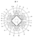
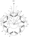
- Example 1 of the permanent-magnet-type rotary electric machine of this invention It is sectional drawing which shows Example 1 of the permanent-magnet-type rotary electric machine of this invention. It is sectional drawing which shows the shape of the rotor of the permanent magnet type rotary electric machine shown in FIG. It is principal part sectional drawing which shows the stator core shape of the stator of the permanent magnet type rotary electric machine shown in FIG. It is sectional drawing which shows the reference example of a permanent magnet type rotary electric machine. It is a figure which shows Example 2 of this invention, and is a longitudinal cross-sectional view of the compressor using the permanent magnet type rotary electric machine. It is a figure which shows Example 3 of this invention, and is sectional drawing which shows the shape of the rotor of a permanent magnet type rotary electric machine, and is a figure equivalent to FIG.
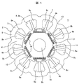
- Example 1 of the permanent magnet type rotating electrical machine of the present invention will be described with reference to FIGS. 1 is a sectional view showing a first embodiment of a permanent magnet type rotating electrical machine according to the present invention
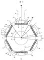
- FIG. 2 is a sectional view showing a shape of a rotor of the permanent magnet type rotating electrical machine shown in FIG. 1
- FIG. 3 is a permanent view shown in FIG.
- FIG. 4 is a cross-sectional view showing a main part of a stator core of a stator of a magnet-type rotating electrical machine
- FIG. 1 is a sectional view showing a first embodiment of a permanent magnet type rotating electrical machine according to the present invention
- FIG. 2 is a sectional view showing a shape of a rotor of the permanent magnet type rotating electrical machine shown in FIG. 1
- FIG. 3 is a permanent view shown in FIG.
- FIG. 4 is a cross-sectional view showing a main part of a stator core of a stator of a magnet-type rotating electrical machine
- the present invention is applied to a permanent magnet type rotating electrical machine constituted by a 6-pole rotor and a 9-slot stator (6-pole 9-slot).
- the ratio of the number of rotor poles to the number of slots in the stator is 2: 3, but the ratio between the number of other poles and the number of slots and the number of poles of the other rotor and the number of slots in the stator is used.
- the present invention can be similarly applied to a thing, and almost the same effect can be obtained.
- the number of poles of the rotor may be 4 poles or 8 poles.
- the permanent magnet type rotating electric machine shown in FIG. 4 includes a 4-pole rotor and a 6-slot stator.
- the permanent magnet type rotating electrical machine in the present embodiment is a so-called embedded magnet type rotating electrical machine in which a permanent magnet is embedded in a rotor core.
- axial direction indicates the rotational axis direction of the rotor
- radial direction indicates the radial direction of the rotor
- circumferential direction indicates the circumferential direction of the rotor.
- the sectional view of the permanent magnet type rotating electrical machine of this embodiment shown in FIG. 1 shows a section in a direction perpendicular to the rotation axis (the same applies to FIGS. 2 to 4 and 6 described later).
- the first embodiment operates as a permanent magnet type synchronous motor.
- a permanent magnet type rotating electrical machine 1 is arranged to rotate with a stator 2 and a predetermined gap (gap) inside the stator 2 and rotating with a shaft (not shown). It is composed of a child 3.
- the stator 2 includes a stator core 6 including an annular core back 5 and nine teeth 4 that protrude radially inward from the core back 5 and are arranged at substantially equal intervals along the circumferential direction. , And a concentrated winding armature winding 8 or the like wound so as to surround the teeth 4 in a slot 7 between the teeth 4 adjacent to each other in the circumferential direction. It is fixed to the closed container of the machine by shrink fitting or press fitting.
- the armature winding 8 is wound around the axial center of the tooth 4 radially arranged in the radial direction, and in the circumferential direction, a U-phase winding 8a, a V-phase winding 8b, W-phase windings 8c are arranged with a gap therebetween.
- the stator 2 is configured by laminating the stator cores 6 (magnetic steel plates) in the axial direction, and nine slots (9 slots) are formed between the adjacent teeth 4. Yes.
- the rotor 3 is composed of a rotor core 12 and six permanent magnets 14 embedded in the outer peripheral portion of the rotor core 12 and arranged at substantially equal intervals in the circumferential direction. Is a 6-pole rotor.
- a shaft hole 15 is formed in the center of rotation of the rotor 3, and a cylindrical shaft (not shown) is integrally fixed to the shaft hole 15, and the rotor 3 is an inner part of the stator 2. It is rotatably arranged on the peripheral surface side via a gap.
- the rotor 3 has 6 poles and the stator 2 has 9 slots (6 poles 9 slots).
- the angle is 120 degrees (mechanical angle is 40 degrees).
- the permanent magnet type rotating electrical machine 1 of the present embodiment when a three-phase alternating current is passed through the armature winding 8 composed of the three-phase windings 8a to 8c, a rotating magnetic field is generated. Due to this rotating magnetic field, the rotor 3 is rotated by electromagnetic force acting on the permanent magnet 14 and the rotor core 12 embedded in the rotor 3.
- stator core 6 and the rotor core 12 are: It is preferable to form a laminated body in which a plurality of thin plates made of magnetic steel plates such as silicon steel plates are stacked.
- FIG. 2 is a sectional view of the rotor of the permanent magnet type rotating electric machine according to the first embodiment of the present invention.
- the rotor 3 has the rotor core 12 in which a shaft hole 15 is formed at the center of rotation.
- a plurality of rectangular permanent magnet insertion holes 13 having an elongated cross section (six poles in the first embodiment) are formed.
- Each of the plurality of permanent magnet insertion holes 13 is inserted with a flat, single-letter permanent magnet 14 made of a magnet material, for example, rare earth neodymium.
- the direction of the magnetic flux generated by the magnetic pole of the permanent magnet 14, that is, the virtual axis connecting the longitudinal center (cross section center) of the permanent magnet 14 and the rotation center is the d axis (flux axis).
- the axis (electric axis between permanent magnets) that is electrically orthogonal to the d-axis, that is, the electrical angle, is defined as the q-axis.
- the rotor 3 is provided with one permanent magnet 14 per magnetic pole.
- the cross-sectional shape of the permanent magnet 14 is an elongated rectangular shape similar to the permanent magnet insertion hole 13, and the longitudinal direction of the permanent magnet 14 extends in a direction perpendicular to the d axis.
- the rotor core 12 of the rotor 3 is provided with a rotor recess 11 that is recessed inward on the q axis between the poles of adjacent permanent magnets 14.
- the rotor recess 11 suppresses the q-axis magnetic flux as will be described later.
- the rotor 3 that is, the rotor core 12, is located on the outer peripheral side of the rotor recess 11, and has an arcuate outermost periphery in which the gap length (gap) between the stator 2 and the teeth 4 is the shortest g 1.
- the magnetic pole surface of the rotor core 12 has a cut portion 12b connected to the end of the arcuate portion 12a, and the arcuate portion 12a passes through the cut portion 12b and the rotor concave portion. 11 is connected.
- a gap length g2 between the cut portion 12b and the teeth 4 of the stator 2 is configured to be wider than a gap length g1 between the arc-shaped portion 12a and the teeth 4 of the stator 2.
- the cut portion 12b is formed in a straight line shape, but is not necessarily limited to a straight line shape, and may be a curved surface shape.
- the angle ⁇ p3 of the arc-shaped portion 12a around the rotation center O of the rotor 3, that is, the angle ⁇ p3 at which two straight lines connecting both ends of the arc-shaped portion 12a and the rotation center O intersect is The angle is 90 ° to 120 °.
- the rotor concave portion 11 smoothly smoothes two linear portions 11b and 11c formed substantially parallel to the radial thickness direction of the permanent magnet 14 and the rotor inner peripheral side end portions of the two linear portions 11b and 11c.
- the curved portion 11a is connected between the ends facing the q-axis on the inner peripheral side magnetic pole surface of two adjacent permanent magnets located on both sides of the q-axis, that is, the latest It is located on the rotor inner peripheral side from the virtual straight line 9 connecting the contact portions.
- the starting position of the curved portion 11a is substantially located at the portion of the virtual straight line 9, but may be located at the rotor inner peripheral side of the virtual straight line 9.
- the start position of the curved portion 11a may be configured to be positioned on the outer peripheral side of the virtual straight line 9. good.
- the bottom of the rotor recess 11 in the radial direction is configured to be deeper than the inner peripheral side magnetic pole surface of the permanent magnet 14.
- the interval between the two straight portions 11b and 11c is configured to increase from the rotor inner peripheral side toward the rotor outer peripheral side.
- the cross-sectional area of the rotor recess 11 is configured to be larger than the cross-sectional area of the cut portion 12b.
- the angle between the end portions of the outer peripheral side magnetic pole surface of the permanent magnet 14 constituting one magnetic pole of the rotor 3 is ⁇ p1
- the two linear portions of the rotor recess 11 When the angle between the end portions of the outer peripheral side of the rotors 11b and 11c is ⁇ p2, in this embodiment, the angles ⁇ p1 and ⁇ p2 are 0.18 ⁇ ⁇ p2 / ⁇ p1 ⁇ 0.5 It is set to satisfy the relationship.
- the pitch of the slots 7 in the stator 2 having concentrated windings is 120 ° in electrical angle.
- the rotor 3 has an outer peripheral side of the permanent magnet insertion hole 13 (or the permanent magnet 14) (the arc-shaped portion 12a in the rotor core 12 and the outer peripheral side magnetic pole surface of the permanent magnet 14).
- the plurality of slits 10a to 10d are provided symmetrically so as to sandwich the d-axis on both the left and right sides separated by a predetermined distance from the d-axis. Further, no slit is provided on the d-axis and in the vicinity of the d-axis so that the magnetic flux easily passes through the vicinity of the d-axis.
- the slits 10a and 10b are arranged symmetrically with respect to the d-axis, and the slits 10c and 10d are arranged symmetrically with respect to the d-axis between the slits 10a and 10b.
- the distance between the slits 10c and 10d arranged closest to the d-axis is set to the minimum width of the tooth 4 in general.
- the distance between the end portions of 10d is set to the minimum width of the teeth 4 in general.
- the slits 10 a to 10 d are arranged so as to be inclined so that the magnetic flux of the permanent magnet 14 is collected on the teeth 4. That is, the direction in which the slits 10a to 10d go to the outer peripheral side is inclined inward from a direction parallel to the d-axis so as to make an acute angle with the d-axis. Since the induced electromotive force waveform can be made sine wave by such slits 10a to 10d, the armature current can be made sine wave accordingly, and the harmonic magnetic flux generated by the interaction between the induced electromotive force and the armature current is reduced. can do. That is, the slits 10a to 10d suppress the armature reaction and reduce the harmonic component of the magnetic flux in the rotating electric machine.
- the concentrated winding armature winding 8 is a winding arranged at an electrical angle of 120 degrees, so that harmonic components such as the fifth and seventh orders of the in-machine magnetic flux are large, causing vibration and noise.
- the pulsating torque and the radial electromagnetic excitation force are also increased.
- FIG. 4 shows a reference example similar to Patent Document 1 described above.
- the tip portion (tooth tip portion) 16 of the teeth 4 in the stator 2 has a central portion concentric with the rotor core 12, and both ends of the teeth tip portion 16 are linear. That is, it is kept away from the rotor core 12.
- the induced electromotive force waveform can be converted into a sine wave and the armature current can be converted into a sine wave, so that the harmonic magnetic flux generated by the interaction between the induced electromotive force and the armature current can be reduced. Torque and radial electromagnetic excitation force can be reduced.
- the shape of the stator 2 is configured as shown in FIG. That is, in this embodiment, as shown in FIG. 3, a stator concave portion 17 is provided on the outer peripheral side of the teeth 4 of the stator core 6.
- the stator 2 is fixed to a compressor frame (sealed container) or the like by shrink fitting or press fitting (see FIG. 5 to be described later). In this case, the contact portion between the frame and the stator 2 is fixed.
- An arc portion 5a on the outer periphery of the core back 5 of the core 6 is formed, and the stator 2 is fixed to the frame by the arc portion 5a.
- the arc portion 5 a fixed to the frame and the stator recess 17 formed on the outer peripheral side of the teeth 4 are provided. Yes.
- the stator recess 17 includes three straight portions (17a, 17b, 17c) along (parallel to) the width direction of the teeth 4 and two straight portions (17d) respectively connecting the end portions of the three straight portions. , 17e). That is, the stator concave portion 17 is connected to one of the circular arc portions 5a and parallel to the width direction of the teeth 4, and the circular arc portion is provided on the other side across the teeth. A second linear portion 17b connected to the circular arc portion and parallel to the width direction of the teeth, and a second linear portion 17b provided between the first and second linear portions and radially inward and parallel to the width direction of the teeth.
- stator recess 17 is not in contact with the frame.
- the distance between the left and right ends of the tooth tip 16 inside the slot 7 is L1
- the width of the tooth 4 is L2
- the arc portion 5a and the stator recess 17 provided on both sides of the stator recess 17 are provided.
- a straight line distance connecting the intersecting points (a distance of a portion not in contact with the frame on the back side of the teeth 4) is defined as L3.
- the distance L3 will be described in more detail.
- L2 ⁇ L1 ⁇ L3 It is configured to satisfy the relationship.
- the depth L4 of the stator recess 17 is configured to be shorter than the length of the teeth 4 and the thickness of the core back 5 so that the flow of effective magnetic flux in the rotating electrical machine is not impaired as much as possible.
- the first embodiment is a permanent magnet type rotating electric machine that combines the structure of the rotor 3 described in FIG. 2 and the structure of the stator 2 described in FIG. Since the harmonic component of the magnetic flux in the rotating electrical machine due to the influence can be sufficiently reduced, the generation of the pulsating torque and the radial electromagnetic excitation force can be suppressed to achieve a small size, high efficiency, and low noise. Further, it is possible to suppress pulsation torque and radial electromagnetic excitation force generated in the rotating electrical machine from being transmitted to the frame.
- this permanent magnet type rotating electrical machine 1 is used in a compressor constituting a refrigeration cycle, it is small and highly efficient. A low noise compressor can be obtained.
- the harmonic component of the magnetic flux can be reduced without reducing the slot cross-sectional area of the stator, a small-sized, high-efficiency, low-noise permanent magnet type rotating electrical machine and The effect which can obtain the used compressor is acquired.
- FIG. 5 is a longitudinal sectional view of a compressor using a permanent magnet type rotating electrical machine, showing the second embodiment.
- a compressor 20 shown in FIG. 5 includes a compression mechanism unit 21 that reduces the volume of a gas that is a working fluid such as a refrigerant, and an electric motor unit 22 that drives the compression mechanism unit 21, and the electric motor unit 22 is the above-described one.
- the permanent magnet type rotating electrical machine 1 of the first embodiment is mounted.
- the compressor 20 in the second embodiment is used in a refrigeration cycle apparatus such as an air conditioner, and the compression mechanism portion 21 and the electric motor portion 22 are accommodated in a cylindrical sealed container (frame) 23. ing. Further, R32 refrigerant is sealed as a working fluid in the sealed container 23.
- the compression mechanism portion 21 is constituted by a scroll compression mechanism including a fixed scroll 24 and a turning scroll 25, and the fixed scroll 24 is attached to a frame 26 fixed to the inner surface of the hermetic container 23 with a bolt or the like. Fastened by fastening means.
- the fixed scroll 24 includes an end plate 24a, a spiral fixed scroll wrap 24b formed so as to stand upright on the end plate 24a, a discharge port 24c formed in a substantially central portion of the end plate 24a, and the like.
- the orbiting scroll 25 includes an end plate 25a, a spiral orbiting scroll wrap 25b formed so as to stand upright on the end plate 25a, a boss portion 25c formed at the center of the back surface of the end plate 25a, and the like. Yes.
- the orbiting scroll 25 is meshed with the fixed scroll 24 and the electric motor unit (permanent magnet type rotating electrical machine) 22 rotates, whereby the orbiting scroll 25 is orbitally moved via the crankshaft 27 to perform a compression operation. .
- crankshaft 27 is inserted into a shaft hole 15 (see FIGS. 1 and 2) formed in the rotor 3 of the electric motor unit 22 and is configured integrally with the rotor 3.
- the crankshaft A crank portion (eccentric pin portion) 27a is formed at the upper end portion of 27.
- the crank portion 27 a of the crankshaft 27 is inserted into and engaged with the boss portion 25 c of the orbiting scroll 25.
- the crankshaft 27 is rotatably supported by a slide bearing (main bearing) 28 provided on the frame 26 and a ball bearing 30 provided on a lower frame 29 in the lower part of the sealed container 23.
- the crankshaft 27 also rotates, causing the orbiting scroll 25 to perform an orbiting motion via the crank portion 27a.
- the orbiting scroll 25 starts the orbiting motion, the refrigerant gas of the refrigeration cycle is sucked into the suction chamber formed on the outer peripheral side of the fixed scroll 24 from the suction pipe 31 and is formed by the fixed scroll 24 and the orbiting scroll 25 from here. After being confined in the compression chamber 32, it is compressed along with the orbiting motion of the orbiting scroll 25, moves to the center side, and is discharged from the discharge port 24 c to the discharge chamber above the sealed container 23.
- the compression chamber located on the outermost diameter side among the compression chambers 32 formed by the fixed scroll 24 and the orbiting scroll 25 moves toward the centers of the scroll members 24 and 25 along with the orbiting motion,
- the volume gradually decreases.
- the compression chamber 32 communicates with the discharge port 24c, and the compressed gas is discharged from the compression chamber 32 to the discharge chamber through the discharge port 24c.
- the discharged compressed refrigerant gas flows from the discharge chamber through the gas passage 33 provided on the outer peripheral side of the fixed scroll 24 and the frame 26 to the electric motor chamber side below the frame 26 and in the refrigerant gas.
- the oil is supplied to the refrigeration cycle from a discharge pipe 34 provided on the side wall of the sealed container 23.
- the separated oil is stored in an oil reservoir 35 formed in the lower part of the sealed container 23.
- the oil stored in the oil reservoir 35 passes through an oil hole 36 formed in the crankshaft 27 in the axial direction, and the centrifugal force due to the rotation of the crankshaft 27 and the difference between the discharge pressure and the low pressure side.
- the sliding bearing 28, the ball bearing 30, and the sliding portion of the compression mechanism 21 are supplied by pressure.
- 8 is an armature winding of the stator 2
- 37 is a balance weight
- 38 is a power supply terminal.
- the electric motor unit 22 composed of the permanent magnet type rotating electrical machine 1 is controlled by a separate inverter (not shown) and is rotated at a rotation speed suitable for the compression operation.
- Table 1 shows a conventional general permanent magnet having various rotor shapes and stator shapes only in the permanent magnet type rotating electric machine, with the same basic configuration as the compressor 20 of the second embodiment described above. It is the measurement result which conducted the auditory test of the noise by the compressor incorporating the rotary electric machine and the compressor carrying the rotary electric machine of the reference example shown in FIG.
- the frequency bands of annoying noises are roughly divided into three ranges: low, middle and high.
- the low frequency range is less than 1 kHz
- the middle frequency range is 1 kHz or more and less than 4 kHz
- the high frequency range is 4 kHz or more and 10 kHz or less.
- the noise component in the middle range which is particularly problematic in hearing, appears more prominently in a compressor equipped with a conventional general permanent magnet type rotating electrical machine (hereinafter also referred to as a conventional compressor).
- the compressor hereinafter also referred to as the compressor of the reference example
- the rotating electrical machine of the reference example shown in FIG. 4 has a reduction effect on the low-frequency and high-frequency noise components as compared with the conventional compressor.
- the audibility with respect to the mid-range noise component it was not sufficiently reduced.
- the lower order harmonic components such as the fifth order and the seventh order
- the relatively higher order such as the 25th order and 27th order components. It has been observed that the harmonic components of are greatly reduced. However, it has been found that the relatively middle harmonic components such as the 11th and 13th components and the 15th and 17th components are not reduced as the harmonic components of the magnetic flux in the rotating electrical machine.
- the lower-order and higher-order harmonic components of the magnetic flux in the rotating electric machine can be reduced and compared with the compressor according to the reference example. It was also found that the harmonic components in the target midrange could be significantly reduced compared to the compressor of the reference example. This is because, in the case of the compressor of the second embodiment, the harmonic component of the magnetic flux in the rotating electrical machine can be sufficiently reduced, and the pulsating torque and the radial electromagnetic excitation force in the rotating electrical machine are reduced by the compressor 20. This is because it is possible to suppress the transmission to the hermetic container (frame) 23.
- the overall noise value was 67.4 dB, whereas in the compressor of the second embodiment, the noise value was reduced to 64.3 dB. Has been.
- the compressor of the second embodiment it is possible to greatly reduce the noise component in the middle range, which is a problem particularly in hearing, and to reduce the overall noise value.
- the permanent magnet type rotating electrical machine 1 of the first embodiment described above is used for the compression chamber 20, a compact, high-efficiency, low-noise compressor 20 can be obtained. It can. That is, since the permanent magnet type rotating electric machine 1 has the rotor 3 having the structure described with reference to FIG. 2, the torque of the permanent magnet type rotating electric machine 1 can be made larger than that of the conventional one, particularly in the high speed range. Moreover, since the power factor fall by the influence of an armature reaction can also be suppressed, the torque fall in a high speed region is suppressed. For this reason, it becomes possible to achieve high efficiency and downsizing of the permanent magnet type rotating electrical machine.
- the efficiency of the compressor can be improved and energy can be saved.
- the operating range can be expanded, such as enabling high-speed operation of the compressor.
- the R410A refrigerant is sealed in the sealed container 23, and the ambient temperature of the permanent magnet type rotating electric machine is often 80 ° C. or higher.
- the ambient temperature since the R32 refrigerant having a smaller global warming potential is employed, the ambient temperature further increases.
- the permanent magnet 14, particularly a neodymium magnet has a residual magnetic flux density that decreases at a high temperature, and an armature current increases to ensure the same output, but the high-efficiency permanent magnet type rotating electrical machine 1 of the first embodiment is mounted. A reduction in efficiency can be suppressed by using the compressor.
- R32 is adopted as the refrigerant.
- refrigerants such as R32 and He have a larger leakage from the gap in the compressor than refrigerants such as R22, R407C, and R410A, and are particularly slow.
- the ratio of leakage to the amount of circulation increases, which reduces efficiency.
- the compression mechanism is downsized and the rotational speed is increased to obtain the same circulation, leakage loss can be reduced.
- the compressor equipped with the permanent magnet type rotating electrical machine 1 of the first embodiment it is possible to increase the maximum torque and the maximum rotation speed, and it is possible to reduce the loss in a high speed region.
- the compressor according to the second embodiment is particularly effective when a refrigerant that easily leaks, such as R32 or He, is used as the refrigerant, and the efficiency can be improved.
- stator concave portion 17 having a large area is provided on the outer periphery of the stator 2 in the permanent magnet type rotating electrical machine 1, an airtight container (frame) 23 is provided.
- Lubricating oil that has reached the upper surface of the stator 2 along the inner peripheral surface easily passes through the stator recess 17. As a result, it is possible to reduce the oil rise that the amount of lubricating oil in the compressor is insufficient during high-speed operation.
- R32 is used as a refrigerant, but the present invention is not limited to the type of refrigerant.
- the compressor is a scroll compressor.
- the present invention can be similarly applied to a compressor having another compression mechanism such as a rotary compressor. is there.
- FIG. 6 is a diagram illustrating the third embodiment, which is a cross-sectional view illustrating the shape of the rotor of the permanent magnet type rotating electrical machine, and corresponds to FIG. 2 described above.
- FIG. 6 the same parts as those in FIG. 2 are denoted by the same reference numerals, description thereof is omitted, and different parts are described.
- the third embodiment is different from the rotor 3 shown in FIG. 2 of the first embodiment, and includes two permanent magnets 14A per magnetic pole of the rotor 3A.
- the two permanent magnets 14 ⁇ / b> A are arranged in a convex V shape with respect to the shaft hole 15. That is, the cross sections of the two permanent magnets 14A have the same shape as that of the first embodiment, but are arranged in a convex V shape toward the rotation center O of the rotor 3 with the d axis as the axis of symmetry. As a result, high torque is achieved.
- the other configuration of the rotor 3A in the third embodiment is the same as that of the rotor 3 of the first embodiment.
- the rotor recess 11 is provided, and the values of the angles ⁇ p1, ⁇ p2, ⁇ p3, etc. in the rotor 3A are similarly configured.
- the harmonics of the magnetic flux in the rotating electric machine due to the influence of the armature reaction. Since the components can be sufficiently reduced, the generation of pulsation torque and radial electromagnetic excitation force can be suppressed to achieve a small size, high efficiency, and low noise. Further, it is possible to suppress pulsation torque and radial electromagnetic excitation force generated in the rotating electrical machine from being transmitted to the frame. Furthermore, also in the third embodiment, as in the first embodiment, it is possible to suppress the torque reduction in the high speed range, and from this point, it becomes possible to increase the efficiency and miniaturization of the permanent magnet type rotating electric machine. 1 can be obtained.
- SYMBOLS 1 Permanent magnet type rotary electric machine (drive motor), 2 ... Stator, 3, 3A ... Rotor, 4 ... Teeth, 5 ... Core back, 5a ... Arc part, 5b ... Stator recessed part, 6 ... Stator core 7 ... slot, 8 armature winding, 8a ... U phase winding, 8b ... V phase winding, 8c ... W phase winding, 9 ... virtual straight line, 10a, 10b, 10c, 10d ... slit, 11 ... rotation Child concave part, 11a ... curve part, 11b, 11c ... linear part, 12 ... rotor core, 12a ... arc-shaped part, 12b ...
- Crank part, 28 Sliding bearing (main bearing), 29 ... Lower frame, 30 ... Ball bearing, 31 ... Suction pipe, 32 ... Compression chamber, 33 ... Gas passage, 34 ... Discharge pipe, 35 ... oil retaining part, 36 ... oil hole, 37 ... balance weight, 38 ... power terminal.
Landscapes
- Engineering & Computer Science (AREA)
- Power Engineering (AREA)
- Iron Core Of Rotating Electric Machines (AREA)
- Permanent Field Magnets Of Synchronous Machinery (AREA)
- Permanent Magnet Type Synchronous Machine (AREA)
- Compressor (AREA)
Priority Applications (1)
| Application Number | Priority Date | Filing Date | Title |
|---|---|---|---|
| CN201780069174.5A CN109923757B (zh) | 2016-11-28 | 2017-11-01 | 永久磁铁式旋转电机及使用永久磁铁式旋转电机的压缩机 |
Applications Claiming Priority (2)
| Application Number | Priority Date | Filing Date | Title |
|---|---|---|---|
| JP2016230314A JP6381613B2 (ja) | 2016-11-28 | 2016-11-28 | 永久磁石式回転電機及びそれを用いる圧縮機 |
| JP2016-230314 | 2016-11-28 |
Publications (1)
| Publication Number | Publication Date |
|---|---|
| WO2018096887A1 true WO2018096887A1 (ja) | 2018-05-31 |
Family
ID=62195878
Family Applications (1)
| Application Number | Title | Priority Date | Filing Date |
|---|---|---|---|
| PCT/JP2017/039503 Ceased WO2018096887A1 (ja) | 2016-11-28 | 2017-11-01 | 永久磁石式回転電機及びそれを用いる圧縮機 |
Country Status (4)
| Country | Link |
|---|---|
| JP (1) | JP6381613B2 (enExample) |
| CN (1) | CN109923757B (enExample) |
| TW (1) | TWI655828B (enExample) |
| WO (1) | WO2018096887A1 (enExample) |
Cited By (3)
| Publication number | Priority date | Publication date | Assignee | Title |
|---|---|---|---|---|
| CN111697729A (zh) * | 2020-07-16 | 2020-09-22 | 珠海格力节能环保制冷技术研究中心有限公司 | 电机、压缩机及制冷设备 |
| WO2023021778A1 (ja) * | 2021-08-17 | 2023-02-23 | 日立グローバルライフソリューションズ株式会社 | 回転電機、電動送風機、及び電気掃除機 |
| CN118728722A (zh) * | 2024-06-20 | 2024-10-01 | 珠海格力节能环保制冷技术研究中心有限公司 | 转子式压缩机、空调器 |
Families Citing this family (7)
| Publication number | Priority date | Publication date | Assignee | Title |
|---|---|---|---|---|
| KR20220002592A (ko) | 2019-12-11 | 2022-01-06 | 안후이 메이즈 프리시전 매뉴팩처링 컴퍼니 리미티드 | 모터, 압축기 및 냉방기기 |
| CN110932422B (zh) * | 2019-12-11 | 2022-04-01 | 安徽美芝精密制造有限公司 | 电机、压缩机及制冷设备 |
| JP6793888B1 (ja) * | 2020-02-07 | 2020-12-02 | 三菱電機株式会社 | 回転電機 |
| CN113872349B (zh) * | 2021-10-14 | 2023-01-31 | 广东美芝制冷设备有限公司 | 定子结构、电机结构、压缩机结构和制冷设备 |
| CN113872348B (zh) * | 2021-10-14 | 2023-11-17 | 广东美芝制冷设备有限公司 | 定子结构、电机结构、压缩机结构和制冷设备 |
| WO2025203429A1 (ja) * | 2024-03-28 | 2025-10-02 | 三菱電機株式会社 | ステータ、電動機、圧縮機および冷凍サイクル装置 |
| WO2025203418A1 (ja) * | 2024-03-28 | 2025-10-02 | 三菱電機株式会社 | ステータ、電動機、圧縮機および冷凍サイクル装置 |
Citations (6)
| Publication number | Priority date | Publication date | Assignee | Title |
|---|---|---|---|---|
| JP2002078255A (ja) * | 2000-08-29 | 2002-03-15 | Hitachi Ltd | 永久磁石式回転電機 |
| JP2002142390A (ja) * | 2000-11-06 | 2002-05-17 | Matsushita Electric Ind Co Ltd | モータ及びそれを用いた圧縮機 |
| JP2005080418A (ja) * | 2003-09-01 | 2005-03-24 | Daikin Ind Ltd | 圧縮機、電動機及びその固定子 |
| JP2009299676A (ja) * | 2008-01-24 | 2009-12-24 | Daikin Ind Ltd | 圧縮機 |
| JP2014217189A (ja) * | 2013-04-26 | 2014-11-17 | 株式会社日立産機システム | 永久磁石同期機およびこれを用いた圧縮機 |
| CN104333153A (zh) * | 2014-11-24 | 2015-02-04 | 广东美芝制冷设备有限公司 | 用于电机的定子及其制造方法、电机 |
Family Cites Families (4)
| Publication number | Priority date | Publication date | Assignee | Title |
|---|---|---|---|---|
| JP5462011B2 (ja) * | 2010-01-28 | 2014-04-02 | 株式会社日立産機システム | 永久磁石式回転電機及びそれを用いた圧縮機 |
| TWI477034B (zh) * | 2011-12-01 | 2015-03-11 | Adlee Powertronic Co Ltd | Built-in permanent magnet motor |
| JP2015208053A (ja) * | 2014-04-17 | 2015-11-19 | 日立アプライアンス株式会社 | 永久磁石式回転電機及びそれを用いた圧縮機 |
| CN104882978B (zh) * | 2015-05-07 | 2018-03-20 | 东南大学 | 一种低转矩脉动高效率永磁电机定转子结构 |
-
2016
- 2016-11-28 JP JP2016230314A patent/JP6381613B2/ja active Active
-
2017
- 2017-11-01 WO PCT/JP2017/039503 patent/WO2018096887A1/ja not_active Ceased
- 2017-11-01 CN CN201780069174.5A patent/CN109923757B/zh not_active Expired - Fee Related
- 2017-11-27 TW TW106141096A patent/TWI655828B/zh active
Patent Citations (6)
| Publication number | Priority date | Publication date | Assignee | Title |
|---|---|---|---|---|
| JP2002078255A (ja) * | 2000-08-29 | 2002-03-15 | Hitachi Ltd | 永久磁石式回転電機 |
| JP2002142390A (ja) * | 2000-11-06 | 2002-05-17 | Matsushita Electric Ind Co Ltd | モータ及びそれを用いた圧縮機 |
| JP2005080418A (ja) * | 2003-09-01 | 2005-03-24 | Daikin Ind Ltd | 圧縮機、電動機及びその固定子 |
| JP2009299676A (ja) * | 2008-01-24 | 2009-12-24 | Daikin Ind Ltd | 圧縮機 |
| JP2014217189A (ja) * | 2013-04-26 | 2014-11-17 | 株式会社日立産機システム | 永久磁石同期機およびこれを用いた圧縮機 |
| CN104333153A (zh) * | 2014-11-24 | 2015-02-04 | 广东美芝制冷设备有限公司 | 用于电机的定子及其制造方法、电机 |
Cited By (3)
| Publication number | Priority date | Publication date | Assignee | Title |
|---|---|---|---|---|
| CN111697729A (zh) * | 2020-07-16 | 2020-09-22 | 珠海格力节能环保制冷技术研究中心有限公司 | 电机、压缩机及制冷设备 |
| WO2023021778A1 (ja) * | 2021-08-17 | 2023-02-23 | 日立グローバルライフソリューションズ株式会社 | 回転電機、電動送風機、及び電気掃除機 |
| CN118728722A (zh) * | 2024-06-20 | 2024-10-01 | 珠海格力节能环保制冷技术研究中心有限公司 | 转子式压缩机、空调器 |
Also Published As
| Publication number | Publication date |
|---|---|
| TWI655828B (zh) | 2019-04-01 |
| JP6381613B2 (ja) | 2018-08-29 |
| TW201834359A (zh) | 2018-09-16 |
| CN109923757B (zh) | 2020-10-16 |
| CN109923757A (zh) | 2019-06-21 |
| JP2018088746A (ja) | 2018-06-07 |
Similar Documents
| Publication | Publication Date | Title |
|---|---|---|
| JP6381613B2 (ja) | 永久磁石式回転電機及びそれを用いる圧縮機 | |
| JP5259934B2 (ja) | 永久磁石式回転電機及びそれを用いた圧縮機 | |
| JP5372468B2 (ja) | 永久磁石式回転電機及びそれを用いた圧縮機 | |
| JP5462011B2 (ja) | 永久磁石式回転電機及びそれを用いた圧縮機 | |
| TWI569560B (zh) | A permanent magnet type rotating machine, and a compressor using the same | |
| CN105594099B (zh) | 永磁铁埋入型电动机、压缩机以及制冷空调装置 | |
| JP6037362B2 (ja) | 永久磁石埋込型電動機、圧縮機及び冷凍空調装置 | |
| JP5208662B2 (ja) | 永久磁石式回転電機及びそれを用いた圧縮機 | |
| WO2018128006A1 (ja) | 永久磁石式回転電機、及び、それを用いた圧縮機 | |
| JP2016100927A (ja) | 永久磁石式回転電機及びそれを用いた圧縮機 | |
| JP6470598B2 (ja) | 永久磁石式回転電機、並びにそれを用いる圧縮機 | |
| CN111953166A (zh) | 永磁式旋转电机以及使用该旋转电机的压缩机 | |
| JP6416449B1 (ja) | 永久磁石式回転電機及びそれを用いた圧縮機 | |
| JP2011015500A (ja) | 電動機の回転子 | |
| WO2018225293A1 (ja) | 永久磁石式回転電機及びそれを用いた圧縮機 | |
| JP2017055583A (ja) | 永久磁石式回転電機、並びにそれを用いる圧縮機 | |
| JP4969216B2 (ja) | 永久磁石同期電動機及び圧縮機 | |
| WO2023175670A1 (ja) | 電動機の固定子、圧縮機及び冷凍空調装置 | |
| WO2020044419A1 (ja) | 永久磁石式回転電機及びそれを用いた圧縮機 |
Legal Events
| Date | Code | Title | Description |
|---|---|---|---|
| 121 | Ep: the epo has been informed by wipo that ep was designated in this application |
Ref document number: 17874249 Country of ref document: EP Kind code of ref document: A1 |
|
| NENP | Non-entry into the national phase |
Ref country code: DE |
|
| 122 | Ep: pct application non-entry in european phase |
Ref document number: 17874249 Country of ref document: EP Kind code of ref document: A1 |