WO2018096648A1 - Accélérateur et dispositif de projection de faisceau de particules - Google Patents
Accélérateur et dispositif de projection de faisceau de particules Download PDFInfo
- Publication number
- WO2018096648A1 WO2018096648A1 PCT/JP2016/084969 JP2016084969W WO2018096648A1 WO 2018096648 A1 WO2018096648 A1 WO 2018096648A1 JP 2016084969 W JP2016084969 W JP 2016084969W WO 2018096648 A1 WO2018096648 A1 WO 2018096648A1
- Authority
- WO
- WIPO (PCT)
- Prior art keywords
- accelerator
- ion source
- magnetic pole
- magnetic
- ion
- Prior art date
Links
Images


Classifications
-
- G—PHYSICS
- G21—NUCLEAR PHYSICS; NUCLEAR ENGINEERING
- G21K—TECHNIQUES FOR HANDLING PARTICLES OR IONISING RADIATION NOT OTHERWISE PROVIDED FOR; IRRADIATION DEVICES; GAMMA RAY OR X-RAY MICROSCOPES
- G21K5/00—Irradiation devices
- G21K5/04—Irradiation devices with beam-forming means
-
- H—ELECTRICITY
- H05—ELECTRIC TECHNIQUES NOT OTHERWISE PROVIDED FOR
- H05H—PLASMA TECHNIQUE; PRODUCTION OF ACCELERATED ELECTRICALLY-CHARGED PARTICLES OR OF NEUTRONS; PRODUCTION OR ACCELERATION OF NEUTRAL MOLECULAR OR ATOMIC BEAMS
- H05H13/00—Magnetic resonance accelerators; Cyclotrons
- H05H13/02—Synchrocyclotrons, i.e. frequency modulated cyclotrons
-
- H—ELECTRICITY
- H05—ELECTRIC TECHNIQUES NOT OTHERWISE PROVIDED FOR
- H05H—PLASMA TECHNIQUE; PRODUCTION OF ACCELERATED ELECTRICALLY-CHARGED PARTICLES OR OF NEUTRONS; PRODUCTION OR ACCELERATION OF NEUTRAL MOLECULAR OR ATOMIC BEAMS
- H05H13/00—Magnetic resonance accelerators; Cyclotrons
- H05H13/04—Synchrotrons
-
- H—ELECTRICITY
- H05—ELECTRIC TECHNIQUES NOT OTHERWISE PROVIDED FOR
- H05H—PLASMA TECHNIQUE; PRODUCTION OF ACCELERATED ELECTRICALLY-CHARGED PARTICLES OR OF NEUTRONS; PRODUCTION OR ACCELERATION OF NEUTRAL MOLECULAR OR ATOMIC BEAMS
- H05H7/00—Details of devices of the types covered by groups H05H9/00, H05H11/00, H05H13/00
- H05H7/08—Arrangements for injecting particles into orbits
Definitions
- the present invention relates to an accelerator for accelerating ions such as protons and carbon and a particle beam irradiation apparatus including the accelerator.
- Patent Document 1 describes the use of an ion source installed outside in a cyclotron accelerator. This Patent Document 1 describes a device configuration from when an ion beam is incident on a cyclotron from an external ion source.
- Patent Document 1 described above describes a cyclotron accelerator having an external ion source type incident system for injecting an ion beam from the outside.
- the arrangement of the ion source described in Patent Document 1 requires many lens mechanisms on the beam line. For this reason, there has been a problem that the apparatus becomes complicated and large.
- An object of the present invention is to provide an external ion source type accelerator that can shorten a beam line and does not use a large-scale apparatus, and a particle beam irradiation apparatus including the accelerator.
- the present invention includes a plurality of means for solving the above-described problems.
- an ion source having at least a discharge chamber, a coil, and a magnetic path, and an ion beam extracted from the ion source are accelerated.
- a high-frequency accelerating electrode and a magnetic pole for generating a magnetic field formed so as to generate a circular orbit of the ion beam, wherein the discharge chamber and the magnetic path of the ion source have the magnetic pole in a vertical direction.
- the magnetic pole is arranged inside the outer peripheral surface of the magnetic pole.
- an ion source having at least a discharge chamber, a coil, and a magnetic path, and a high-frequency acceleration electrode for accelerating an ion beam extracted from the ion source are disposed so as to face each other, and a magnetic field is generated.
- a pair of magnetic poles formed in between, the magnetic pole has a depression on the opposite side of the surface facing the other magnetic pole, and the discharge chamber and the magnetic path of the ion source are the It is arranged in the recess of the magnetic pole.
- an external ion source type accelerator that can shorten the beam line and does not use a large-scale apparatus and a particle beam irradiation apparatus including the accelerator are provided.
- FIG. 1 It is a figure which shows the whole structure of the particle beam irradiation apparatus of Example 1 of this invention. It is a figure which shows the side surface cross section of the accelerator shown in FIG. It is a figure which shows the cross section of the accelerator shown in FIG. It is a figure which shows the outline of the side surface around the ion source of the accelerator of Example 1.
- FIG. It is a figure which shows the magnetic field analysis result of the ion source installation part in Example 1.
- FIG. It is a figure which shows the analysis result of the longitudinal magnetic field in the center position of the ion source installation part in Example 1.
- FIG. It is a figure which shows the cross section of the accelerator of Example 2 of this invention. It is a figure which shows the side surface cross section of the accelerator shown in FIG.
- FIG. 1 is a diagram showing the overall configuration of the particle beam irradiation apparatus of the present embodiment.
- the particle beam irradiation apparatus 100 includes a cyclotron accelerator 50, a beam transport system 52, an irradiation apparatus 54, a treatment table 40, and a control apparatus 56.
- ions generated by the ion source 3 are accelerated by an accelerator 50 to be an ion beam.
- the accelerated ion beam is emitted from the accelerator 50 and transported to the irradiation device 54 by the beam transport system 52.
- the transported ion beam is shaped by the irradiation device 54 so as to match the shape of the affected area, and a predetermined amount is irradiated to the target of the patient 45 lying on the treatment table 40.
- each device and equipment in the particle beam irradiation apparatus 100 including the accelerator 50 is controlled by the control device 56.
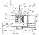
- FIG. 2 is a side sectional view of the accelerator of the present embodiment
- FIG. 3 is a transverse sectional view.
- the cyclotron accelerator 50 includes a main magnetic pole 1, an annular coil 2, a vacuum vessel 6, a high-frequency acceleration electrode 7, an ion source 3, a beam extraction / focusing unit 4, and an inflector 5. Is done.
- the main magnetic pole 1 is a pair of magnetic bodies installed so as to face each other, and is made of, for example, iron.
- the main magnetic pole 1 is provided with a convex magnetic pole 10 between the opposing magnetic poles so as to generate a circular orbit 9 of the beam, and an isochronous magnetic field is generated therebetween.
- the magnetic pole B0 is generated by the convex magnetic pole 10, and the focusing force of the circulating ion beam is increased, contributing to stable circulation.
- Opposing upper and lower surfaces between the magnetic pole gaps where the magnetic field B0 is generated are symmetrical.
- the vacuum vessel 6 is sandwiched between the main poles 1 and forms a single vacuum vessel as a whole and constitutes a magnetic circuit.
- the vacuum vessel 6 is a nonmagnetic material.
- the annular coil 2 is installed on the atmosphere side from the vacuum vessel 6 and generates a magnetic field between the pair of upper and lower main magnetic poles 1.
- the annular coil 2 can generate a magnetic field in the same manner whether it is a coil made of a normal conducting material or a coil made of a superconducting material.
- the annular coil 2 may be installed in the vacuum vessel 6 and is not particularly defined.
- a depression 1B is formed on the outer peripheral surface 1A side opposite to the surface of the main magnetic pole 1 facing the other main magnetic pole 1, and the ion source 3 and the beam extraction and focusing section 4 are formed. Is disposed inside the recess 1B. That is, the main components constituting the ion source 3 and the beam extraction and focusing unit 4 are located inside the main magnetic pole 1 from the outer peripheral surface 1A and outside the convex magnetic pole 10 when the main magnetic pole 1 is viewed from the vertical cross section. Is arranged. Ions generated by the beam extraction and focusing unit 4 are extracted from the ion source 3. Details of the ion source 3 and the beam extraction focusing unit 4 will be described later.
- the ion source 3 and the beam extraction and focusing unit 4 can be restrained from beam divergence by arranging them as close to the orbit 9 as possible, no other means for shaping the beam is required and the number of components is reduced. Can do.
- the vertical distance (mainly the convex magnetic pole 10) from the beam extraction unit 120 (see FIG. 4) of the beam extraction and focusing unit 4 to the inflector 5 is obtained.
- a set of focusing lenses 200 (see FIG. 4) is arranged according to the gap).
- the converging lens 200 need not be provided when the vertical distance from the beam extraction unit 120 (see FIG. 4) to the inflector 5 is sufficiently small. Often it is sufficient, but two or more can be provided.
- the ion source 3 and the beam extraction / condensing unit 4 can be arranged so as to be accommodated on the inner peripheral surface side of the main magnetic pole 1 in the depression provided in the lower main magnetic pole 1.
- the ion beam extracted by the beam extraction and focusing section 4 is deflected from the vertical to the horizontal direction by the inflector 5 arranged at the center of the orbit 9.
- the inflector 5 is a device that deflects an ion beam using an electric field so as not to disturb the main magnetic field B0.
- the ion beam deflected in the horizontal direction by the inflector 5 is accelerated by the high frequency acceleration electrode 7 and accelerated while drawing a spiral orbit 9 by the action of the magnetic field of the convex magnetic pole 10 and the electric field of the high frequency acceleration electrode 7. Is extracted from the orbit 9 and output to the outside.
- FIG. 4 is a diagram showing details of the ion source 3 and the beam extraction and focusing unit 4 of FIG.
- the ion source 3 is a microwave ion source using a microwave 130 for plasma generation, and includes a waveguide 101, a magnetic path 103, a coil 102, a discharge chamber 105, an introduction window 109, and an extraction electrode 110. , Flange 111 and insulator 104.
- the ion source 3 is disposed on the inner side of the recess 1B formed on the outer peripheral surface 1A side of the main magnetic pole 1 as described above.
- the discharge chamber 105 and the portion of the magnetic path 103 that shields the discharge chamber 105 may be disposed inside the main magnetic pole 1. Is not necessarily arranged inside the main pole 1, but it is desirable that other configurations are also arranged inside the main pole 1.
- the beam extraction focusing unit 4 includes a beam extraction unit 120 including a deceleration electrode 107, an insulator 106, and a ground electrode 108, and a focusing lens 200 including a lens electrode 201 and an exit hole 202.
- the microwave 130 is introduced into the vacuum discharge chamber 105 from the waveguide 101 through the introduction window 109, and the source gas is introduced from the gas supply source (not shown), and the introduced gas is converted into the microwave.
- Plasma is generated by being ionized by an electric field and a magnetic field generated by the coil 102.
- the waveguide 101 is a tube that supplies a microwave supplied from a microwave transmission source (not shown) to the inside of the ion source 3, and is made of iron.
- the waveguide 101 may be aluminum or copper, but is preferably made of iron because it is connected to the ion source 3 disposed inside the main magnetic pole 1.
- the frequency of the microwave 130 is, for example, 2.45 GHz (GHz).
- the introduction window 109 is made of an insulating material having a low dielectric constant so as to reduce the reflection of the microwave 130, and is made of, for example, quartz, boron nitride (BN), aluminum nitride, or the like.
- the discharge chamber 105 is made of a non-magnetic metallic material, and the inner peripheral side is a vacuum where plasma is generated.
- the coil 102 is disposed around the discharge chamber 105, and a magnetic path 103 is formed so as to surround the coil 102.
- the magnetic path 103 is a magnetic body shaped to cover the discharge chamber 105 and is made of, for example, iron. This magnetic path 103 prevents the magnetic field leaking from the main pole 1 from affecting the discharge chamber 105.
- the coil 102 can be adjusted independently, and the magnetic field generated in the discharge chamber 105 is adjusted. Although two coils 102 are used in FIG. 4, a magnetic field can be generated with one or three coils. In the case of one, the magnetic field distribution in the discharge chamber 105 can be adjusted by appropriately forming the shape of the magnetic path 103. The coil 102 can be replaced with a permanent magnet.
- FIG. 5 shows a two-dimensional magnetic field analysis result when a space for installing the ion source 3 is provided in the main magnetic pole 1 and the magnetic path 103 and the coil 102 are installed therein.
- the current value of the annular coil 2 was determined and analyzed so that a magnetic field of about 1.3 Tesla (T) was generated in the gap between the magnetic poles of the main magnetic pole 1.
- FIG. 6 shows the magnetic field distribution at the position of the central portion 160 shown in FIG.
- the horizontal axis indicates the vertical position of the central portion 160, and the vertical axis indicates the vertical magnetic field strength at that position.
- the insulator 104 insulates and supports the waveguide 101, the magnetic path 103, the coil 102, the discharge chamber 105, the introduction window 109, and the extraction electrode 110 in the ion source 3.
- the insulator 104 is not particularly limited as long as it is an insulating material.
- the extraction electrode 110 is an electrode disposed at the lower part of the discharge chamber 105 and is a magnetic material. By making the extraction electrode 110 magnetic, the magnetic field distribution in the discharge chamber 105 can be easily made effective for plasma generation.
- a positive voltage for example, 30 to 60 kilovolts (kV) is applied to the flange 111 of the ion source 3 by the extraction power supply 300, and a negative voltage, for example, ⁇ 2 to ⁇ 10 kilovolts (kV) is applied to the deceleration electrode 107 by the deceleration power supply 301.
- kV kilovolts
- a negative voltage for example, ⁇ 2 to ⁇ 10 kilovolts (kV) is applied to the deceleration electrode 107 by the deceleration power supply 301.
- the deceleration electrode 107 is disposed below the magnetic path 103, the coil 102, the discharge chamber 105 and the like that are insulated and supported by the insulator 104.
- the deceleration electrode 107 and the like are fixed to the ground electrode 108 by the insulator 106, and further, the main magnetic pole. 1 is fixed.
- a focusing lens (beam focusing portion) 200 including a lens electrode 201 and an exit hole 202 is attached to the ground electrode 108 in the beam extraction direction.
- the focusing lens 200 focuses the ion beam extracted from the ion source 3.
- the beam extraction focusing unit 4 is formed by integrating the focusing lens 200, the ground electrode 108, the deceleration electrode 107, and the like.
- a voltage is applied to the lens electrode 201 by a lens power source 302.
- the voltage is a positive value that does not exceed the voltage of the extraction power supply 300.
- the ion beam extracted from the ion source 3 is focused by a focusing lens 200 having a lens electrode 201 and taken out from an exit hole 202, and then the beam is projected between the convex magnetic poles 10 facing the main magnetic pole 1 by the inflector 5. Introduced into the gap.
- the beam can be focused before the ion beam extracted from the ion source 3 diverges, so that the voltage of the lens power supply 302 is kept low. Can also reduce the capacity of the power supply.
- the above-described particle beam irradiation apparatus 100 includes the accelerator 50 and the irradiation apparatus 54 that irradiates the ion beam emitted from the accelerator 50.
- the accelerator 50 generates an ion source 3 having at least a discharge chamber 105, a coil 102, and a magnetic path 103, a high-frequency acceleration electrode 7 for accelerating an ion beam extracted from the ion source 3, and a beam orbit 9. And a pair of main magnetic poles 1 disposed so as to face each other.
- the main magnetic pole 1 has a recess 1B on the surface on the outer peripheral surface 1A side opposite to the surface facing the other main magnetic pole 1, and the discharge chamber 105 and the ion source 3
- the magnetic path 103 is disposed inside the outer peripheral surface 1A of the main magnetic pole 1 when the main magnetic pole 1 is viewed from the vertical cross section, that is, is disposed in the recess 1B of the main magnetic pole 1.
- the main configuration of the ion source 3 is arranged in the recess 1B on the inner side of the outer peripheral surface 1A of the main magnetic pole 1. Therefore, the beam line after extraction from the ion source 3 can be greatly shortened compared to the conventional external ion source type as described in Patent Document 1, although it is an external ion source type, so that it is complicated and large. It is possible to provide a small accelerator capable of reducing the number of components without using a simple device. Moreover, since it is an external ion source type, the effect that the access at the time of a maintenance, replacement
- the ion source 3 has the magnetic path 103 and the discharge chamber 105 and the magnetic path 103 are disposed in the recess 1B on the inner side of the outer peripheral surface 1A of the main magnetic pole 1, the ion source is provided in the main magnetic pole 1. Even when 3 is installed, the influence of the leakage magnetic field of the main magnetic pole 1 can be blocked. Therefore, it is possible to prevent a problem that has been found by the inventor's examination that the ion source cannot be sufficiently generated simply by disposing the ion source on the inner side of the outer peripheral surface 1A of the main magnetic pole 1.
- the main magnetic pole 1 has a convex magnetic pole 10, and since the discharge chamber 105 and the magnetic path 103 in the ion source 3 are arranged outside the convex magnetic pole 10, it is difficult to access during maintenance such as replacement.
- the arrangement of the ion source of the external ion source type that is easy to access without the arrangement close to the internal ion source type is more easily obtained, and the effect that the maintenance is easy while shortening the beam line is more reliably obtained. be able to.
- the beam can be focused even if the beam diverges after the beam is extracted from the ion source 3.
- the ion source 3 is a microwave ion source, it can be a long-life ion source, and further improvement in maintainability such as reduction in replacement frequency can be achieved.
- the waveguide 101 is further connected to the ion source 3 and the waveguide 101 is made of iron, the magnetic field generated by the coil 102 can be concentrated in the discharge chamber 105 and the main magnetic pole can be concentrated. 1 can further suppress the leakage magnetic field from entering the inside of the discharge chamber 105, and the ion generation efficiency in the ion source 3 can be improved.
- a synchrocyclotron accelerator that uses a magnetic field that is not an isochronous magnetic field can be used instead of the cyclotron accelerator that uses an isochronous magnetic field as described above.
- the synchrocyclotron accelerator is a type of accelerator that is an improvement of the cyclotron. It accelerates repeatedly by applying a high-frequency electric field to charged particles that move circularly between large magnetic poles. At high speed, the mass of the accelerated particle increases due to relativistic effects, and the period of the circular motion of the charged particle in the magnetic field increases in proportion to the mass. The shift of the period from the high frequency voltage caused by this is removed by modulating the frequency.
- the ion source 3 and the beam extraction / focusing section 4 can be arranged in the main magnetic pole 1 and the same effect can be obtained.
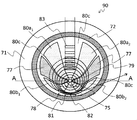
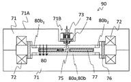
- FIG. 7 is a diagram showing a cross section of the accelerator
- FIG. 8 is a diagram showing a cross section AA of FIG.
- the accelerator 90 includes an ion source 73, a high-frequency acceleration electrode 77, a main magnetic pole 71, a local magnetic field generator 83, a vacuum vessel 76, and an annular coil 72. And a take-out septum 81.
- a high-frequency acceleration electrode 77 having a hollow inside is disposed symmetrically on the concave magnetic pole 80c so that a high-frequency power is applied from the outside by a high-frequency power source. Using the electric field generated by the high frequency, the high frequency acceleration electrode 77 accelerates the ion beam extracted from the ion source 73.
- the vacuum vessel 76 is arranged so as to be sandwiched between the main magnetic poles 71, and forms a single vacuum vessel as a whole and forms a main magnetic field B0 in the magnetic pole gap by forming a magnetic circuit.
- the vacuum container 76 is a nonmagnetic material.
- the annular coil 72 is installed on the atmosphere side of the vacuum vessel 76 and is a coil for causing the main magnetic pole 71 to generate the main magnetic field B0 in the magnetic pole gap between the main magnetic poles 71.
- the annular coil 72 may be a coil made of a normal conducting material or a coil made of a superconducting material.
- the main magnetic pole 71 has convex magnetic poles 80a 1 , 80a 2 , 80b 1 , 80b 2 and a concave magnetic pole 80c.
- the main magnetic pole 71 has a convex magnetic pole 80a 1 and a convex magnetic pole 80a. 2 and are symmetrical, and the convex pole 80b 1 and the convex pole 80b 2 has a structure symmetrical.
- the convex pole 80a 1 and the convex pole 80b 1 and is vertically asymmetrical
- the convex pole 80a 2 and the convex pole 80b 2 has a structure Asymmetric.
- the circulating frequency of the ion beam is, for example, 19.82 megahertz (MHz), and the main magnetic pole 71 is set to generate an isochronous magnetic field that makes one round at the same time regardless of the energy.
- the magnetic field acting on the beam along the beam trajectory is formed by the convex magnetic poles 80a 1 , 80a 2 , 80b 1, and 80b 2 so as to be a low magnetic field in the concave portion and a high magnetic field in the convex portion.
- the shape and height of the convex magnetic poles 80a 1 , 80a 2 , 80b 1 , 80b 2 are set to such an orientation and intensity as to suppress the divergence of the ion beam in the vertical direction and the circumferential direction.
- the main magnetic pole 71 is a magnetic material such as iron.
- the surface of the main magnetic pole 71 that faces the magnetic pole gap is symmetrical.
- the center of the magnetic pole formed by the convex magnetic poles 80a 1 , 80a 2 , 80b 1 , 80b 2 , and the concave magnetic pole 80c is located at a position biased from the center of the main magnetic pole 71 to the beam extraction position 82, and the ion source 73 is arranged in the vicinity thereof.
- the main magnetic pole 71 Due to such a biased arrangement structure, the main magnetic pole 71 generates a trajectory aggregation region 78 in the circular trajectory 79.
- convex magnetic poles 80a 1 , 80a 2 , 80b 1 , 80b 2 are used, but there is no limitation as long as the number is two or more.
- the convex magnetic poles 80a 1 , 80a 2 , 80b 1 , 80b 2 are provided with trim coils for fine adjustment of the magnetic field so that the isochronism and the stability of the betatron oscillation are ensured. It is also possible to adjust.
- the “isochronous magnetic field” in the present invention means that the ion beam makes one round even if the energy of the accelerated ion beam increases and the radius of the beam orbit around the ion beam increases. It means a magnetic field that does not change time.
- the “circular orbit” means a plurality of annular orbits until ions emitted from the ion source 73 are extracted from the extraction position 82.
- the ion source 73 is also formed in a recess 71B formed in the outer peripheral surface 71A of the main magnetic pole 71 when the main magnetic pole 71 is viewed from the vertical cross section, and in the convex magnetic poles 80a 1 , 80a 2 , 80b. 1 and 80b 2 are arranged outside.
- the discharge chamber and the portion of the magnetic path that shields the discharge chamber need only be disposed inside the main magnetic pole 71, and other configurations are not necessarily disposed inside the main magnetic pole 71. There is no need to be done.
- Accelerator 90 configured as described above operates as follows.
- the ion beam extracted from the ion source 73 by the beam extraction and converging unit 74 is deflected from the vertical to the horizontal direction by the inflector 75 disposed at the center of the circular orbit 79, and the convex magnetic poles 80a 1 , 80a 2 , 80b 1 , 80b 2 , Helical motion is performed by the main magnetic field B0 formed by the concave magnetic pole 80c.
- Each time it passes through the high-frequency acceleration electrode 77 during the spiral motion it is accelerated by the electric field generated at the high-frequency acceleration electrode 77, the energy is increased, and the rotation radius is increased to move around the vacuum vessel 76.
- the shape and height of the convex magnetic poles 80a 1 , 80a 2 , 80b 1 , 80b 2 are set to such an orientation and intensity that suppress the divergence of the beam in the vertical direction and the circumferential direction, and the ion beam
- the energy is set to make one round in the same time.
- the magnetic field acting on the beam along the beam trajectory is a low magnetic field in the concave portion and a high magnetic field in the convex portion due to the convex magnetic poles 80a 1 , 80a 2 , 80b 1 , and 80b 2 .
- the strength of the magnetic field along the beam trajectory is added, and the average value of the magnetic field along the trajectory is proportional to the relativistic gamma factor ( ⁇ factor) of the beam.
- the betatron oscillation is stably performed in the direction perpendicular to the orbital plane and the orbital plane of the beam.
- the orbiting beam is deflected by the local magnetic field generated by the local magnetic field generator 83 that has reached the extraction energy.
- the orbiting beam deviates from the orbit, moves to the extraction position 82, and is guided out of the accelerator 90 by the extraction septum 81.
- the direction of the local magnetic field is determined by the energy in the same or opposite direction as the main magnetic field B0. Since the orbiting ion beam trajectory is gathered at the take-out position 82, deflection and take-out toward the take-out position 82 can be performed with a smaller local magnetic field compared to the trajectory that has not been gathered.
- the main magnetic pole 71 is formed so as to generate the trajectory aggregation region 78 in the circular trajectory 79, the circulating ion beam trajectory is aggregated at the extraction position 82.
- the beam can be deflected to the beam extraction position 82 with a smaller local magnetic field, and the extraction is very easy.
- a predetermined magnetic field can be obtained by using a magnetic field generated by the local magnetic field generation unit 83.
- the ion beam of energy can be deflected stably and easily toward the beam extraction position 82 on the trajectory aggregation region 78 side.
- the ion source is not limited to the microwave ion source.
- the present invention can be applied to a direct current type or high frequency type ion source as long as a magnetic path is provided so as to shield the discharge chamber.
- Local magnetic field generator 100 Particle beam irradiation device 101 ... Waveguide 102 ... Coil 103 ... Magnetic path 104 ... Insulator 105 ... Discharge chamber 106 ... Insulator 107 ... Deceleration electrode 108 ... Ground electrode 109 ... Introduction window 110 ... Extraction electrode 111 ... Flange 120 ... Beam extraction part 130 ... My B wave 160 ... center 200 ... converging lens (beam focusing portion) 201 ... Lens electrode 202 ... Outlet hole 300 ... Drawer power supply 301 ... Deceleration power supply 302 ... Lens power supply
Landscapes
- Physics & Mathematics (AREA)
- Engineering & Computer Science (AREA)
- Plasma & Fusion (AREA)
- Spectroscopy & Molecular Physics (AREA)
- General Engineering & Computer Science (AREA)
- High Energy & Nuclear Physics (AREA)
- Particle Accelerators (AREA)
Abstract
La présente invention concerne un accélérateur (50) dans lequel un pôle magnétique principal (1) a un évidement (1B) dans la surface qui est du côté d'une surface périphérique extérieure (1A) qui est détournée de la surface faisant face à un autre pôle magnétique principal (1). Dans une source d'ions (3), une chambre de décharge (105) et un chemin magnétique (103) sont disposés davantage vers l'intérieur que la surface périphérique extérieure (1A) du pôle magnétique principal (1) lorsque le pôle magnétique principal (1) est vu depuis une section transversale de direction verticale. En d'autres termes, la chambre de décharge et le chemin magnétique sont disposés dans l'évidement (1B) du pôle magnétique principal (1). De cette manière, une ligne de faisceau peut être raccourcie, réalisant ainsi un accélérateur de type à source d'ions externe qui n'utilise pas un dispositif à grande échelle, et un dispositif de projection de faisceau de particules équipé de cet accélérateur.
Priority Applications (1)
| Application Number | Priority Date | Filing Date | Title |
|---|---|---|---|
| PCT/JP2016/084969 WO2018096648A1 (fr) | 2016-11-25 | 2016-11-25 | Accélérateur et dispositif de projection de faisceau de particules |
Applications Claiming Priority (1)
| Application Number | Priority Date | Filing Date | Title |
|---|---|---|---|
| PCT/JP2016/084969 WO2018096648A1 (fr) | 2016-11-25 | 2016-11-25 | Accélérateur et dispositif de projection de faisceau de particules |
Publications (1)
| Publication Number | Publication Date |
|---|---|
| WO2018096648A1 true WO2018096648A1 (fr) | 2018-05-31 |
Family
ID=62195866
Family Applications (1)
| Application Number | Title | Priority Date | Filing Date |
|---|---|---|---|
| PCT/JP2016/084969 WO2018096648A1 (fr) | 2016-11-25 | 2016-11-25 | Accélérateur et dispositif de projection de faisceau de particules |
Country Status (1)
| Country | Link |
|---|---|
| WO (1) | WO2018096648A1 (fr) |
Cited By (2)
| Publication number | Priority date | Publication date | Assignee | Title |
|---|---|---|---|---|
| WO2020166116A1 (fr) * | 2019-02-14 | 2020-08-20 | 株式会社日立製作所 | Source d'ions, accélérateur circulaire l'utilisant, et système de thérapie par faisceau de particules |
| WO2022123821A1 (fr) * | 2020-12-11 | 2022-06-16 | 株式会社日立製作所 | Source d'ions laser, accélérateur circulaire et système de thérapie par particules |
Citations (5)
| Publication number | Priority date | Publication date | Assignee | Title |
|---|---|---|---|---|
| JPH07262945A (ja) * | 1994-03-18 | 1995-10-13 | Hitachi Ltd | 負イオン生成装置 |
| JP2008234880A (ja) * | 2007-03-19 | 2008-10-02 | Hitachi Ltd | イオン源 |
| JP2014075322A (ja) * | 2012-10-05 | 2014-04-24 | Sumitomo Heavy Ind Ltd | サイクロトロン |
| JP2015133241A (ja) * | 2014-01-14 | 2015-07-23 | 株式会社日立製作所 | 円形加速器、円形加速システム及び粒子加速方法 |
| WO2016092623A1 (fr) * | 2014-12-08 | 2016-06-16 | 株式会社日立製作所 | Accélérateur et dispositif de rayonnement par faisceau de particules |
-
2016
- 2016-11-25 WO PCT/JP2016/084969 patent/WO2018096648A1/fr active Application Filing
Patent Citations (5)
| Publication number | Priority date | Publication date | Assignee | Title |
|---|---|---|---|---|
| JPH07262945A (ja) * | 1994-03-18 | 1995-10-13 | Hitachi Ltd | 負イオン生成装置 |
| JP2008234880A (ja) * | 2007-03-19 | 2008-10-02 | Hitachi Ltd | イオン源 |
| JP2014075322A (ja) * | 2012-10-05 | 2014-04-24 | Sumitomo Heavy Ind Ltd | サイクロトロン |
| JP2015133241A (ja) * | 2014-01-14 | 2015-07-23 | 株式会社日立製作所 | 円形加速器、円形加速システム及び粒子加速方法 |
| WO2016092623A1 (fr) * | 2014-12-08 | 2016-06-16 | 株式会社日立製作所 | Accélérateur et dispositif de rayonnement par faisceau de particules |
Cited By (5)
| Publication number | Priority date | Publication date | Assignee | Title |
|---|---|---|---|---|
| WO2020166116A1 (fr) * | 2019-02-14 | 2020-08-20 | 株式会社日立製作所 | Source d'ions, accélérateur circulaire l'utilisant, et système de thérapie par faisceau de particules |
| JP2020135958A (ja) * | 2019-02-14 | 2020-08-31 | 株式会社日立製作所 | イオン源、およびこれを用いた円形加速器ならびに粒子線治療システム |
| JP7096779B2 (ja) | 2019-02-14 | 2022-07-06 | 株式会社日立製作所 | イオン源、およびこれを用いた円形加速器ならびに粒子線治療システム |
| WO2022123821A1 (fr) * | 2020-12-11 | 2022-06-16 | 株式会社日立製作所 | Source d'ions laser, accélérateur circulaire et système de thérapie par particules |
| JP7458309B2 (ja) | 2020-12-11 | 2024-03-29 | 株式会社日立製作所 | レーザイオン源、円形加速器および粒子線治療システム |
Similar Documents
| Publication | Publication Date | Title |
|---|---|---|
| US7466085B2 (en) | Cyclotron having permanent magnets | |
| US10362666B2 (en) | Compac carbon ion LINAC | |
| US9805901B2 (en) | Compact magnet design for high-power magnetrons | |
| JP4276340B2 (ja) | サイクロトロン用電磁石の設計方法及びサイクロトロンシステム | |
| Yang et al. | Heavy ion accelerator facility front end design and commissioning | |
| JP7096779B2 (ja) | イオン源、およびこれを用いた円形加速器ならびに粒子線治療システム | |
| GB666202A (en) | Apparatus for accelerating electrically charged particles | |
| WO2018096648A1 (fr) | Accélérateur et dispositif de projection de faisceau de particules | |
| JP2007165250A (ja) | マイクロ波イオン源、線形加速器システム、加速器システム、医療用加速器システム、高エネルギービーム応用装置、中性子発生装置、イオンビームプロセス装置、マイクロ波プラズマ源及びプラズマプロセス装置 | |
| WO2020044604A1 (fr) | Accélérateur de faisceau de particules, et système de thérapie par faisceau de particules | |
| Wiesner et al. | Experimental performance of an E× B chopper system | |
| JP2019169255A (ja) | 円形加速器およびそれを備えた粒子線照射装置 | |
| JP2019096404A (ja) | 円形加速器および粒子線治療システム | |
| Schaer et al. | rf traveling-wave electron gun for photoinjectors | |
| JP6736452B2 (ja) | 線形加速装置、中性子ビーム生成装置及び粒子線治療装置 | |
| JP6899754B2 (ja) | 円形加速器および粒子線治療システム | |
| Dubniuk et al. | Radiation complex on the basis of helium ions linac | |
| Seidel | Injection and extraction in cyclotrons | |
| Bryzgunov et al. | Efficiency improvement of an electron collector intended for electron cooling systems using a Wien filter | |
| Kitagawa et al. | Development of the National Institute of Radiological Sciences electron cyclotron resonance ion source for the heavy ion medical accelerator in Chiba | |
| WO2018092483A1 (fr) | Accélérateur, dispositif d'exposition à un faisceau de particules et procédé d'extraction de faisceau | |
| JP2022026175A (ja) | 加速器および粒子線治療装置 | |
| RU2531808C1 (ru) | Ускоритель заряженных частиц | |
| JP6663618B2 (ja) | 加速器および粒子線照射装置 | |
| JP4296001B2 (ja) | 円形加速器 |
Legal Events
| Date | Code | Title | Description |
|---|---|---|---|
| 121 | Ep: the epo has been informed by wipo that ep was designated in this application |
Ref document number: 16922065 Country of ref document: EP Kind code of ref document: A1 |
|
| NENP | Non-entry into the national phase |
Ref country code: DE |
|
| 122 | Ep: pct application non-entry in european phase |
Ref document number: 16922065 Country of ref document: EP Kind code of ref document: A1 |
|
| NENP | Non-entry into the national phase |
Ref country code: JP |