WO2018096648A1 - Accelerator and particle beam irradiation device - Google Patents
Accelerator and particle beam irradiation device Download PDFInfo
- Publication number
- WO2018096648A1 WO2018096648A1 PCT/JP2016/084969 JP2016084969W WO2018096648A1 WO 2018096648 A1 WO2018096648 A1 WO 2018096648A1 JP 2016084969 W JP2016084969 W JP 2016084969W WO 2018096648 A1 WO2018096648 A1 WO 2018096648A1
- Authority
- WO
- WIPO (PCT)
- Prior art keywords
- accelerator
- ion source
- magnetic pole
- magnetic
- ion
- Prior art date
Links
Images


Classifications
-
- G—PHYSICS
- G21—NUCLEAR PHYSICS; NUCLEAR ENGINEERING
- G21K—TECHNIQUES FOR HANDLING PARTICLES OR IONISING RADIATION NOT OTHERWISE PROVIDED FOR; IRRADIATION DEVICES; GAMMA RAY OR X-RAY MICROSCOPES
- G21K5/00—Irradiation devices
- G21K5/04—Irradiation devices with beam-forming means
-
- H—ELECTRICITY
- H05—ELECTRIC TECHNIQUES NOT OTHERWISE PROVIDED FOR
- H05H—PLASMA TECHNIQUE; PRODUCTION OF ACCELERATED ELECTRICALLY-CHARGED PARTICLES OR OF NEUTRONS; PRODUCTION OR ACCELERATION OF NEUTRAL MOLECULAR OR ATOMIC BEAMS
- H05H13/00—Magnetic resonance accelerators; Cyclotrons
- H05H13/02—Synchrocyclotrons, i.e. frequency modulated cyclotrons
-
- H—ELECTRICITY
- H05—ELECTRIC TECHNIQUES NOT OTHERWISE PROVIDED FOR
- H05H—PLASMA TECHNIQUE; PRODUCTION OF ACCELERATED ELECTRICALLY-CHARGED PARTICLES OR OF NEUTRONS; PRODUCTION OR ACCELERATION OF NEUTRAL MOLECULAR OR ATOMIC BEAMS
- H05H13/00—Magnetic resonance accelerators; Cyclotrons
- H05H13/04—Synchrotrons
-
- H—ELECTRICITY
- H05—ELECTRIC TECHNIQUES NOT OTHERWISE PROVIDED FOR
- H05H—PLASMA TECHNIQUE; PRODUCTION OF ACCELERATED ELECTRICALLY-CHARGED PARTICLES OR OF NEUTRONS; PRODUCTION OR ACCELERATION OF NEUTRAL MOLECULAR OR ATOMIC BEAMS
- H05H7/00—Details of devices of the types covered by groups H05H9/00, H05H11/00, H05H13/00
- H05H7/08—Arrangements for injecting particles into orbits
Definitions
- the present invention relates to an accelerator for accelerating ions such as protons and carbon and a particle beam irradiation apparatus including the accelerator.
- Patent Document 1 describes the use of an ion source installed outside in a cyclotron accelerator. This Patent Document 1 describes a device configuration from when an ion beam is incident on a cyclotron from an external ion source.
- Patent Document 1 described above describes a cyclotron accelerator having an external ion source type incident system for injecting an ion beam from the outside.
- the arrangement of the ion source described in Patent Document 1 requires many lens mechanisms on the beam line. For this reason, there has been a problem that the apparatus becomes complicated and large.
- An object of the present invention is to provide an external ion source type accelerator that can shorten a beam line and does not use a large-scale apparatus, and a particle beam irradiation apparatus including the accelerator.
- the present invention includes a plurality of means for solving the above-described problems.
- an ion source having at least a discharge chamber, a coil, and a magnetic path, and an ion beam extracted from the ion source are accelerated.
- a high-frequency accelerating electrode and a magnetic pole for generating a magnetic field formed so as to generate a circular orbit of the ion beam, wherein the discharge chamber and the magnetic path of the ion source have the magnetic pole in a vertical direction.
- the magnetic pole is arranged inside the outer peripheral surface of the magnetic pole.
- an ion source having at least a discharge chamber, a coil, and a magnetic path, and a high-frequency acceleration electrode for accelerating an ion beam extracted from the ion source are disposed so as to face each other, and a magnetic field is generated.
- a pair of magnetic poles formed in between, the magnetic pole has a depression on the opposite side of the surface facing the other magnetic pole, and the discharge chamber and the magnetic path of the ion source are the It is arranged in the recess of the magnetic pole.
- an external ion source type accelerator that can shorten the beam line and does not use a large-scale apparatus and a particle beam irradiation apparatus including the accelerator are provided.
- FIG. 1 It is a figure which shows the whole structure of the particle beam irradiation apparatus of Example 1 of this invention. It is a figure which shows the side surface cross section of the accelerator shown in FIG. It is a figure which shows the cross section of the accelerator shown in FIG. It is a figure which shows the outline of the side surface around the ion source of the accelerator of Example 1.
- FIG. It is a figure which shows the magnetic field analysis result of the ion source installation part in Example 1.
- FIG. It is a figure which shows the analysis result of the longitudinal magnetic field in the center position of the ion source installation part in Example 1.
- FIG. It is a figure which shows the cross section of the accelerator of Example 2 of this invention. It is a figure which shows the side surface cross section of the accelerator shown in FIG.
- FIG. 1 is a diagram showing the overall configuration of the particle beam irradiation apparatus of the present embodiment.
- the particle beam irradiation apparatus 100 includes a cyclotron accelerator 50, a beam transport system 52, an irradiation apparatus 54, a treatment table 40, and a control apparatus 56.
- ions generated by the ion source 3 are accelerated by an accelerator 50 to be an ion beam.
- the accelerated ion beam is emitted from the accelerator 50 and transported to the irradiation device 54 by the beam transport system 52.
- the transported ion beam is shaped by the irradiation device 54 so as to match the shape of the affected area, and a predetermined amount is irradiated to the target of the patient 45 lying on the treatment table 40.
- each device and equipment in the particle beam irradiation apparatus 100 including the accelerator 50 is controlled by the control device 56.
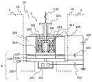
- FIG. 2 is a side sectional view of the accelerator of the present embodiment
- FIG. 3 is a transverse sectional view.
- the cyclotron accelerator 50 includes a main magnetic pole 1, an annular coil 2, a vacuum vessel 6, a high-frequency acceleration electrode 7, an ion source 3, a beam extraction / focusing unit 4, and an inflector 5. Is done.
- the main magnetic pole 1 is a pair of magnetic bodies installed so as to face each other, and is made of, for example, iron.
- the main magnetic pole 1 is provided with a convex magnetic pole 10 between the opposing magnetic poles so as to generate a circular orbit 9 of the beam, and an isochronous magnetic field is generated therebetween.
- the magnetic pole B0 is generated by the convex magnetic pole 10, and the focusing force of the circulating ion beam is increased, contributing to stable circulation.
- Opposing upper and lower surfaces between the magnetic pole gaps where the magnetic field B0 is generated are symmetrical.
- the vacuum vessel 6 is sandwiched between the main poles 1 and forms a single vacuum vessel as a whole and constitutes a magnetic circuit.
- the vacuum vessel 6 is a nonmagnetic material.
- the annular coil 2 is installed on the atmosphere side from the vacuum vessel 6 and generates a magnetic field between the pair of upper and lower main magnetic poles 1.
- the annular coil 2 can generate a magnetic field in the same manner whether it is a coil made of a normal conducting material or a coil made of a superconducting material.
- the annular coil 2 may be installed in the vacuum vessel 6 and is not particularly defined.
- a depression 1B is formed on the outer peripheral surface 1A side opposite to the surface of the main magnetic pole 1 facing the other main magnetic pole 1, and the ion source 3 and the beam extraction and focusing section 4 are formed. Is disposed inside the recess 1B. That is, the main components constituting the ion source 3 and the beam extraction and focusing unit 4 are located inside the main magnetic pole 1 from the outer peripheral surface 1A and outside the convex magnetic pole 10 when the main magnetic pole 1 is viewed from the vertical cross section. Is arranged. Ions generated by the beam extraction and focusing unit 4 are extracted from the ion source 3. Details of the ion source 3 and the beam extraction focusing unit 4 will be described later.
- the ion source 3 and the beam extraction and focusing unit 4 can be restrained from beam divergence by arranging them as close to the orbit 9 as possible, no other means for shaping the beam is required and the number of components is reduced. Can do.
- the vertical distance (mainly the convex magnetic pole 10) from the beam extraction unit 120 (see FIG. 4) of the beam extraction and focusing unit 4 to the inflector 5 is obtained.
- a set of focusing lenses 200 (see FIG. 4) is arranged according to the gap).
- the converging lens 200 need not be provided when the vertical distance from the beam extraction unit 120 (see FIG. 4) to the inflector 5 is sufficiently small. Often it is sufficient, but two or more can be provided.
- the ion source 3 and the beam extraction / condensing unit 4 can be arranged so as to be accommodated on the inner peripheral surface side of the main magnetic pole 1 in the depression provided in the lower main magnetic pole 1.
- the ion beam extracted by the beam extraction and focusing section 4 is deflected from the vertical to the horizontal direction by the inflector 5 arranged at the center of the orbit 9.
- the inflector 5 is a device that deflects an ion beam using an electric field so as not to disturb the main magnetic field B0.
- the ion beam deflected in the horizontal direction by the inflector 5 is accelerated by the high frequency acceleration electrode 7 and accelerated while drawing a spiral orbit 9 by the action of the magnetic field of the convex magnetic pole 10 and the electric field of the high frequency acceleration electrode 7. Is extracted from the orbit 9 and output to the outside.
- FIG. 4 is a diagram showing details of the ion source 3 and the beam extraction and focusing unit 4 of FIG.
- the ion source 3 is a microwave ion source using a microwave 130 for plasma generation, and includes a waveguide 101, a magnetic path 103, a coil 102, a discharge chamber 105, an introduction window 109, and an extraction electrode 110. , Flange 111 and insulator 104.
- the ion source 3 is disposed on the inner side of the recess 1B formed on the outer peripheral surface 1A side of the main magnetic pole 1 as described above.
- the discharge chamber 105 and the portion of the magnetic path 103 that shields the discharge chamber 105 may be disposed inside the main magnetic pole 1. Is not necessarily arranged inside the main pole 1, but it is desirable that other configurations are also arranged inside the main pole 1.
- the beam extraction focusing unit 4 includes a beam extraction unit 120 including a deceleration electrode 107, an insulator 106, and a ground electrode 108, and a focusing lens 200 including a lens electrode 201 and an exit hole 202.
- the microwave 130 is introduced into the vacuum discharge chamber 105 from the waveguide 101 through the introduction window 109, and the source gas is introduced from the gas supply source (not shown), and the introduced gas is converted into the microwave.
- Plasma is generated by being ionized by an electric field and a magnetic field generated by the coil 102.
- the waveguide 101 is a tube that supplies a microwave supplied from a microwave transmission source (not shown) to the inside of the ion source 3, and is made of iron.
- the waveguide 101 may be aluminum or copper, but is preferably made of iron because it is connected to the ion source 3 disposed inside the main magnetic pole 1.
- the frequency of the microwave 130 is, for example, 2.45 GHz (GHz).
- the introduction window 109 is made of an insulating material having a low dielectric constant so as to reduce the reflection of the microwave 130, and is made of, for example, quartz, boron nitride (BN), aluminum nitride, or the like.
- the discharge chamber 105 is made of a non-magnetic metallic material, and the inner peripheral side is a vacuum where plasma is generated.
- the coil 102 is disposed around the discharge chamber 105, and a magnetic path 103 is formed so as to surround the coil 102.
- the magnetic path 103 is a magnetic body shaped to cover the discharge chamber 105 and is made of, for example, iron. This magnetic path 103 prevents the magnetic field leaking from the main pole 1 from affecting the discharge chamber 105.
- the coil 102 can be adjusted independently, and the magnetic field generated in the discharge chamber 105 is adjusted. Although two coils 102 are used in FIG. 4, a magnetic field can be generated with one or three coils. In the case of one, the magnetic field distribution in the discharge chamber 105 can be adjusted by appropriately forming the shape of the magnetic path 103. The coil 102 can be replaced with a permanent magnet.
- FIG. 5 shows a two-dimensional magnetic field analysis result when a space for installing the ion source 3 is provided in the main magnetic pole 1 and the magnetic path 103 and the coil 102 are installed therein.
- the current value of the annular coil 2 was determined and analyzed so that a magnetic field of about 1.3 Tesla (T) was generated in the gap between the magnetic poles of the main magnetic pole 1.
- FIG. 6 shows the magnetic field distribution at the position of the central portion 160 shown in FIG.
- the horizontal axis indicates the vertical position of the central portion 160, and the vertical axis indicates the vertical magnetic field strength at that position.
- the insulator 104 insulates and supports the waveguide 101, the magnetic path 103, the coil 102, the discharge chamber 105, the introduction window 109, and the extraction electrode 110 in the ion source 3.
- the insulator 104 is not particularly limited as long as it is an insulating material.
- the extraction electrode 110 is an electrode disposed at the lower part of the discharge chamber 105 and is a magnetic material. By making the extraction electrode 110 magnetic, the magnetic field distribution in the discharge chamber 105 can be easily made effective for plasma generation.
- a positive voltage for example, 30 to 60 kilovolts (kV) is applied to the flange 111 of the ion source 3 by the extraction power supply 300, and a negative voltage, for example, ⁇ 2 to ⁇ 10 kilovolts (kV) is applied to the deceleration electrode 107 by the deceleration power supply 301.
- kV kilovolts
- a negative voltage for example, ⁇ 2 to ⁇ 10 kilovolts (kV) is applied to the deceleration electrode 107 by the deceleration power supply 301.
- the deceleration electrode 107 is disposed below the magnetic path 103, the coil 102, the discharge chamber 105 and the like that are insulated and supported by the insulator 104.
- the deceleration electrode 107 and the like are fixed to the ground electrode 108 by the insulator 106, and further, the main magnetic pole. 1 is fixed.
- a focusing lens (beam focusing portion) 200 including a lens electrode 201 and an exit hole 202 is attached to the ground electrode 108 in the beam extraction direction.
- the focusing lens 200 focuses the ion beam extracted from the ion source 3.
- the beam extraction focusing unit 4 is formed by integrating the focusing lens 200, the ground electrode 108, the deceleration electrode 107, and the like.
- a voltage is applied to the lens electrode 201 by a lens power source 302.
- the voltage is a positive value that does not exceed the voltage of the extraction power supply 300.
- the ion beam extracted from the ion source 3 is focused by a focusing lens 200 having a lens electrode 201 and taken out from an exit hole 202, and then the beam is projected between the convex magnetic poles 10 facing the main magnetic pole 1 by the inflector 5. Introduced into the gap.
- the beam can be focused before the ion beam extracted from the ion source 3 diverges, so that the voltage of the lens power supply 302 is kept low. Can also reduce the capacity of the power supply.
- the above-described particle beam irradiation apparatus 100 includes the accelerator 50 and the irradiation apparatus 54 that irradiates the ion beam emitted from the accelerator 50.
- the accelerator 50 generates an ion source 3 having at least a discharge chamber 105, a coil 102, and a magnetic path 103, a high-frequency acceleration electrode 7 for accelerating an ion beam extracted from the ion source 3, and a beam orbit 9. And a pair of main magnetic poles 1 disposed so as to face each other.
- the main magnetic pole 1 has a recess 1B on the surface on the outer peripheral surface 1A side opposite to the surface facing the other main magnetic pole 1, and the discharge chamber 105 and the ion source 3
- the magnetic path 103 is disposed inside the outer peripheral surface 1A of the main magnetic pole 1 when the main magnetic pole 1 is viewed from the vertical cross section, that is, is disposed in the recess 1B of the main magnetic pole 1.
- the main configuration of the ion source 3 is arranged in the recess 1B on the inner side of the outer peripheral surface 1A of the main magnetic pole 1. Therefore, the beam line after extraction from the ion source 3 can be greatly shortened compared to the conventional external ion source type as described in Patent Document 1, although it is an external ion source type, so that it is complicated and large. It is possible to provide a small accelerator capable of reducing the number of components without using a simple device. Moreover, since it is an external ion source type, the effect that the access at the time of a maintenance, replacement
- the ion source 3 has the magnetic path 103 and the discharge chamber 105 and the magnetic path 103 are disposed in the recess 1B on the inner side of the outer peripheral surface 1A of the main magnetic pole 1, the ion source is provided in the main magnetic pole 1. Even when 3 is installed, the influence of the leakage magnetic field of the main magnetic pole 1 can be blocked. Therefore, it is possible to prevent a problem that has been found by the inventor's examination that the ion source cannot be sufficiently generated simply by disposing the ion source on the inner side of the outer peripheral surface 1A of the main magnetic pole 1.
- the main magnetic pole 1 has a convex magnetic pole 10, and since the discharge chamber 105 and the magnetic path 103 in the ion source 3 are arranged outside the convex magnetic pole 10, it is difficult to access during maintenance such as replacement.
- the arrangement of the ion source of the external ion source type that is easy to access without the arrangement close to the internal ion source type is more easily obtained, and the effect that the maintenance is easy while shortening the beam line is more reliably obtained. be able to.
- the beam can be focused even if the beam diverges after the beam is extracted from the ion source 3.
- the ion source 3 is a microwave ion source, it can be a long-life ion source, and further improvement in maintainability such as reduction in replacement frequency can be achieved.
- the waveguide 101 is further connected to the ion source 3 and the waveguide 101 is made of iron, the magnetic field generated by the coil 102 can be concentrated in the discharge chamber 105 and the main magnetic pole can be concentrated. 1 can further suppress the leakage magnetic field from entering the inside of the discharge chamber 105, and the ion generation efficiency in the ion source 3 can be improved.
- a synchrocyclotron accelerator that uses a magnetic field that is not an isochronous magnetic field can be used instead of the cyclotron accelerator that uses an isochronous magnetic field as described above.
- the synchrocyclotron accelerator is a type of accelerator that is an improvement of the cyclotron. It accelerates repeatedly by applying a high-frequency electric field to charged particles that move circularly between large magnetic poles. At high speed, the mass of the accelerated particle increases due to relativistic effects, and the period of the circular motion of the charged particle in the magnetic field increases in proportion to the mass. The shift of the period from the high frequency voltage caused by this is removed by modulating the frequency.
- the ion source 3 and the beam extraction / focusing section 4 can be arranged in the main magnetic pole 1 and the same effect can be obtained.
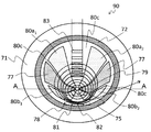
- FIG. 7 is a diagram showing a cross section of the accelerator
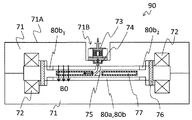
- FIG. 8 is a diagram showing a cross section AA of FIG.
- the accelerator 90 includes an ion source 73, a high-frequency acceleration electrode 77, a main magnetic pole 71, a local magnetic field generator 83, a vacuum vessel 76, and an annular coil 72. And a take-out septum 81.
- a high-frequency acceleration electrode 77 having a hollow inside is disposed symmetrically on the concave magnetic pole 80c so that a high-frequency power is applied from the outside by a high-frequency power source. Using the electric field generated by the high frequency, the high frequency acceleration electrode 77 accelerates the ion beam extracted from the ion source 73.
- the vacuum vessel 76 is arranged so as to be sandwiched between the main magnetic poles 71, and forms a single vacuum vessel as a whole and forms a main magnetic field B0 in the magnetic pole gap by forming a magnetic circuit.
- the vacuum container 76 is a nonmagnetic material.
- the annular coil 72 is installed on the atmosphere side of the vacuum vessel 76 and is a coil for causing the main magnetic pole 71 to generate the main magnetic field B0 in the magnetic pole gap between the main magnetic poles 71.
- the annular coil 72 may be a coil made of a normal conducting material or a coil made of a superconducting material.
- the main magnetic pole 71 has convex magnetic poles 80a 1 , 80a 2 , 80b 1 , 80b 2 and a concave magnetic pole 80c.
- the main magnetic pole 71 has a convex magnetic pole 80a 1 and a convex magnetic pole 80a. 2 and are symmetrical, and the convex pole 80b 1 and the convex pole 80b 2 has a structure symmetrical.
- the convex pole 80a 1 and the convex pole 80b 1 and is vertically asymmetrical
- the convex pole 80a 2 and the convex pole 80b 2 has a structure Asymmetric.
- the circulating frequency of the ion beam is, for example, 19.82 megahertz (MHz), and the main magnetic pole 71 is set to generate an isochronous magnetic field that makes one round at the same time regardless of the energy.
- the magnetic field acting on the beam along the beam trajectory is formed by the convex magnetic poles 80a 1 , 80a 2 , 80b 1, and 80b 2 so as to be a low magnetic field in the concave portion and a high magnetic field in the convex portion.
- the shape and height of the convex magnetic poles 80a 1 , 80a 2 , 80b 1 , 80b 2 are set to such an orientation and intensity as to suppress the divergence of the ion beam in the vertical direction and the circumferential direction.
- the main magnetic pole 71 is a magnetic material such as iron.
- the surface of the main magnetic pole 71 that faces the magnetic pole gap is symmetrical.
- the center of the magnetic pole formed by the convex magnetic poles 80a 1 , 80a 2 , 80b 1 , 80b 2 , and the concave magnetic pole 80c is located at a position biased from the center of the main magnetic pole 71 to the beam extraction position 82, and the ion source 73 is arranged in the vicinity thereof.
- the main magnetic pole 71 Due to such a biased arrangement structure, the main magnetic pole 71 generates a trajectory aggregation region 78 in the circular trajectory 79.
- convex magnetic poles 80a 1 , 80a 2 , 80b 1 , 80b 2 are used, but there is no limitation as long as the number is two or more.
- the convex magnetic poles 80a 1 , 80a 2 , 80b 1 , 80b 2 are provided with trim coils for fine adjustment of the magnetic field so that the isochronism and the stability of the betatron oscillation are ensured. It is also possible to adjust.
- the “isochronous magnetic field” in the present invention means that the ion beam makes one round even if the energy of the accelerated ion beam increases and the radius of the beam orbit around the ion beam increases. It means a magnetic field that does not change time.
- the “circular orbit” means a plurality of annular orbits until ions emitted from the ion source 73 are extracted from the extraction position 82.
- the ion source 73 is also formed in a recess 71B formed in the outer peripheral surface 71A of the main magnetic pole 71 when the main magnetic pole 71 is viewed from the vertical cross section, and in the convex magnetic poles 80a 1 , 80a 2 , 80b. 1 and 80b 2 are arranged outside.
- the discharge chamber and the portion of the magnetic path that shields the discharge chamber need only be disposed inside the main magnetic pole 71, and other configurations are not necessarily disposed inside the main magnetic pole 71. There is no need to be done.
- Accelerator 90 configured as described above operates as follows.
- the ion beam extracted from the ion source 73 by the beam extraction and converging unit 74 is deflected from the vertical to the horizontal direction by the inflector 75 disposed at the center of the circular orbit 79, and the convex magnetic poles 80a 1 , 80a 2 , 80b 1 , 80b 2 , Helical motion is performed by the main magnetic field B0 formed by the concave magnetic pole 80c.
- Each time it passes through the high-frequency acceleration electrode 77 during the spiral motion it is accelerated by the electric field generated at the high-frequency acceleration electrode 77, the energy is increased, and the rotation radius is increased to move around the vacuum vessel 76.
- the shape and height of the convex magnetic poles 80a 1 , 80a 2 , 80b 1 , 80b 2 are set to such an orientation and intensity that suppress the divergence of the beam in the vertical direction and the circumferential direction, and the ion beam
- the energy is set to make one round in the same time.
- the magnetic field acting on the beam along the beam trajectory is a low magnetic field in the concave portion and a high magnetic field in the convex portion due to the convex magnetic poles 80a 1 , 80a 2 , 80b 1 , and 80b 2 .
- the strength of the magnetic field along the beam trajectory is added, and the average value of the magnetic field along the trajectory is proportional to the relativistic gamma factor ( ⁇ factor) of the beam.
- the betatron oscillation is stably performed in the direction perpendicular to the orbital plane and the orbital plane of the beam.
- the orbiting beam is deflected by the local magnetic field generated by the local magnetic field generator 83 that has reached the extraction energy.
- the orbiting beam deviates from the orbit, moves to the extraction position 82, and is guided out of the accelerator 90 by the extraction septum 81.
- the direction of the local magnetic field is determined by the energy in the same or opposite direction as the main magnetic field B0. Since the orbiting ion beam trajectory is gathered at the take-out position 82, deflection and take-out toward the take-out position 82 can be performed with a smaller local magnetic field compared to the trajectory that has not been gathered.
- the main magnetic pole 71 is formed so as to generate the trajectory aggregation region 78 in the circular trajectory 79, the circulating ion beam trajectory is aggregated at the extraction position 82.
- the beam can be deflected to the beam extraction position 82 with a smaller local magnetic field, and the extraction is very easy.
- a predetermined magnetic field can be obtained by using a magnetic field generated by the local magnetic field generation unit 83.
- the ion beam of energy can be deflected stably and easily toward the beam extraction position 82 on the trajectory aggregation region 78 side.
- the ion source is not limited to the microwave ion source.
- the present invention can be applied to a direct current type or high frequency type ion source as long as a magnetic path is provided so as to shield the discharge chamber.
- Local magnetic field generator 100 Particle beam irradiation device 101 ... Waveguide 102 ... Coil 103 ... Magnetic path 104 ... Insulator 105 ... Discharge chamber 106 ... Insulator 107 ... Deceleration electrode 108 ... Ground electrode 109 ... Introduction window 110 ... Extraction electrode 111 ... Flange 120 ... Beam extraction part 130 ... My B wave 160 ... center 200 ... converging lens (beam focusing portion) 201 ... Lens electrode 202 ... Outlet hole 300 ... Drawer power supply 301 ... Deceleration power supply 302 ... Lens power supply
Abstract
In this accelerator 50, a main magnetic pole 1 has a recess 1B in the surface that is on the side of an outer peripheral surface 1A which faces away from the surface opposing another main magnetic pole 1. In an ion source 3, a discharge chamber 105 and a magnetic path 103 are disposed more inward than the outer peripheral surface 1A of the main magnetic pole 1 when the main magnetic pole 1 is viewed from a vertical direction cross section. In other words, the discharge chamber and the magnetic path are disposed in the recess 1B of the main magnetic pole 1. In this manner, a beam line can be shortened, providing an external ion source type accelerator that does not use a large-scale device, and a particle beam irradiation device equipped therewith.
Description
本発明は、陽子や炭素等のイオンを加速する加速器とそれを備えた粒子線照射装置に関する。
The present invention relates to an accelerator for accelerating ions such as protons and carbon and a particle beam irradiation apparatus including the accelerator.
サイクロトロン型加速器において外部に設置されたイオン源を用いることが特許文献1に記載されている。この特許文献1には、外部イオン源からサイクロトロンへイオンビームが入射するまでの機器構成が記載されている。
Patent Document 1 describes the use of an ion source installed outside in a cyclotron accelerator. This Patent Document 1 describes a device configuration from when an ion beam is incident on a cyclotron from an external ion source.
上述した特許文献1には、外部からイオンビームを入射する外部イオン源型入射システムを持つサイクロトロン型加速器が記載されている。しかし、この特許文献1に記載されたイオン源の配置ではビームライン上に多くのレンズ機構が必要である。このため、装置が複雑かつ大がかりとなる、との問題があった。
Patent Document 1 described above describes a cyclotron accelerator having an external ion source type incident system for injecting an ion beam from the outside. However, the arrangement of the ion source described in Patent Document 1 requires many lens mechanisms on the beam line. For this reason, there has been a problem that the apparatus becomes complicated and large.
本発明の目的は、ビームラインを短縮することができ、大がかりな装置を用いることのない外部イオン源型の加速器とそれを備えた粒子線照射装置を提供することにある。
An object of the present invention is to provide an external ion source type accelerator that can shorten a beam line and does not use a large-scale apparatus, and a particle beam irradiation apparatus including the accelerator.
上記課題を解決するために、例えば特許請求の範囲に記載の構成を採用する。
In order to solve the above problems, for example, the configuration described in the claims is adopted.
本発明は、上記課題を解決する手段を複数含んでいるが、その一例を挙げるならば、少なくとも放電室、コイルおよび磁路を有するイオン源と、前記イオン源から引き出されたイオンビームを加速する高周波加速電極と、前記イオンビームの周回軌道を発生させるように形成された、磁場を発生させる磁極と、を備え、前記イオン源のうち、前記放電室および前記磁路が、前記磁極を鉛直方向断面から見たときに前記磁極の外周面より内側に配置されたことを特徴とする。
The present invention includes a plurality of means for solving the above-described problems. For example, an ion source having at least a discharge chamber, a coil, and a magnetic path, and an ion beam extracted from the ion source are accelerated. A high-frequency accelerating electrode; and a magnetic pole for generating a magnetic field formed so as to generate a circular orbit of the ion beam, wherein the discharge chamber and the magnetic path of the ion source have the magnetic pole in a vertical direction. When viewed from a cross-section, the magnetic pole is arranged inside the outer peripheral surface of the magnetic pole.
また、他の一例をあげるならば、少なくとも放電室、コイルおよび磁路を有するイオン源と、前記イオン源から引き出されたイオンビームを加速する高周波加速電極と、対向するように設置され、磁場を間に形成する一対の磁極と、を備え、前記磁極は、もう一つの磁極と対向する面の逆の面に窪みを有しており、前記イオン源のうち前記放電室および前記磁路が前記磁極の前記窪みの中に配置されたことを特徴とする。
As another example, an ion source having at least a discharge chamber, a coil, and a magnetic path, and a high-frequency acceleration electrode for accelerating an ion beam extracted from the ion source are disposed so as to face each other, and a magnetic field is generated. A pair of magnetic poles formed in between, the magnetic pole has a depression on the opposite side of the surface facing the other magnetic pole, and the discharge chamber and the magnetic path of the ion source are the It is arranged in the recess of the magnetic pole.
本発明によれば、ビームラインを短縮することができ、大がかりな装置を用いることのない外部イオン源型の加速器とそれを備えた粒子線照射装置が提供される。
According to the present invention, an external ion source type accelerator that can shorten the beam line and does not use a large-scale apparatus and a particle beam irradiation apparatus including the accelerator are provided.
以下に本発明の加速器および粒子線照射装置の実施例を、図面を用いて説明する。
Embodiments of an accelerator and a particle beam irradiation apparatus according to the present invention will be described below with reference to the drawings.
<実施例1>
本発明の実施例1の加速器および粒子線照射装置を、図1乃至図6を用いて説明する。最初に、粒子線照射装置の全体構成および関連する装置の構成について図1を用いて説明する。図1は、本実施例の粒子線照射装置の全体構成を示す図である。 <Example 1>
An accelerator and a particle beam irradiation apparatus according to a first embodiment of the present invention will be described with reference to FIGS. Initially, the whole structure of a particle beam irradiation apparatus and the structure of a related apparatus are demonstrated using FIG. FIG. 1 is a diagram showing the overall configuration of the particle beam irradiation apparatus of the present embodiment.
図1において、粒子線照射装置100は、サイクロトロン型の加速器50、ビーム輸送系52、照射装置54、治療台40、および制御装置56を備える。
1, the particle beam irradiation apparatus 100 includes a cyclotron accelerator 50, a beam transport system 52, an irradiation apparatus 54, a treatment table 40, and a control apparatus 56.
粒子線照射装置100では、イオン源3で発生させたイオンを加速器50で加速してイオンビームとする。加速されたイオンビームは加速器50から出射され、ビーム輸送系52により照射装置54まで輸送される。輸送されたイオンビームは照射装置54で患部形状に合致するように整形され、治療台40に横になった患者45の標的に対して所定量照射される。
In the particle beam irradiation apparatus 100, ions generated by the ion source 3 are accelerated by an accelerator 50 to be an ion beam. The accelerated ion beam is emitted from the accelerator 50 and transported to the irradiation device 54 by the beam transport system 52. The transported ion beam is shaped by the irradiation device 54 so as to match the shape of the affected area, and a predetermined amount is irradiated to the target of the patient 45 lying on the treatment table 40.
これら加速器50をはじめとした粒子線照射装置100内の各装置,機器の動作は、制御装置56によって制御される。
The operation of each device and equipment in the particle beam irradiation apparatus 100 including the accelerator 50 is controlled by the control device 56.
次に加速器50の構造について図2乃至図6を用いて説明する。図2は本実施例の加速器の側面の断面図で、図3は横断面図である。
Next, the structure of the accelerator 50 will be described with reference to FIGS. FIG. 2 is a side sectional view of the accelerator of the present embodiment, and FIG. 3 is a transverse sectional view.
図2および図3に示すように、サイクロトロン型の加速器50は、主磁極1、円環状コイル2、真空容器6、高周波加速電極7、イオン源3、ビーム引き出し集束部4、インフレクター5によって構成される。
As shown in FIGS. 2 and 3, the cyclotron accelerator 50 includes a main magnetic pole 1, an annular coil 2, a vacuum vessel 6, a high-frequency acceleration electrode 7, an ion source 3, a beam extraction / focusing unit 4, and an inflector 5. Is done.
主磁極1は、対向するように設置された一対の磁性体であり、例えば鉄などからなる。主磁極1には、ビームの周回軌道9を発生させるように向かい合う磁極間に凸磁極10が設けられており、等時性磁場をその間に発生させる。凸磁極10によって磁場B0を発生させるとともに、周回するイオンビームの集束力を増加させ、安定周回に寄与する。磁場B0が発生する磁極ギャップ間の対向する上下面は対称形状である。
The main magnetic pole 1 is a pair of magnetic bodies installed so as to face each other, and is made of, for example, iron. The main magnetic pole 1 is provided with a convex magnetic pole 10 between the opposing magnetic poles so as to generate a circular orbit 9 of the beam, and an isochronous magnetic field is generated therebetween. The magnetic pole B0 is generated by the convex magnetic pole 10, and the focusing force of the circulating ion beam is increased, contributing to stable circulation. Opposing upper and lower surfaces between the magnetic pole gaps where the magnetic field B0 is generated are symmetrical.
真空容器6は主磁極1によって挟まれており、全体としてひとつの真空容器を形成するとともに磁気回路を構成する。真空容器6は非磁性体である。
The vacuum vessel 6 is sandwiched between the main poles 1 and forms a single vacuum vessel as a whole and constitutes a magnetic circuit. The vacuum vessel 6 is a nonmagnetic material.
円環状コイル2は真空容器6より大気側に設置されており、上下一対の主磁極1間に磁場を発生させる。円環状コイル2は常電導材料によるコイルでも超電導材料によるコイルでも同様に磁場を発生可能である。なお、円環状コイル2は真空容器6内に設置してもよく、特に規定されるものではない。
The annular coil 2 is installed on the atmosphere side from the vacuum vessel 6 and generates a magnetic field between the pair of upper and lower main magnetic poles 1. The annular coil 2 can generate a magnetic field in the same manner whether it is a coil made of a normal conducting material or a coil made of a superconducting material. The annular coil 2 may be installed in the vacuum vessel 6 and is not particularly defined.
図2および図3に示すように、主磁極1のもう一つの主磁極1と対向する面とは逆の外周面1A側に窪み1Bが形成されており、イオン源3およびビーム引き出し集束部4がその窪み1Bの中側に配置されている。すなわち、イオン源3を構成する主な構成要素やビーム引き出し集束部4が、主磁極1を鉛直方向断面から見たときに外周面1Aより主磁極1の内側であり、かつ凸磁極10より外側に配置されている。ビーム引き出し集束部4によって生成されたイオンをイオン源3から引き出している。イオン源3やビーム引き出し集束部4の詳細については後述する。
As shown in FIGS. 2 and 3, a depression 1B is formed on the outer peripheral surface 1A side opposite to the surface of the main magnetic pole 1 facing the other main magnetic pole 1, and the ion source 3 and the beam extraction and focusing section 4 are formed. Is disposed inside the recess 1B. That is, the main components constituting the ion source 3 and the beam extraction and focusing unit 4 are located inside the main magnetic pole 1 from the outer peripheral surface 1A and outside the convex magnetic pole 10 when the main magnetic pole 1 is viewed from the vertical cross section. Is arranged. Ions generated by the beam extraction and focusing unit 4 are extracted from the ion source 3. Details of the ion source 3 and the beam extraction focusing unit 4 will be described later.
イオン源3及びビーム引き出し集束部4は、できるだけ周回軌道9に近い位置に配置することでビームの発散を抑えることができるため、そのほかにビームを整形する手段が不要となり、構成機器を低減することができる。
Since the ion source 3 and the beam extraction and focusing unit 4 can be restrained from beam divergence by arranging them as close to the orbit 9 as possible, no other means for shaping the beam is required and the number of components is reduced. Can do.
なお、イオン源3より引き出された直後のイオンビームは発散ビームとなるが、ビーム引き出し集束部4のビーム引き出し部120(図4参照)からインフレクター5までの鉛直方向距離(主に凸磁極10のギャップ)に応じて一組の集束レンズ200(図4参照)を配置する。このビーム引き出し集束部4のうち集束レンズ200については、ビーム引き出し部120(図4参照)からインフレクター5までの鉛直方向距離が十分に小さいときは設ける必要はなく、設ける場合も一つあれば十分であることが多いが、2つ以上設けることもできる。
Although the ion beam immediately after being extracted from the ion source 3 becomes a diverging beam, the vertical distance (mainly the convex magnetic pole 10) from the beam extraction unit 120 (see FIG. 4) of the beam extraction and focusing unit 4 to the inflector 5 is obtained. A set of focusing lenses 200 (see FIG. 4) is arranged according to the gap). Of the beam extraction / condensing unit 4, the converging lens 200 need not be provided when the vertical distance from the beam extraction unit 120 (see FIG. 4) to the inflector 5 is sufficiently small. Often it is sufficient, but two or more can be provided.
なお、イオン源3及びビーム引き出し集束部4は、下側の主磁極1に設けられた窪みの主磁極1の内周面側に収まるように配置することもできる。
It should be noted that the ion source 3 and the beam extraction / condensing unit 4 can be arranged so as to be accommodated on the inner peripheral surface side of the main magnetic pole 1 in the depression provided in the lower main magnetic pole 1.
ビーム引き出し集束部4によって引き出されたイオンビームは周回軌道9の中心に配置したインフレクター5により垂直から水平方向に偏向される。インフレクター5は主磁場B0を乱さないように電場を用いてイオンビームを偏向する機器である。
The ion beam extracted by the beam extraction and focusing section 4 is deflected from the vertical to the horizontal direction by the inflector 5 arranged at the center of the orbit 9. The inflector 5 is a device that deflects an ion beam using an electric field so as not to disturb the main magnetic field B0.
インフレクター5によって水平方向に偏向されたイオンビームは、高周波加速電極7によって加速され、凸磁極10の磁場および高周波加速電極7の電場の作用によって螺旋状の周回軌道9を描きながら加速され、十分に加速された後で周回軌道9から引き出されて外部へ出力される。
The ion beam deflected in the horizontal direction by the inflector 5 is accelerated by the high frequency acceleration electrode 7 and accelerated while drawing a spiral orbit 9 by the action of the magnetic field of the convex magnetic pole 10 and the electric field of the high frequency acceleration electrode 7. Is extracted from the orbit 9 and output to the outside.
次に図4~図6を用いて、イオン源3及びビーム引き出し集束部4の詳細を説明する。図4は図2のイオン源3及びビーム引き出し集束部4の詳細を示した図である。
Next, details of the ion source 3 and the beam extraction and focusing unit 4 will be described with reference to FIGS. FIG. 4 is a diagram showing details of the ion source 3 and the beam extraction and focusing unit 4 of FIG.
図4に示すように、イオン源3はプラズマ生成にマイクロ波130を利用したマイクロ波イオン源であり、導波管101、磁路103、コイル102、放電室105、導入窓109、引き出し電極110、フランジ111、絶縁物104で構成される。イオン源3は、上述のように主磁極1の外周面1A側に形成された窪み1Bの中側に配置されている。
As shown in FIG. 4, the ion source 3 is a microwave ion source using a microwave 130 for plasma generation, and includes a waveguide 101, a magnetic path 103, a coil 102, a discharge chamber 105, an introduction window 109, and an extraction electrode 110. , Flange 111 and insulator 104. The ion source 3 is disposed on the inner side of the recess 1B formed on the outer peripheral surface 1A side of the main magnetic pole 1 as described above.
なお、イオン源3のうち、放電室105と、磁路103のうち放電室105をシールドする部分が、主磁極1の内部に配置されていればよく、イオン源3を構成するその他の構成については必ずしも主磁極1の内部に配置される必要はないが、その他の構成についても主磁極1の内部に配置されることが望ましい。
Of the ion source 3, the discharge chamber 105 and the portion of the magnetic path 103 that shields the discharge chamber 105 may be disposed inside the main magnetic pole 1. Is not necessarily arranged inside the main pole 1, but it is desirable that other configurations are also arranged inside the main pole 1.
ビーム引き出し集束部4は、減速電極107、絶縁物106、接地電極108で構成されたビーム引き出し部120と、レンズ電極201および出口孔202で構成された集束レンズ200と、から構成される。
The beam extraction focusing unit 4 includes a beam extraction unit 120 including a deceleration electrode 107, an insulator 106, and a ground electrode 108, and a focusing lens 200 including a lens electrode 201 and an exit hole 202.
イオン源3では、導波管101から導入窓109を通してマイクロ波130を真空となる放電室105に導入するとともに、ガス供給源(図示省略)から原料ガスを導入して、導入したガスをマイクロ波電場とコイル102による磁場によってイオン化させることでプラズマを生成する。
In the ion source 3, the microwave 130 is introduced into the vacuum discharge chamber 105 from the waveguide 101 through the introduction window 109, and the source gas is introduced from the gas supply source (not shown), and the introduced gas is converted into the microwave. Plasma is generated by being ionized by an electric field and a magnetic field generated by the coil 102.
導波管101はマイクロ波発信源(図示省略)から供給されるマイクロ波をイオン源3の内部に供給する管であり、鉄製である。なお導波管101はアルミニウムや銅であってもよいが、主磁極1の内部に配置されたイオン源3に接続されるため、鉄製が好適である。
The waveguide 101 is a tube that supplies a microwave supplied from a microwave transmission source (not shown) to the inside of the ion source 3, and is made of iron. The waveguide 101 may be aluminum or copper, but is preferably made of iron because it is connected to the ion source 3 disposed inside the main magnetic pole 1.
マイクロ波130の周波数は例えば2.45ギガヘルツ(GHz)などである。
The frequency of the microwave 130 is, for example, 2.45 GHz (GHz).
導入窓109はマイクロ波130の反射が小さくなるように低誘電率の絶縁材料からなり、例えば石英やボロンナイトライド(BN)、窒化アルミなどでの材質である。
The introduction window 109 is made of an insulating material having a low dielectric constant so as to reduce the reflection of the microwave 130, and is made of, for example, quartz, boron nitride (BN), aluminum nitride, or the like.
放電室105は非磁性体の金属性の材料からなり、その内周側が真空となってプラズマが生成される箇所となる。
The discharge chamber 105 is made of a non-magnetic metallic material, and the inner peripheral side is a vacuum where plasma is generated.
コイル102は放電室105の周囲に配置されており、そのコイル102を囲むように磁路103が形成されている。
The coil 102 is disposed around the discharge chamber 105, and a magnetic path 103 is formed so as to surround the coil 102.
磁路103は放電室105を覆うような形状をした磁性体であり、例えば鉄などからなる。この磁路103により、主磁極1から漏洩する磁場が放電室105に影響することを防止する。
The magnetic path 103 is a magnetic body shaped to cover the discharge chamber 105 and is made of, for example, iron. This magnetic path 103 prevents the magnetic field leaking from the main pole 1 from affecting the discharge chamber 105.
コイル102は独立に調整可能とし、放電室105内に発生する磁場を調整する。図4ではコイル102を2個使用しているが、1個あるいは3個でも磁場の発生は可能である。1個の場合は磁路103の形状を適切に形成することで放電室105内の磁場分布を調整可能である。このコイル102は永久磁石に置き換えることが可能である。
The coil 102 can be adjusted independently, and the magnetic field generated in the discharge chamber 105 is adjusted. Although two coils 102 are used in FIG. 4, a magnetic field can be generated with one or three coils. In the case of one, the magnetic field distribution in the discharge chamber 105 can be adjusted by appropriately forming the shape of the magnetic path 103. The coil 102 can be replaced with a permanent magnet.
図5は主磁極1にイオン源3設置用の空間を設け、そこに磁路103とコイル102を設置したときの2次元磁場解析結果である。主磁極1の磁極間ギャップには約1.3テスラ(T)の磁場が発生するように円環状コイル2の電流値を決定して解析した。
FIG. 5 shows a two-dimensional magnetic field analysis result when a space for installing the ion source 3 is provided in the main magnetic pole 1 and the magnetic path 103 and the coil 102 are installed therein. The current value of the annular coil 2 was determined and analyzed so that a magnetic field of about 1.3 Tesla (T) was generated in the gap between the magnetic poles of the main magnetic pole 1.
この図5に示すように、主磁極1から漏洩する磁場は磁路103に流れ込むため、放電室105内への漏洩磁場の影響を低下できることが分かった。このため、コイル102によって生成される磁場が放電室105側に十分に形成されることが分かった。また、主磁極1から漏洩する磁場は導波管101にも流れ込むことから、導波管101の材質を適宜選択することによって放電室105内への漏洩磁場の影響をより低下できることも分かった。
As shown in FIG. 5, since the magnetic field leaking from the main pole 1 flows into the magnetic path 103, it was found that the influence of the leaking magnetic field into the discharge chamber 105 can be reduced. For this reason, it has been found that the magnetic field generated by the coil 102 is sufficiently formed on the discharge chamber 105 side. Further, since the magnetic field leaking from the main magnetic pole 1 also flows into the waveguide 101, it has been found that the influence of the leakage magnetic field into the discharge chamber 105 can be further reduced by appropriately selecting the material of the waveguide 101.
図6に、図5に示す中心部160位置での磁場分布を示す。横軸が中心部160の縦位置を示し、縦軸がその位置での縦方向磁場強度を示す。
FIG. 6 shows the magnetic field distribution at the position of the central portion 160 shown in FIG. The horizontal axis indicates the vertical position of the central portion 160, and the vertical axis indicates the vertical magnetic field strength at that position.
図6に示すように、イオン源3が主磁極1に配置されていない場合150は、数百ガウスの漏れ磁場がある。これに対し、磁路103を有するイオン源3がある場合151では、放電室105内の磁場が0に近くなる。さらに磁路103を有するイオン源3においてコイル102によりプラズマ生成用の磁場を発生させた場合152では、プラズマ生成に必要なサイクロトロン共鳴磁場強度0.0875テスラ以上の傾斜を持った磁場が形成できることが分かる。
As shown in FIG. 6, when the ion source 3 is not arranged on the main pole 1, 150 has a leakage magnetic field of several hundred gauss. On the other hand, when there is an ion source 3 having a magnetic path 103, the magnetic field in the discharge chamber 105 becomes close to zero. Further, in the case where a magnetic field for plasma generation is generated by the coil 102 in the ion source 3 having the magnetic path 103, a magnetic field having a gradient of cyclotron resonance magnetic field strength required for plasma generation of 0.0875 Tesla or more can be formed. I understand.
図4に戻って、絶縁物104は、イオン源3中の導波管101、磁路103、コイル102、放電室105、導入窓109、引き出し電極110を絶縁支持する。絶縁物104は絶縁性の材料であれば特に限定されない。
4, the insulator 104 insulates and supports the waveguide 101, the magnetic path 103, the coil 102, the discharge chamber 105, the introduction window 109, and the extraction electrode 110 in the ion source 3. The insulator 104 is not particularly limited as long as it is an insulating material.
引き出し電極110は放電室105の下部に配置された電極であり、磁性体である。引き出し電極110を磁性体にすることで、容易に放電室105内の磁場分布をプラズマ生成に有効な分布とすることができる。
The extraction electrode 110 is an electrode disposed at the lower part of the discharge chamber 105 and is a magnetic material. By making the extraction electrode 110 magnetic, the magnetic field distribution in the discharge chamber 105 can be easily made effective for plasma generation.
イオン源3のフランジ111には引き出し電源300により正の電圧、例えば30~60キロボルト(kV)を印加し、減速電極107には減速電源301により負の電圧、例えば-2~-10キロボルト(kV)を印加する。引き出し電源300および減速電源301によって発生する引き出し電極110と減速電極107間の電場によって、放電室105内に生成したプラズマからイオンビームを引き出す。
A positive voltage, for example, 30 to 60 kilovolts (kV) is applied to the flange 111 of the ion source 3 by the extraction power supply 300, and a negative voltage, for example, −2 to −10 kilovolts (kV) is applied to the deceleration electrode 107 by the deceleration power supply 301. ) Is applied. An ion beam is extracted from the plasma generated in the discharge chamber 105 by the electric field between the extraction electrode 110 and the deceleration electrode 107 generated by the extraction power source 300 and the deceleration power source 301.
減速電極107は絶縁物104によって絶縁支持された磁路103、コイル102、放電室105等の下方に配置されており、減速電極107等は絶縁物106によって接地電極108に固定され、さらに主磁極1に固定されている。
The deceleration electrode 107 is disposed below the magnetic path 103, the coil 102, the discharge chamber 105 and the like that are insulated and supported by the insulator 104. The deceleration electrode 107 and the like are fixed to the ground electrode 108 by the insulator 106, and further, the main magnetic pole. 1 is fixed.
接地電極108には、ビーム引き出し方向にレンズ電極201、出口孔202で構成される集束レンズ(ビーム集束部)200を取り付ける。集束レンズ200は、イオン源3より引き出されたイオンビームを集束させる。この集束レンズ200と接地電極108と減速電極107等とを一体構造としてビーム引き出し集束部4を形成する。
A focusing lens (beam focusing portion) 200 including a lens electrode 201 and an exit hole 202 is attached to the ground electrode 108 in the beam extraction direction. The focusing lens 200 focuses the ion beam extracted from the ion source 3. The beam extraction focusing unit 4 is formed by integrating the focusing lens 200, the ground electrode 108, the deceleration electrode 107, and the like.
レンズ電極201にはレンズ電源302によって電圧を印加する。電圧は引き出し電源300の電圧を超えない正の値である。レンズ電極201はビーム引き出し方向に複数個設置して、それぞれ独立した電圧を印加することで、さらにビームを自由に整形可能となる。電圧は独立した電源で印加しても、抵抗分割などにより1台の電源で印加してもかまわない。
A voltage is applied to the lens electrode 201 by a lens power source 302. The voltage is a positive value that does not exceed the voltage of the extraction power supply 300. By installing a plurality of lens electrodes 201 in the beam extraction direction and applying independent voltages to each other, the beam can be further shaped freely. The voltage may be applied by an independent power source or by a single power source by resistance division or the like.
イオン源3から引き出されたイオンビームは、レンズ電極201を有する集束レンズ200で集束されて出口孔202から取り出された後、インフレクター5によってビームを主磁極1の対抗する凸磁極10の間のギャップへ導入される。
The ion beam extracted from the ion source 3 is focused by a focusing lens 200 having a lens electrode 201 and taken out from an exit hole 202, and then the beam is projected between the convex magnetic poles 10 facing the main magnetic pole 1 by the inflector 5. Introduced into the gap.
一体化したビーム引き出し集束部4をイオン源3の直後に取り付けることによって、イオン源3から引き出されたイオンビームが発散する前にビームを集束させることができるので、レンズ電源302の電圧を低く抑えることができ、電源の容量低減にもつながる。
By attaching the integrated beam extraction and focusing unit 4 immediately after the ion source 3, the beam can be focused before the ion beam extracted from the ion source 3 diverges, so that the voltage of the lens power supply 302 is kept low. Can also reduce the capacity of the power supply.
次に、本実施例の効果について説明する。
Next, the effect of this embodiment will be described.
上述した本発明の実施例1の粒子線照射装置100は、加速器50と、加速器50から出射されたイオンビームを照射する照射装置54と、を備えている。このうち、加速器50は、少なくとも放電室105、コイル102および磁路103を有するイオン源3と、イオン源3から引き出されたイオンビームを加速する高周波加速電極7と、ビームの周回軌道9を発生させるように対向して設置された一対の主磁極1と、を備えている。このような加速器50において、主磁極1は、もう一つの主磁極1と対向する面の逆となる外周面1A側の面に窪み1Bを有しており、イオン源3のうち放電室105および磁路103が、主磁極1を鉛直方向断面から見たときに主磁極1の外周面1Aより内側に配置、すなわち主磁極1の窪み1Bの中に配置されている。
The above-described particle beam irradiation apparatus 100 according to the first embodiment of the present invention includes the accelerator 50 and the irradiation apparatus 54 that irradiates the ion beam emitted from the accelerator 50. Among these, the accelerator 50 generates an ion source 3 having at least a discharge chamber 105, a coil 102, and a magnetic path 103, a high-frequency acceleration electrode 7 for accelerating an ion beam extracted from the ion source 3, and a beam orbit 9. And a pair of main magnetic poles 1 disposed so as to face each other. In such an accelerator 50, the main magnetic pole 1 has a recess 1B on the surface on the outer peripheral surface 1A side opposite to the surface facing the other main magnetic pole 1, and the discharge chamber 105 and the ion source 3 The magnetic path 103 is disposed inside the outer peripheral surface 1A of the main magnetic pole 1 when the main magnetic pole 1 is viewed from the vertical cross section, that is, is disposed in the recess 1B of the main magnetic pole 1.
このような構成によって、外部イオン源型のイオン源3を備えたサイクロトロン型の加速器50において、主磁極1の外周面1Aより内部側の窪み1B内にイオン源3の主な構成が配置されるため、外部イオン源型でありながら、特許文献1に記載のような従来の外部イオン源型に比べてイオン源3からの引き出し後のビームラインを大幅に短縮することができるため、複雑かつ大がかりな装置を用いることなく、構成機器数を低減することが可能な小型の加速器を提供することができる。また、外部イオン源型であるため、メンテナンスや交換などの際のアクセスも容易である、との効果も得られるものとなっている。
With such a configuration, in the cyclotron accelerator 50 including the external ion source type ion source 3, the main configuration of the ion source 3 is arranged in the recess 1B on the inner side of the outer peripheral surface 1A of the main magnetic pole 1. Therefore, the beam line after extraction from the ion source 3 can be greatly shortened compared to the conventional external ion source type as described in Patent Document 1, although it is an external ion source type, so that it is complicated and large. It is possible to provide a small accelerator capable of reducing the number of components without using a simple device. Moreover, since it is an external ion source type, the effect that the access at the time of a maintenance, replacement | exchange, etc. is also easy is acquired.
また、イオン源3が磁路103を有するものとし、また放電室105と磁路103とが主磁極1の外周面1Aより内部側の窪み1B内に配置されたため、主磁極1内にイオン源3を設置した場合でも主磁極1の漏洩磁場の影響を遮断することができる。よって、単にイオン源を主磁極1の外周面1Aより内部側に配置するだけではイオンの生成が十分にできない、という本発明者の検討によって判明した問題が生じることも防止されている。
Further, since the ion source 3 has the magnetic path 103 and the discharge chamber 105 and the magnetic path 103 are disposed in the recess 1B on the inner side of the outer peripheral surface 1A of the main magnetic pole 1, the ion source is provided in the main magnetic pole 1. Even when 3 is installed, the influence of the leakage magnetic field of the main magnetic pole 1 can be blocked. Therefore, it is possible to prevent a problem that has been found by the inventor's examination that the ion source cannot be sufficiently generated simply by disposing the ion source on the inner side of the outer peripheral surface 1A of the main magnetic pole 1.
また、主磁極1は、凸磁極10を有しており、イオン源3のうち放電室105および磁路103が、凸磁極10より外側に配置されたため、交換などのメンテナンスの際にアクセスが困難な内部イオン源型に近い配置とならずに、アクセスが容易な外部イオン源型のイオン源の配置となり、ビームラインの短縮を図りつつ、メンテナンスが容易である、との効果をより確実に得ることができる。
Further, the main magnetic pole 1 has a convex magnetic pole 10, and since the discharge chamber 105 and the magnetic path 103 in the ion source 3 are arranged outside the convex magnetic pole 10, it is difficult to access during maintenance such as replacement. The arrangement of the ion source of the external ion source type that is easy to access without the arrangement close to the internal ion source type is more easily obtained, and the effect that the maintenance is easy while shortening the beam line is more reliably obtained. be able to.
更に、イオン源3より引き出されたイオンビームを集束させる集束レンズ200を少なくとも一つ以上備えたことで、イオン源3からのビーム引き出し後にビームが発散したとしてもビームを集束させることができる。
Further, by providing at least one focusing lens 200 for focusing the ion beam extracted from the ion source 3, the beam can be focused even if the beam diverges after the beam is extracted from the ion source 3.
また、イオン源3は、マイクロ波イオン源であることにより、長寿命のイオン源とすることができ、交換頻度の低減などのメンテナンス性の更なる向上を図ることができる。
In addition, since the ion source 3 is a microwave ion source, it can be a long-life ion source, and further improvement in maintainability such as reduction in replacement frequency can be achieved.
更に、イオン源3に接続された導波管101を更に有し、導波管101が鉄製であることで、コイル102で発生させた磁場を放電室105により集中させることができるとともに、主磁極1からの漏洩磁場が放電室105内部に入り込むことをより抑制することができ、イオン源3におけるイオン生成効率の向上を図ることができる。
Furthermore, since the waveguide 101 is further connected to the ion source 3 and the waveguide 101 is made of iron, the magnetic field generated by the coil 102 can be concentrated in the discharge chamber 105 and the main magnetic pole can be concentrated. 1 can further suppress the leakage magnetic field from entering the inside of the discharge chamber 105, and the ion generation efficiency in the ion source 3 can be improved.
なお、加速器50として、上述のような等時性磁場を用いるサイクロトロン型の加速器の替わりに、等時性磁場ではない磁場を用いるシンクロサイクロトロン型の加速器を用いることができる。
As the accelerator 50, a synchrocyclotron accelerator that uses a magnetic field that is not an isochronous magnetic field can be used instead of the cyclotron accelerator that uses an isochronous magnetic field as described above.
シンクロサイクロトロン型の加速器とは、サイクロトロンを改良した加速器の一種であり、大型磁極間で円運動する荷電粒子に高周波電場を加えて繰返し加速する。また、高速では加速された粒子の質量が相対論的効果によって増加し、磁場内の荷電粒子の円運動の周期は質量に比例して増加する。これによって起こる高周波電圧との周期のずれを、周波数を変調することによって取り除いている。
The synchrocyclotron accelerator is a type of accelerator that is an improvement of the cyclotron. It accelerates repeatedly by applying a high-frequency electric field to charged particles that move circularly between large magnetic poles. At high speed, the mass of the accelerated particle increases due to relativistic effects, and the period of the circular motion of the charged particle in the magnetic field increases in proportion to the mass. The shift of the period from the high frequency voltage caused by this is removed by modulating the frequency.
シンクロサイクロトロン型の加速器も構成がサイクロトロン型の加速器と同様の構成であることからイオン源3やビーム引き出し集束部4を主磁極1内に配置することができ、同様の効果が得られる。
Since the structure of the synchrocyclotron accelerator is the same as that of the cyclotron accelerator, the ion source 3 and the beam extraction / focusing section 4 can be arranged in the main magnetic pole 1 and the same effect can be obtained.
<実施例2>
本発明の実施例2の加速器および粒子線照射装置を図7および図8を用いて説明する。 <Example 2>
An accelerator and a particle beam irradiation apparatus according toEmbodiment 2 of the present invention will be described with reference to FIGS.
本発明の実施例2の加速器および粒子線照射装置を図7および図8を用いて説明する。 <Example 2>
An accelerator and a particle beam irradiation apparatus according to
本実施例の粒子線治療装置は、加速器の構造が異なる以外は実施例1の粒子線治療装置と同じ構造であるため、加速器以外の説明は省略する。本実施例の粒子線装置に設けられた加速器90の構造について図7および図8を用いて説明する。図7は加速器の横断面を示す図、図8は図7のA-A断面を示す図である。
Since the particle beam therapy system of the present embodiment has the same structure as that of the particle beam therapy system of Example 1 except that the structure of the accelerator is different, the description other than the accelerator will be omitted. The structure of the accelerator 90 provided in the particle beam apparatus of the present embodiment will be described with reference to FIGS. FIG. 7 is a diagram showing a cross section of the accelerator, and FIG. 8 is a diagram showing a cross section AA of FIG.
図7および図8に示すように、本実施例の加速器90は、イオン源73と、高周波加速電極77と、主磁極71と、局所磁場発生部83と、真空容器76と、円環状コイル72と、取り出しセプタム81とを備えている。
As shown in FIGS. 7 and 8, the accelerator 90 according to the present embodiment includes an ion source 73, a high-frequency acceleration electrode 77, a main magnetic pole 71, a local magnetic field generator 83, a vacuum vessel 76, and an annular coil 72. And a take-out septum 81.
真空容器76の内部には、内部が中空となる高周波加速電極77が凹磁極80cの部分に左右対称に配置されており、高周波電源により外部から高周波を加えるようになっている。この高周波により発生した電場を用いて高周波加速電極77はイオン源73から引き出されたイオンビームを加速する。
In the vacuum vessel 76, a high-frequency acceleration electrode 77 having a hollow inside is disposed symmetrically on the concave magnetic pole 80c so that a high-frequency power is applied from the outside by a high-frequency power source. Using the electric field generated by the high frequency, the high frequency acceleration electrode 77 accelerates the ion beam extracted from the ion source 73.
真空容器76は主磁極71によって挟まれるように配置されており、全体としてひとつの真空容器を形成するとともに、磁気回路を構成することで磁極ギャップに主磁場B0を発生させる。真空容器76は非磁性体である。
The vacuum vessel 76 is arranged so as to be sandwiched between the main magnetic poles 71, and forms a single vacuum vessel as a whole and forms a main magnetic field B0 in the magnetic pole gap by forming a magnetic circuit. The vacuum container 76 is a nonmagnetic material.
円環状コイル72は真空容器76の大気側に設置されており、主磁極71によって主磁極71間の磁極ギャップに主磁場B0を発生させるためのコイルである。円環状コイル72は常電導材料によるコイルでも超電導材料によるコイルでも構わない。
The annular coil 72 is installed on the atmosphere side of the vacuum vessel 76 and is a coil for causing the main magnetic pole 71 to generate the main magnetic field B0 in the magnetic pole gap between the main magnetic poles 71. The annular coil 72 may be a coil made of a normal conducting material or a coil made of a superconducting material.
主磁極71は、図7に示すように、凸磁極80a1,80a2,80b1,80b2および凹磁極80cを有しており、上面から見たときに、凸磁極80a1と凸磁極80a2とが左右対称、凸磁極80b1と凸磁極80b2とが左右対称の構造となっている。これに対し、凸磁極80a1と凸磁極80b1とが上下非対称、凸磁極80a2と凸磁極80b2とが上下非対称の構造となっている。イオンビームの周回周波数は例えば19.82メガヘルツ(MHz)などで、主磁極71はどのエネルギーでも同一時間で1周する等時性磁場を発生させるように設定されている。例えば、ビームの軌道に沿ってビームに作用する磁場は、凸磁極80a1,80a2,80b1,80b2により凹部では低磁場、凸部では高磁場となるように形成されている。凸磁極80a1,80a2,80b1,80b2の形状および高さは、鉛直方向と周回方向のイオンビームの発散を抑えるような向き、強度に設定される。主磁極71は磁性体で、例えば鉄などである。主磁極71の磁極ギャップに対向する面は対称形状である。凸磁極80a1,80a2,80b1,80b2、凹磁極80cで形成される磁極の中心は主磁極71中心からビームの取り出し位置82に偏った位置にあり、その近傍にイオン源73が配置されている。このような偏った配置構造により、主磁極71は周回軌道79中に軌道集約領域78を発生させる。
As shown in FIG. 7, the main magnetic pole 71 has convex magnetic poles 80a 1 , 80a 2 , 80b 1 , 80b 2 and a concave magnetic pole 80c. When viewed from the upper surface, the main magnetic pole 71 has a convex magnetic pole 80a 1 and a convex magnetic pole 80a. 2 and are symmetrical, and the convex pole 80b 1 and the convex pole 80b 2 has a structure symmetrical. In contrast, the convex pole 80a 1 and the convex pole 80b 1 and is vertically asymmetrical, and the convex pole 80a 2 and the convex pole 80b 2 has a structure Asymmetric. The circulating frequency of the ion beam is, for example, 19.82 megahertz (MHz), and the main magnetic pole 71 is set to generate an isochronous magnetic field that makes one round at the same time regardless of the energy. For example, the magnetic field acting on the beam along the beam trajectory is formed by the convex magnetic poles 80a 1 , 80a 2 , 80b 1, and 80b 2 so as to be a low magnetic field in the concave portion and a high magnetic field in the convex portion. The shape and height of the convex magnetic poles 80a 1 , 80a 2 , 80b 1 , 80b 2 are set to such an orientation and intensity as to suppress the divergence of the ion beam in the vertical direction and the circumferential direction. The main magnetic pole 71 is a magnetic material such as iron. The surface of the main magnetic pole 71 that faces the magnetic pole gap is symmetrical. The center of the magnetic pole formed by the convex magnetic poles 80a 1 , 80a 2 , 80b 1 , 80b 2 , and the concave magnetic pole 80c is located at a position biased from the center of the main magnetic pole 71 to the beam extraction position 82, and the ion source 73 is arranged in the vicinity thereof. Has been. Due to such a biased arrangement structure, the main magnetic pole 71 generates a trajectory aggregation region 78 in the circular trajectory 79.
なお、本実施例では4個の凸磁極80a1,80a2,80b1,80b2を使用しているが、2極以上であれば制限はない。また、図示していないが凸磁極80a1,80a2,80b1,80b2には磁場の微調整用のトリムコイルを設け、等時性とベータトロン振動の安定を確保するようにトリムコイル電流を調整することも可能である。
In this embodiment, four convex magnetic poles 80a 1 , 80a 2 , 80b 1 , 80b 2 are used, but there is no limitation as long as the number is two or more. Although not shown, the convex magnetic poles 80a 1 , 80a 2 , 80b 1 , 80b 2 are provided with trim coils for fine adjustment of the magnetic field so that the isochronism and the stability of the betatron oscillation are ensured. It is also possible to adjust.
なお、本発明における「等時性磁場」とは、上述のように、加速されるイオンビームのエネルギーが増加してこのイオンビームが周回するビーム周回軌道の半径が大きくなってもイオンビームが一周する時間が変わらない磁場のことを意味する。
As described above, the “isochronous magnetic field” in the present invention means that the ion beam makes one round even if the energy of the accelerated ion beam increases and the radius of the beam orbit around the ion beam increases. It means a magnetic field that does not change time.
また、「周回軌道」とは、イオン源73から出射されたイオンが取り出し位置82から取り出されるまでの複数の環状の軌道のことを意味する。
Further, the “circular orbit” means a plurality of annular orbits until ions emitted from the ion source 73 are extracted from the extraction position 82.
イオン源73も、図8に示すように、主磁極71を鉛直方向断面から見たときに主磁極71の外周面71Aに形成された窪み71Bの中、かつ凸磁極80a1,80a2,80b1,80b2より外側に配置されている。なお、イオン源73においても、放電室と、磁路のうち放電室をシールドする部分が、主磁極71の内部に配置されていればよく、その他の構成については必ずしも主磁極71の内部に配置される必要はない。
As shown in FIG. 8, the ion source 73 is also formed in a recess 71B formed in the outer peripheral surface 71A of the main magnetic pole 71 when the main magnetic pole 71 is viewed from the vertical cross section, and in the convex magnetic poles 80a 1 , 80a 2 , 80b. 1 and 80b 2 are arranged outside. In the ion source 73 as well, the discharge chamber and the portion of the magnetic path that shields the discharge chamber need only be disposed inside the main magnetic pole 71, and other configurations are not necessarily disposed inside the main magnetic pole 71. There is no need to be done.
上記により構成された加速器90は以下のように動作する。
Accelerator 90 configured as described above operates as follows.
ビーム引き出し集束部74によってイオン源73から引き出されたイオンビームは周回軌道79の中心に配置したインフレクター75により垂直から水平方向に偏向され、凸磁極80a1,80a2,80b1,80b2、凹磁極80cで形成された主磁場B0により螺旋運動を行う。螺旋運動中に高周波加速電極77を通過するごとに高周波加速電極77で発生した電場によって加速され、エネルギーが増加し、回転半径を増加させて真空容器76内を周回運動する。この際、凸磁極80a1,80a2,80b1,80b2の形状および高さは、鉛直方向と周回方向のビームの発散を抑えるような向き、強度に設定されており、またイオンビームがどのエネルギーでも同一時間で1周するように設定されている。また、ビームの軌道に沿ってビームに作用する磁場は凸磁極80a1,80a2,80b1,80b2により凹部では低磁場、凸部では高磁場となっている。このようにビーム軌道に沿って磁場の強弱をつけ、さらに軌道に沿った磁場の平均値をビームの相対論的ガンマ・ファクター(γファクター)に比例させているため、周回ビームの周回時間をエネルギーに依らず一定としつつ、ビームの軌道面内と軌道面に対して垂直な方向で安定にベータトロン振動する。
The ion beam extracted from the ion source 73 by the beam extraction and converging unit 74 is deflected from the vertical to the horizontal direction by the inflector 75 disposed at the center of the circular orbit 79, and the convex magnetic poles 80a 1 , 80a 2 , 80b 1 , 80b 2 , Helical motion is performed by the main magnetic field B0 formed by the concave magnetic pole 80c. Each time it passes through the high-frequency acceleration electrode 77 during the spiral motion, it is accelerated by the electric field generated at the high-frequency acceleration electrode 77, the energy is increased, and the rotation radius is increased to move around the vacuum vessel 76. At this time, the shape and height of the convex magnetic poles 80a 1 , 80a 2 , 80b 1 , 80b 2 are set to such an orientation and intensity that suppress the divergence of the beam in the vertical direction and the circumferential direction, and the ion beam The energy is set to make one round in the same time. The magnetic field acting on the beam along the beam trajectory is a low magnetic field in the concave portion and a high magnetic field in the convex portion due to the convex magnetic poles 80a 1 , 80a 2 , 80b 1 , and 80b 2 . In this way, the strength of the magnetic field along the beam trajectory is added, and the average value of the magnetic field along the trajectory is proportional to the relativistic gamma factor (γ factor) of the beam. The betatron oscillation is stably performed in the direction perpendicular to the orbital plane and the orbital plane of the beam.
周回するビームは、取り出しエネルギーに達したところの局所磁場発生部83によって発生した局所磁場によって軌道が偏向される。これにより周回ビームは周回軌道から逸脱し、取り出し位置82へと移動し、取り出しセプタム81によって加速器90外へと導かれる。局所磁場の向きはエネルギーによって主磁場B0と同方向・逆方向が決められる。周回するイオンビーム軌道が取り出し位置82で集約していることから、集約していない軌道に比べ少ない局所磁場で取り出し位置82に向けた偏向・取り出しが可能となる。
The orbiting beam is deflected by the local magnetic field generated by the local magnetic field generator 83 that has reached the extraction energy. As a result, the orbiting beam deviates from the orbit, moves to the extraction position 82, and is guided out of the accelerator 90 by the extraction septum 81. The direction of the local magnetic field is determined by the energy in the same or opposite direction as the main magnetic field B0. Since the orbiting ion beam trajectory is gathered at the take-out position 82, deflection and take-out toward the take-out position 82 can be performed with a smaller local magnetic field compared to the trajectory that has not been gathered.
その他の構成・動作は前述した実施例1の加速器および粒子線照射装置と略同じ構成・動作であり、詳細は省略する。
Other configurations / operations are substantially the same configurations / operations as the accelerator and particle beam irradiation apparatus of the first embodiment described above, and the details are omitted.
本発明の実施例2の加速器および粒子線照射装置においても、前述した実施例1の加速器および粒子線照射装置とほぼ同様な効果が得られる。
In the accelerator and the particle beam irradiation apparatus according to the second embodiment of the present invention, substantially the same effects as those of the accelerator and the particle beam irradiation apparatus according to the first embodiment described above can be obtained.
また、主磁極71は、周回軌道79中に軌道集約領域78を発生させるように形成されたことにより、周回するイオンビーム軌道が取り出し位置82で集約されていることから、集約していない軌道に比べて少ない局所磁場でビームの取り出し位置82まで偏向させることができ、取り出しが非常に容易となる。特に、軌道集約領域78ではビーム周回軌道相互の間隔は従来に比べて狭くなっているため、イオンビームのエネルギーが広範囲にわたっていても、局所磁場発生部83で発生させる磁場等を用いることにより所定のエネルギーのイオンビームを軌道集約領域78側のビームの取り出し位置82に向けて安定、かつ容易に偏向させることができる。
Further, since the main magnetic pole 71 is formed so as to generate the trajectory aggregation region 78 in the circular trajectory 79, the circulating ion beam trajectory is aggregated at the extraction position 82. The beam can be deflected to the beam extraction position 82 with a smaller local magnetic field, and the extraction is very easy. In particular, since the distance between the beam orbits is narrower than that in the conventional case in the orbital integration region 78, even if the energy of the ion beam is wide, a predetermined magnetic field can be obtained by using a magnetic field generated by the local magnetic field generation unit 83. The ion beam of energy can be deflected stably and easily toward the beam extraction position 82 on the trajectory aggregation region 78 side.
<その他>
なお、本発明は上記した実施例に限定されるものではなく、様々な変形例が含まれる。例えば、上記した実施例は本発明をわかりやすく説明するために詳細に説明したものであり、必ずしも説明した全ての構成を備えるものに限定されるものではない。また、ある実施例の構成の一部を他の実施例の構成に置き換えことが可能であり、また、ある実施例の構成に他の実施例の構成を加えることも可能である。また、各実施例の構成の一部について、他の構成の追加・削除・置換をすることが可能である。 <Others>
In addition, this invention is not limited to an above-described Example, Various modifications are included. For example, the above-described embodiments have been described in detail for easy understanding of the present invention, and are not necessarily limited to those having all the configurations described. Further, a part of the configuration of one embodiment can be replaced with the configuration of another embodiment, and the configuration of another embodiment can be added to the configuration of one embodiment. Further, it is possible to add, delete, and replace other configurations for a part of the configuration of each embodiment.
例えば、上述の実施例では、イオン源としてマイクロ波イオン源を用いる場合について説明したが、イオン源はマイクロ波イオン源に限られない。例えば、直流型や高周波型のイオン源であっても、放電室をシールドするように磁路が設けられているものであれば、本発明は適用することができる。
For example, in the above-described embodiment, the case where the microwave ion source is used as the ion source has been described, but the ion source is not limited to the microwave ion source. For example, the present invention can be applied to a direct current type or high frequency type ion source as long as a magnetic path is provided so as to shield the discharge chamber.
1,71…主磁極
1A,71A…外周面
1B,71B…窪み
2,72…円環状コイル
3,73…イオン源
4,74…ビーム引き出し集束部
5,75…インフレクター
6,76…真空容器
7,77…高周波加速電極
9,79…周回軌道
10,80a1,80a2,80b1,80b2…凸磁極
40…治療台
45…患者
50,90…加速器
52…ビーム輸送系
54…照射装置
56…制御装置
78…軌道集約領域
80c…凹磁極
81…取り出しセプタム
82…取り出し位置
83…局所磁場発生部
100…粒子線照射装置
101…導波管
102…コイル
103…磁路
104…絶縁物
105…放電室
106…絶縁物
107…減速電極
108…接地電極
109…導入窓
110…引き出し電極
111…フランジ
120…ビーム引き出し部
130…マイクロ波
160…中心部
200…集束レンズ(ビーム集束部)
201…レンズ電極
202…出口孔
300…引き出し電源
301…減速電源
302…レンズ電源 DESCRIPTION OF SYMBOLS 1,71 ... Main pole 1A, 71A ... Outer peripheral surface 1B, 71B ... Indentation 2, 72 ... Toroidal coil 3, 73 ... Ion source 4, 74 ... Beam extraction focusing part 5, 75 ... Inflector 6, 76 ... Vacuum container 7,77 ... RF acceleration electrodes 9,79 ... orbit 10,80a 1, 80a 2, 80b 1 , 80b 2 ... protruding poles 40 ... treatment table 45 ... patient 50, 90 ... accelerator 52 ... beam transport system 54 ... irradiation device 56 ... Control device 78 ... Orbit aggregation region 80c ... Concave magnetic pole 81 ... Extraction septum 82 ... Extraction position 83 ... Local magnetic field generator 100 ... Particle beam irradiation device 101 ... Waveguide 102 ... Coil 103 ... Magnetic path 104 ... Insulator 105 ... Discharge chamber 106 ... Insulator 107 ... Deceleration electrode 108 ... Ground electrode 109 ... Introduction window 110 ... Extraction electrode 111 ... Flange 120 ... Beam extraction part 130 ... My B wave 160 ... center 200 ... converging lens (beam focusing portion)
201 ...Lens electrode 202 ... Outlet hole 300 ... Drawer power supply 301 ... Deceleration power supply 302 ... Lens power supply
1A,71A…外周面
1B,71B…窪み
2,72…円環状コイル
3,73…イオン源
4,74…ビーム引き出し集束部
5,75…インフレクター
6,76…真空容器
7,77…高周波加速電極
9,79…周回軌道
10,80a1,80a2,80b1,80b2…凸磁極
40…治療台
45…患者
50,90…加速器
52…ビーム輸送系
54…照射装置
56…制御装置
78…軌道集約領域
80c…凹磁極
81…取り出しセプタム
82…取り出し位置
83…局所磁場発生部
100…粒子線照射装置
101…導波管
102…コイル
103…磁路
104…絶縁物
105…放電室
106…絶縁物
107…減速電極
108…接地電極
109…導入窓
110…引き出し電極
111…フランジ
120…ビーム引き出し部
130…マイクロ波
160…中心部
200…集束レンズ(ビーム集束部)
201…レンズ電極
202…出口孔
300…引き出し電源
301…減速電源
302…レンズ電源 DESCRIPTION OF
201 ...
Claims (9)
- 少なくとも放電室、コイルおよび磁路を有するイオン源と、
前記イオン源から引き出されたイオンビームを加速する高周波加速電極と、
前記イオンビームの周回軌道を発生させるように形成された、磁場を発生させる磁極と、を備え、
前記イオン源のうち、前記放電室および前記磁路が、前記磁極を鉛直方向断面から見たときに前記磁極の外周面より内側に配置された
ことを特徴とする加速器。 An ion source having at least a discharge chamber, a coil and a magnetic path;
A high-frequency acceleration electrode for accelerating an ion beam drawn from the ion source;
A magnetic pole for generating a magnetic field formed so as to generate a circular orbit of the ion beam,
Among the ion sources, the discharge chamber and the magnetic path are arranged on the inner side of the outer peripheral surface of the magnetic pole when the magnetic pole is viewed from a vertical cross section. - 請求項1に記載の加速器において、
前記磁極は、磁極凸部を有しており、
前記イオン源のうち前記放電室および前記磁路が、前記磁極凸部より外側に配置された
ことを特徴とする加速器。 The accelerator according to claim 1,
The magnetic pole has a magnetic pole protrusion,
The accelerator characterized in that the discharge chamber and the magnetic path of the ion source are disposed outside the magnetic pole protrusion. - 請求項1に記載の加速器において、
更に、前記イオン源より引き出された前記イオンビームを集束させるビーム集束部を少なくとも一つ以上備えた
ことを特徴とする加速器。 The accelerator according to claim 1,
The accelerator further includes at least one beam converging unit that focuses the ion beam extracted from the ion source. - 請求項1項記載の加速器において、
前記磁極は、前記周回軌道中に軌道集約領域を発生させるように形成された
ことを特徴とする加速器。 The accelerator according to claim 1,
The accelerator is characterized in that the magnetic pole is formed so as to generate a trajectory aggregation region in the orbit. - 請求項1項記載の加速器において、
前記イオン源は、マイクロ波イオン源である
ことを特徴とする加速器。 The accelerator according to claim 1,
The accelerator is characterized in that the ion source is a microwave ion source. - 請求項5に記載の加速器において、
前記イオン源に接続された導波管を更に有し、前記導波管が鉄製である
ことを特徴とする加速器。 The accelerator according to claim 5, wherein
The accelerator further comprising a waveguide connected to the ion source, wherein the waveguide is made of iron. - 請求項1項記載の加速器において、
前記加速器が、シンクロサイクロトロンである
ことを特徴とする加速器。 The accelerator according to claim 1,
The accelerator is a synchrocyclotron. - 請求項1に記載された加速器と、
前記加速器から出射された前記イオンビームを照射する照射装置と、を備えた
ことを特徴とする粒子線照射装置。 An accelerator according to claim 1;
An irradiation apparatus that irradiates the ion beam emitted from the accelerator. A particle beam irradiation apparatus, comprising: - 少なくとも放電室、コイルおよび磁路を有するイオン源と、
前記イオン源から引き出されたイオンビームを加速する高周波加速電極と、
対向するように設置され、磁場を間に形成する一対の磁極と、を備え、
前記磁極は、もう一つの磁極と対向する面の逆の面に窪みを有しており、
前記イオン源のうち前記放電室および前記磁路が前記磁極の前記窪みの中に配置された
ことを特徴とする加速器。 An ion source having at least a discharge chamber, a coil and a magnetic path;
A high-frequency acceleration electrode for accelerating an ion beam drawn from the ion source;
A pair of magnetic poles that are installed to face each other and form a magnetic field therebetween,
The magnetic pole has a depression on the surface opposite to the surface facing the other magnetic pole,
The accelerator characterized in that the discharge chamber and the magnetic path of the ion source are arranged in the depression of the magnetic pole.
Priority Applications (1)
| Application Number | Priority Date | Filing Date | Title |
|---|---|---|---|
| PCT/JP2016/084969 WO2018096648A1 (en) | 2016-11-25 | 2016-11-25 | Accelerator and particle beam irradiation device |
Applications Claiming Priority (1)
| Application Number | Priority Date | Filing Date | Title |
|---|---|---|---|
| PCT/JP2016/084969 WO2018096648A1 (en) | 2016-11-25 | 2016-11-25 | Accelerator and particle beam irradiation device |
Publications (1)
| Publication Number | Publication Date |
|---|---|
| WO2018096648A1 true WO2018096648A1 (en) | 2018-05-31 |
Family
ID=62195866
Family Applications (1)
| Application Number | Title | Priority Date | Filing Date |
|---|---|---|---|
| PCT/JP2016/084969 WO2018096648A1 (en) | 2016-11-25 | 2016-11-25 | Accelerator and particle beam irradiation device |
Country Status (1)
| Country | Link |
|---|---|
| WO (1) | WO2018096648A1 (en) |
Cited By (2)
| Publication number | Priority date | Publication date | Assignee | Title |
|---|---|---|---|---|
| WO2020166116A1 (en) * | 2019-02-14 | 2020-08-20 | 株式会社日立製作所 | Ion source, circular accelerator using same, and particle beam therapy system |
| WO2022123821A1 (en) * | 2020-12-11 | 2022-06-16 | 株式会社日立製作所 | Laser ion source, circular accelerator, and particle therapy system |
Citations (5)
| Publication number | Priority date | Publication date | Assignee | Title |
|---|---|---|---|---|
| JPH07262945A (en) * | 1994-03-18 | 1995-10-13 | Hitachi Ltd | Negative ion generating apparatus |
| JP2008234880A (en) * | 2007-03-19 | 2008-10-02 | Hitachi Ltd | Ion source |
| JP2014075322A (en) * | 2012-10-05 | 2014-04-24 | Sumitomo Heavy Ind Ltd | Cyclotron |
| JP2015133241A (en) * | 2014-01-14 | 2015-07-23 | 株式会社日立製作所 | Circular accelerator, circular acceleration system, and particle acceleration method |
| WO2016092623A1 (en) * | 2014-12-08 | 2016-06-16 | 株式会社日立製作所 | Accelerator and particle beam radiation device |
-
2016
- 2016-11-25 WO PCT/JP2016/084969 patent/WO2018096648A1/en active Application Filing
Patent Citations (5)
| Publication number | Priority date | Publication date | Assignee | Title |
|---|---|---|---|---|
| JPH07262945A (en) * | 1994-03-18 | 1995-10-13 | Hitachi Ltd | Negative ion generating apparatus |
| JP2008234880A (en) * | 2007-03-19 | 2008-10-02 | Hitachi Ltd | Ion source |
| JP2014075322A (en) * | 2012-10-05 | 2014-04-24 | Sumitomo Heavy Ind Ltd | Cyclotron |
| JP2015133241A (en) * | 2014-01-14 | 2015-07-23 | 株式会社日立製作所 | Circular accelerator, circular acceleration system, and particle acceleration method |
| WO2016092623A1 (en) * | 2014-12-08 | 2016-06-16 | 株式会社日立製作所 | Accelerator and particle beam radiation device |
Cited By (5)
| Publication number | Priority date | Publication date | Assignee | Title |
|---|---|---|---|---|
| WO2020166116A1 (en) * | 2019-02-14 | 2020-08-20 | 株式会社日立製作所 | Ion source, circular accelerator using same, and particle beam therapy system |
| JP2020135958A (en) * | 2019-02-14 | 2020-08-31 | 株式会社日立製作所 | Ionization source, circular accelerator using them, and particle beam therapy system |
| JP7096779B2 (en) | 2019-02-14 | 2022-07-06 | 株式会社日立製作所 | Ion source, and circular accelerator and particle beam therapy system using it |
| WO2022123821A1 (en) * | 2020-12-11 | 2022-06-16 | 株式会社日立製作所 | Laser ion source, circular accelerator, and particle therapy system |
| JP7458309B2 (en) | 2020-12-11 | 2024-03-29 | 株式会社日立製作所 | Laser ion sources, circular accelerators and particle therapy systems |
Similar Documents
| Publication | Publication Date | Title |
|---|---|---|
| US7466085B2 (en) | Cyclotron having permanent magnets | |
| US10362666B2 (en) | Compac carbon ion LINAC | |
| JP2007165250A (en) | Microwave ion source, linear accelerator system, accelerator system, accelerator system for medical use, high energy beam application system, neutron generating device, ion beam processing device, microwave plasma source, and plasma processing device | |
| JP4276340B2 (en) | Cyclotron electromagnet design method and cyclotron system | |
| EP0426861B1 (en) | Method of cooling charged particle beam | |
| WO2018096648A1 (en) | Accelerator and particle beam irradiation device | |
| GB666202A (en) | Apparatus for accelerating electrically charged particles | |
| Wiesner et al. | Experimental performance of an E× B chopper system | |
| WO2020044604A1 (en) | Particle beam accelerator and particle beam therapy system | |
| Seidel | Injection and extraction in cyclotrons | |
| JP6899754B2 (en) | Circular accelerator and particle beam therapy system | |
| JP6736452B2 (en) | Linear accelerator, neutron beam generator and particle beam therapy system | |
| Schaer et al. | rf traveling-wave electron gun for photoinjectors | |
| JP2019169255A (en) | Circular accelerator and particle beam irradiation device including the same | |
| JP7096779B2 (en) | Ion source, and circular accelerator and particle beam therapy system using it | |
| JP2019096404A (en) | Circular accelerator and particle therapy system | |
| Dubniuk et al. | Radiation complex on the basis of helium ions linac | |
| Bryzgunov et al. | Efficiency improvement of an electron collector intended for electron cooling systems using a Wien filter | |
| WO2018092483A1 (en) | Accelerator, particle beam irradiation device, and method for extracting beam | |
| JP2022026175A (en) | Accelerator and particle beam therapy equipment | |
| Botman et al. | Extraction from cyclotrons | |
| JP6663618B2 (en) | Accelerator and particle beam irradiation device | |
| RU2531808C1 (en) | Charged particle accelerator | |
| Wijethunga | Space Charge Effects in Low Energy Magnetized Electron Beams | |
| JP4296001B2 (en) | Circular accelerator |
Legal Events
| Date | Code | Title | Description |
|---|---|---|---|
| 121 | Ep: the epo has been informed by wipo that ep was designated in this application |
Ref document number: 16922065 Country of ref document: EP Kind code of ref document: A1 |
|
| NENP | Non-entry into the national phase |
Ref country code: DE |
|
| 122 | Ep: pct application non-entry in european phase |
Ref document number: 16922065 Country of ref document: EP Kind code of ref document: A1 |
|
| NENP | Non-entry into the national phase |
Ref country code: JP |