WO2018092917A1 - ヒンジ - Google Patents
ヒンジ Download PDFInfo
- Publication number
- WO2018092917A1 WO2018092917A1 PCT/JP2017/041883 JP2017041883W WO2018092917A1 WO 2018092917 A1 WO2018092917 A1 WO 2018092917A1 JP 2017041883 W JP2017041883 W JP 2017041883W WO 2018092917 A1 WO2018092917 A1 WO 2018092917A1
- Authority
- WO
- WIPO (PCT)
- Prior art keywords
- silicone rubber
- hinge
- stress
- lid
- rubber tube
- Prior art date
- Legal status (The legal status is an assumption and is not a legal conclusion. Google has not performed a legal analysis and makes no representation as to the accuracy of the status listed.)
- Ceased
Links
Images




Classifications
-
- E—FIXED CONSTRUCTIONS
- E05—LOCKS; KEYS; WINDOW OR DOOR FITTINGS; SAFES
- E05D—HINGES OR SUSPENSION DEVICES FOR DOORS, WINDOWS OR WINGS
- E05D11/00—Additional features or accessories of hinges
- E05D11/10—Devices for preventing movement between relatively-movable hinge parts
- E05D11/1014—Devices for preventing movement between relatively-movable hinge parts for maintaining the hinge in only one position, e.g. closed
-
- A—HUMAN NECESSITIES
- A45—HAND OR TRAVELLING ARTICLES
- A45C—PURSES; LUGGAGE; HAND CARRIED BAGS
- A45C11/00—Receptacles for purposes not provided for in groups A45C1/00-A45C9/00
-
- A—HUMAN NECESSITIES
- A45—HAND OR TRAVELLING ARTICLES
- A45C—PURSES; LUGGAGE; HAND CARRIED BAGS
- A45C11/00—Receptacles for purposes not provided for in groups A45C1/00-A45C9/00
- A45C11/002—Receptacles for purposes not provided for in groups A45C1/00-A45C9/00 for storing portable handheld communication devices, e.g. pagers or smart phones
-
- A—HUMAN NECESSITIES
- A45—HAND OR TRAVELLING ARTICLES
- A45C—PURSES; LUGGAGE; HAND CARRIED BAGS
- A45C13/00—Details; Accessories
- A45C13/002—Protective covers
-
- A—HUMAN NECESSITIES
- A45—HAND OR TRAVELLING ARTICLES
- A45C—PURSES; LUGGAGE; HAND CARRIED BAGS
- A45C13/00—Details; Accessories
- A45C13/005—Hinges
-
- E—FIXED CONSTRUCTIONS
- E05—LOCKS; KEYS; WINDOW OR DOOR FITTINGS; SAFES
- E05D—HINGES OR SUSPENSION DEVICES FOR DOORS, WINDOWS OR WINGS
- E05D1/00—Pinless hinges; Substitutes for hinges
- E05D1/02—Pinless hinges; Substitutes for hinges made of one piece
-
- E—FIXED CONSTRUCTIONS
- E05—LOCKS; KEYS; WINDOW OR DOOR FITTINGS; SAFES
- E05F—DEVICES FOR MOVING WINGS INTO OPEN OR CLOSED POSITION; CHECKS FOR WINGS; WING FITTINGS NOT OTHERWISE PROVIDED FOR, CONCERNED WITH THE FUNCTIONING OF THE WING
- E05F1/00—Closers or openers for wings, not otherwise provided for in this subclass
- E05F1/08—Closers or openers for wings, not otherwise provided for in this subclass spring-actuated, e.g. for horizontally sliding wings
- E05F1/10—Closers or openers for wings, not otherwise provided for in this subclass spring-actuated, e.g. for horizontally sliding wings for swinging wings, e.g. counterbalance
- E05F1/12—Mechanisms in the shape of hinges or pivots, operated by springs
- E05F1/1284—Mechanisms in the shape of hinges or pivots, operated by springs with a leaf or similar spring
-
- F—MECHANICAL ENGINEERING; LIGHTING; HEATING; WEAPONS; BLASTING
- F16—ENGINEERING ELEMENTS AND UNITS; GENERAL MEASURES FOR PRODUCING AND MAINTAINING EFFECTIVE FUNCTIONING OF MACHINES OR INSTALLATIONS; THERMAL INSULATION IN GENERAL
- F16C—SHAFTS; FLEXIBLE SHAFTS; ELEMENTS OR CRANKSHAFT MECHANISMS; ROTARY BODIES OTHER THAN GEARING ELEMENTS; BEARINGS
- F16C11/00—Pivots; Pivotal connections
- F16C11/04—Pivotal connections
-
- F—MECHANICAL ENGINEERING; LIGHTING; HEATING; WEAPONS; BLASTING
- F16—ENGINEERING ELEMENTS AND UNITS; GENERAL MEASURES FOR PRODUCING AND MAINTAINING EFFECTIVE FUNCTIONING OF MACHINES OR INSTALLATIONS; THERMAL INSULATION IN GENERAL
- F16C—SHAFTS; FLEXIBLE SHAFTS; ELEMENTS OR CRANKSHAFT MECHANISMS; ROTARY BODIES OTHER THAN GEARING ELEMENTS; BEARINGS
- F16C11/00—Pivots; Pivotal connections
- F16C11/04—Pivotal connections
- F16C11/12—Pivotal connections incorporating flexible connections, e.g. leaf springs
-
- G—PHYSICS
- G06—COMPUTING OR CALCULATING; COUNTING
- G06F—ELECTRIC DIGITAL DATA PROCESSING
- G06F1/00—Details not covered by groups G06F3/00 - G06F13/00 and G06F21/00
- G06F1/16—Constructional details or arrangements
-
- H—ELECTRICITY
- H04—ELECTRIC COMMUNICATION TECHNIQUE
- H04M—TELEPHONIC COMMUNICATION
- H04M1/00—Substation equipment, e.g. for use by subscribers
- H04M1/02—Constructional features of telephone sets
- H04M1/0202—Portable telephone sets, e.g. cordless phones, mobile phones or bar type handsets
- H04M1/0206—Portable telephones comprising a plurality of mechanically joined movable body parts, e.g. hinged housings
- H04M1/0208—Portable telephones comprising a plurality of mechanically joined movable body parts, e.g. hinged housings characterized by the relative motions of the body parts
- H04M1/0214—Foldable telephones, i.e. with body parts pivoting to an open position around an axis parallel to the plane they define in closed position
- H04M1/0216—Foldable in one direction, i.e. using a one degree of freedom hinge
-
- H—ELECTRICITY
- H04—ELECTRIC COMMUNICATION TECHNIQUE
- H04M—TELEPHONIC COMMUNICATION
- H04M1/00—Substation equipment, e.g. for use by subscribers
- H04M1/02—Constructional features of telephone sets
- H04M1/11—Supports for sets, e.g. incorporating armrests
-
- H—ELECTRICITY
- H04—ELECTRIC COMMUNICATION TECHNIQUE
- H04M—TELEPHONIC COMMUNICATION
- H04M1/00—Substation equipment, e.g. for use by subscribers
- H04M1/02—Constructional features of telephone sets
- H04M1/18—Telephone sets specially adapted for use in ships, mines, or other places exposed to adverse environment
- H04M1/185—Improving the shock resistance of the housing, e.g. by increasing the rigidity
Definitions
- the present invention relates to a hinge that is configured by a simple structure and has a function of automatically closing.
- a mobile phone such as a smartphone may be provided with a shock-absorbing protective case or a screen protective cover in order to prevent damage in the case of falling (see Patent Document 1).
- a shock-absorbing protective case or a screen protective cover in order to prevent damage in the case of falling.
- notebook-type smartphone cases are also sold in various forms.
- an object of the present invention is to provide a hinge having a simple structure and having a function of automatically “closing”.
- the present inventors have found that a specific “close” function can be easily provided by using a specific silicone rubber for the hinge, thereby completing the present invention. . That is, the present invention is as follows.
- the hinge of the present invention for solving the above-mentioned problems is a first member, a second member, the first member and the second member connected in a linear shape, and the linear direction of the connection as an axial direction.
- the first member and / or the second member are urged in a direction to close the first member and the second member in the open state where the member is opened, and the mass of the first member and / or the second member is the first member.
- the stress is smaller than the stress that biases the first member and the second member in the closing direction in the open state in which the second member is opened 180 degrees.
- the hinge of the present invention when the first member and the second member are manually opened, distortion occurs in the silicone rubber incorporated in the bent portion, and the first member and the second member are closed. Be energized. Further, the mass of the first member and / or the second member is smaller than the stress that biases the first member and the second member in the closing direction. Thereby, when the hand is released, the first member and / or the second member are automatically closed.
- silicone rubber is excellent in durability against deformation and light resistance to light such as ultraviolet rays, it is hardly deteriorated even if it is repeatedly opened and closed or used outdoors, and can be used for a long period of time.
- the mass of at least one of the first member and the second member is larger than the stress.
- the mass of at least one of the first member and the second member is larger than the stress that biases the first member and the second member in the closing direction.
- the stress is 1 to 100 g. If the stress that urges the first member and the second member in the closing direction is too large, it cannot be easily opened manually, so by setting the stress to 1 to 100 g, it can be easily opened with a weak force such as a fingertip, A hinge excellent in usability can be provided.
- the silicone rubber is a silicone rubber tube having a substantially arc-shaped cross section.
- a silicone rubber tube having a substantially arc-shaped cross section when the first member and the second member are opened and the silicone rubber is deformed, a strain load is applied to the entire silicone rubber. Therefore, for example, it is superior in durability to a shape in which a strain load is locally applied, such as a silicone rubber tube having a polygonal cross section.
- the silicone rubber tube has an outer diameter of 6 to 20 mm and a thickness of 0.5 to 5 mm. According to this feature, since it has an appropriate stress, it can be easily opened with a weak force, and a hinge that is excellent in usability can be realized.
- the opening angle having a substantially arc-shaped cross section is 0 to 90 °. According to this feature, the first member and the second member can be closed until they abut.
- the hinge of the present invention connects the first member, the second member, the first member, and the second member in a linear shape, and the first member and / or the first member has a linear direction of the connection as an axial direction.
- the stress is smaller than a stress that urges the first member and the second member in the closing direction (hereinafter may be simply referred to as “stress”).
- FIG. 1 is a schematic explanatory view showing a hinge 10 of the present invention.
- 1A is a plan view and FIG. 1B is a side view.
- the hinge 10 of the present invention includes a first member 1, a second member 2, and a bent portion 3 that connects the first member 1 and the second member 2 linearly. The bent portion 3 is attached so that the first member 1 and the second member 2 rotate with the connecting linear direction shown in FIG.
- the hinge 10 shown in FIG. 1 is a view showing a state in which the first member 1 and the second member 2 are opened 180 °, and the direction in which the first member 1 and the second member 2 are closed (arrows shown in FIG. 1B). Direction).
- the bent portion 3 uses a silicone rubber tube having a substantially arc-shaped cross section, and the first member and the second member are fixed along the longitudinal direction of the silicone rubber tube.
- the 1st member and the 2nd member are being fixed to the outer peripheral surface side of this silicone rubber tube using the adhesive agent for difficult-to-adhere materials.
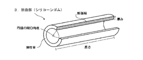
- FIG. 2 shows a schematic explanatory diagram of a silicone rubber tube used for the bent portion 3.
- This silicone rubber tube is obtained by cutting out a part of the tube and has a substantially arcuate cross section.
- the opening angle of the cross-sectional arc shape formed by the cut-out region of the tube is not particularly limited, but is preferably 0 to 90 ° or 180 °.
- the opening angle is 0 °, which means that the tube is only cut and a part thereof is not cut.
- the 1st member and the 2nd member can be closed more. From the viewpoint of more reliably closing, it is preferably 60 ° or less, more preferably 30 ° or less, and particularly preferably 0 °.
- 180 ° since a tube cut in half can be used, two bent portions can be produced from one tube, and the yield increases.
- the shape of the silicone rubber is not particularly limited as long as it is distorted by deformation and urges the first member and the second member in the closing direction.
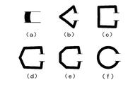
- a columnar member connecting the inner surfaces of the first member and the second member and as shown in FIGS. 3 (b) to 3 (f), the first member and the second member.
- interposes the outer surface of is mentioned.
- the bowl shape include a polygonal shape such as a triangular shape, a quadrangular shape, a pentagonal shape, and a hexagonal shape (see FIGS. 3B to 3E); an arc shape (see FIG. 3F).
- a silicone rubber tube having a substantially arc-shaped cross section is preferable from the viewpoint that no load is locally applied when strain occurs and the durability is excellent.
- the size of the silicone rubber tube is not particularly limited. For example, a tube having an outer diameter of 6 to 20 mm and a thickness of 0.5 to 5 mm is used. When the silicone rubber tube of this size is used, since the bent portion 3 has an appropriate stress, it can be easily opened with a weak force and a hinge excellent in usability can be realized.
- the lower limit of the outer diameter is preferably 7 mm or more, and more preferably 8 mm or more.
- the upper limit value of the outer diameter is preferably 15 mm or less, more preferably 13 mm or less, and particularly preferably 11 mm or less.
- the lower limit value of the thickness is preferably 1 mm or more.
- the upper limit value of the thickness is preferably 3 mm or less, and more preferably 2 mm or less.
- the length of the silicone rubber tube is not particularly limited, but is, for example, 10 to 300 mm.
- the lower limit is preferably 20 mm or more, more preferably 50 mm or more, and particularly preferably 100 mm or more.
- As an upper limit Preferably it is 200 mm or less, More preferably, it is 180 mm or less.
- the hardness of the silicone rubber is not particularly limited, but for example, one having a hardness of 10 to 90 is used.
- the lower limit is preferably 20 or more, more preferably 40 or more, and particularly preferably 50 or more.
- As an upper limit Preferably it is 80 or less, More preferably, it is 60 or less.
- the hardness of the silicone rubber is measured using a durometer type A.
- the mass of the first member 1 and / or the second member 2 is the stress that urges the first member 1 and the second member 2 in the closing direction when the first member 1 and the second member 2 are opened 180 °. Smaller than. Thereby, when the hand is released, the first member and / or the second member are automatically closed.
- the mass of the first member 1 and / or the second member 2 is smaller than the stress, the difference between the mass of the first member 1 and / or the second member 2 and the stress is preferably 10 g or more, more preferably 20 g. It is above, Especially preferably, it is 30 g or more.
- the difference between the mass and stress of the first member 1 and / or the second member 2 is 10 g or more, the effect of quickly closing is obtained.
- the mass of at least one of the first member 1 and the second member 2 is the same as that of the first member and the second member in the open state in which the first member 1 and the second member 2 are opened 180 degrees.
- the stress may be larger than the stress biased in the closing direction. For example, when the first member 1 and the second member 2 are opened by 360 °, if a member with a large mass is placed on the top, it is pressed by the mass of the member even when the hand is released, and the open state is maintained. can do.
- the difference between the mass of the member and the stress is preferably 10 g or more, more preferably 20 g or more,
- the weight is preferably 30 g or more, particularly preferably 50 g or more.
- the stress for urging the first member 1 and the second member 2 in the closing direction when the first member 1 and the second member 2 are opened by 180 ° is 1 to 100 g. It is preferable to form it as follows. As a result, it is possible to provide a hinge that can be easily opened even with a weak force and has excellent usability. From the viewpoint that the opening / closing operation becomes smooth and the usability is particularly excellent, the lower limit value of this stress is preferably 5 g or more, more preferably 10 g or more, still more preferably 20 g or more, particularly preferably. It is 25g or more. On the other hand, the upper limit is preferably 70 g or less, more preferably 50 g or less, still more preferably 45 g or less, and particularly preferably 40 g or less.
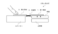
- the stress measurement method uses the apparatus shown in FIG.
- the apparatus described in FIG. 4 is an apparatus in which a balance, a weighing pan, and a spacer having the same height are arranged apart from each other.
- the first member 1 and the second member 2 of the hinge 10 are opened by 180 °, and one member (second member) is pressed onto the spacer and fixed.
- the first member is placed on a weighing pan and the weight of the balance is measured (this is referred to as “reaction force”).
- the stress for urging the first member 1 and the second member 2 in the closing direction is obtained by calculating the difference between the measured reaction force and the mass of the member placed on the weighing pan.
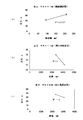
- FIG. 5A shows the relationship between the reaction force and the cross-sectional area
- FIGS. 5B and 5C show the relationship between the reaction force and the volume.
- the masses of the first member and the second member are unified.
- FIG. 5 (a) shows the results of measuring the reaction force of a silicone rubber tube having an inner diameter of 9 mm and an outer diameter of 11 mm, with the cross section changed by adjusting the length.
- FIG. 5 (b) shows a silicone rubber tube having an inner diameter of 8 mm, an outer diameter of 11 mm, and a length of 140 mm. This is a result of measuring the reaction force of the object.
- FIG. 5 (c) shows a silicone rubber tube having an inner diameter of 6 mm, an outer diameter of 8 mm, and a length of 140 mm. This is a result of measuring the reaction force of the object. From these results, it can be seen that the stress for urging the first member 1 and the second member 2 in the closing direction can be adjusted by adjusting the cross-sectional area, the volume, and the like.
- the smartphone case 100 for protecting a smartphone.
- the smartphone case 100 includes a first flat plate portion 101 (first member) that covers the liquid crystal screen of the smartphone and a second flat plate portion 102 (second member) to which the protection target holding portion 104 that holds the smartphone is fixed. It has two flat plate parts.
- the smartphone case 100 includes a bent portion 103 that linearly connects the first flat plate portion 101 and the second flat plate portion 102, and the bent portion 103 is first with the connecting line direction as the axial direction.
- the flat plate portion 101 and / or the second flat plate portion 102 can be deformed so as to rotate.
- FIG. 7 is a cross-sectional view of the bent portion 103 portion of the smartphone case 100
- FIG. 7C is a closed state in which the first flat plate portion 101 and the second flat plate portion 102 are in contact with the protection target so as to sandwich the protection target, respectively.
- closed state (0 °). B
- open state in which the first flat plate portion 101 is rotated 90 ° from the closed state (0 °).
- 90 may be abbreviated as “(90 °)”.
- A) is an open state (hereinafter referred to as “open state (180 °)”) in which the first flat plate portion 101 is rotated 180 ° from the closed state (0 °).
- the bent portion 103 includes a silicone rubber tube 105 having an arc-shaped cross section, and one end of the silicone rubber tube 105 is a plastic (polypropylene (PP)) core material 106 constituting the first flat plate portion. The other end is fixed to the PP core material 106 that constitutes the second flat plate portion by using an adhesive for hardly adhesive.
- the silicone rubber tube 105 is covered with a soft leather surface material 107 on both sides, and cannot be visually recognized from the outside.
- the silicone rubber tube 105 is obtained by cutting the silicone rubber tube in the longitudinal direction to have a circular cross section, and the closed state of the circular arc is in a non-distorted state.
- the elastic body 105 is distorted by opening the arc, and generates a stress to be closed (0 °). Even in the closed state (0 °), the strain of the silicone rubber tube 105 remains, and a force pressing the first flat plate portion 101 and the second flat plate portion 102 is applied.
- the hand mirror 200 has a first mirror part 201 (first member) and a second mirror part 202 (second member) each having a mirror surface.
- the hand mirror 200 includes a bent portion 203 that linearly connects the first mirror portion 201 and the second mirror portion 202.
- the bent portion 203 has the first mirror with the connecting linear direction as the axial direction.
- the part 201 and the second mirror part 202 can be deformed to rotate.
- a silicone rubber tube having a substantially arc-shaped cross section (opening angle: 0 °) was used as the bent portion 203.
- the mass of the 1st mirror part 201 and the 2nd mirror part 202 is designed so that it may become smaller than the stress which urges
- the folding hand mirror 200 can be manually opened and automatically closed when the hand is released. Thereby, when the hand mirror 200 is dropped, it is closed instantly and damage to the mirror surface can be suppressed.
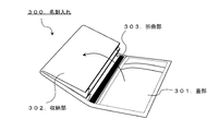
- the business card holder 300 includes a storage unit 302 (second member) that stores business cards and cards, and a lid 301 (first member) that covers the storage unit 302.
- the business card holder 300 has a bent portion 303 that linearly connects the lid portion 301 and the storage portion 302, and the bent portion 303 has the lid portion 301 and the storage portion with the connecting line direction as the axial direction. It can deform
- As the bent portion 303 a silicone rubber tube having a substantially arc-shaped cross section (opening angle: 0 °) was used.
- the silicone rubber tube has a flexible leather surface material to which the core material made of plastic (polypropylene (PP)) constituting the first member and the second member is fixed. Covered with.
- the mass of the lid portion 301 is designed to be smaller than the stress that biases the lid portion 301 and the storage portion 302 in the closing direction, and the mass of the storage portion 302 is designed to be larger than the stress. .
- the business card holder 300 operates so that the lid 301 is opened manually and the lid 301 is automatically closed when the hand is released. As a result, when the business card holder 300 is dropped, the lid 301 is instantly closed, and jumping out of the business card stored in the storage unit 302 can be suppressed.
- the coin purse 400 includes a storage unit 402 (second member) that stores coins and the like, and a lid 401 (first member) that covers the storage unit 402.
- the coin purse 400 includes a bent portion 403 that linearly connects the lid portion 401 and the storage portion 402, and the bent portion 403 has the lid portion 401 and the storage portion as an axial direction of the connecting line direction. It can deform
- the silicone rubber tube has a flexible leather surface material to which the core material made of plastic (polypropylene (PP)) constituting the first member and the second member is fixed. Covered with.
- the mass of the lid part 401 and the storage part 402 is designed to be smaller than the stress that biases the lid part 401 and the storage part 402 in the closing direction.
- the coin purse 400 operates such that the lid 401 is manually opened and the lid 401 is automatically closed when the hand is released. Thereby, when the coin purse 400 is dropped, the lid 401 is instantaneously closed, and the jumping out of the coins stored in the storage unit 402 can be suppressed.
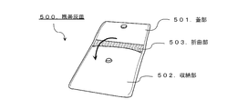
- the portable ashtray 500 includes a storage portion 502 (second member) that stores ash, cigarette butts, and the like, and a lid portion 501 (first member) that covers the storage portion 502. Further, the portable ashtray 500 includes a bent portion 503 that linearly connects the lid portion 501 and the storage portion 502, and the bent portion 503 has the lid portion 501 and the storage portion with the connecting linear direction as an axial direction. It can deform
- the silicone rubber tube has a flexible leather surface material to which the core material made of plastic (polypropylene (PP)) constituting the first member and the second member is fixed. Covered with.
- the masses of the lid portion 501 and the storage portion 502 are designed to be smaller than the stress that biases the lid portion 501 and the storage portion 502 in the closing direction.
- the portable ashtray 500 operates so that the lid 501 is manually opened and the lid 501 is automatically closed when the hand is released. Thereby, when the portable ashtray 500 is dropped, the lid portion 501 is instantaneously closed, and the ash and cigarette butts that are stored in the storage portion 502 can be prevented from jumping out.
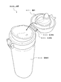
- FIG. 12 Application 6 shown in FIG. 12 is a water bottle 600.
- the water bottle 600 has a container part 602 (second member) for containing beverages and the like, and a lid part 601 (first member) that covers the container part 602. Further, the water bottle 600 has a bent portion 603 that linearly connects the lid portion 601 and the container portion 602, and the bent portion 603 has the lid portion 601 and the container portion 602 with the connecting linear direction as the axial direction. Can be deformed to rotate.
- a silicone rubber tube having a substantially arc-shaped cross section (opening angle: 0 °) was used for the bent portion 603, a silicone rubber tube having a substantially arc-shaped cross section (opening angle: 0 °) was used.
- the silicone rubber tube is fixed to a fixing plate 604 made of plastic (polypropylene (PP)), and is attached to the lid portion 601 and the container portion 602 via the fixing plate 604.
- the mass of the lid 601 is designed to be smaller than the stress that biases the lid 601 and the container 602 in the closing direction, and the mass of the container 602 is designed to be greater than the stress. .
- the water bottle 600 operates so that the lid 601 is manually opened and the lid 601 is automatically closed when the hand is released. Thereby, when the water bottle 600 is dropped, the lid portion 601 is instantaneously closed, and the drinking mouth provided on the upper portion of the container portion 602 can be covered, thereby exhibiting an excellent effect in preventing contamination.
- the hinge of the present invention protects articles that are liable to crack or break when dropped, lids for articles that want to prevent the contents from popping out when dropped, and prevents sanitary contamination when dropped It can use suitably for the lid
- it can be used as a smartphone case, a tablet-type computer case, a hand mirror, a business card holder, a card case, a coin purse, a portable ashtray, a lid for a drinking bottle of a water bottle or baby bottle, a lid for covering a pacifier, and the like.
Landscapes
- Engineering & Computer Science (AREA)
- General Engineering & Computer Science (AREA)
- Mechanical Engineering (AREA)
- Theoretical Computer Science (AREA)
- Signal Processing (AREA)
- Human Computer Interaction (AREA)
- Physics & Mathematics (AREA)
- General Physics & Mathematics (AREA)
- Telephone Set Structure (AREA)
- Casings For Electric Apparatus (AREA)
- Purses, Travelling Bags, Baskets, Or Suitcases (AREA)
- Microelectronics & Electronic Packaging (AREA)
Priority Applications (6)
| Application Number | Priority Date | Filing Date | Title |
|---|---|---|---|
| CN201780018958.5A CN108886547A (zh) | 2016-11-21 | 2017-11-21 | 铰链 |
| KR1020187028116A KR102103662B1 (ko) | 2016-11-21 | 2017-11-21 | 힌지를 갖는 스마트 폰 케이스 |
| HK18115715.2A HK1256596A1 (zh) | 2016-11-21 | 2017-11-21 | 铰链 |
| US16/090,184 US20190110566A1 (en) | 2016-11-21 | 2017-11-21 | Hinge |
| JP2018516218A JP6363319B1 (ja) | 2016-11-21 | 2017-11-21 | ヒンジ |
| EP17870676.8A EP3425887A4 (en) | 2016-11-21 | 2017-11-21 | HINGE |
Applications Claiming Priority (8)
| Application Number | Priority Date | Filing Date | Title |
|---|---|---|---|
| JP2016-237988 | 2016-11-21 | ||
| JP2016237988 | 2016-11-21 | ||
| JP2017008966 | 2017-01-04 | ||
| JP2017-008966 | 2017-01-04 | ||
| JP2017-025418 | 2017-01-30 | ||
| JP2017025418 | 2017-01-30 | ||
| JP2017-166695 | 2017-08-31 | ||
| JP2017166695 | 2017-08-31 |
Publications (1)
| Publication Number | Publication Date |
|---|---|
| WO2018092917A1 true WO2018092917A1 (ja) | 2018-05-24 |
Family
ID=62145525
Family Applications (2)
| Application Number | Title | Priority Date | Filing Date |
|---|---|---|---|
| PCT/JP2017/041883 Ceased WO2018092917A1 (ja) | 2016-11-21 | 2017-11-21 | ヒンジ |
| PCT/JP2017/041884 Ceased WO2018092918A1 (ja) | 2016-11-21 | 2017-11-21 | 保護具 |
Family Applications After (1)
| Application Number | Title | Priority Date | Filing Date |
|---|---|---|---|
| PCT/JP2017/041884 Ceased WO2018092918A1 (ja) | 2016-11-21 | 2017-11-21 | 保護具 |
Country Status (7)
| Country | Link |
|---|---|
| US (1) | US20190110566A1 (OSRAM) |
| EP (1) | EP3425887A4 (OSRAM) |
| JP (4) | JP6526914B2 (OSRAM) |
| KR (1) | KR102103662B1 (OSRAM) |
| CN (1) | CN108886547A (OSRAM) |
| HK (1) | HK1256596A1 (OSRAM) |
| WO (2) | WO2018092917A1 (OSRAM) |
Families Citing this family (6)
| Publication number | Priority date | Publication date | Assignee | Title |
|---|---|---|---|---|
| JP6849240B2 (ja) * | 2019-06-06 | 2021-03-24 | 高橋 茂 | 情報端末機収納ケース |
| KR102645562B1 (ko) * | 2020-02-24 | 2024-03-08 | (주)아모레퍼시픽 | 플립형 어플리케이터 케이스 |
| US12127651B1 (en) * | 2020-07-01 | 2024-10-29 | Apple Inc. | Items with hidden magnets |
| US12139305B2 (en) * | 2020-07-07 | 2024-11-12 | Global Dispensing North America Inc | Extruded spring strap for container and packaging applications |
| US20250066083A1 (en) * | 2021-07-06 | 2025-02-27 | Valentin Leung | Extruded Spring Strap for Container and Packaging Applications |
| WO2025225001A1 (ja) * | 2024-04-26 | 2025-10-30 | Ntt株式会社 | リビングヒンジ部材 |
Citations (4)
| Publication number | Priority date | Publication date | Assignee | Title |
|---|---|---|---|---|
| JPH05165784A (ja) * | 1991-12-13 | 1993-07-02 | Hitachi Ltd | 電子装置およびその開閉ヒンジ部構造 |
| JP3065399U (ja) * | 1998-09-30 | 2000-02-02 | グラハム・ロジャース | 眼鏡などの物品用ケースの改良 |
| JP2014141273A (ja) * | 2013-01-23 | 2014-08-07 | Jdp Kk | プラスチックヒンジ及びプラスチック開閉具 |
| JP2015115999A (ja) * | 2013-12-10 | 2015-06-22 | 矢崎総業株式会社 | 物品 |
Family Cites Families (23)
| Publication number | Priority date | Publication date | Assignee | Title |
|---|---|---|---|---|
| US6629327B2 (en) * | 2001-05-07 | 2003-10-07 | Thomas F. Adams | Combined cutting and clipping tool for sealed bags |
| US7328480B2 (en) * | 2002-10-10 | 2008-02-12 | International Automotive Components Group North America, Inc. | Coextruded living hinge, a component incorporating the hinge, and methods of making the component |
| US7588166B2 (en) * | 2003-12-10 | 2009-09-15 | Kimberly-Clark Worldwide, Inc. | Dispenser for personal care absorbent articles |
| US20070062964A1 (en) * | 2005-09-20 | 2007-03-22 | Item Source, Llc | Reclosable container with easily openable closure |
| US20070283529A1 (en) * | 2006-06-08 | 2007-12-13 | Nokia Corporation | Plastic living hinge with metal support |
| US20080000671A1 (en) * | 2006-07-03 | 2008-01-03 | Bratt Christopher R | Cable bundle clamp with two opposing spring-loaded hinged shells |
| US7354033B1 (en) * | 2006-08-01 | 2008-04-08 | The United States Of America As Represented By The Secretary Of The Air Force | Tape-spring deployable hinge |
| JP2009225193A (ja) * | 2008-03-17 | 2009-10-01 | Fujitsu Ltd | 携帯端末装置 |
| JP2011119830A (ja) * | 2009-12-01 | 2011-06-16 | Sharp Corp | 折畳み式携帯端末 |
| US9290973B2 (en) * | 2010-09-29 | 2016-03-22 | Plastek Industries, Inc. | Living hinge |
| TWM416304U (en) * | 2011-07-11 | 2011-11-11 | Fu-Yi Hsu | Protective bag |
| JP6102737B2 (ja) * | 2011-08-11 | 2017-03-29 | 日本電気株式会社 | 電子機器の収納ケース |
| JP2014082689A (ja) | 2012-10-17 | 2014-05-08 | Nobuyoshi Masuko | 携帯電子機器の保護カバー |
| CN104640472A (zh) * | 2013-09-13 | 2015-05-20 | 拉塞尔·C·斯坦纳 | 具有整体形成的有回弹力的吊钩的手机外壳 |
| CA2844886C (en) * | 2014-03-06 | 2020-09-01 | Nova Chemicals Corporation | Radiation crosslinked polyethylene hinge |
| AU2015311731A1 (en) * | 2014-09-05 | 2017-03-23 | Big Monster Toys Llc | Spill-preventing snack container and dispenser |
| US9996108B2 (en) * | 2014-09-25 | 2018-06-12 | Dell Products, Lp | Bi-stable hinge |
| US10370527B2 (en) * | 2014-12-11 | 2019-08-06 | Dow Global Technologies Llc | Polyethylene compositions having living hinge properties |
| JP6433284B2 (ja) * | 2014-12-22 | 2018-12-05 | 政之 大塚 | スマートフォン用ケース |
| CA2926462A1 (en) * | 2015-04-08 | 2016-10-08 | Gi Sportz Direct Llc | Paintball loader with hinged sidewall |
| BR112018009655B1 (pt) * | 2015-11-19 | 2022-11-08 | Dow Global Technologies Llc | Composição de polietileno adequada para uso em um componente de dobradiça viva e componente de dobradiça viva |
| US20180291949A1 (en) * | 2017-04-11 | 2018-10-11 | Dinh Le | Detent Living Hinge |
| WO2019058279A1 (en) * | 2017-09-20 | 2019-03-28 | Nexus Technologies, Inc. | HINGE |
-
2017
- 2017-11-21 EP EP17870676.8A patent/EP3425887A4/en not_active Withdrawn
- 2017-11-21 KR KR1020187028116A patent/KR102103662B1/ko active Active
- 2017-11-21 HK HK18115715.2A patent/HK1256596A1/zh unknown
- 2017-11-21 CN CN201780018958.5A patent/CN108886547A/zh active Pending
- 2017-11-21 JP JP2018516220A patent/JP6526914B2/ja not_active Expired - Fee Related
- 2017-11-21 US US16/090,184 patent/US20190110566A1/en not_active Abandoned
- 2017-11-21 WO PCT/JP2017/041883 patent/WO2018092917A1/ja not_active Ceased
- 2017-11-21 WO PCT/JP2017/041884 patent/WO2018092918A1/ja not_active Ceased
- 2017-11-21 JP JP2018516218A patent/JP6363319B1/ja active Active
-
2018
- 2018-06-27 JP JP2018121817A patent/JP7098145B2/ja active Active
-
2019
- 2019-05-08 JP JP2019088530A patent/JP2019146262A/ja active Pending
Patent Citations (4)
| Publication number | Priority date | Publication date | Assignee | Title |
|---|---|---|---|---|
| JPH05165784A (ja) * | 1991-12-13 | 1993-07-02 | Hitachi Ltd | 電子装置およびその開閉ヒンジ部構造 |
| JP3065399U (ja) * | 1998-09-30 | 2000-02-02 | グラハム・ロジャース | 眼鏡などの物品用ケースの改良 |
| JP2014141273A (ja) * | 2013-01-23 | 2014-08-07 | Jdp Kk | プラスチックヒンジ及びプラスチック開閉具 |
| JP2015115999A (ja) * | 2013-12-10 | 2015-06-22 | 矢崎総業株式会社 | 物品 |
Non-Patent Citations (1)
| Title |
|---|
| See also references of EP3425887A4 * |
Also Published As
| Publication number | Publication date |
|---|---|
| HK1256596A1 (zh) | 2019-09-27 |
| EP3425887A4 (en) | 2019-03-27 |
| JP6363319B1 (ja) | 2018-07-25 |
| JP7098145B2 (ja) | 2022-07-11 |
| EP3425887A1 (en) | 2019-01-09 |
| JP2019146262A (ja) | 2019-08-29 |
| JPWO2018092918A1 (ja) | 2018-11-15 |
| CN108886547A (zh) | 2018-11-23 |
| US20190110566A1 (en) | 2019-04-18 |
| KR20180118185A (ko) | 2018-10-30 |
| JP6526914B2 (ja) | 2019-06-05 |
| WO2018092918A1 (ja) | 2018-05-24 |
| KR102103662B1 (ko) | 2020-04-22 |
| JP2019041373A (ja) | 2019-03-14 |
| JPWO2018092917A1 (ja) | 2018-11-15 |
Similar Documents
| Publication | Publication Date | Title |
|---|---|---|
| JP6363319B1 (ja) | ヒンジ | |
| EP3698655B1 (en) | Container | |
| AU2014276618B2 (en) | Container | |
| US9452873B2 (en) | Jar and rotatable lid assembly | |
| KR102346022B1 (ko) | 사이드 커버가 회전하는 폴드 케이스 | |
| US20130050922A1 (en) | Apparatus for mounting stylus pen in an information device | |
| US20180206352A1 (en) | Pivotal Device for a Support of an Electronic Device | |
| WO2017160748A2 (en) | Double fold compact | |
| US20040035614A1 (en) | Portable scale | |
| JP2016111681A (ja) | 携帯電子端末保持具 | |
| KR200477120Y1 (ko) | 거치대로 사용가능한 휴대폰 케이스 | |
| TWI754058B (zh) | 智慧手機殼 | |
| US11371649B2 (en) | Reusable adhesive mount device for portable electronics | |
| JP2003225115A (ja) | 化粧料容器 | |
| US20210316028A1 (en) | Apparatus that attaches to mobile electronic devices and distributes sanitizer/disinfectants | |
| TW201144205A (en) | Ear cup supply device and ear cup and ear cup set | |
| US1233058A (en) | Cigarette-case. | |
| HK40072526B (zh) | 用於诸如腕表的时计或用於珠宝件的支撑元件 | |
| JP2021024606A (ja) | 綿棒容器 | |
| AU2006100293A4 (en) | Drink container holder | |
| JP6898058B2 (ja) | コンパクト容器 | |
| Bentley Jr | It's a new year... time to ask,'what does the future hold?' | |
| CN106690720A (zh) | 一种手提袋 | |
| JP2006321555A (ja) | キャップホルダ | |
| KR20160085538A (ko) | 분할 수납이 가능한 화장품 파우치 |
Legal Events
| Date | Code | Title | Description |
|---|---|---|---|
| ENP | Entry into the national phase |
Ref document number: 2018516218 Country of ref document: JP Kind code of ref document: A |
|
| ENP | Entry into the national phase |
Ref document number: 20187028116 Country of ref document: KR Kind code of ref document: A |
|
| WWE | Wipo information: entry into national phase |
Ref document number: 2017870676 Country of ref document: EP |
|
| ENP | Entry into the national phase |
Ref document number: 2017870676 Country of ref document: EP Effective date: 20181005 |
|
| 121 | Ep: the epo has been informed by wipo that ep was designated in this application |
Ref document number: 17870676 Country of ref document: EP Kind code of ref document: A1 |
|
| NENP | Non-entry into the national phase |
Ref country code: DE |