WO2018092516A1 - 中空糸膜、濾過モジュール及び排水処理装置 - Google Patents
中空糸膜、濾過モジュール及び排水処理装置 Download PDFInfo
- Publication number
- WO2018092516A1 WO2018092516A1 PCT/JP2017/038111 JP2017038111W WO2018092516A1 WO 2018092516 A1 WO2018092516 A1 WO 2018092516A1 JP 2017038111 W JP2017038111 W JP 2017038111W WO 2018092516 A1 WO2018092516 A1 WO 2018092516A1
- Authority
- WO
- WIPO (PCT)
- Prior art keywords
- hollow fiber
- fiber membrane
- less
- resin film
- aggregate
- Prior art date
- Legal status (The legal status is an assumption and is not a legal conclusion. Google has not performed a legal analysis and makes no representation as to the accuracy of the status listed.)
- Ceased
Links
Images
Classifications
-
- B—PERFORMING OPERATIONS; TRANSPORTING
- B01—PHYSICAL OR CHEMICAL PROCESSES OR APPARATUS IN GENERAL
- B01D—SEPARATION
- B01D71/00—Semi-permeable membranes for separation processes or apparatus characterised by the material; Manufacturing processes specially adapted therefor
- B01D71/06—Organic material
- B01D71/26—Polyalkenes
-
- B—PERFORMING OPERATIONS; TRANSPORTING
- B01—PHYSICAL OR CHEMICAL PROCESSES OR APPARATUS IN GENERAL
- B01D—SEPARATION
- B01D63/00—Apparatus in general for separation processes using semi-permeable membranes
- B01D63/02—Hollow fibre modules
- B01D63/031—Two or more types of hollow fibres within one bundle or within one potting or tube-sheet
-
- B—PERFORMING OPERATIONS; TRANSPORTING
- B01—PHYSICAL OR CHEMICAL PROCESSES OR APPARATUS IN GENERAL
- B01D—SEPARATION
- B01D69/00—Semi-permeable membranes for separation processes or apparatus characterised by their form, structure or properties; Manufacturing processes specially adapted therefor
- B01D69/02—Semi-permeable membranes for separation processes or apparatus characterised by their form, structure or properties; Manufacturing processes specially adapted therefor characterised by their properties
-
- B—PERFORMING OPERATIONS; TRANSPORTING
- B01—PHYSICAL OR CHEMICAL PROCESSES OR APPARATUS IN GENERAL
- B01D—SEPARATION
- B01D69/00—Semi-permeable membranes for separation processes or apparatus characterised by their form, structure or properties; Manufacturing processes specially adapted therefor
- B01D69/08—Hollow fibre membranes
-
- B—PERFORMING OPERATIONS; TRANSPORTING
- B01—PHYSICAL OR CHEMICAL PROCESSES OR APPARATUS IN GENERAL
- B01D—SEPARATION
- B01D69/00—Semi-permeable membranes for separation processes or apparatus characterised by their form, structure or properties; Manufacturing processes specially adapted therefor
- B01D69/12—Composite membranes; Ultra-thin membranes
- B01D69/1213—Laminated layers
-
- B—PERFORMING OPERATIONS; TRANSPORTING
- B01—PHYSICAL OR CHEMICAL PROCESSES OR APPARATUS IN GENERAL
- B01D—SEPARATION
- B01D71/00—Semi-permeable membranes for separation processes or apparatus characterised by the material; Manufacturing processes specially adapted therefor
- B01D71/06—Organic material
- B01D71/30—Polyalkenyl halides
- B01D71/32—Polyalkenyl halides containing fluorine atoms
- B01D71/36—Polytetrafluoroethylene
-
- C—CHEMISTRY; METALLURGY
- C02—TREATMENT OF WATER, WASTE WATER, SEWAGE, OR SLUDGE
- C02F—TREATMENT OF WATER, WASTE WATER, SEWAGE, OR SLUDGE
- C02F1/00—Treatment of water, waste water, or sewage
- C02F1/44—Treatment of water, waste water, or sewage by dialysis, osmosis or reverse osmosis
-
- C—CHEMISTRY; METALLURGY
- C02—TREATMENT OF WATER, WASTE WATER, SEWAGE, OR SLUDGE
- C02F—TREATMENT OF WATER, WASTE WATER, SEWAGE, OR SLUDGE
- C02F3/00—Biological treatment of water, waste water, or sewage
- C02F3/02—Aerobic processes
- C02F3/12—Activated sludge processes
-
- D—TEXTILES; PAPER
- D01—NATURAL OR MAN-MADE THREADS OR FIBRES; SPINNING
- D01F—CHEMICAL FEATURES IN THE MANUFACTURE OF ARTIFICIAL FILAMENTS, THREADS, FIBRES, BRISTLES OR RIBBONS; APPARATUS SPECIALLY ADAPTED FOR THE MANUFACTURE OF CARBON FILAMENTS
- D01F6/00—Monocomponent artificial filaments or the like of synthetic polymers; Manufacture thereof
-
- D—TEXTILES; PAPER
- D01—NATURAL OR MAN-MADE THREADS OR FIBRES; SPINNING
- D01F—CHEMICAL FEATURES IN THE MANUFACTURE OF ARTIFICIAL FILAMENTS, THREADS, FIBRES, BRISTLES OR RIBBONS; APPARATUS SPECIALLY ADAPTED FOR THE MANUFACTURE OF CARBON FILAMENTS
- D01F6/00—Monocomponent artificial filaments or the like of synthetic polymers; Manufacture thereof
- D01F6/02—Monocomponent artificial filaments or the like of synthetic polymers; Manufacture thereof from homopolymers obtained by reactions only involving carbon-to-carbon unsaturated bonds
- D01F6/08—Monocomponent artificial filaments or the like of synthetic polymers; Manufacture thereof from homopolymers obtained by reactions only involving carbon-to-carbon unsaturated bonds from polymers of halogenated hydrocarbons
- D01F6/12—Monocomponent artificial filaments or the like of synthetic polymers; Manufacture thereof from homopolymers obtained by reactions only involving carbon-to-carbon unsaturated bonds from polymers of halogenated hydrocarbons from polymers of fluorinated hydrocarbons
-
- D—TEXTILES; PAPER
- D06—TREATMENT OF TEXTILES OR THE LIKE; LAUNDERING; FLEXIBLE MATERIALS NOT OTHERWISE PROVIDED FOR
- D06M—TREATMENT, NOT PROVIDED FOR ELSEWHERE IN CLASS D06, OF FIBRES, THREADS, YARNS, FABRICS, FEATHERS OR FIBROUS GOODS MADE FROM SUCH MATERIALS
- D06M15/00—Treating fibres, threads, yarns, fabrics, or fibrous goods made from such materials, with macromolecular compounds; Such treatment combined with mechanical treatment
- D06M15/19—Treating fibres, threads, yarns, fabrics, or fibrous goods made from such materials, with macromolecular compounds; Such treatment combined with mechanical treatment with synthetic macromolecular compounds
- D06M15/21—Macromolecular compounds obtained by reactions only involving carbon-to-carbon unsaturated bonds
- D06M15/327—Macromolecular compounds obtained by reactions only involving carbon-to-carbon unsaturated bonds of unsaturated alcohols or esters thereof
- D06M15/333—Macromolecular compounds obtained by reactions only involving carbon-to-carbon unsaturated bonds of unsaturated alcohols or esters thereof of vinyl acetate; Polyvinylalcohol
-
- Y—GENERAL TAGGING OF NEW TECHNOLOGICAL DEVELOPMENTS; GENERAL TAGGING OF CROSS-SECTIONAL TECHNOLOGIES SPANNING OVER SEVERAL SECTIONS OF THE IPC; TECHNICAL SUBJECTS COVERED BY FORMER USPC CROSS-REFERENCE ART COLLECTIONS [XRACs] AND DIGESTS
- Y02—TECHNOLOGIES OR APPLICATIONS FOR MITIGATION OR ADAPTATION AGAINST CLIMATE CHANGE
- Y02W—CLIMATE CHANGE MITIGATION TECHNOLOGIES RELATED TO WASTEWATER TREATMENT OR WASTE MANAGEMENT
- Y02W10/00—Technologies for wastewater treatment
- Y02W10/10—Biological treatment of water, waste water, or sewage
Definitions
- the present invention relates to a hollow fiber membrane, a filtration module, and a wastewater treatment apparatus.
- This application claims priority based on Japanese Patent Application No. 2016-224141 filed on November 17, 2016, and incorporates all the description content described in the above Japanese application.
- polytetrafluoroethylene Since polytetrafluoroethylene has a relatively large hydrophobicity, its water permeability tends to be small, and especially when the pore diameter of the hollow fiber membrane is small, the filtration capacity tends to be insufficient.
- the hollow fiber membrane has a relatively large hydrophobicity, a phenomenon called fouling in which hydrophobic foulants such as oil in the water to be treated adhere to the surface of the hollow fiber membrane and become clogged easily occurs. There are also inconveniences.
- the porous membrane formed from polytetrafluoroethylene is impregnated with an aqueous solution of a hydrophilic material, and the hydrophilic material is cross-linked to be insolubilized and fixed to the pore inner surface of the porous membrane.
- Hydrophilic treatment has been proposed (see International Publication No. 2010/092938).
- the hydrophilization treatment described in the above publication includes a step of immersing the porous membrane in isopropyl alcohol compatible with an aqueous solution of a hydrophilic material, and a porous membrane containing isopropyl alcohol in the pores. It is necessary to perform a step of introducing a hydrophilic material into the pores of the porous membrane by dipping in an aqueous solution of the material, and a step of cross-linking the hydrophilic material in the pores and fixing it to the inner surface of the pores.
- Such a complicated hydrophilization treatment increases the price of the filtration membrane.
- a hollow fiber membrane according to an aspect of the present invention is mainly composed of polytetrafluoroethylene, has a porous cylindrical aggregate, and has a hydrophilic property, and covers the outer surface and the inner surface of a pore of the aggregate.
- a hollow fiber membrane having a pure water contact angle of 40 ° to 80 ° on the outer peripheral surface and a C heavy oil contact angle in water of the outer peripheral surface of 110 ° to 150 °.
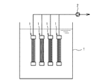
- FIG. 1 is a schematic diagram showing a configuration of a wastewater treatment apparatus according to an embodiment of the present invention.
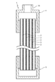
- FIG. 2 is a schematic cross-sectional view of the filtration module of the waste water treatment apparatus of FIG.
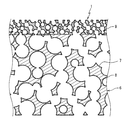
- FIG. 3 is a schematic partial cross-sectional view of the hollow fiber membrane of the filtration module of FIG.
- the present invention has been made based on the above-described circumstances, and it is an object to provide a hollow fiber membrane, a filtration module, and a wastewater treatment device that are relatively inexpensive, have a large treatment capacity, and are less likely to cause fouling.
- the hollow fiber membrane according to one embodiment of the present invention is relatively inexpensive, has a large processing capacity, and is less likely to cause fouling.
- a hollow fiber membrane according to an aspect of the present invention is mainly composed of polytetrafluoroethylene, has a porous cylindrical aggregate, and has a hydrophilic property, and covers the outer surface and the inner surface of a pore of the aggregate.
- a pure water contact angle on the outer peripheral surface is 40 ° to 80 °, and a C heavy oil contact angle in water on the outer peripheral surface is 110 ° to 150 °.
- the hollow fiber membrane is made of polytetrafluoroethylene as a main component and is made hydrophilic by covering the outer surface and the inner surface of pores with a porous cylindrical aggregate with a resin film, thereby improving water permeability.
- the processing capacity is relatively large and fouling is relatively difficult to occur.
- the hollow fiber membrane uses an appropriately hydrophilic material as a resin film forming material by setting the contact angle of pure water on the outer peripheral surface and the contact angle of C heavy oil in water within the above range. Become. Thereby, the resin film which coat
- the main component of the resin film is preferably an ethylene-vinyl alcohol copolymer, and the copolymerization ratio of ethylene in the ethylene-vinyl alcohol copolymer is preferably 20 mol% or more and 60 mol% or less.
- the main component of the resin film is an ethylene-vinyl alcohol copolymer, and the ethylene copolymer ratio in the ethylene-vinyl alcohol copolymer is within the above range.
- a resin film that can be applied and can prevent fouling can be formed relatively easily and reliably.
- the aggregate has a cylindrical support layer and a filtration layer laminated on the outer peripheral surface of the support layer.
- the average thickness of the support layer is preferably 0.3 mm to 1.0 m, the average pore diameter of the support layer is preferably 1 ⁇ m to 3 ⁇ m, and the porosity of the support layer is 40% to 90%. preferable.
- the average thickness of the filtration layer is preferably 10 ⁇ m or more and 100 ⁇ m or less, the average pore diameter of the filtration layer is preferably 0.01 ⁇ m or more and 0.45 ⁇ m or less, and the average thickness of the resin film is preferably 50 nm or less.
- the aggregate has a cylindrical support layer and a filtration layer laminated on the outer peripheral surface of the support layer, so that the hollow fiber membrane can be comparatively easily manufactured. It is possible to remove the relatively small impurities from the water to be treated. Further, by making the average thickness, average pore diameter and porosity of the support layer, the average thickness and average pore diameter of the filtration layer and the average thickness of the resin film within the above ranges, respectively, the production becomes easier. And the fall of processing capability can be prevented.
- the filtration module uses the hollow fiber membrane, it is relatively inexpensive, has a large processing capacity, and is less likely to cause fouling. Moreover, the said filtration module is equipped with a pair of holding member which fixes the both ends of a plurality of hollow fiber membranes, and uses a plurality of hollow fiber membranes simultaneously easily and reliably by being immersed in to-be-processed water. Therefore, the water to be treated can be filtered relatively easily and quickly.
- the waste water treatment apparatus includes a treated water tank for storing treated water including activated sludge, and the filtration module disposed in the treated water tank.
- the waste water treatment device is stored in a treated water tank, and the treated water containing activated sludge is filtered by the filtration module.
- the wastewater treatment apparatus is relatively inexpensive, has a large treatment capacity, and is unlikely to generate fouling, so that the wastewater can be treated relatively reliably at a relatively low cost.
- main component means a component having the largest mass content, and preferably 90% by mass or more.
- “Pure water contact angle” is a value measured by the “static drop method” defined in JIS-R3257 (1999).
- the “contact angle of C heavy oil in water” means JIS-R3257 (1999) when the measurement surface is placed horizontally downward in pure water and oil droplets of C heavy oil are allowed to stand on the lower surface of the measurement object. Is the angle between the measurement surface and the oil droplet measured in the same manner as the “contact angle” defined in the above.
- the “average pore diameter” is a value measured using a pore diameter distribution measuring device (palm porometer) manufactured by PMI, USA.
- the “porosity” is a value made in accordance with ASTM D792.
- the “bubble point” is a value measured using isopropyl alcohol according to ASTM-F316-86.
- the waste water treatment apparatus of one embodiment of the present invention shown in FIG. 1 includes a treated water tank T for storing treated water containing activated sludge, and one or a plurality of filtration modules 1 disposed in the treated water tank T. Prepare.
- the wastewater treatment apparatus further includes a filtration pump 2 that sucks out the water to be treated in the treated water tank T through the filtration module 1.
- the wastewater treatment apparatus is an aeration apparatus for supplying air (oxygen) to activated sludge, a carrier on which activated sludge adheres at a high concentration, and a bubbling for supplying bubbles for cleaning the filtration module 1.
- the treated water tank T stores the treated water so that the filtration module 1 can be immersed therein.
- a material of the treated water tank T for example, resin, metal, concrete, or the like can be used.
- the filtration module 1 is itself an embodiment of the present invention.
- the filtration module 1 includes a plurality of hollow fiber membranes 3 held in a state of being aligned in one direction (vertical direction), and both ends of the plurality of hollow fiber membranes 3.
- a pair of holding members (first holding member 4 and second holding member 5) to be fixed is provided.
- the hollow fiber membrane 3 itself is an embodiment of the present invention.
- the hollow fiber membrane 3 has a cylindrical aggregate 6 having polytetrafluoroethylene as a main component and having porosity, a hydrophilic property, and an outer surface and pores of the aggregate. And a resin film 7 covering the inner surface.
- the lower limit of the pure water contact angle on the outer peripheral surface of the hollow fiber membrane 3 is 40 °, preferably 45 °, more preferably 50 °.
- the upper limit of the pure water contact angle on the outer peripheral surface of the hollow fiber membrane 3 is 80 °, preferably 75 °, and more preferably 70 °.
- the pure water contact angle of the outer peripheral surface of the hollow fiber membrane 3 is less than the lower limit, there is a possibility that the water permeability of the hollow fiber membrane 3 may be insufficient or the occurrence of fouling may not be prevented.
- the pure water contact angle of the outer peripheral surface of the hollow fiber membrane 3 exceeds the upper limit, the formation of the resin film 7 is not easy, and the manufacturing cost of the hollow fiber membrane 3 may increase.
- the lower limit of the C heavy oil contact angle in water on the outer peripheral surface of the hollow fiber membrane 3 is 110 °, preferably 115 °, and more preferably 120 °.
- the upper limit of the C heavy oil contact angle in water on the outer peripheral surface of the hollow fiber membrane 3 is 150 °, preferably 145 °, and more preferably 140 °.
- the lower limit of the average inner diameter of the hollow fiber membrane 3 is preferably 0.3 mm, more preferably 0.5 mm, and further preferably 0.9 mm.
- the upper limit of the average inner diameter of the hollow fiber membrane 3 is preferably 4 mm, and more preferably 3 mm.
- the lower limit of the ratio of the average inner diameter to the average outer diameter of the hollow fiber membrane 3 is preferably 3/10, and more preferably 2/5.
- the upper limit of the ratio of the average inner diameter to the average outer diameter of the hollow fiber membrane 3 is preferably 4/5, and more preferably 3/5.
- the lower limit of the average effective length along the central axis of the hollow fiber membrane 3 is preferably 1 m, and more preferably 2 m.
- the upper limit of the average effective length of the hollow fiber membrane 3 is preferably 8 m, and more preferably 7 m.
- the volume efficiency of the filtration module 1 may be reduced.
- the average effective length of the hollow fiber membrane 3 exceeds the upper limit, the hollow fiber membrane 3 may be excessively bent due to its own weight, or when the filtration module 1 is installed. There is a risk that the handleability will deteriorate.
- the aggregate 6 ensures the shape and mechanical properties of the hollow fiber membrane 3 and the properties of the surface (outer surface and pore inner surface) are modified by the resin film 7.
- This aggregate 6 is mainly composed of polytetrafluoroethylene which is relatively excellent in strength, chemical resistance and ease of pore formation.
- the aggregate 6 can be configured to have a cylindrical support layer 8 and a filtration layer 9 laminated on the outer peripheral surface of the support layer 8.
- the aggregate 6 with a small effective hole diameter is improved, improving an intensity
- the lower limit of the average thickness of the support layer 8 is preferably 0.3 mm, and more preferably 0.5 mm.
- the upper limit of the average thickness of the support layer 8 is preferably 1.0 mm, and more preferably 0.8 mm. If the average thickness of the support layer 8 is less than the lower limit, the aggregate 6 and thus the strength of the hollow fiber membrane 3 may be insufficient. On the other hand, when the average thickness of the support layer 8 exceeds the above upper limit, the lumen diameter of the hollow fiber membrane 3 becomes small, and the pressure loss when the treated water is discharged may increase.
- the lower limit of the average pore diameter of the support layer 8 is preferably 1 ⁇ m, more preferably 1.5 ⁇ m.
- the upper limit of the average pore diameter of the support layer 8 is preferably 3 ⁇ m, more preferably 2.5 ⁇ m.
- the lower limit of the porosity of the support layer 8 is preferably 40%, more preferably 50%.
- the upper limit of the porosity of the support layer 8 is preferably 90%, more preferably 85%.
- the porosity of the support layer 8 is less than the above lower limit, the water permeability of the hollow fiber membrane 3 may be insufficient.
- the porosity of the support layer 8 exceeds the above upper limit, the strength of the support layer 8 and thus the hollow fiber membrane 3 may be insufficient.
- the drying temperature (atmosphere temperature) in this drying step can be, for example, 0 ° C. or higher and 60 ° C. or lower, typically room temperature. Moreover, as drying time in this drying process, it is 5 minutes or more and 24 hours or less, for example.
- Table 1 shows the measurement results of the pure water contact angle, the C heavy oil contact angle in water, and the water permeability of the filtration module in the outer peripheral surfaces of the prototypes 1 to 3 of the hollow fiber membrane.
Landscapes
- Chemical & Material Sciences (AREA)
- Chemical Kinetics & Catalysis (AREA)
- Engineering & Computer Science (AREA)
- Life Sciences & Earth Sciences (AREA)
- Textile Engineering (AREA)
- Hydrology & Water Resources (AREA)
- General Chemical & Material Sciences (AREA)
- Environmental & Geological Engineering (AREA)
- Water Supply & Treatment (AREA)
- Organic Chemistry (AREA)
- Biodiversity & Conservation Biology (AREA)
- Microbiology (AREA)
- Separation Using Semi-Permeable Membranes (AREA)
- Activated Sludge Processes (AREA)
Abstract
本発明の一態様に係る中空糸膜は、ポリテトラフルオロエチレンを主成分とし、多孔性を有する筒状の骨材と、親水性を有し、上記骨材の外表面及び空孔内面を被覆する樹脂皮膜とを備え、外周面の純水接触角が40°以上80°以下であり、外周面の水中でのC重油接触角が110°以上150°以下である。
Description
本発明は、中空糸膜、濾過モジュール及び排水処理装置に関する。本出願は、2016年11月17日出願の日本出願第2016-224141号に基づく優先権を主張し、上記日本出願に記載された全ての記載内容を援用するものである。
例えば排水処理等の多様な目的で、被処理水を濾過して固形物を除去する濾過膜の一種として、多孔質体を比較的径が小さい筒状に形成した中空糸膜が用いられることがある。このような中空糸膜の材質としては、機械的強度及び化学的安定性に比較的優れるポリテトラフルオロエチレンを主成分とするものが知られている。
ポリテトラフルオロエチレンは、比較的大きい疎水性を有するため、透水性が小さくなりやすく、特に中空糸膜の空孔径が小さい場合には濾過能力が不十分となりやすい。また、中空糸膜が比較的大きい疎水性を有する場合、被処理水中の油分等の疎水性ファウラントが中空糸膜の表面に付着して目詰まりを生じるファウリングと呼ばれる現象が発生しやすくなるという不都合もある。
そこで、ポリテトラフルオロエチレンから形成される多孔質膜に親水性材料の水溶液を含浸し、親水性材料を架橋することにより不溶化して多孔質膜の空孔内面に固定することで多孔質膜を親水化処理することが提案されている(国際公開第2010/092938号公報参照)。このように多孔質膜を親水化することによって、透水性が向上して濾過能力が増大すると共に、疎水性ファウラントの付着が抑制されるのでファウリングが発生し難くなる。
しかしながら、上記公報に記載される親水化処理は、親水性材料の水溶液と相溶性を有するイソプロピルアルコールに多孔質膜を浸漬する工程と、空孔内にイソプロピルアルコールを含んだ多孔質膜を疎水性材料の水溶液に浸漬して多孔質膜の空孔内に親水性材料を導入する工程と、空孔内の親水性材料を架橋して空孔内面に固定する工程とを行う必要がある。このように複雑な親水化処理は、濾過膜の価格を上昇させる。
本発明の一態様に係る中空糸膜は、ポリテトラフルオロエチレンを主成分とし、多孔性を有する筒状の骨材と、親水性を有し、上記骨材の外表面及び空孔内面を被覆する樹脂皮膜とを備え、外周面の純水接触角が40°以上80°以下であり、外周面の水中でのC重油接触角が110°以上150°以下である中空糸膜である。
[本開示が解決しようとする課題]
本発明は、上述のような事情に基づいてなされたものであり、比較的安価で、処理能力が大きく、かつファウリングが生じ難い中空糸膜、濾過モジュール及び排水処理装置を提供することを課題とする。
本発明は、上述のような事情に基づいてなされたものであり、比較的安価で、処理能力が大きく、かつファウリングが生じ難い中空糸膜、濾過モジュール及び排水処理装置を提供することを課題とする。
[発明の効果]
本発明の一態様に係る中空糸膜は、比較的安価で、処理能力が大きく、かつファウリングが生じ難い。
本発明の一態様に係る中空糸膜は、比較的安価で、処理能力が大きく、かつファウリングが生じ難い。
[本発明の実施形態の説明]
本発明の一態様に係る中空糸膜は、ポリテトラフルオロエチレンを主成分とし、多孔性を有する筒状の骨材と、親水性を有し、上記骨材の外表面及び空孔内面を被覆する樹脂皮膜とを備え、外周面の純水接触角が40°以上80°以下であり、外周面の水中でのC重油接触角が110°以上150°以下である。
本発明の一態様に係る中空糸膜は、ポリテトラフルオロエチレンを主成分とし、多孔性を有する筒状の骨材と、親水性を有し、上記骨材の外表面及び空孔内面を被覆する樹脂皮膜とを備え、外周面の純水接触角が40°以上80°以下であり、外周面の水中でのC重油接触角が110°以上150°以下である。
当該中空糸膜は、ポリテトラフルオロエチレンを主成分とし、多孔性を有する筒状の骨材の外表面及び空孔内面を樹脂皮膜により被覆したことによって親水化されているので、透水性が向上して処理能力が比較的大きく、かつファウリングが比較的生じ難い。また、当該中空糸膜は、外周面の純水接触角及び水中でのC重油接触角を上記範囲内としたことによって、樹脂皮膜の形成材料として適度な親水性を有する材料を使用することになる。これにより樹脂皮膜形成材料の水溶液を骨材に含浸して乾燥させるだけで骨材の外表面及び空孔内面を被覆する樹脂皮膜を容易に形成することができる。このため、当該中空糸膜は、比較的安価でありながら、処理能力が大きく、かつファウリングが生じ難い。
上記樹脂皮膜の主成分がエチレン-ビニルアルコール共重合体であるとよく、上記エチレン-ビニルアルコール共重合体におけるエチレンの共重合比としては20mol%以上60mol%以下が好ましい。このように、上記樹脂皮膜の主成分がエチレン-ビニルアルコール共重合体であり、上記エチレン-ビニルアルコール共重合体におけるエチレンの共重合比が上記範囲内であることによって、比較的大きい透水性を付与すると共にファウリングを防止できる樹脂皮膜を比較的容易かつ確実に形成することができる。
上記骨材が、筒状の支持層と、この支持層の外周面に積層される濾過層とを有するとよい。上記支持層の平均厚さとしては0.3mm以上1.0m以下が好ましく、上記支持層の平均孔径としては1μm以上3μm以下が好ましく、上記支持層の気孔率としては40%以上90%以下が好ましい。上記濾過層の平均厚さとしては10μm以上100μm以下が好ましく、上記濾過層の平均孔径としては0.01μm以上0.45μm以下が好ましく、上記樹脂皮膜の平均厚さとしては50nm以下が好ましい。このように、上記骨材が、筒状の支持層と、この支持層の外周面に積層される濾過層とを有することによって、当該中空糸膜を、比較的製造が容易でありながら、比較的強度が大きく、かつ被処理水から比較的小さい不純物を除去できるものとすることができる。また、上記支持層の平均厚さ、平均孔径及び気孔率、上記濾過層の平均厚さ及び平均孔径並びに上記樹脂皮膜の平均厚さをそれぞれ上記範囲内とすることによって、製造がより容易となり、かつ処理能力の低下を防止することができる。
バブルポイントとしては、60kPa以上200kPa以下が好ましい。このように、バブルポイントが上記範囲内であることによって、透水性が比較的大きく、かつ比較的小さい不純物を除去できるものとなる。
本発明の別の態様に係る濾過モジュールは、一方向に引き揃えられた状態で保持される複数本の当該中空糸膜と、この複数本の中空糸膜の両端部を固定する一対の保持部材とを備える。
当該濾過モジュールは、当該中空糸膜を用いるため、比較的安価で、処理能力が大きく、ファウリングが生じ難い。また、当該濾過モジュールは、複数本の中空糸膜の両端部を固定する一対の保持部材を備えることによって、被処理水中に浸漬することで複数本の中空糸膜を容易かつ確実に同時に使用することができるため、被処理水を比較的容易かつ迅速に濾過することができる。
本発明の別の態様に係る排水処理装置は、活性汚泥を含む被処理水を貯留する処理水槽と、この処理水槽内に配設される当該濾過モジュールとを備える。
当該排水処理装置は、処理水槽に貯留され、活性汚泥を含む被処理水を当該濾過モジュールによって濾過する。これにより当該排水処理装置は比較的安価で処理能力が大きく、ファウリングが生じ難いため、比較的低コストで、排水を比較的確実に処理することができる。
ここで、「主成分」とは質量含有率が最も大きい成分を意味し、好ましくは90質量%以上含有する成分とされる。「純水接触角」とは、JIS-R3257(1999)に規定される「静滴法」により測定される値である。また、「水中でのC重油接触角」とは、純水中に測定面を下向き水平に配置し、測定対象物の下面にC重油の油滴を静置した場合にJIS-R3257(1999)に規定される「接触角」と同様に測定される測定面と油滴との間の角度である。また、「平均孔径」とは、米国PMI社の細孔直径分布測定装置(パームポロメーター)を用いて測定される値である。また、「気孔率」とは、ASTM D792に準拠してされる値である。また、「バブルポイント」とは、イソプロピルアルコールを用い、ASTM-F316-86に準拠して測定される値である。
[本発明の実施形態の詳細]
以下、本発明の各実施形態について図面を参照しつつ詳説する。
以下、本発明の各実施形態について図面を参照しつつ詳説する。
[排水処理装置]
図1に示す本発明の一実施形態の排水処理装置は、活性汚泥を含む被処理水を貯留する処理水槽Tと、この処理水槽T内に配設される1又は複数の濾過モジュール1とを備える。また、当該排水処理装置は、濾過モジュール1を通して処理水槽T内の被処理水を吸い出す濾過ポンプ2をさらに備える。
図1に示す本発明の一実施形態の排水処理装置は、活性汚泥を含む被処理水を貯留する処理水槽Tと、この処理水槽T内に配設される1又は複数の濾過モジュール1とを備える。また、当該排水処理装置は、濾過モジュール1を通して処理水槽T内の被処理水を吸い出す濾過ポンプ2をさらに備える。
また、当該排水処理装置は、図示しないが、活性汚泥に空気(酸素)を供給するための曝気装置、活性汚泥が高濃度に付着する担体、濾過モジュール1を洗浄するための気泡を供給するバブリング装置、過剰な活性汚泥を排出する汚泥引き抜き装置、処理水槽T中に他の構成要素を支持するためのフレーム、制御装置等を有してもよい。
当該排水処理装置は、例えば生活排水、汚水、工場排水等の被処理水中の有機物を好気性の微生物である活性汚泥を用いて分解し、濾過モジュール1を用いて不純物を分離して排出する。つまり、当該排水処理装置は、膜分離活性汚泥法により排水を処理する装置である。
〔処理水槽〕
処理水槽Tは、濾過モジュール1を浸漬できるよう、被処理水を貯留する。処理水槽Tの材質としては、例えば樹脂、金属、コンクリート等を用いることができる。
処理水槽Tは、濾過モジュール1を浸漬できるよう、被処理水を貯留する。処理水槽Tの材質としては、例えば樹脂、金属、コンクリート等を用いることができる。
〔濾過モジュール〕
濾過モジュール1は、それ自体が本発明の一実施形態である。
濾過モジュール1は、それ自体が本発明の一実施形態である。
濾過モジュール1は、図2に示すように、一方向(上下方向)に引き揃えられた状態で保持される複数本の中空糸膜3と、この複数本の中空糸膜3の両端部をそれぞれ固定する一対の保持部材(第1保持部材4及び第2保持部材5)とを備える。
<中空糸膜>
中空糸膜3は、それ自体が本発明の一実施形態である。
中空糸膜3は、それ自体が本発明の一実施形態である。
当該中空糸膜3は、図3に示すように、ポリテトラフルオロエチレンを主成分とし、多孔性を有する筒状の骨材6と、親水性を有し、上記骨材の外表面及び空孔内面を被覆する樹脂皮膜7とを備える。
当該中空糸膜3の外周面の純水接触角の下限としては、40°であり、45°が好ましく、50°がさらに好ましい。一方、当該中空糸膜3の外周面の純水接触角の上限としては、80°であり、75°が好ましく、70°がさらに好ましい。当該中空糸膜3の外周面の純水接触角が上記下限に満たない場合、当該中空糸膜3の透水量が不十分となるおそれや、ファウリングの発生を防止できないおそれがある。逆に、当該中空糸膜3の外周面の純水接触角が上記上限を超える場合、樹脂皮膜7の形成が容易でなくなることで当該中空糸膜3の製造コストが増大するおそれがある。
当該中空糸膜3の外周面の水中でのC重油接触角の下限としては、110°であり、115°が好ましく、120°がさらに好ましい。一方、当該中空糸膜3の外周面の水中でのC重油接触角の上限としては、150°であり、145°が好ましく、140°がさらに好ましい。当該中空糸膜3の外周面の水中でのC重油接触角が上記下限に満たない場合、樹脂皮膜7の形成が容易でなくなることで製造コストが増大するおそれがある。逆に、当該中空糸膜3の外周面の水中でのC重油接触角が上記上限を超える場合、当該中空糸膜3の透水量が不十分となるおそれや、ファウリングの発生を防止できないおそれがある。
当該中空糸膜3のバブルポイントの下限としては、60kPaが好ましく、80kPaがより好ましい。一方、当該中空糸膜3のバブルポイントの上限としては、200kPaが好ましく、180kPaがより好ましい。バブルポイントが上記下限に満たない場合、当該中空糸膜3が不純物を十分に分離できないおそれがある。逆に、バブルポイントが上記上限を超える場合、当該中空糸膜3の透水量が不十分となるおそれがある。
当該中空糸膜3の平均外径の下限としては、1mmが好ましく、1.5mmがより好ましく、2mmがさらに好ましい。一方、当該中空糸膜3の平均外径の上限としては、6mmが好ましく、5mmがより好ましく、4mmがさらに好ましい。当該中空糸膜3の平均外径が上記下限に満たない場合、当該中空糸膜3の機械的強度が不十分となるおそれがある。逆に、当該中空糸膜3の平均外径が上記上限を超える場合、当該中空糸膜3の断面積に対する表面積の比が小さくなって当該中空糸膜3の濾過効率が低下するおそれがある。
当該中空糸膜3の平均内径の下限としては、0.3mmが好ましく、0.5mmがより好ましく、0.9mmがさらに好ましい。一方、当該中空糸膜3の平均内径の上限としては、4mmが好ましく、3mmがより好ましい。当該中空糸膜3の平均内径が上記下限に満たない場合、当該中空糸膜3内の処理済水を排出するときの圧損が大きくなるおそれがある。逆に、当該中空糸膜3の平均内径が上記上限を超える場合、当該中空糸膜3の厚さが小さくなって、当該中空糸膜3の機械的強度及び不純物の透過阻止効果が不十分となるおそれがある。
当該中空糸膜3の平均外径に対する平均内径の比の下限としては、3/10が好ましく、2/5がより好ましい。一方、当該中空糸膜3の平均外径に対する平均内径の比の上限としては、4/5が好ましく、3/5がより好ましい。当該中空糸膜3の平均外径に対する平均内径の比が上記下限に満たない場合、当該中空糸膜3の厚さが必要以上に大きくなって当該中空糸膜3の透水性が低下するおそれがある。逆に、当該中空糸膜3の平均外径に対する平均内径の比が上記上限を超える場合、当該中空糸膜3の厚さが小さくなって、当該中空糸膜3の機械的強度及び不純物の透過阻止効果が不十分となるおそれがある。
当該濾過モジュール1において、当該中空糸膜3の中心軸に沿う平均有効長さの下限としては、1mが好ましく、2mがより好ましい。一方、当該中空糸膜3の平均有効長さの上限としては、8mが好ましく、7mがより好ましい。当該中空糸膜3の平均有効長さが上記下限に満たない場合、当該濾過モジュール1の体積効率が小さくなるおそれがある。逆に、当該中空糸膜3の平均有効長さが上記上限を超える場合、当該中空糸膜3の自重によって当該中空糸膜3の撓みが大きくなり過ぎるおそれや、濾過モジュール1の設置時等における取り扱い性が低下するおそれがある。
(骨材)
骨材6は、当該中空糸膜3の形状及び機械的特性を担保し、樹脂皮膜7によって表面(外表面及び空孔内面)の特性が改質される。
骨材6は、当該中空糸膜3の形状及び機械的特性を担保し、樹脂皮膜7によって表面(外表面及び空孔内面)の特性が改質される。
この骨材6は、比較的強度、耐薬品性及び空孔形成容易性に優れるポリテトラフルオロエチレンを主成分とする。
また、骨材6は、筒状の支持層8と、この支持層8の外周面に積層される濾過層9とを有する構成とすることができる。このように骨材6の強度を担保する支持層8と不純物の透過を阻止する濾過層9とを有する多層構造とすることによって、強度を向上しつつ、実効的な空孔径が小さい骨材6を比較的容易に製造可能とすることができる。
支持層8の平均厚さの下限としては、0.3mmが好ましく、0.5mmがより好ましい。一方、支持層8の平均厚さの上限としては、1.0mmが好ましく、0.8mmがより好ましい。支持層8の平均厚さが上記下限に満たない場合、骨材6ひいては当該中空糸膜3の強度が不十分となるおそれがある。逆に、支持層8の平均厚さが上記上限を超える場合、当該中空糸膜3の内腔径が小さくなって処理済水を排出するときの圧損が大きくなるおそれがある。
支持層8の平均孔径の下限としては、1μmが好ましく、1.5μmがより好ましい。一方、支持層8の平均孔径の上限としては、3μmが好ましく、2.5μmがより好ましい。支持層8の平均孔径が上記下限に満たない場合、当該中空糸膜3の透水性が不十分となるおそれがある。逆に、支持層8の平均孔径が上記上限を超える場合、当該中空糸膜3が不純物の透過を十分に阻止できないおそれがある。
支持層8の気孔率の下限としては、40%が好ましく、50%がより好ましい。一方、支持層8の気孔率の上限としては、90%が好ましく、85%がより好ましい。支持層8の気孔率が上記下限に満たない場合、当該中空糸膜3の透水性が不十分となるおそれがある。逆に、支持層8の気孔率が上記上限を超える場合、支持層8ひいては当該中空糸膜3の強度が不十分となるおそれがある。
濾過層9の平均厚さの下限としては、10μmが好ましく、12μmがより好ましい。一方、濾過層9の平均厚さの上限としては、100μmが好ましく、80μmがより好ましい。濾過層9の平均厚さが上記下限に満たない場合、当該中空糸膜3が不純物の透過を十分に阻止できないおそれがある。逆に、濾過層9の平均厚さが上記上限を超える場合、当該中空糸膜3の透水性が不十分となるおそれがある。
濾過層9の平均孔径の下限としては、0.01μmが好ましく、0.05μmがより好ましい。一方、濾過層9の平均孔径の上限としては、0.45μmが好ましく、0.3μmがより好ましい。濾過層9の平均孔径が上記下限に満たない場合、当該中空糸膜3の透水性が不十分となるおそれがある。逆に、濾過層9の平均孔径が上記上限を超える場合、当該中空糸膜3が不純物の透過を十分に阻止できないおそれがある。
濾過層9の気孔率の下限としては、40%が好ましく、50%がより好ましい。一方、濾過層9の気孔率の上限としては、80%が好ましく、70%がより好ましい。濾過層9の気孔率が上記下限に満たない場合、当該中空糸膜3の透水性が不十分となるおそれがある。逆に、濾過層9の気孔率が上記上限を超える場合、当該中空糸膜3の孔径が不均一になるおそれがある。
(樹脂皮膜)
樹脂皮膜7は、骨材6の外表面及び空孔内面を被覆し、当該中空糸膜3に親水性を付与する。
樹脂皮膜7は、骨材6の外表面及び空孔内面を被覆し、当該中空糸膜3に親水性を付与する。
樹脂皮膜7の主成分としては、親水性の部分と疎水性の部分とを有する高分子が用いられる。樹脂皮膜7が親水性の部分と疎水性の部分とを有する高分子を主成分とすることによって、高分子の疎水性の部分が骨材6に対する密着性を有し、高分子の親水性の部分が当該中空糸膜3の透水性を向上すると共にファウリングを抑制する。なお、樹脂皮膜7は、主成分とされる親水性の部分と疎水性の部分とを有する高分子以外に、例えば添加剤、反応残渣等の不純物を含んでもよい。
樹脂皮膜7の主成分とされる親水性の部分と疎水性の部分とを有する高分子としては、例えばエチレン-ビニルアルコール共重合体、ポリビニルフォルマール、フェノール系高分子等を用いることができ、中でもエチレン-ビニルアルコール共重合体を好適に用いることができる。エチレン-ビニルアルコール共重合体は、エチレン部分が疎水性を発現し、ビニルアルコール部分(特にそのヒドロキシ基)が親水性を発現する。
樹脂皮膜7の主成分とされるエチレン-ビニルアルコール共重合体におけるエチレンの共重合比の下限としては、20mol%が好ましく、22mol%がより好ましく、24mol%がさらに好ましい。一方、樹脂皮膜7の主成分とされるエチレン-ビニルアルコール共重合体におけるエチレンの共重合比の上限としては、60mol%が好ましく、55mol%がより好ましく、50mol%がさらに好ましい。樹脂皮膜7の主成分とされるエチレン-ビニルアルコール共重合体におけるエチレンの共重合比が上記下限に満たない場合、骨材6に対する密着性が不十分となり、骨材6の表面を均一に被覆することが容易でなくなるおそれがある。逆に、樹脂皮膜7の主成分とされるエチレン-ビニルアルコール共重合体におけるエチレンの共重合比が上記上限を超える場合、親水性が小さくなることで当該中空糸膜3の透水性が不十分となるおそれがある。
樹脂皮膜7の主成分とされるエチレン-ビニルアルコール共重合体の平均分子量の下限としては、5,000が好ましく、10,000がより好ましい。一方、樹脂皮膜7の主成分とされるエチレン-ビニルアルコール共重合体の平均分子量の上限としては、100,000が好ましく、50,000がより好ましい。樹脂皮膜7の主成分とされるエチレン-ビニルアルコール共重合体の平均分子量が上記下限に満たない場合、樹脂皮膜7が剥離し易くなるおそれがある。逆に、樹脂皮膜7の主成分とされるエチレン-ビニルアルコール共重合体の平均分子量が上記上限を超える場合、樹脂皮膜7の形成が容易でなくなることで当該中空糸膜3の製造コストが上昇するおそれがある。なお、「平均分子量」とは、JIS-K7252-1(2008)「プラスチック-サイズ排除クロマトグラフィーによる高分子の平均分子量及び分子量分布の求め方-第1部:通則」に準拠して、ゲル浸透クロマトグラフィー(GPC)を用いて測定される質量平均分子量を指す。
樹脂皮膜7の平均厚さの下限としては、2nmが好ましく、5nmがより好ましい。一方、樹脂皮膜7の平均厚さの上限としては、50nmが好ましく、30nmがより好ましい。樹脂皮膜7の平均厚さが上記下限に満たない場合、骨材6を連続的に被覆することができず、当該中空糸膜3の透水性及び耐ファウリング性を十分に向上できないおそれがある。逆に、樹脂皮膜7の平均厚さが上記上限を超える場合、当該中空糸膜3の気孔率が低下することにより透水性が不十分となるおそれがある。
当該中空糸膜3における樹脂皮膜7の量の下限としては、0.1質量%が好ましく、0.2質量%がより好ましい。一方、当該中空糸膜3における樹脂皮膜7の量の上限としては、2質量%が好ましく、1質量%がより好ましい。当該中空糸膜3における樹脂皮膜7の量が上記下限に満たない場合、骨材6を連続的に被覆することができず、当該中空糸膜3の透水性及び耐ファウリング性を十分に向上できないおそれがある。逆に、当該中空糸膜3における樹脂皮膜7の量が上記上限を超える場合、当該中空糸膜3の気孔率が低下することにより透水性が不十分となるおそれがある。
(中空糸膜の製造方法)
当該中空糸膜3は、骨材6に溶媒を含浸させる工程と、溶媒を含浸した骨材6に樹脂皮膜7を形成する材料(樹脂皮膜形成材料)の水溶液を導入する工程と、樹脂皮膜形成材料の水溶液を含んだ骨材6を乾燥する工程とを備える工程により製造することができる。
当該中空糸膜3は、骨材6に溶媒を含浸させる工程と、溶媒を含浸した骨材6に樹脂皮膜7を形成する材料(樹脂皮膜形成材料)の水溶液を導入する工程と、樹脂皮膜形成材料の水溶液を含んだ骨材6を乾燥する工程とを備える工程により製造することができる。
上記含浸工程で用いる溶媒としては、ポリテトラフルオロエチレンの濡れ性が高く、水との親和性が高いものであればよく、例えばイソプロピルアルコール等を用いることができる。
上記導入工程では、例えば樹脂皮膜形成材料の水溶液に骨材6を浸漬することで、骨材6の空孔内に樹脂皮膜形成材料の水溶液を導入する。ここで、骨材6の空孔内に樹脂皮膜形成材料の水溶液との相溶性が高い溶媒が充填されていることにより、樹脂皮膜形成材料の水溶液の表面張力が緩和され、比較的容易に樹脂皮膜形成材料の水溶液を骨材6の空孔内に導入することができる。
樹脂皮膜形成材料の水溶液に骨材6を浸漬する時間の下限としては、例えば樹脂皮膜形成材料野種類、水溶液の濃度、温度等の条件によもよるが、5分が好ましく、30分がより好ましい。一方、樹脂皮膜形成材料の水溶液に骨材6を浸漬する時間の上限としては、6時間が好ましく、9時間がより好ましい。樹脂皮膜形成材料の水溶液に骨材6を浸漬する時間が上記下限に満たない場合、骨材6の空孔内に樹脂皮膜形成材料を十分に導入できないおそれがある。逆に、樹脂皮膜形成材料の水溶液に骨材6を浸漬する時間が上記上限を超える場合、樹脂の付きすぎによる骨材6の気孔率の低下のおそれがある。
上記水溶液中の樹脂皮膜形成材料含有量(固形分含有量)の下限としては、0.1質量%が好ましく、0.2質量%がより好ましい。一方、上記水溶液中の樹脂皮膜形成材料含有量の上限としては、2質量%が好ましく、1質量%がより好ましい。上記水溶液中の樹脂皮膜形成材料含有量が上記下限に満たない場合、骨材6の表面を連続して被覆する樹脂皮膜7を形成できないおそれがある。逆に、上記水溶液中の樹脂皮膜形成材料含有量が上記上限を超える場合、水溶液を骨材6の空孔内に含浸できないおそれや、骨材6の空孔を閉塞させるおそれがある。
上記乾燥工程では、骨材6の空孔内の上記水溶液中の溶剤を蒸発させることにより、樹脂皮膜形成材料を骨材6の外表面及び空孔内面に膜状に付着させる。
この乾燥工程における乾燥温度(雰囲気温度)としては、例えば0℃以上60℃以下、典型的には常温とすることができる。また、この乾燥工程における乾燥時間としては、例えば5分以上24時間以下とすることができる。
<上側保持部材>
第1保持部材4は、複数の当該中空糸膜3の上端を保持する。この第1保持部材4は、保持する当該中空糸膜3の内腔と連通する内部空間を形成し、この内部空間から当該中空糸膜3によって濾過された処理済水を排出する排水ノズル10を有する。つまり、第1保持部材4の排水ノズル10に濾過ポンプ2が接続される。
第1保持部材4は、複数の当該中空糸膜3の上端を保持する。この第1保持部材4は、保持する当該中空糸膜3の内腔と連通する内部空間を形成し、この内部空間から当該中空糸膜3によって濾過された処理済水を排出する排水ノズル10を有する。つまり、第1保持部材4の排水ノズル10に濾過ポンプ2が接続される。
<下側保持部材>
第2保持部材5は、複数の当該中空糸膜3の下端を保持する。第2保持部材5は、上記第1保持部材4と同様に内部空間を形成してもよく、当該中空糸膜3の開口を閉塞するような方法で当該中空糸膜3の下端を保持してもよい。第2保持部材5は、当該中空糸膜3を折り返す部材であってもよい。つまり、当該濾過モジュール1において、隣接する当該中空糸膜3は下端が接続されていてもよい。
第2保持部材5は、複数の当該中空糸膜3の下端を保持する。第2保持部材5は、上記第1保持部材4と同様に内部空間を形成してもよく、当該中空糸膜3の開口を閉塞するような方法で当該中空糸膜3の下端を保持してもよい。第2保持部材5は、当該中空糸膜3を折り返す部材であってもよい。つまり、当該濾過モジュール1において、隣接する当該中空糸膜3は下端が接続されていてもよい。
〔利点〕
当該中空糸膜3は、外周面の純水接触角及び水中でのC重油接触角を一定の範囲内としたことによって、上述のように、一定の疎水性を有する樹脂皮膜形成材料を用いて樹脂皮膜7を形成することになるので、疎水性の骨材6の外表面及び空孔内面に樹脂皮膜形成材料を比較的容易に密着させられる。このため、当該中空糸膜3は、樹脂皮膜形成材料を骨材6の空孔内で化学反応させることなく、上記浸漬工程及び乾燥工程によって処理能力(透水性)及び耐ファウリング性を向上する樹脂皮膜7を比較的一定の品質で、比較的安価に形成することができる。また、当該濾過ユニット及び排水処理装置は、当該中空糸膜3を用いるため、比較的安価で、処理能力が大きく、かつファウリングが生じ難い。
当該中空糸膜3は、外周面の純水接触角及び水中でのC重油接触角を一定の範囲内としたことによって、上述のように、一定の疎水性を有する樹脂皮膜形成材料を用いて樹脂皮膜7を形成することになるので、疎水性の骨材6の外表面及び空孔内面に樹脂皮膜形成材料を比較的容易に密着させられる。このため、当該中空糸膜3は、樹脂皮膜形成材料を骨材6の空孔内で化学反応させることなく、上記浸漬工程及び乾燥工程によって処理能力(透水性)及び耐ファウリング性を向上する樹脂皮膜7を比較的一定の品質で、比較的安価に形成することができる。また、当該濾過ユニット及び排水処理装置は、当該中空糸膜3を用いるため、比較的安価で、処理能力が大きく、かつファウリングが生じ難い。
[その他の実施形態]
今回開示された実施の形態は全ての点で例示であって制限的なものではないと考えられるべきである。本発明の範囲は、上記実施形態の構成に限定されるものではなく、特許請求の範囲によって示され、特許請求の範囲と均等の意味及び範囲内での全ての変更が含まれることが意図される。
今回開示された実施の形態は全ての点で例示であって制限的なものではないと考えられるべきである。本発明の範囲は、上記実施形態の構成に限定されるものではなく、特許請求の範囲によって示され、特許請求の範囲と均等の意味及び範囲内での全ての変更が含まれることが意図される。
当該濾過モジュールは、内周面側の負圧により被処理水を内周面側に透過する浸漬式のものに限られず、例えば中空糸膜の外周面側を高圧にして被処理水を中空糸膜の内周面側に透過する外圧式、中空糸膜の内周面側を高圧にして被処理水を中空糸膜の外周面側に透過する内圧式等、任意の形式のものとすることができる。
当該濾過モジュールは、活性汚泥を含む水以外の被処理水を濾過するために使用されてもよい。
当該排水処理装置は、当該濾過モジュールが配設される処理水槽以外に、被処理水中の浮遊物質を沈殿させる水槽、専ら活性汚泥により有機物の分解を行う水槽等をさらに備えてもよい。
以下、実施例に基づき本発明を詳述するが、この実施例の記載に基づいて本発明が限定的に解釈されるものではない。
<中空糸膜>
ポリテトラフルオロエチレンから形成され、平均厚さ600μm、平均孔径2μm、気孔率80%の支持層と、平均厚さ15μm、平均孔径0.3μm、気孔率60%の濾過層とを有する平均外径2.3mmの筒状の骨材の外表面及び空孔内面に、エチレン-ビニルアルコール共重合体により平均厚さ20nmの樹脂皮膜を形成した中空糸膜の試作例1~3を作成した。
ポリテトラフルオロエチレンから形成され、平均厚さ600μm、平均孔径2μm、気孔率80%の支持層と、平均厚さ15μm、平均孔径0.3μm、気孔率60%の濾過層とを有する平均外径2.3mmの筒状の骨材の外表面及び空孔内面に、エチレン-ビニルアルコール共重合体により平均厚さ20nmの樹脂皮膜を形成した中空糸膜の試作例1~3を作成した。
中空糸膜の試作例1は、エチレン-ビニルアルコール共重合体におけるエチレンの共重合比を27mol%とした。中空糸膜の試作例2は、エチレン-ビニルアルコール共重合体におけるエチレンの共重合比を32mol%とした。中空糸膜の試作例3は、エチレン-ビニルアルコール共重合体におけるエチレンの共重合比を44mol%とした。
樹脂皮膜の形成は、先ず、骨材をイソプロピルアルコールに1時間浸漬し、次に、上記エチレン-ビニルアルコール共重合体の0.4質量%濃度の水溶液に6時間浸漬したものを室温で3時間乾燥させることによって行った。
これらの中空糸膜の試作例1~3について、中空糸膜を切り開いて平面状とし、外周面の純水接触角及び水中でのC重油接触角を測定した。なお、「純水接触角」は、JIS-R3257(1999)規定される「静滴法」により測定した。また、「水中でのC重油接触角」は、純水中に切り開いた中空糸膜の外周面を下向き水平に配置し、中空糸膜の外周面にC重油の油滴を静置して、JIS-R3257(1999)に規定される「接触角」と同様に中空糸膜の外周面と油滴との間の角度として測定した。
また、中空糸膜の試作例1~3を用いて、有効長40cmの中空糸膜を48本備える濾過モジュールを作成し、透水量を測定した。透水量は、純水中に濾過モジュールを浸漬し、中空糸膜の内腔を吸引して中空糸膜の内外の差圧を20kPaとして吸引される水量を測定した。
次の表1に、中空糸膜の試作例1~3の外周面の純水接触角及び水中でのC重油接触角並びに濾過モジュールの透水量の測定結果を示す。
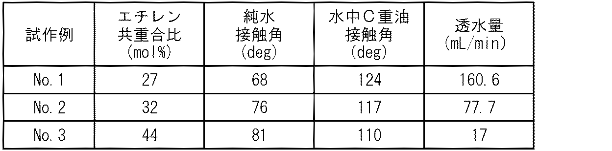
さらに、中空糸膜の試作例1~3を用いた濾過モジュールによって活性汚泥水を5日間濾過した後にその外観を確認したところ、いずれも、ファウリングは見られなかった。
以上のように、中空糸膜の外周面の純水接触角及び水中でのC重油接触角を一定の範囲内とすることによって、比較的安価に製造可能でありながら、透水量が比較的大きく、ファウリングを効果的に防止できることが確認された。
1 濾過モジュール
2 濾過ポンプ
3 中空糸膜
4 第1保持部材
5 第2保持部材
6 骨材
7 樹脂皮膜
8 支持層
9 濾過層
10 排水ノズル
T 処理水槽
2 濾過ポンプ
3 中空糸膜
4 第1保持部材
5 第2保持部材
6 骨材
7 樹脂皮膜
8 支持層
9 濾過層
10 排水ノズル
T 処理水槽
Claims (6)
- ポリテトラフルオロエチレンを主成分とし、多孔性を有する筒状の骨材と、
親水性を有し、上記骨材の外表面及び空孔内面を被覆する樹脂皮膜と
を備え、
外周面の純水接触角が40°以上80°以下であり、
外周面の水中でのC重油接触角が110°以上150°以下である中空糸膜。 - 上記樹脂皮膜の主成分がエチレン-ビニルアルコール共重合体であり、
上記エチレン-ビニルアルコール共重合体におけるエチレンの共重合比が20mol%以上60mol%以下である請求項1に記載の中空糸膜。 - 上記骨材が、筒状の支持層と、この支持層の外周面に積層される濾過層とを有し、
上記支持層の平均厚さが0.3mm以上1.0m以下であり、
上記支持層の平均孔径が1μm以上3μm以下であり、
上記支持層の気孔率が40%以上90%以下であり、
上記濾過層の平均厚さが10μm以上100μm以下であり、
上記濾過層の平均孔径が0.01μm以上0.45μm以下であり、
上記樹脂皮膜の平均厚さが50nm以下である請求項1又は請求項2に記載の中空糸膜。 - バブルポイントが60kPa以上200kPa以下である請求項1、請求項2又は請求項3に記載の中空糸膜。
- 一方向に引き揃えられた状態で保持される複数本の請求項1に記載の中空糸膜と、この複数本の中空糸膜の両端部を固定する一対の保持部材とを備える濾過モジュール。
- 活性汚泥を含む被処理水を貯留する処理水槽と、この処理水槽内に配設される請求項5に記載の濾過モジュールとを備える排水処理装置。
Priority Applications (2)
| Application Number | Priority Date | Filing Date | Title |
|---|---|---|---|
| CN201780060655.XA CN109789376A (zh) | 2016-11-17 | 2017-10-23 | 中空纤维膜、过滤组件及废水处理装置 |
| JP2018551537A JPWO2018092516A1 (ja) | 2016-11-17 | 2017-10-23 | 中空糸膜、濾過モジュール及び排水処理装置 |
Applications Claiming Priority (2)
| Application Number | Priority Date | Filing Date | Title |
|---|---|---|---|
| JP2016-224141 | 2016-11-17 | ||
| JP2016224141 | 2016-11-17 |
Publications (1)
| Publication Number | Publication Date |
|---|---|
| WO2018092516A1 true WO2018092516A1 (ja) | 2018-05-24 |
Family
ID=62145453
Family Applications (1)
| Application Number | Title | Priority Date | Filing Date |
|---|---|---|---|
| PCT/JP2017/038111 Ceased WO2018092516A1 (ja) | 2016-11-17 | 2017-10-23 | 中空糸膜、濾過モジュール及び排水処理装置 |
Country Status (4)
| Country | Link |
|---|---|
| JP (1) | JPWO2018092516A1 (ja) |
| CN (1) | CN109789376A (ja) |
| TW (1) | TW201822875A (ja) |
| WO (1) | WO2018092516A1 (ja) |
Cited By (2)
| Publication number | Priority date | Publication date | Assignee | Title |
|---|---|---|---|---|
| JP2020075218A (ja) * | 2018-11-08 | 2020-05-21 | オルガノ株式会社 | 鉄/マンガン含有水の処理装置および処理方法 |
| JPWO2020240901A1 (ja) * | 2019-05-30 | 2020-12-03 |
Citations (3)
| Publication number | Priority date | Publication date | Assignee | Title |
|---|---|---|---|---|
| WO2010092938A1 (ja) * | 2009-02-16 | 2010-08-19 | 住友電工ファインポリマー株式会社 | 多孔質複層フィルターおよびその製造方法 |
| JP2015502840A (ja) * | 2011-11-03 | 2015-01-29 | ダブリュ.エル.ゴア アンド アソシエイツ,インコーポレイティドW.L. Gore & Associates, Incorporated | 非架橋エチレンビニルアルコールコポリマーを用いて親水性化された複合ptfe膜 |
| JP2015142902A (ja) * | 2013-12-26 | 2015-08-06 | 住友電気工業株式会社 | 再生濾過モジュール、使用済みアルカリ脱脂液の再生装置及び使用済みアルカリ脱脂液の再生方法 |
Family Cites Families (8)
| Publication number | Priority date | Publication date | Assignee | Title |
|---|---|---|---|---|
| KR100523778B1 (ko) * | 2000-07-10 | 2005-10-27 | 아사히 가세이 가부시키가이샤 | 중공 섬유막 카트리지와, 그 카트리지를 사용하는 탱크형 여과 장치 및 중공 섬유막 모듈 |
| JP3851864B2 (ja) * | 2002-10-23 | 2006-11-29 | 住友電工ファインポリマー株式会社 | 多孔質複層中空糸および該多孔質複層中空糸を備えた濾過モジュール |
| JP4704708B2 (ja) * | 2004-08-13 | 2011-06-22 | 日本合成化学工業株式会社 | 樹脂組成物及びその製造方法 |
| US20070163942A1 (en) * | 2006-01-19 | 2007-07-19 | Toray Industries, Inc. | Hollow fiber membrane module |
| CN102309924B (zh) * | 2006-06-26 | 2014-01-29 | 住友电气工业株式会社 | 过滤装置 |
| JP5959889B2 (ja) * | 2011-03-14 | 2016-08-02 | 日本ゴア株式会社 | 水処理フィルター用濾材およびその製造方法 |
| US20160115057A1 (en) * | 2013-05-30 | 2016-04-28 | Sumitomo Electric Industries, Ltd. | Filtration device and filtration method using the same |
| JP2015006653A (ja) * | 2013-05-30 | 2015-01-15 | 住友電気工業株式会社 | 濾過モジュール及び濾過装置 |
-
2017
- 2017-10-23 WO PCT/JP2017/038111 patent/WO2018092516A1/ja not_active Ceased
- 2017-10-23 CN CN201780060655.XA patent/CN109789376A/zh active Pending
- 2017-10-23 JP JP2018551537A patent/JPWO2018092516A1/ja active Pending
- 2017-10-27 TW TW106137141A patent/TW201822875A/zh unknown
Patent Citations (3)
| Publication number | Priority date | Publication date | Assignee | Title |
|---|---|---|---|---|
| WO2010092938A1 (ja) * | 2009-02-16 | 2010-08-19 | 住友電工ファインポリマー株式会社 | 多孔質複層フィルターおよびその製造方法 |
| JP2015502840A (ja) * | 2011-11-03 | 2015-01-29 | ダブリュ.エル.ゴア アンド アソシエイツ,インコーポレイティドW.L. Gore & Associates, Incorporated | 非架橋エチレンビニルアルコールコポリマーを用いて親水性化された複合ptfe膜 |
| JP2015142902A (ja) * | 2013-12-26 | 2015-08-06 | 住友電気工業株式会社 | 再生濾過モジュール、使用済みアルカリ脱脂液の再生装置及び使用済みアルカリ脱脂液の再生方法 |
Cited By (5)
| Publication number | Priority date | Publication date | Assignee | Title |
|---|---|---|---|---|
| JP2020075218A (ja) * | 2018-11-08 | 2020-05-21 | オルガノ株式会社 | 鉄/マンガン含有水の処理装置および処理方法 |
| JP7090015B2 (ja) | 2018-11-08 | 2022-06-23 | オルガノ株式会社 | 鉄/マンガン含有水の処理装置および処理方法 |
| JPWO2020240901A1 (ja) * | 2019-05-30 | 2020-12-03 | ||
| WO2020240901A1 (ja) * | 2019-05-30 | 2020-12-03 | 住友電気工業株式会社 | 中空糸膜、濾過モジュール及び排水処理装置 |
| JP7338682B2 (ja) | 2019-05-30 | 2023-09-05 | 住友電気工業株式会社 | 中空糸膜、濾過モジュール及び排水処理装置 |
Also Published As
| Publication number | Publication date |
|---|---|
| JPWO2018092516A1 (ja) | 2019-10-17 |
| CN109789376A (zh) | 2019-05-21 |
| TW201822875A (zh) | 2018-07-01 |
Similar Documents
| Publication | Publication Date | Title |
|---|---|---|
| US11433358B2 (en) | Composite reverse osmosis membrane and preparation method thereof | |
| KR102289642B1 (ko) | 복합 반투막 | |
| CA2432046C (en) | Separation membrane, separation membrane element, separation membrane module, sewage treatment apparatus, and method for making the separation membrane | |
| KR101819090B1 (ko) | 분리막, 분리막 엘리먼트 및 분리막의 제조 방법 | |
| CN105026022B (zh) | 复合半透膜及其制造方法 | |
| KR102293090B1 (ko) | 복합 반투막 | |
| CN110536743B (zh) | 复合半透膜和其制造方法 | |
| KR101971130B1 (ko) | 폴리도파민 및 그래핀 옥사이드로 이루어진 중간 지지층을 포함하는 수투과도가 향상된 초박형 정삼투막 및 이의 제조 방법 | |
| KR20130108073A (ko) | 복합 반투막 | |
| KR20150077062A (ko) | 층간접착력이 우수한 정삼투막 및 그 제조방법 | |
| KR20160026070A (ko) | 기체분리막의 제조 방법 | |
| WO2020145401A1 (ja) | 膜蒸留用モジュール及びそれを用いた膜蒸留装置 | |
| KR101743808B1 (ko) | 폴리아마이드계 복합막의 제조방법 | |
| JPWO2018092516A1 (ja) | 中空糸膜、濾過モジュール及び排水処理装置 | |
| KR20090011655A (ko) | 폴리비닐리덴디플루오라이드 중공사막의 제조방법 | |
| JP2014144441A (ja) | 複合半透膜 | |
| KR20170035814A (ko) | 수처리 분리막 및 이의 제조방법 | |
| CN113766967B (zh) | 中空纤维膜、过滤模块以及排水处理装置 | |
| KR102420963B1 (ko) | 복합 반투막 | |
| KR101434184B1 (ko) | 정삼투막 및 그의 제조방법 | |
| KR101139145B1 (ko) | 은나노입자를 포함하는 친수성 비대칭 한외여과막 및정밀여과막의 제조방법 | |
| JP2013223861A (ja) | 複合半透膜 | |
| JP2020163298A (ja) | 複合半透膜 | |
| JPH09117643A (ja) | 中空糸膜モジュール | |
| JP5961931B2 (ja) | 複合半透膜の製造方法 |
Legal Events
| Date | Code | Title | Description |
|---|---|---|---|
| 121 | Ep: the epo has been informed by wipo that ep was designated in this application |
Ref document number: 17870920 Country of ref document: EP Kind code of ref document: A1 |
|
| ENP | Entry into the national phase |
Ref document number: 2018551537 Country of ref document: JP Kind code of ref document: A |
|
| NENP | Non-entry into the national phase |
Ref country code: DE |
|
| 122 | Ep: pct application non-entry in european phase |
Ref document number: 17870920 Country of ref document: EP Kind code of ref document: A1 |